A r c h i t e c t u r e P o r t f o l i o
Exercise 01 Exercise 03 Project 01

Exercise 01 Exercise 03 Project 01
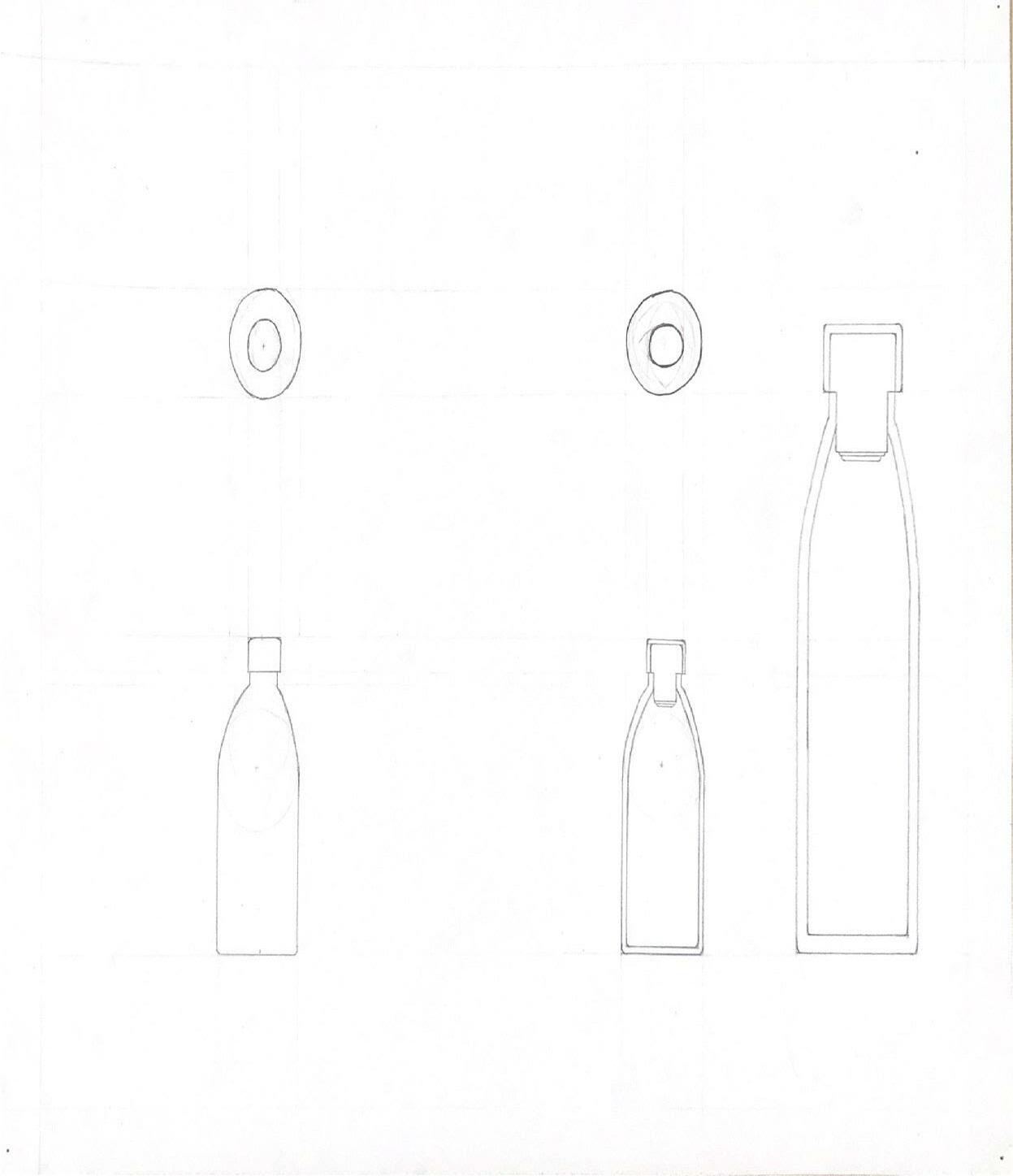
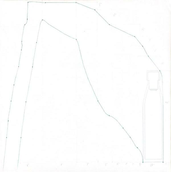
A diagram of the plan, section and elevation of a water bottle and its cap that is driven by predetermined construction lines to guide the dimensions of the objects in the drawing. Each of the drawings is drawn at half scale to the actual size of the bottle which shown by the section drawing on the right side of the paper.
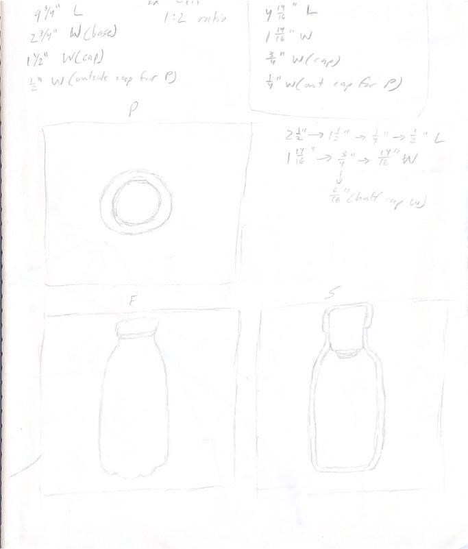
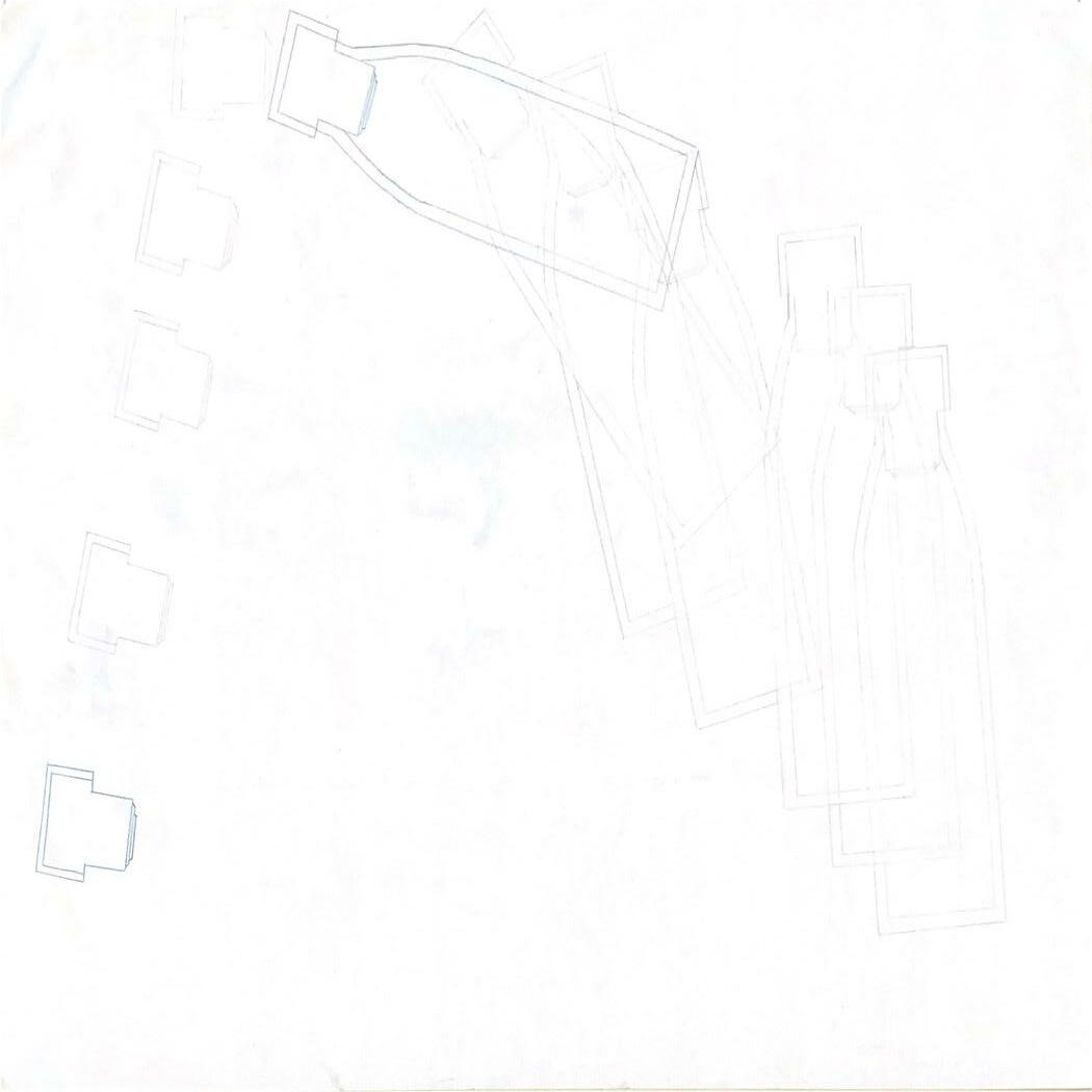
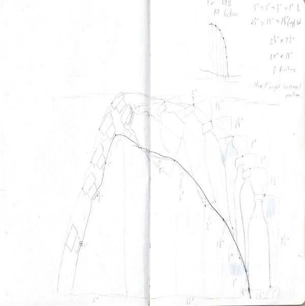
Sequential based drawing that exhibits multiple sections of the motion of lifting a water bottle to drink and taking off the cap. The differing line weights showcase a sense of hierarchy as each drawing is aggregated at a heavier line weight. The last drawings in each sequence of the bottle and the cap are heaviest as they indicate a moment of significance.
An unrolled cube plan that uses set rules to guide two continuous lines throughout. Half of the cube is cut out while the other half is kept. The plan is made so that the center of each side of the cube is open so there are voids that go through the X, Y, and Z dimensions of the cube itself. The dashed lines in the axon drawing represent these dominant voids of the cube.

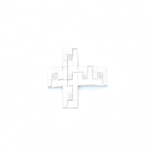
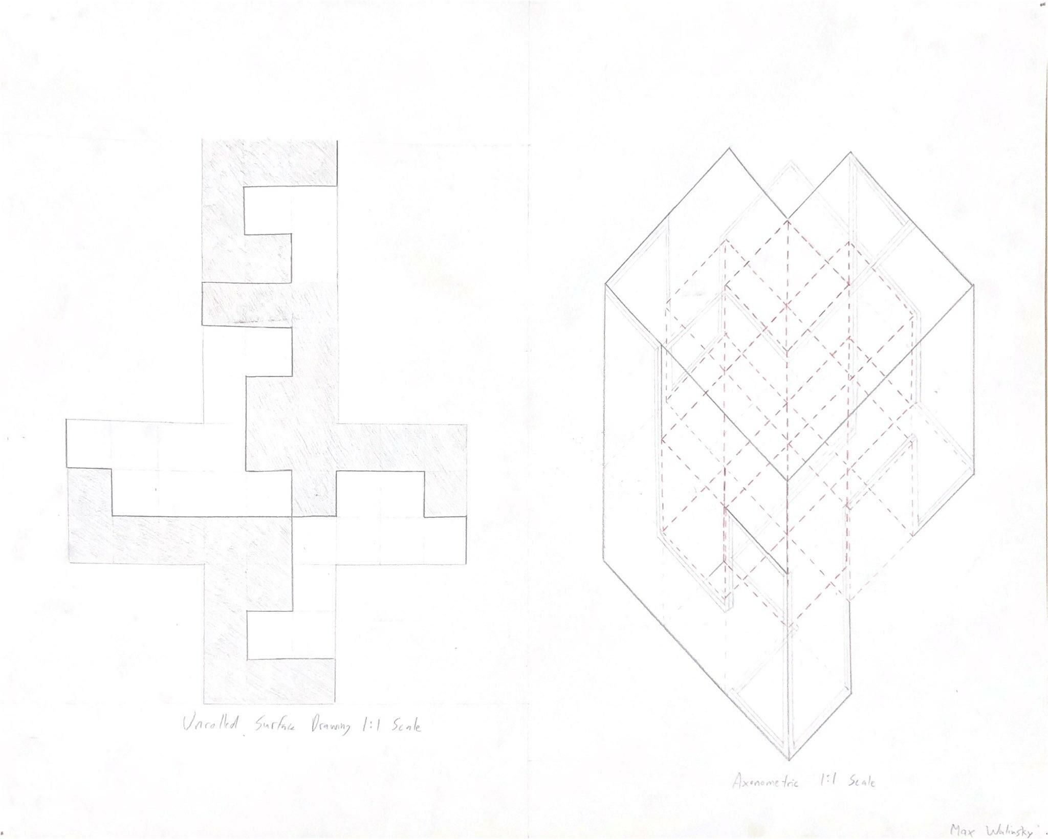 Unrolled Drawing/Axon
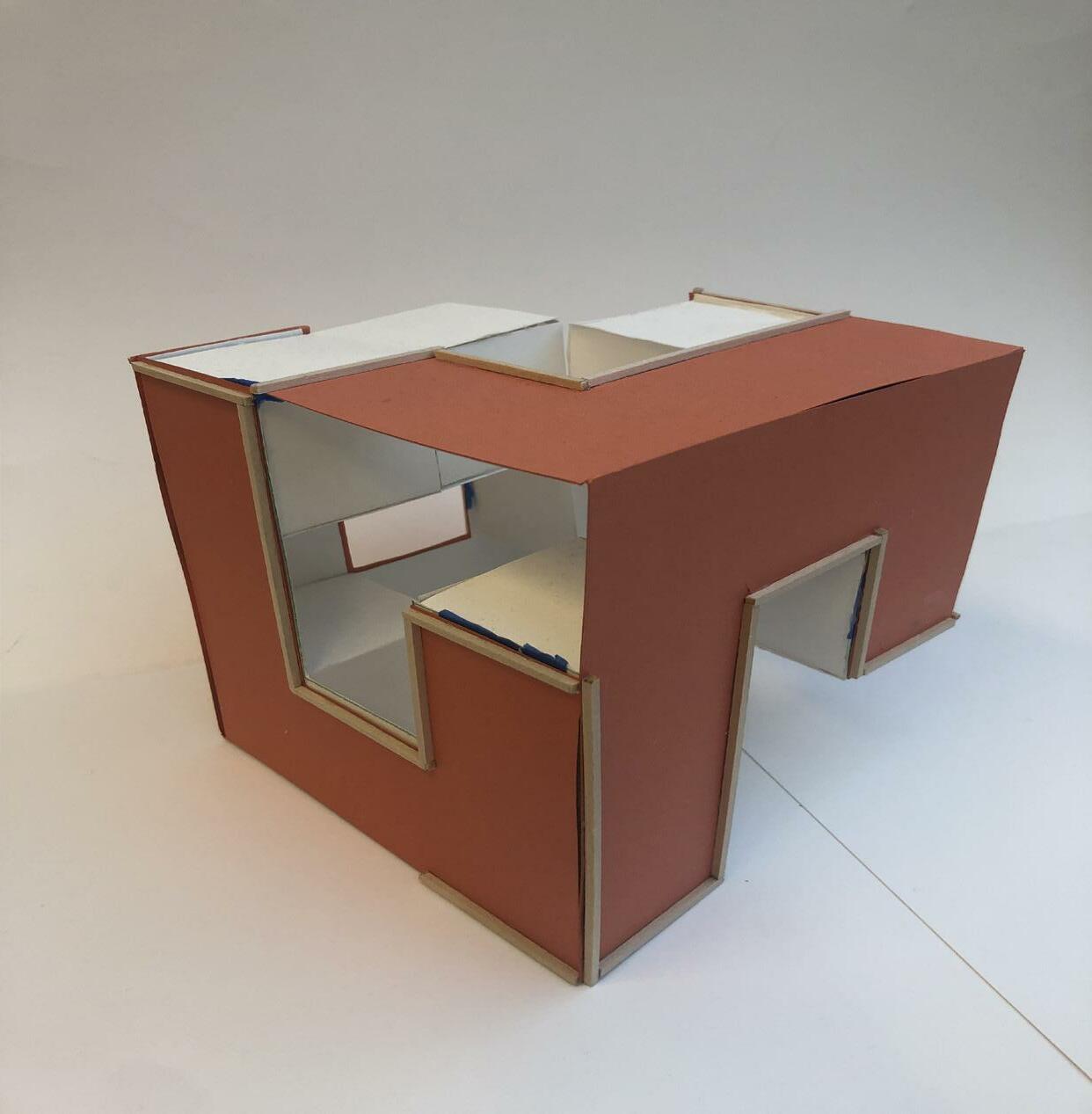
3D Model built to fruition from Previous Drawings. The outer faces of cube are made of red Bristol paper while the inner spaces are made of white bristol that portray the dominant voids of the cube. The original two continuous lines are represented by basswood sticks that wrap around and connect the frame of the cube. There is a sense of subjectivity that exists within the cube in that whichever side you pick it up from, you may experience something completely different than the intention of the design.
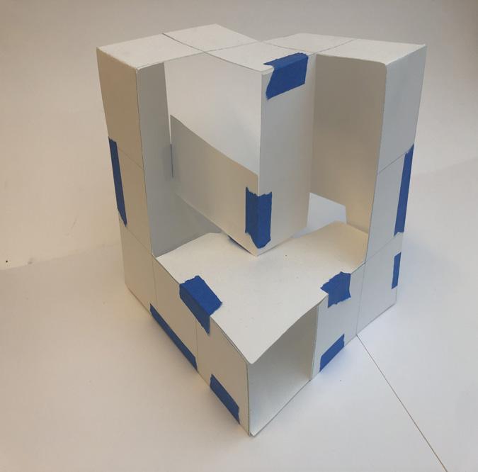
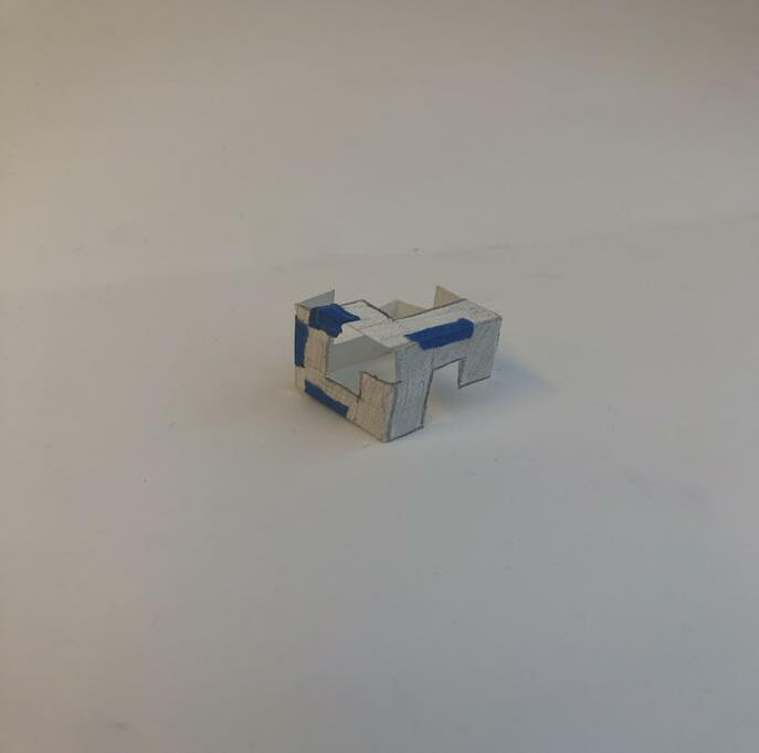

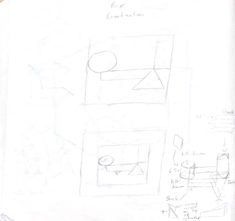
Based on an original figure ground of two dimensional geometries, the models were driven by interpreted form from given rules and compositions of space and how those visualized spaces create a real structure. This structure exhibits a sense of aggregation in which a single object is stacked and flipped on top multiple times to create a tower structure. The reinterpreted digital form showcases the element of elevation and how different the structure may seem from differing angles.
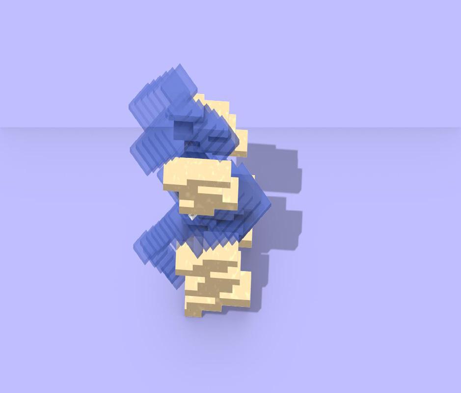
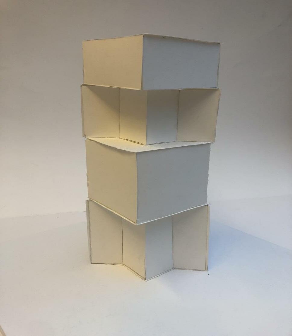

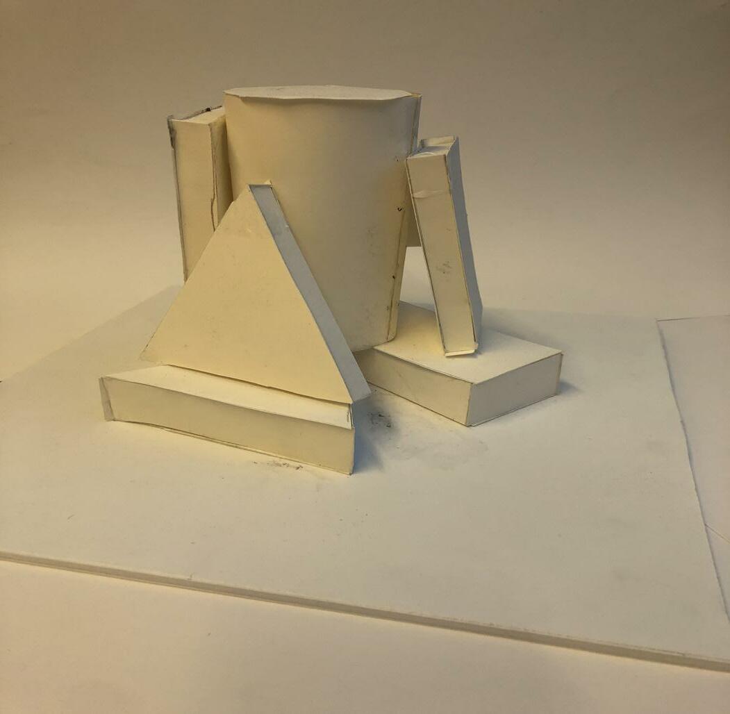
Each model type consists of set rules in which the dimensions are based on certain requirements. The latter digitized versions are reinterpreted forms of the elevations from the original model. This model is meant to be seen as a hybrid between continuous form, seen through the pyramid shape, and separating space, indicated by the circular forms cutting through.
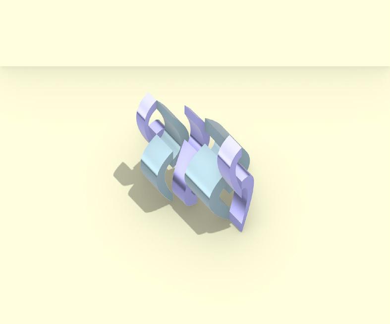
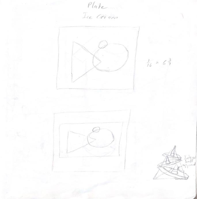
The Basis for this Model is guided by the primitive figure and the overarching concept of space and void. Even though they may seem separate from each other, each component of the model is connected in its own way to create certain implied voids. The digital model uses similar themes of the physical model, but creates a more unified form in terms of the elevation and relationship between its forms.
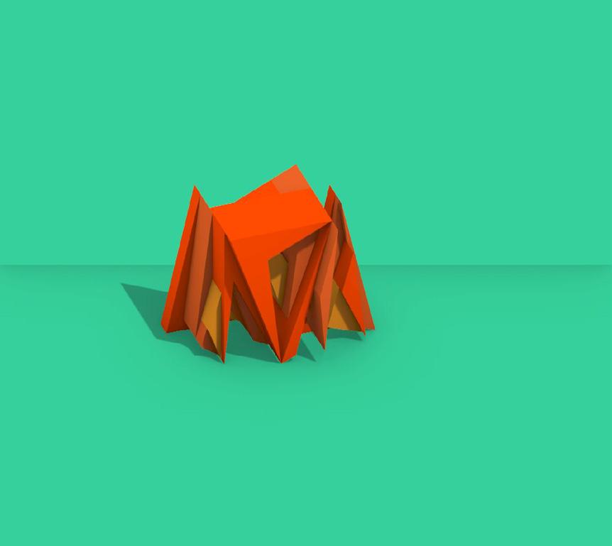
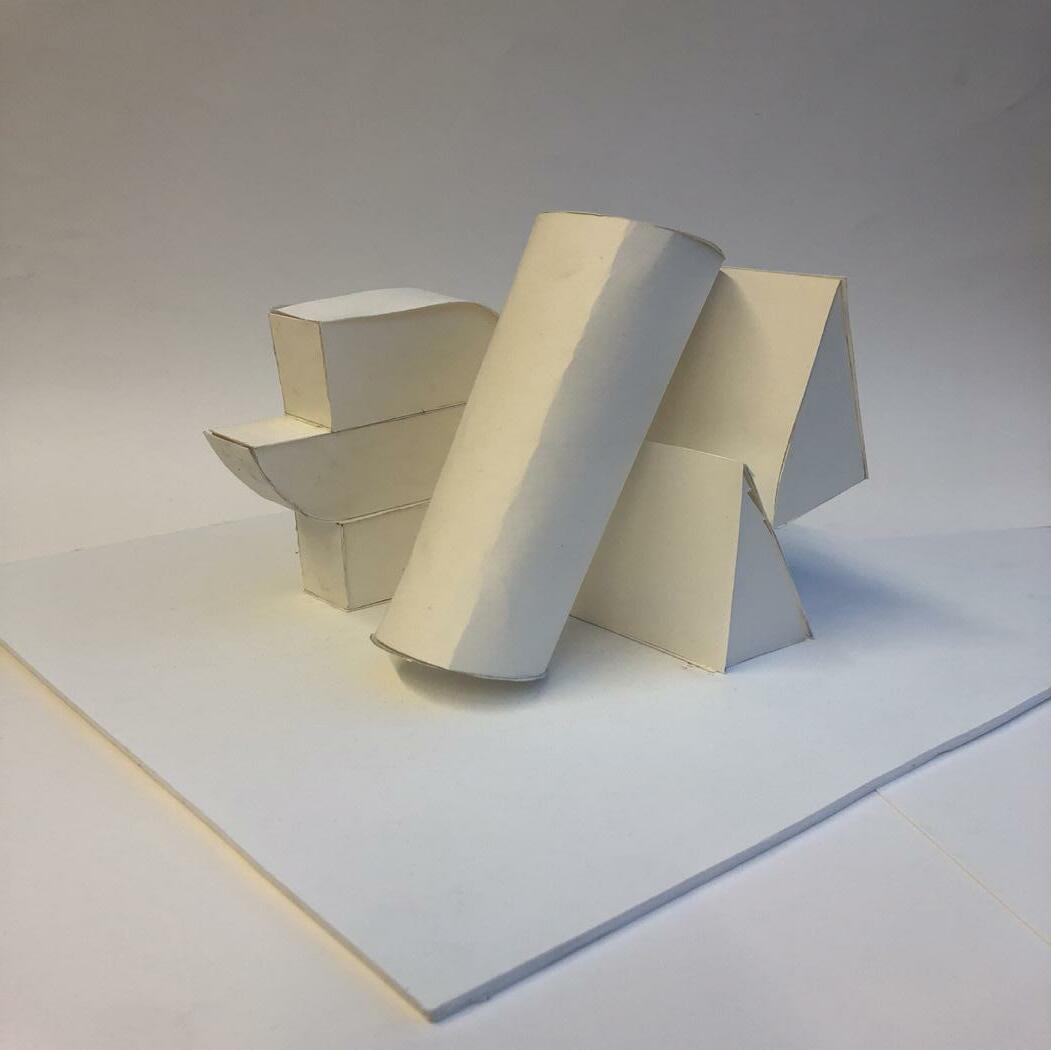

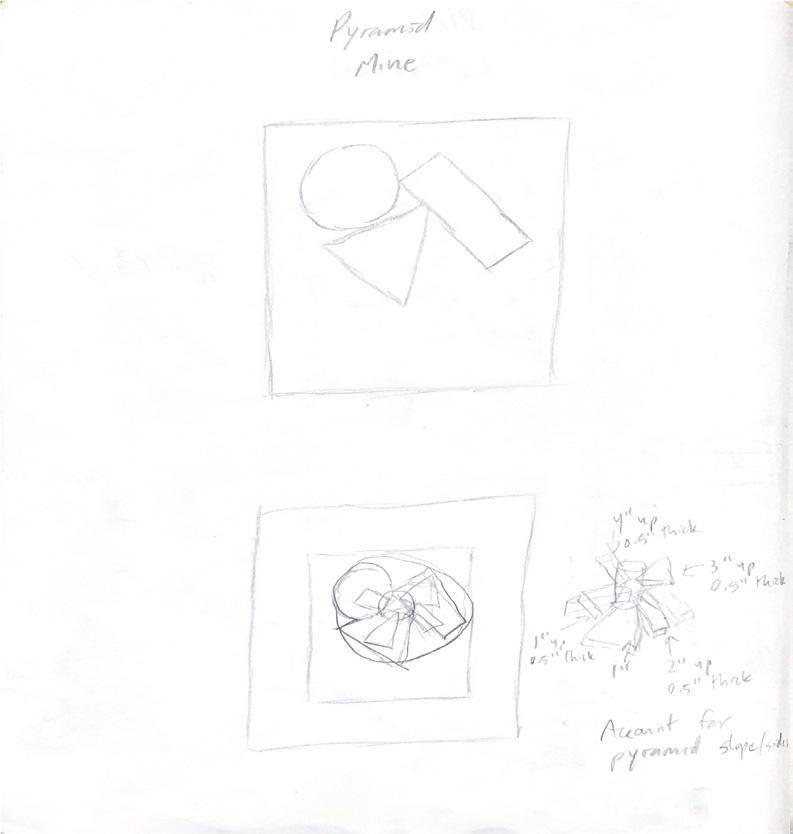
Many of the commonalities between the structures is the idea of stacking voids through form. This idea is displayed in this model more than any as the 2d geometries from the primitive figure remain consistent, but the translated 3d form becomes much more complexed. The triangles represent the idea of stacking geometries while maintaining the original primitive figure shape.
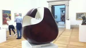
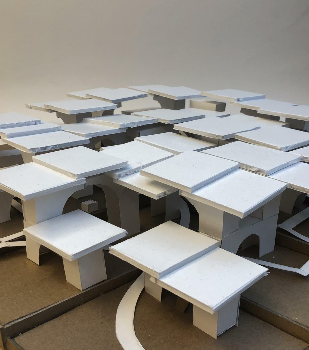
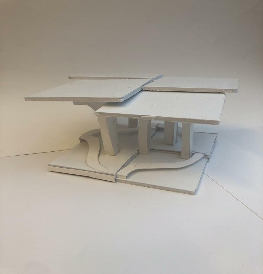
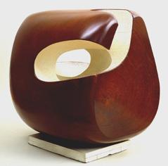
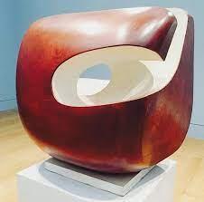
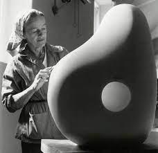
The main premise for Project 01 was based off the works of Sculptor Barbara Hepworth. The inspiration for my pavilion was driven from the sculpture called cornithos, which uses a direct carving method. I used this thinking to model the way I created the pavilion and how the different components coexist with each other in an efficient way. There were primarily 9 sculptures used throughout the pavilion in which each is corresponded by a number that is also seen on the plan for its location.

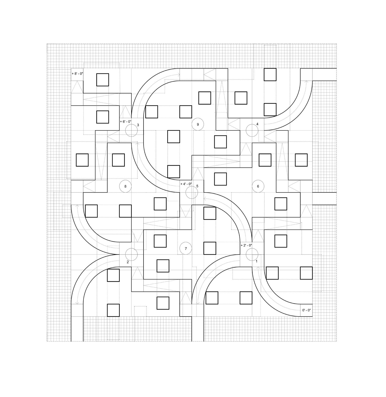
The Final Plan marks the key aspects of the pavilion. The darker line weights represent the cut through the actual site while the line weights descend in thickness based on how close they are to the cut. The entrances to the pavilion are marked on the outside and the changes in elevations are also marked. There is a sense of hierarchy that is on display in the plan in which the line weights indicate. The outer boundary of the gridded pavilion indicate the individual modules that are aggregated throughout. The outer hatching of the site indicates part of the pavilion that is simply the remaining part of the field of the site.
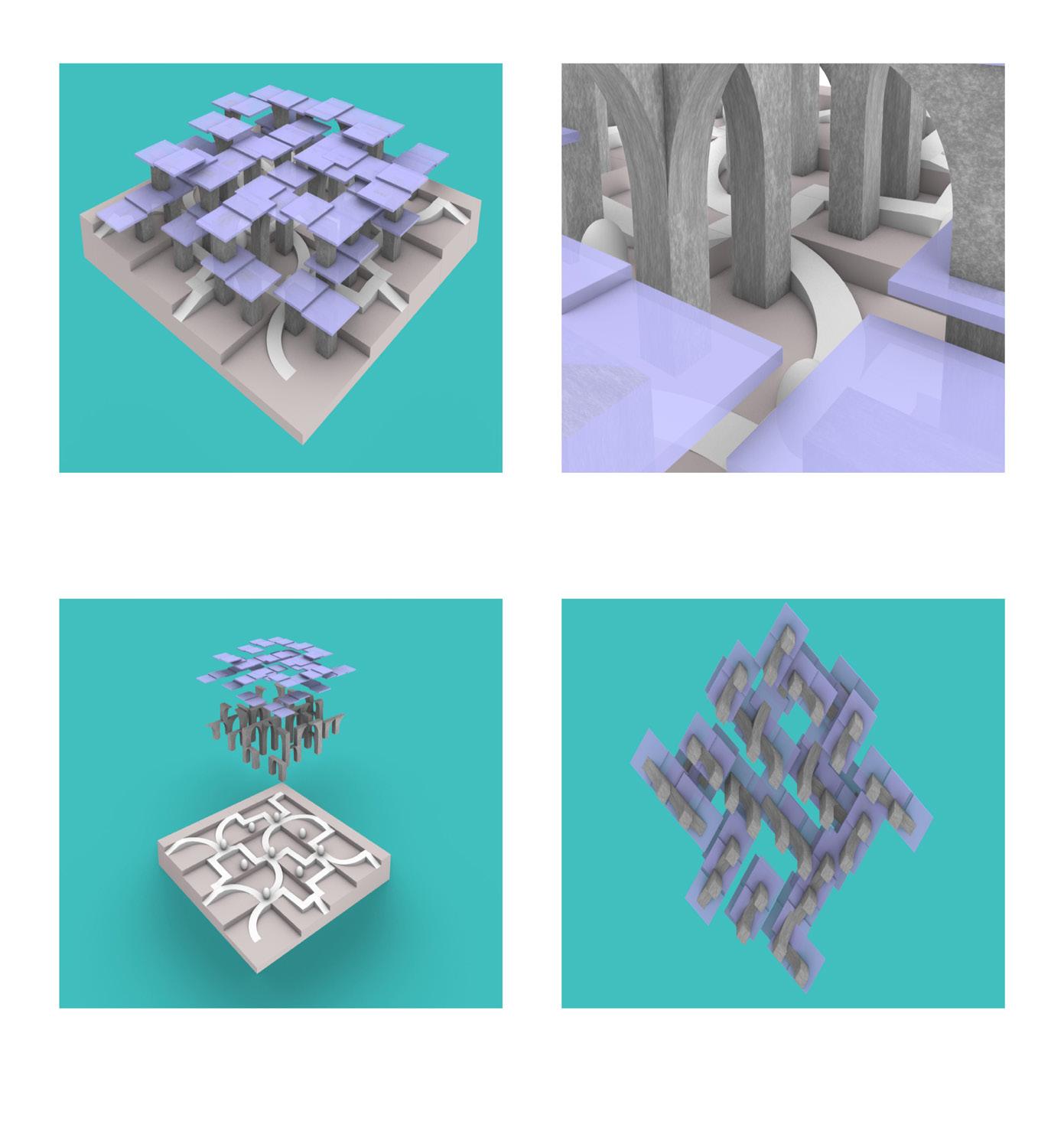
The Digital Perspectives are shown in order to enhance parts of the pavilion that may not be noticed right away. The interior perspective represents the distinction in elevations and curvature throughout the continuous circulation. The exploded axon gives a better view of the intended path of circulation meant for viewers of the pavilion, while the worms eye view showcases the eye of the viewer and what they might see when experiencing the pavilion from underneath.
Section of Prototypical space and Figure/Ground Plan
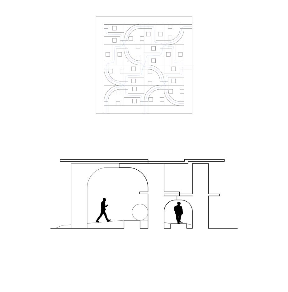

The First iteration of the model was built from the idea of modular aggregation, but built off of that with distinct walls and paths. This idea then transitioned into a more simplified space in which the modules were connected based on the main idea of continuous circulation at differing elevations. The Pillars that make up most of the structure of the pavilion are arches that you may experience right above your head as you walk underneath or in a more grand, spacious feeling. The pavilion is based off a feeling of irregularity of spaces and subjectivity of the viewer.
