6 minute read
Contrast


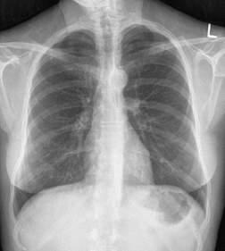
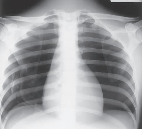
Definition Radiographic contrast is defined as the difference in density between adjacent areas of a radiographic image. When the density difference is large, the contrast is high and when the density difference is small, the contrast is low. This is demonstrated by the step wedge and by the chest radiograph in Fig. 1-126, which shows greater differences in density between adjacent areas; thus, this would be high contrast. Fig. 1-127 shows low contrast with less difference in density on adjacent areas of the step wedge and the associated radiograph.
Contrast can be described as long-scale or short-scale contrast, referring to the total range of optical densities from the lightest to the darkest part of the radiographic image. This is also demonstrated in Fig. 1-126, which shows short-scale/high-contrast (greater differences in adjacent densities and fewer visible density steps), compared with Fig. 1-127, which illustrates long-scale/ low-contrast.
Advertisement
Contrast allows the anatomic detail on a radiographic image to be visualized. Optimum radiographic contrast is important, and an understanding of contrast is essential for evaluating image quality.
Low or high contrast is not good or bad by itself. For example, low contrast (long-scale contrast) is desirable on radiographic images of the chest. Many shades of gray are required for visualization of fine lung markings, as is illustrated by the two chest radiographs in Figs. 1-126 and 1-127. The low-contrast (long-scale contrast) image in Fig. 1-127 reveals more shades of gray, as evident by the faint outlines of vertebrae that are visible through the heart and the mediastinal structures. The shades of gray that outline the vertebrae are less visible through the heart and the mediastinum on the high-contrast chest radiograph shown in Fig. 1-126.
Controlling Factors The primary controlling factor for contrast in film-based imaging is kilovoltage (kV). kV controls the energy or penetrating power of the primary x-ray beam. The higher the kV, the greater is the energy, and the more uniformly the x-ray beam penetrates the various mass densities of all tissues. Therefore, higher kV produces less variation in attenuation (differential absorption), resulting in lower contrast. kV is also a secondary controlling factor of density. Higher kV, resulting in both more numerous x-rays and greater energy x-rays, causes more x-ray energy to reach the IR, with a corresponding increase in overall density. A general rule of thumb states that a 15% increase in kV will increase film density, similar to doubling the mAs. In the lower kV range, such as 50 to 70 kV, an 8- to 10-kV increase would double the density (equivalent to doubling the mAs). In the 80- to 100-kV range, a 12- to 15-kV increase is required to double the density. The importance of this relates to radiation protection because as kV is increased, mAs can be significantly reduced, resulting in absorption of less radiation by the patient.
Other factors may affect radiographic contrast. The amount of scatter radiation the film-screen receives influences the radiographic contrast. Scatter radiation is radiation that has been changed in direction and intensity as a result of interaction with patient tissue. The amount of scatter produced depends on the intensity of the x-ray beam, the amount of tissue irradiated, and the type and thickness of the tissue. Close collimation of the x-ray field reduces the amount of tissue irradiated, reducing the amount of scatter produced and increasing contrast. Close collimation also reduces the radiation dose to the patient and the technologist.
Irradiation of thick body parts produces a considerable amount of scatter radiation, which decreases image contrast. A device called a grid is used to absorb much of the scatter radiation before it hits the IR.
Fig. 1-126 High-contrast, short-scale 50 kV, 800 mAs.
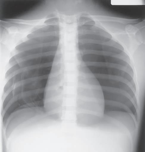
Fig. 1-127 Low-contrast, long-scale 110 kV, 10 mAs.
Grids Because the amount of scatter increases with the thickness of the tissue irradiated, it generally is recommended that a grid should be used for radiography of any body part that is thicker than 10 cm. Depending on the examination, the grid may be portable or may be built into the x-ray equipment. It is positioned between the patient and the IR and absorbs much of the scatter radiation before it hits the IR. Absorption of scatter is a key event that increases image contrast.
Correct Use of Grids An in-depth discussion of grid construction and characteristics is beyond the scope of this text. However, several rules must be followed to ensure optimal image quality when grids are used. Incorrect use of grids results in loss of optical density across all or part of the radiographic image; this feature is called grid cutoff. Grid cutoff occurs in various degrees and has several causes. Causes of grid cutoff include the following: 1. Off-center grid 2. Off-level grid
Grid CR
Center of grid Center of grid
3. Off-focus grid 4. Upside-down grid
1. Off-center grid The CR must be centered along the center axis of the grid. If it is not, lateral decentering is said to occur. The more the CR is off center from the centerline of the grid, the greater is the cutoff that results.
In certain clinical situations in which it is difficult to position the area of interest in the center of the grid, the grid may have to be turned so that the lead strips run perpendicular to the length of the patient to allow accurate centering (e.g., horizontal beam lateral lumbar spine). Exception: Decubitus—short dimension (SD)—type linear grids: An exception to the more common lengthwise focused grid with the lead strips and center axis running lengthwise with the grid is the decubitus-type crosswise linear grid. This grid, in which the lead strips and center axis are running crosswise along the shorter dimension of the grid, is useful for horizontal beam decubitus-type projections. For these projections, the grid is placed lengthwise with the patient, but the CR is centered along the crosswise axis of the grid to prevent grid cutoff.
Correctly centered grid Off-center grid (results in overall decrease in image density)
Fig. 1-128 Off-center grid cutoff.
CR
2. Off-level grid With angling, the CR must be angled along the long axis of the lead strips. Angling across the grid lines results in grid cutoff. Offlevel grid cutoff also occurs if the grid is tilted; the CR hits the lead lines at an angle (Fig. 1-129).
3. Off-focus grid A focused grid must be used at a specified siD if grid cutoff is to be prevented. Grids typically have a minimum and a maximum usable SID; this is called the focal range. The focal range is determined by the grid frequency (number of grid strips per inch or centimeter) and the grid ratio (height of lead strips compared with the space between them). Portable grids generally have a lower grid frequency and a lower grid ratio than fixed grids or Bucky-type grids. A common grid ratio for portable grids is 6:1 or 8:1 compared with 12:1 for Bucky grids. This indicates a greater focal range for portable grids, but SID limitations still exist to prevent grid cutoff (Fig. 1-130). Each technologist should know which types of portable grids are available and should know the focal range of each.
Correctly centered grid Off-level grid (transverse tilted grid, results in overall decrease in image density)
Fig. 1-129 Off-level grid cutoff.
40-inch (100-cm) SID CR 60-inch (150-cm) SID
Correct focal range
Off-focus grid, excessive SID (results in overall decrease in image density)
Fig. 1-130 Off-focus grid cutoff.