6 minute read
Digital imaging systems

Although digital technology has been used for years in digital fluoroscopy and CT (further information on these modalities is available in Chapters 12 and 18), its widespread application to general imaging is relatively new. This section introduces and briefly describes the digital imaging technology used in general radiography. Each of the systems described start the imaging process using an x-ray beam that is captured and converted into a digital signal.
Digital Imaging Systems
Advertisement
The many acronyms associated with digital imaging have created a plethora of misconceptions regarding digital imaging systems, and these misconceptions have resulted in technologists not having a thorough understanding of how various digital imaging systems work. The following sections describe the current digital imaging systems based on how the image data are captured and data extracted and secondly by their appearance. Regardless of appearance and how the image data are captured and extracted, each of the digital imaging systems described has a wide dynamic range that requires a defined exposure latitude to enable the technologist to adhere to the principles of ALARA.
PHoTosTiMUlABle sToRAge PHosPHoR (PsP) PlATe PSP technology was the first widely implemented digital imaging system for general radiography. It is most commonly called computed radiography (CR); however it is addressed in this section as storage phosphor (PSP)–based digital systems. A PSP-based digital imaging system relies on the use of a storage phosphor plate that serves the purpose of capturing and storing the x-ray beam exiting the patient. The exposure of the plate to radiation results in the migration of electrons to electron traps within the phosphor material. The greater the exposure to the plate, the greater the number of electrons moved to the electron traps. The exposed plate containing the latent image undergoes a reading process following the exposure. The reading of the plate involves scanning of the entire plate from side to side using a laser beam. As the laser moves across the plate, the trapped electrons in the phosphor are released from the electron traps and migrate back to their resting location. The migration of the electrons back to their resting locations results in the emission of light from the phosphor. The greater the exposure to the plate, the greater the intensity of the light emitted from the plate during the reading process. The light released is collected by an optical system that sends the light to a device responsible for converting the light into an analog electrical signal. The device may be a photomultiplier tube or CCD. The analog electrical signal is sent to an analog-to-digital convertor (ADC) so that the image data may be processed by the computer to create the desired digital image. Depending on the manufacturer, the image may be viewed on the technologist’s workstation 5 seconds after plate reading. After the reading process, the PSP plate is exposed to a bright light so that any remaining latent image is erased from the plate and the plate may be used for the next exposure.
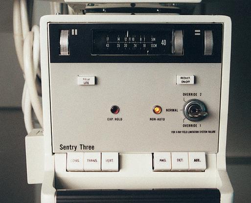
A PSP-based digital imaging system may be cassette-based or cassette-less. A cassette-based system allows the technologist to place the IR physically in a variety of locations. The cassette-less system (Figs. 1-165 and 1-166) provides the technologist with a larger device that encloses the IR. The IR in a cassette-less system has a limited amount of movement to align with the x-ray beam and anatomic structure owing to its design. The appearance of the device is not an indication of what is happening inside of the device after exposure to the x-ray beam. Therefore, it is critical that technologists recognize and understand what is inside of the equipment with which they work. TeCHnologisT WoRKsTATion The workstation includes a bar-code reader (optional), a monitor for image display, and a keyboard with a mouse or trackball for entering commands for post-processing. The technologist verifies the patient position and checks the exposure indicator at this workstation.
iMAge ARCHiVing After the image quality has been verified and any needed adjustments have been made, the image can be transmitted to the digital archive for viewing and reading by the referring physician or radiologist. Images also may be printed onto film by a laser printer.
Fig. 1-164 PSP cassette and reader.

Fig. 1-165 Cassette-less imaging system.

APPliCATion oF PsP DigiTAl sysTeMs Regardless of the technology used to acquire radiographic images, accurate positioning and attention to technical details are important. However, when digital technology is used, attention to these details becomes more important because of the following factors.
Collimation In addition to the benefit of reducing radiation dose to the patient, collimation that is closely restricted to the part that is being examined is key to ensuring optimal image quality. The software processes the entire x-ray field as a data set; any unexpected attenuation of the beam may be included in the calculations for brightness, contrast, and exposure indicator. If the collimation is not closely restricted, the exposure indicator may be misrepresented, and the image may exhibit lower contrast.
Accurate Centering of Part and IR Because of the way the extracted image data are analyzed, the body part and collimated exposure field should be centered to the IR to ensure proper image display. Failure to align the part to the receptor accurately and collimate the exposure field properly may result in poor image quality on initial image display.
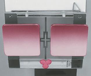
Use of Lead Masks Use of lead masks or a blocker for multiple images on a single IR is recommended when a cassette-based PSP system is used (Fig. 1-167). This recommendation is due to the hypersensitivity of the PSP plate to lower energy scatter radiation; even small amounts may affect the image. (Note: Some manufacturers recommend that only one image be centered and placed per IR. Check with your department to find out whether multiple images can be placed on a single IR.)
Use of Grids Use of grids (as explained in an earlier section of this chapter) for body parts larger (thicker) than 10 cm is especially important when images are acquired with the use of PSP image receptors because of the hypersensitivity of the image plate phosphors to scatter radiation.
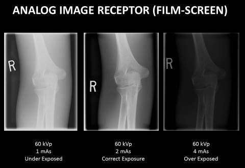
Exposure Factors Because of their wide dynamic range, PSP-based systems are able to display an acceptable image from a broad range of exposure factors (kV, mAs). It is important to remember, however, that the ALARA principle (exposure to patient as low as reasonably achievable) must be followed, and the lowest exposure factors required to obtain a diagnostic image must be used. When the image is available for viewing, the technologist must check the exposure indicator to verify that the exposure factors used are consistent with the ALARA principle and diagnostic image quality. Increasing kV by 5 to 10, while decreasing mAs by the equivalent ratio with digital imaging equipment, maintains image quality, while significantly reducing entrance skin exposure dose to the patient.
Evaluation of Exposure Indicator As soon as the image is available for viewing at the workstation, it is critiqued for positioning and exposure accuracy. The technologist must check the exposure indicator to verify that the exposure factors used were in the correct range for optimum quality with the lowest radiation dose to the patient.

Fig. 1-167 Lead blockers on cassette and close collimation are important with the use of analog (film-based) cassettes.