BLUE PAPER KEMEN 2022
EN 01 | ES 70 | FR 139 | IT 208 | DE 277 TECHNICAL MANUAL
BLUE PAPER KEMEN 2022 2 | ORBEA ORBEA | 3 TECHNICAL MANUAL EN 01 KEY TO SYMBOLS 7 02 ORBEA WARRANTY 8 Legal warranty 8 Orbea Lifetime warranty 8 Register your bicycle 8 Pedelec system components warranty 9 Warranty claims process 10 03 MAINTENANCE 11 Keep your bicycle clean 11 Keep your drivetrain lubricated 11 Inspect your bicycle before every ride 11 Components maintenance schedule 12 Pedelec system updates 14 Spare parts 14 After a crash or an impact 15 04 USE WARNINGS. KEMEN 16 Maximum tyre width 16 Minimum seatpost insertion 16 Maximum fork length 16 Maximum number of headset spacers 16 Stem position on the fork´s steerer tube 17 Intended use 17 05 USE WARNINGS. PEDELEC SYSTEM COMPONENTS 18 Maintenance and use warnings of the pedelec system components 18 Range 19 Ebike batteries transport 20 Transport of ebikes 20 06 OPERATION OF KEMEN 21 Turning Kemen On/Off 21 Checking the battery level 21 Charging the batteries 22 Switching between assist modes 26 Switching the lights On/Off 27 System errors/warnings 29 INDEX
BLUE PAPER KEMEN 2022 4 | ORBEA ORBEA | 5 TECHNICAL MANUAL EN 07 SHIMANO ETUBE PROJECT CYCLIST 30 Customization of the EP8 system 30 Checking system errors 32 08 ORBEA RS TOOLBOX. DATA FIELD FOR GARMIN DEVICES 33 Unlock and install Orbea RS Toolbox on Garmin devices. Garmin Express (PC/Mac) 33 Enabling Orbea RS Toolbox on your device 37 Using Orbea RS Toolbox 40 Activity data recording on Garmin Connect 43 09 GEOMETRY AND SIZING 44 Saddle minimum and maximum height with dropper seatposts 46 10 TECHNICAL SPECIFICATIONS 48 COMPONENTS, ASSEMBLY, USE AND SPARE PARTS 55 11 HEADSET 55 Headtube dimensions 55 Headset assembly and components 56 12 REAR AXLE AND DERAILLEUR HANGER 57 Rear trailers compatibility 57 13 PROTECTORS 58 14 CHAINRING 59 15 OTHER FRAME HARDWARE 60 16 KICKSTAND 61 17 STEM 62 Orbea Urban ICR 35 stem 62 Stem assembly and components 63 18 MECHANICAL COMPONENTS CABLE ROUTING 64 19 PEDELEC SYSTEM 65 Components connection diagram 65 Cable routing of Shimano components 68 SC-EM800 display installation on SC-E5003 equipped models Bluetooth and ANT Private connectivity 70 Orbea RS components cable routing 72 Orbea RS and Shimano pedelec system components 76 Disc brake rotors compatibilty 77 Handlebar 79 Lights 81 Front light assembly onto the stem 86 Headset integrated light assembly 86 Mudguard or rack mounted rear light assembly 87 Components cable routing and connection 88 Lights system components 91 EP8 motor assembly 92 RS 540Wh internal battery 93 Internal battery removal. Information for Orbea dealers 95 Orbea Range Extender RS 252Wh 2022 external battery 99 Important notice. Use of the Range Extender battery on Kemen 99 Range Extender assembly 101 Connection 102 Operation 103 Charge level 104 State of health 104 Error codes 105 Spare parts 106 Smart Charger RS 2A-4A 107 Relevant information about the Orbea RS batteries 110 Connection to Etube Project Professional. Information for dealers 113 20 REAR RACK AND MUDGUARDS 116 KEMEN ASPHALT 116 Rear rack and rear mudguard assembly 117 Front mudguard assembly 118 KEMEN SUV 120 Rear rack and rear mudguard assembly 123 Front mudguard assembly 125 Components and spare parts 127 21 SUSPENSIONS 133 Fox and Marzocchi forks adjustments 133 22 DECLARATION OF CONFORMITY 136 23 ADDITIONAL INFORMATION 137
This technical manual contains important information about your bicycle, its use, maintenance and replacement parts. Please read it carefully.
This document is a supplement to the General User’s Manual for Orbea bicycles and components, which describes in a more detailed manner their appropriate use and the adjustment of the general components of the bicycles for safe riding and operation. You can see and download the User’s Manual and the rest of the technical manuals for Orbea products from our website: https://www.orbea.com/gb-en/support/manuals/
You can consult the information on the use, maintenance and characteristics of the components of other manufacturers that are assembled on our bicycles, such as wheels, handlebars, pedaling assistance systems, suspension forks, etc, on the manufacturer’s website or through their dealer in your country.
Throughout this technical manual, various symbols are used that indicate instructions and warnings for use, maintenance and assembly. Pay attention to these symbols to avoid hazardous situations and ensure the correct use and assembly of all components.
The meaning of these symbols is explained below. In this manual, the symbol may appear accompanied only by the relevant instruction for the component described. Read the following information carefully in order to understand their meanings.
SAFETY INSTRUCTIONS
DANGER: Immediately hazardous situation. If not avoided, serious injury or even death will occur.
WARNING: Potentially hazardous situation. If not avoided, serious injury or even death may occur.
CAUTION: Potentially hazardous situation. If notavoided, minor or moderate injury may occur.
Not related to injury. Property situation hazard.
RISK OF ELECTRIC SHOCK: Dangerous situation. If not avoided, may cause serious injuries, or even death, due to electric shock.
RISK OF SHORT CIRCUIT: Not observing the indications may cause components to short circuit. Potential damage to components and
TOOLS AND TIGHTENING TORQUES
SPANNER ALLEN KEY
The key number is indicated inside the symbol.
TORX KEY PHILLIPS SCREWDRIVER
TIGHTENING TORQUES: The corresponding tightening torque (in Newtons/meter) is indicated beneath the symbol of the tool to use for the element described.
ASSEMBLY COMPOUNDS
OIL: Light lubrication of elements like chains and cables.
The symbols DANGER and WARNING inform about a dangerous situation that, if not avoided, may cause an accident. An accident while riding a bicycle always poses risk of serious injury or even death. In this manual, the risk of death may therefore not always be mentioned when these symbols appear, since the risk is explained here.
GREASE
GREASE: High quality assembly grease to avoid creaking and seizing.
CARBON PASTE: compound to increase friction between
LOCTITE SERIES 600: Fixing cylindrical surfaces.
LOCTITE SERIES 200: Threadlock. Medium resistance.
LOCTITE SERIES 400: Instant adhesive.
BLUE PAPER KEMEN 2022 6 | ORBEA ORBEA | 7 TECHNICAL MANUAL EN
01 KEY TO SYMBOLS 6 6 10 N.m
FIBER CARBON GRIP
Our continuous daily effort to provide maximum quality of our bicycles allows us to offer the following warranty and coverage conditions:
LEGAL WARRANTY
Orbea offers the original owner of the Orbea bicycle, rigid fork or OC/own component a legal warranty of 3 years from the date of purchase of the items, or the period stipulated as the legal warranty in the country of purchase.
This warranty covers all Orbea products against manufacturing defects and/or lack of compliance and guarantees the repair or replacement of the defective product at no cost to the affected customer. Likewise, this warranty also covers paint, varnish and corrosion defects on all frames and rigid forks assembled on our bicycles during the pe-
This warranty does not cover in any case damage derived from inappropriate use, falls or accidents or the lack of maintenance, as well as the normal wear and tear of consumable parts, such as, by way of example, but without limitation: seals, bearings, handlebar tape, spokes, tires, saddles, etc.
For a full description of the coverage conditions and the legal warranty, please visit:
www.orbea.com/gb-en/warranty/
ORBEA LIFETIME WARRANTY
As a supplement to the legal warranty, Orbea offers the original buyer of the bicycle the Orbea lifetime commercial warranty, as long as they have registered their product on the Orbea website within 30 days of its purchase. This lifetime warranty covers the frames and rigid forks that we mount on our bicycles against manufacturing defects and material conformity issues with no time limitation.
This warranty extends the original period of coverage against paint, varnish or corrosion defects on the frames and rigid forks for one additional year after the end of the legal warranty period.
Orbea’s lifetime commercial warranty only covers frames and rigid forks, but not OC components or other Orbea´s own components.
For a full description of the warranty conditions for the lifetime warranty, please visit:


www.orbea.com/gb-en/warranty/#orbea-lifetime-warranty
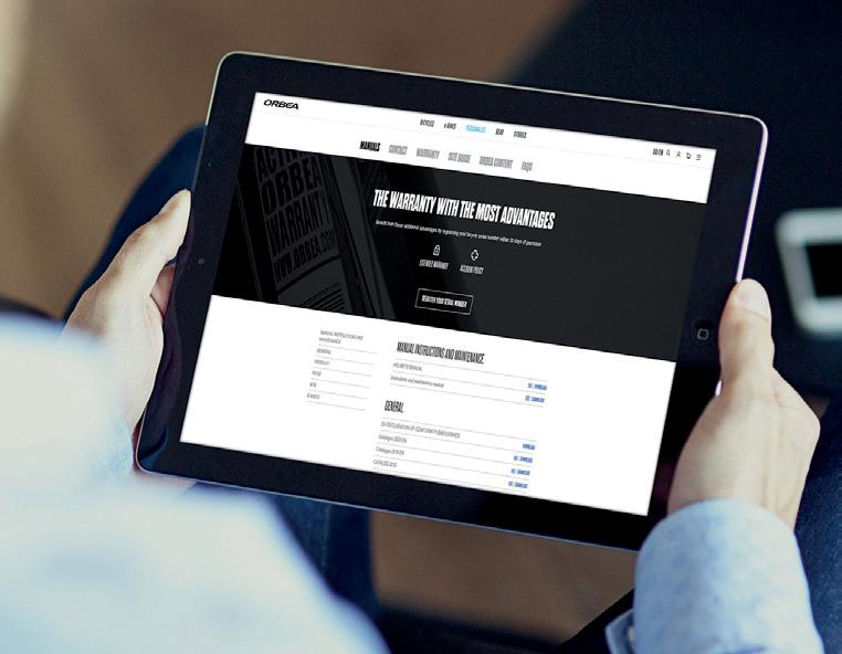
REGISTER YOUR BICYCLE
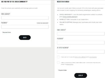
tension, you must register your bicycle within 30 days of its purchase at:
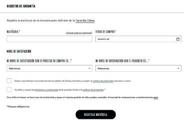
www.orbea.com/es-es/acceso-registro?from=register-plate/
-
PEDELEC SYSTEM COMPONENTS WARRANTY
SHIMANO STEPS COMPONENTS
The Shimano STEPS electric system components (motor, display, speed sensor, handlebar assist mode lever, junctions and Di2 cables) are covered by a 3 year legal warranty from the moment of purchase of the bicycle or the component by the end consumer, or the legal warranty period in the country of purchase.
Warranty claims on any of these components must be processed with Shimano through an authorised dealer.
ORBEA EXCLUSIVE COMPONENTS
The Orbea exclusive components of the pedelec system (internal battery, Range Extender, charger, harness cable, power button or Orbea lighting components) are covered by a 3 year legal warranty from the moment of purchase of the bicycle or the component by the end consumer, or the legal warranty period in the country of purchase.
Warranty claims on any of these components must be processed with Orbea through an authorised dealer.
This warranty covers all Shimano and Orbea products against manufacturing defects and/or lack of conformity and guarantees the repair or replacement of the faulty at no additional cost for the affected owner.
This warranty does not cover in any case damages derived from inadequate use, falls or accidents, incorrect installation, lack of maintenance or not observing the recommended indications of use, storage, charge, etc. described in this manual.
The loss of capacity of the RS batteries (internal battery and Range Extender) due to natural ageing of the cells due to use, charge and storage is not covered by the terms of this warranty.
BLUE PAPER KEMEN 2022 8 | ORBEA ORBEA | 9 TECHNICAL MANUAL EN
02
YOUR ACCOUNT
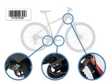
ORBEA WARRANTY 01. REGISTER
02. REGISTER YOUR BARCODE
03. WHERE TO FIND YOUR BARCODE
WARRANTY CLAIM PROCESS
All warranty claims must be processed through an authorized Orbea dealer, who will perform the initial diagnosis and send Orbea, Shimano or the affected component manufacturer all the necessary documentation for a complete diagnosis of the claim in question. The dealer will inform the owner about the status of the process and the decision made on the warranty claim by Orbea, Shimano or the component manufacturer.
WARRANTY CLAIMS AND REPAIRS OF COMPONENTS OF THE PEDELEC SYSTEM
SHIMANO: The warranty or repair claims of the following components of the pedelec system will be processed through Shimano:
· Shimano EP8 motor.
· SC-EN800, SC-E7000 or SC-E5003 displays.
· Speed sensor.
· Handlebar remote levers SW-EM800L / EM7000-L.
ORBEA: The warranty or repair claims of the following components of the pedelec system will be processed through Orbea:
· RS Range Extender battery.
· Orbea RS 540 Wh internal battery .
· Harness cable and charge port.
· Pedelec system power button.
· Headset integrated light.
· Lights cables.
03 MAINTENANCE
We recommend that you always visit the dealer where you purchased your bicycle to process a warranty claim, or the dealer you chose during the process of purchasing a bicycle that was delivered directly to your home. If you cannot visit the original dealer, you can check the list of authorized dealers on our website or contact Orbea directly so we can indicate the dealer you should visit.
www.orbea.com/es-es/distribuidores/?country
www.orbea.com/es-es/contacto/
Orbea products are carefully designed to be long-lasting, frames and forks are extremely corrosion-resistant. However, your bicycle needs regular maintenance of its components in order to ensure that it works properly and safely, and to ensure its longevity.
KEEP YOUR BICYCLE CLEAN
Clean your bicycle with mild soap and water on a regular basis to keep it working like new, and check the condition of the frame and its components. Do not use pressurized water, since it could damage components like bearings or the tubes of the frame.
Citrus-based degreasers are biodegradable and very effective in removing grease from drivetrain components and the chain.
Accumulated dirt can complicate the visual inspection of the components and hide damage that could potentially cause malfunctions or accidents.
Built-up dirt causes the premature wear of components and can even damage the bicycle frame in areas such as the bearing housings and moving parts. Damage due to the lack of cleaning and maintenance is not covered by the warranty.
KEEP YOUR DRIVETRAIN LUBRICATED
Once you have cleaned your bicycle, lubricate the drivnecessary to lubricate the links, removing any excess amounts to prevent them from attracting dirt, causing the drivetrain to not work properly and the premature wear of the components.
Avoid the use of aerosol lubricants to prevent them from adhering to the brake surfaces. Always check the brakes after lubricating the drivetrain.
INSPECT YOUR BICYCLE BEFORE EVERY RIDE
Do a quick check before each ride to make sure that your bicycle is in optimal operating conditions. You might discover small problems that could turn into major issues during the ride.
FRAME: Inspect the frame and the fork, looking for cracks or other damage. No strange noises should be heard. In the event of any damage to the frame, avoid using the bicycle and contact your authorized dealer for inspection.
CHAIN: Ensure it’s clean and lubricated. The drivetrain should not make any abnormal noises.
BRAKES: Check that the brakes operate properly and in a safe manner. Check the tightening torques of the components.
TIRES: Check for worn tires and look for cuts on the tread or sides. If you spot damage, replace the tire. Make sure that the tire pressure is adequate.
WHEELS: Check that the wheels turn smoothly and show no signs of lateral deviations. Turn the wheel slightly from side to side to check that there is no lateral play in the bearings. Make sure that there are no broken or loose spokes. Check that the axles or quick-release levers are securely tightened with the correct tightening torque.
HEADSET: Activate the front brake and move the front part of the bicycle back and forth, applying pressure on the handlebars with the rear wheel on the ground. Check for strange noises or movement of the headset, which could indicate that the bearings are worn or the headset has not been correctly tightened. Once the headset is correctly adjusted, check that it turns smoothly.
LINKAGE PIVOT POINTS: On full suspension bicycles, check that all the linkage pivot points rotate smoothly and show no signs of play in the bearings. Pull the linkages from side to side on the bicycle and pay attention to any noise or play at the pivot points. If the linkages do not operate smoothly or show signs of play, it could be a sign that the tightening torques are incorrect or that the bearings are worn or damaged.
BLUE PAPER KEMEN 2022 10 | ORBEA ORBEA | 11 TECHNICAL MANUAL EN
BEARINGS: The bearings (bottom bracket, linkage pivot points, headset, wheels, etc.) are elements subject to wear that must be inspected on a regular basis to ensure that they operate correctly. Bearings in poor condition can damage the components in which they are installed. Adverse weather conditions speed up bearing wear. Bearings that have excessive play or that do not turn smoothly must be replaced immediately. In the case of any doubt, consult your authorized dealer.
Damage to components like the frame, bicycle wheels, etc. associated with the lack of maintenance and the replacement of the bearings are not covered by the warranty.
ELECTRIC SYSTEM: Turn the bicycle on and check that the electric assist system functions correctly. Ensure there is electric assistance and that all components operate correctly. (motor, display, assist level switch, speed sensor and lights).
If there is no electric assistance, inspect all the connections between the components and the condition of the components and the cables (cables and components that show damage must be replaced).
Check for errors in the electric system. The SC-EN800 or SC-E5003 displays will show the error code if there was any. On models equipped with the Shimano SC-EN800 display, you can connect the bicycle via Bluetooth to the Shimano Etube Project Cyclist mobile app to know more about the error or warning code and access its troubleshooting procedure. If the error persists after following the recommended solution or if a solution is not possible to be applied by the consumer, take your bicycle to an authorised dealer for a complete diagnosis and repair.
The Shimano SC-E5003 display does not have Bluetooth connectivity, and therefore you will not be able to connect the bicycle to the app on models with this display. To know the troubleshooting procedure for an error or a warning, consult the code in the Shimano STEPS user manual or take your bicycle to an authorised Shimano dealer to have it diagnosed or replace the original display for a Shimano SC-EM800 display.
Rear the full Shimano STEPS warning and error code list and troubleshooting procedure in the following link:
https://si.shimano.com/#/en/iER/STP0A
Failure to follow the recommendations outlined in this manual and riding a bicycle that shows signs of the symptoms described above may cause accidents and serious injuries.
TIGHTENING TORQUES. Always check the tightening torques and install the components described in this manual according to -
ponents from other manufacturers installed on your Orbea bicycle. The failure to follow -
function of the components, accidents and even death.
MAINTENANCE SCHEDULE OF THE COMPONENTS
Maintenance periods for the components indicated below are general guidelines and largely depend on factors such as weather conditions in which your bicycle is ridden (adverse conditions considerably reduce the life of the components and increase maintenance frequency), the cleanliness of your bicycle and its components (components with accumulated dirt wear more quickly), and use (more demanding use of the bicycle will require more frequent maintenance periods).
For components from other brands mounted on Orbea bicycles, you can check the recommended or mandatory maintenance periods on the manufacturer’s website or by contacting the distributor of that brand in your country.
Damage to components as a result of failing to follow the recommended maintenance periods could result in damage that is not covered by the warranty conditions of Orbea or the component manufacturer.
The failure to comply with maintenance periods could result in damage to the components and lead to malfunctions and accidents.
DROPPER SEAT POSTS:
· Inspection of its operation before each ride.
· Inspection and full maintenance every 125 hours orer’s authorised dealer.
PIVOT POINTS ON FULL SUSPENSION FRAMES:
· Inspection of its operation before each ride.
HEADSET:
· Inspection of its operation before each ride.
· Disassembly and manual inspection of the bearings once every 6 months of use.
BOTTOM BRACKET:
· Inspection of its operation before each ride.
· Disassembly and manual inspection of the bearings once every 6 months of use.
DRIVETRAIN:
· Inspection of its operation before each ride.
· Regular inspection of chain wear every 500 km. A chain that is worn beyond the manufacturer’s recommendations must be replaced to prevent damage to the rest of the drivetrain components. The failure to observe the manufacturer’s recommendations in terms of wear could necessitate the replacement of the rest of the parts of the drivetrain.
WHEELS:
· Inspection of its operation before each ride.
· Disassembly and manual inspection of the bearings and all components once every 6 months.
SHOCKS AND SUSPENSION FORKS:
· Inspection of its operation before each ride.
· Inspection and full maintenance every 125 hours orer’s authorised dealer.
· Disassembly of the frame and the manual inspection of all the bearings every 125 hours of use or once aer depending on the conditions in which the bicycle is ridden. More demanding use of the bicycle or use in adverse weather conditions or in mud requires the disassembly and inspection of the frame once every 75 hours of use or once every 6 months (whichever comessive play, it must be replaced immediately.
GEAR CABLES AND HOUSING:
· Inspection of its operation before each ride.
· Replacement of gear cables every 6 months to 1 year depending on the conditions in which the bicycle is used.
BRAKES:
· Inspection of the operation and wear of the brake pads or shoes before each ride.
· Check the wear on disc brakes and the cables or hydraulic lines every 6 months to 1 year depending on the conditions in which the bicycle is used. Flush the hydraulic lines once a year.
PEDELEC SYSTEM COMPONENTS:
Regularly check the connections and cables of the ebike system components. The connections must be clean and free of debris and foreign objects. The cables must be in good condition and free of cuts or kinks and bends that may cause short circuits and lack of electric assistance.
The exterior of the controllers and batteries should not show signs of damage that may allow water and other elements to ingress within.
BLUE PAPER KEMEN 2022 12 | ORBEA ORBEA | 13 TECHNICAL MANUAL EN
If you notice any damage to the components, contact your Orbea dealer for a professional diagnosis and/or replacement.
Read the Warnings of Use and the Relevant information about the RS batteries sections of this manual to know about the correct care of the electric components.
PEDELEC SYSTEM UPDATES:
The ebike systems manufacturers may develop improvements and updates of their pedelec systems over time that
Some updates in the STEPS system can be performed by the end consumer via Bluetooth® connecting the bicycle to the Shimano Etube Project Cyclist app.
When performing a system update via Bluetooth® using the Shimano Etube Project Cyclist mobile app, it is recommended to disa-
your phone to avoid that an incoming call or message may interrupt the update.
In case the update is interrupted and this causes any malfunction in the system, take your bicycle to an authorised Orbea dealer to complete the update using the SM-PCE02 dealer interface or replace the original display for a Shimano SC-EM800 display.
Read here the Etube Project Cyclist app manual: https://si.shimano.com/#/en/iUM/7J4MA/
Other updates must be performed by an authorised dealer. Remind your dealer to check for available updates when you take your bicycle in for repairs or maintenance.
The Shimano SC-E5003 display does not have Bluetooth connectivity, and therefore you will not be able to update the system via Bluetooth using the Etube Project Cyclist app. Take your bicycle to an authorised Orbea or Shimano dealer to check if there are
any updates available, which they will know by connecting the system to the Shimano Etube Professional software using the SMPCE02 interface or replace the original display for a Shimano SC-EM800 display.
Some of these checks and maintenance needs go beyond the mechanical knowledge of most bicycle users. If you are not quali-
always visit an Orbea dealer for maintenance on your bicycle and its components. The failure to perform proper maintenance can result in malfunctions and accidents with serious consequences.
Incorrectly performed maintenance can damage the components, which are not covered by the warranty conditions.
REPLACEMENT PARTS
Always use original Orbea or Shimano replacement parts or those from the component manufacturer in question.
The use of non-original replacement parts may cause damage that results in malfunctions and accidents with serious consequences.
The installation of some of the replacement parts in this technical manual are beyond the mechanical knowledge of most bicycle -
se replacement parts, always visit an Orbea dealer for maintenance on your bicycle and its components. The failure to properly install replacement parts can result in malfunctions, accidents and serious injuries.
The installation of non-original replacement parts can damage your bicycle and is not covered by the warranty conditions.
AFTER A CRASH OR AN IMPACT
Falling off your bike is part of cycling. If you have an accident on your Orbea bicycle, be sure that you’re okay and seek medical care, if necessary. If you are uninjured, you should check the condition of your bicycle before continuing to ride.
INSPECT THE FRAME AND THE BICYCLE COMPONENTS TO SEE IF THEY HAVE BEEN DAMAGED IN ANY WAY
If you detect any problem, do not continue to ride the bicycle.
POINTS TO CHECK
Inspect the frame and the fork to identify whether either of these components have been broken or bent. If you detect any damage or cracks, you must stop using the bicycle immediately. On carbon frames, look for cracks or soft spots in the carbon. If you detect any of these symptoms, you must stop using the bicycle immediately.
The materials used on carbon frames and forks are rigid and strong, but if overloaded bend, and they will break. A strong enough impact to this material could cause damage cause the materials to fail in the future. In the case of any doubt about the consequences of a fall or accident, contact your Orbea dealer for a correct diagnosis of the materials.
Check the drivetrain and the wheels to make sure that the components operate correctly. If you discover any damage to the components, stop using the bicycle immediately.
Even if you do not observe any damage, pay close attention to the sound of your bicycle when you ride it again. Damage and other problems can cause unusual noises. If you notice any unusual noise, stop using your bicycle immediately and contact your Orbea dealer for a correct diagnosis of the problem.
TAKE YOUR ORBEA BICYCLE TO AN AUTHORIZED DEALER FOR A PROFESSIONAL INSPECTION
Some of the consequences of a fall or accident can only be detected by completely disassembling the bicycle to check for the presence of damage or other signs of deterioration.
A collision or impact can cause serious damage to your bicycle and its components, causing them to malfunction or wear out prematurely. Malfunctions can occur suddenly and without notice, causing you to lose control of your bicycle and suffer serious injuries, or even death.
BLUE PAPER KEMEN 2022 14 | ORBEA ORBEA | 15 TECHNICAL MANUAL EN
04 USE WARNINGS. KEMEN MAXIMUM TYRE WIDTH
tyres that can be mounted on the frame. Always follow these guidelines when installing tyres on your bicycle.
However, the real measurements of the tyre circumference and width may change from one manufacturer to another. When installing a tyre other than that originally mounted on your Orbea bicycle, check that there is at least 6 mm between the top and the sides of the tyre and any part of the frame.
Damage to the frame or components due to the use of a tyre that does not comply with these measurements is not covered by the warranty conditions.
MINIMUM SEATPOST INSERTION
the minimum insertion depth of the seatpost or the frame on road bicycles with exclusive Orbea seatposts. The failure to follow these instructions can cause stresses on the materials beyond the conditions for which they were designed and cause damage not covered by the warranty conditions, as well as accidents that can result in serious injuries.
MAXIMUM FORK LENGTH (AXLE TO CROWN)
Always abide by the maximum fork length listed in the maximum fork length refers to the distance between the fork axle and the bottom part of the head tube (axle to crown).
Consult as well the maximum compatible suspension this manual.
The failure to abide by this measurement and install forks with a length greater than frame beyond its design characteristics, possibly resulting in malfunctions of the material that could cause accidents and serious injuries.
POSITION OF THE STEM ON THE FORK´S STEERER TUBE
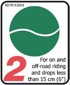
INTENDED USE
The intended use of all models is ASTM Condition 2, that includes Condition 1 as well as unpaved and gravel roads and trails with moderate grades with drops limited to 15 cm.
For information about all ASTM categories, consult the General User Manual.
MAXIMUM NUMBER OF HEADSET SPACERS
Never use more headset spacers below themaximum number of headset spacers that are acceptable for use on an Orbea frame. Installing more spacers than those permitted can stress the materials beyond the use for which they were designed, which can cause accidents and serious injuries.
The length of the fork steerer tube must always be appropriate for the position of the stem in the fork. The stem must always be installed in the steerer tube of the fork so that both fastening bolts on the back of the stem are positioned above the surface of the steerer tube of the fork. Never mount the stem so that the top fastening bolt of the stem remains above the top edge of the fork steerer tube. This will stress the materials beyond the use for which they were designed, possibly causing accidents and serious injuries.
BLUE PAPER KEMEN 2022 16 | ORBEA ORBEA | 17 URBAN/ GENERAL PURPOSE L O.K. NOT O.K. TECHNICAL MANUAL EN
05 USE WARNINGS. PEDELEC SYSTEM COMPONENTS USE AND CARE WARNING OF THE ELECTRIC SYSTEM COMPONENTS AND THE BATTERIES
Read the Relevant Information about the RS Batteries of this manual for more detailed information on the use, care and troubleshooting procedures of the internal battery and Range Extender.
· Do not wash your bike with a pressure washer or submerge it or the electric system components. All the pedelec system components are protected against rain and splashes. However, the use of pressure washers may allow water to ingress into the components and damage them.
· Avoid using your bicycle in extremely adverse weather conditions. All the pedelec system components are protected against rain and splashes. However, very adverse weather conditions may cause water to ingress into the components and damage them.
· Avoid transporting your bicycle outside your car when it is raining. All the pedelec system components are protected against rain and splashes. However, the speed of your vehicle may increase the effects of the rain and damage the components.
If you are transporting your bicycle outside your car, remove the Range Extender from the bicycle and check that the charge port cover is correctly closed.
· Do not leave your bicycle exposed to high temperatures for long periods of time. It may damage the components on your bicycle. Temperatures above 70ºC
· Observe the recommended temperature ranges of use (discharge), charge and storage (internal battery and Range Extender)). The use, charge and storage outside these recommended temperature ranges may affect the battery cells and reduce their life and available range.
The following table shows the maximum and minimum ranges stated by the cell manufacturer.
Generally, the use, charge and storage of batteries below 0ºC will affect the available range for charge of a battery and overtime may reduce the battery life.
TEMPERATURE RANGES
Charge 0ºC - 40ºC
Discharge (Use) -10ºC - 40ºC
Storage 0ºC - 35ºC. Humidity 5%-65%
· Avoid storing your bicycle (internal battery) or Range Extender for long periods of time without monitoring the charge levels.
If planning to store the battery for a long period of time, charge the battery to 50% of its capacity and check the charge level every 3 months (charge it to 50%). Never let the charge level drop below 10% to avoid damaging the cells.
USE OF THE BATTERY BELOW 10% CHARGE:
Avoid discharging your battery regularly below 10% of charge. Charge levels below 10% may affect the life of the cells and the battery balance.
· Avoid leaving the charger connected to the bike continuously for extended periods of time and charge your bicycle or battery in a place where you have visual access to it so the charger can be disconnected if any anomaly
The RS Smart Charger has been designed to stop charging the battery when the charge is completed to avoid damaging the cells for your peace of mind. However, it is recommended to supervise the charge to avoid damages due to a malfunctioning charger.
· Avoid hitting or dropping your battery. If after a fall or an impact the external casing of the battery has been damaged, do not charge or use the battery and contact your authorized dealer for a full diagnosis.
· Always connect the cables following the orientation indications on the connectors. Connecting the cables not following the correct orientation may damage the terminals.
· Before every use, make sure that the charging point cover is installed correctly to avoid dirt or water ingress into the port.
Do not use metallic tools to clean the charging point of foreing objects or dirt. Pay attention not to damage the terminals during this process.
Read the Relevant Information about the RS Batteries of this manual for more detailed information on the use, care and troubleshooting procedures of the RS internal battery and Range Extender.
Consulta de Shimano documentation about the ETEPS EP8 system and its components:
User manual: https://si.shimano.com/api/publish/storage/pdf/en/ um/7HC0B/UM-7HC0B-000-ENG.pdf
Dealer manual:
https://si.shimano.com/api/publish/storage/pdf/en/dm/ EP800/DM-EP800-03_ENG.pdf
RANGE
The Shimano EP8 motor, together with the RS batteries, have been designed to offer the maximum possible rangeable range, will greatly depend on factors such as:
· Assist mode: The use of the more powerful assist modes will decrease the available range.
· Shimano Etube Project app will affect the available level of the assist modes, which may affect the range available.
· Assist modes customization: The approximate range values given below refer to the use of the assist modes as they were originally programmed by Orbea. The customization of the assist modes' power output range of the system.
In order to customise the assist modes on models equipped with the Shimano SCE5003 display, which does not have Bluetooth connectivity, it is necessary to connect the bicycle to the Shimano Etube Project Professional software using the SM-PCE02 interface, since it is not possible to connect the display to the Etube Project Cyclist mobile app. Take your bicycle to an authorised Shimano dealer to perform any changes or replace the original display for a Shimano SCEM800 display.
· Temperature: Charging and using the battery in low temperatures will affect the available range.
· Total weight of cyclist/equipment/luggage.
· Pedal power provided by the cyclist.
· Terrain and climbing: The use on deteriorated roads and routes with considerable altitude gain will affect the available range per charge.
· Frequent stops and accelerations may affect the available range.
BLUE PAPER KEMEN 2022 18 | ORBEA ORBEA | 19 TECHNICAL MANUAL EN
APPROXIMATE RANGE TABLE:
The table below gives approximate range values taking into consideration there is no luggage/load on the carriavailable range as described in the previous section.
INTERNAL BATTERY. 540 Wh
ASSIST MODE ECOTRAILBOOST ACCUMULATED ELEVATION (meters) 3,5002,2001,600
ELECTRIC BICYCLE BATTERY TRANSPORT
The transport of the RS internal battery and the external Range Extender battery should be in accordance with the transport rules and regulations of this type of article. The units must always be transported or sent using the orig-transport from your country's authorities.
If the Range Extender or the internal battery must be sent to Orbea for repairs or diagnosis, it must be in the
06 USE OF KEMEN
This section describes the basic operation of the Shimano STEPS EP8 system on Kemen and the exclusive Orbea components of the pedelec system.
Read the Shimano STEPS EP8 user manual here: https://si.shimano.com/api/publish/storage/pdf/en/ um/7HC0B/UM-7HC0B-000-ENG.pdf
You can access all the user and dealer manuals for Shimano components at: https://si.shimano.com
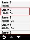
CHECKING THE BATTERY LEVEL
The battery level on Kemen can be checked in different ways, depending on what display option you chose.

COMBINED BATTERY LEVEL OF INTERNAL BATTERY AND RANGE EXTENDER:
When a Range Extender is connected to the bicycle, the system will calculate the combined capacity of both the internal battery and the Range Extender. The remaining battery level shown in the ways below will be the combination of both batteries taking into account the total capacity of the system.
WITH RANGE EXTENDER. 792 Wh (540+252 Wh)
APPROXIMATE RANGE/ ACCUMULATED ELEVATION +50% of range/elevation achieved with the internal battery
equipped for battery shipment. Orbea can inform you of the best option.
If you need the RS batteries safety documentation (MSDS) to ship them or the shipping company asks you for this information, contact Orbea, we will be happy to provide it to you.
ELECTRIC BICYCLE TRANSPORT
If you intend to travel with your electric bicycle, research the transport conditions for batteries according to the airline you plan on using to transport your bicycle. The majority of commercial airlines do not permit transport of batteries with a capacity larger than 100 Wh.
If you need the RS batteries safety documentation (MSDS) to ship them or the shipping company asks you for this information, contact Orbea, we will be happy to provide it to you.
user manual, dealer manual, spare parts, etc.
TURNING KEMEN ON/OFF
To turn Kemen on, press the power button on the lower part of the frame once.
Read the Range Extender external battery section of this manual to learn about the recommended use of the Range Extender on Kemen.
WITH SHIMANO SC-EM800 AND SC-E5003 DISPLAYS
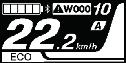
In assemblies with the Shimano SC-EM800 or SC-E5003 displays, the battery(ies) charge level will be shown on the screen.
SC-EM800
100% - 81%
80% - 61%
60% - 41%
40% - 21%
To switch Kemen off, press and hold for 3 seconds the power button on the lower part of the frame until the button´s light fades off.
SC-E5003
20% - 1%
0%
COMPATIBLE GARMIN UNITS. ORBEA RS
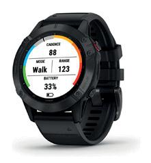
TOOLBOX
you to access relevant information of your Kemen, like the remaining battery level, which is shown as a percentage of the total capacity of the system.
BLUE PAPER KEMEN 2022 20 | ORBEA ORBEA | 21 3 sec. OFF TECHNICAL MANUAL EN
If during an activity the battery level is not visible on Orbea RS Toolbox, the battery level percentage will be visible again when the battery level drops by 1%. At that moment, the EP8 system will communicate the battery level via ANT Private to the Garmin unit and the battery level will be displayed. You can also switch the bicycle off and on again (keeping your Garmin device on) to reset the connection and thus see the battery level on your Garmin device.
Read how to download and install the Orbea RS Toolbox section of this manual.
Range Extender 252Wh.
Press once the main button of the Orbea RS Range Extender for the remaining battery level to be displayed.
The LED lights will show the remaining charge in 25% increments from right to left.
Kemen, Urrun and Rise Hydro 2022 use the same Smart Charger.
To charge the internal battery on Kemen, plug the RS charger into the mains outlet. With the charger not being connected to the bicycle the LED on the charger´s body will blink in blue.
When the battery is fully charged, the charger´s body LED will light in blue permanently.


The Shimano SC-E5003 display does not have ANT Private connectivity, and therefore, models equipped with this display cannot be connected to Garmin devices with
To connect these models to Garmin devices, replace the original display for the Shimano SC-EM800 display.
ORBEA RS BATTERIES
540Wh internal battery.
The internal battery on Kemen does not have LEDs to display the battery level. To know the charge left on the internal battery, it must be connected to the pedelec system in order to check the battery level following the methods described above.
The Kemen 2022 Range Extender battery is not compatible with Rise Carbon 2021-2022 models. The Rise Extender for Rise Carbon 2021-2022 models is not compatible with Kemen 2022.
Kemen, Urrun and Rise Hydro 2022 use the same Range Extender 252Wh 2022 external battery, however, the Range Extender connection cable length is different for each frame. Consult the Range Extender section of this manual.
Read the Range Extender external battery section of this manual to learn about the recommended use of the Range Extender on Kemen.
CHARGING THE BATTERIES
Before using the internal battery or the Range the batteries.
ORBEA RS 540WH INTERNAL BATTERY
The Kemen Smart Charger is not compatible with the Rise Carbon 2021-2022 internal battery or Range Extender.
The Rise Carbon 2021-2022 charger is not compatible with the Kemen internal battery or Range Extender.
Open the bicycle charging port cover and connect the charger aligning the connector correctly. The arrow on the charger connector must be aligned with the top part of the charging port. The charger´s body LED will turn blue for 2 seconds and then it will start fading in and out cyclically until the battery is completely charged.
100%
If the charger´s LED lights in red when connecting the charger to the outlet or during the charging process, there is a charging anomaly. Immediately disconnect the charger and read the charger troubleshooting method in this manual. If the problem persists, contact an authorised dealer.
BLUE PAPER KEMEN 2022 22 | ORBEA ORBEA | 23 TECHNICAL MANUAL EN
ERROR!
Disconnect the charger from the bicycle´s charging port by carefully pulling from the charger´s connector. Make sure the charging port´s cover is correctly closed.
While the charger is connected to Kemen, the bicycle cannot be powered on. If you want to know the exact internal battery level at a given time, disconnect the charger from the bicycle and turn the bicycle on. You will be able to see the battery charge level in the Shimano display..
Avoid discharging your battery repeatedly below 10%.
·Avoid leaving the charger connected to the bike continuously for extended periods of time and charge your bicycle or battery in a place where you have visual access to it so the charger can be disconnected if any anomaly is detected, such as smoke, unusual smells
The RS Smart Charger has been designed to stop charging the battery when the charge is completed to avoid damaging the cells for your peace of mind. However, it is recommended to supervise the charge to avoid damages due to a malfunctioning charger.
To protect the charger and the batteries, the RS Smart Charger disables itself once the battery has been completely charged. If you want to charge the internal battery or
the charger from the mains outlet and plug it again to the outlet to enable the charger. If you have not disconnected the charger from the outlet between charges, the charger may not provide current to the battery.
The lithium-ion batteries are sensitive to temperature during the charging process. Observe the use, charge and storage temperature ranges described in this manual.
RS RANGE EXTENDER BATTERY
The Kemen Smart Charger is not compatible with the Rise Carbon 2021-2022 internal battery or Range Extender. The Rise Carbon 2021-2022 charger is not compatible with the Kemen internal battery or Range Extender. Kemen, Urrun and Rise Hydro 2022 use the same RS Smart Charger.
Read the Range Extender external battery section of this manual to learn about the recommended use of the Range Extender on Kemen.
To charge the Range Extender, plug the RS charger into the mains outlet. With the Range Extender not being connected to the charger, the LED on the charger´s body will blink in blue.
When the battery is fully charged, the charger´s body LED will light in blue permanently.


Avoid discharging your battery repeatedly below 10%.


·Avoid leaving the charger connected to the bike continuously for extended periods of time and charge your bicycle or battery in a place where you have visual access to it so the charger can be disconnected if any anomaly
100%
While the Range Extender is being charged, the charge indicator LEDs will show the current battery level. The blinking LED shows the range (in 25% increments) that is currently being charged.
The RS Smart Charger has been designed to stop charging the battery when the charge is completed to avoid damaging the cells for your peace of mind. However, it is recommended to supervise the charge to avoid damages due to a malfunctioning charger.
To protect the charger and the batteries, the RS Smart Charger disables itself once the battery has been completely charged. If you want to charge the internal battery the charger from the mains outlet and plug it again to the outlet to enable the charger.
Disconnect the Range Extender connection cable to the bicycle charging port (in case it is connected) by turning
pulling from the cable. Connect the charger to the Range Extender correctly aligning the connector pins with those of the Range Extender´s charging port. The charger´s body LED will turn blue for 2 seconds and then it will start fading in and out cyclically until the battery is completely charged.
When the battery is fully charged, disconnect the charger from the charging port by carefully pulling from the charger connector.
If you are going to use the Range Extender on the bicycle, connect the Range Extender cable to the Range Extender and the bicycle charging port with the safety tabs open and, once the cable is correctly connected, turn the tabs clockwise for a safe connection.
If you have not disconnected the charger from the outlet between charges, the charger may not provide current to the battery.
The lithium-ion batteries are sensitive to temperature during the charging process. Observe the use, charge and storage temperature ranges described in this manual.
Read the Relevant Information about the RS Batteries of this manual for more detailed information on the use, care and troubleshooting procedures of the RS internal battery and Range Extender.
BLUE PAPER KEMEN 2022 24 | ORBEA ORBEA | 25 TECHNICAL MANUAL EN
CHANGING THE ASSIST MODE
To change between assist modes with the SW-EM800 (assemblies with SC-EM800 display) or the SC-E5003 display, press the X button to increase the assist mode up until the maximum available (Boost). Press the Y button to decrease the assist level until the no-assist mode is reached.
The available assist modes are:
· OFF (no electric assist)
· ECO
· TRAIL
· BOOST
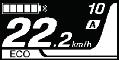
The SC-EM800 display will show the name of the selected assist mode on the screen. The SC-E5003 display will show the selected assist mode by means of the bars on the left of the screen. The more segments are lit up (maximum 3), the more powerful the selected assist mode.
WALK ASSIST
To activate Walk Assist, press the SW-EM800 remote lever or the SC-E5003 display button Y for 1 second until the word WALK appears on the EM800 display or the walk assist symbol is visible on the E5003 display.
Release the Y button and press it again to engage Walk Assist. The system will help you push the bike along as long as the Y button is pressed.
Read the Shimano SC-E5003 display here:
https://si.shimano.com/api/publish/storage/pdf/en/ um/7HU0B/UM-7HU0B-000-ENG.pdf
Read the Shimano SC-EM800 display here:
https://si.shimano.com/api/publish/storage/pdf/en/ um/7H90B/UM-7H90B-001-ENG.pdf
The power delivery levels of each assist mode can be customised using the Shimano Etube Project Cyclist smartphone app to adjust Kemen to your needs.
The Shimano EP8 motor allows you to choose between
Project Cyclist smartphone app.
Read the Shimano Etube Project Cyclist app section of this manual to learn about how to change between the assist
Read the complete Shimano Etube Project Cyclist app manual on the link below:
https://si.shimano.com/#/en/iUM/7J4MA

Models equipped with the Shimano SCE5003, which does not have Bluetooth connectivity, cannot be connected to the Etube project Cyclist app to customise the assist modes. If you wish to customise the power delivery of the assist modes on these models, take your bike to an authorised Orbea or Shimano dealer to connect the system to the Etube Project Professional software using the SM-PCE02 interface and make the necessary changes or replace the original display for the Shimano SC-EM800 display.
er the greatest optimal assist power for each assist level.
quire less assistance from the system and therefore will demand greater input from the rider.
In case a Range Extender RS external battery is connected to Kemen, it is not recommended to customise the assist levels parameters through the Shimano Etube Project Cyclist app or Etube Project Professional. Read the Range Extender section of this manual to learn more.
TURNING THE LIGHTS ON/OFF
Read the Lights section of this manual to know more about the lights on Kemen.
RUNNING LIGHTS
Turn the bicycle on by pressing the system´s power button. The front running light (integrated in the headset cover) and the rear running light (on the mudguard blade or on the rack on SUV models) will turn on automatically.
The headset cover front running light can be switched off by pressing the button on the left side of the cover.
The rear running light cannot be switched off while the bicycle is on.
If the bicycle is switched off, the running lights will turn off automatically.
REAR RUNNING LIGHT BEHAVIOUR WHEN BRAKING:
The Kemen rear running light has an accelerometer that makes the light brighter when the speed is reduced suddenly.
It cannot be considered a brake light since the light is not connected to the brake lever.
LEZYNE FRONT LIGHT
Having turned the bicycle on, press and hold the handlebar remote button to turn on the Lezyne front light (the light model changes depending on the Kemen model).
With the front light on, a short press of the handlebar remote button will change the light output between high beam and low beam.
To switch the front light off, press and hold the handlebar remote button.
When the bicycle is switched off, the front light will turn off automatically.
BLUE PAPER KEMEN 2022 26 | ORBEA ORBEA | 27 Y (1 sec) SC-EM800 SC-E5003 Y (Press&Hold) WALK X Y OFF > ECO > TRAIL > BOOST BOOST > TRAIL > ECO > OFF SC-EM800 SC-E5003 TECHNICAL MANUAL EN
-
-
LEZYNE FRONT
ALWAYS ON
It will be necessary to switch the lights on through the
Read the Connection to Etube Professional section of this manual to know how to connect Kemen to Etube Professional using the Shimano SM-PCE02 interface.
REMOTE ON ON REMOTE OFF OFF 1 SEC 1 SEC MODE HIGHBEAM
SWITCHING THE LIGHTS ON/OFF WITH THE SHIMANO DISPLAY (Option not active)
The lights cannot be switched on/off through the Shimano displays.
If you wish to activate this function, take your bicycle to an authorised Shimano dealer. They can connect the system
LOWBEAM


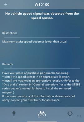
SYSTEM WARNINGS/ ERRORS
When an error or warning is detected in the system, the SC-EM800 or SC-E5003 displays will show the warning or error code on the screen.
OPTION NOT ACTIVE
See Connection to Etube

Professional section
to the Etube Project Professional tool using the Shimano SM-PCE02 interface to change the lighting option from ALWAYS ON to BUTTON.
With the BUTTON option selected, the running light will no longer turn on automatically when the bicycle is switched on and the Lezyne front will not be active.
Turn the bicycle Off and On again and connect it to the Shimano Etube Project app. The error or warning code and the troubleshooting procedure will be shown in the section Maintenance>Error Log.

You can also consult the EP8 system manual for the error codes and their solutions.
ERROR WARNING
The Shimano SC-E5003 display does not have Bluetooth connectivity, and therefore you will not be able to connect the bicycle to the app on models with this display. To know the troubleshooting procedure for an error or a warning, consult the code in the Shimano STEPS user manual or take your bicycle to an authorized Shimano dealer to have it diagnosed or replace the original display for the Shimano SC-EM800 display.
1 SEC
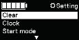
Clock Start mode Lights


Off On SC-EM800
Rear the full Shimano STEPS warning and error code list and troubleshooting procedure in the following link:
https://si.shimano.com/iER/STP0A

BLUE PAPER KEMEN 2022 28 | ORBEA ORBEA | 29
SC-EM800 SC-E5003
BIKE ON FRONT ON REAR ON FRONT OFF
DAYLIGHTS
ON/OFF
SC-E5003 TECHNICAL MANUAL EN
07 SHIMANO ETUBE PROJECT CYCLIST
CUSTOMIZATION OF THE EP8 SYSTEM
Models equipped with the Shimano SCE5003 display, which does not provide Bluetooth connectivity, cannot be connected to the Etube Project Cyclist smartphone app to customise the assist mode's power levels. If you wish to modify the assist levels, take your bicycle to an authorised Shimano dealer to connect it to the Shimano Etube Professional tool using the SM-PCE02 interface and make the necessary changes or replace the original display for the Shimano SC-EM800 display. -
er the greatest optimal assist power for each assist level. -

quire less assistance from the system and therefore will demand greater input from the rider.
In case a Range Extender RS external battery is connected to Kemen, it is not recommended to customise the assist levels parameters through the Shimano Etube Project Cyclist app or Etube Project Professional. Read the Range Extender section of this manual to learn more.
Using the Shimano Etube Project Cyclist app for smartphones, you can customise the EP8 system to adjust Kemen to your needs.
power for your riding style.
The EP8 motor also allows the selection of two different that you need in every situation.
Consult the complete Etube Project Cyclist app manual on Shimano´s website. Etube Project Cyclist also lets you customise the remote lever buttons, view error reports, up-
Read the complete app manual here:
https://si.shimano.com/#/en/iUM/7J4MA
Download and install Etube Project Cyclist on your smartphone from Google Play or the Apple Store.
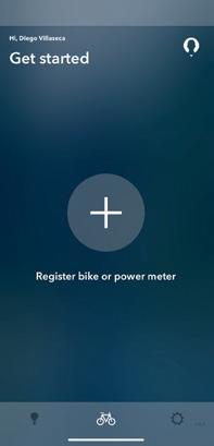
1.Open Etube Project on your smartphone.
Turn your bicycle on and run the app on your phone.
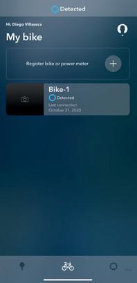
2.Select Register Ebike.
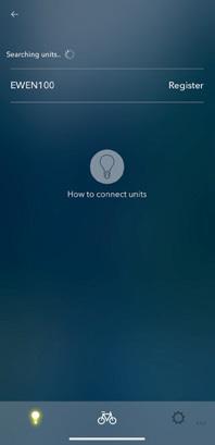
3.Select the unit to pair.
If the unit is not visible on the screen after a few seconds, press one of the handlebar assist mode remote switch buttons to activate the connection.

4.Register your bike on Etube Project. Choose to change the pass key so only you can make changes to your bicycle. If you do not wish to change the pass key, continue to the next step.
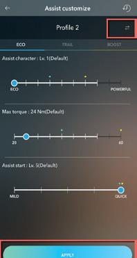
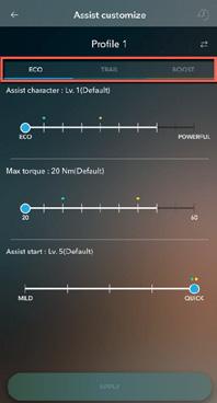
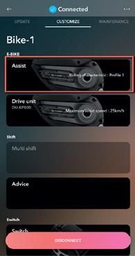
5.Select Assist from the Customise tab.
6.Change the maximum torque and the assist charyour activity.
system using Etube Project.
visible on the app´s screen before disconnecting the bicycle.
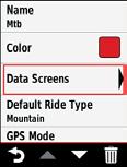
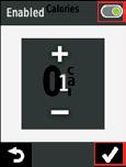
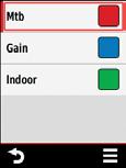
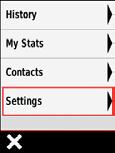
On models equipped with the Shimano SC-EM800 disdisplay´s menu (besides using the Etube Project Cyclist app as described above).
BLUE PAPER KEMEN 2022 30 | ORBEA ORBEA | 31 2 3 5 6 4 7 TECHNICAL MANUAL EN
·Setting menu screen (press and hold the display button)lected during an activity using the handlebar remote lever.
Models equipped with the Shimano SCE5003 display, which does not provide Bluetooth connectivity, cannot be connected to the Etube Project Cyclist smartphone
SC-E5003 display either. If you wish to seassist levels, take your bicycle to an authorised Shimano dealer to connect it to the Shimano Etube Professional tool using the SM-PCE02 interface and make the necessary changes or replace the original display for the Shimano SC-EM800 display.
Read the Shimano SC-EM800 and SC-E5003 displays manuals on Si.Shimano:
https://si.shimano.com/#/
Or access the manuals directly: Shimano SC-EM800 display manual: https://si.shimano.com/api/publish/storage/pdf/en/ um/7H90B/UM-7H90B-001-ENG.pdf
Shimano SC-E5003 display manual: https://si.shimano.com/api/publish/storage/pdf/en/ um/7HU0B/UM-7HU0B-000-ENG.pdf
SYSTEM ERRORS
If there are any errors in the system, Etube Project Cyclist allows you to access the Error Log, where you can see the error codes and their troubleshooting procedure.
Read the “System errors and warnings” section in the Use of Kemen chapter of this manual to know how the system shows current errors and warnings, the different error codes and their troubleshooting procedure.
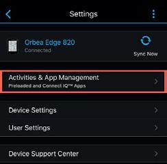
08 ORBEA RS TOOLBOX
DATA FIELD FOR GARMIN DEVICES
INSTALL AND UNLOCK ORBEA RS TOOLBOX ON GARMIN DEVICES. GARMIN EXPRESS (PC/MAC)
devices exclusive for owners of Orbea ebikes equipped with the Shimano EP8 system. It is added to your Garmin information about your bicycle while riding.
Models equipped with the Shimano SCE5003, which does not have ANT Private connectivity, cannot be connected to Garmin devices where the Orbea RS Toolbox
To connect these models to Garmin devices, it is necessary to replace the SC-5003 display for the Shimano SC-EM800 display.
The unlocking and downloading of Orbea RS Toolbox on compatible Garmin devices must be done using the PC/Mac program Garmin Express as described in the method below.
IT IS NOT POSSIBLE TO UNLOCK AND DOWNLOAD RS TOOLBOX USING GARMIN CONNECT SMARTPHONE APP.
Download and install Garmin Express for PC or Mac: www.garmin.com/en-US/software/express/windows/

Your computer must have an active Internet connection to complete the unlock and download process.
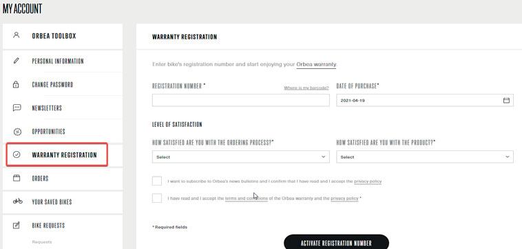
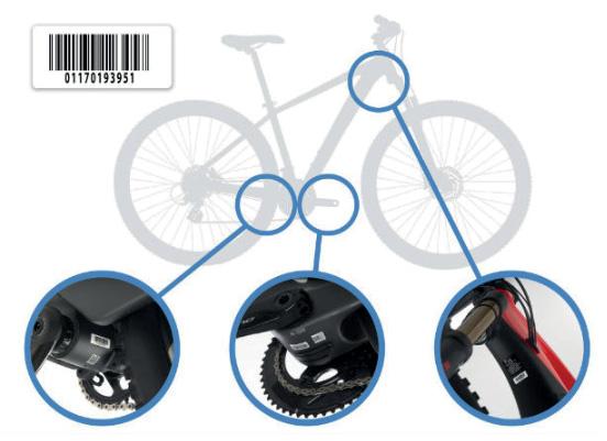
To unlock Orbea RS Toolbox on your Garmin device, you must have registered your new bicycle’s barcode on Orbea’s website, which also lets you enjoy the Life Warranty on your new frame. Go to Orbea’s website and register your bike’s barcode, creating an account
www.orbea.com/us-en/access-register
BLUE PAPER KEMEN 2022 32 | ORBEA ORBEA | 33 TECHNICAL MANUAL EN
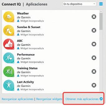
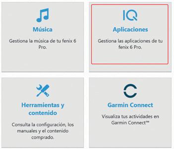
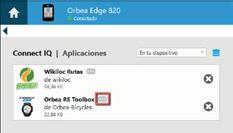
4. Select “Applications”.
the bicycle’s frame:
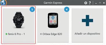
1. Connect your Garmin device to your PC or Mac using the cable included with your device.
2. Execute Garmin Express on your computer.
5. Select “Get more apps”.
6. The Internet browser will open Garmin Connect IQ. Search for and select Orbea RS Toolbox in Connect IQ.

If you cannot see the app Orbea RS Toolbox in the IQ Store, your device is not compatible with the app. We are working to include new devices every day, contact Orbea if you need more information.
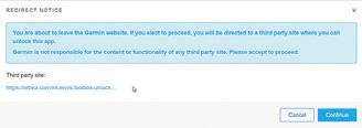
7. Select “Unlock” RS Toolbox.
8. Accept to continue on to the Orbea´s website to unlock your device.


3.Select the device you want to install RS Toolbox on.
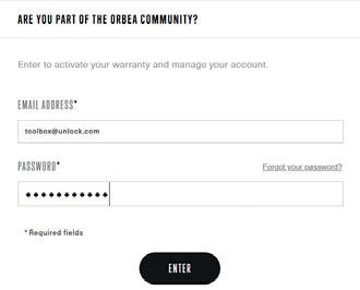
9. On Orbea´s website, introduce your user account login details.

10. If you had previously registered an EP8 equipped Orbea bicycle onto your account, the website will let you know that your device has been successfully unlocked.

BLUE PAPER KEMEN 2022 34 | ORBEA ORBEA | 35 7 6 8 9 10 TECHNICAL MANUAL EN
11. Go back in the browser to the RS Toolbox page in the Garmin IQ Store.
12. In the RS Toolbox page on Connect IQ, you will see that the “Unlock” button has disappeared. Orbea RS Toolbox has been unlocked.
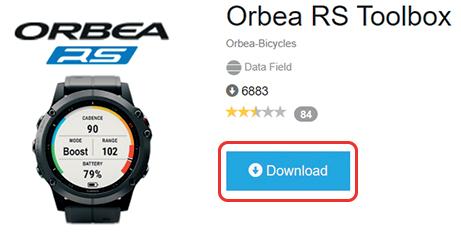

Click ”Download” to install RS Toolbox on your device.
·If the “Unlock” button is still visible, RS Toolbox has not been unlocked. Do not click “Download”. Restart again the unlock process.
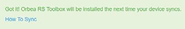
13. A message will let you know that RS Toolbox has been downloaded successfully, and that it will be installed next time your device is synchronised.
14. Exit the Internet browser and open Garmin Express. Your device should synchronise automatically. If it does not, synchronise your device before disconnecting your device from your computer.
Disconnect your device from your computer.
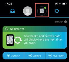
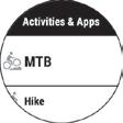
If you have downloaded and installed on your smartphone the Garmin Connect app from Google Play or Apple Store, pair your device to the app and select your device in the top right hand corner of the screen. You can access Orbea RS Toolbox on:
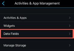
Activities, Apps & More > Data Fields
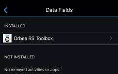
If Toolbox is visible but it is not installed, synchronise your device.
Go to the next section to know how to visualise RS Toolbox on your device.
ENABLING ORBEA RS TOOLBOX IN YOUR DEVICE
After downloading and unlocking Toolbox through Garmin Express (PC or Mac) and synchronising your Garmin unit,

on both Garmin Edge and watches compatible units.
Orbea RS Toolbox is not compatible with the use of the Garmin Edge Shimano STEPS native app on Edge 530, 830, 1030, and 1030 Plus devices. Disconnect or delete your bicycle from the sensors list of your Edge unit before trying to connect Orbea RS Toolbox. This limitation does not come from Toolbox, but from Garmin.
BLUE PAPER KEMEN 2022 36 | ORBEA ORBEA | 37 11 12 13 14 TECHNICAL MANUAL EN
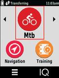
1. Turn on your Kemen and the unit you have installed Orbea RS Toolbox on, they will pair automatically.
2. Kemen with.
Garmin Edge units
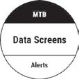
4. Scroll through the data to be seen on the screen. Select Connect IQ and choose Orbea RS Toolbox.
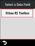


If you had not connected your Kemen before setting up Toolbox on your device, the unit will show the message “Searching…” after selecting the Orbea RS

access the page where you chose to see Toolbox, the data from your Kemen will be visible.


If after selecting Orbea RS Toolbox the screen shows the message “Unlock in Connect IQ”, the downloaded version has not been correctly unlocked. Connect your device to your computer and restart again the Unlocking and Downloading procedure through Garmin Express as described in the previous section.
3.
on which you want to see the data from your Kemen. on the page.
Garmin watches
Garmin Edge units

5.
which you selected to see the data from Toolbox or start unit. Navigate to the page you selected to see Toolbox on to access the real-time data from your bicycle.


Garmin watches
Garmin watches
BLUE PAPER KEMEN 2022 38 | ORBEA ORBEA | 39 TECHNICAL MANUAL EN
Garmin Edge units
Garmin Edge units
Garmin watches
USING ORBEA TOOLBOX
Orbea RS Toolbox is not compatible with the use of the Garmin Edge Shimano STEPS native app on Edge 530, 830, 1030, and 1030 Plus devices. Disconnect or delete your bicycle from the sensors list of your Edge unit before trying to connect Orbea RS Toolbox. This limitation does not come from Toolbox, but from Garmin.
CONNECT YOUR BICYCLE TO ORBEA RS TOOLBOX
Always turn your Garmin on and start recording an activity and then turn your bicycle on for the remaining battery
Otherwise, the remaining battery level will be displayed when some distance has been covered and the battery level drops by 1%.
When starting Toolbox, it will connect to the bike with the strongest signal (normally the closest one) and, once connected, it will stay paired to that bike. If you are experiencing pairing problems, make sure your bicycle is the only bicycle turned on to make the connection easier.
The bicycle and Toolbox will connect via ANT Private automatically. If the data from your bicycle is not shown in

Toolbox, try to change assist levels with the handlebar remote. If the Toolbox data is still not visible, switch the bicycle off and turn it back on to reset the connection. your bicycle.
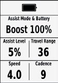
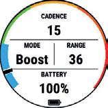
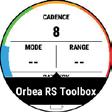
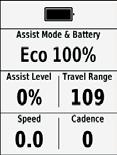
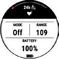
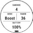
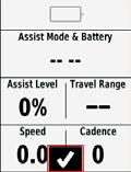
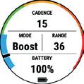
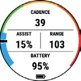
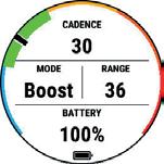
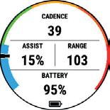
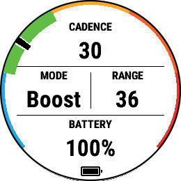
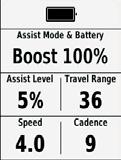
AVAILABLE INFORMATION IN ORBEA RS TOOLBOX
ASSIST MODE: Shows the currently selected assist mode from the modes available: Off, Eco, Trail, Boost.
· Assist mode visualization options (on Garmin watches): Orbea RS Toolbox allows you to see the currently selected assist mode in two different ways. Read the Data Fields Customization section of this manual to

. You can choose to see the selected assist mode on the name of the selected mode.
BLUE: Walk Assist selected but not active.
GREEN: Walk Assist active.

YELLOW: Eco.
ORANGE: Trail.
RED: Boost.
. You can choose the assist level to be shown on the external colour band around the screen. Thus, the current assist level will be displayed by a black line that will travel through the motor power range (1%-100%).
Walk Assist Active
Walk Assist
Eco Trail Boost
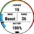
BATTERY: Charge level of the battery shown as a percentage.
If an external RS Range Extender battery is connected, the system will account for the total capacity of both the internal battery and the Range Extender (612 Wh) and Toolbox will show the percentage of battery charge remaining based on the total capacity of the system.
If while using the bicycle the battery percentage level is not visible in Toolbox, the information will be visible again when the battery level drops by 1%. At that moment the Ep8 system will send the remaining battery level information via Bluetooth to the Garmin device and the battery level will be shown in the unit.
areas of the engine power range. For example, only the more powerful assist modes will allow the motor to deliver power around its 100% potential.
. It is also possible to see the selected assist modes on the external colour band around the screen. When selecting an assist mode, the corresponding area will be highlighted. The assist modes colour codes are :
ASSIST LEVEL: Assist power delivered by the motor depending on the assist mode selected. It is shown as a percentage of the total power available from the motor.
· Assist level visualization options (on Garmin watches): Orbea RS Toolbox allows the assist level to be shown in two different ways. Read the Data Fields Customization section of this manual to learn how to select
Walk Assist Active
. It is also possible to select the assist level to be shownred as a percentage of the total power available from the motor. Walk Assist
Eco Trail Boost
RANGE: Available range (in km or miles) in the selected assist mode with the remaining battery charge. The range shown may change depending on the power delivered by the rider, as well as the previous use of the bicycle.
SPEED: The bicycle´s current speed.
CADENCE: The rider´s pedalling cadence.
BLUE PAPER KEMEN 2022 40 | ORBEA ORBEA | 41 TECHNICAL MANUAL EN
1%-20% 21%-40% 41%-60% 61%-80% 81%-100% Current power delivery
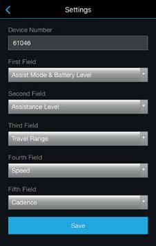
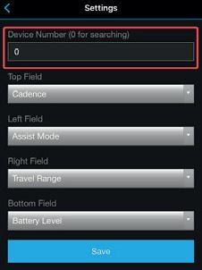
DATA FIELDS CUSTOMIZATION
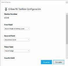
The order in which the system data is shown in Toolbox can be changed using Garmin Express (PC or Mac) or the Garmin Connect app (smartphones).
1. Open Garmin Connect on your smartphone and connect your Garmin device.
2. Access your device through the app and navigate to the Orbea RS Toolbox Setting menu: Apps Management > Data Fields > Orbea RS Toolbox> Settings
3. drop menus and press Save.
If the unit was connected to the bicycle when you saved the changes, you will see immediately the changes after you synchronise your device
GARMIN EXPRESS (PC AND MAC)
application Garmin Express for PC and Mac. Connect your Garmin unit to your computer using an USB cable and access Installed Apps. Press the Orbea RS Toolbox Setting button and select what information you want to see in
4. Go back to the Connect main screen and synchronise your device.
5. Follow the method to connect to a different bicycle as described in the section above. You must follow this method every time you need to connect to a different bike.
If the pairing does not work with the new bike, uninstall Toolbox from your device and install it again using The Garmin Connect app and try to pair the new bike again. your device.
ACTIVITY DATA RECORDING OF KEMEN IN GARMIN CONNECT
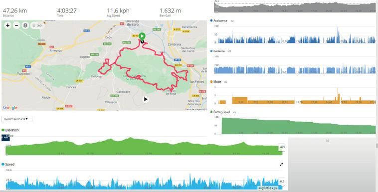
When you record an activity using Orbea RS Toolbox in your Garmin device, the data from Toolbox are recorded along with the rest of the data from your device. Thus, you can later access the Toolbox data, such as assistance level, range, battery charge level, cadence, etc. as part of the data from the recorded activity.
Access through Garmin Connect the data from Orbea RS Toolbox during a recorded activity the same way you access the rest of the data recorded by your device during the activity.
CONNECTION TO ANOTHER BICYCLE
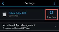
4. Go back to the main app screen and select Sync Now.
When you connect your Garmin unit to your bicycle, the data will be displayed according to your saved selection.
Once you have RS Toolbox installed and visible on your Garmin device, you will be able to connect to any other Orbea bicycle with Shimano EP8 motor and ANT Private connectivity.
1. Open Garmin Connect on your smartphone and connect your device.
2. Access your device through the app and navigate to the RS Toolbox Settings menu: Activities, apps & more > Data Fields > Orbea RS Toolbox > Settings
3. changes.
BLUE PAPER KEMEN 2022 42 | ORBEA ORBEA | 43 TECHNICAL MANUAL EN
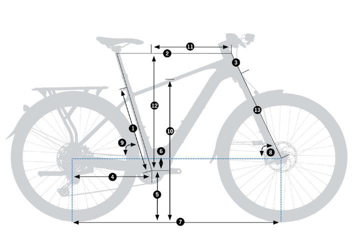
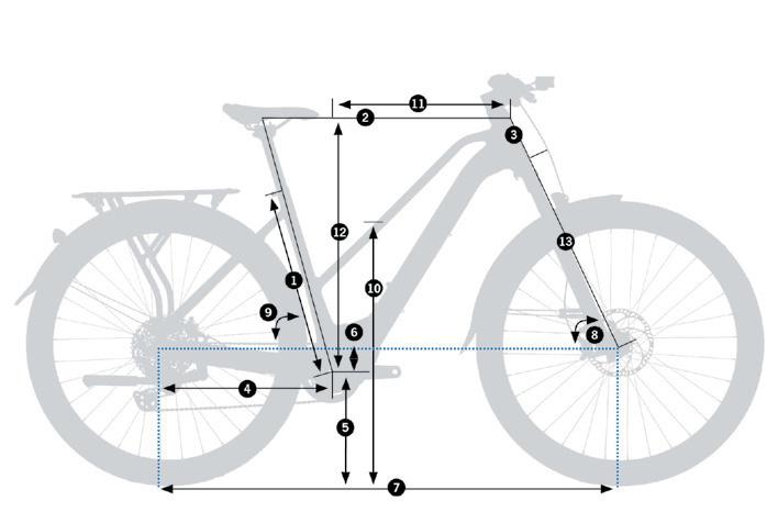
BLUE PAPER KEMEN 2022 44 | ORBEA ORBEA | 45 KEMEN KEMEN MID TECHNICAL MANUAL EN 09 GEOMETRY AND SIZING HEIGHT(CM)HEIGHT(IN)SIZE* 155-17061.1”-66.9”S 165-18065.0”-70.9”M 175-19070.1”-74.8”L 185-20072.8”-78.74”XL
1 - Seat Tube (C-T) 400453483533 2 - Top Tube (EFF) 563576606642 3 - Head Tube 110115132153 4 - Chainstay 445445445445 5 - BB Height 307,5307,5307,5307,5 6 - BB Drop 63636363 7 - Wheelbase 1134114211731211 8 - Head Angle 66,5º67º67º67º 9 - Seat Angle 75º75º75º75º 10 - Standover 781810833866 10 - MID BAR Standover 73274074311 - Reach 405415440470 12 - Stack 617624640659 13 - Fork Length 513,5513,5513,5513,5 * These sizing measurements are an approximate guide. The most effective method to choose the right size for you is to try the bicycle at one of our authorized dealers.
SIZEDSMLXL
MAXIMUM AND MINIMUM SADDLE HEIGHT WITH DROPPER SEATPOSTS
Find below a table with the maximum and minimum possible height with the seatpost in its extended position.
The maximum height refers to the seatpost installed in its
The minimum height refers to the seatpost installed in its
Only the measurements with the seatpost and saddle options offered by Orbea for a given frame are listed. To know these measurements for any other seatpost brand and model, consult the seatpost dimensions with the manufacturer and check the maximum insertion for each size frame on this manual.
The measurements given show the distance between the center of the bottom bracket shell to the middle of the saddle´s top (saddle
Different saddle models in the market may vary these heights by +/-5mm depending on the saddle model height. If your saddle height differs from the values on the table by less than 5mm, it may be possible to adjust the height by means of an aftermarket saddle of a different height.
If your saddle height differs from the values on the table by more than 5mm, choose a longer or shorter travel seatpost.
OC DP-MC20
31.6
50mm
OC DP-MC20
31.6
75mm
OC DP-MC20
31.6
100mm
OC DP-MC20
31.6
125mm
OC DP-MC20
31.6
150mm
OC DP-MC20
31.6
170mm
Minimum saddle height. Extended 570mm*619mm*649mm*701mm*570mm*619mm*649mm*
Maximum saddle height. Extended 649mm*699mm*726mm*780mm*649mm*699mm*726mm*
Minimum saddle height. Extended 594mm*644mm*674mm*725mm*594mm*644mm*674mm*
Maximum saddle height. Extended 669mm*722mm*752mm*806mm*669mm*722mm*752mm*
Minimum saddle height. Extended 619mm*670mm*709mm*751mm*619mm*670mm*709mm*
Maximum saddle height. Extended 720mm*773mm*804mm*854mm*720mm*773mm*804mm*
Minimum saddle height. Extended 657mm*696mm*724mm*776mm*657mm*696mm*724mm*
Maximum saddle height. Extended 770mm*821mm*852mm*902mm*770mm*821mm*852mm*
Minimum saddle height. Extended 706mm*719mm*752mm*800mm*706mm*719mm*752mm*
Maximum saddle height. Extended 819mm*873mm*901mm*952mm*819mm*873mm*901mm*
Minimum saddle height. Extended 746mm*746mm*770mm*821mm*746mm*746mm*770mm*
Maximum saddle height. Extended 858mm*912mm*945mm*996mm*858mm*912mm*945mm*
* The measurements may vary +/-5mm depending on the height of the saddle model.
BLUE PAPER KEMEN 2022 46 | ORBEA ORBEA | 47 MAX MIN TECHNICAL MANUAL EN
DROPPER SEATPOST SADDLE HEIGHT EXTENDED KEMEN TOP (S) KEMEN TOP (M) KEMEN TOP (L) KEMEN TOP
KEMEN MID (S) KEMEN MID (M) KEMEN MID (L)
FRAME/SIZE
(XL)
TECHNICAL SPECIFICATIONS
TECHNICAL SPECIFICATIONS. KEMEN
FRAME MATERIAL Hydroformed aluminum 6061. Triple butted
INTENDED USE
SIZES
ASTM Condition 2. E-URBAN/ALL PURPOSE
Top Bar: S, M, L, XL Mid Bar: S, M, L
FORK TRAVEL 100 mm. Limited by mudguard. (120mm without mudguard. With 120mm fork)
MAXIMUM FORK LENGHT (AXLE-TO-CROWN) 515 mm. Limited by mudguard. (535mm without mudguard)
FORK OFFSET 44 mm
HEADSET Orbea ICR HS01. Internal Cable Routing
HEADSET BEARINGS
Upper 1" 1/2 (with 1-1/2" to 1-1/8" adapter for internal cable routing)
Lower 1" 1/2
MAXIMUM HEADSET SPACERS STACK 20 mm
HANDLEBAR OC HB-MP31. STEPS and light remote internal cable routing
BOTTOM BRACKET
CHAINLINE
Shimano EP8 motor axle
Boost. 53mm
WHEEL SIZE 29"
Asphalt models: (Apollo 65mm mudguards) 29x2.2"
Maximum tyre external diameter: 741 mm
Maximum tyre width: 55 mm
SUV models: (Apollo 70mm mudguards) 29x2.35"
Maximum tyre external diameter: 750 mm
COMPATIBLE
BRAKES
EP8 axle spline. 11-12S. 53mm chainline
MAXIMUM TYRE WIDTH
Maximum tyre width: 62 mm
Without mudguards
Rear: 29 x 2.6"
Maximum tyre external diameter: 758 mm
Maximum tyre width: 64 mm
Front: Depends on fork.
Fox 34 & Marzocchi Bomber Z2: 29 x 2.4"
SPEED SENSOR MAGNET PLACEMENT** On rear disc brake rotor (see Pedelec System Components section)
REAR
FRONT ROTOR MAXIMUM SIZE Depends on fork. Fox 34 2022/Marzocchi Bomber Z2: 180 mm
FRONT ROTOR MINIMUM SIZE Depends on fork. Fox 34 2022: 180mm. Marzocchi Bomber Z2: 160 mm
COMPATIBLE CHAINGUIDE
Yes. Shimano E8000-EP8 motor compatible chainguide Orbea assemblies without chainguide. For aftermarket options, a chainring without a bashguard may be needed
ICGS No
Rear brake and derailleur: Internal through headset, downtube and chainstays. Full housing
Ebike system: Internal through headset, downtube and chainstays.
CABLE ROUTING
Dropper seatpost: Internal through headset, downtube and seat tube. Full housing
Lights: Front: Internal through headset and downtube. Rear: Through channel along the rear mudguard.
Mid Bar: 1. All sizes (downtube). Range Extender holder or standard bottle holder
BOTTLE HOLDER
Top Bar: 2. All sizes.
Downtube: Range Extender holder or standard bottle holder. Seat tube: Standard bottle holder only
DRIVETRAIN COMPATIBILITY
MTB. 10S, 11S and 12S
BLUE PAPER KEMEN 2022 48 | ORBEA ORBEA | 49 TECHNICAL MANUAL EN 10
AXLE
Boost
AXLE MEASUREMENTS 12x180
AXLE THREAD PITCH 1.5 mm REAR AXLE THREAD LENGTH 14 mm SEATPOST DIAMETER 31.6 mm SEATPOST CLAMP DIAMETER 34.9 mm MAXIMUM SEATPOST INSERTION TOPBAR S 220 mm TOPBAR M 270 mm TOPBAR L 305 mm TOPBAR XL 353 mm MIDBAR S 237 mm MIDBAR M 275 mm MIDBAR L 305 mm DROPPER SEATPOST INTERNAL CABLING COMPATIBLE Yes FRONT DERAILLEUR No. Only 1X COMPATIBLE CHAINRINGS
CHAINRING SIZE 44T
30T
STANDARD
12x148 REAR
mm REAR
With Shimano
MAXIMUM
MINIMUM CHAINRING SIZE
OVAL CHAINRING No
Disc*/**
180
REAR BRAKE CALIPER STANDARD Post Mount REAR ROTOR MAXIMUM SIZE
mm
160
REAR ROTOR MINIMUM SIZE
mm
TECHNICAL SPECIFICATIONS. KEMEN
COMPATIBLE SHIMANO DI2 Yes. Rear derailleur
COMPATIBLE SRAM AXS
Yes. Dedicated freehub body
COMPATIBLE POWERMETER No
Yes. Compatible with standard rear racks
Asphalt models: 18 Kg Max.
TECHNICAL SPECIFICATIONS
SHIMANO EP8 -
Consult the Shimano EP8 system information in the manufacturer´s documentation.
https://si.shimano.com/api/publish/storage/pdf/en/dm/ EP800/DM-EP800-03_ENG.pdf
You can access all Shimano dealer´s and user´s manuals at Si.Shimano. Type the component´s name in the search
formation: https://si.shimano.com
The RS internal battery and Range Extender are Orbea´s own.
REAR RACK ASSEMBLY
Consult Rear Rack section of this manual
SUV models: 27 Kg Max. MIK HD system
SHIMANO EP8 RS MOTOR
NOMINAL POWER 250W
KICKSTAND ASSEMBLY Yes. Ursus Mooi
MUDGUARDS ASSEMBLY Compatible. See mudguards section
CHILD SEAT COMPATIBILITY
See rear rack section of this manual
MAXIMUM STRUCTURAL WEIGHT LIMIT (rider+gear+luggage)
Asphalt models: No. Original rear rack not compatible.
SUV models: Yes. On original MIK HD rear rack. Max 27 Kg.
Consult the Orbea Products Structural Weight Limit document on Orbea´s website
REAR TRAILER COMPATIBILITY Yes. See details***
* Not all calipers and rotors in the market are compatible with all For aftermarket options, check componentes dimensions and tolerances befores purchasing.
** Orbea assemblies are equipped with Magura disc brakes. The brake hoses angle at the levers on Magura brakes allow the hoses to run closer to the handlebar for a cleaner look. Kemen is compatible with other disc brake lever models, however different hose angles at the levers may affect the cable routing and make the hoses more visible.
· DISC BRAKE ROTORS COMPATIBILITY: Read the Pedelec System Components section to know more about the rear rotor compatibility.
*** REAR TRAILER COMPATIBILITY: The table below shows the rear axle trailer models with which the frame is compatible. Orbea do not sell these references, and cannot be held responsible for their future availability or possible incompatibilities due to
VOLTAGE 36V TYPE Brushless DC
MAXIMUM TORQUE 85 N.m
MAXIMUM SPEED 25 Kph (EU) 20 Mph (US)
WEIGHT 2.6 Kg
ASSIST PROFILES 2 (Selectable through the Etube Project app or the Shimano SC-EM800 display)
ASSIST LEVELS (PER PROFILE) 3 (ECO, TRAIL, BOOST) Customizable through the Etube Project app
WALK ASSIST Yes
STEPS/DI2 CABLING STANDARD
EW-SD300
LIGHTS CONNECTION Yes. 12V DC. Read the Lights section of this manual
MOTOR ASSEMBLY ANGLE 32º
SC-EM800 DISPLAY (SELECTED MODELS)
FUNCTIONS
TRAILER MANUFACTURER AXLE MEASUREMENTS MANUFACTURER´S AXLE REFERENCE COMPATIBLE TRAILER MODELS ASSEMBLY INSTRUCTIONS
THULE M12 x 178 x 1,520110734Contact ThuleContact Thule
FOLLOW ME M12 x 178 x 1,5121125Contact Follow MeContact Follow Me
BURLEY M12 x 178 x 1,5960121Contact BurleyContact Burley
CROOZER M12 x 178 x 1,5122500418Contact CroozerContact Croozer
HAMAX 148 mm M12xP1.5 mm936012Contact HamaxContact Hamax
CONNECTIVITY
Charge level display
Assist level display
Error display
Lights On/Off (see Lights section)
Bluetooth LE (Shimano Etube Project app): Yes
ANT Private: Yes
ASSEMBLY Handlebar (35mm clamp)
STEPS/DI2 CABLING STANDARD
EW-SD300
MANUFACTURER´S MANUAL https://si.shimano.com/api/publish/storage/pdf/en/um/7H90B/UM-7H90B-001-ENG.pdf
BLUE PAPER KEMEN 2022 50 | ORBEA ORBEA | 51 TECHNICAL MANUAL EN
TECHNICAL SPECIFICATIONS
SHIMANO EP8
SC-E5003 DISPLAY/CONTROLLER (SELECTED MODELS)
FUNCTIONS
Charge level display
Assist level display
Error display
Assist level selection Lights On/Off (see Lights section)
Walk Assist activation
Bluetooth: No
CONNECTIVITY
ANT Private: No
ASSEMBLY Handlebar (35mm clamp)
STEPS/DI2 CABLING STANDARD
MANUFACTURER´S MANUAL
EW-SD300
https://si.shimano.com/api/publish/storage/pdf/en/um/7HU0B/UM-7HU0B-000-ENG.pdf
ORBEA RS 540WH INTERNAL BATTERY
VOLTAGE 36V
CAPACITY 540 Wh
WEIGHT 2.7 Kg
CELLS Lithium-Ion. Samsung 21700
CHARGING TIME 100% (4A)
With RS Smart Charger 4.5 hours
CHARGING TIME 80% (4A)
With RS Smart Chargerger 3 hours
ASSEMBLY Internal. Inside downtube. No user removable
CONNECTION Harness cable to motor, charging port and on/off button
WATERPROOFNESS IP66
ISO13849 > ISO13849-1:2015
SW-EM800 HANDLEBAR REMOTE LEVER
SC-EM800 display equipped models
FUNCTIONS
Assist level selection
Walk Assist activation
ASSEMBLY Handlebar (22.2mm clamp)
STEPS/DI2 CABLING STANDARD
EW-SD300
EW-SS301 SPEED SENSOR
ASSEMBLY Left chainstay. Internal cabling
MAGNET Rear brake rotor (see Pedelec System Components section)
STEPS/DI2 CABLING STANDARD
EW-SD300
CERTIFICATIONS
COMPATIBILITY
IEC62133 > IEC62133:2017
UN 38.3
Compatible with Rise Hydro 2022 and Urrun 2022
RANGE EXTENDER RS 252WH 2022 EXTERNAL BATTERY
VOLTAGE
WEIGHT 1.5 Kg
CELLS Lithium-Ion. Samsung 18650
CHARGING TIME 100% (2A)
With RS Smart Charge 3.5 hours
ASSEMBLY Dedicated mount. Downtube
CONNECTION Range Extender 2022 connection cable to Kemen charging port
WATERPROOFNESS IPX5
ISO13849 > ISO13849-1:2015
CERTIFICATIONS
IEC62133 > IEC62133:2017
UN 38.3
Compatible with Rise Hydro 2022 (225mm cable), Kemen 2022 Top bar (275mm cable) and Mid bar (225mm cable) and Urrun 2022
COMPATIBILITY
See the Range Extender assist levels compatibility in the Range Extender section of this manual
BLUE PAPER KEMEN 2022 52 | ORBEA ORBEA | 53 TECHNICAL MANUAL EN
36V CAPACITY
252 Wh
TECHNICAL SPECIFICATIONS
EP8
SMART CHARGER ORBEA RS 2A-4A
50-60Hz. AC
COMPONENTS, ASSEMBLY, USE AND SPARE PARTS
11 HEADSET
HEADTUBE
DIMENSIONS
The Smart Charger RS recognizes what battery it is connected to and adapts the charging current CHARGING TEMPERATURE RANGE
CHARGE PROCESS DISPLAY Charging process and error LED
CB: IEC60335-1, IEC60335-2-29
CE: EN60335-1, EN60335-2-29
RCM, SAA: AS/NZS 60335.2.29
UKCA: BS/EN60335-1, BS/EN60335-2-29
CERTIFICATIONS
FCC: FCC PART 15B
IC: ICES-003-Issue 7
CE: UKCA: EN55014-1/2, EN610003-3/2
C-TICK AS/NZS CISPR 14.1
COMPATIBILITY Compatible with Rise Hydro 2022, Kemen 2022 and Urrun 2022
ORBEA RS CABLING
HARNESS CABLE RS 2022.
Connection to internal battery-motor-charging port-On/Off button
Communication protocol: Shimano STEPS
ON-OFF MINI RS BUTTON 2022Waterproofness: IP66
COMPATIBILITY Compatible with Rise Hydro 2022, Kemen 2022 and Urrun 2022
HS01 HEADSET SPECIFICATIONS
TYPEID*OD** Frame bearing angle Preload ring/ fork crown race angle SHIS CODE FSA bearing article code
dimensions
BLUE PAPER KEMEN 2022 54 | ORBEA ORBEA | 55 ø56 7.5 3.85 ø56 ø52.1 ø52.1 45° TECHNICAL MANUAL EN
100-240V.
OUTPUT 42V 4A DC CHARGING RATE INTERNAL BATTERY RS 540Wh 4A CHARGING RATE RANGE EXTENDER RS 252Wh 2A
INPUT
0ºC - 40ºC
TOP 1-1/8" Integrated 1-1/2" bearing with ICR 1-1/8" adapter 52.1mm56mm45º 45º IS52/40 TH-070E ACB 45°x45° 1.5 dualS MR170 Angular contact bearing 52x40x7mm BOTTOM 1-1/2" Integrated52.1mm56mm45º45ºIS52/40 TH-070E ACB 45°x45° 1.5 dualS MR170 Angular contact bearing 52x40x7mm
Bearing
SHIMANO
* ID: Internal headtube diameter. ** OD: External headtube diameter.
HEADSET SPARE PARTS AND ASSEMBLY
12 REAR AXLE AND DERAILLEUR HANGER
Consult the cable routing through the stem and the ICR headset in the Cable Routing sections of this manual.
Always follow the recommended torque settings.
01ICRHEADSETBEARINGS2022+CROWNRACE
ARTNº:XA41QTY.
1.1Headset bearing 1.5 (52x40x7mm. 45º/45º) 2
1.2Fork crown race 1.5 45º. FSA H6106 1
035mmICRHEADSETCOVERSPACER
ARTNº:XB24QTY.
5mm ICR headset cover spacer1
05ICRHEADSETSPACERKIT.ROUND
ARTNº:X078QTY.
5.1ICR headset spacer. Round 10mm2
5.2ICR headset spacer. Round 5mm 2
021-1/8ICRCOMPRESSIONRINGHS01MTB2022+SPACER
The spacer included is not used on Kemen
ARTNº:XB08QTY.
2.11-1/8 ICR 2022 MTB compression ring 1
2.2ICR compression ring spacer 1
04ICRHEADSETCOVER.DIAM.56mmWITHLIGHT.
6-12VDCGOF2
ARTNº:X096QTY.
ICR headset cover. Diam.56mm With light. 6-12V DC GOF2 1
06REARDER.HANGERNº36X12MTBSTDM5X14
ARTNº:X757QTY.
6.1Rear der. hanger Nº36 X12 STD1
6.2Bolt M5x14 DIN9121
REAR TRAILER COMPATIBILITY
07THRU-AXLEBOOST12X148HOLLOW(12x180x1.5x14)
ARTNº:XB09QTY.
Thru-axle Boost 12x148 hollow (12x180x1.5x14) 1
The table below shows the rear axle trailer models with which the frame is compatible.
Orbea do not sell these references, and cannot be held responsible for changes from the manufacturers.
TRAILER MANUFACTURER AXLE MEASUREMENTS MANUFACTURER´S AXLE REFERENCE COMPATIBLE TRAILER MODELS ASSEMBLY INSTRUCTIONS
BLUE PAPER KEMEN 2022 56 | ORBEA ORBEA | 57 1.1 2 3 4 5.1 5.2 GREASE 1.1 1.2 6 12 N.m 4 5 N.m GREASE 6.1 6.2 7 TECHNICAL MANUAL EN
Fork´s steerer tube Starnut
BurleyContact Burley
M12 x 178 x 1,5122500418Contact CroozerContact Croozer HAMAX 148 mm M12xP1.5 mm936012Contact HamaxContact Hamax
THULE M12 x 178 x 1,520110734Contact ThuleContact Thule FOLLOW ME M12 x 178 x 1,5121125Contact Follow MeContact Follow Me BURLEY M12 x 178 x 1,5960121Contact
CROOZER
13 PROTECTORS
Always follow the recommended torque settings.
14 CHAINRING
08CHAINSTAYPROTECTORKEMEN/URRUN22
ARTNº:XB10QTY.
8.1Chainstay rubber protector Kemen/Urrun 1
8.2Bolt M3x12 DIN79911
09EP800MOTORPROTECTORKEMEN/URRUN22
ARTNº:XB11QTY.
9.1EP8 Kemen/Urrun motor protector. Plastic 1 9.2 3
Kemen is compatible with chainrings/spiders with Shimano EP8 axle spline standard up to 44T. Orbea recommends to always use a chain retention device (chainguide, chainring protector). Orbea assemblies include a chainring with an integrated chainring protector. It is also possible to use a chainring without a protector, but in that case Orbea recommends to use a compatible chainguide to avoid chain drops. Orbea do not recommend to install chainrings of a size different to those installed from the factory, since the motor is programmed to work optimally with a 36T chainring.
10CHAINRING36T+SPIDER+PROTECTORPROWHEEL
NWS36A-S16-53.EP8
ARTNº:XB25QTY.
10.1Chainring steel Prowheel NWS36T.
104BCD. Narrow-Wide 1
10.2Spider Prowheel S16-53 Shimano EP800.
104BCD. Boost 53 1
10.3Chainring protector 36T. 104BCD1
Kemen is compatible with chainguides with a Shimano E8000/EP8 mount standard.
If a chainguide is installed, it may be necessary to replace the original chainring for a chainring without a protector to avoid interferences between the chainring and the chainguide.
Orbea do not recommend to install chainrings of a size different to those installed from the factory, since the motor is programmed to work optimally with a 36T chainring.
11SHIMANOEP8CHAINRINGLOCKRING
ART.SHIMANOY78N00085QTY. Shimano EP8 chainring lockring 1
BLUE PAPER KEMEN 2022 58 | ORBEA ORBEA | 59 2 1.5 N.m 8.1 8.2 0.6 N.m 0.6 N.m 2 2 8.2 9.2 9.1 5 14 N.m 10 11 35-45 N.m Shimano TL-FC39 + TL-FC33 TECHNICAL MANUAL EN
follow the recommended torque settings.
Always
15 OTHER FRAME HARDWARE
Always follow the recommended torque settings.
Always follow the recommended torque settings.
12SEATPOSTCLAMP34,9mmBLACK
Includes bolt
ARTNº:X202QTY.
Seatpost clamp 34,9mm black
Includes bolt 1
13BOTTLEHOLDERBOLTS+WASHERSKITKEMEN/URRUN22
ARTNº:XB14QTY.
13.1Bolt M5x10 4
13.2Washer 5.5x10x24
When installing a bottle holder on Kemen, make sure there is enough thread of the holder bolts threaded into the frame inserts.
Is there is not enough thread length into the frame inserts, remove the 2 original washers to ensure a secure assembly and avoid damaging the frame threads.
14FRAMESTOPCLIPBRAKE
ARTNº:X502QTY.
Frame stop clip brake 1
15KICKSTANDKEMEN/URRUN22
ARTNº:XB15QTY.
15.1Kickstand Ursus Mooi Adjustable 1
15.2Bolt M6x12 countersunk2
BLUE PAPER KEMEN 2022 60 | ORBEA ORBEA | 61 GREASE 12 4 5 N.m GREASE 3 5 N.m 13.1 14 13.2 13.2 4 4 5 N.m 15.1 15.2 TECHNICAL MANUAL EN
16 KICKSTAND
Kemen Mid only has thread inserts for a bottle holder on the downtube.
ORBEA URBAN ICR 35mm STEM
Ø
INTERNAL CABLING (ICR)
SHIMANO STEPS
ASSEMBLY AND SPARES ORBEA URBAN ICR 35 STEM
Rear derailleur, rear brake, STEPS cable, dropper seatpost remote, light (with ICR lower cover and headset spacers)
Shimano display internal cable routing
COMPUTER HOLDER COMPATIBLE On faceplate (IFC01 standard) instead of light mount
LIGHT ADAPTOR Yes. See Lights section
AVAILABLE LENGHTS (L) 70 mm
ANGLE (A) -6º
HEADSET SPACERS 5mm and 10mm.Orbea ICR Round
TOPCAP Kemen 2022 is only compatible with the Urban ICR35 stem. This stem is designed for its use with the internal cabling lower cover and ICR headset. It is mechanized to allow for internal cabling routing towards the headset.
Learn more about the cable routing through the stem ad headset on the Cable Routing sections of this manual.
16ORBEAURBANICR35STEM.70mm
Topcap not included
ARTNº:XB16QTY.
Orbea urban ICR 35 stem. 70mm
Topcap not included 1
18LOWERCOVERURBANICR35STEM.ROUND
ARTNº:XB17QTY.
Lower cover Urban ICR 35 stem. Round1
04ICRHEADSETCOVER.DIAM.56mmWITHLIGHT.
6-12VDCGOF2
ARTNº:X096QTY.
ICR headset cover. Diam.56mm With light. 6-12V DC GOF2 1
Always follow the recommended torque settings.
17OCST-RP21STEMHARDWAREKIT
ARTNº:X069QTY.
17.1Bolt M6x35 DIN7991 Topcap1
17.2Topcap OC1 Road Stem1
17.3 Bolt M5x15 DIN912. Steerer and faceplate6
17.4Bolt M3x10 DIN7991 (not used on Urban ICR 35 stem) 2
17.5Orbea Faceplate Logo1
035mmICRHEADSETCOVERSPACER
ARTNº:XB24QTY. 5mm ICR headset cover spacer1
05ICRHEADSETSPACERSKIT ROUND
ARTNº:X078QTY.
5.1ICR headset spacer. Round 10mm2
5.2ICR headset spacer. Round 5mm 2
BLUE PAPER KEMEN 2022 62 | ORBEA ORBEA | 63 L A D1 D2 6 8 N.m 4 6 N.m GREASE 4 6 N.m GREASE GREASE 16 17.1 17.2 17.3 16.3 17.5 18 3 5.1 5.2 See Lights section 4 TECHNICAL MANUAL EN
17 STEM
Aluminum
HANDLEBAR
35
MATERIAL
Ø
(D1)
mm
STEERER TUBE (D2) 1" 1/8
MECHANICAL CABLE ROUTING
19 PEDELEC SYSTEM
The installation and replacement of the electric system components requires an advanced technical knowledge and may therefore be beyong the skills of most users.
Always take your bicycle to an authorized dealer for the diagnosis, repair and installation of the electric system components.
Damage to the components derived from incorrect installation may void the warranty on such components.
COMPONENTS CONNECTION DIAGRAM
Depending on the Shimano display option selected on Kemen (SC-EM800 or SC-E5003), the components conneclever changes.
The Shimano EP8 motor uses a EW-SD300 Di2/STEPS cabling standard.
On assemblies with the SC-EM800 display, a 1200mm EW-SD300 cable connects the motor to the display directly. The display connects to the SW-EM800-L handlebar remote switch with two EW-SD300 cables, a 400mm cable connects to the display and a 300mm EW-SD300 connects to the remote. Both cables are joined by a EW-JC302 junction housed inside the handlebar.
On assemblies with the SC-E5003 display, a 1200mm EWSD300 cable connects the motor to a EW-JC302 junction housed inside the stem. Two EW-SD300 cables (400mm and 300mm) joined by another EW-JC302 junction housed inside the handlebar, connect the SC-E5003 display to the JC302 junction inside the stem.
Kemen uses an OC HB-MP31 35mm handlebar for internal STEPS and light remote cable routing (see the Lights section on this manual). Kemen is compatible with other 35mm handlebars without internal cable routing. However, in case a different handlebar is used, the cables to the SC-E5003 display, the remote handlebar switch or the front light remote (option) need to be routed outside the handlebar.
section in this manual.
BLUE PAPER KEMEN 2022 64 | ORBEA ORBEA | 65 14 TECHNICAL MANUAL EN 14FRAMESTOPCLIPBRAKE
Frame stop clip brake1 Always follow the recommended torque settings. DERAILLEUR - REAR BRAKE - DROPPER
Dropper seatpost 18
Rear brake hose Rear derailleur Rear derailleur Rear brake hose Dropper seatpost
ARTNº:X502QTY.
SEATPOST REMOTE
COMPONENTS CONNECTION DIAGRAM
Option 1: Shimano SC-EM800 display
Option 2: Shimano SC-E5003 display+remote
* On both assemblies, with the SC-EM800 or the SC-E5003 displays, the two EWSD300 cables (400mm and 300mm) and the EW-JC302 connector that connect the display to the handlebar remote switch (SC-EM800 assemblies) or the EW-JC302 connector inside the stem to the handlebar display (SC-E5003 assemblies), can be replaced for a 700mm EW-SD300 cable. Orbea assemblies may use either ofponent availability.
CONSULT THE COMPONENTS LIST AT THE END OF THIS SECTION
See rotor compatibility
BLUE PAPER KEMEN 2022 66 | ORBEA ORBEA | 67 7 8 4* 5* 3* EW-SD300 4* 5 5 EW-SD300 3* EW-SD300 EW-SD300 6 11 10 16 12 2 13 15 1 9 18 14 17 SC-EM800 SC-E5003 SW-EM800-L EW-JC302 EW-JC302 EW-JC302 EW-SD300 SW-EM800-L SC-EM800 SC-E5003 EW-JC302 EP8 MOTOR OR EW-JC302 EW-JC302 700 mm 300 mm 400 mm 700 mm 300 mm 400 mm EP8 MOTOR 1200 mm 1200 mm OR TECHNICAL MANUAL EN
Inside handlebar Inside stem Inside handlebar
Inside handlebar Inside handlebar Inside stem
SHIMANO COMPONENTS CABLE ROUTING
The installation and replacement of the electric system components requires an advanced technical knowledge and may therefore be beyong the skills of most users. Always take your bicycle to an authorized dealer for the diagnosis, repair and installation of the electric system components. Damage to the components derived from incorrect installation may void the warranty on such components.
Option 1: Shimano SC-EM800 display
Option 2: Shimano SC-E5003 display+remote
BLUE PAPER KEMEN 2022 68 | ORBEA ORBEA | 69 TO EP8 MOTOR TO EP8 MOTOR SC-EM800 SW-EM800-L SC-E5003 18 400 mm 300 mm 1200 mm 400 mm 300 mm 1200 mm EW-JC302 EW-JC302 EW-JC302 1200 mm 0.6 N.m T10 3 2.5 N.m Magnet 6-BOLT 19 2.5 3 N.m 17 Magnet 9 2 5* 4* 7 3* 7 2 8 4* 3* 5* 5 2 TECHNICAL MANUAL EN
Inside handlebar Inside handlebar Inside handlebar CONSULT THE COMPONENTS LIST AT THE END OF THIS SECTION CENTERLOCK MAGURA (behind disc) Orbea assemblies CENTERLOCK on locknut NOT COMPATIBLE See rotor compatibility
SHIMANO COMPONENTS CABLE ROUTING
Disconnect the cable from the SC-E5003 display and remove the display from the handlebar. It is necessary to
Install the SW-EM800-L remote switch on the handlebar and connect the cable that was previously connected to the SC-E5003 display. The system will recognize the new components when the bicycle is switched on.
* On both assemblies, with the SC-EM800 or the SC-E5003 displays, the two EW-SD300 cables (400mm and 300mm) and the EW-JC302 connector that connect the display to the handlebar remote switch (SC-EM800 assemblies) or the EW-JC302 connector inside the stem to the handlebar display (SC-E5003 assemblies), can be replaced for a 700mm
SC-EM800 DISPLAY INSTALLATION ON SC-E5003 EQUIPPED MODELS BLUETOOTH AND ANT PRIVATE CONNECTIVITY
The Shimano SC-E5003 display does not provide Bluetooth or ANT Private connectivity, and therefore models equipped with this display cannot be connected to the Shimano Etube Project Cyclist app to customise the EP8 system.
These models cannot be connected either to Garmin devices with the Orbea RS Toolbox data while using it.
In order to replace the SC-E5003 display with the SCEM800 display in order to gain ANT Private and Bluetooth connectivity, the following components need to be sourced from a Shimano authorized distributor:
·Shimano SC-EM800 display (35mm clamp).
·Shimano SW-EM800-L handlebar remote switch.
It will be necessary to remove the EW-JC302 connector
stem has to be disassembled from the steerer tube to access the connector and bring the motor cable outside the stem.
Connect the 1200mm EW-SD300 cable coming from the motor to the new SC-EM800 display. Connect also to the display the other SW-SD300 cable that you just disconnected from the EW-JC302 connector.
BLUE PAPER KEMEN 2022 70 | ORBEA ORBEA | 71 SW-EM800-L SC-EM800 SC-E5003 EW-JC302 EP8 MOTOR OR EW-JC302 EW-JC302 700 mm 300 mm 400 mm 700 mm 300 mm 400 mm EP8 MOTOR 1200 mm 1200 mm OR TECHNICAL MANUAL EN
Inside handlebar Inside handlebar Inside stem
ORBEA RS COMPONENTS CABLE ROUTING
The installation and replacement of the electric system components requires an advanced technical knowledge and may therefore be beyong the skills of most users. Always take your bicycle to an authorized dealer for the diagnosis, repair and installation of the electric system components. Damage to the components derived from incorrect installation may void the warranty on such components.
BLUE PAPER KEMEN 2022 72 | ORBEA ORBEA | 73 12 13 14 15 TECHNICAL MANUAL EN
CONSULT THE COMPONENTS LIST AT THE END OF THIS SECTION Battery Motor On / Off button Inside frame
CONNECTING THE HARNESS CABLE TO THE INTERNAL BATTERY
To connect the RS harness cable to the internal battery, make sure that the connector pins and tab are positioned in the correct position and match those of the internal battery.
Once the cable and battery connectors make contact, turn the cable locking ring counter-clockwise and press the cable connector into the battery connector.
When the connection is positive, release the cable locking ring. It should return to its original position for the connection to be secure.
If the locking ring does not return to its original position after releasing it, the connection is not secured.
You can carefully pull from the cable connector to check that the cable connector is secured to the internal battery. Consult the internal battery removal and installation method in this manual.
CABLE ROUTING INSIDE THE FRAME MOTOR HOUSING AND HARNESS CABLE AND POWER BUTTON REMOVAL
The internal battery connection cable must be guided on correct motor installation.
To replace the harness cable or the On/Off power button
necessary to remove the motor from the frame.
Read the section on how to remove the internal battery to know how to remove the motor from the frame to access the harness cable and the On/Off power button.
BLUE PAPER KEMEN 2022 74 | ORBEA ORBEA | 75 TECHNICAL MANUAL EN
Speed sensor Display Motor Lights On/Off button Battery Derailleur Dropper seatpost Rear brake
ORBEA RS AND SHIMANO ELECTRIC SYSTEM COMPONENTS
SHIMANOCOMPONENTS*
1MOTOR SHIMANO EP8
ORBEARSCOMPONENTSARTNº
10 ORBEA RS INTERNAL BATTERY 540Wh 36V XA81
DISC BRAKE ROTORS COMPATIBILITY
2CABLE SHIMANO STEPS-DI2 EW-SD300 1200mm
3CABLE SHIMANO STEPS-DI2 EW-SD300 400mm
4CABLE SHIMANO STEPS-DI2 EW-SD300 300mm
11ORBEA RS RANGE EXTENDER BATTERY 252Wh 36V 2022 275mm cable Y041
Kemen is designed so the speed sensor magnet is mounted on the rear brake rotor.
All Orbea original Kemen models are equipped with Magura Centerlock MDR-C CL rotors. The speed sensor magnet on Orbea assemblies is the reference 17 (XB18), which is installed on the back of the rotor.
12 ORBEA RS SMART CHARGER 2A-4A EU/US/UK/AUS XA82
On the Magura MDR-C-CL rotors, the Centerlock assembly interface projects to the back of the rotor. The Orbea XB18 magnet is mounted onto this surface before installing the rotor onto the rear hub.
If Shimano disc brakes are to be assembled, the Shimano SM-RT30 rotors also have this surface on the back of the rotors, which makes them compatible with the Orbea XB18 magnet.
Other Shimano rotors do not have this surface on the back of the rotor, and therefore are not compatible with the XB18 magnet. Only Magura MDR-C CL or Shimano SM-RT30 rotors are validated for its use with the XB18 magnet. If other rotors without an integrated magnet are to be used, the user/dealer is responsible to check to compatibility of the components.
5JUNCTION SHIMANO EW-JC302
13 CHARGE PORT COVER with screws XA83
14 HARNESS CABLE RS BATTERY/ CHARGE POINT/SWITCH (205/150/80mm) XA84
CENTERLOCK ROTORS WITH MOUNTING SURFACE FOR THE XB18 MAGNET COMPATIBLE
CENTERLOCK ROTORS WITHOUT MOUNTING SURFACE FOR THE XB18 MAGNET NOT COMPATIBLE
6DISPLAY SHIMANO SC-EM800 35mm
15 RS MINI SWITCH ON/OFF XA85
7 REMOTE SWITCH SHIMANO SW-EM800-L. No cable
16RS RANGE EXTENDER CABLE 2022 Kemen Top Bar: 275mm Kemen Mid Bar: 225 mm XA86
8DISPLAY SHIMANO SC-E5003 35mm
17 SPEED SENSOR MAGNET ORBEA CENTERLOCK MAGURA (behind disc) XB18
Kemen is compatible with Magura and Shimano (with Shimano brakes) rotors with an integrated magnet.
Kemen is not compatible with Shimano rotors with a magnet integrated in the Centerlock lockring.
9 SPEED SENSOR SHIMANO EW-SS301. 760mm cable. With bolts
18 SPEED SENSOR MAGNET ORBEA 6-BOLT X240
19SPEED SENSOR MAGNET ORBEA CENTERLOCK SHIMANO (on locknut)
X095 NOT COMPATIBLE
Kemen is not compatible with the Orbea X095 Centerlock magnet. This magnet is mounted onto the Centerlock lockring on the external face of the rotor. On Kemen, this magnet makes contact with the speed sensor, and will damage the sensor.
Damages to the components due to the installation of the X095 magnet are not covered by the warranty terms.
6-BOLT WHEELS/ROTORS: If 6-bolt rotor mounting standard wheels are to be used, Kemen is compatible with the Orbea 6-bolt X240 speed sensor magnet.
BLUE PAPER KEMEN 2022 76 | ORBEA ORBEA | 77 TECHNICAL MANUAL EN
* The Shimano components are available through a Shimano dealer.
DISC BRAKES ROTORS COMPATIBILITY TABLE

The following table shows some of the available rotor options on the market as a general guideline. Not all options are shown. Orbea cannot be held responsible for the compatibility of disc brakes and rotors that are not assembled originally from the factory. The user/dealer is reponsible to check the compatibility of the components to be assembled.
COMPATIBLEOPTIONS
ORBEA ASSEMBLIES
ROTORMAGNET
The ensure the best performance of the components, Orbea recommends to use rotors from the same manufacturer as the disc brakes used. The responsability to check the compatibility of other assemblies lays with the dealer/user.
OC MC31 HANDLEBAR
CENTERLOCK
MAGURA MDR-C CL
See assembly on Shimano Components cabling section
COMPATIBLEOPTIONS
6-BOLT
ORBEA XB18
See assembly on Shimano Components cabling section
AFTERMARKET OPTIONS
ROTORMAGNET
ROTORMAGNET 6-BOLTORBEA X240

NOTCOMPATIBLEOPTIONS
ROTORMAGNET
Kemen uses an OC HB-MP31 35mm handlebar for internal STEPS and light remote cable routing (see the Lights section on this manual). Kemen is compatible with other 35mm handlebars without internal cable routing. However, in case a different handlebar is used, the cables to the SC-E5003 display, the remote handlebar switch or the front light remote (option) need to be routed outside the handlebar.
SHIMANO SM-RT30
Shimano brakes ORBEA XB18
See assembly on Shimano Components cabling section

CENTERLOCK
OC HB-MC31 35mm TECHNICAL SPECIFICATIONS
NOT COMPATIBLE
SHIMANO Without integrated magnet Without back mounting surface Centerlock. Various models
MATERIAL Aluminum Al6069
INTENDED USE Urban / MTB. ASTM Condition 5
WEIGHT 385 gr
WIDTH 800 mm. *First units used on 2022 range models may have a 780mm width
RISE 20 mm
MAGURA MDR-P CL
Magura brakes MAGURA 2701966
SHIMANO Without integrated magnet With magnet iintegrated in Centerlock lockring
In Centerlock lockring
INTEGRATED IN ROTOR
SHIMANO with rotor integrated magnet Various models. Shimano brakes
UPSWEEP 3º
BACKSWEEP 9º
STEM DIAMETER (D1) 35 mm
END DIAMETER (D2) 22.2 mm
COMPATIBLE Di2/STEPS
Yes. Internal cable routing. Hole on the back of stem clamping area.. Compatible with ICR headsets and stems (internal cabling) Hole and channel at the ends for the exit of Di2/STEPS cable
BLUE PAPER KEMEN 2022 78 | ORBEA ORBEA | 79 RISE TECHNICAL MANUAL EN
WIDTH REAR BOTTOM Di2 Hole UPSWEEP Di2 Hole Di2 Hole Di2 ChannelDi2 Channel BACKSWEEP D2 D1
INTERNAL CABLE ROUTING OF THE PEDELEC SYSTEM COMPONENTS
SHIMANO SC-EM800 DISPLAY ASSEMBLIES
BOTTOM
LIGHTS
Orbea offers two front light options depending on the selected Kemen model (Lezyne Power STVZO PRO E115 or Lezyne Super HB STVZO E1000).The Super HB E1000 front light can be selected as an option on models that are not equipped with this option using MyO Lite in the moment of purchase of the bicycle.
All Kemen models are equipped with a day running light integrated in the headset cover.
There are also two rear light models available depending on the selected Kemen model. Kemen SUV models are equipped with a Lezyne Super Bright STVZO rear light mounted on the rear rack. Asphalt models are equipped with a Lezyne Ebike Rear Fender rear light mounted on the rear mudguard blade.
The user/dealer is responsible to check the compatibility of the components in case different lights from the ones assembled by Orbea are to be mounted to Kemen
Read how to turn the front light On/Off, the behaviour of the day running lights and the operation of the front light, in the Use of Kemen section of this manual.
Consult the Lights section of this manual to know more about the front light remote cable routing on assemblies with this option.
SHIMANO SC-E5003 DISPLAY ASSEMBLIES
LIGHTS SPECIFICATIONS
FRONT LIGHTS
FRONT DAY RUNNING LIGHT. INTEGRATED IN HEADSET COVER
SPANNINGA GOF2
MANUFACTURER SPANNINGA
MODEL GOF2 e-Front Light
LIGHT OUTPUT 60 Lumen
19OCHB-MC31HANDLEBAR.35/780.RISE20
Compatible with Di2 internal cable routing
ARTNº:XB19
Consult the Lights section of this manual to know more about the front light remote cable routing on assemblies with this option.
LIGHT TYPE LED
INPUT VOLTAGE 6-12V DC
EBIKE SYSTEM CONNECTION CABLE Bare cable to motor
ON/OFF
Turn ebike on. On/Off button on the side of the headset cover
BLUE PAPER KEMEN 2022 80 | ORBEA ORBEA | 81 300 mm EW-SD300* EW-JC302* 1200 mm EW-SD300* 400 mm EW-SD300* 1200 mm EW-JC302* 400 mm 300 mm EW-JC302 EW-SD300* EW-SD300* EW-SD300* TECHNICAL MANUAL EN
VIEW TO MOTOR
BOTTOM
OC HB-MC31 handlebar. 35/780. Rise 20 Compatible with Di2 internal cable routing VIEW TO MOTOR
LIGHTS SPECIFICATIONS
FRONT LIGHTS
FRONT LIGHT.
LEZYNE SUPER HB STVZO E1000
MANUFACTURER LEZYNE
MODEL EBIKE SUPER HB STVZO E1000
High Bean: 1000 Lumen.
LIGHT OUTPUT
Low Bean: 600 Lumen
LIGHT TYPE LED
BODY MATERIAL
CNC ALUMINUM
SAFETY STANDARD STVZO GERMANY Cuts the top of the light bean to avoid dazzling other road users
PROTECTION
INPUT VOLTAGE
OUTPUT POWER
Safety temperature protection. Automatically reduces output.
11-15V
High Bean: 16W. Low Bean: 8.5W
EBIKE SYSTEM CONNECTION CABLE 50cm Orbea assemblies with JST connector pre-installed
HANDLEBAR REMOTE Yes. Included. 30cm cable
ON/OFF Turn ebike on. Handlebar remote switch change without notice.
** Warranty claims or purchase of spare parts for the front light must be made through an authorized Lezyne dealer.
FRONT LIGHT.
LEZYNE E-BIKE POWER STVZO PRO E115 SWITCH
MANUFACTURER LEZYNE
MODEL E-BIKE POWER STVZO PRO E115 SWITCH
High Bean: 310 Lumen (115 LUX).
LIGHT OUTPUT
Low Bean: 35 LUX
LIGHT TYPE LED
BODY MATERIAL CNC ALUMINUM
SAFETY STANDARD
STVZO GERMANY Cuts the top of the light bean to avoid dazzling other road users.
PROTECTION Safety temperature protection. Automatically reduces output.
INPUT VOLTAGE 6-12V DC
OUTPUT POWER 6 W
EBIKE SYSTEM CONNECTION CABLE 200mm cable Orbea assemblies with JST connector pre-installed
HANDLEBAR REMOTE Yes. Included. 75cm cable
ON/OFF Turn ebike on. Handlebar remote switch
change without notice.
** Warranty claims or purchase of spare parts for the front light must be made through an authorized Lezyne dealer.
BLUE PAPER KEMEN 2022 82 | ORBEA ORBEA | 83 TECHNICAL MANUAL EN
LIGHTS SPECIFICATIONS
REAR LIGHTS
REAR RACK LIGHT (SUV MODELS).
LEZYNE E-BIKE REAR SUPER BRIGHT STVZO E12
MANUFACTURER LEZYNE
MODEL E-BIKE REAR SUPER BRIGHT STVZO E12
LIGHT
REAR MUDGUARD LIGHT (ASPHALT MODELS).
LEZYNE E-BIKE REAR FENDER STVZO
MANUFACTURER LEZYNE
MODEL E-BIKE REAR FENDER STVZO
LIGHT OUTPUT 11 Lumen
LIGHT TYPE 2 LED
MOUNTING Rear mudguard
SAFETY STANDARD STVZO GERMANY Cuts the top of the light bean to avoid dazzling other road users.
EBIKE SYSTEM CONNECTION CABLE
ON/OFF Turn ebike/On/Off
ALERT LIGHT
Becomes brigther when speed is suddenly decreased. Alert light
MANUAL https://ride.lezyne.com/products/ebike-rear-super-bright-stvzo-e12 change without notice.
** Warranty claims of purchase or spare parts for the rear light must be made through an authorized Lezyne dealer.
ON/OFF Turn ebike/On/Off
ALERT LIGHT
Becomes brigther when speed is suddenly decreased. Alert light.
MANUAL https://ride.lezyne.com/products/1-led-erfndst-v1
change without notice.
** Warranty claims or purchase of spare parts for the rear light must be made through an authorized Lezyne dealer.
BLUE PAPER KEMEN 2022 84 | ORBEA ORBEA | 85 TECHNICAL MANUAL EN
OUTPUT 12 Lumen
LIGHT TYPE 2 LED
INPUT VOLTAGE 6-12V DC MAX OUTPUT POWER 0.8 W
MOUNTING On rear rack SAFETY STANDARD STVZO GERMANY Cuts the top of the light bean to avoid dazzling other road users.
135cm
cable Bare cable
INPUT VOLTAGE 6-12V
OUTPUT
1.2
DC MAX
POWER
W EBIKE SYSTEM CONNECTION CABLE 135cm cable Bare cable
FRONT LIGHT ASSEMBLY ON THE STEMREAR RACK AND REAR MUDGUARD LIGHTS
ASSEMBLY
LEZYNE E-BIKE REAR SUPER BRIGHT STVZO E12
SUV models
LEZYNE E-BIKE REAR FENDER STVZO
Asphalt models
CONSULT THE COMPONENTS LIST AT THE END OF THIS SECTION
HEADSET COVER INTEGRATED DAY RUNNING LIGHT
ASSEMBLY
Consult the assembly instructions of the GOF2 headset cover in the Headset and Stem sections of this manual.
CONSULT THE COMPONENTS LIST AT THE END OF THIS SECTION
BLUE PAPER KEMEN 2022 86 | ORBEA ORBEA | 87 4 6 N.m GREASE 2 2 N.m 4 6 N.m GREASE 20.1 20.2 20.3 20.4/22.2 21 LEZYNE
LEZYNE
22.1 23.1 23.2 23.4 23.3 24 4 5 N.m 3 3 N.m 25.1 25.2 26.1 26.2 TECHNICAL MANUAL EN
SUPER HB STVZO E1000
E-BIKE POWER STVZO PRO E115
COMPONENTS CABLE ROUTING AND CONNECTION
The installation of the lighting system components is a complex process that requires advanced mechanical knowledge. It may be necessary to remove the motor and internal battery from the frame to access all components.
Orbea recommends that only and authorized dealer performs the installation or removal of the electric system components.
Damages to the components due to an incorrect installation are not covered by the warranty terms.
See next page
BLUE PAPER KEMEN 2022 88 | ORBEA ORBEA | 89 - + 21.1 / 24.1 21.2 / 24.2 27 27 28 25 26 27 27 27 21.1 / 24.1 21.2 / 24.2 4 4 TECHNICAL MANUAL EN
OC HB-MP31 handlebar cable routing
· Lezyne lights with handlebar remote ·
Headset and stem cable routing Lezyne lights
E-BIKE REAR FENDER STVZO with cable. Asphalt models
SUPER BRIGHT STVZO E12 with cable. SUV models
GOF2 headset light connection
BOTTOM VIEW Electric cable JST connector 1100 mm Remote control Remote control Black/White cable Black cable Electric cable JST connector 1100 mm Rear light Lezyne front light GOF2 headset light
THE COMPONENTS LIST
THE END OF THIS SECTION
CONSULT
AT
COMPONENTS CABLE ROUTING AND CONNECTION
On Orbea assemblies, the front lights electric cables /Lezyne light and GOF2 integrated headset cover light) are joined at their motor end.
The positive and negative terminal of both cables are joined by a 1mm crimp connector, and are then connected to the motor negative and positive ports.
Both cables together are available as a single reference from Orbea, and are delivered pre-assembled (both cables and crimp connector ready to connect to the motor).
On the positive and negative cables of the rear Lezyne light, two crimp connectors are used per cable.
each of the cables (negative and positive). A 1mm crimp connector is then installed onto the 0.25mm connector.
Without these crimp connectors, it may not be possible to securely connect the rear light cable to the motor lights port, since the diameter of the front light connectors may not allow the port screw to be tightened so it secures the rear light cables.
For aftermarket lights assemblies or components not originally installed by Orbea, the user/ dealer is responsible to check the viabilty of the assembly.
LIGHTS SYSTEM COMPONENTS
20FRONTLIGHTADAPTER.LONG ORBEAURBANICR35mmSTEM
ARTNº:XB20QTY.
20.1Front light bracket Urban ICR stem. GoPro. Long 1
20.2Bolt M5x20 ISO7380 1
20.3Locking nut M5 DIN985 1
20.4Bolt M3x8 DIN7991 2
22LIGHTADAPTORFACEPLATEOCSTEM
ARTNº:XB26QTY.
22.1Light adaptor faceplate OC stem 1
22.2Bolt M3x8 DIN7991 1
24FRONTLIGHTLEZYNEPOWERSTVZOPROE115
200mm cable with JST connector (Orbea assemblies only)
Handlebar remote switch included ARTNº:*NOTAVAIL ABLEASAFTERMARKETOPTIONFROMORBEAQTY.
to GOF2 headset light (bare cable connection)
to Lezyne front light (JST connector)
Rear light (25/26) bare cable
24.1Front light Lezyne Ebike Power STVZO Pro E115. JST connector 1
24.2Lezyne handlebar remote switch. 530mm cable 1
26LEZYNEE-BIKEREARFENDERSTVZO
Rear mudguard mounted. Asphalt models Cable crimp connectors included
ARTNº:*NOTAVAIL ABLEASAFTERMARKETOPTIONFROMORBEAQTY.
26.1Lezyne E-Bike Rear Fender STVZO.
cable. Bare cable 1
28SPANNINGBARECABLECONNECTORKIT
ARTNº:XB30QTY.
Spanninga bare cable connector kit 3
21FRONTLIGHTEBIKESUPERHBSTVZOE1000
50cm cable with JST connector (Orbea assemblies only)
Handlebar remote switch included
ARTNº:*NOTAVAIL ABLEASAFTERMARKETOPTIONFROMORBEAQTY.
21.1Front light Lezyne Ebike Super HB STVZO E1000. JST connector 1
21.2Lezyne handlebar remote switch. 30cm cable 1
23LIGHTBRACKETFACEPLATELEZYNEPROE115
ARTNº:X113QTY.
23.1Light bracket E115 faceplate 1
23.2Light body bolt 1
23.3Bolt M5x15 ISO7380 1
23.4Locking nut M5 DIN985 1
25LEZYNEE-BIKEREARSUPERBRIGHTSTVZOE12
Rear rack mounted. SUV models Cable crimp connectors included ARTNº:*NOTAVAIL ABLEASAFTERMARKETOPTIONFROMORBEAQTY.
25.1Lezyne E-Bike rear Superbright STVZO E12. 135cm cable. Bare cable 1
25.2 2
25.3Crimp connector 0.25mm 2
25.4Crimp connector 1mm 2
27FRONTLIGHTSCABLE.1100mmX2KEMEN
1x bare to JST (Lezyne light)
1x bare to bare (GOF2)
Motor end crimp connectors pre-installed ARTNº:XB29
Front lights cable. 1100mmX2 Kemen
1x bare to JST (Lezyne light)
1x bare to bare (GOF2)
Motor end crimp connectors pre-installed
04ICRHEADSETCOVER.DIAM.56mm WITHLIGHT.6-12VDCGOF2
ARTNº:X096QTY.
ICR headset cover. Diam.56mm with light. 6-12V DC GOF2 1
BLUE PAPER KEMEN 2022 90 | ORBEA ORBEA | 91 27 TECHNICAL MANUAL EN
Motor - Motor +
1mm crimp
0.25mm crimp
1mm crimp
bare cable
terminal
terminal
terminal
26.2 1 26.3Crimp
2 26.4Crimp
2
135cm
connector 0.25mm
connector 1mm
EP8 MOTOR ASSEMBLY
INTERNAL BATTERY RS 540WH
Read the maintenance, use, charge and storage indications of the RS batteries in the Maintenance and Electric Components Use Warnings sections of this manual.
Also read how to charge, turn on and check the battery level in the Use of Kemen section of this manual.
For more important information about the RS batteries, read the Relevant Information about the RS Batteries section of this manual.
RS INTERNAL BATTERY TECHNICAL SPECIFICATIONS
ASSEMBLY Internal. Inside downtube. No user removable CONNECTION Harness cable to motor, charging port and On/Off button
WATERPROOFNESS IP66
ISO13849 > ISO13849-1:2015
29EP8MOTORFIXINGKIT
CERTIFICATIONS
IEC62133 > IEC62133:2017
UN 38.3
Compatible with: Kemen 2022
Rise Hydro 2022
COMPATIBILITY
Urrun 2022
Not compatible with:
Rise Carbon 2021-2022
BLUE PAPER KEMEN 2022 92 | ORBEA ORBEA | 93 29.5 6 12 N.m 29.2 29.5 6 12 N.m 29.2 6 12 N.m 29.5 29.6 29.2 6 12 N.m 29.5 29.2 29.5 6 12 N.m 29.1 29.3 29.4 29.5 6 12 N.m 29.1 29.3 29.4 TECHNICAL MANUAL EN
ARTNº:XA87QTY. 29.1 2 29.2 4 29.3Front motor spacer 8x22x122 29.4O-ring 10x12 29.5Washer 8x13x0.56 29.6Rear motor spacer 8x16x6.51 Inside. Between frame and motor Inside. Between frame and motor Inside. Between frame and motor Always follow the recommended torque settings.
VOLTAGE 36V CAPACITY 540 Wh WEIGHT 2.7 Kg CELLS Lithium-Ion.
With
4.5 hours
With
3 hours
Samsung 21700 CHARGING TIME 100% (4A)
RS Smart Charger
CHARGING TIME 80% (4A)
RS Smart Charger
INTERNAL BATTERY FRAME ASSEMBLY
Always follow the recommended torque settings.
the internal battery to the frame.
RS INTERNAL BATTERY REMOVAL INFORMATION FOR ORBEA DEALERS
The installation and replacement of the electric system components requires an advanced technical knowledge and may therefore be beyong the skills of most users.
Always take your bicycle to an authorized dealer for the diagnosis, repair and installation of the electric system components.
Damage to the components derived from incorrect installation may void the warranty on such components.
Orbea recommends that only authorized dealers perform the removal and/or replacement of the internal battery from Kemen. This process requires to remove and install important components of the bicyle an the electric system. If you need to remove the internal battery for transportation, always take your bicycle to an authorized dealer to avoid damaging the components and ensure their correct and safe removal and installation. An incorrect installation of the electric components can damage them, which can cause them to malfuntion and create a risk of accidents and personal damages.
Consult the internal battery removal method to know the complete step-by-step process.
Consult the method to connect the harness cable to the internal battery in the Electric System Components Cable Routing section and in the Internal Battery Installation method below.
31FIXINGKITINTERNALBATTERYRS540WH ARTNº:XA81QTY.
Fixing kit internal battery RS 540Wh1
RS INTERNAL BATTERY 540Wh DIAGNOSTICS
(Information for dealers)
The Orbea RS 540Wh internal battery does not have LEDs to display error codes in the battery, and it is not diagnosticable using Etube Professional. If there is a problem in the Kemen electric system, use Etube Professional to rule out that the problem does not come from other of the Shimano system components.
Contact Shimano to provide them with a system report through a claim. If Shimano informs you that the problem comes from the internal battery, contact Orbea through a claim on Kide.
1. Remove the right crank arm following the manufacturer recommended method.
Shimano FC-EM600 Cranks: https://si.shimano.com/ api/publish/storage/pdf/en/dm/EP800/DM-EP800-03_ ENG.pdf
2. Remove the top part of the chainguide to allow the chainring to be removed (if the bicycle has a chainguide installed, otherwise, jump to Step 3).
3. Remove the Shimano chainring lockring. The lockring loosens clockwise. It is necessary for the rear wheel and the chain to be installed on the bike to allow you to lock the chainring by holding the rear wheel in place and thus allow you to loosen the lockring. Use the Shimano TL-FC39 and TL-FC33 tools to remove the chainring lockring and the chainring.
4. Remove the chainguide bracket to gain access to thestalled, otherwise, jump to Step 5).
BLUE PAPER KEMEN 2022 94 | ORBEA ORBEA | 95 4 5 N.m 30.1 30.1 30.2 30.2 4 5 N.m 31 2.5 4 4 2
5
1
TECHNICAL MANUAL EN
3
Shimano TL-FC39 + TL-FC33
+
Shimano TL-FC18
30.1 2 30.2 2
30FIXINGKITINTERNALBATTERYRS540WH ARTNº:XA88QTY.
When installing back the top bushings and the motor, the battery cable must be guided on top the left bushing to allow the motor to be installed correctly.
BLUE PAPER KEMEN 2022 96 | ORBEA ORBEA | 97 6 7 6 6 6 6 6 6 5 8 9 4 4 TECHNICAL MANUAL EN
6. Carefully remove the motor from the frame to avoid damaging the cables when dropping the motor.
7 Disconnect the battery cable and the speed sensor and display cables from the motor. Use a Phillips screwdriver to disconnect the light cables from the motor.
Harness cable
Front lights cables Display
Rear light cable Speed sensor
5.
-
8.
9.
RANGE EXTENDER RS 252WH 2022
10.
11.
12.
INTERNAL BATTERY INSTALLATION
To
Check the cable routing and torque setting of all compoFor the correct lockring and crank arms installation, consult the manufacturer´s documentation:
Shimano FC-EM600 Cranks:
https://si.shimano.com/api/publish/storage/pdf/en/dm/ EP800/DM-EP800-03_ENG.pdf
The Orbea RS Range Extender connects to Kemen to add 252 Wh of extra capacity to the system, bringing the total capacity, together with the internal battery, to 792 Wh. Thus, the Range Extender will extend the range of Kemen by 50% when compared to the range achieved with the internal battery only.
Read the maintenance, use, charge and storage indications of the RS batteries in the Maintenance and Electric Components Use Warnings sections of this manual. Also read how to charge, turn on and check the battery level in the Use of Kemen section of this manual. For more important information about the RS batteries, read the Relevant Information about the RS Batteries section of this manual.
Completely charge the Range Extender be-
Charge the Range Extender as soon as your receive it. If your are not going to use the Range Extender, charge it to 50% of its capacity every 2-3 months.
IMPORTANT NOTICE ABOUT THE USE OF THE RANGE EXTENDER BATTERY WITH
KEMEN:
Orbea recommends not to use the Range Extender on Kemen with the Boost assist level selected.
If you are going to use the Range Extender connected to Kemen, do not modify the EP8 motor assist levels parameters through the Shimano Etube Project Cyclist app or Etube Project Professional.
The Shimano EP8 motor on Kemen is programmed to deliver 85 N.m of maximumuration from Shimano).
When the Range Extender is connected to Kemen, only the Range Extender will provide current to the motor until the Range Extend-
er charge is depleted (see Operation of the Range Extender section).
The maximum current that the Range Extender can provide to the motor is lower than the current that the motor might consume in high demanding situations (for example, with the Boost level selected on steep slopes and slow pedalling cadences).
In these situations where the current demand from the motor is greater than the current the Range Extender is able to provide to the system, the Range Extender may potentially show a voltage or temperature error (consult the Range Extender error codes in this section).
In case the Range Extender shows a temperature error in these situations, wait until the Range Extender temperature is within the operation range. Restart the bicycle so the system can recognize the battery.
If the Range Extender activates the temperature protection, the electric system will switch automatically to the internal battery to provide current to the system, and therefore the motor will continue to assist if there is charge left in the internal battery.
The Shimano EP8 Eco and Trail assist current demand from the motor does not exceed the current that the Range Extender is able to provide to the system.
Orbea recommends not to modify the Eco and Trail assist levels parameters if you are going to connect a Range Extender to Kemen.
BLUE PAPER KEMEN 2022 98 | ORBEA ORBEA | 99 10 11 12 TECHNICAL MANUAL EN
Carefully pull from the ziptie attached to the internal battery to pull the battery from the frame until the battery connection cable is easily reachable.
Remove the internal battery from the downtube.
install the internal battery back into the frame, follow the reverse method you used to remove it.
Disconnect the battery connection cable by turning the lockring to the left and pulling from the connector.
RANGE EXTENDER RS EXTERNAL BATTERY TECHNICAL SPECIFICATIONS
CELLS Lithium-Ion. Samsung 18650
CHARGING TIME 100% (2A)
With RS Smart Charger 3.5 hours
ASSEMBLY Dedicated mount. Downtube
CONNECTION
Range Extender 2022 connection cable to bicycle charging port.
Topbar: 275mm cable. Midbar: 225mm cable
WATERPROOFNESS IPX5
CERTIFICATIONS ISO13849 > ISO13849-1:2015, IEC62133 > IEC62133:2017, UN 38.3
Compatible with: Kemen 2022
Topbar: 275mm cable
Midbar: 225mm cable
RANGE EXTENDER ASSEMBLY
The Range Extender must always be installed on the downtube. Do not installed the Range Extender on the seat tube.
COMPATIBILITY
Rise Hydro 2022: 225mm cable
Urrun 2022: 275mm cable
Not compatible with: Rise Carbon 2021-2022
Install the Range Extender dedicated mount onto the
recommended torque setting of 5 Nm. When installing the Range Extender holder, remove the washers pre-installed on the frame and make sure that, once installed, the Range Extender´s six contact points rest correctly against the downtube.
Install the Range Extender into the mount and secure it with the side o-ring.
The Range Extender bottle holder is compatible with standard bottles when the Range Extender is not installed.
BLUE PAPER KEMEN 2022 100 | ORBEA ORBEA | 101
3 5 N.m x6 TECHNICAL MANUAL EN
TOPBARTOPBARMIDBAR
VOLTAGE 36V CAPACITY 252 Wh
Kg
WEIGHT 1.5
CONNECTING THE RANGE EXTENDER TO KEMEN
Turn the safety tabs of the Range Extender cable counter-clockwise before connecting it to the battery. Connect the cable to the Range Extender charging port. Open the bicycle charging port and connect the Range Extender cable.
Kemen Topbar uses the Range Extender 275mm cable.
Kemen Midbar uses the Range Extender 225mm cable. Turn the cable´s safety tabs clockwise to lock the cable in place.
To disconnect the Range Extender cable or to remove the the cable´s safety tabs and carefully pull from the cable´s connector.
If the bicycle was On when connecting the Range Extender to the bicycle, the system will turn itself Off and you will need to turn the bicycle On again pressing the power button. This happens so the system can reboot and recognize the Range Extender as part of the power system when the bicycle is turned On again.
If you were recording an activity with Garmin Connect using Orbea RS Toolbox, this will have no effect on the data recorded in the activity. The bicycle data will keep registering when you start using it again.
Once you turn the bicycle on, the Range Extender will be operative. It is not necessary to turn the Range Extender On.
If the Range Extender is disconnected when the bicycle is On, the bicycle will turn itself Off and it will be necessary to turn the bicycle back on. This happens so the system can reboot and recognize the internal battery as the only current power supply.
OPERATION OF THE RANGE EXTENDER
The Range Extender powers the EP8 motor directly. When using Kemen with a Range Extender connected to the system, the motor will only draw power from the Range Extender until the Range Extender is depleted.
BATTERY LEVEL VISUALIZATION
Combined battery level:
When a Range Extender is connected to Kemen, the system calculates the total capacity of both the Range Extender and the internal battery (792 Wh) and the re-
When there is no charge left in the Range Extender, the internal battery will start powering the motor if it had any charge left.
When the Range Extender is connected to the bicycle and its charge is depleted, the system will show, by means of the available methods (displays, junction or RS Toolbox) the available charge in the internal battery only,
maining battery level information for the system will take into account the charge left on both batteries out of the total 792 Wh capacity.
Read the Checking the Battery Level section on Use of Kemen chapter of this manual to learn more about the different ways of checking the battery level on Kemen.

accounting for the capacity of the internal battery alone and not the internal battery and the Range Extender system total capacity.
BLUE PAPER KEMEN 2022 102 | ORBEA ORBEA | 103 TECHNICAL MANUAL EN
BATTERYBATTERY CHARGE LEVELSYSTEM CHARGE LEVEL Internal battery RS (540Wh) 50% (270Wh) 50% 396 Wh of 792 Wh Range Extender (252 Wh) 50% (126 Wh) BATTERYBATTERY CHARGE LEVELSYSTEM CHARGE LEVEL Internal battery RS (540Wh) 100% (540Wh) 84% 666 Wh of 792 Wh Range Extender (252 Wh) 50% (126 Wh)
Standalone Range Extender battery level: Press once the Range Extender main button to know the current charge level. The LEDs will show the current charge level in 25% increments from right to left for 5 seconds.
Read the Relevant Information about the RS Batteries section of this manual to know more about the care, use and troubleshooting procedures of the Range Extender and the internal battery.
CHECK THE RANGE EXTENDER STATE OF HEALTH
To know your Range Extender state of health, connect the battery to a compatible bicycle (the bicycle will turn itself off if it was on) and turn the bicycle on with the Range Extender connected.
The four Range Extender LEDs will light from right to left and then will blink showing the current battery state of health for 2 seconds. After that they will show the current charge level and will turn off.
CHARGING THE RANGE EXTENDER.
Read the Charging the Batteries section on Use of Kemen chapter of this manual to learn about the charging procedure of the Range Extender and the internal battery.
To protect the charger and the batteries, the RS Smart Charger disables itself once the battery has been completely charged. If you want to charge the internal battery or charger from the mains outlet and plug it again to the outlet to enable the charger. If you have not disconnected the charger from the outlet between charges, the charger may not provide current to the battery.
The lithium-ion batteries state of health is affected by the number of charging cycles and the use, charge and storage conditions during their lifetime.
Under normal conditions, if the recommendations of use, charge and storage described in this manual are observed, the RS batteries may see their lifetime or capacity reduced by 20% after 500 complete charge cycles.
This state of health assumption refers to batteries under ideal conditions. This can be affected by their use, storage and charge under very cold conditions, by storing the batteries for long periods of time without restoring the charge level, by using the batteries repeatedly with very low charge levels, etc.
RANGE EXTENDER LED ERROR CODES
If the Range Extender does not hold or accept charge or it does not provide power to the motor,press once the battery main button. If there is a recognized error in the battery, the LEDs will show the error code. Consult the table below to know the error and its troubleshooting method.
In the next table, when the text "Contact Orbea" is mentioned, it refers to the action an Orbea dealer must take when diagnosing a battery.
If an user is not able to solve an error or malfunction of the Range Extender following the table below, he must contact and authorized Orbea dealer, who will process a claim through Orbea and inform the user of the claim process.
PRESSLEDs CODEERRORSOLUTION
Voltage or temperature error Wait until the temperature is inside the usable range. Restart the bike before trying to use the battery again. If the problem presists,contact Orbea.
STATE OF HEALTHCHARGE LEVELOPERATIVE
Temperature protection Wait until the temperature is inside the usable range.
Shortcircuit or current too high Disconnect the battery. Inspect the cable and charging port for debris, humidity or foreign objects. If the problem presists,contact Orbea.
Voltage too lowCharge the battery with the RS Smart Charger
BLUE PAPER KEMEN 2022 104 | ORBEA ORBEA | 105 75%-100% 50%-74% 25%-49% 1%-24% 75%-100% 50%-74% 25%-49% 1%-24% 0% TECHNICAL MANUAL EN
RANGE EXTENDER SPARE PARTS
32RSRANGEEXTENDER252WH2022
ARTNº:Y041QTY.
Includes all components necessary for the
Range Extender installation:
· Range Extender 252Wh battery1
· Range Extender mount1
· Rubber dowtube protectors6
· Connection cable1
· Safety o-ring1
34RANGEEXTENDERMOUNT
Compatible with standard bottles
ARTNº:X223QTY.
34.1Range Extender mount1
34.2Rubber dowtube protectors6
34.3Safety o-ring 1
36BOTTLEHOLDERFIXINGKITRANGEEXTENDERRS
Kemen only uses one washer per bolt
ARTNº:XA80QTY.
36.1Bolt M5x102
36.2Washer 6.2x10x24
33RANGEEXTENDER2022CONNECTIONCABLE
ARTNº:XA86QTY.
SMART CHARGER RS 2A-4A
SMART
2A-4A
35SAFETYORINGKITRANGEEXTENDER
ARTNº:X224QTY.
O-ring 40x3.54
CERTIFICATIONS
The Smart Charger RS recognizes what battery it is connected to and adapts the charging current
COMPATIBILITY
CB: IEC60335-1, IEC60335-2-29
CE: EN60335-1, EN60335-2-29
RCM, SAA: AS/NZS 60335.2.29
UKCA: BS/EN60335-1, BS/EN60335-2-29
FCC: FCC PART 15B
IC: ICES-003-Issue 7
CE: UKCA: EN55014-1/2, EN610003-3/2
C-TICK: AS/NZS CISPR 14.1
Compatible with: Kemen 2022, Rise Hydro 2022, Urrun 2022 Not compatible with: Rise Carbon 2021-2022
BLUE PAPER KEMEN 2022 106 | ORBEA ORBEA | 107 32 33 34 35 36 TECHNICAL MANUAL EN
Kemen Topbar: 275mm Kemen Midbar: 225mm
Range Extender 2022 connection cable
1
CHARGER
INPUT 100-240V. 50-60HZ. AC OUTPUT 42V 4A DC CHARGING RATE INTERNAL BATTERY RS 540WH 4A CHARGING RATE RANGE EXTENDER RS 252WH 2A CHARGING TIME INTERNAL BATTERY 540Wh (4A) 4.5 hours CHARGING TIME RANGE EXTENDER RS 252Wh (2A) 3.5 hours
RS
TECHNICAL SPECIFICATIONS
CHARGING TEMPERATURE RANGE 0ºC - 40ºC CHARGE PROCESS DISPLAY Charging process and
LED MAINS OUTLET OPTIONS EU, UK, US, AUS
error
ADAPTATIVE CHARGING CURRENT
The Smart Charger RS recognizes what battery it is connected to (internal battery 540Wh or Range Extender 252Wh) and adapts the charging current. The charging current of the internal battery is 4A (100-240V). The Smart Charger charges the internal battery to up to 80% in 3 hours, and then reduces the charging current until it reaches 100% to protect the battery. The charging current of the Range Extender is 2A (100-240V).
USING THE RS SMART CHARGER
Read the charging the RS batteries in the Use of Kemen section of this manual to know how to use the Smart Charger to charge the internal battery and the Range Extender.
37SMARTCHARGERORBEARS4A-2A42V
Mains cable options EU, US, UK, AUS
ARTNº:XA82QTY.
Smart charger Orbea RS 4A-2A 42V Mains cable options EU, US, UK, AUS1

RS SMART CHARGER TROUBLESHOOTING PROCEDURE
LEDPOSSIBLE ERROR


(Follow solutions in descending order)


Protection. Current too high
SOLUTION
· Disconnect the charger.
· Inspect the connector and the charging port for debris, humidity or foreign objects.
· If the problem persists, contact an authorized dealer.
Protection. Shortcircuit
To protect the charger and the batteries, the RS Smart Charger disables itself once the battery has been completely charged. If you want to charge the internal battery or charger from the mains outlet and plug it again to the outlet to enable the charger. If you have not disconnected the charger from the outlet between charges, the charger may not provide current to the battery.
Protection. Temperature too high
· Disconnect the charger.
· Inspect the connector and the charging port for debris, humidity or foreign objects.
· If the problem persists, contact an authorized dealer.
· Wait until the charger temperature is within the recommended charging temperature range.
· If the problem persists, contact an authorized dealer.
Protection. Standby
The time the charger has been connected to the battery an/or an outlet without charging has exceeded the stablished limit.
Protection. Abnormal communication Contact an authorized dealer.
Protection. Voltage too high
RS SMART CHARGER.
USE WARNINGS
Consult the Relevant Information about the RS Batteries to read more about the recommended use and maintenance procedures of the RS Smart Charger.
· The battery´s voltage is too high.
· Contact an authorized dealer.
BLUE PAPER KEMEN 2022 108 | ORBEA ORBEA | 109 TECHNICAL MANUAL EN
OF THE SMART CHARGER LED LEDBEHAVIOUR STATUS
blue LEDCharger connected to an outlet but not connected to the battery Blue LED fades in and out cyclically Charger charging the battery Still blue LED Charge completed Still red LED Charging error. Consult the troubleshooting table below
MEANING
Blinking
RELEVANT INFORMATION ABOUT THE RS LITHIUM-ION BATTERIES
For your safety, read the Orbea RS batteries manual before using the internal battery or the Range Extender.
Contact Orbea or an authorized dealer if there is information about the use or installaon this manual.
Be sure to observe the following in order to
The information on this manual refers to both the RS internal battery and the Range Extender.
BATTERY SAFETY INSTRUCTIONS AND WARNINGS
Otherwise it may cause overheating, bursting, or ignition of the battery.
· Do not leave the battery near sources of heat such as heaters, vehicles or any dangerous place.
· If any liquid leaking from the battery gets into your eyes, skin or clothes, immediately wash the affected area thoroughly with clean water, and seek medical advice immediately. The battery liquid can damage your eyes and body.
· If the battery does not become fully charged 2 hours passed the designated 5 hours charging time (3.5 hours + 2 hours for the Range Extender), inmediately disconnect the charger and contact an authorized dealer.
· Do not use the battery if it has any external damage.
· Do not use the battery if leakages, discoloration, deformation or any other abnormalities occur.
· Do not recharge the battery in wet or very humid places, or outdoors.
· Do not insert or remove the charger while it is wet. Otherwise it may cause electric shocks. If there is water leaking out of the mains socket or the charger, dry it thoroughly before inserting using it.
· Do not store in direct sunlight or in places (such as inside cars) where the heat can become excessive. Keep battery leakage.
· If the battery exploded, contact the emergency services immediately, and cautiously remove other batteries if possible, evacuate everybody from the area around the
BATTERY STORAGE INSTRUCTIONS
· Store the battery in a safe place away from reach of infants and pets.
· If the battery is stored in temperatures which are outbattery may occur.
· Storage Temperature range: 0°C ~ 35°C, avoid big temperature changes. Humidity 5%~ 65%.
· If you are not going to use the battery for a long period of time, store it away with approximately 50% of battery charge. Charge the battery every 3 months to 50% of its capacity.
· Only charge the battery within the charging temperature range: 0°C ~ 40°C.
· The battery must be charged in an ambient tempera-
· If the battery has been charged in a low temperature environment (0 °C or below), the available range per charge will decrease.
· If your wish to transport or ship the battery, observe the courier and packaging.
BATTERY ASEMBLY INSTRUCTIONS
· Do not use the battery immediately after buying it.
· Always switch off the battery and the e-bike system when you insert or remove the battery from the e-bike.
· Do not deform, modify, disassemble or apply solder directly to the battery.
· Do not connect the (+) and (-) terminals and other terminals with metallic objects. Do not carry or store the battery together with metallic objects such as necklaces or hairpins. It could cause short-circuits, overheating, burns or other injury.
· Do not place the battery into the water, and do not allow the battery terminals to get wet. Otherwise it may cause overheating, bursting, or ignition of the battery.
· Do not puncture or crush the battery.
· Use both hands when handling the batteries to avoid the damages and injury.
· If an error occurs during discharge or charging, stop using the battery immediately and refer to the user's manual. If you are not sure, consult Orbea or an authorized dealer.
· Do not clean the battery with high pressure water spray.
· Do not use alcohol, solvents or abrasive cleaners to clean the battery or the charger. Use a dry or slightly damp cloth.
· Children should be supervised to ensure that they do not play with the battery & charger.
· Store the battery or bicycle on which the battery is installed in cool indoor places (approx. 0°C ~ 35°C) where they do not become exposed to direct sunlight or rain. If the storage temperature is low or high, the performance of the battery is reduced, and its available range per charge will be reduced. When you use the battery after a long storage period, be sure to charge it before use.
· Temperature above 70 °C may result in battery leakage and rupture.
BATTERY USE INSTRUCTIONS
· The operating temperature ranges for the battery are given below. Do not use the battery in temperatures outside these ranges.
· If the battery is used in temperatures which are outside
· Only use the battery within the discharge temperature range: –10°C ~ 40°C.
CHARGING AND SAFETY INSTRUCTIONS
· The battery is not fully charged at the time of purchase. Before riding, be sure to fully charge the battery.
· Only use the RS charger to charge the battery.
· Always turn the bicycle and battery off before connecting or disconnecting the charger from the charge port.
· Be sure the bicyle´s charge port and mains socket are always clean and dry before connecting the charger.
· Never use the charger if you suspect it is damaged or known to be broken.
· Do not disassemble or modify the battery charger.
· Always keep the bicycle charge point cover closed when the charger is not connected.
· Do not introduce metallic object into the battery pins or the charging port.
BLUE PAPER KEMEN 2022 110 | ORBEA ORBEA | 111 TECHNICAL MANUAL EN
-
-
· Do not allow the battery charger to get wet or use it while it is wet. Do not hod, the charger with wet hand to avoid electric shocks.
· Do not use the charger when it is covered with a cloth or other material.
· Do not touch the metallic parts of the batteries or ther charger to avoid electric shoks.
· Do not use the charger to charge the battery outdoors or in environments with high humidity. Avoid exposure to rain or wind.
· Do not hold the charger by its cable when carrying it and avoid wrapping the cable around the main body of the charger when storing it.
· Do not pedal or perform any kind of battery discharging operation while the charger is connected.
· Always remove the Range Extender from the bicycle before wasdhing it with water or any other liquid.
· Wait for an hour if you would like to charge the battery after riding. The battery temperature might be too high.
· It is recommend to charge the battery in an area with a smoke detector.
· It is not recommended to have the battery connected permanently to the charger to avoid damage to the battery in case the charging cut off circuit fails.
RECYCLE
· Battery packs, accessories and packaging should be sorted for environmental-friendly recycling.
· Lithium ion batteries are recyclable, valuable resources. For information on used batteries, enquire your local authorities. Consult Orbea or the bicycle dealer if unclear.
· The battery may not be disposed of as household waste. It would be accepted at the point of sale and duly disposed of.
WARRANTY INFORMATION
· Charge the battery at least every 3 months to approximately 50% of its capacity, even when the bicycle is not in use.
· Products are not guaranteed against natural wear and deterioration from normal use and aging.
· The life of the battery will vary depending on factors such as the storage method, the usage conditions, the surrounding environment and the characteristics of the individual battery.
· If the battery has become completely empty, charge it as soon as possible. If the battery is left uncharged, it may cause the battery to deteriorate and become unusable.
· Please do not disassemble the battery or other related parts, including labels. It may cause the battery lo lose its warranty.
· Read the Warranty section of this manual to lear more about the Orbea warranty and the warranty claim process.
CONNECTING THE EP8 SYSTEM TO ETUBE PROFESSIONAL USING THE SHIMANO SM-PCE02 INTERFACE
(INFORMATION FOR DEALERS)
The system diagnostics using the Etube Professional tools must be performed by an authorized dealer.
As an user, you can use the Shimano Etube Project app for smartphones to connect your bicyle, customize the system and perform some diagnostics.
On models without Bluetooth connectivity (assemblies with the Shimano SC-E5003 display), a dealer must connect the bicycle to Etube Project Professional to perform changes in the system such as customizing the power output and characteristics of the assist
ers who require less assist from the system and therefore will demand a greater input from the rider.
Orbea recommends not to modify the assist levels parameters if you are going to connect a Range Extender to Kemen. Read the Range Extender section of this manual to know more.
To access all the information of the Shimano EP8 system
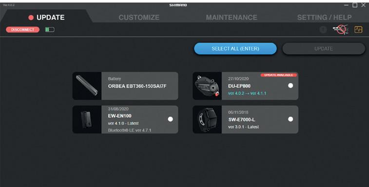
https://bike.shimano.com/en-EU/e-tube/project.html
er the greatest optimum asistance for each assist level.
BLUE PAPER KEMEN 2022 112 | ORBEA ORBEA | 113 TECHNICAL MANUAL EN
-
-
To connect the EP8 system to Etube Professional, a Shimano SM-PCE02 interface is needed.
It is also possible to connect and diagnose individual components of the EP8 system using the SM-PCE02. Consult the full Etube Professional manual here:
https://si.shimano.com/#/en/iUM/7J4WA/start_and_ stop_the_project/toc_concept_s2q_vmh_tlb
SHIMANO SM-PCE1 INTERFACE. The EP8 system can also be connected to Etube Professional using the Shimano SM-PCE1 interface.
To use the PCE1 it is necessary to use the Version 4 of Etube Professional. Etube V5 is not compatible with the PCE1.


You can download both versions of Etube Professional from the Shimano website.
CONNECTION OF SC-EM800 DISPLAY ASSEMBLIES
On models using the SC-EM800 display, it is possible to use one of the free display connectors to connect the SMPCE02 interface.
A SD300 cable must be connected to the display´s free connector and then use an EW-AD305 adapter to convert de SD300 cable to a SD50 cable standard, which is the SC-PCE02 PC-link cable standard.
Alternatively, an Y7EA03100 PC-link cable can be used to connect the display and the SM-PCE02 directly.
CONNECTION OF SC-E5003 DISPLAY ASSEMBLIES
On assemblies using the SC-E5003 display, that only has one SD300 port, it is necessary to use a Shimano EWJC304 juntion to gain a free port to connect the system to the SM-PCE02 interface.
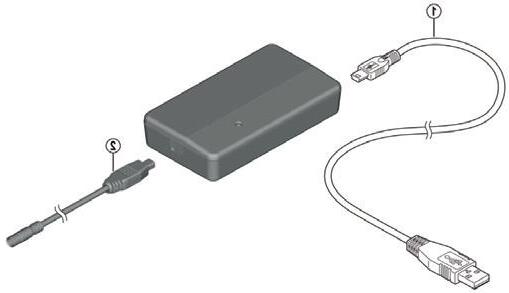
Disconnect the display cable and connect an EW-SD300 cable of any length from the display to the EW-JC304 juntion. Connect the motor cable to the juntion.
Connect another EW-SD300 cable of any length to a free port of the junction and use an EW-AD305 connector to convert this cable to the EW-SD50 cable standard. Connect the SM-PCE02 interface PC-Link cable to the SD50 connector port.
Alternatively, an Y7EA03100 PC-link cable can be used to connect the EW-JC304 junction and the SM-PCE02 directly.
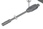
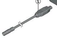
ORBEA RS BATTERY IN ETUBE PROFESSIONAL
The Orbea RS 540Wh internal battery is not diagnosticable using Etube Professional. If there is a problem in the electric system, use Etube Professional to rule out that the problem does not come from other of the Shimano system components.
Contact Shimano to provide them with a system report through a claim. If Shimano informs you that the problem comes from the internal battery, contact Orbea through a claim on Kide.
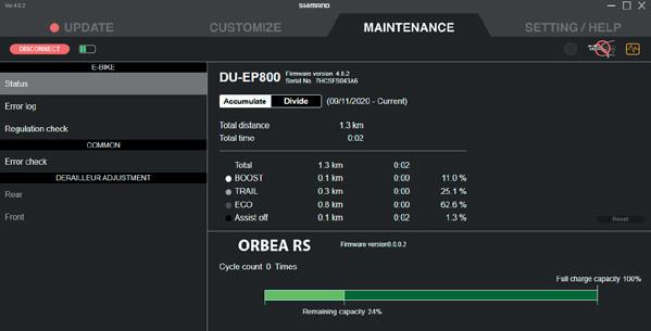
BLUE PAPER KEMEN 2022 114 | ORBEA ORBEA | 115
SC-EM800
Shimano SM-PCE02
EW-AD305
EW-SD300 EW-SD50
EW-JC304
SC-E5003
EW-AD305
EW-SD300
EW-SD300
TECHNICAL MANUAL EN
EW-SD50 Shimano SM-PCE02
EW-SD50 PC Link cable
MOTOR
SM-PCE02
EW-SD50 PC Link cable USB-Micro USB cable
20 REAR RACK AND MUDGUARDS KEMEN ASPHALT
KEMEN ASPHALT REAR RACK AND MUDGUARDS SPECIFICATIONS
REAR RACK
MATERIAL Aluminum
MAXIMUM LOAD 18Kg
CHILD SEAT COMPATIBLE No
ASSEMBLY To dropouts inner threads and rear mudguard blade
MIK COMPATIBLE No
ORTLEB QL3.1 SIDE MOUNT No
The Kemen Asphalt rear rack is only compatible with rear mudguard assemblies.
The rack attaches to the rear mudguard blade. Do not attach the Kemen Asphalt rear rack only using the threads on the inside of the frame´s rear dropouts.
Kemen is compatible with standard aftermarthread inserts on the inside of the seatstays.
MUDGUARDS
MANUFACTURER Curana
MODEL Apollo 65mm
MATERIAL Aluminum
29x2.2"
REAR RACK AND MUDGUARD ASSEMBLY.
KEMEN ASPHALT Consult the components and spare parts list at the end of this section.
TYRE MAXIMUM SIZE
Tyre maximum diameter: 741mm
Tyre maximum width: 55mm
ASSEMBLY See assembly section
BLUE PAPER KEMEN 2022 116 | ORBEA ORBEA | 117 4 5 N.m 4 5 N.m 4 5 N.m 4 5 N.m 2 2 N.m M5 M5 M5 M4 TECHNICAL MANUAL EN
FRONT MUDGUARD ASSEMBLY. KEMEN ASPHALT
FOX 34
AWL SUSPENSION FORK ASSEMBLIES
Consult the components and spare parts list at the end of this section.
A riveter should be used to install the fork attaching bracket to the mudguard blade. If you do not have access to a riveter or do not know how to use it, have a skilled mechanic install the bracket.
MARZOCCHI BOMBER Z2-E ASSEMBLIES
Consult the components and spare parts list at the end of this section.
BLUE PAPER KEMEN 2022 118 | ORBEA ORBEA | 119 TECHNICAL MANUAL EN
3 3 N.m 3 3 N.m 3 3 N.m 3 3 N.m 3 3 N.m
KEMEN SUV
KEMEN SUV REAR RACK AND MUDGUARDS SPECIFICATIONS
REAR RACK
MATERIAL Auminum
MAXIMUM LOAD
27Kg
CHILD SEAT COMPATIBLE Yes. Needs the seatstays bridge adapter. Included.
ASSEMBLY
Bottom: Thread inserts on the inside of the dropouts
Top: Rear mudguard blade. Seatstays bridge adapter
MIK COMPATIBLE Yes. MIK HD (Heavy Duty). See MIK section
ORTLEB QL3.1 SIDE MOUNT Yes. See Ortlieb QL3.1 section
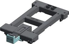
Kemen is compatible with standard aftermarthread inserts on the inside of the seatstays.
MUDGUARDS
MANUFACTURER Curana
MODEL Apollo 70mm
MATERIAL Auminum
29x2.35"
MIK & MIK HD
The Kemen SUV rear rack has a built-in MIK HD (heavyries and child seats. It is also compatible with non HD MIK accesories.
Consult all the relevant information about the MIK and MIK HD systems on the manufacturer´s website:
MIK PLATE (ATTACHED TO ACCESORY)
MIK website:
https://www.mik-click.com/mik-products/
MIK & MIK HD info:
https://www.mik-click.com/wp-content/uploads/2021/08/ MIK-2022_catalogue_version8.pdf
MIK HD PLATE (HEAVY DUTY) (ATTACHED TO ACCESORY)
TYRE MAXIMUM SIZE
Tyre maximum diameter: 750mm
Tyre maximum width: 62mm
MONTAJE See Assembly section
BLUE PAPER KEMEN 2022 120 | ORBEA ORBEA | 121 C TECHNICAL MANUAL EN
ORTLIEB QL 3.1
Besides standard side bags, the Kemen SUV rear rack can -
Rear more about the Ortlieb QL3.1 standard on the manufacturer´s website:
https://www.ortlieb.com/en_us/
REAR RACK AND MUDGUARD ASSEMBLY. KEMEN SUV
Consult the components and spare parts list at the end of this section.
STANDARD SIDE BAGS
ORTLIEB QL3.1 SIDE BAGS
BLUE PAPER KEMEN 2022 122 | ORBEA ORBEA | 123 4 5 N.m 4 5 N.m 4 5 N.m 2 1.5 N.m 5 5 N.m 4 5 N.m 4 5 N.m 5 4 N.m see hole distance M5 M5 M5 TECHNICAL MANUAL EN
SEATSTAYS BRIDGE MUDGUARD FIXING HOLE. DISTANCE
On Kemen SUV models, the hole for the bolt to attach the mudguard to the seatstays bridge adaptor is at a diferent position depending on the frame size.
If you purchase the Kemen SUV rear mudguard as a spare part from Orbea, the hole must be drilled in the correct position using a 4mm drill bit before installing the mudguard to the frame.
See the table in the image below and measure the distance to the hole center from the front end of the mudguard blade.
Drill the hole centered along the width of the mudguard blade.
mm
FRONT Hole distance (D)
FRONT MUDGUARD ASSEMBLY. KEMEN SUV FOX 34 AWL ASSEMBLIES
Consult the components and spare parts list at the end of this section.
A riveter should be used to install the fork attaching bracket to the mudguard blade. If you do not have access to a riveter or do not know how to use it, have a skilled mechanic install the bracket.
Kemen SUV size S > D = 295 mm
Kemen SUV size M > D = 320 mm
Kemen SUV size L > D = 344 mm
Kemen SUV size XL > D = 375 mm
REAR
BLUE PAPER KEMEN 2022 124 | ORBEA ORBEA | 125 TECHNICAL MANUAL EN
4
3 3 N.m 3 3 N.m 2 1.5 N.m 2 1.5 N.m 3 3 N.m
COMPONENTS AND SPARE PARTS
MARZOCCHI BOMBER Z2-E ASSEMBLIES
Consult the components and spare parts list at the end of this section.
REAR RACKS. ASPHALT & SUV
38REARRACKKEMENASPHALT
ARTNº:XB31COMPONENTSQTY.RELEVANTINFORMATION
Rear rack. Aluminum. Black. 18 Kg Max.1
2 2 2 2
39REARRACKKEMENSUV
· Maximum load capacity: 18Kg.
· Only with mudguard assemblies.
· Kemen Asphalt models.
ARTNº:XB41COMPONENTSQTY.RELEVANTINFORMATION
Rear rack. Aluminum. Black. 27 Kg Max. MIK HD interface. Ortlieb QL3.1 sides
· Maximum load capacity: 27Kg.
· Assembly to dedicated seatstay bridge adaptor.
· The length of the seatstays rods changes depending on the frame size:
Kemen SUV S-M: 275mm. Kemen SUV M-L: 215mm.
Bolt M6x15 ISO7380 rods2
Bolt M5x10 ISO7380. rods to seatstays bridge1
Washer M5 DIN125. rods to seatstays bridge1
MUDGUARDS KEMEN ASPHALT
40REARMUDGUARDKEMENASPHALT(COMPLETE)
ARTNº:XB32COMPONENTSQTY.RELEVANTINFORMATION
Mudguard blade Curana Apollo rear. Alloy. Black. 65mm1
Rear spoiler. Rubber. Apollo 65mm1
Rods. Apollo 65/340mm. Black1
Rod-frame bracket2
· Assembly only with Kemen Asphalt rear rack.
· Seatstays bridge adaptor not included.
Bolt M5x25 ISO7380 Seat tube1
Washer M5 DIN125 Seat tube1
Spacer 15mm Seat tube1
Rear light cable guide 850mm1
BLUE PAPER KEMEN 2022 126 | ORBEA ORBEA | 127 3 3 N.m 3 3 N.m 2 1.5 N.m TECHNICAL MANUAL EN
1
1
2 2 2
1
2
2
2 2 2
MUDGUARDS KEMEN ASPHALT
41HARDWAREKITREAR.MUDGUARDKEMENASPHALT
ARTNº:XB33COMPONENTSQTY.RELEVANTINFORMATION
Rear spoiler. Rubber. Apollo 65mm1
Rods. Apollo 65/340mm. Black1
Rod-frame bracket2
44FRONTMUDGUARD.KEMENASPHALT.MARZOCCHIBOMBERZ2-E.COMPLETE
ARTNº:XB35COMPONENTSQTY.RELEVANTINFORMATION
Mudguard blade Curana Apollo front. Alloy. Black. 65mm1
Front protector Apollo 65mm1
Rear spoiler rubber Apollo 65mm1
Fork bridge bracket1
Fork bridge bracket rear plate1
Bolt M5x25 ISO7380 Seat tube1
Washer M5 DIN125 Seat tube1
Spacer 15mm Seat tube1
Rear light cable guide 850mm1
42SEATSTAYSBRIDGEMUDGUARD.ADAPTOR65mmKEMENASPHALT
Seatstays bridge adaptor not included.
Bolt M5x40 ISO7380. Fork bridge bracket1
Fork bridge bracket spacer2
Rod Apollo 65/245mm. Black1
Rod-fork bracket2
Fork lowers clamp D402
Bolt M5x20 ISO7380 lowers clamps2
Nut M5 DIN985 lowers clamps2
45HARDWAREKITFRONT.MUDGUARD.KEMENASPHALT.FOX-MARZOCCHI
Marzocchi Bomber Z2-E assemblies.
ARTNº:XB23COMPONENTSQTY.RELEVANTINFORMATION
Seatstays bridge mudguard adaptor 65mm. Kemen Asphalt1
Bolt M4x12 DIN7991 Seatstays2
ARTNº:XB36COMPONENTSQTY.RELEVANTINFORMATION
Front protector Apollo 65mm1
Rear spoiler rubber Apollo 65mm1
Fork bridge bracket1
Bolt M6x15 ISO7380 fork bridge bracket1
Washer M6 DIN125 fork bridge bracket1
Rivet fork bridge bracket1
Rod Apollo 65/245mm. Black1
Rod-fork bracket2
Bolt M5x16 DIN7380 rods2
43FRONTMUDGUARD.KEMENASPHLATFOXAWL.COMPLETE
ARTNº:XB34COMPONENTSQTY.RELEVANTINFORMATION
Mudguard blade Curana Apollo front. Alloy. Black. 65mm1
Front protector Apollo 65mm1
Rear spoiler. Rubber Apollo 65mm1
Fork bridge bracket1
Bolt M6x15 ISO7380 fork bridge bracket1
Washer M6 DIN125 fork bridge bracket1
Rivet fork bridge bracket1
Rod Apollo 65/245mm. Black1
Rod-fork bracket2
Fox AWL rods plate2
Bolt M5x10 ISO7380 fork lowers2
Bolt M5x16 DIN7380 rods2
Nut M5 DIN985 Rods2
Fox AWL assemblies
A riveter should be used to install the fork attaching bracket to the mudguard blade.
Nut M5 DIN985 Rods2
46FOXAWLRODLOWERSPLATES.KITASPHALT-SUV
The top bracket on Marzocchi assemblies is not used on Fox AWL assemblies. Marzocchi fork bridge bracket not included. Marzocchi lowers clamps not included. Fox AWL rods lowers plates not included.
ARTNº:XB38COMPONENTSQTY.RELEVANTINFORMATION
Fox AWL rods plate2
Bolt M5x10 ISO7380 fork lowers2
Bolt M5x16 DIN7380 rods2
Nut M5 DIN985 Rods2
47LOWERSCLAMPSKIT.MARZOCCHIBOMBERZ2-E.ASPHALT-SUV
Compatible with Kemen Asphalt and SUV models with Fox AWL forks.
ARTNº:XB39COMPONENTSQTY.RELEVANTINFORMATION
Fork lowers clamp D402
Bolt M5x20 ISO7380 lowers clamps2
Nut M5 DIN985 lowers clamps2
Compatible with Kemen Asphalt and SUV models with Marzocchi Bomber Z2-E forks.
BLUE PAPER KEMEN 2022 128 | ORBEA ORBEA | 129 TECHNICAL MANUAL EN
2 2 2 2
MUDGUARDS KEMEN ASPHALT
48FORKBRIDGEM/GUARDBRACKET.MARZOCCHIBOMBERZ2-E.KEMENASPHALT-SUV
ARTNº:XB37COMPONENTSQTY.RELEVANTINFORMATION
Fork bridge bracket1
Fork bridge bracket rear plate1
Bolt M5x40 ISO7380. Fork bridge bracket1
Fork bridge bracket spacer2
MUDGUARDS KEMEN SUV
· The lower spacers are not used on Kemen SUV models.
51SEATSTAYSRACKADAPTORBRIDGE.KEMENSUV
ARTNº:XB44COMPONENTSQTY.RELEVANTINFORMATION
Seatstays rack adaptor bridge Kemen SUV1
Bolt M4x16 ISO7380 chainstays2
Washer M4 DIN125 chainstays2
52FRONTMUDGUARD.KEMENSUV.FOXAWLCOMPLETE
ARTNº:XB45COMPONENTSQTY.RELEVANTINFORMATION
Mudguard blade Curana Apollo front. Alloy. Black. 70mm1
49REARMUDGUARDKEMENSUV(COMPLETE)REARMUDGUARD
ARTNº:XB42COMPONENTSQTY.RELEVANTINFORMATION
Mudguard blade Curana Apollo rear. Alloy. Black. 70mm1
Rear spoiler. Rubber. Apollo 10mm1
Bolt M3x6 ISO7380 spoiler2
· For Kemen SUV rear rack assemblies.
· A hole for the seatstays bridge bolt needs to be drilled before assembly. Consult the hole position in the assembly section.
Front protector Apollo 70mm1
Bolt M3x6 ISO7380 protector1
Spoiler Orbea 70mm1
Bolt M3x6 ISO7380 spoiler2
Fork bridge bracket1
Bolt M6x15 ISO7380 fork bridge bracket1
Washer M6 DIN125 fork bridge bracket1
Rivet fork bridge bracket1
Rod Apollo 70/350mm. Black1
Rod-fork bracket2
Fox AWL rods plate2
Bolt M5x15 ISO7380 Seat tube1
Washer M5 DIN125 Seat tube1
Spacer 4.5mm Seat tube1
Rear light cable guide 850mm1
50HARDWAREKITREAR.MUDGUARDKEMENSUV
ARTNº:XB43COMPONENTSQTY.RELEVANTINFORMATION
Rear spoiler. Rubber. Apollo 10mm1
Bolt M3x6 ISO7380 spoiler2
Bolt M5x15 ISO7380 Seat tube1
Washer M5 DIN125 Seat tube1
Spacer 4.5mm Seat tube1
Rear light cable guide 850mm1
Fox AWL forks assemblies. A riveter should be used to install the fork attaching bracket to the mudguard blade.
Bolt M5x10 ISO7380 fork lowers2
Bolt M5x16 DIN7380 rods2
Nut M5 DIN985 Rods2
53FRONTMUDGUARD.KEMENSUV.MARZOCCHIBOMBERZ2-E.COMPLETE
ARTNº:XB46COMPONENTSQTY.RELEVANTINFORMATION
Mudguard blade Curana Apollo front. Alloy. Black. 70mm1
Front protector Apollo 70mm1
Bolt M3x6 ISO7380 protector1
Spoiler Orbea 70mm1
Bolt M3x6 ISO7380 spoiler2
Rod Apollo 70/350mm. Negro1
Rod-fork bracket2
Fork bridge bracket1
Fork bridge bracket rear plate1
Bolt M5x40 ISO7380. Fork bridge bracket1
Fork lowers clamp D402
Bolt M5x20 ISO7380 lowers clamps2
Nut M5 DIN985 lowers clamps2
BLUE PAPER KEMEN 2022 130 | ORBEA ORBEA | 131 TECHNICAL MANUAL EN
Marzocchi Bomber Z2-e assemblies.
1
1 1 1 1
1
1 1 1 1
MUDGUARDS KEMEN SUV
21 SUSPENSIONS
54MUDGUARDSHARDWAREKIT.FRONTKEMENSUV.FOX-MARZOCCHI
ARTNº:XB47COMPONENTSQTY.RELEVANTINFORMATION
Front protector Apollo 70mm1
Bolt M3x6 ISO7380 protector1
Spoiler Orbea 70mm1
Bolt M3x6 ISO7380 spoiler2
Fork bridge bracket1
Bolt M6x15 ISO7380 fork bridge bracket1
Washer M6 DIN125 fork bridge bracket1
Rivet fork bridge bracket1
Rod Apollo 70/350mm. Black1
Rod-fork bracket2
46FOXAWLRODLOWERSPLATES.KITASPHALT-SUV
The top bracket on Marzocchi assemblies is not used on Fox AWL assemblies.
-· Marzocchi fork bridge bracket not included.
Marzocchi lowers clamps not included.
Fox AWL rods lowers plates not included.
FOX AND MARZOCCHI FORKS SETTINGS
MANUFACTURER´S MANUALS
MARZOCCHI FORKS USER MANUAL:
ARTNº:XB38COMPONENTSQTY.RELEVANTINFORMATION
Fox AWL rods plate2
Bolt M5x10 ISO7380 fork lowers2
Bolt M5x16 DIN7380 rods2
Nut M5 DIN985 Rods2
47LOWERSCLAMPSKIT.MARZOCCHIBOMBERZ2-E.ASPHALT-SUV
Compatible with Kemen Asphalt and SUV models with Fox AWL forks.
ARTNº:XB39COMPONENTSQTY.RELEVANTINFORMATION
Fork lowers clamp D402
Bolt M5x20 ISO7380 lowers clamps2
Nut M5 DIN985 lowers clamps2
Compatible with Kemen Asphalt and SUV models with Marzocchi Bomber Z2-E forks.
48FORKBRIDGEM/GUARDBRACKET.MARZOCCHIBOMBERZ2-E.KEMENASPHALT-SUV
ARTNº:XB37COMPONENTSQTY.RELEVANTINFORMATION
Fork bridge bracket1
Fork bridge bracket rear plate1
Bolt M5x40 ISO7380. Fork bridge bracket1
Fork bridge bracket spacer2
The lower spacers are not used on Kemen SUV models.
FOX AND MARZOCCHI RAIL CARTRIDGE FORKS ADJUSTMENT GUIDE:
· FOX 34 FLOAT AWL RAIL, 29", 100mm QR15X110
· MARZOCCHI BOMBER Z2 29", 100mm, E-BIKE+, RAIL, QR15X110
https://www.ridefox.com/dl/bike/my22/605-00-242-AWL-Tuning-Guide-revB.pdf
FOX AND MARZOCCHI FORKS RECOMMENDED
SAG AND AIR PRESSURE GUIDE:
values may change depending of riding style and terrain conditions:
RECOMMENDED SAG
Fork´s total travel 15% SAG (Firm) 20% SAG (Soft)
Marzocchi Bomber Z2 RAIL 100mm 15mm20mm
Fox 34 Float AWL 100mm 15mm20mm
BLUE PAPER KEMEN 2022 132 | ORBEA ORBEA | 133 TECHNICAL MANUAL EN
REBOUND ADJUSTMENT SUGGESTION OF FOX
AND MARZOCCHI FORKS
RECOMMENDED AIR PRESSURE FOR SAG ADJUSTMENT
MARZOCCHI
Rider+gear weight (Kg)Rider+gear weight (Lb)Pressure (psi)
54-59120-13065
59-64130-14070
64-68140-15074
68-73150-16080
73-77160-17085
77-82170-18090
82-86180-19096
86-91190-200101
91-95200-210106
95-100210-220111
100-104220-230116
104-109230-240121
109-113240-250126
AIR VOLUME REDUCERS ON MARZOCCHI AND FOX FORKS
You can adjust the progressivity of your fork installing air volume reducers, which you can purchase from a Fox authorized dealer.
values may change depending of riding style and terrain conditions:
Turn the rebound dial clock-wise to the fully closed position. Then count "clicks" counter-clockwise as per the table below.
68-73150-1608
73-77160-1708
77-82170-1807
82-86180-1907
86-91190-2006
91-95200-2105
95-100210-2203
100-104220-2302
104-109230-2401
109-113240-2501
MARZOCCHI AND FOX RAIL FORKS SUGGESTED COMPRESSION SETTINGS
The RAIL cartridge has two compression preset positions: Open and Firm.
Fox recommends to start in the Open position and use the rest of the positions depending on the terrain and conditions.
The positions between the Open and Firm modes can be
BLUE PAPER KEMEN 2022 134 | ORBEA ORBEA | 135 TECHNICAL MANUAL EN
BOMBER Z2 RAIL & FOX 34 FLOAT AWL RAIL
Travel Installed from factory Maximum nº of reducers Marzocchi Bomber Z2 RAIL 100mm 66 Fox 34 Float AWL RAIL 100mm 66
Rider+gear weight (Kg)Rider+gear weight (Lb)Clicks
RECOMMENDED REBOUND SETTINGS MARZOCCHI BOMBER Z2 RAIL & FOX 34 FLOAT AWL RAIL
54-59120-13010 59-64130-1409 64-68140-1509
22 DECLARATION OF CONFORMITY
23 ADDITIONAL INFORMATION
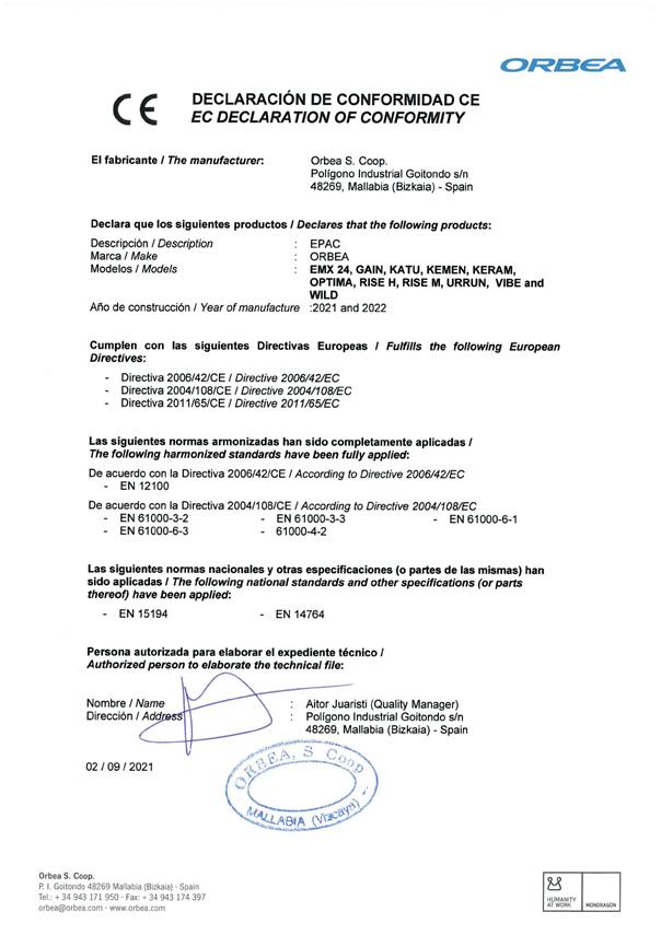
ORBEA participates actively on facebook and Twitter with our fantastic global community of riders. Looking to
the answers:
FACEBOOK
www.facebook.com/OrbeaBicycles
TWITTER
www.twitter.com/Orbea/
YOUTUBE

Visit our Orbea Channel on You Tube for a variety of helpful setup and tech videos: www.youtube.com/user/OrbeaBicycles
INSTAGRAM
www.instagram.com/orbeabicycles
ORBEA CONTENT
View and download photos, videos and documents. content.orbea.com/us-en/
BLOG ORBEA
www.orbea.com/gb-en/blog
YOUR ORBEA DEALER
Our dealers are experts and should be able to assist you with setting up and maintaining your Orbea bicycle. A com-plete listing of Orbea dealers and distributors can be located on our website:
www.orbea.com/us-en/dealers/?country=INT
CONTACT
Access Orbea´s contact details and form at:
www.orbea.com/es-es/contacto
USA:
www.orbea.com/us-en/contact/
BLUE PAPER KEMEN 2022 136 | ORBEA ORBEA | 137 TECHNICAL MANUAL EN
BLUE PAPER KEMEN 2022
EN 01 | ES 70 | FR 139 | IT 208 | DE 277 MANUAL TÉCNICO
BLUE PAPER KEMEN 2022 2 | ORBEA ORBEA | 3 MANUAL TÉCNICO ES 01 LEYENDA DE SÍMBOLOS 7 02 GARANTÍA ORBEA 8 Garantía legal 8 Garantía de por vida Orbea 8 Registra tu bicicleta 8 Garantía de componentes del sistema de asistencia eléctrica 9 Proceso de reclamaciones de garantía 10 03 MANTENIMIENTO 11 Mantén limpia tu bicicleta 11 Mantén lubricada tu transmisión 11 Inspecciona tu bicicleta antes de cada salida 11 Periodos de mantenimiento de los componentes 12 Actualizaciones del sistema eléctrico 14 Recambios 14 Después de un golpe o impacto 15 04 ADVERTENCIAS DE USO DE KEMEN 16 Tamaño máximo de cubierta 16 Inserción mínima de la tija de sillín 16 Longitud máxima de horquilla 16 Máximo número de separadores de dirección 16 Posición de la potencia en el tubo de la horquilla 17 Uso previsto 17 05 ADVERTENCIAS DE USO DE LOS COMPONENTES DEL SISTEMA DE ASISTENCIA ELÉCTRICA 18 Cuidados y normas de uso de los componentes eléctricos y las baterías 18 Autonomía 19 Transporte de baterías de bicicletas eléctricas 20 Transporte de bicicletas eléctricas 20 06 USO DE KEMEN 21 Encendido/apagado de Kemen 21 Visualización del nivel de carga de la batería 21 Carga de las baterías 22 Cambio del nivel de asistencia 26 Encender/apagar las luces 27 Errores/advertencias en el sistema 29 ÍNDICE
BLUE PAPER KEMEN 2022 4 | ORBEA ORBEA | 5 MANUAL TÉCNICO ES 07 SHIMANO ETUBE PROJECT CYCLIST 30 Personalización del sistema de asistencia eléctrica 30 Visualización de errores en el sistema 32 08 ORBEA RS TOOLBOX. CAMPO DE DATOS PARA DISPOSITIVOS GARMIN 33 Instalación y desbloqueo de Orbea RS Toolbox en dispositivos Garmin 33 Visualización de Orbea RS Toolbox tu dispositivo 37 Uso de Orbea RS Toolbox 40 Registro de datos de Kemen en actividades de Garmin Connect 43 09 GEOMETRÍA Y ERGONOMÍA 44 Altura máxima y mínima de sillín con tijas telescópicas 46 10 ESPECIFICACIONES TÉCNICAS 48 COMPONENTES. DESPIECE, MONTAJE, USO Y REPUESTOS 55 11 DIRECCIÓN 55 Dimensiones de la pipa de dirección 55 Despiece y montaje de la dirección 56 12 EJE TRASERO Y PATA DE CAMBIO 57 Compatibilidad de trailers/carros para niños 57 13 PROTECTORES 58 14 PLATO 59 15 OTRO DESPIECE DE CUADRO 60 16 PATA DE CABRA 61 17 POTENCIA 62 Potencia Orbea Urban ICR 35 62 Despiece y montaje de potencia Orbea Urban ICR 35 63 18 CABLEADO DE ELEMENTOS MECÁNICOS 64 19 SISTEMA ELÉCTRICO 65 Esquema de conexión de componentes 65 Cableado en cuadro de componentes Shimano 68 Instalación de display SC-EM800 en montajes con display SC-E5003 70 Conectividad Bluetooth y ANT Private 70 Cableado en cuadro de componentes Orbea RS 72 Componentes del sistema eléctrico Shimano y Orbea RS 76 Compatibilidad de discos de freno 77 Manillar 79 Luces 81 Montaje de luz delantera en potencia 86 Montaje de luz de día integrada en tapa de dirección 86 Montaje de luz trasera en parrilla o guardabarros 87 Cableado y conexión de componentes 88 Componentes del sistema de luces 91 Fijación del motor EP8 92 Batería interna RS 540Wh 93 Desmontaje de la batería interna RS. Información para distribuidores Orbea 95 Batería externa Orbea Range Extender RS 252Wh 2022 99 Aviso importante de uso de la batería Range Extender RS en Kemen 99 Montaje del Range Extender 101 Conexión 102 Funcionamiento 103 Nivel de carga 104 Estado de salud 104 Códigos de error 105 Repuestos 106 Smart Charger RS 2A-4A 107 Información relevante de las baterías de Ion-Litio Orbea RS 110 Conexión del sistema a Etube Project Professional. Información para distribuidores 113 20 PARRILLA Y GUARDABARROS 116 Montaje de parrilla y guardabarros trasero 117 Montaje de guardabarros delantero 118 KEMEN SUV 120 Montaje de parrilla y guardabarros trasero 123 Montaje de guardabarros delantero 125 Componentes y repuestos 127 21 SUSPENSIONES 133 Ajustes de las horquillas Marzocchi y Fox 133 22 DECLARACIÓN DE CONFORMIDAD 136 23 INFORMACIÓN ADICIONAL 137
Este manual técnico contiene información importante de tu bicicleta sobre su uso, mantenimiento y repuestos. Leelo con atención.
Este documento es un suplemento del Manual General de Usuario de bicicletas y componentes Orbea, que describe de forma más detallada el uso apropiado y ajuste de los componentes generales de las bicicletas para una circulación y operación seguras. Puedes ver y descargar el Manual de Usuario, así como el resto de manuales técnicos de productos Orbea, de nuestra página web: www.orbea.com/es-es/soporte/manuales
Puedes consultar la información relevante de uso, mantenimiento y características de los componentes de otros fabricantes montados en nuestras bicicletas, como ruedas, manillares, sistemas de asistencia al pedaleo, horquillas de suspensión, etc, en la web del fabricante en cuestión o a través de su distribuidor en tu país.
01 LEYENDA DE SÍMBOLOS
A lo largo de este manual técnico, se utilizan varios símbolos que detallan instrucciones y advertencias de uso, mantenimiento y montaje. Presta atención a estos símbolos para evitar situaciones peligrosas y asegurar el uso y montaje correcto de todos los componentes.
puede que el símbolo aparezca acompañado únicamente de la instrucción relevante para el componente en que describe. Lee la siguiente información con
INSTRUCCIONES DE SEGURIDADHERRAMIENTAS
PELIGRO: Situación peligrosa que, si no se evita, provocará lesiones graves o incluso la muerte.
ADVERTENCIA: Situación peligrosa que, si no se evita, puede causar lesiones graves o incluso la muerte.
ATENCIÓN: Situación peligrosa que, de no evitarse, podría provocar lesiones leves o moderadas.
Situación no relacionada con lesiones físicas. Información relevante.
RIESGO DESCARGA ELÉCTRICA: Situación peligrosa que, si no se evita, puede causar lesiones graves por descarga eléctrica, o incluso la muerte.
RIESGO CORTOCIRCUITO: No observar las indicaciones puede producir cortocircuitos en los componentes eléctricos, pudiendo ser causa de daños en los componentes e incendios.
Los símbolos PELIGRO y ADVERTENCIA siempre implican un riesgo de accidente si no se toman medidas para evitar la situación que describen. Un accidente circulando con una bicicleta siempre puede conllevar riesgo de lesiones graves o incluso de muerte. En este manual no siempre se repetirá el riesgo de muerte cuando aparezcan estos símbolos, ya que el riesgo se detalla en este punto.
El número de llave a usar se indica en el interior del símbolo
PARES DE APRIETE: El par de apriete correspondiente (en newton/metro) aparece indicado debajo del símbolo de la herramienta a usar para el elemento que describe.
TIPO DECOMPUESTO
ACEITE: Lubricación ligera de elementos como cadenas y cables.
GRASA: Grasa de montaje de calidad para
PASTA DE CARBONO: Compuesto de montaje para elementos de carbono para aumentar fricción entre elementos.
LOCTITE SERIE 600: Fijador de piezas cilíndricas.
LOCTITE SERIE 200: Fijador o trabarroscas. Resistencia media.
LOCTITE SERIE 400: Adhesivo instantáneo.
BLUE PAPER KEMEN 2022 6 | ORBEA ORBEA | 7 MANUAL TÉCNICO ES
LLAVE PLANA
LLAVE ALLEN
LLAVE TORX
DESTORNILLADOR TIPO PHILIPS
AVISO
GREASE FIBER CARBON GRIP
6 6
Nuestro esfuerzo continuo y diario por ofrecer la máxima calidad en nuestras bicicletas nos permite brindar la siguiente garantía y condiciones de cobertura:
GARANTÍA LEGAL
Orbea ofrece al propietario original de la bicicleta Orbea, horquilla rígida o el componente OC o propio una garantía legal de 3 años desde el momento de la compra del artículo, o el periodo estipulado como garantía legal en el país de compra.
Esta garantía cubre todos los productos de Orbea frente a defectos de fabricación y/o falta de conformidad y garantiza la reparación o sustitución del producto defectuoso sin coste adicional para el cliente afectado. Igualmente, esta garantía cubre también los defectos de pintura, barniz y corrosión de todos los cuadros y horquillas rígidas quecado en el párrafo anterior de esta garantía.
Esta garantía no cubre en ningún caso los daños derivados de un uso inadecuado, caídas o accidentes o falta de mantenimiento, así como el deterioro habitual de las piezas de desgaste tales como, a título meramente informativo y no limitativo: retenes, rodamientos, cinta de manillar, radios, cubiertas, sillines, etc.
Para conocer la descripción completa de las condiciones de la cobertura y la garantía legal, visita:
www.orbea.com/es-es/garantia
GARANTÍA DE POR VIDA ORBEA
Como complemento a la garantía legal, Orbea ofrece al comprador original de la bicicleta, siempre que haya registrado su producto en el sitio web de Orbea en los 30 días siguientes a la compra, la garantía comercial de por vida Orbea, que cubre los cuadros y horquillas rígidas que montamos en nuestras bicicletas sin límite temporal frente a defectos de fabricación y conformidad de los materiales.
Esta garantía amplía el periodo original de cobertura de los defectos de pintura, barniz y corrosión de los cuadros de garantía legal.
La garantía comercial de por vida Orbea sólo cubre cuadros y horquillas rígidas, no componentes OC u otros componentes propios Orbea.
Para conocer la descripción completa de las condiciones de la garantía de por vida, visita:
www.orbea.com/es-es/garantia/#garantia-deporvida-orbea
REGISTRA TU BICICLETA
vida Orbea, debes registrar tu bicicleta en los 30 días siguientes a su compra en:
www.orbea.com/es-es/acceso-registro?from=register-plate/
GARANTÍA DE COMPONENTES DEL SISTEMA DE ASISTENCIA ELÉCTRICA
COMPONENTES SHIMANO STEPS
Los componentes del sistema eléctrico Shimano STEPS (motor, displays, sensor de velocidad, pulsador de cambio de nivel de asistencia, centralitas y cableado Di2-STEPS) están cubiertos por una garantía legal de 2 años desde el momento de la compra del artículo o la bicicleta, o el periodo estipulado como garantía legal en el país de compra.
La tramitación de cualquier solicitud de garantía debe realizarse con Shimano a través de un distribuidor autorizado de la marca.
COMPONENTES RS EXCLUSIVOS ORBEA
Los componentes del sistema eléctrico exclusivos de Orbea (batería interna, Range Extender, cable harness de conexión a la batería, motor y puerto de carga, interruptor de encendido del sistema o componentes de alumbrado propios) están cubiertos por una garantía legal de 3 años desde el momento de la compra del artículo o la bicicleta, o el periodo estipulado como garantía legal en el país de compra.
La tramitación de cualquier solicitud de garantía debe realizarse con Orbea a través de uno de nuestros distribuidores autorizados.
Estas garantías cubren todos los productos de Shimano y Orbea frente a defectos de fabricación y/o falta de conformidad y garantiza la reparación o sustitución del producto defectuoso sin coste adicional para el cliente afectado.
Esta garantía no cubre en ningún caso los daños derivados de un uso inadecuado, caídas o accidentes, instalación incorrecta o falta de mantenimiento o no observación de las indicaciones de uso, almacenamiento, carga, etc. de este manual.
La pérdida de capacidad de las baterías Orbea (batería interna y Range Extender) debido al envejecimiento natural de las mismas por uso, carga y almacenamiento no está contemplado dentro de las condiciones de garantía.
BLUE PAPER KEMEN 2022 8 | ORBEA ORBEA | 9 MANUAL TÉCNICO ES
02
GARANTÍA ORBEA
01. REGISTRA TU CUENTA
02. REGISTRA TU MATRÍCULA
03. DONDE ENCONTRAR TU MATRÍCULA
PROCESO DE RECLAMACIONES DE GARANTÍA
Todas las reclamaciones de garantía deben ser procesadas a través de un distribuidor autorizado Orbea, quien realizará el diagnóstico inicial y remitirá a Orbea, Shimano o el fabricante del componente de la reclamación toda la documentación necesaria para realizar un diagnóstico completo de la reclamación en cuestión. El distribuidor informará al propietario del estado del proceso y de la decisión sobre la reclamación de garantía por Orbea, Shimano o el fabricante del componente en cuestión.
RECLAMACIONES DE GARANTÍA Y REPARACIÓN DE COMPONENTES DEL SISTEMA DE ASISTENCIA ELÉCTRICA
SHIMANO: La tramitación de reclamaciones de garantía o reparación de los siguientes componentes del sistema eléctrico serán procesadas a través de Shimano:
· Motor Shimano EP8.
· Displays SC-EN800, SC-E7000 y SC-E5003.
· Sensor de velocidad.
· Manetas de cambio de nivel de asistencia SW-EM800L y SW-E7000-L.
ORBEA: La tramitación de reclamaciones de garantía o reparación de los siguientes componentes del sistema eléctrico serán procesadas a través de Orbea:
· Batería externa Range Extender.
· Batería interna Orbea RS 540Wh
· Cable harness de conexión a la batería interna, al motor y al puerto de carga.
· Interruptor de encendido del sistema eléctrico.
· Luz integrada en dirección.
· Cables de luces.
Te recomendamos que siempre acudas al distribuidor donde compraste tu bicicleta para tramitar una reclamación de garantía, o a aquel que elegiste durante el proceso de compra de una bicicleta que te fue entregada directamente en tu domicilio. En caso de no poder acudir al distribuidor original, puedes comprobar la lista de distribuidores autorizados en nuestra web o contactar con Orbea para que te indiquemos el distribuidor al que acudir.
www.orbea.com/es-es/distribuidores/?country
www.orbea.com/es-es/contacto/
03 MANTENIMIENTO
Los productos Orbea son cuidadosamente diseñados paradros y horquillas de carbono y aluminio son extremadamente resistentes a la corrosión.
Sin embargo, tu bicicleta necesita un mantenimiento periódico de sus componentes para asegurar su correcto funcionamiento, seguridad y longevidad.
MANTÉN LIMPIA TU BICICLETA
Limpia tu bicicleta con agua y jabón suave de manera regular para mantenerla como el primer día y poder comprobar el estado del cuadro y sus componentes. No utilices agua a presión, ya que podría dañar componentes como los rodamientos o los tubos del cuadro.
Los desengrasantes a base de cítricos son biodegradablesponentes de la transmisión y la cadena.
inspección visual de los componentes y ocultar daños que podrían potencialmente producir averías o accidentes.
La suciedad acumulada provoca el desgaste prematuro de los componentes, y puede incluso dañar el cuadro de la bicicleta en zonas como alojamientos de rodamientos y partes móviles. Los daños por falta de limpieza y mantenimiento no están contemplados por las coberturas de garantía.
MANTÉN LUBRICADA TU TRANSMISIÓN
Una vez hayas limpiado tu bicicleta, lubrica la transmisión, concretamente la cadena. Utiliza la mínima cantidad necesaria para lubricar los eslabones, limpiando cualquier exceso para evitar que éste atraiga la suciedad y provoque que la transmisión no funcione correctamente y el desgaste prematuro de los componentes.
Evita el uso de lubricantes en aerosol para de frenado. Siempre comprueba los frenos tras lubricar la transmisión.
INSPECCIONA TU BICICLETA ANTES DE CADA SALIDA
Realiza una inspección rápida antes de cada salida para de funcionamiento. Podrías encontrar pequeños problemas que se pueden convertir en incidencias importantes durante el trayecto.
CUADRO: Inspecciona el cuadro y la horquilla en busca de daños o grietas. No debe presentar ruidos extraños. Ante cualquier daño en el cuadro, evita el uso de la bicicleta y contacta con tu distribuidor autorizado para una revisión.
CADENA: Debe estar limpia y lubricada, y la transmisión no debe producir ruidos fuera de lo normal.
FRENOS: componentes.
CUBIERTAS: Comprueba el desgaste de las cubiertas y busca cortes en la banda de rodadura o en los laterales, si encuentras daños, reemplaza la cubierta. Comprueba que la presión de los neumáticos es la adecuada.
RUEDAS: Comprueba que las ruedas giran de manera suave y que no tiene desviaciones laterales. Tira ligeramente de la rueda hacia los lados para comprobar que no hay cierres rápidos están apretados de manera segura y al par de apriete correcto.
DIRECCIÓN: Acciona el freno delantero y mueve la parte frontal de la bicicleta hacia adelante y hacia atrás ejerciendo presión en el manillar con la rueda delantera en el suelo. Comprueba que no haya ruidos extraños o movimiento de la dirección, que podría indicar que los rodamientos están gastados o la dirección no está apretada correctamente. Con la dirección ajustada correctamente, comprueba que la dirección gira de manera suave.
PUNTOS DE GIRO DEL BASCULANTE: En bicicletas de doble suspensión, comprueba que todos los puntos de giro del basculante giren de manera suave y no presenten juego en los rodamientos.
BLUE PAPER KEMEN 2022 10 | ORBEA ORBEA | 11 MANUAL TÉCNICO ES
AVISO
Tira del basculante hacia un lado y otro de la bicicleta y presta atención a ruidos o juego en los puntos de giro. Si el basculante no funciona suavemente o presenta juego, podría ser un indicador de que los pares de apriete no son correctos o que los rodamientos están desgastados o dañados.
RODAMIENTOS: Los rodamientos (eje de pedalier, puntos de giro del basculante, dirección, ruedas, etc) son elementos de desgaste que deben ser comprobados periódicamente para garantizar su correcto funcionamiento. Rodamientos en mal estado pueden dañar los componentes en los que están instalados. Condiciones meteorológicas adversas aceleran el desgaste de los rodamientos. Rodamientos que presentan juego o que no giran suavemente deben ser reemplazados inmediatamente. Ante cualquier duda, consulta con tu distribuidor autorizado.
Daños en componentes como el cuadro, ruedas de tu bicicleta, etc, derivados de falta de mantenimiento y sustitución de los rodamientos no están cubiertos por las condiciones de la garantía.
SISTEMA ELÉCTRICO: Enciende la bicicleta y comprueba que el sistema eléctrico funciona correctamente. Comprueba que haya asistencia eléctrica y que todos los componentes funcionan (motor, display, cambio de asistencia, sensor de velocidad y luces).
Si no hay asistencia eléctrica, comprueba todas las conexiones entre los componentes y el estado de los mismos y los cables (cables o componentes que muestren daños deben ser reemplazados).
Comprueba si hay errores en el sistema eléctrico. Los displays de Shimano SC-EN800 ó SC-E5003 mostrarán el código de error si lo hubiese.
En montajes con display SC-EN800, puedes conectar el sistema eléctrico mediante Bluetooth a la aplicación para móviles Shimano Etube Project Cyclist para saber más sobre el código de error o advertencia y acceder al método de resolución de los mismos. Si el sistema eléctrico sigue sin funcionar tras aplicar el método descrito, o si no hay un método a aplicar por el usuario, lleva tu bicicleta a un distribuidor autorizado para su diagnóstico y reparación.
El display Shimano SC-E5003 no dispone de conectividad Bluetooth, por lo que no podrás conectar la bicicleta a la aplicación Etube Project Cyclist. Para conocer el método de resolución del error o advertencia, consulta el código de error en el manual del sistema Shimano STEPS o lleva tu bicicleta a un distribuidor autorizado Shimano para realizar un diagnóstico del sistema eléctrico o reemplaza el display original por un display Shimano SC-EM800.
Consulta el listado de códigos de error y advertencias del sistema Shimano STEPS y su método de resolución en el siguiente link:
https://si.shimano.com/#/en/iER/STP0A
No seguir las indicaciones descritas en estos puntos y utilizar una bicicleta que presenta los síntomas descritos puede provocar accidentes y lesiones graves.
PARES DE APRIETE. Siempre comprueba los pares de apriete e instala los componentes descritos en este manual siguiendo las indicaciones del par de apriete. Sigue las indicaciones de pares de apriete para componentes de otros fabricantes instalados en tu bicicleta Orbea. No observar estas indicaciones puede conducir a la falla de los componentes, accidentes e incluso la muerte.
PERIODOS DE MANTENIMIENTO DE LOS COMPONENTES
Los periodos de mantenimiento de los componentes indicados a continuación son orientativos, y dependen en gran medida de factores como las condiciones meteorológicas de uso de la bicicleta (condiciones adversas reducen considerablemente la vida de los componentes y los tiempos de mantenimiento), limpieza de la bicicleta y sus componentes (componentes con suciedad acumulada se desgastan más rápidamente) y uso (un uso más exigente de la bicicleta requerirá periodos de mantenimiento más cortos).
Para componentes de otras marcas montados en bicicletas Orbea, puedes comprobar los periodos de mantenimiento recomendados u obligatorios en la web del fabricante o contactando con el distribuidor de la marca en tu país.
Daños en los componentes derivados del no cumplimiento de los periodos de mantenimiento podría ocasionar daños que no estarían cubiertos por las condiciones de garantía de Orbea o del fabricante del componente.
El no cumplimiento de los periodos de mantenimiento puede producir daños en los componentes que deriven en averías y accidentes.
DIRECCIÓN:
· Inspección del funcionamiento antes de cada uso de la bicicleta.
· Desmontaje e inspección manual de los rodamientos cada 6 meses de uso.
PEDALIER:
· Inspección del funcionamiento antes de cada uso de la bicicleta.
· Desmontaje e inspección manual de los rodamientos cada 6 meses de uso.
TRANSMISIÓN:
· Inspección del funcionamiento antes de cada uso de la bicicleta.
· Inspección regular del desgaste de la cadena cada 500 km. Una cadena gastada más allá de las recomendaciones del fabricante debe ser sustituida para evitar daños al resto de componentes de la transmisión. No observar las indicaciones de desgaste del fabricante podría requerir la sustitución del resto de elementos de la transmisión.
RUEDAS:
· Inspección del funcionamiento antes de cada uso de la bicicleta.
· Desmontaje y revisión manual de los rodamientos y todos los componentes cada 6 meses.
AMORTIGUADORES Y HORQUILLAS DE SUSPENSIÓN:
· Inspección del funcionamiento antes de cada uso de la bicicleta.
· Revisión y mantenimiento completo cada 125 horas o anual (lo que antes ocurra) por el distribuidor autorizado por el fabricante.
TIJAS TELESCÓPICAS:
· Inspección del funcionamiento antes de cada uso de la bicicleta.
· Revisión y mantenimiento completo cada 125 horas o anual (lo que antes ocurra) por el distribuidor autorizado por el fabricante
PUNTOS DE GIRO EN CUADROS DE DOBLE SUSPENSIÓN:
· Inspección del funcionamiento antes de cada uso de la bicicleta.
· Desmontaje del cuadro e inspección manual de todos los rodamientos cada 125 horas de uso o anual (lo que antes ocurra). Estos tiempos podrían acortarse dependiendo de las condiciones de uso de la bicicleta. Un uso exigente de la bicicleta o en condiciones meteorológicas adversas o con barro requiere el desmontaje e inspección del cuadro cada 75 horas de uso o cada 6 meses (lo que antes ocurra). Si un rodamiento no gira suavemente o tiene juego, debe ser reemplazado inmediatamente.
CABLES Y FUNDAS DE CAMBIO:
· Inspección del funcionamiento antes de cada uso de la bicicleta.
· Sustitución de cables de cambio cada 6 meses o un año, dependiendo de las condiciones de uso de la bicicleta.
FRENOS:
· Inspección del funcionamiento y del desgaste de las pastillas o zapatas de freno antes de cada uso de la bicicleta.
· Comprobación del desgaste de los discos de freno y los cables o líneas hidráulicas cada 6 meses o un año, dependiendo de las condiciones de uso de la bicicleta. Purgado de las líneas hidráulicas cada año.
COMPONENTES DE DEL SISTEMA DE ASISTENCIA ELÉCTRICA:
Comprueba regularmente las conexiones y cables de los componentes del sistema de asistencia eléctrica en tu bi-
BLUE PAPER KEMEN 2022 12 | ORBEA ORBEA | 13 MANUAL TÉCNICO ES
AVISO AVISO
AVISO AVISO AVISO
cicleta. Las conexiones deben estar limpias y no presentar objetos extraños. Los cables deben estar en buen estado y no presentar cortes o dobleces que puedan causar cortocircuitos y falta de asistencia eléctrica.
El exterior de los componentes como mandos remotos y baterías no deben mostrar daños que permitan el ingreso de agua y otros elementos. Ante cualquier daño de los componentes eléctricos, dirígete a tu distribuidor Orbea para su diagnóstico y/o sustitución.
Consulta la sección de Advertencias de Uso del sistema de asistencia eléctrica de este manual para conocer el cuidado correcto de sus componentes.
ACTUALIZACIONES DEL SISTEMA ELÉCTRICO:
Los sistemas de asistencia eléctrica para ebikes pueden ser susceptibles de mejoras o actualizaciones que mejoren el funcionamiento del sistema.
Algunas actualizaciones del sistema Shimano STEPS son realizadas mediante Bluetooth® al conectar tu bicicleta a la aplicación para smartphones Shimano Etube Project Cyclist.
Al realizar una actualización del sistema a través de Bluetooth® usando la aplicación para móviles Etube Project Cyclist, siempre es recomendable desactivar la conexión a redes móviles y WiFi para evitar que una llamada o mensaje entrante pueda interrumpir la actualización. En caso de que la actualización sea interrumpida y esto provoque algún mal funcionamiento de la bicicleta, lleva tu bicicleta a un distribuidor autorizado Orbea para realizar la actualización usando la interfaz para distribuidores SM-PCE02 de Shimano.
Consulta aquí el manual de la aplicación Shimano Etube Project Cyclist:
https://si.shimano.com/#/es/iUM/7J4MA/
Otras actualizaciones deben ser llevadas a cabo por un distribuidor autorizado. Recuerda a tu distribuidor comprobar si existen actualizaciones disponibles para tu bicicleta cuando lleves ésta para mantenimiento o reparaciones.
El display Shimano SC-E5003 no dispone de conectividad Bluetooth, por lo que no podrás conectar la bicicleta a la aplicación Etube Project Cyclist para realizar actualizaciones del sistema eléctrico. Acude a tu distribuidor autorizado para que compruebe si hay actualizaciones disponibles conectando la bicicleta a la herramienta Etube Project Professional mediante la interfaz SM-PCE02 de Shimano o reemplaza el display original por un display Shimano SC-EM800.
Algunas de estas comprobaciones y mantenimientos están más allá del conocimiento mecánico de la mayoría de usuarios de bicicle-
mantenimientos necesarios, acude siempre a un distribuidor Orbea para el mantenimiento de tu bicicleta y sus componentes. No realizar los mantenimientos de manera adecuada puede resultar en averías y accidentes de graves consecuencias.
Mantenimientos realizados de manera incorrecta pueden producir daños en los componentes que no están cubiertos por las condiciones de la garantía.
RECAMBIOS
Utiliza siempre recambios originales Orbea, Shimano o del fabricante del componente en cuestión.
El uso de repuestos no originales puede producir daños que deriven en averías y accidentes de graves consecuencias.
La instalación de alguno de los repuestos en este manual técnico está más allá del conocimiento mecánico de la mayoría de -
cado para instalar estos repuestos, acude siempre a un distribuidor Orbea para el mantenimiento de tu bicicleta y sus componentes. No instalar los repuestos de manera adecuada puede resultar en averías, accidentes y lesiones graves.
La instalación de repuestos no originales pueden producir daños en tu bicicleta que no están cubiertos por las condiciones de garantía.
DESPUÉS DE UN GOLPE O IMPACTO
Caerse de la bicicleta es inherente al ciclismo. Si sufres un accidente con tu bicicleta Orbea, asegúrate de que te encuentras bien y pide atención médica si es necesario. Si no has sufrido lesiones, deberás comprobar el estado de tu bicicleta antes de continuar.
INSPECCIONA EL CUADRO Y LOS COMPONENTES DE LA BICICLETA PARA COMPROBAR SI HAN SUFRIDO DAÑOS.
Si detectas algún problema, no sigas circulando con la bicicleta.
PUNTOS A REVISAR
cualquiera de estos componentes se ha roto o doblado. Si detectas alguna rotura o grieta, debes dejar de utilizar la bicicleta inmediatamente. En cuadros de carbono, busca grietas o zonas blandas en el carbono, si detectas alguno de estos síntomas, debes dejar de utilizar la bicicleta inmediatamente.
Los materiales utilizados en cuadros y horquillas de carbono son rígidos y fuertes, pero
cientemente fuerte en este material podría producir daños que, aunque no visibles a primera vista, podrían producir un fallo de los materiales en el futuro. Ante cualquier duda de las consecuencias de una caída o accidente, contacta con tu distribuidor Orbea para un correcto diagnóstico de los materiales.
Comprueba la transmisión y las ruedas para asegurarte de que los componentes funcionen correctamente. Si descubres algún daño en los componentes, deja de utilizar la bicicleta inmediatamente.
Incluso en el caso de que no observes daño alguno, presta la máxima atención al sonido de tu bicicleta cuando vuelvas a montar en ella. Las roturas y otros problemas algún ruido poco habitual, deja de usar la bicicleta inmediatamente y contacta con tu distribuidor Orbea para un correcto diagnóstico de la misma.
LLEVA TU BICICLETA ORBEA A UN DISTRIBUIDOR AUTORIZADO PARA SOMETERLA A UNA INSPECCIÓN PROFESIONAL
Algunas de las consecuencias de una caída o accidente sólo pueden detectarse desmontando la bicicleta completamente para comprobar la presencia de roturas u otras señales de deterioro.
Un golpe o impacto pueden ocasionar graves desperfectos en tu bicicleta y en los componentes de ésta., provocando que fallen o se desgasten prematuramente. Los fallos pueden producirse de manera repentina y sin previo aviso, causando la pérdida de control de la bicicleta, lesiones graves o incluso la muerte.
BLUE PAPER KEMEN 2022 14 | ORBEA ORBEA | 15 MANUAL TÉCNICO ES
-
AVISO AVISO AVISO AVISO AVISO
DE USO DE KEMEN
TAMAÑO MÁXIMO DE CUBIERTA
cubierta que puede ser montado en el cuadro, siempre respeta estas indicaciones al instalar una cubierta en tu bicicleta.
Sin embargo, las medidas reales de circunferencia y ancho de cubierta pueden cambiar de un fabricante a otro. Al instalar una cubierta diferente a la que montaba tu bicicleta Orbea originalmente, comprueba que la distancia entre la parte superior y los laterales de la cubierta es de al menos 6 mm entre la misma y cualquier parte del cuadro.
AVISO
Daños en el cuadro o los componentes debidos al uso de una cubierta que no observe estas medidas no están cubiertas por las condiciones de la garantía.
INSERCIÓN MÍNIMA DE LA TIJA DE SILLÍN
Siempre respeta las indicaciones de inserción mínima de la tija a utilizar o del cuadro en bicicletas de carretera con tijas exclusivas Orbea. No respetar estas indicaciones puede producir esfuerzos en los materiales más allá de las condiciones para las que fueron diseñados y producir roturas no cubiertas por las condiciones de garantía, así como accidentes que pueden producir lesiones graves.
LONGITUD MÁXIMA DE HORQUILLA (AXLE-TO-CROWN)
Respeta siempre la longitud máxima de horquilla listada entre el eje de la horquilla y la parte inferior de la pipa de dirección (axle-to-crown).
nicas el recorrido máximo de horquillas de suspensión compatible con el cuadro.
No respetar esta medida e instalar horquillas con una longitud mayor que la máxima allá de las características para las que fue diseñado, pudiendo producir fallos en el material que podrían ser causa de accidentes y lesiones graves.
POSICIÓN DE LA POTENCIA EN EL TUBO DE LA HORQUILLA
USO PREVISTO
El uso previsto de todos los modelos es ASTM Condition 2, que prevee su uso bajo la condición 1, además de carreteras sin asfaltar, pistas forestales y senderos de desnivel moderado con cortados de hasta 15 cm.
Para conocer todas las categorías ASTM, consulta el manual de usuario.
MÁXIMO NÚMERO DE SEPARADORES DE DIRECCIÓN
Nunca uses más separadores de dirección debajo de la potencia que los indicados paracaciones para saber el número máximo de separadores de dirección o el stack máximo que admite un cuadro Orbea. Instalar más separadores que los permitidos puede forzar los materiales más allá del uso para los que fueron diseñados, lo que puede provocar accidentes y lesiones graves.
-
La longitud del tubo de dirección de la horquilla siempre debe ser el adecuado para la posición de la potencia en la horquilla. La potencia siempre debe instalarse en el tubo de dirección de la horquilla de manera que ambos tornillos de amarre de la zona posterior de la potencia estén posicionados sobre el tubo de dirección de la horquilla. Nunca montes la potencia de tal manera que el tornillo superior de amarre de la potencia al tubo de dirección quede más arriba del borde superior del tubo de dirección de la horquilla. Esto forzará los materiales más allá del uso para los que fueron diseñados, potencialmente provocando accidentes y lesiones graves.
BLUE PAPER KEMEN 2022 16 | ORBEA ORBEA | 17 URBAN/ GENERAL PURPOSE L O.K. NOT O.K. MANUAL TÉCNICO ES 04
ADVERTENCIAS
ADVERTENCIAS DE USO DEL SISTEMA DE ASISTENCIA ELÉCTRICA
CUIDADOS Y NORMAS DE USO DE LOS COMPONENTES ELÉCTRICOS Y LAS BATERÍAS
AVISO
Consulta la sección Información Relevante de las Baterías RS para acceder y más información útil de uso, cuidados y solución de problemas de la batería interna y el Range Extender.
· No laves tu bicicleta con agua a presión ni sumerjas la bicicleta o los componentes eléctricos. Todos los componentes eléctricos están protegidos contra salpicaduras y lluvia. Sin embargo, el uso de agua a presión puede dañar los componentes y producir cortocircuitos.
· Evita usar tu bicicleta en condiciones meteorológicas muy adversas. Todos los componentes eléctricos están protegidos contra salpicaduras y lluvia. Sin embargo, condiciones meteorológicas muy adversas pueden dañar los componentes.
· Evita transportar tu bicicleta fuera de tu vehículo con lluvia. Todos los componentes eléctricos están protegidos contra salpicaduras y lluvia. Sin embargo, las velocidades alcanzadas por tu vehículo pueden acrecentar los efectos de la lluvia en los componentes eléctricos.
Si vas a transportar la bicicleta fuera de tu vehículo, retira el Range Extender de la bicicleta y comprueba que la tapa del puerto de carga está correctamente cerrada.
· No dejes tu bicicleta o batería expuesta a altas temperaturas durante largos periodos de tiempo. Las altas temperaturas alcanzadas podrían dañar los componentes eléctricos. Temperaturas superiores a 70º pueden causar fugas y peligro de incendio.
· Respeta los rangos de temperatura de uso (descarga), carga y almacenamiento de la bicicleta (batería interna) y Range Extender. El uso, carga o almacenamiento de las baterías fuera de estos rangos de temperatura puede afectar las celdas y reducir su vida útil y autonomía.
máximos de uso, carga y almacenamiento previstos por el fabricante de las celdas.
En general,
· Evita almacenar tu bicicleta (batería interna) o Range Extender durante largos periodos de tiempo sin vigilar el nivel de carga de las baterías.
Si planeas almacenar la batería durante un largo periocapacidad antes de almacenarla y comprueba el niveldaños a las celdas.
USO DE LA BATERÍA POR DEBAJO DEL 10% DE CARGA:
Evita descargar la batería por uso de forma continuada -
balanceo de la carga.
· Evita dejar el cargador conectado a la batería durante largos periodos de tiempo de manera continuada y carga la batería bajo supervisión de manera que puedas desconectar el cargador si detectas alguna anomalía como humo, olor a quemado o fuego.
El cargador inteligente RS está diseñado para cortar el proceso de carga cuando la batería está completamen-
te cargada para evitar daños a las celdas y que puedas cargar la batería sin preocupaciones. Sin embargo, siempre es recomendable supervisar la carga para evitar daños en caso de un funcionamiento defectuoso del cargador.
· Evita golpes y caídas de la batería interna y el Range Extender.
Si tras un golpe o impacto la carcasa externa de la batería muestra daños, no cargues o utilices la batería y contacta con un distribuidor autorizado para su diagnóstico.
· Realiza siempre las conexiones de los cables en la orientación correcta. La conexión de los cables sin observar la orientación correcta puede dañar los terminales.
· Antes de cada uso, comprobar que la tapa del punto de carga está correctamente instalada para evitar el ingreso de suciedad y agua en el puerto de carga.
No utilices herramientas metálicas para limpiar el puerto de carga en caso de que exista suciedad o algún cuerpo extraño. No dañes los terminales del puerto de carga durante este proceso.
Consulta la sección Información Relevante de las Baterías RS para acceder y más información útil de uso, cuidados y solución de problemas de la batería interna y el Range Extender.
Consulta la documentación de Shimano sobre el sistema STEPS EP8 y sus componentes:
AUTONOMÍA
El motor Shimano EP8, junto a las baterías Orbea RS, han sido diseñados para proporcionar la máxima autonomía disponible para un sistema de su reducido peso y dimensiones.
La autonomía disponible por carga dependerá en gran medida de factores como:
· Modo de asistencia: El uso de niveles de asistencia más potentes disminuirá la autonomía disponible.
· -
nado a través de la aplicación Shimano Etube Project variará la autonomía disponible. La selección de permodo de asistencia, por lo que la autonomía podría verse afectada.
· Los valores de autonomía aproximados tienen en cuenta los valores de potencia de cada modo de asistencia según los ajustes originales de Orbea. La personalización de la entrega de potencia de cada modo a través de la aplicación Shimano Etube Project afectará la autono-
https://si.shimano.com/api/publish/storage/pdf/es/
Para personalizar los modos de asistencia en modelos equipados con el display Shimano SC-E5003, que no dispone de conectividad Bluetooth, es necesario conectar la bicicleta a la herramienta Etube Project Professional mediante el interfaz SM-PCE02, ya que no es posible conectar el sistema a la aplicación para móviles Shimano Etube Project Cyclist. Lleva tu bicicleta a un distribuidor autorizado Shimano para realizar estos cambios o reemplaza el display original por un display Shimano SC-EM800.
https://si.shimano.com/api/publish/storage/pdf/es/dm/ EP800/DM-EP800-03-SPA.pdf
· La carga y uso de la batería en bajas temperaturas disminuirá la autonomía por carga.
BLUE PAPER KEMEN 2022 18 | ORBEA ORBEA | 19 MANUAL TÉCNICO ES
05
RANGOS DE TEMPERATURA 0ºC - 40ºC -10ºC - 40ºC
AVISO AVISO
El uso en terreno roto y desniveles positivos afectará la autonomía disponible por carga.
·Paradas y arranques frecuentes pueden afectar la autonomía disponible.
TABLA DE AUTONOMÍA APROXIMADA:
La tabla a continuación da datos de autonomía aproximada sin carga en las parrillas. Ten en cuenta todos los el punto anterior.
BATERÍA INTERNA. 540 Wh
MODO DE ASISTENCIA ECOTRAILBOOST
DESNIVEL APROXIMADO
TRANSPORTE DE BATERÍAS DE BICICLETAS ELÉCTRICAS
El transporte de la batería interna Orbea RS y la batería externa Range Extender debe hacerse cumpliendo la normativa vigente y los medios de transporte permitidos para estos artículos. Las unidades deben ser siempre transportadas o enviadas usando el embalaje homologado original y un transportista homologado. Infórmate de las condiciones de manejo y transporte de este tipo de artículos en tu país.
Si el Range Extender o la batería interna deben ser enviados a Orbea para su reparación o diagnóstico, debe hacerse en el embalaje original homologado y mediante un transportista habilitado para baterías. Desde Orbea te informaremos de la mejor opción.
06 USO DE KEMEN
En esta sección se describe el funcionamiento básico del sistema Shimano STEPS EP8 en Kemen y los componentes propios Orbea del sistema de asistencia eléctrica.
Consulta también el manual de usuario del sistema Shimano EP8 aquí:
https://si.shimano.com/api/publish/storage/pdf/es/
Puedes acceder a todos los manuales de usuario y distribuidor de componentes Shimano en:
https://si.shimano.com
Introduce el nombre del componente en el campo de búsqueda para acceder a los manuales de usuario y distribuidor, repuestos, etc.
VISUALIZACIÓN DEL NIVEL DE CARGA DE LA BATERÍA
El nivel de batería de Kemen puede ser visualizado de varias maneras, dependiendo de la opción de montaje elegida.
NIVEL CONJUNTO DE CARGA DE LA BATERÍA INTERNA Y EL RANGE EXTENDER:
Cuando un Range Extender se encuentre conectado a la bicicleta, el sistema calculará la capacidad total de ambas baterías (batería interna y Range Extender). El nivel de carga mostrado por los métodos descritos a continuación será el restante en ambas baterías de manera conjunta teniendo en cuenta la capacidad total del sistema.
AVISO
3.5002.2001.600
Si necesitas la documentación de seguridad de las baterías RS (MSDS) para su transporte o la empresa de envío te solicita esta documentación, contacta con Orbea para que te la facilitemos.
CON RANGE EXTENDER.
TRANSPORTE DE BICICLETAS ELÉCTRICAS
DESNIVEL APROXIMADO sólo con la batería interna
Si planeas viajar con tu bicicleta eléctrica, infórmate de las condiciones de transporte de baterías de la línea aérea que planeas usar para transportar tu bicicleta. La mayoría de aerolíneas comerciales no permiten el transporte de baterías con una capacidad mayor de 100 Wh.
Si necesitas la documentación de seguridad de las baterías RS (MSDS) para su transporte o la empresa de envío te solicita esta documentación, contacta con Orbea para que te la facilitemos.
ENCENDIDO/APAGADO DE KEMEN
Para encender Kemen, pulsa una vez el botón de encendido de la parte inferior del cuadro.
CON
Consulta la sección sobre la batería Range Extender en este manual para conocer el funcionamiento y las recomendaciones de uso del Range Extender en Kemen.
DISPLAYS SHIMANO SC-EM800 Y SC-E5003
En montajes con los displays SC-EM800 o SC-E5003, el nivel de carga de la(s) batería(s) se mostrará en la pantalla. 100% - 81% 80% - 61%
- 41%
- 21%
Para apagar Kemen, mantén pulsado durante 3 segundos el botón de encendido de la parte inferior del cuadro hasta que la luz del botón de apague.
DISPOSITIVOS GARMIN COMPATIBLES. ORBEA RS TOOLBOX
La aplicación Orbea RS Toolbox permite la visualización de datos relevantes de Kemen en tu dispositivo Garmin compatible, entre ellos el nivel de carga de la(s) batería(s) como porcentaje.
BLUE PAPER KEMEN 2022 20 | ORBEA ORBEA | 21 3 sec. OFF MANUAL TÉCNICO ES
0%
60%
40%
20% - 1%
SC-EM800 SC-E5003
AVISO
Si durante el uso de la bicicleta el porcentaje de la batería restante no es visible en Orbea RS Toolbox, el dato volverá a ser visible cuando el nivel de batería restante disminuye un
a comunicar mediante ANT Private el nivel de batería a la unidad Garmin y el nivel de batería será visible en la unidad. También puedes apagar y volver a encender la bicicleta (con tu dispositivo Garmin encendido) para reiniciar la conexión y que el nivel de batería se muestre en tu dispositivo Garmin.
Consulta cómo descargar e instalar la aplicación Orbea RS de este manual.
Pulsa una vez el botón principal de la batería Range Extender de Kemen para conocer el nivel de carga.
Los LED lucirán mostrando el nivel de carga actual en seg-

Para cargar la batería interna de Kemen, conecta el cargador a un enchufe. Sin el cargador conectado a la bicicleta, el LED del cargador parpadeará en azul.
Cuando la batería esté completamente cargada, el LED del
AVISO
El display Shimano SC-E5003 no dispone de conectividad ANT Private, por lo que modelos equipados con este display no podrán conectarse a dispositivos Garmin que tengan instalado el campo de datos Orbea RS Toolbox. Para conectar estos modelos a dispositivos Garmin, reemplaza el display original por el display Shimano SC-EM800.
BATERÍAS ORBEA
RS
La batería interna de Kemen no dispone de LEDs de visualización del nivel de carga. Para conocer el nivel de carga de la batería interna, ésta debe estar conectada al sistema de asistencia eléctrica para comprobar el nivel de carga a través de los métodos descritos previamente.
El Range Extender de Kemen 2022 no es compatible con modelos Rise Carbon 20212022, ni el Range Extender de Rise Carbon 2022 es compatible con Kemen 2022.
misma batería externa Range Extender 252 Wh 2022, sin embargo, la longitud del cable de conexión del Range Extender es diferente para cada modelo. Consulta la sección sobre el Range Extender en este manual.
Consulta la sección sobre la batería Range Extender en este manual para conocer el funcionamiento y las recomendaciones de uso del Range Extender en Kemen.
CARGA DE LAS BATERÍAS
Carga completamente la batería interna o el Range Extender antes de utilizar la bicicleta por primera vez.
BATERÍA

INTERNA ORBEA RS 540WH
El cargador inteligente RS para Kemen no es compatible para la carga de la batería interna de Rise Carbon 2021-2022. El cargador de Rise Carbon 2021-2022 no es compatible para la carga de la batería interna de Kemen.
mismo cargador inteligente.
Abre la tapa del puerto de carga de Kemen y conecta el cargador alineando correctamente el conector con el estar alineada con la parte superior del punto de carga.
segundos y luego empezará a encenderse y desvanecerse gradualmente de manera cíclica hasta que la batería esté completamente cargada.
100%
Si el LED del cargador luce rojo al conectar el cargador a un enchufe o durante la carga, existe un problema. Desconecta el cargador inmediatamente y consulta la sección de resolución de errores del cargador en este manual. Si el problema persiste, contacta con un distribuidor autorizado Orbea.
ERROR!
BLUE PAPER KEMEN 2022 22 | ORBEA ORBEA | 23 MANUAL TÉCNICO ES
AVISO AVISO AVISO
AVISO
AVISO
Desconecta el cargador del puerto de carga de Kemen tirando con cuidado del conector del cargador. Asegúrate de que la tapa del puerto de carga queda correctamente cerrada.
Mientras el cargador esté conectado al puerto de carga, no se podrá encender la bicicleta. Si deseas conocer el porcentaje exacto de carga restante, desconecta el cargador del puerto de carga y enciende la bicicleta. Podrás ver el nivel de batería en el display Shimano.
tinuada.
·Evita dejar el cargador conectado a la batería durante largos periodos de tiempo de manera continuada y carga la batería bajo supervisión de manera que puedas desconectar el cargador si detectas alguna anomalía como humo, olor a quemado o fuego.
El cargador inteligente RS está diseñado para cortar el proceso de carga cuando la batería está completamente cargada para evitar daños a las celdas y que puedas cargar la batería sin preocupaciones. Sin embargo, siempre es recomendable supervisar la carga para evitar daños en caso de un funcionamiento defectuoso del cargador.
Para proteger el cargador y las baterías, el cargador Smart Charger dispone de un mecanismo de seguridad que desactiva la carga una vez la batería ha sido completamente cargada. Si vas a volver a cargar la bicicleta o la batería Range Extender tras haber cargado una batería antes, desconecta primero el cargador de la toma de corriente y vuelve a conectarlo a la misma para reactivar el cargador. Si no has desconectado el cargador de la toma de corriente entre cargas, es posible que el cargador no proporcione corriente a la batería.
Las baterías de litio son sensibles a las temperaturas durante el proceso de carga. Respeta siempre los rangos de temperatura de carga, descarga y almacenamiento descritas en este manual.
BATERÍA EXTERNA RANGE EXTENDER
AVISO
El cargador inteligente RS para Kemen no es compatible para la carga del Range Extender de Rise Carbon 2021-2022. El cargador de Rise Carbon 2021-2022 no es compatible para la carga del Range Extender de Kemen.
mismo cargador inteligente.
Consulta la sección sobre la batería Range Extender en este manual para conocer el funcionamiento y las recomendaciones de uso del Range Extender en Kemen.
Para cargar la batería externa Range Extender, conecta el cargador a un enchufe. Sin el cargador conectado a la bicicleta, el LED del cargador parpadeará en azul.
gundos y luego empezará a encenderse y desvanecerse gradualmente de manera cíclica hasta que la batería esté completamente cargada.
Cuando la batería esté completamente cargada, el LED del
tinuada.
·Evita dejar el cargador conectado a la batería durante largos periodos de tiempo de manera continuada y carga la batería bajo supervisión de manera que puedas desconectar el cargador si detectas alguna anomalía como humo, olor a quemado o fuego.
El cargador inteligente RS está diseñado para cortar el proceso de carga cuando la batería está completamente cargada para evitar daños a las celdas y que puedas cargar la batería sin preocupaciones. Sin embargo, siempre es recomendable supervisar la carga para evitar daños en caso de un funcionamiento defectuoso del cargador.
Mientras el Range Extender está cargando, los LED de indicación de carga de la batería mostrarán el nivel actual de carga. El LED parpadeando muestra el tramo (en incre-
Desconecta el cable de conexión del Range Extender al puerto de carga de la bicicleta (si estuviese conectado) girando primero la pestaña de seguridad del cable del Range Extender y tirando del cable. Conecta el cargador al Range Extender alineando correctamente los pines del puerto de carga con los del conector del cargador. El LED -
Cuando la batería esté completamente cargada, desconecta el cargador del puerto de carga tirando con cuidado del conector del cargador. Si vas a usar el Range Extender en la bicicleta, conecta el cable del Range Extender a la batería y el puerto de carga de la bicicleta con la pestaña de seguridad abierta y, una vez el cable esté correctamente conectado, cierra las pestañas de seguridad para una conexión segura.
Para proteger el cargador y las baterías, el cargador Smart Charger dispone de un mecanismo de seguridad que desactiva la carga una vez la batería ha sido completamente cargada. Si vas a volver a cargar la bicicleta o la batería Range Extender tras haber cargado una batería antes, desconecta primero el cargador de la toma de corriente y vuelve a conectarlo a la misma para reactivar el cargador. Si no has desconectado el cargador de la toma de corriente entre cargas, es posible que el cargador no proporcione corriente a la batería.
Las baterías de litio son sensibles a las temperaturas durante el proceso de carga. Respeta siempre los rangos de temperatura de carga, descarga y almacenamiento descritas en este manual.
Consulta la sección Información Relevante de las Baterías RS para acceder y más información útil de uso, cuidados y solución de problemas de la batería interna y el Range Extender.
BLUE PAPER KEMEN 2022 24 | ORBEA ORBEA | 25 MANUAL TÉCNICO ES
-
AVISO
100%
-
AVISO AVISO AVISO
CAMBIO DEL NIVEL DE ASISTENCIA
Para cambiar el modo de asistencia al pedaleo con la maneta SW-EM800-L (montajes con display SC-EM800) o el display SC-E5003, pulsa el botón X para subir el nivel de asistencia hasta el máximo disponible (Boost). Pulsa el botón Y para bajar el nivel de asistencia hasta el nivel sin asistencia eléctrica.
· OFF (sin asistencia eléctrica)
· ECO
· TRAIL
· BOOST
El display SC-EM800 mostrará el nombre del nivel de asistencia seleccionado en la pantalla.
El display SC-E5003 mostrará el nivel seleccionado mediante las barras en la parte izquierda de la pantalla. A mayor número de barras mostrado (máximo 3), más potente el nivel de asistencia seleccionado.
ASISTENCIA DE LA MARCHA A PIE
Para activar el modo de asistencia a la marcha a pie en Kemen, mantén pulsado durante 1 segundo el botón Y del mando de cambio de nivel de asistencia SW-EM800 o del display SC-E5003 hasta que aparezca la palabra WALK en el display SC-EM800 o el símbolo de activación de Walk Assist en el display SC-E5003. Deja de pulsar el botón Y del mando remoto y vuelve a presionarlo para activar la asistencia a la marcha a pie. Kemen mantendrá activada la asistencia a la marcha a pie mientras sigas presionando el botón Y del remoto o el display.
Los niveles de potencia de cada nivel de asistencia pueShimano Etube Project Cyclist para una experiencia más personalizada.
cia eléctrica, dentro de cada uno de los cuales los niveles de asistencia eléctrica ECO, TRAIL y BOOST pueden ser personalizados de manera independiente a través de la aplicación para móviles Shimano Etube Project Cyclist.
Consulta la sección sobre la aplicación Shimano Etube Project de este manual para conocer el método de moel manual completo de Shimano para la aplicación Etube Project Cyclist en el siguiente enlace:
https://si.shimano.com/#/es/iUM/7J4MA/
Modelos equipados con el display Shimano SC-E5003, que no dispone de conectividad Bluetooth, no podrán ser conectados a la aplicación para móviles Etube Project Cyclist para personalizar la entrega de potencia de los niveles de asistencia.
AVISO En caso de conectar una batería externa Orbea Range Extender RS a Kemen, no es los niveles de asistencia a través de Etube Project Professional o Etube Project Cyclist. Consulta la sección sobre la batería Range Extender de este manual para saber más.
ENCENDER/APAGAR LAS LUCES
Consulta la sección de Luces de este manual para acceder a más información sobre las luces en Kemen.
LUCES DE DÍA
Enciende la bicicleta pulsando el botón de encendido del sistema eléctrico.
La luz de día de la tapa de la dirección y la luz trasera del guardabarros (en la parrilla en modelos SUV) se encenderán automáticamente.
Puedes apagar la luz de día delantera de la tapa de dirección pulsando el botón en la zona izquierda de la tapa.
https://si.shimano.com/api/publish/storage/pdf/es/
en estos modelos, lleva tu bicicleta a un distribuidor autorizado Shimano para conectar la bicicleta a la herramienta Etube Project Professional mediante la interfaz SM-PCE02 y realizar los cambios necesarios o reemplaza el display original por el display Shimano SC-EM800.
https://si.shimano.com/api/publish/storage/pdf/es/
Orbea para entregar la mayor asistencia de manera óptima para cada nivel de asistencia.
que requieran una menor asistencia del sistema y por lo tanto demandará un mayor aporte del usuario.
No es posible apagar la luz de día trasera mientras la bicicleta está encendida.
Al apagar la bicicleta, las luces de día se apagan automáticamente.
COMPORTAMIENTO DE LA LUZ TRASERA AL FRENAR:
La luz trasera de Kemen dispone de un acelerómetro que hace que la luz brille más cuando la velocidad se reduce repentinamente.
No se considera luz de freno al no estar conectada a la maneta de freno.
FARO DELANTERO LEZYNE
Con la bicicleta encendida, realiza una pulsación larga en el botón remoto del manillar para encender el faro delantero Lezyne (el modelo cambia dependiendo del montaje de Kemen).
BLUE PAPER KEMEN 2022 26 | ORBEA ORBEA | 27 Y (1 sec) SC-EM800 SC-E5003 Y (Press&Hold) WALK X Y OFF > ECO > TRAIL > BOOST BOOST > TRAIL > ECO > OFF SC-EM800 SC-E5003 MANUAL TÉCNICO ES
-
AVISO AVISO
Con el faro encendido, una pulsación corta del botón remoto del manillar cambiará la potencia del faro delantero entre haz largo y corto.
Para apagar el faro delantero, realiza una pulsación larga en el botón remoto del manillar.
Al apagar la bicicleta, el faro delantero se apaga automáticamente.
No es posible encender o apagar las luces de Kemen a través de los displays Shimano.
Si deseas activar esta opción, lleva tu bicicleta a un distribuidor autorizado Shimano. Conectando el sistema eléctrico a la herramienta Etube Project Professional mediante la interfaz Shimano SM-PCE02, es posible cambiar la opción de LUCES SIEMPRE ON a POR BOTÓN.
Con la opción de encendido de luces POR BOTÓN seleccionada, las luces de día en Kemen no se encenderán automáticamente al encender la bicicleta y el faro delantero no estará activo. Será necesario encender las luces a través del display Shimano una vez encendida la bicicleta primero.
Consulta la sección Conexión a Etube Professional de este manual para conocer el proceso de conexión de Kemen a Etube Professional mediante la interfaz Shimano SM-PCE02.
ERRORES/ADVERTENCIAS EN EL SISTEMA
Cuando se detecta un error o advertencia en el sistema, los displays SC-EM800 o SC-E5003 mostrarán el código de error o advertencia en la pantalla.
Reinicia la bicicleta y conectala a la aplicación Shimano Etube Project. En la sección Mantenimiento>Error Log poerror o advertencia.
También puedes consultar el manual del sistema Shimano EP8 para conocer los códigos de error y sus soluciones.
El display Shimano SC-E5003 no dispone de conectividad Bluetooth, por lo que no podrás conectar la bicicleta a la aplicación Etube Project Cyclist. Para conocer el método de resolución del error o advertencia, consulta el código de error en el manual del sistema Shimano STEPS o lleva tu bicicleta a un distribuidor autorizado Shimano para realizar un diagnóstico del sistema eléctrico o reemplaza el display original por un display Shimano SC-EM800.
Consulta el listado de códigos de error y advertencias del sistema Shimano STEPS y su método de resolución en el siguiente link: https://si.shimano.com/iER/STP0A
BLUE PAPER KEMEN 2022 28 | ORBEA ORBEA | 29 SC-EM800 SC-E5003 ERROR WARNING BIKE ON FRONT ON REAR ON FRONT OFF ALWAYS ON DAYLIGHTS LEZYNE FRONT REMOTE ON ON REMOTE OFF OFF 1 SEC 1 SEC MODE HIGHBEAM LOWBEAM OPTION NOT ACTIVE See Connection to Etube Professional section ON/OFF Clock Start mode Lights Off On SC-EM800 SC-E5003 1 SEC MANUAL TÉCNICO ES
AVISO
07 SHIMANO ETUBE PROJECT CYCLIST
PERSONALIZACIÓN DEL SISTEMA DE ASISTENCIA ELÉCTRICA
AVISO AVISO
Modelos equipados con el display Shimano SC-E5003, que no dispone de conectividad Bluetooth, no podrán ser conectados a la aplicación para móviles Etube Project Cyclist para personalizar la entrega de potencia de los niveles de asistencia. Si deseas modi-
delos, lleva tu bicicleta a un distribuidor autorizado Shimano para conectar la bicicleta a la herramienta Etube Project Professional mediante la interfaz SM-PCE02 y realizar los cambios necesarios o sustituye el display original por el display Shimano SC-EM800.
Orbea para entregar la mayor asistencia de manera óptima para cada nivel de asistencia.
que requieran una menor asistencia del sistema y por lo tanto demandará un mayor aporte del usuario.
Puedes consultar el manual completo de la aplicación Etube Project para smartphones en la documentación de Shimano. La aplicación Etube Project pone a tu disposición también funciones como la personalización de los controles remotos, generación de informes de errores,
Consulta el manual completo de la aplicación aquí:
https://si.shimano.com/#/es/iUM/7J4MA
Descarga e instala Etube Project en tu smartphone desde Google Play o Apple Store.
Enciende la bicicleta y abre la aplicación en tu teléfono.
AVISO
En caso de conectar una batería externa Orbea Range Extender RS a Kemen, no es los niveles de asistencia a través de Etube Project Professional o Etube Project Cyclist. Consulta la sección sobre la batería Range Extender de este manual para saber más.
El sistema Shimano EP8, a través de la aplicación para smartphones Etube Project Cyclist, permite la personalización de los niveles de asistencia para que ajustes Kemen a tus necesidades.
gar la potencia exacta a tu estilo de conducción. modo de potencia que más se ajusta a tus necesidades.
Si la unidad no es visible en la pantalla tras unos segundos, pulsa uno de los botones del mando de cambio de nivel de asistencia para activar la conexión.
Puedes elegir una contraseña para que sólo tú puedas realizar cambios en tu bicicleta. Si no deseas cambiar la clave, continúa al siguiente paso.
ción del sistema que has usado en la aplicación Etube Project.
cleta de la aplicación será el que era visible en la pantalla de la aplicación al salir de la misma.
BLUE PAPER KEMEN 2022 30 | ORBEA ORBEA | 31 2 3 5 6 4 7 MANUAL TÉCNICO ES
-
--
-
En modelos equipados con el display Shimano SC-nado a través del menú del display (además de mediante la aplicación Etube Project Cyclist como se describe en el párrafo anterior).
·Pantalla del menú de ajustes (mantén pulsado el botón del display)
nar mediante el mando remoto del manillar.
AVISO
VISUALIZACIÓN DE ERRORES EN EL SISTEMA
En caso de existir errores en el sistema de asistencia eléctrica, Etube Project Cyclist permite visualizar los códigos de error y el método de comprobación y reparación para dicho error.
08 ORBEA RS TOOLBOX
CAMPO DE DATOS PARA DISPOSITIVOS GARMIN
Modelos equipados con el display Shimano SC-E5003, que no dispone de conectividad Bluetooth, no podrán ser conectados a la aplicación para móviles Etube Project Cy-
activo. Tampoco es posible la selección del del display SC-E5003. Si deseas seleccionar
a un distribuidor autorizado Shimano para conectar la bicicleta a la herramienta Etube Project Professional mediante la interfaz SM-PCE02 y realizar los cambios necesarios o sustituye el display original por el display Shimano SC-EM800.
Consulta el manual de los displays Shimano SC-EM800 y SC-E5003 en Si.Shimano:
https://si.shimano.com/#/
O accede a los manuales directamente:
https://si.shimano.com/api/publish/storage/pdf/es/ https://si.shimano.com/api/publish/storage/pdf/es/
Consulta el apartado “Errores/Advertencias en el Sistema” de la sección Uso de Kemen de este manual para conocer los modos en los que el sistema muestra un error o advertencia y el método de conexión a Etube Project Cyclist para conocer los códigos y métodos de resolución de errores.
INSTALACIÓN
Y DESBLOQUEO DE ORBEA RS TOOLBOX EN DISPOSITIVOS
GARMIN. GARMIN EXPRESS (PC/MAC)
Orbea RS Toolbox es una aplicación para dispositivos Garmin exclusiva para propietarios de bicicletas Orbea con motor Shimano EP8 que se añade a tu unidad compatible como un campo de datos, y te permite visualizar información relevante de tu bicicleta durante tu ruta.
Modelos equipados con el display Shimano SC-E5003, que no dispone de conectividad ANT Private, no podrán ser conectados a dispositivos Garmin con el campo de datos Orbea RS Toolbox instalado. Para poder conectar estos modelos a dispositivos Garmin, es necesario reemplazar el display SC-5003 por el display de Shimano SC-EM800.
El desbloqueo e instalación de Orbea RS Toolbox en unidades Garmin compatibles debe hacerse a través de la aplicación para PC/Mac Garmin Express siguiendo el método a continuación.
NO ES POSIBLE EL DESBLOQUEO E INSTALACIÓN DE RS TOOLBOX A TRAVÉS DE LA APLICACIÓN PARA MÓVILES GARMIN CONNECT.
www.garmin.com/en-US/software/express/windows/
Es necesario disponer de conexión a Internet para completar el proceso de desbloqueo e instalación.
El desbloqueo de Orbea RS Toolbox requiere haber registrado la matrícula de tu nueva bicicleta Orbea con motor Shimano EP8 en la web de Orbea, que además te permitirá disfrutar de las condiciones de la Garantía de por Vida. Dirígete a la web y registra tu matrícula, creando primero una cuenta de usuario si aún no dispones de una.
www.orbea.com/es-es/access-register
BLUE PAPER KEMEN 2022 32 | ORBEA ORBEA | 33 MANUAL TÉCNICO ES
-
-
AVISO AVISO
AVISO
La matrícula de tu bicicleta es un código de 11 dígitos que encontrarás en el cuadro:
4. Selecciona “Aplicaciones”.
6. Se abrirá la tienda Garmin Connect IQ en el navegador. En Connect IQ, busca y selecciona Orbea RS Toolbox.
AVISO
Si no puedes ver la aplicación Orbea RS Toolbox en la tienda Garmin IQ, tu dispositivo no es compatible con la aplicación. Trabajamos cada día para incluir más dispositivos compatibles, contacta con Orbea si necesitas más información.
7. Selecciona el botón “Desbloquear” RS Toolbox.
8. Acepta ir a la web de Orbea para realizar el desbloqueo.
1. Conecta tu dispositivo Garmin a tu PC o Mac mediante el cable incluido con el dispositivo.
5. Selecciona “Obtener más Aplicaciones”.
9. En la web de Orbea, introduce los datos de acceso a tu cuenta de usuario.
10. Si habías registrado la matrícula de tu bicicleta Orbea con motor Shimano EP8 previamente en tu cuenta de usuario, la web mostrará el mensaje de que tu dispositivo Garmin ha sido desbloqueado correctamente.
BLUE PAPER KEMEN 2022 34 | ORBEA ORBEA | 35 7 6 8 9 10 MANUAL TÉCNICO ES
2. Ejecuta Garmin Express en tu ordenador.
3. Selecciona el dispositivo en el que quieres instalar RS Toolbox.
11. Vuelve atrás en el navegador hasta la página de RS Toolbox en la tienda Connect IQ.
12. En la página de RS Toolbox en Connect IQ, verás que el botón “Desbloquear” ha desaparecido. Orbea RS Toolbox ha sido desbloqueado.
Pulsa “Descargar” para instalar RS Toolbox en tu dispositivo.
·Si el botón “Desbloquear” sigue siendo visible, RS Toolbox no ha sido desbloqueada. No pulses “Descargar”. Vuelve a reintentar el proceso de desbloqueo.
13. Un mensaje te dejará saber que RS Toolbox se ha descargado correctamente, y que será instalado en tu dispositivo al sincronizarlo.
14. Cierra el navegador y vuelve a la aplicación Garmin Express. Tu dispositivo debería sincronizarse automáticamente. Si no es así, sincroniza tu dispositivo antes de desconectar tu dispositivo de tu PC o Mac.
Si has descargado e instalado en tu smartphone la aplicación Garmin Connect desde Google Play o Apple Store, conecta tu dispositivo Garmin a la aplicación y selecciónalo en la parte superior derecha de la pantalla. Verás Orbea RS Toolbox en:
Actividades y Gestión de Aplicaciones > Campos de Datos
Si Toolbox es visible pero no está instalado, sincroniza tu dispositivo.
Continúa leyendo para conocer el método de visualización de RS Toolbox en tu dispositivo.
VISUALIZACIÓN DE ORBEA RS TOOLBOX TU DISPOSITIVO
Tras haber descargado y desbloqueado la aplicación Orbea Toolbox mediante Garmin Express (PC o Mac) y haber sincronizado tu dispositivo, activa la visualización de los campos de datos en tu dispositivo compatible.
A continuación se muestra el proceso de visualización del campo de datos para dispositivos Garmin de pulsera y unidades Edge compatibles.
Desconecta o elimina la bicicleta de la lista de sensores de tu dispositivo Garmin antes de intentar usar Orbea RS Toolbox antes de cada uso. Esta limitación no depende de Toolbox, sino que viene dada por Garmin.
BLUE PAPER KEMEN 2022 36 | ORBEA ORBEA | 37 11 12 13 14 MANUAL TÉCNICO ES
-
AVISO
1. Enciende tu bicicleta y el dispositivo Garmin en el que hayas instalado Orbea RS Toolbox, que se emparejarán automáticamente.
3. de actividad en el que quieres ver los datos de Toolbox. Activa la página de datos y elige la visualización de un campo de datos único.
4. Elige la información que quieres visualizar en el campo de datos.
Selecciona Connect IQ y pulsa Orbea RS Toolbox.
Si no habías conectado la bicicleta antes de elegir la visualización del campo de datos, el dispositivo mostrará el mensaje “Buscando…” tras elegir el campo de datos Orbea RS Toolbox. Cuando enciendas la bide actividad en tu dispositivo, los datos de Toolbox serán visibles.
Si al seleccionar Orbea RS Toolbox, la pantalla muestra el mensaje “Desbloquear en Connect IQ”, la versión descargada no ha sido desbloqueada correctamente. Vuelve a realizar el proceso de desbloqueo y descarga a través de Garmin Express como describe la sección anterior.
5.vidad seleccionado para la visualización de datos de -
vega hasta la página de datos donde has seleccionado visualizar Orbea RS Toolbox para acceder a la información de tu bicicleta.
BLUE PAPER KEMEN 2022 38 | ORBEA ORBEA | 39 MANUAL TÉCNICO ES
2.der a los datos de tu bicicleta.
Dispositivos Garmin Edge
Dispositivos Garmin de pulsera
Dispositivos Garmin Edge
Dispositivos Garmin de pulsera
Dispositivos Garmin Edge
Dispositivos Garmin de pulsera
Dispositivos Garmin Edge
Dispositivos Garmin de pulsera
AVISO
USO DE ORBEA RS TOOLBOX
AVISO -
Desconecta o elimina la bicicleta de la lista de sensores de tu dispositivo Garmin antes de intentar usar Orbea RS Toolbox. Esta limitación no depende de Toolbox, sino que viene dada por Garmin.
CONECTA TU UBICICLETA A ORBEA RS TOOLBOX
Siempre enciende tu dispositivo Garmin primero y navega hasta la pantalla de RS Toolbox y luego enciende tu bicicleta para que el dato de batería restante aparezca desde el primer momento en Toolbox. De otro modo, el nivel de batería restante se mostrará una vez que se haya recorrido una cierta distancia y el nivel de batería haya disminuido
Al inicial Toolbox, éste se conectará a la bicicleta con la señal más fuerte (normalmente la más cercana) y una vez conectado le enlazará de manera permanente con esa bicicleta. Si experimentas problemas de conexión, asegúrate de que tu bicicleta es la única bicicleta encendida para facilitar la conexión.
La conexión entre tu bicicleta y Orbea RS Toolbox se realiza mediante protocolo ANT Private de manera automática. Si los datos de bicicleta no se muestran en el campo de datos activo de tu dispositivo Garmin, prueba a pulsar los botones de cambio de nivel de asistencia. Si los datos de Toolbox aún no son visibles, apaga y vuelve a encender la bicicleta para reiniciar la conexión.
Durante una actividad, el campo de datos Orbea RS Toolbox será accesible del mismo modo que cualquier otro
esté usando la bicicleta.
MODO DE ASISTENCIA: Muestra el modo de asistencia actual del sistema entre los cuatro modos disponibles: Off, Eco, Trail, Boost.
· Orbea RS Toolbox permite la visualización del modo de asistencia seleccionado de dos maneras. Consulta la sección para conocer el método de selección de la información de cada campo.
. Puedes elegir la visualización del modo de asistencia seleccionado a través de uno de los campos de datos de la pantalla, donde aparecerá el nombre del nivel de asistencia actual.
AZUL: Walk Assist seleccionado pero no activo VERDE: Walk Assist en funcionamiento.
AMARILLO: Eco
NARANJA: Trail
ROJO: Boost
. Puedes seleccionar la visualización del nivel de asistencia del motor mediante la línea circular externa de Toolbox. En este caso se mostrará el nivel de asistencia mediante una línea negra y que recorrerá las zonas -
. También es posible la visualización de los modos de asistencia seleccionados mediante la línea circular externa de Toolbox. Al elegir un modo de asistencia, la porción correspondiente será resaltada. Los códigos de color son:
BATERÍA: Nivel de carga de la batería mostrado como porcentaje.
Si hubiera una batería externa Range Extender conectada, el sistema tendrá en cuenta la capacidad total conjunta de la batería interna y el Range Extender (612 Wh) y Toolbox mostrará el porcentaje de batería restante teniendo en cuenta la carga de ambas baterías.
AVISO
Si durante el uso de la bicicleta el porcentaje de la batería restante no es visible en Orbea RS Toolbox, el dato volverá a ser visible cuando el nivel de batería restante disminuya un a comunicar mediante ANT Private el nivel de batería a la unidad Garmin y el nivel de batería será visible en la unidad.
NIVEL DE ASISTENCIA: Nivel de entrega de asistencia eléctrica del motor dependiendo del modo de asistencia actual. Se muestra como porcentaje de la potencia total disponible del motor. ·
Orbea RS Toolbox permite la visualización del nivel de asistencia actual de dos maneras. Consulta la sección Datos para conocer el método de selección de la información de cada campo.
Entrega de potencia actual . También es posible la visualización del nivel de asistencia mediante el campo de datos Assist, que mostrará la potencia actual como porcentaje del total disponible del motor.
81%-100% Eco
Assist
Trail Boost
AUTONOMÍA: Rango de autonomía ( en km o millas) en el modo de asistencia y nivel de batería actual. Este dato cambiará dependiendo de la potencia entregada por el ciclista, teniendo en cuenta también el uso previo de la bicicleta.
VELOCIDAD: Velocidad actual de la bicicleta.
CADENCIA: Cadencia de pedaleo del ciclista.
BLUE PAPER KEMEN 2022 40 | ORBEA ORBEA | 41 MANUAL TÉCNICO ES
Walk
Active Eco Trail
Walk Assist
Assist
Boost
1%-20% 21%-40% 41%-60% 61%-80%
ferentes modos de asistencia permitirán acceder a determinadas zonas de potencia del motor. Por ejemplo, sólo los modos de asistencia más potentes permitirán Active
Walk
Walk Assist
PERSONALIZACIÓN DE LOS CAMPOS DE DATOS
El orden en que los datos del sistema son mostrados en la pantalla Toolbox del dispositivo compatible puede ser personalizado a través de Garmin Express o la aplicación para móviles Garmin Connect.
1. Abre Garmin Connect en tu smartphone y conecta tu dispositivo.
2. Accede a tu dispositivo a través de la aplicación y navega hasta el menú de Ajustes de Orbea RS Toolbox: Gestión de Aplicaciones> Campos de datos> Orbea RS Toolbox> Settings
3. Selecciona qué dato deseas ver en cada campo de Orbea Toolbox mediante los menús desplegables y pulsa Guardar.
Si el dispositivo estaba conectado a la bicicleta cuando de manera inmediata.
Los campos visibles también pueden ser personalizados usando la aplicación Garmin Express para PC o Mac. Conecta tu dispositivo a tu ordenador mediante cable y accede a Aplicaciones Instaladas. Pulsa el botón de Ajustes de Orbea RS Toolbox y selecciona los datos que deseas visualizar en cada campo. Guarda los cambios y sincroniza el dispositivo.
4. Vuelve a la pantalla principal de Connect y sincroniza tu dispositivo.
5. Realiza el proceso de conexión a la nueva bicicleta siguiendo los pasos descritos al comienzo de esta sección.
· Deberás realizar este proceso cuando quieras conectar tu dispositivo a una bicicleta diferente.
Si el emparejamiento no funciona con la nueva bicicleta, desinstala Toolbox y vuelve a instalarlo de nuevo a través de la aplicación Garmin Connect y prueba a emparejar la nueva bicicleta de nuevo. Podría ser necesario volver a seleccionar el campo de datos en tu dispositivo.
REGISTRO DE DATOS DE KEMEN EN ACTIVIDADES DE GARMIN CONNECT
Al grabar una actividad con tu bicicleta utilizando Orbea RS Toolbox en tu dispositivo Garmin compatible, los datos de Toolbox quedan registrados junto con el resto de parámetros en la actividad. De esta manera, puedes acceder a los datos de nivel de asistencia, autonomía, carga de la batería, cadencia, etc. al grabar dicha actividad.
Consulta a través de Garmin Connect los datos de Orbea RS Toolbox durante la actividad de la misma manera que consultas los demás datos registrados por tu dispositivo Garmin.
4. Vuelve a la pantalla principal de la aplicación y selecciona Sincronizar ahora. Cuando vuelvas a conectar tu dispositivo a tu bicicleta, los datos se verán organizados
CONEXIÓN A OTRA BICICLETA
Una vez que RS Toolbox está instalado y es visible en tu dispositivo, puedes conectarte a cualquier bicicleta Orbea con motor Shimano EP8.
1. Abre Garmin Connect en tu smartphone y conecta tu dispositivo.
2. Accede a tu dispositivo a través de la aplicación y navega hasta el menú de Ajustes de Orbea RS Toolbox: Gestión de Aplicaciones> Campos de datos> Orbea RS Toolbox> Settings
3. En el campo “Device Number”, escribe “0” (cero) y guarda los cambios.
BLUE PAPER KEMEN 2022 42 | ORBEA ORBEA | 43 MANUAL TÉCNICO ES
Y ERGONOMÍA
TALLASMLXL
1 - Tubo de sillín (C-T) 400453483533
2 - Tubo horizontal (EFF) 563576606642
3 - Tubo frontal 110115132153
4 - Vaina 445445445445
5 - Altura eje pedalier 307,5307,5307,5307,5
6 - Caída eje pedalier 63636363
7 - Distancia entre ejes 1134114211731211
8 - Ángulo frontal 66,5º67º67º67º
9 - Ángulo del sillín 75º75º75º75º
10 - Altura base 781810833866
10 - Altura base MID BAR 732740743-
11 - Largo del cuadro
12 - Altura del cuadro 617624640659
13 - Longitud horquilla 513,5513,5513,5513,5
ALTURA(CM)ALTURA(IN)TALLA*
155-17061.1”-66.9”S
165-18065.0”-70.9”M
175-19070.1”-74.8”L
185-20072.8”-78.74”XL
* Las medidas de la tabla de ergonomía y tallas son orientativas. El método más efectivo para saber qué talla se ajusta mejor a tí es probar la bicicleta en uno de nuestros distribuidores.
BLUE PAPER KEMEN 2022 44 | ORBEA ORBEA | 45 KEMEN KEMEN MID MANUAL TÉCNICO ES 09 GEOMETRÍA
405415440470
ALTURAS MÁXIMAS Y MÍNIMAS DE SILLÍN CON TIJA TELESCÓPICA
En la siguiente tabla se detallan las alturas máximas y mínimas de sillín con la tija telescópica en posición extendida por cada talla de cuadro.
AVISO
-
tancia entre el centro de la caja de pedalier hasta la mitad de la parte superior del sillín (modelos de sillín montados por Orbea).
Diferentes sillines en el mercado pueden variar las cotas dadas +/-5mm dependiendo de la altura del modelo de sillín. Si tu altura de si-
Sólo se detallan las alturas máximas y mínimas para las opciones de tija telescópica y sillines montados por Orbea para un cuadro en concreto. Para conocer estas cotas al
caciones con el fabricante de la tija y consulta las medidascaciones técnicas de este manual.
5mm, es posible ajustar esta altura instalando un modelo de sillín diferente disponible en el mercado.
por más de 5mm, debes elegir una tija telescópica de mayor o menor recorrido.
OC DP-MC20 31.6
OC DP-MC20
31.6
OC DP-MC20
31.6
Altura mínima sillín extendida 570mm*619mm*649mm*701mm*570mm*619mm*649mm*
Altura máxima
sillín extendida 649mm*699mm*726mm*780mm*649mm*699mm*726mm*
Altura mínima
sillín extendida 594mm*644mm*674mm*725mm*594mm*644mm*674mm*
Altura máxima
sillín extendida 669mm*722mm*752mm*806mm*669mm*722mm*752mm*
Altura mínima
sillín extendida 619mm*670mm*709mm*751mm*619mm*670mm*709mm*
Altura máxima
sillín extendida 720mm*773mm*804mm*854mm*720mm*773mm*804mm*
Altura mínima
OC DP-MC20
31.6
OC DP-MC20
31.6
OC DP-MC20
31.6
sillín extendida 657mm*696mm*724mm*776mm*657mm*696mm*724mm*
Altura máxima
sillín extendida 770mm*821mm*852mm*902mm*770mm*821mm*852mm*
Altura mínima
sillín extendida 706mm*719mm*752mm*800mm*706mm*719mm*752mm*
Altura máxima
sillín extendida 819mm*873mm*901mm*952mm*819mm*873mm*901mm*
Altura mínima
sillín extendida 746mm*746mm*770mm*821mm*746mm*746mm*770mm*
Altura máxima
sillín extendida 858mm*912mm*945mm*996mm*858mm*912mm*945mm*
* Las medidas pueden variar +/-5mm dependiendo de la altura del modelo de sillín.
BLUE PAPER KEMEN 2022 46 | ORBEA ORBEA | 47 MAX MIN MANUAL TÉCNICO ES
-
EXTENDIDO TOP TOP TOP TOP MID MID MID
MODELO TIJA TELESCÓPICA ALTURA SILLÍN
ESPECIFICACIONES TÉCNICAS
ESPECIFICACIONES TÉCNICAS DE KEMEN
MATERIAL DEL CUADRO
USO RECOMENDADO
TALLAS
RECORRIDO DE LA HORQUILLA
ASTM Condition 2. E-URBAN/ALL PURPOSE
Top Bar: S, M, L, XL Mid Bar: S, M, L
100 mm. Limitado por guardabarros. (120mm sin guardabarros. Con horquilla 120mm)
LONGITUD MÁXIMA DE LA HORQUILLA 515 mm. Limitado por guardabarros. (535mm sin guardabarros)
OFFSET DE LA HORQUILLA
DIRECCIÓN
RODAMIENTOS DIRECCIÓN
44 mm
Superior 1" 1/2 (con adaptador 1-1/2" a 1-1/8" para cableado interno)
Inferior 1" 1/2
20 mm
INSERCIÓN
MANILLAR
EJE PEDALIER
LÍNEA DE CADENA
TAMAÑO DE RUEDA
Eje motor Shimano EP8
Boost. 53mm
29"
(guardabarros Apollo 65mm) 29x2.2"
Diámetro externo máximo cubierta: 741 mm
Ancho máximo cubierta: 55 mm
(guardabarros Apollo 70mm) 29x2.35"
Diámetro externo máximo cubierta: 750 mm
TAMAÑO MAX CUBIERTA
Ancho máximo cubierta: 62 mm"
Trasera: 29 x 2.6"
Diámetro externo máximo cubierta: 758 mm
Ancho máximo cubierta: 64 mm
Delantera: Depende de horquilla
Fox 34 & Marzocchi Bomber Z2: 29 x 2.4"
MONTAJE IMÁN SENSOR VELOCIDAD** En disco de freno trasero (ver sección Componentes Sistema Eléctrico)
DESVIADOR DELANTERO No. Sólo monoplato
COMPATIBLES Con estriado eje Shimano EP800. 11-12V. Línea cadena 53mm
TAMAÑO MÁXIMO PLATO 44T
TAMAÑO MÍNIMO PLATO 30T
COMPATIBLE PLATO OVAL No
TIPO DE FRENOS Disco*/**
ESTÁNDAR PINZA DE FRENO TRASERO Post Mount
TAMAÑO MÁXIMO DISCO TRASERO 180 mm
TAMAÑO MÍNIMO DISCO TRASERO 160 mm
TAMAÑO MÁXIMO DISCO DELANTERO Depende de la horquilla. Fox 34 2022/Marzocchi Bomber Z2: 180 mm
TAMAÑO MÍNIMO DISCO DELANTERO Depende de la horquilla. Fox 34 2022: 180mm. Marzocchi Bomber Z2: 160 mm
COMPATIBLE GUÍA CADENA
Si. Guía cadenas para motor Shimano E8000-EP8. Montajes Orbea sin guíacadenas. Para montajes aftermarket, puede ser necesario un plato sin protector.
ICGS No
Interno a través de dirección, tubo diagonal y vaina. Funda completa
CABLEADO
Interno a través de dirección, tubo diagonal y vaina Interno a través de dirección, tubo diagonal y tubo de sillín. Funda completa.
: Delanteras: Interno a través de dirección y tubo diagonal. Trasera: A lo largo de canal en guardabarros trasero.
Mid Bar: 1. En todas las tallas (tubo diagonal). Soporte Range Extender o portabidón estándar.
PORTABIDÓN
2. En todas las tallas.
Tubo diagonal: Soporte Range Extender o portabidón estándar. Tubo de sillín: Sólo portabidón estándar.
COMPATIBILIDAD TRANSMISIONES MTB. 10V, 11V y 12V
BLUE PAPER KEMEN 2022 48 | ORBEA ORBEA | 49 MANUAL TÉCNICO ES 10
ESTÁNDAR EJE TRASERO Boost 12x148 MEDIDAS EJE TRASERO 12x180 mm PASO DE ROSCA EJE TRASERO 1.5 mm LONGITUD ROSCA EJE TRASERO 14 mm DIÁMETRO TIJA 31.6 mm DIÁMETRO ABRAZADERA DE LA TIJA 34.9 mm
TOPBAR S 220 mm TOPBAR M 270 mm TOPBAR L 305 mm TOPBAR XL 353 mm MIDBAR S 237 mm MIDBAR M 275 mm MIDBAR L 305 mm
CABLEADO
Si
MÁXIMA DE LA TIJA
COMPATIBLE TIJA TELESCÓPICA
INTERNO
PLATOS
ESPECIFICACIONES TÉCNICAS DE KEMEN
COMPATIBLE SHIMANO DI2 Si. Cambio trasero
COMPATIBLE SRAM AXS
COMPATIBILIDAD POTENCIÓMETRO No
Si. Compatible con 18 Kg Max.
ESPECIFICACIONES TÉCNICAS
SHIMANO EP8
Consulta el manual de usuario del sistema Shimano EP8 aquí:
https://si.shimano.com/api/publish/storage/pdf/es/
Puedes acceder a todos los manuales de usuario y distribuidor de componentes Shimano en Si.Shimano.
Introduce el nombre del componente en el campo de búsqueda para acceder a los manuales de usuario y distribuidor, repuestos, etc.
https://si.shimano.com
Recuerda que las baterías RS son exclusivas de Orbea.
MONTAJE DE PORTABULTOS TRASERO
MOTOR SHIMANO EP8
POTENCIA NOMINAL 250W
MONTAJE PATA DE CABRA Sí. Ursus Mooi
MONTAJE DE GUARDABARROS Compatible. Ver sección guardabarros
MONTAJE ASIENTO DE NIÑO No. Parrilla de serie no compatible.
PESO MÁXIMO RECOMENDADO Consulta el documento Pesos Máximos Recomendados de Producto Orbea en nuestra web.
COMPATIBLE CON TRAILER Si. Ver detalle***
* No todos los modelos de pinza y disco en el mercado son compor Orbea están comprobados. Para montajes aftermarket, comprueba dimensiones y tolerancias antes de la compra.
** Los montajes Orbea equipan frenos Magura. El ángulo de salida de los latiguillos de freno desde las manetas de frenos Magura permite que los mismos corran más cerca del manillar para un montaje más estético. Kemen es compatible con el montaje de otras marcas de freno, aunque al cambiar el ángulo de salida de los latiguillos desde las manetas puede hacer que los latiguillos sean más visibles.
· DISCOS DE FRENO COMPATIBLES: Consulta la sección Componentes del Sistema Eléctrico para conocer las opciones de compatibilidad de discos de freno.
*** COMPATIBILIDAD DE TRAILERS/CARROS PARA NIÑOS: A continuación se detallan los modelos de ejes para trailers con los que el cuadro es compatible. Orbea no comercializa estos artículos y no se hace responsable de su disponibilidad futuranes de los fabricantes.
VOLTAJE 36V
TIPO Brushless DC
PAR MÁXIMO 85 N.m
VELOCIDAD MÁXIMA 25 Kph (EU) 20 Mph (US)
PESO 2.6 Kg
PERFILES DE ASISTENCIA 2 (Seleccionables a través de Etube Project app o display SC-EM800) Si EW-SD300
CONEXIÓN LUCES Si. 12V DC. Consulta sección Luces de este manual
ÁNGULO MONTAJE MOTOR 32º
DISPLAY SC-EM800 (EN MODELOS SELECCIONADOS)
FUNCIONES
FABRICANTE TRAILER MEDIDAS EJE REFERENCIA EJE DEL FABRICANTE MODELOS TRAILER COMPATIBLES INSTRUCCIONES DE MONTAJE
THULE M12 x 178 x 1,520110734Consulta con ThuleConsulta con Thule
FOLLOW ME M12 x 178 x 1,5121125Consulta con Follow MeConsulta con Follow Me
BURLEY M12 x 178 x 1,5960121Consulta con BurleyConsulta con Burley
CROOZER M12 x 178 x 1,5122500418Consulta con CroozerConsulta con Croozer
HAMAX 148 mm M12xP1.5 mm936012
CONECTIVIDAD
Visualización del nivel de carga
Visualización de nivel de asistencia
Visualización de errores
Encendido/apagado de luces (ver sección Luces)
Bluetooth LE (Shimano Etube Project app): Si
ANT Private: Si
MONTAJE En manillar (abrazadera 35mm)
EW-SD300
MANUAL DEL FABRICANTE
BLUE PAPER KEMEN 2022 50 | ORBEA ORBEA | 51 MANUAL TÉCNICO ES
ESPECIFICACIONES TÉCNICAS
SHIMANO EP8
DISPLAY/MANETA SC-E5003 (EN MODELOS SELECCIONADOS)
Visualización del nivel de carga
Visualización de nivel de asistencia
Visualización de errores
BATERÍA INTERNA ORBEA RS 540WH
FUNCIONES
Cambio de modo de asistencia
Encendido/apagado de luces (ver sección Luces)
Activación Walk Assist
Bluetooth: No
CONECTIVIDAD
ANT Private: No
MONTAJE En manillar (abrazadera 35mm)
EW-SD300
MONTAJE Interno. En tubo diagonal. No desmontable por usuario.
CONEXIÓN Cable harness a motor, puerto de carga y botón de encendido.
MANUAL DEL FABRICANTE
MANETA DE CAMBIO DE ASISTENCIA SW-EM800
Montajes con display SC-EM800
FUNCIONES
Cambio de modo de asistencia
Activación Walk Assist
MONTAJE Manillar (Diámetro abrazadera 22.2mm)
EW-SD300
SENSOR DE VELOCIDAD EW-SS301
MONTAJE En base izquierda. Cableado interno
IMÁN En disco de freno trasero (ver sección Componentes Sistema Eléctrico)
ESTÁNDAR CABLEADO STEPS
EW-SD300
CERTIFICACIONES
COMPATIBILIDAD
ISO13849 > ISO13849-1:2015 IEC62133 > IEC62133:2017 UN
BATERÍA EXTERNA RANGE EXTENDER RS 252WH 2022
MONTAJE
CONEXIÓN Cable Range Extender 2022 a puerto de carga de Kemen ESTANQUEIDAD IPX5
CERTIFICACIONES
ISO13849 > ISO13849-1:2015
IEC62133 > IEC62133:2017 UN 38.3
COMPATIBILIDAD
Top bar (cable 275mm) y Mid bar (cable 225mm) y Urrun 2022 Ver compatibilidad con niveles de asistencia en Kemen en la sección Range Extender de este manual
BLUE PAPER KEMEN 2022 52 | ORBEA ORBEA | 53 MANUAL TÉCNICO ES
VOLTAJE 36V CAPACIDAD 540 Wh PESO 2.7 Kg CELDAS Ion-Litio. Samsung 21700 4.5 horas 3 horas
IP66
ESTANQUEIDAD
38.3
VOLTAJE 36V CAPACIDAD 252 Wh PESO 1.5 Kg CELDAS Ion-Litio. Samsung 18650 3.5 horas
ESPECIFICACIONES TÉCNICAS SHIMANO EP8
CARGADOR DE BATERÍA SMART CHARGER RS 2A-4A
DESPIECE, MONTAJE Y REPUESTOS 11 DIRECCIÓN DIMENSIONES
CORRIENTE DE CARGA RANGE EXTENDER RS 252Wh
El Smart Charger RS reconoce a qué batería está conectado y adapta la corriente de carga
RANGO DE TEMPERATURA DE CARGA 0ºC - 40ºC
VISUALIZACIÓN DE CARGA LED de visualización de proceso de carga y errores
CB: IEC60335-1, IEC60335-2-29
CE: EN60335-1, EN60335-2-29
RCM, SAA: AS/NZS 60335.2.29
UKCA: BS/EN60335-1, BS/EN60335-2-29
CERTIFICACIONES
FCC: FCC PART 15B
IC: ICES-003-Issue 7
CE: UKCA: EN55014-1/2, EN610003-3/2
C-TICK AS/NZS CISPR 14.1
COMPATIBILIDAD
CABLEADO ORBEA RS
CABLE HARNESS RS 2022.
BOTÓN ON-OFF MINI RS 2022
: Shimano STEPS
ESPECIFICACIONES DE LA DIRECCIÓN HS01
BLUE PAPER KEMEN 2022 54 | ORBEA ORBEA | 55 ø56 7.5 3.85 ø56 ø52.1 ø52.1 45° MANUAL TÉCNICO ES
ENTRADA
CORRIENTE
RS
4A
2A
SALIDA 42V 4A DC
DE CARGA BATERÍA INTERNA
540Wh
IP66 COMPATIBILIDAD
DE LA PIPA DE DIRECCIÓN TIPOID*OD** SHIS CODE FSA SUPERIOR 1-1/8" Integrada Rodamiento 1-1/2" con adaptador ICR 1-1/8" 52,1mm56mm45º 45º IS52/40 45°x45° 1.5 dualS MR170 Angular contact bearing 52x40x7mm INFERIOR 1-1/2" Integrada52,1mm56mm45º45ºIS52/40 45°x45° 1.5 dualS MR170 Angular contact bearing 52x40x7mm
ID: Diámetro interno de la pipa de dirección.
OD: Diámetro externo de
pipa de dirección.
*
**
la
DESPIECE Y MONTAJE DE LA DIRECCIÓN
AVISO
12 EJE TRASERO Y PATA DE CAMBIO
Consulta el guiado de los cables a través de la potencia y la dirección ICR en las secciones de Cableado de este manual.
06PATADECAMBIONº36X12MTBSTDM5x14
ARTNº:X757CANT.
6.1Pata de cambio Nº36 X12 STD1
6.2Tornillo M5x14 DIN9121
01RODAMIENTOSDIRECCIÓNICR2022
ARTNº:XA41CANT.
1.1Rodamiento dirección 1.5 (52x40x7mm. 45º/45º) 2
1.2Pista de rodamiento horquilla 1.5 45º. 1
03SEPARADOR5mmICRTAPADIRECCIÓN
ARTNº:XB24CANT.
Separador 5mm ICR tapa dirección1
05KITSEPARADORESDIRECCIÓNICR.REDONDOS
ARTNº:X078CANT.
5.1Separador dirección ICR redondo 10mm2
5.2Separador dirección ICR redondo 5mm 2
02ANILLOCOMPRESIÓN1-1/8ICRHS01MTB2022
El separador incluido no se usa en modelos Kemen
ARTNº:XB08CANT.
2.1Anillo compresión 1-1/8 ICR 2022 MTB 1
2.2Separador ICR anillo compresión 1
04TAPADIRECCCABL.INTERNODIÁM.56CONLUZ. 6-12VDCGOF2
ARTNº:X096CANT.
Tapa direcc cabl. Interno diám.56 Con luz. 6-12v dc gof2 1
Realiza siempre el par de apriete recomendado por Orbea.
07EJEPASANTEBOOST12x148HUECO(12x180x1.5x14)
ARTNº:XB09CANT.
Eje pasante Boost 12x148 hueco (12x180x1.5x14) 1
COMPATIBILIDAD DE TRAILERS/CARROS PARA NIÑOS
A continuación se detallan los modelos de ejes para trailers con los que el cuadro es compatible.
Orbea no comercializa estos artículos y no se hace responsable de su disponibilidad futura ni de posibles incompatibilidades por cambios de espe-
FABRICANTE TRAILER MEDIDAS EJE REFERENCIA EJE DEL FABRICANTE MODELOS TRAILER COMPATIBLES INSTRUCCIONES DE MONTAJE
THULE M12 x 178 x 1,520110734Consulta con ThuleConsulta con Thule
FOLLOW ME M12 x 178 x 1,5121125Consulta con Follow MeConsulta con Follow Me
BURLEY M12 x 178 x 1,5960121Consulta con BurleyConsulta con Burley
CROOZER M12 x 178 x 1,5122500418Consulta con CroozerConsulta con Croozer
HAMAX 148 mm M12xP1.5 mm936012
BLUE PAPER KEMEN 2022 56 | ORBEA ORBEA | 57 1.1 2 3 4 5.1 5.2 GREASE 1.1 1.2 6 12 N.m 4 5 N.m GREASE 6.1 6.2 7 MANUAL TÉCNICO ES
tube Starnut
Fork´s steerer
08PROTECTORGOMABASEKEMEN/URRUN22
ARTNº:XB10CANT.
8.1Protector goma Base Kemen/Urrun 1
8.2Tornillo M3x12 DIN79911
14
09PROTECTORMOTOREP800KEMEN/URRUN22
ARTNº:XB11CANT.
9.1Protector plástico Shimano EP8 Kemen/Urrun 1 9.2 3
AVISO Kemen es compatible con platos/arañas de estándar de montaje con estriado para eje de motor Shimano EP8 de hasta 44 dientes. Orbea recomienda que siempre se monte un componente de protección para evitar caídas de cadena. Los modelos Kemen de serie están equipados con un plato con protector. Es posible también montar platos sin protector, en cuyo caso Orbea recomienda que se monte un guía cadenas para evitar caídas de cadena. Orbea no recomienda montar platos de diferente tamaño a los instalados de fábrica, ya que el motor está programado para funcionar de manera óptima con un plato de 36T.
10PLATO36T+ARAÑA+PROTECTORPROWHEEL
NWS36A-S16-53.EP8
ARTNº:XB25CANT.
10.1Plato acero Prowheel NWS36T. 104BCD. Narrow-Wide 1
10.2Araña Prowheel S16-53 Shimano EP800. 104BCD. Boost 53 1
10.3Protector plato 36T. 104BCD1
Kemen es compatible con guía cadenas con estándar de montaje para motores Shimano EP8 y E8000. En caso de montar un guíacadenas, puede ser necesario sustituir el plato montado por Orbea por uno sin protector externo para evitar interfecrencias entre el guía cadena y el plato.
Orbea no recomienda montar platos de diferente tamaño a los instalados de fábrica, ya que el motor está programado para funcionar de manera óptima con un plato de 36T.
11LOCKRINGPLATOMOTOREP8SHIMANO
ART.SHIMANOY78N00085CANT.
Lockring plato motor EP8 Shimano 1
BLUE PAPER KEMEN 2022 58 | ORBEA ORBEA | 59 2 1.5 N.m 8.1 8.2 0.6 N.m 0.6 N.m 2 2 8.2 9.2 9.1 5 14 N.m 10 11 35-45 N.m Shimano TL-FC39 + TL-FC33 MANUAL TÉCNICO ES
13
Realiza siempre el par de apriete recomendado por Orbea.
PROTECTORES
PLATO
Realiza siempre el par de apriete recomendado por Orbea.
15 OTRO DESPIECE DE CUADRO
Realiza siempre el par de apriete recomendado por Orbea.
16 PATA DE CABRA
Realiza siempre el par de apriete recomendado por Orbea.
AVISO Kemen Mid Bar sólo dispone de roscas para portabidón en el tubo diagonal.
12ABRAZADERASILLÍN34,9mmNEGRA
Con tornillo
ARTNº:X202CANT.
Abrazadera sillín 34,9mm Negra. Con tornillo 1
13KITTORNILLOSPORTABIDÓNKEMEN/URRUN22
ARTNº:XB14CANT.
13.1Tornillo M5x10 4
13.2Arandela 5.5x10x24
Al instalar un portabidón en Kemen en el tubo de sillín o el tubo diagonal, asegúrate de que una longitud su-dan introducida en las roscas del cuadro.del portabidón y evitar dañar las roscas del cuadro.
14TOPEPLÁSTICOCLIPFRENOBASE
ARTNº:X502CANT.
Tope plástico clip freno base 1
15KITPATADECABRAKEMEN/URRUN22
ARTNº:XB15CANT.
15.1Pata de cabra trasera Ursus Mooi Ajustable 1
15.2Tornillo M6x12 avellanado2
BLUE PAPER KEMEN 2022 60 | ORBEA ORBEA | 61 GREASE 12 4 5 N.m GREASE 3 5 N.m 13.1 14 13.2 13.2 4 4 5 N.m 15.1 15.2 MANUAL TÉCNICO ES
POTENCIA ORBEA URBAN ICR 35mm
Cambio trasero, freno trasero, cable STEPS, remoto tija dropper, luz (con tapa inferior y separadores de dirección ICR)
DESPIECE Y MONTAJE POTENCIA ORBEA URBAN ICR 35
SHIMANO STEPS
COMPATIBLE ADAPTADOR CICLOCOM-
Cableado interno display Shimano
PUTADOR En faceplate (IFC01 standard) en lugar de soporte luz
ADAPTADOR LUZ Si. Ver sección Luces 70 mm
SEPARADORES DIRECCIÓN 5mm y 10mm.Orbea ICR Redondos
TOPCAP
16POTENCIAORBEAURBANICR35.70mm
Topcap no incluido
ARTNº:XB16CANT.
Potencia Orbea Urban ICR 35. 70mm Topcap no incluido 1
18TAPAINFERIORCABLEADOPOTENCIAURBANICR35 REDONDO
ARTNº:XB17CANT.
Tapa inferior cableado potencia Urban ICR 35 Redondo 1
04TAPADIRECCCABL.INTERNODIÁM.56CONLUZ.
17KITDESPIECEPOTENCIAOCST-RP21
ARTNº:X069CANT.
17.1Tornillo M6x35 DIN7991 Tapeta dirección1
17.2Topcap Potencia OC1 Road1
17.3Tornillo M5x15 DIN912 Dirección y Faceplate6
17.4Tornillo M3x10 DIN7991 (no se usan en potencia Urban ICR 35) 2
17.5Logo Orbea Faceplate1
03SEPARADOR5mmICRTAPADIRECCIÓN
ARTNº:XB24CANT. Separador 5mm ICR tapa dirección1
Kemen 2022 sólo es compatible con la potencia Orbea Urban ICR 35. Ésta está diseñada para su uso conjunto con la tapa inferior para cableado interno en dirección ICR en Kemen 2022 y dispone de un mecanizado en su parte inferior que permite el guiado de cables hacia la dirección.
AVISO AVISO
Consulta el guiado de los cables a través de la potencia y la dirección ICR en las secciones de Cableado de este manual.
6-12VDCGOF2
ARTNº:X096CANT.
Tapa direcc cabl. Interno diám.56 Con luz. 6-12V DC GOF2 1
05KITSEPARADORESDIRECCIÓNICR.REDONDOS
ARTNº:X078CANT.
5.1Separador dirección ICR redondo 10mm2
5.2Separador dirección ICR redondo 5mm 2
BLUE PAPER KEMEN 2022 62 | ORBEA ORBEA | 63 L A D1 D2 6 8 N.m 4 6 N.m GREASE 4 6 N.m GREASE GREASE 16 17.1 17.2 17.3 16.3 17.5 18 3 5.1 5.2 See Lights section 4 MANUAL TÉCNICO ES
17 POTENCIA
MATERIAL Aluminio 35 mm 1" 1/8
-6º
Realiza siempre el par de apriete recomendado por Orbea.
CABLEADO DE ELEMENTOS MECÁNICOS
CAMBIO - FRENO TRASERO - REMOTO TIJA TELESCÓPICA
19 SISTEMA ELÉCTRICO
La instalación de componentes del sistema de asistencia eléctrica requiere conocimientos avanzados y puede estar más allá de la habilidad de la mayoría de usuarios.
diagnóstico, reparación e instalación de los componentes del sistema eléctrico de Kemen.
Daños en los componentes derivados de una incorrecta instalación podrían anular la garantía de dichos componentes.
ESQUEMA DE CONEXIÓN DE COMPONENTES
Dependiendo de la opción de montaje de display en cada modelo de Kemen (Shimano SC-EM800 ó Shimano SCdisplays/remotos cambia.
El motor Shimano EP8 utiliza un estándar de cableado Di2/ STEPS EW-SD300.
En montajes con display SC-EM800, un cable EW-SD300 de 1200mm conecta directamente el motor con el display. El display se conecta al mando remoto del manillar SW-EM800-L mediente dos cables EW-SD300, un primero de 400mm conectado al display y un segundo EWSD300 de 300mm que conecta el remoto. Ambos cables se unen mediante un conector EW-JC302 alojado en el interior del manillar.
AVISO
-
nentes STEPS/Di2 y remoto de luces (ver sección Luces de este manual). Kemen es compatible con otros manillares de 35mm sin cableado interno, aunque en caso de usar otro modelo de manillar sin opción de cableado interno, el cable al display y al remoto de luces (en caso de que se monte esta opción), deberá ser guiado por el extrerior del manllar.
14TOPEPLÁSTICOCLIPFRENOBASE
ARTNº:X502CANT. Tope plástico clip freno base1
En montajes con display SC-E5003, un cable EW-SD300 de 1200mm conecta el motor con un conector EW-JC302 alojado en el interior de la potencia. Dos cables EW-SD300, uno de 400mm y otro de 300mm (unidos mediante otro conector EW-JC302 alojado en el interior del manillar), conectan el display SC-E5003 al conector JC302 en el interior de la potencia.
BLUE PAPER KEMEN 2022 64 | ORBEA ORBEA | 65 14 MANUAL TÉCNICO ES
Realiza siempre el par de apriete recomendado por Orbea.
18
Tija telescópica
Freno trasero Cambio
Cambio
Freno trasero
Tija telescópica
AVISO
ESQUEMA DE CONEXIÓN DE COMPONENTES
Option 1: Shimano SC-EM800 display
CONSULTA LA LISTA DE COMPONENTES AL FINAL DE ESTA SECCIÓN
Option 2: Shimano SC-E5003 display+remote
* En ambos montajes, con display SC-EM800 o SC-E5003, los dos cables EW-SD300 de 400mm y 300mm y el conector EW-JC302 que van desde el display hasta el mando remoto (montajes con SC-EM800) o desde el conector EW-JC302 en el interior de la potencia hasta el display (montajes con SC-E5003), pueden ser sustituidos por un único cable EW-SD300 de 700mm. Los montajes Orbea pueden incluir cualquiera de las dos opciones dependiendo de la disponibilidad de los componentes.
See rotor compatibility
BLUE PAPER KEMEN 2022 66 | ORBEA ORBEA | 67 7 8 4* 5* 3* EW-SD300 4* 5 5 EW-SD300 3* EW-SD300 EW-SD300 6 11 10 16 12 2 13 15 1 9 18 14 17 SC-EM800 SC-E5003 SW-EM800-L EW-JC302 EW-JC302 EW-JC302 EW-SD300 SW-EM800-L SC-EM800 SC-E5003 EW-JC302 EP8 MOTOR OR EW-JC302 EW-JC302 700 mm 300 mm 400 mm 700 mm 300 mm 400 mm EP8 MOTOR 1200 mm 1200 mm OR MANUAL TÉCNICO ES
Dentro del manillar Dentro de la potencia Dentro del manillar
Dentro del manillar Dentro del manillar Dentro de la potencia
CABLEADO
EN CUADRO DE COMPONENTES SHIMANO
La instalación de componentes del sistema de asistencia eléctrica requiere conocimientos avanzados y puedetico, reparación e instalación de los componentes del sistema eléctrico de Kemen. Daños en los componentes derivados de una incorrecta instalación podrían anular la garantía de dichos componentes.
Option 1: Shimano SC-EM800 display
Option 2: Shimano SC-E5003 display+remote
BLUE PAPER KEMEN 2022 68 | ORBEA ORBEA | 69 TO EP8 MOTOR TO EP8 MOTOR SC-EM800 SW-EM800-L SC-E5003 18 400 mm 300 mm 1200 mm 400 mm 300 mm 1200 mm EW-JC302 EW-JC302 EW-JC302 1200 mm 0.6 N.m T10 3 2.5 N.m Magnet 6-BOLT 19 2.5 3 N.m 17 Magnet 9 2 5* 4* 7 3* 7 2 8 4* 3* 5* 5 2 MANUAL TÉCNICO ES
AVISO
Dentro del manillar Dentro del manillar Dentro del manillar CONSULTA LA LISTA DE COMPONENTES AL FINAL DE ESTA SECCIÓN CENTERLOCK MAGURA (behind disc) Orbea assemblies CENTERLOCK on locknut NOT COMPATIBLE See rotor compatibility
CABLEADO EN CUADRO DE COMPONENTES SHIMANO
Desconecta el cable del display SC-E5003 y desmonta el display del manillar. Es necesario desmontar el puño del manillar.
Instala el remoto SW-EM800-L en el manillar y conecta el cable que antes estaba conectado al display SC-E5003. El sistema reconocerá los nuevos componentes instalados al volver a encender la bicicleta.
* En ambos montajes, con display SC-EM800 o SC-E5003, los dos cables EW-SD300 de 400mm y 300mm y el conector EW-JC302 que van desde el display hasta el mando remoto (montajes con SC-EM800) o desde el conector EW-JC302 en el interior de la potencia hasta el display (montajes con SC-E5003), pueden ser sustituidos por un único cable EW-SD300 de 700mm. Los montajes Orbea pueden incluir cualquiera de las dos opciones dependiendo de la disponibilidad de los componentes.
INSTALACIÓN DE DISPLAY SC-EM800 EN MONTAJES CON DISPLAY SC-E5003. CONECTIVIDAD BLUETOOTH Y ANT PRIVATE
AVISO
El display Shimano SC-E5003 no dispone de conectividad Bluetooth ni ANT Private, por lo que montajes con este display no permitirán la conexión del sistema a la aplicación para móviles Shimano Etube Project Cyclist para
Tampoco será posible la conexión a dispositivos Garmin compatibles con el campo de datos Orbea RS Toolbox para la visualización de datos del sistema en marcha.
Si se desea sustituir el display original SC-E5003 en estos montajes por un display SC-EM800 para dotar al sistema de conectividad Bluettooh y ANT Private, será necesario
adquirir a través de una distribuidor Shimano los siguientes componentes:
·Display Shimano SC-EM800 (abrazadera 35mm).
·Maneta remoto manillar Shimano SW-EM800-L.
Será necesario descartar el conector EW-JC302 ubicado en el interior de la potencia en el montaje original. Es necesario desmontar la potencia de la horquilla para poder acceder al conector y sacar el cable que va hacia el motor.
Conecta el cable EW-SD300 de 1200mm del motor al nuevo display SC-EM800. Conecta también al nuevo display el otro cable SW-SC300 que estaba conectado al conector EW-JC302.
BLUE PAPER KEMEN 2022 70 | ORBEA ORBEA | 71 SW-EM800-L SC-EM800 SC-E5003 EW-JC302 EP8 MOTOR OR EW-JC302 EW-JC302 700 mm 300 mm 400 mm 700 mm 300 mm 400 mm EP8 MOTOR 1200 mm 1200 mm OR MANUAL TÉCNICO ES
Dentro del manillar
Dentro del manillar
Dentro de la potencia
CABLEADO EN CUADRO DE COMPONENTES ORBEA RS
La instalación de componentes del sistema de asistencia eléctrica requiere conocimientos avanzados y puedetico, reparación e instalación de los componentes del sistema eléctrico de Kemen. Daños en los componentes derivados de una incorrecta instalación podrían anular la garantía de dichos componentes.
BLUE PAPER KEMEN 2022 72 | ORBEA ORBEA | 73 12 13 14 15 MANUAL TÉCNICO ES
AVISO CONSULTA
Battery Motor On / Off button Inside frame
LA LISTA DE COMPONENTES AL FINAL DE ESTA SECCIÓN
CONEXIÓN DEL CABLE HARNESS A LA BATERÍA INTERNA
Para conectar el cable harness RS a la batería interna (habiendo desmontado primero el motor Shimano EP8), asegúrate de que los pines y la pestaña del cable y el puerto de la batería coinciden en la posición correcta.
Una vez que el conector del cable harness y el de la batería hagan contacto, gira el anillo de bloqueo del conector del cable harness en sentido anti horario y presiona el conector del cable en el de la batería.
Cuando la conexión entre el cable y la batería sea completa, suelta el anillo de bloqueo para que retorne a la
Si el anillo de bloqueo no retorna a su posición original al soltarlo, la conexión no está asegurada.
Puedes tirar ligeramente del conector del cable harness para comprobar que este está asegurado a la batería interna.
Consulta el método de extracción e instalación de la batería interna en este manual.
GUIADO DE CABLES EN EL VANO DEL MOTOR Y DESMONTAJE DEL CABLE HARNESS Y EL BOTÓN DE ENCENDIDO
El cable de la batería debe ser guiado por encima del casla instalación del motor.
Para sustituir el cable harness o el botón de encendidodro), es necesario desmontar el motor del cuadro.
Consulta la sección de desmontaje de la batería interna de este manual para conocer el método de desmontaje del motor para acceder al cable harness y el botón de encendido.
BLUE PAPER KEMEN 2022 74 | ORBEA ORBEA | 75 MANUAL TÉCNICO ES
Speed sensor Display Motor Lights On/Off button Battery Derailleur Dropper seatpost Rear brake
COMPONENTES DEL SISTEMA ELÉCTRICO SHIMANO Y ORBEA RS
COMPONENTESORBEARSARTNº
10 ORBEA RS INTERNAL BATTERY 540Wh 36V XA81
11ORBEA RS RANGE EXTENDER BATTERY 252Wh 36V 2022 275mm cable Y041
COMPATIBILIDAD DE DISCOS DE FRENO
Kemen está diseñada para que el imán del sensor de velocidad sea montado en el disco de freno trasero. Todos los montajes Kemen originales Orbea utilizan discos de freno Magura Centerlock MDR-C CL. El imán para el sensor de velocidad en montajes Orbea es el artículo 17 (XB18), que se instala en la parte interior del disco de freno. En los discos de freno Magura MDR-C CL, la interfaz de montaje Centerlock
12 2A-4A EU/US/UK/AUS XA82
co en la que el imán Orbea XB18 se instala antes de montar el disco de freno en el buje.
13 with screws XA83
14 (205/150/80mm) XA84
15 XA85
16RS RANGE EXTENDER CABLE 2022
Kemen Top Bar: 275mm Kemen Mid Bar: 225 mm XA86
17 SPEED SENSOR MAGNET ORBEA CENTERLOCK MAGURA (behind disc) XB18
18 SPEED SENSOR MAGNET ORBEA 6-BOLT X240
19SPEED SENSOR MAGNET ORBEA (on locknut)
X095 NOT COMPATIBLE
Kemen es compatible con discos de freno Magura y Shimano (al montar frenos Shimano) con imán integrado en el disco de freno.
Si se desea montan frenos de disco Shimano, los discos de freno Shimano SM-RT30 también disponen de los hace compatibles con el uso de imán XB18. Otros discos de freno Shimano no disponen de esta superel uso del imán XB18. Sólo los discos de freno Magura MDR-C CL o Shimano SM-RT30 están validados por Orbea para su uso con el imán XB18. Si se desea montar otro modelo de discos de freno sin imán integrado, es responsabilidad del usuario/distribuidor el comprobar la viabilidad del montaje.
Dicho imán se monta sobre la tuerca de cierre Centerlock en la parte exterior del disco de freno. En Kemen, el imán de esta referencia hace contacto con el sensor de velocidad, lo que provocará la rotura del sensor de velocidad.
Daños en los componentes por el uso del imán X095 no están cubiertos por las condiciones de la garatía.
En caso de montar ruedas con estándar de montaje de disco de freno de 6 tornillos, Kemen es compatible con el uso del imán Orbea 6-bolt X240.
Kemen no es compatible con discos de freno Shimano con imán integrado en la tuerca de cierre Centerlock.
BLUE PAPER KEMEN 2022 76 | ORBEA ORBEA | 77 MANUAL TÉCNICO ES COMPONENTESSHIMANO* 1 2 1200mm 3 400mm 4 300mm 5 6 7 No cable 8 9 cable. With bolts
* Los componentes Shimano están disponibles a través de un distribuidor del fabricante.
PARA MONTAJE IMÁN XB18
COMPATIBLES
PARA MONTAJE IMÁN XB18 NO COMPATIBLES
-
-
AVISO
TABLA DE COMPATIBILIDAD DE DISCOS DE FRENO
La siguiente tabla muestra algunas opciones de discos de freno en el mercado a modo de guía. No todas las opcionesdad del montaje de frenos y discos de frenos diferentes a los montados originalmente por Orbea. El usuario/distribuidor serña responsable de comprobar la viabilidad del montaje.
OPCIONESCOMPATIBLES
MONTAJES ORBEA DISCOIMÁN
Para asegurar la compatibilidad de los componentes, Orbea recomienda siempre usar discos de la marca del fabricante de los frenos montados. La comprobación de la viabilidad de otros montajes es responsabilidad del usuario/distribuidor.
MANILLAR OC MC31
y remoto de luces (ver sección Luces de este manual). Kemen es compatible con otros manillares de 35mm sin cableado interno, aunque en caso de usar otro modelo de manillar sin opción de cableado interno, el cable al display y al remoto de luces (en caso de que se monte esta opción), deberá ser guiado por el extrerior del manllar.
OPCIONESCOMPATIBLES
DISCOIMÁN
6-BOLT
MAGURA MDR-C CL
Ver montaje en sección cableado
Componentes Shimano
ORBEA XB18
Ver montaje en sección cableado
Componentes Shimano
DISCOIMÁN
6 TORNILLOSORBEA X240
OPCIONESNOCOMPATIBLES
SHIMANO SM-RT30
Frenos Shimano ORBEA XB18
Ver montaje en sección cableado.
Componentes Shimano
DISCOIMÁN NO COMPATIBLE
SHIMANO Sin imán integrado
Centerlock. Varios modelos
ESPECIFICACIONES TÉCNICAS OC HB-MC31 35mm
MATERIAL Aluminio Al6069
USO RECOMENDADO Urban / MTB. ASTM Condition 5
PESO 385 gr
800 mm. *Primeras unidades de gama 2022 tienen un ancho de 780mm
MAGURA MDR-P CL
Frenos Magura
MAGURA 2701966
SHIMANO Sin imán integrado Con imán integrado en tuerca Centerlock
SHIMANO
Con imán integrado en disco
Varios modelos. Frenos Shimano
INTEGRADO EN DISCO
En tuerca Centerlock
Si. Cableado interno. Agujero en parte posterior de zona de amarre de la potencia. Compatible con direcciones y potencias ICR (cableado interno) Agujero y canal en extremos para salida de cable Di2/STEPS
BLUE PAPER KEMEN 2022 78 | ORBEA ORBEA | 79 RISE MANUAL TÉCNICO ES
AVISO
RISE 20 mm UPSWEEP 3º 9º 35 mm 22.2 mm
REAR BOTTOM UPSWEEP Di2 ChannelDi2 Channel BACKSWEEP D2 D1
CABLEADO INTERNO DE COMPONENTES DEL SISTEMA ELÉCTRICO EN KEMEN 2022
MONTAJES CON DISPLAY SHIMANO SC-EM800
LUCES
Orbea ofrece dos montajes de faro delantero en Kemen dependiendo del modelo de Kemen seleccionado (Lezyne que no lo monten originalmente a través de MyO Lite en el momento de compra de la bicicleta. Todos los modelos Kemen disponen de una luz de día delantera integrada en la tapa de la dirección.
Existen también dos opciones de luz trasera en Kemen dependiendo del modelo de Kemen seleccionado. Modelos Kemen SUV montan la luz trasera Lezyne Super Bright STVZO Alert en la parrilla trasera. Modelos no SUV montan la luz trasera Lezyne Ebike Rear Fender STVZO Alert en la hoja del guardabarros trasero.
La comprobación de la compatibilidad y el montaje de luces en modelos Kemen diferentes a los montados de serie por Orbea es responsabilidad del distribuidor/usuario.
AVISO
Lee cómo encender y apagar las luces, el comportamiento de las luces de día y el cambio entre los diferentes modos de alumbrado del faro delantero, en la sección Uso de Kemen de este manual.
Consulta la sección Luces de este manual para conocer el método de cableado del remoto del faro delantero en montajes con esta opción.
MONTAJES CON DISPLAY SHIMANO SC-E5003
19MANILLAROCHB-MC31.35/780.RISE20
Compatible Di2 cableado interno
ARTNº:XB19
Compatible Di2 cableado interno
Consulta la sección Luces de este manual para conocer el método de cableado del remoto del faro delantero en montajes con esta opción.
ESPECIFICACIONES DE LUCES LUCES DELANTERAS
LUZ DE DÍA EN TAPA DIRECCIÓN. SPANNINGA GOF2
FABRICANTE SPANNINGA
MODELO GOF2 e-Front Light
POTENCIA LUMÍNICA 60 Lumen
TIPO LUZ LED
VOLTAJE ENTRADA 6-12V DC
Cable pelado a motor
Encender ebike. Botón apagado en luz
BLUE PAPER KEMEN 2022 80 | ORBEA ORBEA | 81 300 mm EW-SD300* EW-JC302* 1200 mm EW-SD300* 400 mm EW-SD300* 1200 mm EW-JC302* 400 mm 300 mm EW-JC302 EW-SD300* EW-SD300* EW-SD300* MANUAL TÉCNICO ES
BOTTOM VIEW TO MOTOR
BOTTOM VIEW TO MOTOR
ESPECIFICACIONES DE LUCES
LUCES DELANTERAS
FARO DELANTERO.
LEZYNE SUPER HB STVZO E1000
FABRICANTE LEZYNE
MODELO
POTENCIA LUMÍNICA
1000 Lumen.
Low Bean: 600 Lumen
TIPO LUZ LED
MATERIAL CHASIS ALUMINIO CNC
ESTÁNDAR SEGURIDAD STVZO ALEMANIA: Corte de haz de luz en parte superior. Evita deslumbrar a otros usuarios en carretera.
PROTECCIÓN
Protección térmica de seguridad. Reduce la potencia automáticamente.
VOLTAJE ENTRADA 11-15V
POTENCIA SALIDA 16W. Low Bean: 8.5W 50cm. Montajes Orbea con conector JST instalado
REMOTO MANILLAR Sí. Incluido. Cable 30cm
Encender ebike. Botón remoto en manillar
FARO DELANTERO.
LEZYNE E-BIKE POWER STVZO PRO E115 SWITCH
FABRICANTE LEZYNE
MODELO
POTENCIA LUMÍNICA
310 Lumen (115 LUX).
Low Bean: 35 LUX
TIPO LUZ LED
MATERIAL CHASIS ALUMINIO CNC
ESTÁNDAR SEGURIDAD
PROTECCIÓN
STVZO ALEMANIA Corte de haz de luz en parte superior. Evita deslumbrar a otros usuarios en carretera.
Protección térmica de seguridad. Reduce la potencia automáticamente.
VOLTAJE ENTRADA 6-12V DC
POTENCIA SALIDA MAX
6 W
Cable 200mm
Montajes Orbea con conector JST instalado
REMOTO MANILLAR Sí. Incluido. Cable 75mm
Encender ebike. Botón remoto en manillar
AVISO AVISO del faro delantero puede cambiar sin previo aviso.
** La tramitación de reclamaciones de garantía o la adquisición de repuestos Lezyne debe tramitarse a través de un distribuidor Lezyne.
del faro delantero puede cambiar sin previo aviso.
** La tramitación de reclamaciones de garantía o la adquisición de repuestos Lezyne debe tramitarse a través de un distribuidor Lezyne.
BLUE PAPER KEMEN 2022 82 | ORBEA ORBEA | 83 MANUAL TÉCNICO ES
ESPECIFICACIONES DE LUCES
LUCES TRASERAS
LUZ TRASERA PARRILLA (MODELOS SUV).
LEZYNE E-BIKE REAR SUPER BRIGHT STVZO E12
FABRICANTE LEZYNE
MODELO
POTENCIA LUMÍNICA 12 Lumen
TIPO LUZ 2 LED
MONTAJE En parrilla trasera
ESTÁNDAR SEGURIDAD STVZO ALEMANIA Corte de haz de luz en parte superior. Evita deslumbrar a otros usuarios en carretera.
VOLTAJE ENTRADA 6-12V DC
POTENCIA SALIDA MAX 0.8 W
Cable 135cm Cable pelado
Encender/Apagar ebike
LUZ ALERTA Aumenta brillo al decelerar la bicicleta de forma repentina. Luz de alerta.
MANUAL https://ride.lezyne.com/products/ebike-rear-super-bright-stvzo-e12
LUZ TRASERA GUARDABARROS (MODELOS ASPHALT).
LEZYNE E-BIKE REAR FENDER STVZO
FABRICANTE LEZYNE
MODELO E-BIKE REAR FENDER STVZO
POTENCIA LUMÍNICA 11 Lumen
TIPO LUZ 2 LED
MONTAJE En guardabarros trasero
ESTÁNDAR SEGURIDAD STVZO ALEMANIA Corte de haz de luz en parte superior. Evita deslumbrar a otros usuarios en carretera.
VOLTAJE ENTRADA 6-12V DC
POTENCIA SALIDA MAX 1.2 W
Cable 135cm Cable pelado
Encender/Apagar ebike
LUZ ALERTA Aumenta brillo al decelerar la bicicleta de forma repentina. Luz de alerta.
MANUAL https://ride.lezyne.com/products/1-led-erfndst-v1
AVISO AVISO puede cambiar sin previo aviso.
** La tramitación de reclamaciones de garantía o la adquisición de repuestos Lezyne debe tramitarse a través de un distribuidor Lezyne.
puede cambiar sin previo aviso.
** La tramitación de reclamaciones de garantía o la adquisición de repuestos Lezyne debe tramitarse a través de un distribuidor Lezyne.
BLUE PAPER KEMEN 2022 84 | ORBEA ORBEA | 85 MANUAL TÉCNICO ES
MONTAJE DE LUZ DELANTERA EN POTENCIAMONTAJE DE LUZ TRASERA EN PARRILLA O GUARDABARROS
CONSULTA LA LISTA DE COMPONENTES AL FINAL DE ESTA SECCIÓN
MONTAJE DE LUZ DE DÍA INTEGRADA EN TAPA DE DIRECCIÓN
Consulta el montaje de la tapa de dirección con luz integrada GOF2 en las secciones Dirección y Potencia de este manual.
CONSULTA LA LISTA DE COMPONENTES AL FINAL DE ESTA SECCIÓN
BLUE PAPER KEMEN 2022 86 | ORBEA ORBEA | 87 4 6 N.m GREASE 2 2 N.m 4 6 N.m GREASE 20.1 20.2 20.3 20.4/22.2 21 LEZYNE
22.1 23.1 23.2 23.4 23.3 24 4 5 N.m 3 3 N.m 25.1 25.2 26.1 26.2 MANUAL TÉCNICO ES
SUPER HB STVZO E1000 LEZYNE E-BIKE POWER STVZO PRO E115
CABLEADO Y CONEXIÓN DE COMPONENTES
AVISO
La instalación y cableado de luces es un proceso complejo que requiere conocimientos mecánicos y eléctricos. Puede ser necesario desmontar el motor y la batería interna, así como la dirección, para acceder a los componentes.
Orbea recomienda que sólo un distribuidor autorizado realice trabajos que involucren componentes del sistema eléctrico. Daños producidos por una instalación incorrecta no están cubiertos por las condiciones de la garantía.
· Lezyne lights with handlebar remote · Lezyne lights
GOF2 headset light connection
See next page
cable. SUV models
BLUE PAPER KEMEN 2022 88 | ORBEA ORBEA | 89 - + 21.1 / 24.1 21.2 / 24.2 27 27 28 25 26 27 27 27 21.1 / 24.1 21.2 / 24.2 4 4 MANUAL TÉCNICO ES
E-BIKE REAR FENDER STVZO with cable. Asphalt models with
BOTTOM VIEW Electric cable JST connector 1100 mm Remote control Remote control Black/White cable Black cable Electric cable JST connector 1100 mm Rear light Lezyne front light GOF2 headset light
LA LISTA DE COMPONENTES
FINAL DE ESTA SECCIÓN
CONSULTA
AL
CABLEADO Y CONEXIÓN DE COMPONENTESCOMPONENTES DEL SISTEMA DE LUCES
En montajes Orbea, los cables eléctricos de las luces delanteras (a faro Lezyne y a luz en tapa de dirección GOF2) van unidos en el extremo infe-
Los terminales positivos y los terminales negativos de ambos cables se unen mediante un terminal de crimpado de 1mm, y se conectan a los puertos positivo y negativo del motor.
Ambos cables están disponibles como una sola referencia desde Orbea, y se entregan como conjunto montado (todos los terminales crimpados listos para conectar al motor).
En los cables positivo y negativo del cable de la luz trasera Lezyne se instalan dos terminales de crimpado (por polo).
Un terminal de 0,25mm se crimpa primero a cada uno de los cables y sobre este se instala otro terminal de 1mm (por cable).
ción del cable de la luz trasera a las conexiones del motor, ya que el diámetro de los terminales de los cables delanteros hace que no sea posible los terminales.
Para montajes aftermarket de otros modelos de luces/cables no usados por Orbea en montajes originales, es responsabilidad del usuario/distribuidor comprobar la viabilidad del montaje.
20ADAPTADORLUZDELANTERALARGO POTENCIAORBEAURBANICR35mm
ARTNº:XB20CANT.
20.1Soporte faro faceplate potenica Urban ICR. GoPro. Largo 1
20.2Tornillo M5x20 ISO7380 1
20.3Tuerca blocante M5 DIN985 1
20.4Tornillo M3x8 DIN7991 2
22ADAPTADORLUZFACEPLATEPOTENCIAOC
ARTNº:XB26CANT.
22.1Adaptador luz faceplate potencia OC 1
22.2Tornillo M3x8 DIN7991 1
24FARODELANTEROLEZYNEPOWERSTVZOPROE115
CONREMOTO
Cable 200mm con conector JST (sólo montajes Orbea)
Remoto manillar cable 75mm incluido
ARTNº:*NODISPONIBLECOMOOPCIÓNAFTERMARKETDESDEORBEACANT.
to GOF2 headset light (bare cable connection)
to Lezyne front light (JST connector)
Rear light (25/26)
24.1Faro Lezyne Ebike Power STVZO Pro E115. JST connector 1
24.2Remoto manillar Lezyne. Cable 530mm 1
26LEZYNEE-BIKEREARFENDERSTVZO
Montaje guardabarros. Modelos Asphalt
Incluye terminales de crimpado en extremo motor
ARTNº:*NODISPONIBLECOMOOPCIÓNAFTERMARKETDESDEORBEACANT.
26.1Lezyne E-Bike Rear Fender STVZO. Cable 135cm. Pelado 1
26.2 1
26.3Terminal crimpado 0.25mm 2
26.4Terminal crimpado 1mm 2
28KITCONECTORLUCESSPANNINGACABLEPELADO
21FAROEBIKESUPERHBSTVZOE1000
Cable 50cm con conector JST (sólo montajes Orbea) Remoto manillar cable 30cm incluido
ARTNº:*NODISPONIBLECOMOOPCIÓNAFTERMARKETDESDEORBEACANT.
21.1 E1000. JST connector 1
21.2Remoto manillar Lezyne. Cable 30cm 1
23SOPORTELUZFACEPLATELEZYNEPROE115
ARTNº:X113CANT.
23.1Soporte luz E115 faceplate 1
23.2Tornillo amarre luz 1
23.3Tornillo M5x15 ISO7380 1
23.4Tuerca blocante M5 DIN985 1
25LEZYNEE-BIKEREARSUPERBRIGHTSTVZOE12
Montaje parrilla. Modelos SUV Incluye terminales de crimpado en extremo motor
ARTNº:*NODISPONIBLECOMOOPCIÓNAFTERMARKETDESDEORBEACANT.
25.1Lezyne E-Bike rear Superbright STVZO E12. Cable 135cm. Pelado 1
25.2Tornillo montaje luz 2
25.3Terminal crimpado 0.25mm 2
25.4Terminal crimpado 1mm 2
27CABLESLUCESFRONT1100mmX2KEMEN
1x pelado a JST (faro LEzyne)
1x pelado a pelado (GOF2)
Premontaje con pines crimpados 1mm en extremo motor
ARTNº:XB29
Cables luces front 1100mm x2 Kemen
1x pelado a JST (faro LEzyne)
1x pelado a pelado (GOF2)
Premontaje con pines crimpados 1mm en extremo motor
terminal
ARTNº:XB30CANT.
Conector cable luz Spanninga cable pelado 3
04TAPADIRECCCABL.INTERNODIÁM.56 CONLUZ.6-12VDCGOF2
ARTNº:X096CANT.
BLUE PAPER KEMEN 2022 90 | ORBEA ORBEA | 91 27 MANUAL TÉCNICO ES
Tapa direcc cabl. Interno diám.56 Con luz. 6-12V DC GOF2 1
-
Motor - Motor +
bare
1mm crimp terminal 0.25mm crimp
1mm crimp
bare cable
cable
terminal
AVISO
FIJACIÓN DEL MOTOR EP8
Realiza siempre el par de apriete recomendado por Orbea.
BATERÍA INTERNA RS 540WH
AVISO
Consulta las recomendaciones de mantenimiento, uso, carga y almacenamiento de las baterías RS en las secciones de Mantenimiento y Advertencias de Uso del Sistema de Asistencia Eléctrica de este manual.
Consulta también el proceso de carga, encendido y comprobación del nivel de las baterías en la sección Uso de Kemen de este manual.
Consulta la sección Información Relevante de las Baterías RS para acceder y más información útil de uso, cuidados y solución de problemas de la batería interna y el Range Extender.
ESPECIFICACIONES TÉCNICAS DE LA BATERÍA INTERNA RS
29KITAMARREMOTOREP8
MONTAJE Interno. En tubo diagonal. No desmontable por usuario.
CONEXIÓN Cable harness a motor, puerto de carga y botón de encendido.
ESTANQUEIDAD IP66
CERTIFICACIONES
ISO13849 > ISO13849-1:2015
IEC62133 > IEC62133:2017
UN 38.3
COMPATIBILIDAD Kemen
BLUE PAPER KEMEN 2022 92 | ORBEA ORBEA | 93 29.5 6 12 N.m 29.2 29.5 6 12 N.m 29.2 6 12 N.m 29.5 29.6 29.2 6 12 N.m 29.5 29.2 29.5 6 12 N.m 29.1 29.3 29.4 29.5 6 12 N.m 29.1 29.3 29.4 MANUAL TÉCNICO ES
ARTNº:XA87CANT. 29.1Tornillo amarre motor EP8 M8x262 29.2Tornillo amarre motor EP8 M8xP1.254
motor delantero 8x22x122
tórica 10x12
8x13x0.56
motor trasero 8x16x6.51 Dentro. Entre motor y cuadro
Entre
Dentro. Entre motor y cuadro
29.3Separador
29.4Junta
29.5Arandela
29.6Separador
Dentro.
motor y cuadro
VOLTAJE 36V CAPACIDAD 540 Wh PESO 2.7 Kg CELDAS Ion-Litio. Samsung 21700 4.5 horas 3 horas
2022
2022
Carbon
Urrun
Rise
2021-2022
FIJACIÓN DE LA BATERÍA INTERNA RS AL CUADRO
Realiza siempre el par de apriete recomendado por Orbea.
Utiliza sólo tornillos originales Orbea para amarrar la batería interna al cuadro de Kemen.
DESMONTAJE DE LA BATERÍA INTERNA INFORMACIÓN PARA DISTRIBUIDORES ORBEA
La instalación de componentes del sistema de asistencia eléctrica requiere conocimientos avanzados y puede estar más allá de la habilidad de la mayoría de usuarios.
diagnóstico, reparación e instalación de los componentes del sistema eléctrico de Kemen.
Daños en los componentes derivados de una incorrecta instalación podrían anular la garantía de dichos componentes.
Orbea recomienda que sólo un distribuidor autorizado Orbea realice la sustitución de la batería interna, ya que requiere desmontar componentes prIncipales de la bicicleta y el sistema eléctrico. Si vas a viajar con tu bicicleta y necesitas desmontar la batería, lleva siempre tu bicicleta a un distribuidor Orbea para evitar daños en los materiales y asegurar el funcionamiento correcto y seguro de todos los componentes.Una incorrecta instalación de los componentes puede ser causa de fallos en los mismos, lo que puede ser causa de accidentes y lesiones graves.
AVISO
Consulta la sección de desmontaje e instalación de la batería interna para conocer el proceso de montaje completo.
30KITFIJACIÓNBATERÍAINTERNARS540WH
ARTNº:XA88CANT.
30.1Tornillo aluminio amarre batería M6x92 30.2 2
Consulta cómo relizar la conexión del cable harness a la batería interna en la sección Cableado de Componentes del Sistema Eléctrico y en la sección de instalación de la batería interna más adelante.
31BATERÍAINTERNAORBEARS540WH36V
ARTNº:XA81CANT.
Batería interna Orbea RS 540Wh 36V1
DIAGNÓSTICO DE ERRORES DE LA BATERÍA INTERNA RS 540Wh
La batería interna Orbea RS 540Wh no dispone de LEDs para mostrar códigos de error en la misma y no es diagnosticable mediante E-Tube Professional. Si existe un problema en el sistema eléctrico de Kemen, utiliza E-Tube Professional para comprobar que el problema no reside en otro de los componentes Shimano del sistema eléctrico.
Contacta con Shimano para proporcionar un informe del sistema a través de una reclamación. Si Shimano te informa de que el problema proviene de la batería interna, contacta con Orbea a través de una reclamación.
1. Desmonta la biela derecha siguiendo el proceso recomendado por el fabricante.
Shimano FC-EM600 Cranks: https://si.shimano.com/ api/publish/storage/pdf/en/dm/EP800/DM-EP800-03_ ENG.pdf
2. Retira la parte superior del guía cadenas para poder desmontar el plato (si la bicicleta tiene guía cadenas instalado, si no, sigue al paso 3).
3. Desmonta el lockring Shimano del plato para poder Es necesarrio que la rueda trasera y la cadena estén instaladas para poder bloquear el giro del plato sujetanlas herramientas Shimano TL-FC39 y TL-FC33 para el desmontaje del lockring.
4. Desmonta el cuerpo del guía cadenas para poder accetiene guía cadenas instalado, si no, sigue al paso 5).
BLUE PAPER KEMEN 2022 94 | ORBEA ORBEA | 95 4 5 N.m 30.1 30.1 30.2 30.2 4 5 N.m 31 2.5 4 4 2
5
MANUAL TÉCNICO ES
3 Shimano TL-FC39 + TL-FC33
+ 1
Shimano TL-FC18
AVISO
Recuerda que, al volver a instalar los casquillos al instalar el motor, el cable de conexión de la batería debe ser guiado por encima del casquillo izquierdo para permitir la instalación del motor.
BLUE PAPER KEMEN 2022 96 | ORBEA ORBEA | 97 6 7 6 6 6 6 6 6 5 8 9 4 4 MANUAL TÉCNICO ES
6. Retira con cuidado el motor del cuadro para evitar daños a los cables.
7 Desconecta el cable de la batería al motor y los cables del sensor de velocidad y el display. Desconecta los cables de luces del motor con un destornillador de estrella.
Front lights cables Display
Rear light cable Speed sensor
5.rior izquierdo.
8.
9. interna al tubo diagonal.
11. Desconecta el cable de la batería girando el anillo de seguridad hacia la izquierda y tirando del conector.
RANGE EXTENDER RS 252WH 2022
La batería externa Orbea Range Extender RS se conecta al sistema de asistencia para proporcionar 252 Wh de capacitad adicional al mismo, aumentando la capacidad total de Kemen, junto con la batería interna, a 792 Wh. Así, la batería Range Extender aumentará la autonomía consegui-
Consulta las recomendaciones de mantenimiento, uso, carga y almacenamiento de las baterías RS en las secciones de Mantenimiento y Advertencias de Uso del Sistema de Asistencia Eléctrica de este manual. Consulta también el proceso de carga, encendido y comprobación del nivel de las baterías en la sección Uso de Kemen de este manual. Consulta la sección Información Relevante de las Baterías RS para acceder y más información útil de uso y cuidados de la batería interna y el Range Extender.
ría externa se agote (ver sección Funcionamiento del Range Extender).
La corriente máxima que el Range Extender es capaz de entregar al motor EP8 es menor que la que el motor puede requerir en situaciones de alta demanda (por ejemplo con el modo Boost seleccionado y en desniveles positivos muy pronunciados con baja cadencia de pedaleo). En estas situaciones en las que la demanda de corriente del motor es mayor que la que el Range Extender puede proveer al sistema, la batería Range Extender podría potencialmente mostrar un error de voltaje o temperatura (consulta los códigos de error del Range Extender en esta sección).
INSTALACIÓN DE LA BATERÍA INTERNA
Para
Comprueba
Para la
https://si.shimano.com/api/publish/storage/pdf/en/dm/ EP800/DM-EP800-03_ENG.pdf
AVISO IMPORTANTE DE USO DE LA BA-
El motor Shimano EP8 de Kemen está programado para entregar un máximo de 85 -
ción de serie de Shimano).
sistema el eléctrico, sólo el Range Extender entrega corriente al motor hasta que la bate-
BLUE PAPER KEMEN 2022 98 | ORBEA ORBEA | 99 10 11 12 MANUAL TÉCNICO ES
10. Tira de la brida de la batería para sacar la batería del tubo diagonal hasta que el conector del cable de la batería sea fácimente accesible.
12. Retira la batería del tubo diagonal.
volver a instalar la batería interna, sigue el proceso opuesto al desmontaje de la misma.
el guíado de cables y pares de apriete de todos los componentes en las secciones de cada elemento en este manual.
correcta instalación del lockring Shimano del plato y de las bielas, consulta la documentación del fabricante.
-
-
AVISO AVISO
----
ESPECIFICACIONES TÉCNICAS DE LA BATERÍA RANGE EXTENDER RS
VOLTAJE 36V
CAPACIDAD 252 Wh
PESO
1.5 Kg
CELDAS Ion-Litio. Samsung 18650
3.5 horas
MONTAJE DEL RANGE EXTENDER
La batería Range Extender debe ser siempre instalada en el tubo diagonal. No instales el Range Extender en el tubo de sillín de Kemen Topbar.
MONTAJE
CONEXIÓN
Cable Range Extender 2022 a puerto de carga de Kemen cable 275mm, cable 225mm
ESTANQUEIDAD IPX5
CERTIFICACIONES ISO13849 > ISO13849-1:2015, IEC62133 > IEC62133:2017, UN 38.3
Kemen 2022
Topbar: cable 275mm
Midbar: cable 225mm
COMPATIBILIDAD
Urrun 2022: cable 275mm
Rise Carbon 2021-2022
con un par de apriete de 5Nm. Al instalar el portabidón del Range Extender, retira las dos arandelas premontadas en el cuadro y comprueba que una vez instalado, los seis puntos de contacto del portabidón se apoyan correctamente en el tubo diagonal.
Instala la batería Range Extender en el portabidón y asegúralo con la goma de seguridad.
BLUE PAPER KEMEN 2022 100 | ORBEA ORBEA | 101 TOPBARTOPBARMIDBAR 3 5 N.m x6 MANUAL TÉCNICO ES
AVISO
CONEXIÓN DEL RANGE EXTENDER A KEMEN
Levanta las pestañas de seguridad del cable de conexión del Range Extender antes de conectarlo a la batería.
Conecta el cable al puerto de carga del Range Extender. Abre el puerto de carga del tubo de sillín de Kemen y conecta el cable del Range Extender.
Kemen Topbar utiliza el cable de conexión del Range Extender de 275mm.
Kemen Midbar utiliza el cable de conexión del Range Extender de 225mm.
Baja las pestañas de seguridad en ambos extremos del cable para asegurar la conexión.
Para desconectar el cable del Range Extender para desmontar la batería o cargarla, levanta primero las pestañas de seguridad del cable y luego tira con cuidado del conector.
AVISO
Si la bicicleta estaba encendida al conectar el Range Extender al puerto de carga de la bicicleta, el sistema eléctrico se apagará y deberás volver a encender la bicicleta.
Este comportamiento es debido a que el sistema necesita reiniciarse para reconocer a la batería Range Extender como parte del sistema de alimentación. Si estabas grabando una actividad a través de Garmin Connect utilizando la aplicación Orbea RS Toolbox, ésto no tendrá ningún efecto sobre el registro de datos de Kemen en Garmin Connect. Los datos de la actividad se seguirán registrando cuando empieces a utilizar Kemen de nuevo.
Una vez enciendas la bicicleta con el Range Extender conectado, el Range Extender estará operativo. No es necesario encender el Range Extender. Si se desconecta el Range Extender de la bicicleta estando la bicicleta encendida, ésta se apagará y será necesario encender la bicicleta de nuevo para que el sistema reconozca que sólo la batería interna está alimentando el sistema.
FUNCIONAMIENTO DEL RANGE EXTENDER
El Range Extender alimenta el motor Shimano EP8 directamente. Al usar Kemen con el Range Extender conectado, sólo el Range Extender proporcionará corriente al motor hasta agotar la carga del Range Extender.
Tras agotar el Range Extender, la batería interna pasará a proporcionar corriente al motor si tuviese carga restante. En este momento, el display pasará a mostrar el nivel de carga sólo de la batería interna.
VISUALIZACIÓN DEL NIVEL DE CARGA
Con el Range Extender conectado a Kemen (habiendo encendido la bicicleta tras conectar el Range Extender), el sistema calculará la capacidad total de ambas baterías
(792 Wh) y la información de la carga restante del sistema vendrá dada por la suma de los niveles de carga y capacidades de ambas baterías.
BATERÍANIVEL DE CARGA DE LA BATERÍANIVEL DE CARGA DEL SISTEMA
50% 396 Wh de 792 Wh
BATERÍANIVEL DE CARGA DE LA BATERÍANIVEL DE CARGA DEL SISTEMA
84% 666 Wh de 792 Wh
Cuando el Range Extender, estando este conectado a la bicicleta, haya agotado su carga, el sistema volverá a mostrar, mediante el modo de visualización disponible (display o campo de datos Orbea RS Toolbox para Garmin) sólo la
carga disponible de la batería interna, teniendo en cuenta la capacidad total de la batería interna y no del conjunto de batería interna y Range Extender.
Consulta el apartado Visualización del nivel de carga de las baterías de la sección Uso de Kemen de este manual para conocer el detalle de los diferentes modos de visualización del nivel de carga de las baterías en Kemen.
BLUE PAPER KEMEN 2022 102 | ORBEA ORBEA | 103 MANUAL TÉCNICO ES
Pulsa una vez el botón principal de la batería Range Extender para conocer el nivel de carga. Los LED lucirán mosderecha a izquierda durante 5 segundos.
AVISO Consulta la sección Información Relevante de las Baterías RS para acceder y más información útil de uso, cuidados y solución de problemas de la batería interna y el Range Extender.
COMPROBAR EL ESTADO DE SALUD DEL RANGE EXTENDER
Para conocer el estado de salud de tu Range Extender, conecta la batería a una bicicleta compatible (la bicicleta se apagará si estaba encendida) y enciende la bicicleta con el Range Extender conectado.
Los cuatro LEDs del Range Extender harán un barrido hacia la izquierda y luego parpadearán mostrando el estado de salud de la batería por 2 segundos. Luego lucirán dería y se apagarán.
CARGAR EL RANGE EXTENDER
Consulta el apartado Carga de las Baterías de la sección Uso de Kemen de este manual para conocer el método de carga del Range Extender y de la batería interna.
AVISO
Para proteger el cargador y las baterías, el cargador Smart Charger dispone de un mecanismo de seguridad que desactiva la carga una vez la batería ha sido completamente cargada. Si vas a volver a cargar la bicicleta o la batería Range Extender tras haber cargado una batería antes, desconecta primero el cargador de la toma de corriente y vuelve a conectarlo a la misma para reactivar el cargador. Si no has desconectado el cargador de la toma de corriente entre cargas, es posible que el cargador no proporcione corriente a la batería.
El estado de salud (vida útil) de las baterías de ion-litio se ve reducida por los ciclos de carga y las condiciones de uso a lo largo de la vida útil de la batería.
En condiciones de uso normales, respetando las condiciones de uso, carga y almacenamiento descritas en la sección Información Relevante de las baterías RS de este manual, las baterías RS verán reducida su vida útil de carga.
AVISO
Este dato de salud de las baterías se da para circunstacias de uso ideales. Este puede verse afectado por condiciones de uso, carga y almacenamiento en temperaturas muy frías, por almacenar la batería durante largos periodos de tiempo sin restaurar el nivel de carga, por el uso repetido de la batería con niveles de carga muy bajos, etc.
CÓDIGOS LED DE ERROR DEL RANGE EXTENDER
Si el Range Extender no carga o no proporciona corriente al motor, pulsa una vez el botón principal del Range Extender. Si hay un error detectado en la batería, los LEDs mostrarán el código de error. Consulta la tabla a continuación para conocer el error y su solución:
AVISO
Cuando en la siguiente tabla se menciona "Contacta con Orbea", será en caso de que un dealer esté realizando el diagnóstico de la batería.
error o mal funcionamiento siguiendo las indicaciones de la siguiente tabla, deberá contactar con un distribuidor autorizado Orbea, que tramitará la reclamación con Orbea.
PULSACÓDIGO LEDsERRORSOLUCIÓN
Error de voltaje o temperatura
Espera hasta que la temperatura esté dentro del rango de uso. Reinicia la bicicleta antes de usar la batería de nuevo. Si el error no desaparece, contacta con Orbea.
Cortocircuito o corriente demasiado alta
Protección de temperatura Espera hasta que la temperatura esté dentro del rango de uso. Reinicia la bicicleta antes de usar la batería de nuevo.
Desconecta la batería. Inspecciona el cable y el puerto de carga en busca de suciedad, humedad u objetos extraños. Si el problema no desaparece. contacta con Orbea
Voltaje demasiado bajoCarga la batería con el Smart Charger RS
BLUE PAPER KEMEN 2022 104 | ORBEA ORBEA | 105 75%-100% 50%-74% 25%-49% 1%-24% 75%-100% 50%-74% 25%-49% 1%-24% 0% MANUAL TÉCNICO ES
OPERATIVE
REPUESTOS DEL RANGE EXTENDER
32RSRANGEEXTENDER252WH2022
ARTNº:Y041CANT.
Incluye todo lo necesario para la instalación de la batería Range Extender
· Batería Range Extender 252Wh1
· Soporte portabidón Range Extender1
· Protecciones de goma 6
· Cable de conexión a puerto de carga1
· Goma de seguridad1
34SOPORTERANGEEXTENDER
Compatible con bidón estándar
ARTNº:X223CANT.
34.1Soporte portabidón Range Extender1
34.2Protecciones de goma 6
34.3Goma de seguridad 1
36KITTORNILLOSPORTABIDÓNRANGEEXTENERRS
Kemen sólo usa 1 arandela por tornillo
ARTNº:XA80CANT.
36.1Tornillo M5x102
36.2Arandela 6.2x10x24
33CABLECONEXIÓNRANGEEXTENDER2022
ARTNº:XA86CANT.
Cable conexión Range Extender 2022 275mm 225mm
35KITGOMASSEGURIDADRANGEEXTENDER
SMART CHARGER RS 2A-4A
ESPECIFICACIONES TÉCNICAS DEL CARGADOR SMART CHARGER RS 2A-4A
CORRIENTE DE CARGA BATERÍA INTERNA RS 540WH
CORRIENTE DE CARGA RANGE EXTENDER RS 252WH
1
ARTNº:X224CANT.
Goma seguridad 40x3.54
TIEMPO DE CARGA RANGE EXTENDER 3.5 horas
El Smart Charger RS reconoce a qué batería está conectado y adapta la corriente de carga.
RANGO DE TEMPERATURA DE CARGA 0ºC - 40ºC
VISUALIZACIÓN DE CARGA LED de visualización de proceso de carga y errores
OPCIONES DE CABLE DE ALIMENTACIÓN EU, UK, US, AUS
CB: IEC60335-1, IEC60335-2-29
CE: EN60335-1, EN60335-2-29
RCM, SAA: AS/NZS 60335.2.29
UKCA: BS/EN60335-1, BS/EN60335-2-29
CERTIFICACIONES
FCC: FCC PART 15B
IC: ICES-003-Issue 7
CE: UKCA: EN55014-1/2, EN610003-3/2
C-TICK: AS/NZS CISPR 14.1
COMPATIBILIDAD Rise Carbon 2021-2022
BLUE PAPER KEMEN 2022 106 | ORBEA ORBEA | 107 32 33 34 35 36 MANUAL TÉCNICO ES
ENTRADA SALIDA 42V 4A DC
4A
2A 4.5 horas
CORRIENTE DE CARGA VARIABLE
El Smart Charger RS reconoce a qué batería ha sido conectado (batería interna 540Wh o Range Extender 252Wh) y adapta la corriente de carga de manera acorde. La corriente de carga de la batería interna es de 4A (100240V). La velocidad de carga de la batería interna hasta
carga del Range Extender es de 2A (100-240V).
USO DEL CARGADOR SMART CHARGER RS
37SMARTCHARGERORBEARS4A-2A42V
Opciones cable corriente EU, US, UK, AUS
ARTNº:XA82CANT.
Smart charger Orbea RS 4A-2A 42V opciones cable corriente EU, US, UK, AUS 1
RESOLUCIÓN DE ERRORES CARGADOR SMART CHARGER
RS
LEDPOSIBLE ERROR SOLUCIÓN
Protección por corriente demasiado alta
· Desconecta la batería.
· Inspecciona el cable y el puerto de carga en busca de suciedad, humedad u objetos extraños.
· Si el problema no desaparece, contacta un distribuidor Orbea.
Protección por cortocircuito· Desconecta la batería.
· Inspecciona el cable y el puerto de carga en busca de suciedad, humedad u objetos extraños.
· Si el problema no desaparece, contacta un distribuidor Orbea.
Consulta la sección de carga de baterías RS en el capítulo Uso de Kemen de este manual para conocer el proceso completo de uso del Smart Charger para la carga de la batería interna y el Range Extender en Kemen.
AVISO AVISO
Para proteger el cargador y las baterías, el cargador Smart Charger dispone de un mecanismo de seguridad que desactiva la carga una vez la batería ha sido completamente cargada. Si vas a volver a cargar la bicicleta o la batería Range Extender tras haber cargado una batería antes, desconecta primero el cargador de la toma de corriente y vuelve a conectarlo a la misma para reactivar el cargador. Si no has desconectado el cargador de la toma de corriente entre cargas, es posible que el cargador no proporcione corriente a la batería.
Protección por temperatura demasiado alta
· Espera hasta que la temperatura del cargador esté dentro del rango de carga.
· Si el problema no desaparece, contacta un distribuidor Orbea.
Protección por inacciónEl tiempo de conexión a la corriente o la batería sin carga efectiva supera con exceso el límite establecido.
Protección por comunicación anormal Contacta con un distribuidor Orbea.
Protección por voltaje demasiado alto.
SIGNIFICADO DEL LED DEL SMART CHARGER
LEDCOMPORTAMIENTOESTADO
LED azul parpadeando Cargador recibiendo corriente pero no conectado a la batería
LED azul se enciende y desvanece de manera cícicla
ADVERTENCIAS DE USO DEL SMARTCHARGER RS
Cargador cargando la batería Carga completada
Consulta la sección Información Relevante de las Baterías RS para acceder y más información útil de uso y cuidados del cargador Smart Charger RS.
· El voltaje de la batería es demasiado alto.
· Contacta con un distribuidor Orbea.
Error. Consulta la tabla de resolución de errores
BLUE PAPER KEMEN 2022 108 | ORBEA ORBEA | 109 MANUAL TÉCNICO ES
INFORMACIÓN RELEVANTE DE LAS BATERÍAS DE ION-LITIO ORBEA RS
Lee todo el Manual de usuario antes de usar las baterías y los cargadores Orbea RS para tu seguridad.
Contacta con Orbea o un distribuidor autorizado para obtener información sobre la instalación y los ajustes de los productos que no se encuentran en el Manual de usuario.
Se deben seguir las siguientes instrucciones en todo momento para evitar lesiones corporales y del equipo y al entorno.
La información del siguiente manual es aplicable tanto para la batería interna como al Range Extender.
INSTRUCCIONES DE SEGURIDAD DE LAS BATERÍAS Y ADVERTENCIAS
lo contrario, podría ocasionarse el sobrecalentamiento, explosión o ignición de la batería.
· No dejes la batería cerca de fuentes de calor como calentadores, vehículos o cualquier lugar peligroso.
· No calientes la batería ni la arrojes al fuego.
dura directamente a la batería.
· No conectes los terminales (+) y (-) y otros terminales con objetos metálicos. No lleves ni guardes la batería junto con objetos metálicos como collares u horquillas. Podría resultar en cortocircuitos, sobrecalentamiento, quemaduras u otras lesiones.
· No sumerjas la batería en el agua y no permitas que los terminales de la batería se mojen. De lo contrario, podría resultar en sobrecalentamiento, explosión o ignición de la batería.
· No perfores o aplastes la batería.
· Si hay fugas en la batería y el líquido entra en contacto con los ojos, la piel o la ropa, lava inmediatamente las áreas afectadas con abundantemente aguas limpias y busca asistencias médicas de inmediato. El líquido de la batería puede dañar tus ojos y piel.
· Si la batería no se carga por completo en el tiempo de carga designado de 5 horas más otras 2 horas más (3.5 horas + 2 horas para el Range Extender), desenchufa la batería del cargador y contacta con un distribuidor autorizado inmediatamente.
· No uses la batería si tiene algún daño externo.
· No uses la batería si tiene fugas, decoloración, deformación o cualquier otra anomalía.
· No cargues la batería en lugares mojados o muy húmedos, o al aire libre.
· No desconectes o conectes la batería el enchufe si está mojado. De lo contrario, puede provocar descargas eléctricas. Si sale agua desde el enchufe, sécalo bien antes de conectarlo.
· No guardes la batería bajo luz directa del sol o en lugares con excesivo calor (como el interior de un coche). Mantenla alejada del calor y llamas. Esto puede provocar fugas de la batería.
· Usa ambas manos cuando manejes el producto para evitar peligros y lesiones.
· Si se produce un error durante la descarga o la carga, deja de usar la batería inmediatamente y consulta el Manual del usuario. Si no estás seguro/a, consulta con Orbea o un distribuidor autorizado.
· No limpies la batería con agua a alta presión.
· No uses alcohol, solventes o limpiadores abrasivos para limpiar la batería o el cargador. Utiliza un paño seco o ligeramente húmedo.
· Los niños deben ser supervisados para asegurarse de que no jueguen con la batería y el cargador.
· Si la batería explota, contacta con los bomberos de inmediato y retira con precaución otras baterías si es posible, evacua a todas las personas del área de fuego inmediatamente y usa abundante agua fría (mínimo 10 veces el peso de la batería) para apagar el fuego.
CONDICIONES PARA EL ALMACENAMIENTO DE LAS BATERÍAS
· Almacena las baterías en un lugar seguro fuera del alcance de los bebés y las mascotas.
· Si la batería se almacena a temperaturas fuera de este rango, puede resultar en incendios o daños a la batería.
·
· Si no vas a usar la por un largo período de tiempo, para evitar daños a la batería.
· Guarda la batería o las bicicletas con la batería instalada en lugares frescos y cerrados (aprox. 0°C~35°C) en lugares no expuestos a la luz solar directa o lluvia. Si la temperatura del almacenamiento es baja o alta, el rendimiento de la batería se reducirá y la autonomía por carga podría disminuir. Al no usar la batería por un periodo de tiempo, asegúrate de cargarla antes de usarla.
· Temperaturas superiores a 70º pueden causar fugas y peligro de incendio.
CONDICIONES PARA EL USO DE LAS BATERÍAS
· Los rangos de temperatura de funcionamiento de la batería se detallan a continuación. No uses la batería en temperaturas fuera de estos rangos.
· Podría ser motivo de incendios, lesiones o daños a la batería si la batería es usada a temperaturas que están fuera de estos rangos.
· La batería debe cargarse a temperatura ambiental, en
· Si la batería se ha cargado en un entorno de baja temperatura (0°C o menos), se acortará la autonomía disponible por carga completa.
· Si deseas transportar la batería, ten en cuenta que se considera mercancía peligrosa bajo las regulaciones vigentes. Utiliza embalajes y transportistas homologados.
CONDICIONES PARA EL MONTAJE DE LA BATERÍA
· No uses la batería inmediatamente después recibir la batería o la bicicleta. Asegúrate de cargarla completamente antes del primer uso.
· Apaga siempre la batería y/o la bicicleta antes de insertar o retirar la batería de la bicicleta.
CONDICIONES PARA LA CARGA E INSTRUCCIONES DE SEGURIDAD
· La batería no está completamente cargada en el momento de la compra. Antes de andar en la bicicleta, asegúrate de cargar la batería completamente.
· Usa solamente el cargador original RS para cargar la batería.
· Apaga siempre la bicicleta y/o la batería antes de conectar o desconectar el cargador al puerto de carga.
· Asegúrate de que el puerto de carga de la bicicleta y los enchufes estén siempre limpios y secos antes de conectar el cargador.
BLUE PAPER KEMEN 2022 110 | ORBEA ORBEA | 111 MANUAL TÉCNICO ES
-
-
· Nunca uses el cargador si sospechas que está dañado o sabes que está roto.
CONEXIÓN DEL SISTEMA EP8 EN KEMEN A ETUBE
PROFESSIONAL MEDIANTE INTERFAZ SM-PCE02
(INFORMACIÓN PARA DISTRIBUIDORES)
· Mantén siempre la tapa del puerto de carga cerrada si no estás cargando la batería.
· No introduzcas objetos metálicos en el puerto de carga de las baterías.
· No permitas que se moje el cargador de batería y no uses el cargador mientras esté mojado. No lo sujetes ni lo sostengas con las manos mojadas para evitar descargas eléctricas.
· No uses el cargador cuando está cubierto con un paño u otro material.
· No toques las partes metálicas de las baterías o cargador para evitar descargas eléctricas.
· No uses el cargador para cargar la batería al aire libre o en entornos con alta humedad y evita la exposición a la lluvia o al viento.
· Para evitar daños al cable no sujetes el cargador por el cable y evita enrollar el cable al cuerpo del cargador al guardarlo.
· No pedalees ni realice ningún tipo de operación de descarga de la batería al estar cargando la batería.
· Retira siempre el Range Extender antes de lavar la bicicleta con agua o cualquier otro tipo de material líquido.
· Espera una hora si deseas cargar la batería después de usarla, ya que la temperatura de la batería podría estar demasiada alta.
· Es recomendable cargar la batería en un área con un detector de humo.
· No se recomienda tener la batería conectada permanentemente al cargador para evitar daños a la batería en caso de mal funcionamiento de los circuitos de corte de carga.
RECICLAJE
para un reciclaje ecorresponsable.
· Las baterías de ion de litio son recursos reciclables y valiosos. Para obtener información sobre las baterías usadas, siga las regulaciones de su área. Si no está seguro, consulte con Orbea o un distribuidor autorizado.
· No deseche la batería como basura doméstica. Será aceptado en el punto de venta y debidamente dispuesto.
CONDICIONES DE INVALIDACIÓN DE GARANTÍA
· Carga la batería al menos cada 3 meses hasta aproxibicicleta no esté en uso.
· La garantía no cubre los productos contra el desgaste natural y el deterioro del uso normal y el envejecimiento.
· La vida útil de la batería variará según factores como el método de almacenamiento, las condiciones de uso, el entorno y las características de cada batería.
· Si la batería se ha agotado por completo, cárgala lo antes posible. Si no se carga la batería, puede deteriorarse y quedar inutilizable.
· No desarmes la batería u otras partes relacionadas, incluso la etiqueta, ya que puede causar la pérdida de la garantía de la batería.
· Consulta la sección de Garantía de este manual para más detalles sobre la garantía de productos Orbea y el proceso de reclamaciones de garantía.
La conexión y diagnóstico del sistema Shimano STEPS mediante la herramienta Etube Professional debe ser realizada por un distribuidor autorizado.
Como usuario, recuerda que puedes usar la aplicación para móviles Etube Project para conector tu bicicleta, personalizar el sistema y realizar ciertos diagnósticos.
En modelos cuyos componentes no dispongan de conectividad Bluetooth (con display Shimano SC-E5003), es necesario que un distribuidor conecte la bicicleta a Etube Project Professional para realizar cambios en el de la entrega de potencia de los diferentes de asistencia distinto.
Orbea para entregar la mayor asistencia de manera óptima para cada nivel de asistencia.
que requieran una menor asistencia del sistema y por lo tanto demandará un mayor aporte del usuario.
En caso de conectar una batería externa Orbea Range Extender RS a Kemen, no es reco-
veles de asistencia a través de Etube Project Professional o Etube Project Cyclist. Consulta la sección sobre la batería Range Extender de este manual para saber más.
Para acceder a toda la información de Shimano EP8 en Etube, actualiza tu versión del software a Etube Project a la última versión:
https://bike.shimano.com/en-EU/e-tube/project.html
BLUE PAPER KEMEN 2022 112 | ORBEA ORBEA | 113 MANUAL TÉCNICO ES
AVISO AVISO
AVISO
AVISO AVISO
Para la conexión del sistema eléctrico Shimano EP8 a Etube Professional es preciso contar con el interfaz Shimano SM-PCE02. También es posible la conexión y diagnóstico de componentes de manera individual. Consulta el manual de la herramienta E-Tube Professional:
https://si.shimano.com/#/en/iUM/7J4WA/start_and_ stop_the_project/toc_concept_s2q_vmh_tlb
AVISO
USO DE LA INTERFAZ SHIMANO SM-PCE1.
El sistema también puede ser conectado a Etube Professional mediante la herramienta de diagnóstico de Shimano SM-PCE1, aunque algunas funciones pueden no estar disponibles. Para la conexión usando la PCE1, es necesario hacerlo a la versión 4 de Etube Professional. La versión 5 de Etube no es compatible con la interfaz SM-PCE1.
Puedes descargar las versiones 4 y 5 de Etube Professional de la web de Shimano.
CONEXIÓN DE MONTAJES CON DISPLAY SC-EM800
El montajes con display SC-EM800, es posible utilizar uno de los puertos libres del display para la conexión a la interfaz SM-PCE02.
Será necesario conectar un cable SD300 al display y utilizar un adaptador EW-AD305 para convertir este cable SD300 a cable estándar SD50 para su conexión a la herramienta de diagnóstico.
De manera alternativa, puede usarse el cable PC-Link Y7EA03100 de Shimano de conector SD-300 para conectar directamente la interfaz SM-PCE02 al display.
CONEXIÓN DE MONTAJES CON DISPLAY SC-E5003
El montajes con display SC-E5003, que sólo dispone de un puerto de conexión SD300, es necesario usar una centralita Shimano EW-JC304 para crear un puerto libre para la conexión del sistema al interfaz SM-PCE02.
Desconecta el cable del display y conecta un cable EWSD300 de cualquier medida del display a la centralita EW-JC304. Conecta el cable del motor a la centralita.
Usa otro cable EW-SD300 de cualquier medida a otro puerto de la centralita y usa un conector EW-AD305 para convertir este cable a estándar EW-SD50. Conecta el cable PC Link de la interfaz SM-PCE02 a puerto SD50 del conector.
De manera alternativa, puede usarse el cable PC-Link Y7EA03100 de Shimano de conector SD-300 para conectar directamente la interfaz SM-PCE02 a la centralita EW-JC304.
BATERÍA ORBEA RS EN ETUBE PROFESSIONAL
La batería Orbea RS es visible como parte del sistema Shimano EP8 RS al conectar el sistema a Etube Professional utilizando la herramienta de diagnóstico de Shimano SM-PCE02.
Con la herramienta de diagnóstico SM-PCE02, puedes acceder a información relevante de la batería en la pesciclos de carga.
BLUE PAPER KEMEN 2022 114 | ORBEA ORBEA | 115
SC-EM800
Shimano SM-PCE02
EW-AD305
EW-SD300 EW-SD50
EW-JC304
SC-E5003
EW-AD305
EW-SD300
EW-SD300
MANUAL TÉCNICO ES
EW-SD50 Shimano SM-PCE02
EW-SD50 PC Link cable
MOTOR
SM-PCE02
EW-SD50 PC Link cable USB-Micro USB cable
20 PARRILLA Y GUARDABARROS KEMEN ASPHALT
ESPECIFICACIONES DE PARRILLA Y GUARDABARROS KEMEN ASPHALT
PARRILLA
MATERIAL Aluminio
CARGA MÁXIMA 18Kg
COMPATIBLE SILLA NIÑO No
MONTAJE En roscas de las punteras traseras del cuadro y hoja del guardabarros trasero.
MONTAJE DE PARRILLA Y GUARDABARROS
TRASERO. KEMEN ASPHALT AVISO Consulta la lista de componentes y recam-
ORTLEB QL3.1 SIDE MOUNT No
AVISO La parrilla de Kemen Asphalt es sólo compatible con montajes de guardabarros trasero.
realiza a través de la hoja del guardabarros trasero. No instales la parrilla de Kemen Asinferiores a las punteras del cuadro.
Kemen es compatible con parrillas aftermar-riores se encuentran en la parte interior de los tirantes.
GUARDABARROS
FABRICANTE Curana
MODELO Apollo 65mm
MATERIAL Aluminio
TAMAÑO MÁXIMO CUBIERTA
29x2.2" Diámetro máximo cubierta: 741mm
Ancho máximo cubierta: 55mm
MONTAJE Ver sección montaje
BLUE PAPER KEMEN 2022 116 | ORBEA ORBEA | 117 4 5 N.m 4 5 N.m 4 5 N.m 4 5 N.m 2 2 N.m M5 M5 M5 M4 MANUAL TÉCNICO ES
No
MONTAJE DE GUARDABARROS DELANTERO. KEMEN ASPHALT
MONTAJES CON HORQUILLA DE SUSPENSIÓN FOX
34 AWL
MONTAJES CON HORQUILLA DE SUSPENSIÓN MARZOCCHI BOMBER Z2-E
AVISO AVISO AVISO Consulta la lista de componentes y recam- Consulta la lista de componentes y recamla horquilla necesita ser instalado con una remachadora. Si no dispones de una o no sabes bien cómo usarla, pide a un distribuidor Orbea que realice la instalación.
BLUE PAPER KEMEN 2022 118 | ORBEA ORBEA | 119 MANUAL TÉCNICO ES
3 3 N.m 3 3 N.m 3 3 N.m 3 3 N.m 3 3 N.m
KEMEN SUV
ESPECIFICACIONES DE PARRILLA Y GUARDABARROS KEMEN SUV
PARRILLA
MATERIAL Aluminio
CARGA MÁXIMA 27Kg
COMPATIBLE SILLA NIÑO tirantes. Incluido.
MONTAJE Roscas de las punteras traseras del cuadro
MIK & MIK HD
rios y sillas de niño. la documentación del fabricante:
https://www.mik-click.com/mik-products/
https://www.mik-click.com/wp-content/uploads/2021/08/ MIK-2022_catalogue_version8.pdf
ORTLEB QL3.1 SIDE MOUNT Si. Ver sección Ortlieb QL3.1
AVISO Kemen es compatible con parrillas aftermar-riores se encuentran en la parte interior de los tirantes.
GUARDABARROS
FABRICANTE Curana
MODELO Apollo 70mm
MATERIAL Aluminio
TAMAÑO MÁXIMO CUBIERTA
29x2.35" Diámetro máximo cubierta: 750mm Ancho máximo cubierta: 62mm
MONTAJE Ver sección montaje
BLUE PAPER KEMEN 2022 120 | ORBEA ORBEA | 121 C MANUAL TÉCNICO ES
-
ORTLIEB QL 3.1
Los laterales de la parrilla trasera de Kemen SUV acepestándar, el montaje de accesorios laterales con sistema
Consulta más información sobre el estándar Ortlieb QL3.1 en la web del fabricante:
https://www.ortlieb.com/en_us/
MONTAJE DE PARRILLA Y GUARDABARROS TRASERO. KEMEN SUV
AVISO Consulta la lista de componentes y recam-
STANDARD SIDE BAGS
ORTLIEB QL3.1 SIDE BAGS
BLUE PAPER KEMEN 2022 122 | ORBEA ORBEA | 123 4 5 N.m 4 5 N.m 4 5 N.m 2 1.5 N.m 5 5 N.m 4 5 N.m 4 5 N.m 5 4 N.m see hole distance M5 M5 M5 MANUAL TÉCNICO ES
DISTANCIA DEL AGUJERO DE FIJACIÓN AL PUENTE DE LA PARRILLA
En modelos Kemen SUV, el agujero para el tornillo de de la parrilla cambia de posición en el guardabarros dependiendo de la talla del cuadro.
Si adquieres el guardabarros trasero de Kemen SUV como repuesto, deberás utilizar una broca de 4mm para realizar el agujero antes de instalar el guardabarros en Kemen SUV.
Consulta la tabla de la imagen a continuación y mide dicha distancia desde el extremo frontal del guardabarros.
MONTAJE DE GUARDABARROS DELANTERO. KEMEN SUV
MONTAJES CON HORQUILLA DE SUSPENSIÓN FOX
34 AWL
AVISO Consulta la lista de componentes y recam- AVISO la horquilla necesita ser instalado con una remachadora. Si no dispones de una o no sabes bien cómo usarla, pide a un distribuidor Orbea que realice la instalación.
BLUE PAPER KEMEN 2022 124 | ORBEA ORBEA | 125 MANUAL TÉCNICO ES
FRONT REAR Kemen SUV size S > D = 295 mm Kemen SUV size M > D = 320 mm Kemen SUV size L > D = 344 mm Kemen SUV size XL > D = 375 mm
3 3 N.m 3 3 N.m 2 1.5 N.m 2 1.5 N.m 3 3 N.m
MONTAJES CON HORQUILLA DE SUSPENSIÓN MARZOCCHI BOMBER Z2-E
AVISO Consulta la lista de componentes y recam-
COMPONENTES Y REPUESTOS
PARRILLAS TRASERAS. ASPHALT & SUV
38PARRILLATRASERAKEMENASPHALT
ARTNº:XB31COMPONENTESCANT.OBSERVACIONES
Parrilla trasera aluminio. Negro. 18 Kg Max.1
Tornillo M5x20 DIN912 amarre punteras2
Arandela M5 DIN125 amarre punteras2
Tornillo M5x8 ISO7380 amarre guardabarros2
Arandela M5 DIN125 amarre guardabarros2
39PARRILLATRASERAKEMENSUV
· Máxima capacidad de carga: 18Kg.
· Montaje junto a guardabarros trasero.
· Montajes Kemen Asphalt.
ARTNº:XB41COMPONENTESCANT.OBSERVACIONES
Parrilla trasera aluminio. Negro. 27 Kg Max.
Varilla amarre superior (S/M-L/XL)1
Tornillo M5x20 DIN912 amarre punteras1
Arandela M5 DIN125 amarre punteras2
Tornillo M5x10 ISO7380 amarre guardabarros2
Tornillo M5x8 ISO7380 amarre guardabarros2
Tuerca M5 DIN985 blocante amarre guardabarros2
Tornillo M6x15 ISO7380 varilla2
Tornillo M5x10 ISO7380 amarre varillas a puente cuadro1
Arandela M5 DIN125 amarre varillas a puente cuadro1
GUARDABARROS KEMEN ASPHALT
40GUARDABARROSTRASEROKEMENASPHALT(COMPLETO)
· Máxima capacidad de carga: 27Kg.
· La longitud de las varillas de la parrilla cambia dependiendo de la talla del cuadro:
Kemen SUV S-M: 275mm.
Kemen SUV M-L: 215mm.
ARTNº:XB32COMPONENTESCANT.OBSERVACIONES
Guardabarros Curana Apollo rear Aluminio. Negro. 65mm1
Spoiler trasero goma Apollo 65mm1
Varilla Apollo 65/340mm. Negro1
Clip amarre varilla-cuadro 2
Tornillo M5x20 DIN912 amarre punteras2
Arandela M5 DIN125 amarre punteras2
Tornillo M5x8 ISO7380 amarre parrilla2
Arandela M5 DIN125 amarre parrilla2
Tornillo M5x25 ISO7380 tubo sillín1
Arandela M5 DIN125 tubo sillín1
Arandela separadora 15mm tubo sillín1
Canal guía cable luz trasero 850mm1
· Montaje exclusivo junto a parrilla Kemen Asphalt.
· No incluye puente guardabarros de tirantes.
BLUE PAPER KEMEN 2022 126 | ORBEA ORBEA | 127 3 3 N.m 3 3 N.m 2 1.5 N.m MANUAL TÉCNICO ES
1
GUARDABARROS KEMEN ASPHALT
41KITDESPIECEGUARDABARROSTRASEROKEMENASPHALT
ARTNº:XB33COMPONENTESCANT.OBSERVACIONES
Spoiler trasero goma Apollo 65mm1
Varilla Apollo 65/340mm. Negro1
Clip amarre varilla-cuadro 2
Tornillo M5x20 DIN912 amarre punteras2
Arandela M5 DIN125 amarre punteras2
Tornillo M5x8 ISO7380 amarre parrilla2
Arandela M5 DIN125 amarre parrilla2
Tornillo M5x25 ISO7380 tubo sillín1
Arandela M5 DIN125 tubo sillín1
Arandela separadora 15mm tubo sillín1
Canal guía cable luz trasero 850mm1
42PUENTEGUARDABARROSTRASERO65mmKEMENASPHALT
No incluye puente guardabarros de tirantes.
44GUARDABARROSDELANTEROKEMENASPHLATMARZOCCHIBOMBERZ2-ECOMPLETO ARTNº:XB35COMPONENTESCANT.OBSERVACIONES
Guardabarros Curana Apollo front. Aluminio. Negro. 65mm1
Protector frontal goma Apollo 65mm1
Spoiler trasero goma Apollo 65mm1
Abrazadera puente horquilla1
Cierre abrazadera puente horquilla1
Tornillo M5x40 ISO7380 abrazadera puente horquilla1
Separador abrazadera puente horquilla2
Varilla Apollo 65/245mm. Negro1
Clip amarre varilla-horquilla2
Abrazadera botellas D402
Tornillo M5x20 ISO7380 varilla botellas2
Tuerca M5 DIN985 varilla botellas2
45KITDESPIECEGUARDABARROSFRONTKEMENASPHALTFOX-MARZOCCHI
Para montaje en horquillas Marzocchi Bomber Z2-E.
ARTNº:XB23COMPONENTESCANT.OBSERVACIONES
Puente guardabarros trasero 65mm Kemen Asphalt1
Tornillo M4x12 DIN7991 tirantes2
ARTNº:XB36COMPONENTESCANT.OBSERVACIONES
Protector frontal goma Apollo 65mm1
Spoiler trasero goma Apollo 65mm1
Tornillo M6x15 ISO7380 puente horquilla1
Arandela M6 DIN125 puente horquilla1
Remache escuadra puente horquilla1
Varilla Apollo 65/245mm. Negro1
Clip amarre varilla-horquilla2
Tornillo M5x16 DIN7380 varillas2
43GUARDABARROSDELANTEROKEMENASPHLATFOXAWLCOMPLETO
ARTNº:XB34COMPONENTESCANT.OBSERVACIONES
Guardabarros Curana Apollo front. Aluminio. Negro. 65mm1
Protector frontal goma Apollo 65mm1
Spoiler trasero goma Apollo 65mm1 1
Tornillo M6x15 ISO7380 puente horquilla1
Arandela M6 DIN125 puente horquilla1
Remache escuadra puente horquilla1
Varilla Apollo 65/245mm. Negro1
Clip amarre varilla-horquilla2
Soporte varillas botellas2
Tornillo M5x10 ISO7380 botellas2
Tornillo M5x16 DIN7380 varillas2
Tuerca M5 DIN985 blocante varillas2
Para montaje en horquillas Fox AWL.
la horquilla necesita ser instalado con un remachador.
Tuerca M5 DIN985 blocante varillas2
46KITSOPORTESVARILLASBOTELLASFOXAWLASPHALT-SUV
La escuadra del puente de la horquilla no se usa en montajes con horquilla Marzocchi. No incluye abrazadera del puente para horquilla Marzocchi.
No incluye abrazaderas de las botellas para horquillas Marzocchi. No incluye los soportes para las varillas para horquillas Fox AWL.
ARTNº:XB38COMPONENTESCANT.OBSERVACIONES
Soporte varillas botellas2
Tornillo M5x10 ISO7380 botellas2
Tornillo M5x16 DIN7380 varillas2
Tuerca M5 DIN985 blocante varillas2
47KITABRAZADERASVARILLASBOTELLASMARZOCCHIBOMBERZ2-EASPHALT-SUV
Compatible con Kemen Asphalt y SUV con horquilla Fox AWL.
ARTNº:XB39COMPONENTESCANT.OBSERVACIONES
Abrazadera botellas D402
Tornillo M5x20 ISO7380 varilla botellas2
Tuerca M5 DIN985 varilla botellas2
Compatible con Kemen Asphalt y SUV con horquilla Marzocchi Bomber Z2-E.
BLUE PAPER KEMEN 2022 128 | ORBEA ORBEA | 129 MANUAL TÉCNICO ES
1
48ABRAZADERAPUENTEHORQUILLAMARZOCCHIBOMBERZ2-EKEMENASPHALT-SUV
ARTNº:XB37COMPONENTESCANT.OBSERVACIONES
GUARDABARROS KEMEN ASPHALT GUARDABARROS KEMEN SUV
Abrazadera puente horquilla1
Cierre abrazadera puente horquilla1
Tornillo M5x40 ISO7380 abrazadera puente horquilla1
Separador abrazadera puente horquilla2
· Los separadores no se usan en modelos Kemen SUV.
51PUENTEVARILLASKEMENSUV
ARTNº:XB44COMPONENTESCANT.OBSERVACIONES 1 2 2
49GUARDABARROSTRASEROKEMENSUV(COMPLETO)
ARTNº:XB42COMPONENTESCANT.OBSERVACIONES
Guardabarros Curana Apollo rear. Aluminio. Negro. 70mm1
Spoiler trasero goma Apollo 70mm1
Tornillo M3x6 ISO7380 spoiler2
· Montaje exclusivo junto a parrilla Kemen SUV. puente superior. Consulta la distancia correcta para tu talla de cuadro en la sección de montaje.
52GUARDABARROSDELANTEROKEMENSUVFOXAWLCOMPLETO
ARTNº:XB45COMPONENTESCANT.OBSERVACIONES
Guardabarros Curana Apollo front. Aluminio. Negro. 70mm1
Protector delantero Orbea 70mm1
Tornillo M3x6 ISO7380 protector1
Spoiler Orbea 70mm1
Tornillo M3x6 ISO7380 spoiler2
Tornillo M6x15 ISO7380 puente horquilla1
Arandela M6 DIN125 puente horquilla1
Remache escuadra puente horquilla1
Varilla Apollo 70/350mm. Negro1
Clip amarre varilla-horquilla2
Soporte varillas botellas2
Tornillo M5x15 ISO7380 tubo sillín1
Arandela M5 DIN125 tubo sillín1
Arandela separadora 4.5mm tubo sillín1
Canal guía cable luz trasero 850mm1
50KITDESPIECEGUARDABARROSTRASEROKEMENSUV
ARTNº:XB43COMPONENTESCANT.OBSERVACIONES
Spoiler trasero goma Apollo 70mm1
Tornillo M3x6 ISO7380 spoiler2
Tornillo M5x15 ISO7380 tubo sillín1
Arandela M5 DIN125 tubo sillín1
Arandela separadora 4.5mm tubo sillín1
Canal guía cable luz trasero 850mm1
Para montaje en horquillas Fox AWL. la horquilla necesita ser instalado con un remachador.
Tornillo M5x10 ISO7380 botellas2
Tornillo M5x16 DIN7380 varillas2
Tuerca M5 DIN985 blocante varillas2
53GUARDABARROSDELANTEROKEMENSUVMARZOCCHIBOMBERZ2-ECOMPLETO
ARTNº:XB46COMPONENTESCANT.OBSERVACIONES
Guardabarros Curana Apollo front. Aluminio. Negro. 70mm1
Protector delantero Orbea 70mm1
Tornillo M3x6 ISO7380 protector1
Spoiler Orbea 70mm1
Tornillo M3x6 ISO7380 spoiler2
Varilla Apollo 70/350mm. Negro1
Clip amarre varilla-horquilla2
Abrazadera puente horquilla1
Cierre abrazadera puente horquilla1
Tornillo M5x40 ISO7380 abrazadera puente horquilla1
Abrazadera botellas D402
Tornillo M5x20 ISO7380 varilla botellas2
Tuerca M5 DIN985 varilla botellas2
Para montaje en horquillas Fox AWL.
BLUE PAPER KEMEN 2022 130 | ORBEA ORBEA | 131 MANUAL TÉCNICO ES
1
1 1 1 1 1
1
1 1 1 1
GUARDABARROS KEMEN SUV
54KITDESPIECEGUARDABARROSFRONTKEMENSUVFOX-MARZOCCHI
ARTNº:XB47COMPONENTESCANT.OBSERVACIONES
Protector delantero Orbea 70mm1
Tornillo M3x6 ISO7380 protector1
Spoiler Orbea 70mm1
Tornillo M3x6 ISO7380 spoiler2 1
Tornillo M6x15 ISO7380 puente horquilla1
Arandela M6 DIN125 puente horquilla1
Remache escuadra puente horquilla1
Varilla Apollo 70/350mm. Negro1
Clip amarre varilla-horquilla2
46KITSOPORTESVARILLASBOTELLASFOXAWLASPHALT-SUV
21 SUSPENSIONES
AJUSTE DE HORQUILLAS MARZOCCHI Y FOX
La escuadra del puente de la horquilla no se usa en montajes con horquilla Marzocchi.
No incluye abrazadera del puente para horquillas Marzocchi.
No incluye abrazaderas de las botellas para horquillas Marzocchi.
No incluye los soportes para las varillas para horquillas Fox AWL.
MANUALES DEL FABRICANTE
MANUAL GENERAL DE USUARIO DE LA HORQUILLAS MARZOCCHI:
ARTNº:XB38COMPONENTESCANT.OBSERVACIONES
Soporte varillas botellas2
Tornillo M5x10 ISO7380 botellas2
Tornillo M5x16 DIN7380 varillas2
Tuerca M5 DIN985 blocante varillas2
47KITABRAZADERASVARILLASBOTELLASMARZOCCHIBOMBERZ2-EASPHALT-SUV
MANUAL DE AJUSTE DE LAS HORQUILLAS FOX Y MARZOCCHI CON CARTUCHO RAIL: QR15X110
Compatible con Kemen Asphalt y SUV con horquilla Fox AWL.
ARTNº:XB39COMPONENTESCANT.OBSERVACIONES
Abrazadera botellas D402
Tornillo M5x20 ISO7380 varilla botellas2
Tuerca M5 DIN985 varilla botellas2
Compatible con Kemen Asphalt y SUV con horquilla Marzocchi Bomber Z2-E.
48ABRAZADERAPUENTEHORQUILLAMARZOCCHIBOMBERZ2-EKEMENASPHALT-SUV
ARTNº:XB37COMPONENTESCANT.OBSERVACIONES
Abrazadera puente horquilla1
Cierre abrazadera puente horquilla1
Tornillo M5x40 ISO7380 abrazadera puente horquilla1
Separador abrazadera puente horquilla2
Los separadores no se usan en modelos Kemen SUV.
SUGERENCIAS DE AJUSTE DE SAG Y PRESIÓN DE AIRE DE LAS HORQUILLAS FOX Y MARZOCCHI
Las siguientes tablas dan valores aproximados, pueden variar dependiendo del estilo de pilotaje o condiciones del terreno.
https://www.ridefox.com/dl/bike/my22/605-00-242-AWL-Tuning-Guide-revB.pdf MEDICIONES DE SAG RECOMENDADO
BLUE PAPER KEMEN 2022 132 | ORBEA ORBEA | 133 MANUAL TÉCNICO ES
15% SAG 20% SAG 100mm 15mm20mm 100mm 15mm20mm
PRESIÓN DE AIRE RECOMENDADA PARA AJUSTE DE SAG
SUGERENCIAS DE AJUSTE DE REBOTE DE LAS HORQUILLAS MARZOCCHI Y FOX RAIL
Las siguientes tablas dan valores aproximados, pueden variar dependiendo del estilo de pilotaje o condiciones del terreno.
Gira el dial de rebote hasta la posición de cerrado (gira en sentido horario). Luego cuenta tantos "clicks" como aparecen en la tabla en sentido anti horario.
54-59120-13065
59-64130-14070
64-68140-15074
68-73150-16080
73-77160-17085
77-82170-18090
82-86180-19096
86-91190-200101
91-95200-210106
95-100210-220111
100-104220-230116
104-109230-240121
109-113240-250126
ADAPTADORES DE VOLUMEN DE AIRE EN HORQUILLAS MARZOCCHI Y FOX
Puedes ajustar la progresividad de la cámara de aire de tu horquilla con reductores de volumen, que puedes adquirir en un distribuidor autorizado Fox.
54-59120-13010
59-64130-1409
64-68140-1509
68-73150-1608
73-77160-1708
77-82170-1807
82-86180-1907
86-91190-2006
91-95200-2105
95-100210-2203
100-104220-2302
104-109230-2401
109-113240-2501
AJUSTE DE COMPRESIÓN DE LAS HORQUILLAS MARZOCCHI Y FOX RAIL
El cartucho RAIL tiene dos posiciones de ajuste de compresión: Open y Firm.
Fox recomienda empezar en la posición Abierta (Open) y usar el resto de posiciones dependiendo del terreno.
Las posiciones intermedias entre los dos ajustes Open y Firm son usables para ajustar la compresión a tus necesidades.
BLUE PAPER KEMEN 2022 134 | ORBEA ORBEA | 135 MANUAL TÉCNICO ES
Recorrido 100mm 66 100mm 66
DE CONFORMIDAD
23 INFORMACIÓN ADICIONAL
ORBEA participa activamente en Facebook y Twitter con su fantástica comunidad global de ciclistas. ¿Busca algún lugar para andar en bici o pasar sus vacaciones? Seguro que alguien le ofrece ideas interesantes:
FACEBOOK
www.facebook.com/OrbeaBicycles
TWITTER
www.twitter.com/Orbea/
YOUTUBE
Visite el canal de Orbea en YouTube; en él encontrará di-
www.youtube.com/user/OrbeaBicycles
INSTAGRAM
www.instagram.com/orbeabicycles
ORBEA CONTENT
Vea y descargue fotos, vídeos y documentos. content.orbea.com/us-en/
BLOG ORBEA
www.orbea.com/es-es/blog/
DISTRIBUIDORES ORBEA
Nuestros distribuidores poseen una elevada especialización, Orbea. Puede encontrar una relación completa de distribuidores Orbea en nuestro sitio web:
www.orbea.com/us-en/dealers/?country=INT
CONTACTO
Accede a nuestros datos y formulario de contacto en: www.orbea.com/es-es/contacto
USA: www.orbea.com/us-en/contact/
BLUE PAPER KEMEN 2022 136 | ORBEA ORBEA | 137 MANUAL TÉCNICO ES 22
DECLARACIÓN
BLUE PAPER KEMEN 2022
EN 01 | ES 70 | FR 139 | IT 208 | DE 277 MANUEL TECHNIQUE
BLUE PAPER KEMEN 2022 2 | ORBEA ORBEA | 3 MANUEL TECHNIQUE FR 01 LÉGENDE DES SYMBOLES 7 02 GARANTIE ORBEA 8 Garantie légale 8 Garantie à vie Orbea 8 Enregistrement de votre vélo 8 Garantie des composants du système d'assistance électrique au pédalage 9 Traitement des réclamations de garantie 10 03 ENTRETIEN 11 Nettoyage du vélo 11 Inspection du vélo avant chaque sortie 11 Calendrier d'entretien des composants 12 Mises à jour du système d'assistance au pédalage électrique 14 Pièces de rechange 14 Après une chute ou un choc 15 04 AVERTISSEMENTS D'UTILISATION. KEMEN 16 Largeur maximale des pneus 16 Insertion minimale de la tige de selle 16 Longueur de fourche maximale 16 Nombre maximum d'entretoises de jeu de direction 16 Position de la potence sur le pivot de la fourche 17 Utilisation prévue 17 05 AVERTISSEMENTS D'UTILISATION. COMPOSANTS DU SYSTÈME D'ASSISTANCE ÉLECTRIQUE AU PÉDALAGE 18 Entretien et avertissements d'utilisation du système d'assistance électrique au pédalage 18 Autonomie 19 Transport des batteries du vélo à assistance électrique 20 Transport de vélos à assistance électrique 20 06 FONCTIONNEMENT DU KEMEN 21 Allumer/éteindre le Kemen 21 Charge des batteries 22 Sélection du mode d'assistance 26 Allumer/éteindre les lumières (option) 27 Erreurs système/alertes 29 INDEX
BLUE PAPER KEMEN 2022 4 | ORBEA ORBEA | 5 MANUEL TECHNIQUE FR 07 SHIMANO ETUBE PROJECT CYCLIST 30 Personnalisation du système EP8 30 08 ORBEA RS TOOLBOX. CHAMP DE DONNÉES POUR LES DISPOSITIFS GARMIN 33 Installation et déverrouillage d’Orbea RS Toolbox sur les dispositifs Garmin Express (PC/Mac) 33 Activation d'Orbea RS Toolbox sur votre dispositif 37 Utilisation d'Orbea RS Toolbox 40 Enregistrement des données d’activité sur Garmin Connect 43 09 GÉOMÉTRIE ET TAILLES 44 Hauteur de selle minimale et maximale avec tiges de selle télescopiques 46 10 CARACTÉRISTIQUES TECHNIQUES 48 Caractéristiques techniques. Kemen 48 Caractéristiques techniques. des composants du système d'assistance au pédalage électrique 51 COMPOSANTS, MONTAGE, UTILISATION ET PIECES DE RECHANGE 55 11 JEU DE DIRECTION 55 Dimensions de la douille de direction 55 Caractéristiques techniques du jeu de direction HS01 55 Montage et composants du jeu de direction 56 12 AXE ARRIÈRE ET PATTE DE DÉRAILLEUR 57 Compatibilité des remorques 57 13 PROTECTIONS 58 14 PLATEAUX 59 15 AUTRES BOULONNERIE POUR LE CADRE 60 16 BÉQUILLE 61 17 POTENCE 62 Potence Orbea Urban ICR 35 62 Montage et composants de la potence 63 18 COMPOSANTS MÉCANIQUES DE L’ACHEMINEMENT DES CÂBLES 64 19 SYSTÈME D'ASSISTANCE ÉLECTRIQUE AU PÉDALAGE 65 Schéma de connexion des composants 65 Acheminement des câbles des composants Shimano 68 Installation de l’écran SC-EM800 sur les modèles équipés du SC-E5003 Connectivité ANT Private et Bluetooth 70 Acheminement des câbles pour les composants Orbea RS 72 Composants du système d'assistance au pédalage électrique Orbea RS et Shimano 76 Compatibilité des disques de frein à disque 77 Guidon 79 Éclairage 81 Caractéristiques de l’éclairage 81 Montage de l’éclairage avant sur la potence 86 Montage de l’éclairage intégré au jeu de direction 86 Montage du feu arrière sur le garde-boue ou le support 87 Acheminement et connexion des câbles 88 Composants du système d’éclairage 91 Montage du moteur EP8 92 Caractéristiques 93 Dépose de la batterie interne. Informations pour les revendeurs Orbea 95 Remarque importance. Utilisation de la batterie du Range Extender sur Kemen 99 Caractéristiques 100 Assemblage du Range Extender 101 Connexion 102 Fonctionnement 103 Niveau de charge 104 État 104 Codes d’erreur 105 Pièces de rechange 106 Smart Charger RS 2A-4A 107 Informations pertinentes relatives aux batteries Orbea RS 110 Connexion à Etube Project Professional. Informations pour les revendeurs 113 20 PORTE-BAGAGES ET GARDE-BOUE ARRIERE 116 KEMEN ASPHALT 116 Caractéristiques du porte-bagages et du garde-boue arrière 116 Montage du porte-bagages et du garde-boue arrière 117 Montage du garde-boue avant 118 SUV KEMEN 120 Caractéristiques du porte-bagages et des garde-boue 120 Montage des porte-bagages et garde-boue arrière 123 Montage du garde-boue avant 125 Composants et pièces détachées 127 21 SUSPENSIONS 133 Réglages des fourches Fox et Marzocchi 133 22 DÉCLARATION DE CONFORMITÉ 136 23 INFORMATIONS COMPLÉMENTAIRES 137
Ce manuel technique renferme d'importantes informations relatives à votre vélo, son utilisation, son entretien et ses pièces de rechange. Nous vous invitons à le lire attentivement.
Ce manuel est un complément du manuel de l'utilisateur général des vélos et composants Orbea. Il décrit plus en détail l'utilisation adéquate et le réglage des composants généraux du vélo en vue d'une utilisation sûre. Vous pouvez consulter ou télécharger le Manuel de l'utilisateur ainsi que les autres manuels
01 LÉGENDE DES SYMBOLES
Vous retrouverez tout au long de ce manuel différents symboles qui signalent des instructions ou des avertissements sur l'utilisation, l'entretien et l'assemblage. Il convient de prêter attention à ces symboles pour éviter les situations dangereuses et garantir l'assemblage et l'utilisation corrects de l'ensemble des ce manuel, un symbole peut être accompagné uniquement des instructions pertinentes pour le composant décrit. Lisez attentivement les informations sui-
CONSIGNES DE SÉCURITÉ
OUTILLAGE ET COUPLES DE SERRAGE
Les informations relatives à l'utilisation, à l'entretien et aux caractéristiques techniques des composants d'autres fabricants, tels que les roues, les cintres, les systèmes d'assistance au pédalage, les fourches télescopiques, etc. sontvendeurs dans votre pays.
situation présentant un danger immédiat qui provoquera des blessures graves, voire mortelles, si elle n'est pas évitée.
situation présentant un danger potentiel qui pourrait provoquer des blessures graves, voire mortelles, si elle n'est pas évitée.
situation présentant un danger potentiel qui pourrait provoquer des blessures légères ou modérées si elle n'est pas évitée.
Sans lien avec un risque de blessure. Risque pour un bien.
situation
dangereuse qui pourrait provoquer des blessures graves, voire mortelles, si elle n'est pas évitée.
le non-
respect de ces indications peut provoquer un court-circuit du composant. Le composant pourrait s'endommager et un incendie pourrait se déclarer.
Les symboles DANGER et AVERTISSEMENT signalent une situation dangereuse qui, si elle n'est pas évitée, pourrait provoquer un accident. Un accident à vélo s'accompagne toujours d'un risque de blessures graves, voire mortelles. Dans ce manuel, il se peut que le risque de décès ne soit pas toujours cité en présence de ces symboles, vu que le risque est expliqué ici.
le couple de serrage (exprimé utiliser pour l'élément décrit.
Le numéro de la clé est repris à l'intérieur du symbole. PÂTES
D'ASSEMBLAGE
que les chaînes et les câbles. graisse d'assemblage d'excellente qualité pour éviter les grincements et le grippage.
pâte de montage
cylindriques.
moyenne.
adhésif instantané.
BLUE PAPER KEMEN 2022 6 | ORBEA ORBEA | 7 MANUEL TECHNIQUE FR
6 6 10 N.m
CLÉ PLATE CLÉ ALLEN CLÉ TORX TOURNEVIS CRUCIFORME
GREASE FIBER CARBON GRIP
Les efforts constants que nous réalisons pour fournir des vélos de très haute qualité nous permettent de vous pro-
GARANTIE LÉGALE
Orbea offre au propriétaire d'origine d'un vélo Orbea, d'une fourche rigide ou d'un composant OC une garantie de trois ans à compter de la date d'achat des articles ou, légale dans le pays d'achat.
La présente garantie couvre tous les produits Orbea contre les défauts de fabrication et/ou de conformité et garantit la réparation ou le remplacement du produit défectueux sans frais pour le client concerné. Cette garantie couvre également tous les défauts liés à la peinture, au vernis et à la corrosion de tous les cadres et fourches rigides que au paragraphe antérieur de la présente garantie.
La présente garantie ne couvre en aucun cas les dommages liés à une utilisation inadéquate, aux chutes ou aux accidents ou au manque d'entretien, ni l'usure normale des éléments consommables dont la liste non-exhaustive inclut, entre autres, les joints, les roulements, la guidoline, les rayons, les pneus, etc.
Pour obtenir une description complète des conditions de couverture et de la garantie légale, consultez la page
GARANTIE À VIE ORBEA
Outre la garantie légale, Orbea propose à l'acheteur original du vélo une garantie commerciale à vie, pour autantbea dans les 30 jours suivant l'achat. La garantie à vie couvre les cadres et les fourches rigides que nous montons sur nos vélos contre les défauts de fabrication et les problèmes de conformité de matériaux sans limite dans le temps.
Cette garantie prolonge d'un an la durée de la couverture originale contre les défauts liés à la peinture, au vernis et à la corrosion sur les cadres et les fourches rigides à l'échéance de la garantie légale.
La garantie commerciale à vie Orbea couvre uniquement les cadres et les fourches rigides, pas les composants OC.
Pour obtenir une description complète des conditions de
ENREGISTREMENT DE VOTRE VÉLO
vous devez enregistrer votre vélo dans les 30 jours suivant
GARANTIE DES COMPOSANTS DU SYSTÈME D'ASSISTANCE ÉLECTRIQUE AU PÉDALAGE
COMPOSANTS SHIMANO STEPS
Les composants du système d'assistance électrique au pédalage Shimano STEPS (moteur électrique, écran, capteur de vitesse, levier de sélection de mode d'assistance au
Toute réclamation au titre de la garantie pour un de ces composants doit être soumise à Shimano via un revendeur agréé.
COMPOSANTS EXCLUSIFS ORBEA
Les composants exclusifs Orbea RS du système d'assistance électrique au pédalage (batterie interne, Range Extender, chargeur, faisceau de câbles et bouton de mise
d'une durée déterminée par la législation du pays d'achat à compter de la date d'achat du vélo ou des composants la garantie pour un de ces composants doit être soumise à Orbea via un revendeur agréé.
La présente garantie couvre tous les produits Shimano et Orbea contre les défauts de fabrication et/ou de conformité et garantit la réparation ou le remplacement du produit défectueux sans frais supplémentaire pour le propriétaire concerné.
Cette garantie ne couvre en aucun cas les dommages liés à une utilisation inadéquate, aux chutes ou aux accidents, à une installation incorrecte, au manque d'entretien ou au non-respect des recommandations d'utilisation, de rangement, de charge, etc. fournies dans ce manuel.
La perte de capacité des batteries RS (batterie interne et Range Extender) due au vieillissement naturel des cellules en raison de l'utilisation, de la charge et du stockage est exclue de cette garantie.
BLUE PAPER KEMEN 2022 8 | ORBEA ORBEA | 9 MANUEL TECHNIQUE FR
01. CRÉATION DU COMPTE
02
GARANTIE ORBEA
02. ENREGISTREMENT DU CODE-BARRES
03. OÙ TROUVER VOTRE CODE-BARRES ?
TRAITEMENT DES RÉCLAMATIONS DE GARANTIE
Toute réclamation au titre de la garantie doit être traitée par un revendeur Orbea autorisé. Celui-ci posera le diagnostic initial et enverra à Orbea, à Shimano ou au fabricant du composant concerné toute la documentation nécessaire pour poser un diagnostic complet dans le cadre de cette réclamation. Le revendeur informera le propriétaire de l'état d'avancement du traitement et lui communiquera la décision d'Orbea, de Shimano ou du fabricant du composant sur la réclamation au titre de la garantie.
RÉCLAMATIONS AU TITRE DE LA GARANTIE ET RÉPARATION DES COMPOSANTS DU SYSTÈME D'ASSISTANCE ÉLECTRIQUE AU PÉDALAGE.
Shimano traite les réclamations au titre de la garantie ou la réparation des composants suivants du sys-
· Moteur Shimano EP8.
· Écrans SC-EN800, SC-E7000 or SC-E5003.
· Capteur de vitesse. EM7000-L.
Orbea traite les réclamations au titre de la garantie ou la réparation des composants suivants du système
· Batterie RS Range Extender.
· Faisceau de câbles et port de charge.
· Bouton de mise sous tension du système d'assistance électrique au pédalage.
· Éclairage intégré au jeu de direction.
· Câbles des feux.
Si vous devez introduire une réclamation au titre de la garantie, nous vous conseillons de vous rendre à chaque fois chez le revendeur où vous avez acheté votre vélo ou celui que vous avez sélectionné lors de l'achat d'un vélo livré directement à votre domicile. S'il vous est impossible de vous rendre chez le revendeur original, consultez la liste
le revendeur chez qui vous devriez vous rendre.
entretenir. Les cadres et fourches en carbone et en alucorrosion.
Cependant, pour garantir le fonctionnement adéquat et sûr du vélo et contribuer à sa longévité, il convient de réaliser l'entretien régulier du vélo et de ses composants.
NETTOYAGE DU VÉLO
Nettoyez régulièrement votre vélo au savon doux et à l'eau
l'état du cadre et des composants. Évitez le lavage sous pression, car il pourrait endommager des composants tels que les roulements ou les tubes du cadre.
Les dégraissants à base d'agrumes sont biodégradables et la transmission et de la chaîne.
Une accumulation de saletés peut compliquer l'inspection visuelle des composants et dissimuler des dommages qui pourraient provoquer un dysfonctionnement ou un accident.
Elle entraîne également l'usure prématurée des composants et peut même endommager le cadre du vélo à proximité des boîtiers de roulement ou des pièces mobiles. La garantie ne couvre pas les dommages provoqués par un manque de nettoyage ou d'entretien.
LUBRIFICATION DE LA TRANSMISSION
Après que vous ayez nettoyé votre vélo, il convient de graisser la transmission et plus particulièrement, la chaîne. Appliquez la quantité minimale nécessaire à la -
ainsi le risque de dysfonctionnement de la transmission et l'usure prématurée de ses composants.
transmission.
INSPECTION DU VÉLO AVANT CHAQUE SORTIE
blèmes qui pourraient provoquer de graves incidents pendant votre sortie.
l'absence de bruits suspects. Si le cadre est endommagé, évitez d'utiliser le vélo et contactez votre revendeur agréé en vue de réaliser une inspection plus poussée.
assurez-vous que la chaîne soit propre et lubri-
-
la présence éventuelle d'entailles sur la bande de roule-pneu est adéquate.
et qu'elles ne sont pas voilées. Faites bouger la roue laté-
appliquez le frein avant et déplacez l'avant du vélo d'avant en arrière, en exerçant une pression sur le guidon, roue arrière au sol. Recherchez d'éventuels mouvements ou bruits étranges au niveau du jeu de direction. Cela pourrait indiquer l'usure des roulements ou le mauvais serrage du jeu de direction. Une fois que le jeu
BLUE PAPER KEMEN 2022 10 | ORBEA ORBEA | 11 MANUEL TECHNIQUE FR
-
-
-
03 ENTRETIEN
résistance.
sur un vélo tout-susde pivot des biellettes et l'absence de jeu au niveau des roulements. Tirez latéralement sur les biellettes montées sur le vélo et soyez attentif à tout bruit ou jeu au niveau des points de pivot. Si les biellettes ne fonctionnent pas correctement ou si elles présentent un jeu, cela peut être dû à un couple de serrage incorrect ou à des roulements usés ou endommagés.
Les roulements (boîtier de pédalier, points de pivot des biellettes, jeu de direction, roues, etc.) garantir leur fonctionnement adéquat. Un roulement en mauvais état peut endommager le composant dans lequel il est installé. Le mauvais temps accélère l'usure des roulements. Il convient de remplacer sur le champ tout roulement qui présente un jeu excessif ou une résistance. En cas de doute, consultez votre revendeur agréé.
La garantie ne couvre pas les dommages au niveau des composants du vélo tels que le cadre, les roues, etc. provoqués par l'absence d'entretien ou de remplacement des roulements.
mettez le vélo sous tension et -
assistance électrique au pédalage et le fonctionnement adéquat de l'ensemble des composants (moteur électrique, écran, levier de sélection du niveau d'assistance et capteur de vitesse).
En l'absence d'une assistance électrique au pédalage, que l'état des composants et des câbles (il faut remplacer tout câble ou composant présentant des dommages).
Recherchez la présence éventuelle d'erreurs dans le cirsur l'écran SC-EN800 ou SC-E5003. Sur les modèles équipés de l’écran Shimano SC-EN800, vous pouvez connecter le vélo via Bluetooth à l’application mobile Shimano Etube Project Cyclist pour en savoir plus sur le code d’erreur ou d’avertissement et accéder à sa procédure de dépannage.
Si l'erreur persiste malgré la solution préconisée ou si vous ne parvenez pas à mettre celle-ci en œuvre, apportez votre complet et de le faire réparer.
L’écran Shimano SC-E5003 ne disposant pas d’une connectivité Bluetooth, vous ne pourrez pas connecter le vélo à l’application sur les modèles équipés de cet écran. Pour connaître la procédure de dépannage suite à une erreur ou un avertissement, référez-vous au code dans le manuel d’utilisation de Shimano STEPS ou apportez votre vélo chez un revendeur Shimano agréé pour le faire réparer ou remplacer l’écran d’origine par un écran Shimano SC-EM800.
Retrouvez la liste complète des codes d’erreur et d’avertissement de Shimano STEPS ainsi que leur procédure de Le non-respect des recommandations formulées dans le présent manuel et l'utilisation d'un vélo présentant les symptômes décrits ci-dessus peuvent provoquer des accidents et des blessures graves.
les couples de serrage et installer les composants décrits dans ce manuel en suivant les couples de serrage prescrits. Respecter les couples de serrage prescrits par les fabricants des composants de votre vélo Orbea. Le non-respect de ces recommandations peut entraîner le dysfonctionnement des composants ainsi que des accidents ou la mort.
CALENDRIER D'ENTRETIEN DES COMPOSANTS
Le calendrier d'entretien des composants ci-dessous reprend des recommandations générales. Ce calendrier peut changer en fonction de différents éléments tels que les
conditions météorologiques d'utilisation du vélo (le mauvais temps réduit considérablement la durée de vie des composants et augmente la fréquence des entretiens), la propreté du vélo et de ses composants (un composant sale s'use plus vite) ou l'utilisation (un usage plus intensif du vélo requiert des entretiens plus fréquents).
S'agissant des composants d'autres marques qui se trouvent sur les vélos Orbea, consultez les calendriers d'entretien obligatoires ou auprès du distributeur de ces marques dans votre pays.
La garantie Orbea ou celle du fabricant du composant ne couvre pas les dégâts liés au non-respect du calendrier d'entretien recommandé.
Le non-respect du calendrier d'entretien peut endommager le composant et provoquer des dysfonctionnements et des accidents. les 6 mois d'utilisation. les 6 mois d'utilisation. de remplacer toute chaîne usée au-delà des recomles autres composants de la transmission. Si vous ne respectez pas les recommandations du fabricant en matière d'usure, vous pourriez être amené à devoir remplacer les autres composants de la transmission. l'ensemble des composants tous les 6 mois.
heures ou une fois par an, selon la première échéance atteinte, chez un revendeur agréé du fabricant. heures ou une fois par an, selon la première échéance atteinte, chez un revendeur agréé du fabricant.
POINTS DE PIVOT SUR LES CADRES DE VÉLOS
· Démonter le cadre et réaliser une inspection visuelle delisation ou une fois par an, selon la première échéance atteinte. Ces délais peuvent être réduits en fonction des conditions d'utilisation du vélo. En cas d'utilisation plus intense du vélo ou dans des conditions météorologiques
tous les 6 mois, en fonction de la première échéance atteinte. Quand un roulement présente une résistance ou un jeu excessif, il convient de le remplacer sur le champ.
· Remplacer les câbles de changement de vitesse tous les 6 à 12 mois en fonction des conditions d'utilisation du vélo.
ou des plaquettes de frein avant chaque sortie.
durites tous les 6 à 12 mois en fonction des conditions d'utilisation du vélo. Purger les durites de frein hydraulique une fois par an.
COMPOSANTS DU SYSTÈME D'ASSISTANCE ÉLECTRIQUE
composants du système d'assistance au pédalage. Les connexions doivent être propres, sans débris ou autres corps étrangers. Les câbles doivent être en bon état. Ils ne peuvent être entaillés, pincés ou pliés, ce qui pourrait
BLUE PAPER KEMEN 2022 12 | ORBEA ORBEA | 13 MANUEL TECHNIQUE FR
provoquer un court-circuit et une coupure de l'assistance au pédalage.
L'extérieur des dispositifs de commande et des batteries ne doit présenter aucune trace de dégâts qui permettraient la pénétration d'eau ou d'autres éléments. En cas de détection d'un composant endommagé, professionnel et/ou un remplacement.
Lire les Avertissements d'utilisation et les Informations pertinentes aux batteries RS dans ce manuel pour obtenir les renseignements sur le soin adéquat à porter aux composants électriques.
MISES À JOUR DU SYSTÈME D'ASSISTANCE ÉLECTRIQUE
Les fabricants de systèmes d'assistance électrique au pédes mises à jour pour leurs systèmes en vue de régler des problèmes.
système STEPS en établissant une connexion Bluetooth® entre le vélo et l'application Shimano Etube Project Cyclist.
Lors de l'exécution d'une mise à jour système via Bluetooth® et l'application mobile Shimano Etube Project, il est conseillé
connexion au réseau du téléphone pour éviter l'interruption de la mise à jour par un appel ou un message entrant.
En cas d'interruption de la mise à jour ayant entraîné un dysfonctionnement quelconque du système, rendez-vous avec le vélo chez un revendeur Orbea agréé pour terminer la mise à jour via l'interface SM-PCE02 pour revendeur ou remplacer l’écran originel par un écran Shimano SC-EM800.
Le mode d'emploi de l'application Etube Project Cyclist
deur agréé. Demandez au revendeur de rechercher la disponibilité éventuelle de mises à jour lorsque vous lui apportez votre vélo pour une réparation ou un entretien.
L’écran Shimano SC-E5003 ne disposant pas d’une connectivité Bluetooth, vous ne pourrez pas connecter le vélo à l’application un revendeur agréé Orbea ou Shimano pour -
nibles, ce qu’il saura en connectant le système au logiciel Shimano Etube Professional à l’aide de l’interface SM-PCE02, ou remplacez l’écran d’origine par un écran Shimano SC-EM800.
Certains de ces besoins d'entretien et réparations vont au-delà des connaissances mécaniques de la majorité des cyclistes. Si -
tien de votre vélo et de ses composants à un revendeur Orbea. Un entretien mal exécuté peut provoquer des dysfonctionnements et des accidents aux conséquences graves.
Les dégâts éventuels produits par un entretien mal exécuté ne sont pas couverts par la garantie.
PIÈCES DE RECHANGE
Utilisez toujours des pièces de rechange d'origine Orbea ou Shimano ou du fabricant du composant en question.
Le recours à des pièces de rechange qui ne sont pas d'origine peut provoquer des dégâts avec des dysfonctionnements et des accidents graves.
La pose de certaines des pièces de rechange décrites dans ce Manuel va au-delà des connaissances mécaniques de la majorité des cyclistes. Si vous ne possédez pas
-
tretien de votre vélo et de ses composants à un revendeur Orbea. La pose incorrecte de pièces de rechange peut entraîner des dysfonctionnements, des accidents et des blessures graves.
La garantie ne couvre pas les dégâts provoqués par l'installation de pièces de rechange qui ne sont pas d'origine.
APRÈS UNE CHUTE OU UN CHOC
Les chutes font partie de la pratique du cyclisme. Si vous chutez avec votre vélo Orbea, assurez-vous que vous allez bien et, le cas échéant, consultez un médecin. Si vous êtes la route.
VÉRIFIER LE CADRE ET LES COMPOSANTS DU VÉLO AFIN D'IDENTIFIER TOUT DÉGÂT.
Si vous détectez le moindre problème, arrêtez d'utiliser le vélo.
POINTS À VÉRIFIERle champ d'utiliser le vélo. Sur les cadres en carbone, rede faiblesse. En cas de détection d'un symptôme de ce genre, arrêtez sur le champ d'utiliser le vélo.
Les cadres et les fourches en carbone sont rigides et solides. Toutefois, en cas d'impact,
ce matériau peut provoquer des dégâts qui ne seront pas visibles à première vue, mais qui pourraient provoquer la défaillance du matériau à l'avenir. Si vous avez des doutes sur les conséquences d'une chute ou d'un accident, contactez votre revendeur Orbea en vue d'obtenir un diagnostic correct pour le matériau.
composants fonctionnent correctement. S'il s'avère que ces composants sont endommagés de la moindre manière, arrêtez d'utiliser le vélo sur le champ.
Même si aucun dégât n'est visible, prêtez l'oreille aux sons que le vélo émet quand vous roulez à nouveau. Des dégâts et d'autres problèmes peuvent générer des bruits inhabituels. Si vous remarquez un bruit inhabituel, arrêtez sur le champ de rouler avec votre vélo et contactez votre revencorrect du problème.
CONDUIRE VOTRE VÉLO ORBEA CHEZ UN REVENDEUR AGRÉÉ EN VUE D'UNE INSPECTION PROFESSIONNELLE
Pour pouvoir détecter certaines des conséquences d'une chute ou d'un accident, il faut démonter complètement le ou d'autres signes de détérioration.
Une collision ou un impact peuvent sérieusement endommager le vélo et ses composants, ce qui peut provoquer un dysfonctionnement ou une usure prématurée. Un dysfonctionnement peut survenir soudainement et provoquer la perte du contrôle du vélo, avec un risque de blessures graves, voire mortelles.
BLUE PAPER KEMEN 2022 14 | ORBEA ORBEA | 15 MANUEL TECHNIQUE FR
-
LARGEUR MAXIMALE DES PNEUS
Ce manuel technique renseigne la largeur maximale des pneus compatible avec le cadre. Veillez à toujours suivre ces recommandations lors de la monte de pneus sur le vélo.
Cela étant, les valeurs réelles de la circonférence et de la largeur du pneu peuvent varier d'un fabricant à l'autre. En cas d'utilisation de pneus autres que ceux livrés de série
partie du cadre.
La garantie ne couvre pas les dégâts au niveau du cadre ou des composants provoqués par l'utilisation de pneus qui ne sont pas conformes aux dimensions recommandées.
INSERTION MINIMALE DE LA TIGE DE SELLE -
tives à la profondeur d'insertion minimale de la tige de selle ou du cadre sur les vélos de route dotés de tiges de selle exclusives Orbea. Le non-respect de ces instructions peut soumettre les matériaux à des contraintes supérieures à celles prescrites et provoquer des dégâts que la garantie ne couvre pas ou des accidents pouvant entraîner des blessures graves.
LONGUEUR DE FOURCHE MAXIMALE (HAUTEUR DE FOURCHE)
Respectez toujours la longueur de fourche maximale renseignée dans les caractéristiques techniques de ce manuel. La longueur de fourche maximale désigne la distance entre l'axe de la fourche et la partie inférieure de la douille de direction (hauteur de fourche).
Consultez également le débattement maximal des fourches suspendues compatibles dans la section Caractéristiques techniques de ce manuel.
Le non-respect de cette consigne et la pose d'une fourche dont la hauteur est supérieure
cadre au-delà de ses caractéristiques de conception, avec un risque de défaillance des matériaux qui provoquerait un accident et des blessures graves.
POSITION DE LA POTENCE SUR LE PIVOT DE LA FOURCHE
UTILISATION PRÉVUE
Tous les modèles sont prévus pour une utilisation corresla Catégorie 1 ainsi que les routes non asphaltées et les chemins de gravier tout comme les trails d'inclinaison Pour obtenir de plus amples informations sur les catégories ASTM, consultez le Manuel d'utilisation générale.
NOMBRE MAXIMUM D'ENTRETOISES DE JEU DE DIRECTION
Ne placez jamais sous la potence un nombre d'entretoises de jeu de direction supérieur à celui prévu pour le cadre. Consultez les tableaux des caractéristiques techniques -
toises de jeu de direction que vous pouvez monter sur un cadre Orbea. La pose d'un nombre d'entretoises supérieur à la quantité autorisée peut soumettre les matériaux à des contraintes supérieures aux contraintes prescrites, ce qui pose un risque d'accidents et de blessures graves.
La longueur du pivot de fourche doit toujours être adaptée à la position de la potence sur la fourche. La potence doit toujours être posée sur le pivot de la fourche
l'arrière de la potence soient situées au-dessus de la surface du pivot de la fourche. Ne montez jamais la potence de telle sorte
au-dessus du bord supérieur du pivot de la fourche. Cela soumettrait les matériaux à des contraintes supérieures aux contraintes prescrites, avec un risque d'accidents et de blessures graves.
BLUE PAPER KEMEN 2022 16 | ORBEA ORBEA | 17 URBAN/ GENERAL PURPOSE L O.K. NOT O.K. MANUEL TECHNIQUE FR
04
AVERTISSEMENTS D'UTILISATION. KEMEN
AVERTISSEMENTS D'UTILISATION. COMPOSANTS DU SYSTÈME D'ASSISTANCE ÉLECTRIQUE AU PÉDALAGE
AVERTISSEMENTS D'UTILISATION ET D'ENTRETIEN DES COMPOSANTS DU CIRCUIT ÉLECTRIQUE ET DES BATTERIES
Lisez la rubrique Informations pertinentes au sujet des batteries RS dans ce manuel pour obtenir de plus amples informations sur l'utilisation, l'entretien et le dépannage de la batterie interne et du Range Extender.
- Ne lavez pas le vélo à l'aide d'un nettoyeur à haute pression et évitez de submerger le vélo ou les composants du circuit électrique dans l'eau. Tous les composants du système d'assistance électrique au pédalage jouissent d'une protection contre la pluie et les éclaboussures. Toutefois, un nettoyeur à haute pression pourrait entraîner la pénétration d'eau dans les composants, ce qui les endommagerait.
· Évitez d'utiliser votre vélo par très mauvais temps. Tous les composants du système d'assistance électrique au pédalage jouissent d'une protection contre la pluie et les éclaboussures. Toutefois, des conditions météorologiques déplorables pourraient entraîner la pénétration d'eau dans les composants, ce qui les endommagerait.
- Évitez de transporter votre vélo à l'extérieur de votre véhicule lorsqu'il pleut. Tous les composants du système d'assistance électrique au pédalage jouissent d'une protection contre la pluie et les éclaboussures. Mais la vitesse du véhicule peut renforcer les effets de la pluie et endommager les composants.
En cas de transport du vélo à l'extérieur du véhicule, redu port de charge est bien fermé.
· N'exposez pas le vélo à des températures élevées pendant de longues périodes. Elles pourraient endommager les composants de votre vélo. Les températures supérieures à 70°C peuvent provoquer des fuites et représentent un risque d'incendie.
· Respectez les plages de température de service recommandées pour l'utilisation (décharge), la charge et le stockage (batterie interne et Range Extender). L'utilisation, la charge et le stockage en-dehors de ces plages de températures prescrites peuvent avoir un impact sur les cellules de la batterie et réduire leur durée de vie ainsi que l'autonomie disponible.
Le tableau suivant reprend les valeurs minimale et maximale recommandées par le fabricant de la batterie.
En règle générale, l'utilisation, la charge et le stockage des batteries à des températures négatives auront un impact sur l'autonomie disponible par charge et ré-
PLAGES DE TEMPÉRATURES
Charge 0 à 40ºC
Décharge (utilisation) -10 à 40ºC
Stockage
· Si vous rangez votre vélo (batterie interne) ou le Range Extender pendant de longue périodes, n'oubliez pas de surveiller les niveaux de charge.
Si vous avez l'intention de ranger la batterie pendantau risque d'endommager les cellules.
Évitez de décharger fréquemment la batterie en dessous avoir un impact sur la durée de vie des cellules et l'équilibre de la batterie.
· Évitez de laisser le chargeur connecté au vélo pendant de longues durées. Chargez le vélo ou la batterie dans un lieu qui vous permet de surveiller visuellement le problème comme de la fumée, une odeur inhabituelle
Le chargeur Smart Charger RS a été conçu pour interrompre la charge de la batterie dès que celle-ci est termi-fois recommandé de superviser la charge pour éviter tout dégât provoqué par un chargeur qui fonctionne mal.
· Évitez de heurter ou de faire tomber votre batterie. Si, après une chute ou un choc, le boîtier externe de la batterie a été endommagé, ne chargez pas et n’utilisez pas la batterie, et contactez votre revendeur agréé pour un diagnostic complet.
· Connectez toujours les câbles dans le respect des indications d'orientation sur les connecteurs. La connexion d'un câble dans une orientation incorrecte peut endommager les bornes.
· Avant chaque utilisation, assurez-vous que le cache du port de charge est bien en place pour éviter la pénétration d'eau ou de saletés dans le port.
N'enlevez pas les saletés ou les corps étrangers qui pourraient se trouver dans le port de charge à l'aide d'outils métalliques. Veillez à ne pas endommager les bornes au cours du processus.
Lisez la rubrique Informations pertinentes au sujet des batteries RS dans ce manuel pour obtenir de plus amples informations sur l'utilisation, l'entretien et le dépannage de la batterie interne RS et de Range Extender.
Consultez la documentation de Shimano au sujet du sys-
um/7HC0B/UM-7HC0B-000-ENG.pdf
EP800/DM-EP800-03_ENG.pdf
AUTONOMIE
Le moteur électrique Shimano EP8 et les batteries RS associées ont été mis au point pour offrir la plus grande autonomie possible pour un système de taille et de poids réduits. L'autonomie disponible va dépendre en grande
· plus le niveau d'assistance est élevé, plus l'autonomie disponible diminue.
· via l'application Shimano Etube Project aura un impactsistance 2 augmente le niveau de puissance des modes d'assistance, ce qui peut avoir un impact sur l'autonomie disponible.
· les autonomies approximatives fournies ci-dessous correspondent en usine par Orbea. La personnalisation de la puissance des modes d'assistance via l'application Etube Project
Pour personnaliser les modes d’assistance ou sur les modèles équipés de l’écran Shimano SC-E5003, qui ne dispose pas de la connectivité Bluetooth, il est nécessaire de connecter le vélo au logiciel Shimano Etube Project Professional en utilisant l’interface SM-PCE02, car il n’est pas possible de connecter l’écran à l’application mobile Etube Project Cyclist.
BLUE PAPER KEMEN 2022 18 | ORBEA ORBEA | 19 MANUEL TECHNIQUE FR
05
nécessaires ou remplace l’écran d’origine par un écran Shimano SC-EM800.
la charge et l'utilisation de la batterie dans des températures faibles auront un impact sur l'autonomie disponible.
· Poids total du cycliste, de son matériel et de ses bagages.
Puissance de pédalage du cycliste.
les sorties sur des routes en mauconsidérable auront un impact sur l'autonomie disponible par charge.
·Les arrêts et accélérations fréquents peuvent avoir un impact sur l'autonomie disponible.
TRANSPORT DE LA BATTERIE DU VÉLO ÉLECTRIQUE
Le transport de la batterie interne RS et de la batterie externe Range Extender doit respecter les règles et les réglementations de transport applicables à ce type d'article. Le transport ou l'envoi des unités doivent toujours être ré-
pays pour obtenir les informations relatives aux conditions de transport.
Si vous devez envoyer le Range Extender ou la batterie interne à Orbea pour une réparation ou un diagnostic,
d'une société de transport équipée pour l'envoi de batterie. Orbea peut vous renseigner sur la meilleure option.
batteries RS à celles-ci pour l'envoi ou si la société de transport vous demande ces informations, contactez Orbea. Nous nous ferons un plaisir de vous les transmettre.
Cette section décrit le fonctionnement de base du système Shimano STEPS EP8 sur Kemen ainsi que les composants exclusifs du système d'assistance électrique au pédalage Orbea. Le manuel d'utilisation du moteur élec-
VÉRIFICATION DU NIVEAU DE CHARGE DE LA BATTERIE
Kemen de différentes manières en fonction de l'option d'af-
Le tableau ci-dessous donne les valeurs approximatives de la portée en tenant compte du fait qu'il n'y a pas de bagage/charge sur le(s) transporteur(s). Prenez en comptenale, comme décrit dans la section précédente.
TRANSPORT DE LA BATTERIE DU VÉLO ÉLECTRIQUE
Si vous avez l'intention de voyager avec votre vélo à assistance électrique, renseignez-vous auprès de la compagnie aérienne pour obtenir les conditions applicables au transport de batteries. La majorité des compagnies aériennes n'autorise pas le transport de batteries dont la capacité est
um/7HC0B/UM-7HC0B-000-ENG.pdf
Vous pouvez avoir accès à tous les manuels d’utilisateur et
NIVEAU DE CHARGE COMBINÉ DE LA BATTERIE
AUTONOMIE/DÉNIVELÉ CUMULÉ APPROXIMATIFS de l'autonomie/du dénivelé obtenus avec la batterie interne
batteries RS à celles-ci pour l'envoi ou si la société de transport vous demande ces informations, contactez Orbea. Nous nous ferons un plaisir de vous les transmettre.
Tapez le nom du composant dans le champ de recherche pour accéder au manuel d’utilisation, à celui du revendeur, des pièces de rechange, etc.
ALLUMER/ÉTEINDRE LE KEMEN
Pour mettre le Kemen sous tension, appuyez une fois sur le bouton d'alimentation situé sur la partie inférieure du cadre.
Si le vélo est doté d'un système Range Extender, le système déterminera la capacité combinée de la batterie interne et du Range Extender. Le niveau de charge restant indiqué par les méthodes suivantes est la combinaison des deux batteries en tenant compte de la capacité totale du système.
Lisez la section sur la batterie externe du Range Extender de ce manuel pour connaître l’utilisation recommandée du Range Extender sur le Kemen.
AVEC LES ÉCRANS SHIMANO SC-EM800 ET SC-E5003
S'agissant des systèmes dotés d'un écran Shimano SCEM800 ou SC-E5003, le niveau de charge de la ou des batteries apparaît à l'écran.
100% - 81%
80% - 61%
Pour mettre le Kemen hors tension, maintenez le bouton d'alimentation situé sur la partie inférieure du cadre enfoncé pendant 3 secondes jusqu'à ce que la lumière du bouton s'éteigne.
60% - 41%
40% - 21%
20% - 1%
0%
DISPOSITIFS GARMIN COMPATIBLES. ORBEA RS TOOLBOX
L'application Orbea RS Toolbox pour dispositifs Garmin vous permet de consulter les informations pertinentes
BLUE PAPER KEMEN 2022 20 | ORBEA ORBEA | 21 3 sec. OFF MANUEL TECHNIQUE FR
-
SC-EM800
SC-E5003
MODE D'ASSISTANCE ECOTRAILBOOST DÉNIVELÉ CUMULÉ (mètres) 3,5002,2001,600 AVEC RANGE EXTENDER.
06 UTILISATION DU KEMEN
relatives à votre Kemen, comme le niveau de charge restante, qui est exprimé en pourcentage de la capacité totale du système.
Si le niveau de charge de la batterie n'apparaît pas dans Orbea RS Toolbox pendant l'activité, le pourcentage de charge restante sera à nouveau visible après que la charge
le système EP8 communiquera le niveau de charge au dispositif Garmin via ANT Privatement mettre le vélo hors tension puis sous tension (sans éteindre le dispositif Garmin)
consulter le niveau de charge de la batterie sur votre dispositif Garmin.
Pour découvrir comment télécharger et installer Orbea RS Toolbox sur votre dispositif Garmin compatible, consultez la section dédiée à ce sujet dans ce manuel.
restante de la batterie interne, il faut la connecter au sys-
Le chargeur du Rise Carbon 2021-2022 n'est pas compatible avec la batterie interne ou le Range Extender du Kemen.
Kemen, Urrun et Rise Hydro 2022 utilisent le même Smart Charger.
Appuyez une fois sur le bouton principal du Orbea RS de droite à gauche.

Pour charger la batterie interne du Kemen, branchez le chargeur RS sur une prise secteur. Tant que le chargeur n'est pas branché sur le vélo, la LED du corps du chargeur clignote en bleu.
Une fois la batterie complètement chargée, la LED du corps du chargeur restera allumée en bleu en continu.
L’écran Shimano SC-E5003 ne dispose pas de la connectivité ANT Private. Par conséquent, les modèles équipés de cet écran ne peuvent pas être connectés aux appareils Garmin avec le champ de données Orbea RS Toolbox. Pour connecter ces modèles aux appareils Garmin, remplacez l’écran d’origine par l’écran Shimano SC-EM800.
BATTERIES ORBEA RS
La batterie interne du Kemen ne possède pas de LED qui
La batterie Range Extender du Kemen 2022 n'est pas compatible avec les modèles Rise Carbon 2021-2022. Le Rise Extender des modèles Rise Carbon 2021-2022 n’est pas compatible avec le Kemen 2022.
Kemen, Urrun et Rise Hydro 2022 utilisent la même batterie externe Range Extender

connexion est différente pour chaque cadre. Consultez la section Range Extender de ce manuel.
Lisez la section sur la batterie externe du Range Extender de ce manuel pour connaître l’utilisation recommandée du Range Extender sur le Kemen.
CHARGE DES BATTERIES
Il convient de réaliser une charge complète de la batterie interne et du Range Extender avant de les utiliser pour la première fois.
Ouvrez le cache du port de charge du vélo et branchez le chargeur en alignant correctement le connecteur. Lagnée sur le haut du port de charge. La LED du corps du chargeur devient bleue pendant 2 secondes, puis l'intenla charge. ERROR!
100% Une LED rouge sur le chargeur lors de la connexion du chargeur au secteur ou pendant la charge indique une anomalie. Débranchez immédiatement le chargeur et lisez la procédure de recherche de pannes consacrée au chargeur dans ce manuel. Si le problème persiste, contactez un revendeur agréé.
Le chargeur Smart Charger d’Urrun n'est pas compatible avec la batterie interne ou le Range Extender du Rise Carbon 2021-2022.
BLUE PAPER KEMEN 2022 22 | ORBEA ORBEA | 23 MANUEL TECHNIQUE FR
Débranchez soigneusement le chargeur du port de charge en tirant sur le connecteur du chargeur. Assurez-vous que le couvercle du port de charge est bien fermé. Vous ne pouvez pas mettre le Kemen sous tension tant que le chargeur y est connecté. Pour connaître le niveau de charge exact de la batterie interne à un moment donné, débranchez le chargeur du vélo et allumez le vélo. Vous pourrez voir le niveau de charge de la batterie sur l’écran Shimano.
Évitez de décharger fréquemment la batterie en dessous
·Évitez de laisser le chargeur connecté au vélo pendant de longues durées. Chargez le vélo ou la batterie dans un lieu qui vous permet de surveiller visuellement le
problème comme de la fumée, une odeur inhabituelle
Le chargeur Smart Charger RS a été conçu pour interrompre la charge de la batterie dès que celle-ci est termi-
fois recommandé de superviser la charge pour éviter tout dégât provoqué par un chargeur qui fonctionne mal.
Pour protéger le chargeur et les batteries,le RS Smart Charger se désactive une fois que la batterie est complètement chargée.
Si vous voulez recharger la batterie interne ou le Range Extender, débranchez d’abord le chargeur de la prise secteur puis rebran-
n’avez pas débranché le chargeur de la prise entre les charges, il se peut qu’il ne fournisse pas de courant à la batterie.
Les batteries lithium-ion sont sensibles à la température pendant la charge. Respectez les plages de températures prescrites dans ce manuel pour l'utilisation, la charge et le stockage.
BATTERIE RS RANGE EXTENDER
Le chargeur Smart Charger d’Urrun n'est pas compatible avec la batterie interne ou le Range Extender du Rise Carbon 2021-2022. Le chargeur du Rise Carbon 2021-2022 n'est pas compatible avec la batterie interne ou le Range Extender du Kemen. Kemen, Urrun et Rise Hydro 2022 utilisent le même RS Smart Charger.
Lisez la section sur la batterie externe du Range Extender de ce manuel pour connaître l’utilisation recommandée du Range Extender sur le Kemen.
Pour charger le Range Extender, branchez le chargeur RS sur une prise secteur. Tant que le Range Extender n'est pas connecté au chargeur, la DEL du corps du chargeur clignote en bleu.
Une fois la batterie complètement chargée, la LED du corps du chargeur restera allumée en bleu en continu.
Évitez de décharger fréquemment la batterie en dessous
·Évitez de laisser le chargeur connecté au vélo pendant de longues durées. Chargez le vélo ou la batterie dans un lieu qui vous permet de surveiller visuellement le problème comme de la fumée, une odeur inhabituelle
Pendant la charge du Range Extender, les LED d'indication de charge renseigneront le niveau de charge actuel. La LED clignotante indique la plage en cours de charge (par
Le chargeur Smart Charger RS a été conçu pour interrompre la charge de la batterie dès que celle-ci est termi-fois recommandé de superviser la charge pour éviter tout dégât provoqué par un chargeur qui fonctionne mal.
Pour débrancher le câble de connexion du Range Extender hors du port de charge du vélo (s'il était connecté), faites tourner les onglets de sécurité du câble dans le sens contraire des aiguilles d'une montre, puis tirez soigneusement sur le câble. Branchez le chargeur correctement sur le Range Extender en alignant les broches du connecteur sur celles du port de charge du Range Extender. La LED du corps du chargeur devient bleue pendant 2 secondes, puis l'intensité de la LED augmentera et di-
Une fois la batterie complètement chargée, débranchez le chargeur du port de charge en tirant soigneusement sur le connecteur du chargeur.
Si vous avez l'intention d'utiliser Range Extender sur le vélo, branchez le câble du Range Extender sur le Range Extender et le port du charge de vélo sans refermer les onglets de sécurité, puis une fois que le câble a été correctement branché, tournez les onglets dans le sens des aiguilles d'une montre pour une connexion sûre.
Pour protéger le chargeur et les batteries,le RS Smart Charger se désactive une fois que la batterie est complètement chargée. Si vous voulez recharger la batterie interne ou le Range Extender, débranchez d’abord le chargeur de la prise secteur puis rebran-
Si vous n’avez pas débranché le chargeur de la prise entre les charges, il se peut qu’il ne fournisse pas de courant à la batterie.
Les batteries lithium-ion sont sensibles à la température pendant la charge. Respectez les plages de températures prescrites dans ce manuel pour l'utilisation, la charge et le stockage.
Lisez la rubrique Informations pertinentes au sujet des batteries RS dans ce manuel pour obtenir de plus amples informations sur l'utilisation, l'entretien et le dépannage de la batterie interne RS et de Range Extender.
BLUE PAPER KEMEN 2022 24 | ORBEA ORBEA | 25 MANUEL TECHNIQUE FR
100%
CHANGEMENT DE MODE D'ASSISTANCE
élevé (3 au maximum), plus le mode d’assistance sélectionné est puissant.
ASSISTANCE À LA MARCHE
Vous pouvez personnaliser la puissance de chaque niveau d'assistance via l'application Shimano Etube Project besoins.
Le moteur électrique Shimano EP8 RS vous permet de -
Project Cyclist pour smartphone.
Lisez la section de ce manuel consacrée à l'application Shimano Etube Project pour découvrir comment passer d'assistance.
Si une batterie externe Range Extender RS est connectée à Kemen, il n'est pas recommandé de personnaliser les paramètres des niveaux d'assistance via l'application Shimano Etube Project Cyclist ou Etube Project Professional. Consultez la section Range Extender de ce manuel.
ALLUMER/ÉTEINDRE LES LUMIERES
Lisez la section Lumières de ce manuel pour en savoir plus sur l’éclairage du Kemen.
FEUX DE ROUTE
sur le bouton X pour passer au niveau supérieur jusqu'au niveau maximum disponible, à savoir Boost. Appuyez sur le bouton Y pour passer au niveau d'assistance inférieur jusqu'à l'élimination de l'assistance.
· OFF (pas d'assistance au pédalage électrique)
· ECO
· TRAIL
· BOOSTd’assistance sélectionné au moyen des barres situées à gauche de l’écran. Plus le nombre de segments allumés est
l’écran EM800 ou que le mode d’assistance à la marche soit visible sur l’écran E5003. Relâchez le bouton Y et appuyez à nouveau sur celui-ci pour engager l'assistance à la marche. Le système vous aidera lorsque vous poussez le vélo tant que le bouton Y est enfoncé.
um/7HU0B/UM-7HU0B-000-ENG.pdf
Le manuel complet de l'application Shimano Etube Project Les modèles équipés du Shimano SC-E5003, qui ne dispose pas de la connectivité Bluetooth, ne peuvent pas être connectés à l’application Etube Project Cyclist pour personnaliser les modes d’assistance. Si vous souhaitez personnaliser la puissance délivrée par les modes d’assistance sur ce modèle, apportez votre vélo chez un vendeur agréé Orbea ou Shimano pour qu’il connecte le dispositif au logiciel Etube Project Professional à l’aide de l’internécessaires ou remplacez l’écran d’origine par un écran Shimano SC-EM800.
Mettez le vélo en marche en appuyant sur le bouton d'alimentation du système. Le feu de position avant (intégré dans le cache du casque) et le feu de position arrière (sur la lame du garde-boue ou sur le porte-bagages sur les modèles SUV) s'allument automatiquement.
Le feu de route avant du jeu de direction peut être éteint en appuyant sur le bouton situé sur le côté gauche du bouchon. Le feu de position arrière ne peut pas être éteint lorsque le vélo est en marche.
Si le vélo est arrêté, les feux de position s'éteignent automatiquement.
COMPORTEMENT DU FEU DE CIRCULATION ARRIÈRE
um/7H90B/UM-7H90B-001-ENG.pdf
fournir la plus grande puissance d'assistance optimale pour chaque niveau d'assistance.
teurs qui ont besoin de moins d'assistance de la part du système et qui, par conséquent, demanderont une plus grande participation de la part du pilote.
Le feu de position arrière Kemen est équipé d'un accéléromètre qui rend la lumière plus vive lorsque la vitesse est réduite soudainement.
Il ne peut être considéré comme un feu de freinage puisqu’il n'est pas relié au levier de frein.
FEU AVANT LEZYNE
Après avoir allumé le vélo, appuyez sur le bouton de la commande au guidon et maintenez-le enfoncé pour allumer la lumière frontale Lezyne (le modèle de lumière change en fonction du modèle Kemen).
BLUE PAPER KEMEN 2022 26 | ORBEA ORBEA | 27 Y (1 sec) SC-EM800 SC-E5003 Y (Press&Hold) WALK X Y OFF > ECO > TRAIL > BOOST BOOST > TRAIL > ECO > OFF SC-EM800 SC-E5003 MANUEL TECHNIQUE FR
-
Lorsque le feu avant est allumé, une courte pression sur le bouton de la commande au guidon permet de passer des feux de route aux feux de croisement.
Pour éteindre le feu avant, appuyez sur le bouton de la commande au guidon et maintenez-le enfoncé.
Si le vélo est arrêté, les feux de position s'éteignent automatiquement.
ALLUMER ET ÉTEINDRE LES LUMIÈRES AVEC L'AFFICHAGE SHIMANO (Option non active)
Les lumières ne peuvent pas être allumées/éteintes par le biais des écrans Shimano.
Si vous souhaitez activer cette fonction, apportez votre vélo chez un revendeur Shimano agréé. Il peut connecter le système à l'outil Etube Project Professional en utilisant l'interface Shimano SM-PCE02 pour changer l'option
Lorsque l'option BUTTON est sélectionnée, le feu de position ne s'allume plus automatiquement lorsque le vélo est mis en marche et l'avant Lezyne n'est pas actif. Il sera nécessaire d'allumer les lumières à travers l'écran Shimano d'abord après que le vélo ait été mis en marche.
Lisez la section Connexion à Etube Professional de ce manuel pour savoir comment connecter Kemen à Etube Professional en utilisant l'interface Shimano SM-PCE02.
AVERTISSEMENTS/ERREURS DU SYSTÈME
Quand une erreur ou un avertissement est détecté, l’écran ou d’erreur.
Mettez le vélo hors tension, puis sous tension et connectez-le à l'application Shimano Etube Project. Le code d'erd'erreur et les solutions dans le manuel du système EP8.
L’écran Shimano SC-E5003 ne disposant pas d’une connectivité Bluetooth, vous ne pourrez pas connecter le vélo à l’application sur les modèles équipés de cet écran. Pour connaître la procédure de dépannage suite à une erreur ou un avertissement, référez-vous au code dans le manuel d’utilisation de Shimano STEPS ou apportez votre vélo chez un revendeur Shimano agréé pour le faire réparer ou remplacer l’écran d’origine par un écran Shimano SC-EM800.
Retrouvez la liste complète des codes d’erreur et d’avertissement de Shimano STEPS ainsi que leur procédure de
BLUE PAPER KEMEN 2022 28 | ORBEA ORBEA | 29 SC-EM800 SC-E5003
BIKE ON FRONT ON REAR ON FRONT OFF ALWAYS ON DAYLIGHTS
FRONT REMOTE ON ON REMOTE OFF OFF 1 SEC 1 SEC MODE HIGHBEAM LOWBEAM OPTION NOT ACTIVE See Connection to Etube Professional section ON/OFF Clock Start mode Lights Off On SC-EM800 SC-E5003 1 SEC MANUEL TECHNIQUE FR
ERROR WARNING
LEZYNE
PERSONNALISATION DU SYSTÈME EP8
Les modèles équipés du Shimano SC-E5003, qui ne dispose pas de la connectivité Bluetooth, ne peuvent pas être connectés à l’application Etube Project Cyclist pour personnaliser les modes d’assistance. Si vous
apportez votre vélo chez un vendeur agréé Shimano pour qu’il connecte le dispositif au logiciel Etube Project Professional à l’aide de l’interface SM-PCE02 et effectue les mo-
d’origine par un écran Shimano SC-EM800.
fournir la plus grande puissance d'assistance optimale pour chaque niveau d'assistance.
teurs qui ont besoin de moins d'assistance de la part du système et qui, par conséquent, demanderont une plus grande participation de la part du pilote.
Si une batterie externe Range Extender RS est connectée à Kemen, il n'est pas recommandé de personnaliser les paramètres des niveaux d'assistance via l'application Shimano Etube Project Cyclist ou Etube Project Professional. Consultez la section Range Extender de ce manuel.
Grâce à l'application Shimano Etube Project Cyclist pour smartphone, vous pouvez personnaliser le système EP8 RS pour adapter le Kemen à vos besoins.
d'obtenir la puissance exacte pour votre pilotage. Le moteur électrique EP8 vous permet également de dont vous avez besoin dans toute situation.
Consultez le mode d'emploi complet de l'application
l'aide d'Etube Project Cyclist, vous pourrez également, entre autres, personnaliser les boutons des leviers de commande, consulter les rapports sur les erreurs, mettre à jour le micrologiciel des composants. Le mode d'emploi
Téléchargez l'application Etube Project depuis Google Play ou l'Apple Store et installez-la sur votre smartphone.
1.Ouvrez Etube Project sur votre smartphone.
Mettez votre vélo sous tension et exécutez l'application sur votre téléphone.
2.Sélectionnez Enregistrer le vélo.
3.Sélectionnez l'unité à laquelle vous souhaitez vous connecter.
Si l'unité n'apparaît pas à l'écran après quelques secondes, appuyez sur un des boutons de commande de changement de niveau d'assistance au guidon pour activer la connexion.
4.Enregistrez votre vélo dans Etube Project.tions dans votre vélo, changez la clé. Si vous souhaitez conserver la clé actuelle, passez à l'étape suivante.
5.Sélectionnez Assistance sous l'onglet Personnaliser.tez utiliser pendant votre activité.
·Appliquez les changements au système après
BLUE PAPER KEMEN 2022 30 | ORBEA ORBEA | 31 2 3 5 6 4 7 MANUEL TECHNIQUE FR
-
07 SHIMANO ETUBE PROJECT CYCLIST
08 ORBEA RS TOOLBOX
CHAMP DE DONNÉES POUR LES DISPOSITIFS GARMIN
INSTALLATION ET DÉVERROUILLAGE
sera celui qui était visible sur l’écran de l’application avant la déconnexion.
Sur les modèles équipés de l’écran Shimano SCdans le menu de l’écran (en plus de l’application Etube Project Cyclist décrite ci-dessus).
·Écran du menu de réglage (appuyez sur la touche d’assistance]
Utilisez le levier de commande au guidon pour sélectionner les modes d'assistance au sein d'un
Les modèles équipés du Shimano SC-E5003, qui ne dispose pas de la connectivité Bluetooth, ne peuvent pas être connectés à l’application Etube Project Cyclist pour personnaliser les modes d’assistance. Le mode d’assistance ne peut non plus être sélectionné par le SC-E5003. Si vous sou-
apportez votre vélo chez un vendeur agréé Shimano pour qu’il connecte le dispositif au logiciel Etube Project Professional à l’aide de l’interface SM-PCE02 et effectue les mod’origine par un écran Shimano SC-EM800.
Les manuels des écrans Shimano SC-EM800 et SC-E5003
um/7HU0B/UM-7HU0B-000-ENG.pdf
ERREURS DU SYSTÈME
Si le système présente des erreurs, Etube Projet Cyclist permet d'accéder au journal des erreurs. Celui-ci reprend les codes d'erreur et la procédure de dépannage.
dans le chapitre Utilisation du Kemen de ce manuel poursements, connaître les différents codes d’erreur et leur procédure de dépannage.
D'ORBEA RS TOOLBOX SUR LES DISPOSITIFS GARMIN. GARMIN
EXPRESS (PC/MAC)
Orbea RS Toolbox est un champ de données pour les dispositifs compatibles avec Garmin, exclusivement pour les propriétaires de vélos électriques Orbea équipés du système Shimano EP8. Elle est ajoutée au dispositif Garmin sous la forme d'un champ de données qui permet d'accéder aux informations pertinentes de votre vélo pendant que vous roulez.
Les modèles équipés du Shimano SCE5003, qui ne dispose pas de la connectivité ANT Private, ne peuvent pas être connectés aux appareils Garmin avec le champ de données Orbea RS Toolbox.
Pour connecter ces modèles aux appareils Garmin, il est nécessaire de remplacer l’écran SC-5003 par l’écran Shimano SCEM800. Le déverrouillage et le téléchargement de l’Orbea RS Toolbox sur des appareils Garmin compatibles doivent être effectué à l’aide du programme pour PC/ Mac Garmin Express comme décrit dans la méthode ci-dessous.
IL EST IMPOSSIBLE DE DÉVERROUILLER ET DE TÉLÉCHARGER LA RS TOOLBOX EN UTILISANT L’APPLICATION SMARTPHONE GARMIN CONNECT.
Télécharger et installer Garmin Express
Pour mener à bien le déverrouillage et le téléchargement, votre ordinateur doit être connecté à Internet.
Pour pouvoir déverrouiller Orbea RS Toolbox sur votre dispositif Garmin, vous devez d'abord enregistrer le code-barres de votre
sur votre nouveau cadre. Rendez-vous sur le de votre vélo. Si vous ne possédez pas encore de compte, vous devrez d'abord en créer un.
um/7H90B/UM-7H90B-001-ENG.pdf
BLUE PAPER KEMEN 2022 32 | ORBEA ORBEA | 33 MANUEL TECHNIQUE FR
Le code-barres de votre vélo est un code à 11 chiffres qui
6. Le navigateur Internet ouvre Garmin Connect IQ. Recherchez et sélectionnez Orbea RS Toolbox dans Connect IQ.
Si l'application Orbea RS Toolbox n'apparaît dispositif n'est pas compatible avec l'application. Nous ajoutons chaque jour de nouveaux dispositifs, aussi contactez Orbea si vous avez besoin d'un supplément d'informations.
7. Sélectionnez Déverrouiller RS Toolbox.
8. de déverrouiller votre appareil.
9. connexion de votre compte utilisateur.
10. Si vous avez déjà enregistré un vélo Orbea équipé de que votre appareil a pu être débloqué.
BLUE PAPER KEMEN 2022 34 | ORBEA ORBEA | 35 7 6 8 9 10 MANUEL TECHNIQUE FR
1. Connectez votre appareil Garmin à votre PC ou à votre Mac en utilisant le câble fourni avec votre appareil.
2. Lancez Garmin Express sur votre ordinateur.
3.Sélectionnez l’appareil sur lequel vous souhaitez installer la RS Toolbox.
4.
5.
11. Retournez dans le navigateur à la page RS Toolbox du Garmin IQ Store.
12. Dans la page RS Toolbox de Connect IQ, vous verrez Toolbox a été déverrouillé.
box sur votre appareil.
cez le processus de déverrouillage.
13. Un message vous signalera que la RS Toolbox a été téléchargée et qu’elle sera installée lors de la prochaine synchronisation de votre appareil.
14. Quittez le navigateur Internet et ouvrez Garmin Express. Votre appareil devrait se synchroniser automatiquement. Si ce n’est pas le cas, synchronisez votre appareil avant de le déconnecter de votre ordinateur.
Déconnectez votre appareil de votre ordinateur.
Si vous avez téléchargé et installé l’application Garmin Connect sur votre smartphone à partir de Google Play or d’Apple Store, associez votre appareil à l’application et sélectionnez votre appareil dans le coin supérieur droit
Si la Toolbox est visible, mais pas installée, synchronisez votre appareil.
Passez à la section suivante pour savoir comment visualiser la RS Toolbox sur votre appareil.
ACTIVATION D'ORBEA RS TOOLBOX SUR VOTRE DISPOSITIF
Après avoir téléchargé et déverrouillé Toolbox via Garmin Express (PC ou Mac) et synchronisé votre appareil Garappareil.
champ de données Toolbox sur les dispositifs Edge et les montres de Garmin compatibles.
Orbea RS Toolbox n'est pas compatible avec l'utilisation de l'application native Shimano STEPS pour Garmin Edge sur les modèles Edge 530, 830, 1030 et 1030 Plus. Déconnectez ou effacez votre vélo de la liste des capteurs sur votre dispositif Edge avant d'essayer d'établir la connexion à Orbea RS Toolbox. Cette contrainte ne provient pas de Toolbox, mais de Garmin.
BLUE PAPER KEMEN 2022 36 | ORBEA ORBEA | 37 11 12 13 14 MANUEL TECHNIQUE FR
-
-
1. Mettez votre Kemen et le dispositif sur lequel vous avez installé Orbea RS Toolbox sous tension. Le jumelage s'opère automatiquement.
avec lequel vous souhaitez utiliser Kemen.
4
Sélectionnez Connect IQ puis, choisissez Orbea RS Toolbox.
Si vous n'aviez pas connecté votre Kemen avant de -
vous avez sélectionné le champ de données Orbea RS Toolbox. Quand vous mettrez votre vélo sous tension
Toolbox, les données de votre Kemen seront visibles. Si après avoir sélectionné Orbea RS Toolbox,sion téléchargée n’a pas été correctement débloquée. Connectez votre appareil à votre ordinateur et recommencez la procédure de déverrouillage et de téléchargement via Garmin express comme décrit dans la section précédente.
de votre Kemen. Activez la page de données et décidez
5. -
quel vous avez choisi de voir les données de Toolbox avec votre dispositif Garmin. Accédez à la page que données en temps réel de votre vélo.
BLUE PAPER KEMEN 2022 38 | ORBEA ORBEA | 39 MANUEL TECHNIQUE FR
2.
3.
Dispositifs Garmin Edge
Montres Garmin
Dispositifs Garmin Edge
Montres Garmin
Dispositifs Garmin Edge
Montres Garmin
Dispositifs Garmin Edge
Montres Garmin
UTILISATION D'ORBEA TOOLBOX
Orbea RS Toolbox n'est pas compatible avec l'utilisation de l'application native Shimano STEPS pour Garmin Edge sur les modèles Edge 530, 830, 1030 et 1030 Plus. Déconnectez ou effacez votre vélo de la liste des capteurs sur votre dispositif Edge avant d'essayer d'établir la connexion à Orbea RS Toolbox. Cette contrainte ne provient pas de Toolbox, mais de Garmin.
CONNEXION DE VOTRE RISE À ORBEA RS TOOLBOX
Veillez à allumer votre dispositif Garmin et à commencer à enregistrer votre activité avant de mettre votre vélo sous tension pour que les données relatives au niveau de charge restante apparaissent dès le premier instant sur Toolbox. Dans le cas contraire, le niveau de charge res-
Votre vélo et Toolbox se connectent automatiquement via ANT Private. Si les données de votre vélo n'apparaissent pas dans Toolbox, essayez de changer le niveau d'assistance via le levier de commande au guidon. Si les données tension, puis remettez-le sous tension pour réinitialiser la connexion.
Lors de l'activité, vous pourrez consulter le champ de données Orbea RS Toolbox comme n'importe quel autre champ de données sur votre dispositif Garmin au sein
INFORMATIONS DISPONIBLES DANS ORBEA RS TOOLBOX
assistance à la marche sélectionnée, mais pas active. assistance à la marche active. Eco.
Trail. Boost. Walk Assist
sur la bande de couleur autour de l'écran. Ainsi, le niveau d'assistance actif est illustré à l'aide d'une ligne noire qui couvre la plage de puissance du moteur élec-
Quand Toolbox démarre, il se connecte au vélo qui possède le signal le plus fort (en général, le vélo le plus proche). Une fois la connexion établie, le jumelage avec ce vélo ne sera pas interrompu. En cas de problèmes de jumelage, assurez-vous que votre vélo est le seul vélo mis
Boost.
Orbea RS Toolbox permet de voir le mode d'assistance actif de deux manières. Lisez la section Personnalisation des champs de données dans ce manuel pour apprendre à sélectionner les informations sélectionné dans un des champs de données de Tool-
. Il est également possible de voir le mode sélectionné sur la bande de couleur autour de l'écran. Lorsque vous sélectionnez un mode d'assistance, la zone correspondante est mise en évidence. Les couleurs des
Eco Trail Boost niveau de charge de la batterie exprimé en pourcentage.
Walk Assist Active
Si une batterie de type RS Range Extender est connectée, le système tient compte de la capacité totale de la batterie -
ra le pourcentage de charge de batterie restante sur la base de la capacité totale du système.
Si le niveau de charge de la batterie n'apparaît pas dans Toolbox pendant l'utilisation du vélo, les informations seront à nouveau visibles après que la charge de la batterie
EP8 enverra les informations relatives à la charge restante au dispositif Garmin via Bluetooth et le niveau de charge apparaîtra sur le dispositif.
niveau d'assistance fournie par le moteur électrique en fonction du mode d'assistance sélectionné. Il est exprimé en pourcentage de la puissance totale fournie par le moteur électrique.
Orbea RS Toolbox vous permet de voir le niveau d’assistance de deux façons différentes. Lisez la section Personnalisation des champs de données dans ce manuel pour apprendre à sélectionner les
plage de puissance du moteur électrique. Ainsi, seuls les modes d'assistance les plus puissants permettront au moteur électrique de fournir une puissance proche
Alimentation électrique actuelle niveau d'assistance dans un des champs de données d'Orbea RS Toolbox. Le champ de données Assistanpourcentage de la puissance totale disponible du moteur électrique.
AUTONOMIE autonomie disponible (en kilomètres ou en miles) dans le mode d'assistance sélectionné pour le ni-
ger en fonction de la puissance développée par le cycliste ainsi que de l'utilisation antérieure du vélo.
VITESSE vitesse actuelle du vélo.
cadence de pédalage du cycliste.
BLUE PAPER KEMEN 2022 40 | ORBEA ORBEA | 41 MANUEL TECHNIQUE FR
-
·
·
1%-20% 21%-40% 41%-60% 61%-80% 81%-100%
Walk Assist Walk Assist Active Eco Trail Boost
PERSONNALISATION DES CHAMPS DE DONNÉES
tème dans Toolbox à l'aide de Garmin Express (PC ou Mac) ou de l'application Garmin Connect (smartphones).
1. Ouvrez Garmin Connect sur votre smartphone et connectez votre dispositif Garmin.
2. Accédez à votre dispositif via l'application et ouvrez le
Gestion des applications > Champs de données > Orbea RS Toolbox> Paramètres
3.
dans chacun des champs à l'aide des menus déroulants, puis appuyez sur Enregistrer.
Si l'unité était connectée au vélo lorsque vous avez en-diatement après la synchronisation de votre appareil.
GARMIN EXPRESS (PC ET MAC)
Vous pouvez également personnaliser les champs de données à l'aide de l'application Garmin Express pour PC et Mac. Connectez votre dispositif Garmin à l'ordinateur à l'aide d'un câble USB et accédez aux applications installées. Appuyez sur le bouton Paramètres d'Orbea RS Toolbox et sélectionnez les informations que vous souhaiteztions et synchronisez votre appareil.
4. Revenez à l'écran principal de Connect et synchronisez votre appareil.
5. Suivez la méthode de connexion à un autre vélo telle que décrite dans la section ci-dessus.
Suivez cette méthode chaque fois que vous devez vous connecter à un autre vélo. Si le couplage ne fonctionne pas avec le nouveau vélo, désinstallez Toolbox de votre appareil et réinstallez-le à l’aide de l’application Garmin Connect avant de réessayer de coupler le nouveau vélo. Il peut être nécessaire de sélectionner à nouveau le champ de données dans votre appareil.
ENREGISTREMENT DES ACTIVITÉS DE KEMEN DANS GARMIN CONNECT
Lorsque vous enregistrez une activité à l'aide d'Orbea RS Toolbox dans le dispositif Garmin, les données de Toolbox sont enregistrées aux côtés des autres données de votre dispositif. Vous pouvez donc accéder plus tard aux données de Toolbox comme le niveau d'assistance, l'autonomie, le niveau de charge de la batterie, la cadence, etc. dans le cadre des données de l'activité enregistrée.
L'accès aux données d'Orbea RS Toolbox enregistrées lors de l'activité via Garmin Connect s'opère de la même manière que l'accès au reste des données enregistrées par votre dispositif lors de l'activité.
4. Revenez à l'écran principal de l'application et sélectionnez Synchroniser maintenant. Quand vous connectez votre dispositif Garmin à votre vélo, les données s'afenregistrée.
CONNEXION À UN AUTRE VÉLO
Une fois que RS Toolbox est installé et visible sur votre dispositif Garmin, vous serez en mesure de vous connecter à tout autre vélo Orbea doté d'un moteur électrique Shimano EP8 et de la connectivité ANT Private.
1. Ouvrez Garmin Connect sur votre smartphone et connectez votre dispositif.
2. Accédez à votre dispositif via l'application et naviguez
Activités, applications et plus > Champs de données > Orbea RS Toolbox > Paramètres
BLUE PAPER KEMEN 2022 42 | ORBEA ORBEA | 43 MANUEL TECHNIQUE FR
-
3.
ET TAILLES
BLUE PAPER KEMEN 2022 44 | ORBEA ORBEA | 45 KEMEN KEMEN MID MANUEL TECHNIQUE FR
HAUTEUR(CM)HAUTEUR(IN)TAILLE* 155-17061.1”-66.9”S 165-18065.0”-70.9”M 175-19070.1”-74.8”L 185-20072.8”-78.74”XL à essayer le vélo chez un de nos revendeurs agréés.
- Tube de selle (C - T) 400453483533
- Tube horizontal (EFF) 563576606642 3 - Douille de direction 110115132153 4 - Base arrière 445445445445 5 - Garde au sol 307,5307,5307,5307,5 6 - BB Drop 63636363 7 - Empattement 1134114211731211 8 - Angle du tube de direction 66,5º67º67º67º 9 - Angle du tube de selle 75º75º75º75º 10 - Entrejambe 781810833866 10 - Entrejambe BARRE DU MILIEU 73274074311 - Reach 405415440470 12 - Stack 617624640659 13 - Longueur de fourche 513,5513,5513,5513,5 09 GÉOMÉTRIE
SIZEDSMLXL 1
2
HAUTEUR DE SELLE MINIMALE ET MAXIMALE AVEC TIGES DE SELLE TÉLESCOPIQUES
Vous trouverez ci-dessous un tableau reprenant les hauteurs maximale et minimale autorisées avec la tige de selle télescopique en extension.
La hauteur maximale fait référence à la tige de selle ins-
La hauteur minimale fait référence à la tige de selle instal-
Le tableau reprend uniquement les mesures avec les options de tige de selle et de selle proposées par Orbea pour un cadre donné. Pour obtenir ces mesures pour des modèles ou des marques de tige de selle différents, consultez les dimensions de la tige de selle fournies par le fabricant de cadre dans ce manuel.
Les mesures reprises ci-dessous indiquent la distance entre le milieu de la coque du boîtier de pédalier et le milieu de la partie supé-
Orbea). Les différents modèles de selle disponibles sur le marché peuvent entraîner untion de la hauteur du modèle en question. Si la différence entre la hauteur de votre selle et il est possible d'ajuster la hauteur à l'aide d'un modèle de selle différent disponible sur le marché. Si la différence entre la hauteur de votre selle et les valeurs du tableau est selle télescopique avec un débattement plus long ou plus court.
OC DP-MC20 31.6 50mm
OC DP-MC20
31.6
75mm
OC DP-MC20
31.6
100mm
OC DP-MC20
31.6
125mm
OC DP-MC20
31.6
150mm
OC DP-MC20
31.6
170mm
Hauteur de selle minimum. En extension 570mm*619mm*649mm*701mm*570mm*619mm*649mm*
Hauteur de selle maximum. En extension 649mm*699mm*726mm*780mm*649mm*699mm*726mm*
Hauteur de selle minimum. En extension 594mm*644mm*674mm*725mm*594mm*644mm*674mm*
Hauteur de selle maximum. En extension 669mm*722mm*752mm*806mm*669mm*722mm*752mm*
Hauteur de selle minimum.
En extension 619mm*670mm*709mm*751mm*619mm*670mm*709mm*
Hauteur de selle maximum.
En extension 720mm*773mm*804mm*854mm*720mm*773mm*804mm*
Hauteur de selle minimum.
En extension
Hauteur de selle maximum.
657mm*696mm*724mm*776mm*657mm*696mm*724mm*
En extension 770mm*821mm*852mm*902mm*770mm*821mm*852mm*
Hauteur de selle minimum.
En extension
Hauteur de selle maximum.
706mm*719mm*752mm*800mm*706mm*719mm*752mm*
En extension 819mm*873mm*901mm*952mm*819mm*873mm*901mm*
Hauteur de selle minimum.
En extension 746mm*746mm*770mm*821mm*746mm*746mm*770mm*
Hauteur de selle maximum.
En extension 858mm*912mm*945mm*996mm*858mm*912mm*945mm*
* Les mesures peuvent varier de +/-5mm en fonction de la hauteur du modèle de selle.
BLUE PAPER KEMEN 2022 46 | ORBEA ORBEA | 47 MAX MIN MANUEL TECHNIQUE FR
TIGE DE SELLE TÉLESCOPIQUE HAUTEUR DE SELLE EN EXTENSION KEMEN TOP (S) KEMEN TOP (M) KEMEN TOP (L) KEMEN TOP (XL) KEMEN MID (S) KEMEN MID (M) KEMEN MID (L)
CADRE/TAILLE
CARACTÉRISTIQUES TECHNIQUES
CARACTÉRISTIQUES TECHNIQUES. KEMEN
MATÉRIAU DU CADRE
Aluminium hydroformé 6061. Triple butée
UTILISATION PRÉVUE ASTM Catégorie 2. E-URBAN/TOUS TYPES
TAILLES
DÉBATTEMENT DE FOURCHE
LONGUEUR DE FOURCHE MAXIMALE (HAUTEUR DE FOURCHE)
DÉPORT DE FOURCHE 44 mm
JEU DE DIRECTION Orbea ICR HS01. Acheminement interne des câbles
ROULEMENTS DE JEU DE DIRECTION
Supérieur 1" 1/2 (avec adaptateur 1-1/2" vers 1-1/8" pour l'acheminement interne des câbles)
Inférieur 1" 1/2
ESPACE MAXIMAL D’ENTRETOISES DE JEU DE DIRECTION 20 mm
GUIDON OC HB-MP31. Acheminement interne des câbles pour STEPS et le levier de commande de la lumière
BOÎTIER DE PÉDALIER Axe de moteur électrique Shimano EP8
LIGNE DE CHAÎNE
TAILLE DE ROUE 29"
INSERTION MAXIMALE DE TIGE DE SELLE
BARRE SUPÉRIEURE S
BARRE SUPÉRIEURE M
BARRE SUPÉRIEURE L
BARRE SUPÉRIEURE XL
BARRE CENTRALE S
BARRE CENTRALE M
BARRE CENTRALE L
COMPATIBLE AVEC ACHEMINEMENT INTERNE DES CÂBLES DE TIGE DE SELLE TÉLESCOPIQUE
Oui
DÉRAILLEUR AVANT Non. Monoplateau uniquement
PLATEAUX COMPATIBLES
TAILLE DE PLATEAU MAXIMALE 44T
TAILLE DE PLATEAU MINIMALE
COMPATIBLE AVEC PLATEAU OVAL Non
FREINS Disque*/**
NORME ÉTRIER DE FREIN ARRIÈRE Post Mount
TAILLE MAXIMALE DE DISQUE DE FREIN ARRIÈRE 180 mm
TAILLE MINIMALE DE DISQUE DE FREIN ARRIÈRE 160 mm
TAILLE MAXIMALE DE DISQUE DE FREIN AVANT
TAILLE MINIMALE DE DISQUE DE FREIN AVANT
LARGEUR MAXIMALE DES PNEUS sans garde-boue
COMPATIBLE AVEC GUIDE-CHAÎNE
Oui. Guide-chaîne compatible avec le moteur Shimano E8000-EP8 Assemblages Orbea sans guide-câbles. Pour les options, un plateau sans gardeboue peut être nécessaire.
ICGS Non
interne via jeu de direction, tube diagonal et base. Gaines intégrales
interne via jeu de direction, tube diagonal et base.
PLACEMENT DE L'AIMANT DE CAPTEUR DE VITESSE**
NORME AXE ARRIÈRE
Sur le rotor du frein à disque arrière (voir la section Composants du système d'assistance électrique au pédalage)
Boost 12x148
MESURES AXE ARRIÈRE 12x180 mm
PAS DE VIS D'AXE ARRIÈRE 1,5 mm
LONGUEUR DE FILET D'AXE ARRIÈRE 14 mm
DIAMÈTRE DE TIGE DE SELLE
DIAMÈTRE DE COLLIER DE TIGE DE SELLE
ACHEMINEMENT DES CÂBLES
interne via jeu de direction, tube diagonal et base. Gaines intégrales
1. Toutes les tailles (tube diagonal). Porte-bidon standard
PORTE-BIDON
2. Toutes tailles.
BLUE PAPER KEMEN 2022 48 | ORBEA ORBEA | 49 MANUEL TECHNIQUE FR
10
CARACTÉRISTIQUES TECHNIQUES. KEMEN
COMPATIBILITÉ DE LA TRANSMISSION MTB. 10S, 11S et 12S
COMPATIBLE AVEC SHIMANO Di2 Oui. Dérailleur arrière
COMPATIBLE AVEC SRAM AXS Oui. Corps de roue libre dédié
COMPATIBLE AVEC CAPTEUR DE PUISSANCE Non
Oui. Compatible avec porte-bagages arrière standards
MONTAGE DU PORTE-BAGAGES ARRIÈRE
Consultez la section Porte-bagages arrière de ce manuel
18 kg max.
27 kg max. Système MIK HD sur les haubans.
MONTAGE DE LA BÉQUILLE Oui. Ursus Mooi
MONTAGE DES GARDE-BOUE
COMPATIBLE AVEC SIÈGE POUR ENFANT
Consultez la section Porte-bagages arrière de ce manuel
Compatible. Voir section des garde-boue
N° Porte-bagages arrière original non compatible.
Oui. Sur un porte-bagages arrière MIK HD original. Max 27 kg.
LIMITE DE POIDS STRUCTURELLE MAXIMALE ) Consultez le document dédié aux limites structurelles de poids des produits
COMPATIBILITÉ DES REMORQUES Oui. Voir les détails***
* Tous les étriers et disques de frein disponibles sur le marché ne sont pas compatibles avec tous les cadres. Tous les composants prévus par Orbea ont fait l'objet de tests. Pour les composants avant l'achat.
**Les ensemble Orbea sont équipés de freins à disque Magura. L’angle des durites des freins Magura leur permet d’être plus près du guidon, pour un aspect plus propre. Kemen est compatible avec d’autres modèles de leviers de frein à disque, mais les angles des durites de frein risquent d’affecter l’acheminement des câbles et de rendre les durites plus visibles.
lire la section Composants du système d'assistance électrique au pédalage pour en savoir plus sur la compatibilité du rotor arrière.
indique les modèles de remorques à essieu arrière avec lesquels le cadre est compatible. Orbea ne vend pas ces références, et ne peut être tenu responsable de leur future disponibilité ou d’éventuelles incompatibilités dues à des changements de caractéristiques de la part des fabricants.
FABRICANT DE REMORQUES MESURES DE L’AXE FABRICANT RÉFÉRENCE DE L’AXE MODELES DE REMORQUE COMPATIBLES CONSIGNES DE MONTAGE
THULE M12 x 178 x 1,520110734Consulta con ThuleConsulta con Thule M12 x 178 x 1,5121125
BURLEY M12 x 178 x 1,5960121Consulta con BurleyConsulta con Burley
CROOZER M12 x 178 x 1,5122500418Consulta con CroozerConsulta con Croozer
HAMAX 148 mm M12xP1.5 mm936012Consulta con HamaxConsulta con Hamax
CARACTÉRISTIQUES TECHNIQUES
SHIMANO EP8
Consultez le système EP8 dans la documentation du fabricant.
Vous pouvez accéder à tous les manuels de revendeur et d’utilisateur de Shimano sur Si.Shimano. Tapez le nom du composant dans le champ de recherche pour accéder à tous les manuels et informations disponibles sur les pièces
La batterie interne RS et le Range Extender sont propres à Orbea.
MOTEUR ÉLECTRIQUE SHIMANO EP8 RS
PUISSANCE NOMINALE
TENSION
TYPE Courant continu sans balais
COUPLE MAXIMAL 85 N.m
VITESSE MAXIMALE
POIDS
PROFILS D'ASSISTANCE 2 (sélectionnés via l'application Etube Project ou l’écran Shimano SC-EM800)
NIVEAUX D’ASSISTANCE (PAR PROFIL) 3 (ECO, TRAIL, BOOST) Personnalisables via l'application Etube Project ASSISTANCE À LA MARCHE Oui
NORME DE CABLÂGE STEPS/Di2
CONNEXION DES FEUX Oui. 12V DC. Lisez la section Lumières de ce manuel ANGLE DE MONTAGE DU MOTEUR 32º
ÉCRAN SC-EM800 (CERTAINS MODÈLES)
FONCTIONS
CONNECTIVITÉ
MONTAGE
NORME DE CABLÂGE STEPS/DI2
MANUEL DU FABRICANT
Allumage/extinction des feux (voir section Lumières)
BLUE PAPER KEMEN 2022 50 | ORBEA ORBEA | 51 MANUEL TECHNIQUE FR
CARACTÉRISTIQUES TECHNIQUES
SHIMANO EP8
ÉCRAN/CONTRÔLE SC-E5003 (CERTAINS MODÈLES)
FONCTIONS
Sélection du niveau d’assistance
Allumage/extinction des feux (voir section Lumières)
Activation de l'assistance à la marche
CONNECTIVITÉ
MONTAGE
NORME DE CABLÂGE STEPS/DI2
MANUEL DU FABRICANT
LEVIER DE COMMANDE GUIDON SW-EM800
Modèles équipés d’un écran SC-EM800
FONCTIONS
MONTAGE
NORME DE CABLÂGE STEPS/Di2
CAPTEUR DE VITESSE EW-SS301
MONTAGE
Sélection du niveau d’assistance
Activation de l'assistance à la marche
BATTERIE INTERNE ORBEA RS 540 WH
TENSION
CAPACITÉ
POIDS
CELLULES
Avec chargeur Smart Charger RS )
Avec chargeur Smart Charger RS
Lithium-Ion. Samsung 21700 )
3 heures
MONTAGE Interne. Dans le tube diagonal. L'utilisateur ne peut pas l'enlever
CONNEXION Faisceau de câble sur le moteur électrique, le port de charge et le bouton de mise sous-tension/hors-tension
ÉTANCHÉITÉ IP66
CERTIFICATIONS
UN 38.3
COMPATIBILITÉ Compatible avec Rise Hydro 2022 et Urrun 2022
BATTERIE EXTERNE RANGE EXTENDER RS 252 WH 2022
TENSION
CAPACITÉ
POIDS
CELLULES Lithium-Ion. Samsung 18650 )
Avec chargeur intelligent RS
MONTAGE Fixation dédiée. Tube diagonal
Base arrière gauche. Câblage interne
AIMANT Rotor du frein à disque arrière (voir la section Composants du système d'assistance électrique au pédalage)
NORME DE CABLÂGE STEPS/Di2
CONNEXION Câble de connexion du Range Extender 2022 sur le port de charge du Kemen
ÉTANCHÉITÉ IPX5
CERTIFICATIONS
UN 38.3
COMPATIBILITÉ d'assistance du Range Extender dans la section Range Extender de ce manuel
BLUE PAPER KEMEN 2022 52 | ORBEA ORBEA | 53 MANUEL TECHNIQUE FR
CARACTÉRISTIQUES TECHNIQUES
SHIMANO EP8 COMPOSANTS, MONTAGE, UTILISATION ET PIECES DE RECHANGE
CHARGEUR SMART CHARGER ORBEA RS 2 A-4 A
ENTRÉE
SORTIE
TAUX DE CHARGE BATTERIE INTERNE
100-240V. 50-60Hz. CA
11 JEU DE DIRECTION
DIMENSIONS DE LA DOUILLE DE DIRECTION
TAUX DE CHARGE RANGE EXTENDER
Le chargeur Smart Charger RS reconnaît la batterie à laquelle il est connecté et adapte le courant de charge.
PLAGE DE TEMPÉRATURE POUR LA CHARGE 0 à 40ºC
AFFICHAGE DU PROCESSUS DE CHARGE LED pour le processus de charge et les erreurs
CERTIFICATIONS
C-TICK-AS/NZS CISPR 14.1
COMPATIBILITÉ Compatible avec Rise Hydro 2022, Kemen 2022 et Urrun 2022
CABLÂGE ORBEA RS
FAISCEAU DE CÂBLE RS 2022.
Connexion à la batterie interne-moteur électrique-port de charge-bouton de mise sous-tension/ hors-tension
MINI BOUTON RS ON/OFF 2022 IP66
Shimano STEPS
COMPATIBILITÉ Compatible avec Rise Hydro 2022, Kemen 2022 et Urrun 2022
HS01 CARACTÉRISTIQUES DU JEU DE DIRECTION
BLUE PAPER KEMEN 2022 54 | ORBEA ORBEA | 55 ø56 7.5 3.85 ø56 ø52.1 ø52.1 45° MANUEL TECHNIQUE FR
Roulement de
angle Bague de précontrainte/ angle de course du té de fourche CODE SHIS FSA FSA de roulement Dimensions des roulements HAUT 1-1/8" intégré roulement 1-1/2" avec adaptateur ICR 1-1/8" 45º 45º IS52/40 TH-070E ACB 45°x45° 1.5 dualS MR170 Roulement de contact oblique BAS 1-1/2" intégré 45º45ºIS52/40 TH-070E ACB 45°x45° 1.5 dualS MR170 Roulement de contact oblique
TYPEDi*De**
direction
PIÈCES DE RECHANGE ET MONTAGE DU JEU DE DIRECTION
12 AXE ARRIÈRE ET PATTE DE DÉRAILLEUR
respecter le couple de serrage prescrit.
potence et le jeu de direction ICR dans les sections Acheminement des câbles de ce manuel.
01ROULEMENTDESJEUXDEDIRECTIONICR2022+ TÉDECOURSE
RÉF :XA41QTÉ
1.1Roulement de jeu de direction 1.5 (52x40x7 mm. 45º/45º) 2
1.2Chemin de té de fourche 1.5 45° FSA H6106 1
035 mmENTRETOISESDEDIRECTIONICR
RÉF :XB24QTÉ 1
05ENSEMBLED'ENTRETOISESDEJEUDEDIRECTION
ICR.RONDES
RÉF. :X078QTÉ
5.1Entretoise de jeu de direction ICR. Rond 2
5.2Entretoise de jeu de direction ICR. Rond 2
021-1/8BAGUEDECOMPRESSIONHS01MTB2022+ENTRETOISE
L’entretoise incluse ne s’utilise pas sur le Kemen
RÉF :XB08QTÉ
2.11-1/8 Bague de compression ICR 2022 1
2.2Bague entretoise de compression ICR 1
04BOUCHONDEJEUDEDIRECTIONICR.DIAM.56 mm AVECLUMIERE.6-12VDCGOF2
RÉF. :X096QTÉ
Bouchon de jeu de direction ICR. Diam. V DC GOF2 1
06DÉRAILLEURARRIERE.PATTENº36X12MTBSTDM5X14
RÉF. :X757QTÉ
6.1Patte de dérailleur arrière Nº36 X12 STD1
6.2Vis M5x14 DIN9121
COMPATIBILITÉ DES REMORQUES
07AXETRAVERSANTBOOST12X148CREUX(12x180x1,5x14)
RÉF :XB09QTÉ
Axe traversant boost 12x148 creux (12x180x1,5x14) 1
Le tableau ci-dessous indique les modèles de remorques à essieu arrière avec lesquels le cadre est compatible.
Orbea ne vend pas ces références, et ne peut être tenu responsable de leur future disponibilité ou d’éventuelles incompatibilités dues à des changements de caractéristiques de la part des fabricants.
FABRICANT DE REMORQUES MESURES DE L’AXE FABRICANT RÉFÉRENCE DE L’AXE MODELES DE REMORQUE COMPATIBLES CONSIGNES DE MONTAGE
THULE M12 x 178 x 1,520110734Contacter ThuleContacter Thule
M12 x 178 x 1,5121125
BURLEY M12 x 178 x 1,5960121Contacter BurleyContacter Burley
CROOZER M12 x 178 x 1,5122500418Contacter CroozerContacter Croozer
HAMAX 148 mm M12xP1,5 mm936012Contacter HamaxContacter Hamax
BLUE PAPER KEMEN 2022 56 | ORBEA ORBEA | 57 1.1 2 3 4 5.1 5.2 GREASE 1.1 1.2 6 12 N.m 4 5 N.m GREASE 6.1 6.2 7 MANUEL TECHNIQUE FR Pivot de fourche Étoile
Toujours
Kemen est compatible avec les plateaux/ pignons avec cannelure d'axe Shimano EP8 standard jusqu'à 44T. Orbea recommande de toujours utiliser un dispositif de retenue de la chaîne (guide-chaîne, protecteur de plateau). Les ensembles Orbea comprennent un plateau avec un protecteur de plateau intégré. Il est également possible d'utiliser un plateau sans protecteur, mais dans ce cas Orbea recommande d'utiliser un guide-chaîne compatible pour éviter les chutes de chaîne. Orbea ne recommande pas de monter des plateaux plus grands que ceux installés en usine, car le moteur est programmé pour fonctionner de manière optimale avec un plateau de 36T.
Kemen est compatible avec les guides-chaîne avec un standard de montage Shimano E8000/EP8. Si un guide-chaîne est installé, il peut être nécessaire de remplacer le plateau d'origine par un plateau sans protecteur pour éviter les interférences entre le plateau et le guide-chaîne.
Orbea ne recommande pas de monter des plateaux plus grands que ceux installés en usine, car le moteur est programmé pour fonctionner de manière optimale avec un plateau de 36T.
BLUE PAPER KEMEN 2022 58 | ORBEA ORBEA | 59 2 1.5 N.m 8.1 8.2 0.6 N.m 0.6 N.m 2 2 8.2 9.2 9.1 5 14 N.m 10 11 35-45 N.m Shimano TL-FC39
MANUEL TECHNIQUE FR
+ TL-FC33
Toujours respecter le couple de serrage prescrit.
13
08PROTEGE-CHAÎNEKEMEN/URRUN22 RÉF :XB10QTÉ 8.1Protection base en caoutchouc Kemen/Urrun 1 8.2Vis M3x12 DIN79911 09PROTECTIONMOTEUREP800KEMEN/URRUN22 RÉF :XB11QTÉ 9.1Protection moteur EP8 Kemen/Urrun. Plastique 1 9.2 électrique 3
10PLATEAU36T+PÉDALIER+PROTECTIONPROWHEEL NWS36A-S16-53.EP8 RÉF :XB25QTÉ 10.1 1 10.2 EP800. 104BCD. Boost 53 1 10.3Protection de plateau 36T. 104BCD1 11ANNEAUDEVERROUILLAGEDUPLATEAUSHIMANOEP8 ART.SHIMANOY78N00085QTÉ Anneau de verrouillage de plateau Shimano EP8 1
Toujours respecter le couple de serrage prescrit.
PROTECTIONS
14 PLATEAUX
AUTRES BOULONNERIE POUR LE CADRE
16 BÉQUILLE
pour un porte-bouteille sur le tube diagonal.
12COLLIERDETIGEDESELLE34,9 mmNOIR
Boulon inclus
RÉF. :X202QTÉ
Vis incluse 1
13KITSDEBOULONSETRONDELLESDEPORTE-BIDON KEMEN/URRUN22
RÉF :XB14QTÉ
5,5x10x24
En cas de pose d'un porte-bidon sur le Kemen, assu-ment dans les inserts du cadre. pour garantir un montage sécurisé et éviter d'endom-
14CLIPPOURCADRE
RÉF. :X502QTÉ
Clip pour cadre 1
15BÉQUILLEKEMEN/URRUN22
RÉF :XB15QTÉ
15.1Béquille Ursus Mooi ajustable 1 15.2Vis M6x12 à tête fraisée2
BLUE PAPER KEMEN 2022 60 | ORBEA ORBEA | 61 GREASE 12 4 5 N.m GREASE 3 5 N.m 13.1 14 13.2 13.2 4 4 5 N.m 15.1 15.2 MANUEL TECHNIQUE FR
15
Toujours respecter le couple de serrage prescrit.
13.1Vis M5x10 4
13.2Rondelle
Toujours respecter le couple de serrage prescrit.
POTENCE ORBEA URBAN ICR 35 mm
MATÉRIAU Aluminium
Ø GUIDON (D1)
Ø DU PIVOT DE FOURCHE (D2)
ACHEMINEMENT INTERNE DES CÂBLES (ICR)
SHIMANO STEPS
ASSEMBLAGE ET PIÈCES DE RECHANGE
POTENCE ORBEA URBAN ICR 35
1" 1/8
Dérailleur arrière, frein arrière, câble STEPS, commande de tige de selle, lumière (avec cache et entretoises de direction ICR)
COMPATIBLE AVEC SUPPORT DE COMPTEUR Sur plaque avant(IFC01 standard) au lieu de support de feu
ADAPTATEUR LUMIERE Oui. Voir section Lumières
LONGUEURS DISPONIBLES (L)
ANGLE (A)
ENTRETOISES DE JEU DE DIRECTION
70 mm
-6º
CAPOT Propre à Orbea
Kemen 2022 n’est compatible qu’avec la potence Urban ICR35. Cette potence est conçue pour une utilisation avec le cache inférieur du câblage interne et le jeu de direction ICR. Il est mécanisé pour permettre l’acheminement du câblage interne vers le jeu de direction.
Pour en savoir plus sur l’acheminement des câbles dans la potence et le jeu de direction ICR, consultez les sections Acheminement des câbles de ce manuel.
16POTENCEORBEAURBANICR35.70mm
Bouchon non inclus
RÉF :XB16QTÉ
Bouchon non inclus 1
18BOUCHONDEPOTENCEURBANICR35.RONDES
RÉF :XB17QTÉ
Bouchon de potence urban ICR 35. Rond1
04BOUCHONDEJEUDEDIRECTIONICR.DIAM.56 mm
AVECLUMIERE.6-12VDCGOF2
RÉF. :X096QTÉ
Bouchon de jeu de direction ICR. Diam. V DC GOF2 1
17BOULONNERIEDEPOTENCEOCST-RP21
RÉF. :X069QTÉ
17.1Bouchon avec vis M6x35 DIN79911
17.2Bouchon potence route OC11
17.3Vis M5x15 DIN912. Pivot et plaque avant6
17.4Vis M3x10 DIN7991 (pas sur potence Urban ICR 35) 2
17.5Plaque avant avec logo Orbea1
035 mmENTRETOISESDEDIRECTIONICR
RÉF :XB24QTÉ 1
05ENSEMBLED'ENTRETOISESDEJEUDEDIRECTION ICR
RÉF. :X078QTÉ
5.1Entretoise de jeu de direction ICR. Rond 2
5.2Entretoise de jeu de direction ICR. Rond 2
BLUE PAPER KEMEN 2022 62 | ORBEA ORBEA | 63 L A D1 D2 6 8 N.m 4 6 N.m GREASE 4 6 N.m GREASE GREASE 16 17.1 17.2 17.3 16.3 17.5 18 3 5.1 5.2 See Lights section 4 MANUEL TECHNIQUE FR
17 POTENCE
Toujours respecter le couple de serrage prescrit.
DÉRAILLEUR - FREIN ARRIÈRE - COMMANDE DE TIGE DE SELLE TÉLESCOPIQUE 18 ACHEMINEMENT DES CÂBLES MÉCANIQUES
19 SYSTÈME D'ASSISTANCE ÉLECTRIQUE AU PÉDALAGE
La pose et le remplacement des composants du circuit électrique requièrent des connaissances techniques avancées qui pourraient bien être au-delà des capacités de la majorité des utilisateurs.
Portez toujours votre vélo chez un revendeur agréé pour le diagnostic, la réparation et la pose de composants du circuit électrique.
La garantie de ces composants peut ne pas couvrir les dégâts occasionnés à la suite d'une pose incorrecte.
SCHÉMA DE CONNEXION DES COMPOSANTS
Tige de selle télescopique
chages/commandes à distance change.
Le moteur électrique Shimano EP8 utilise la norme de
Sur les modèles dotés de l'écran SC-EM800, un seul câble directement à l'écran. L'écran se connecte au boîtier
Tige de selle télescopique
de commande. Les deux câbles sont reliés par un raccor-
Sur les modèles dotés de l'écran SC-E5003, un seul câble
Kemen utilise un guidon OC HB-MP31
STEPS et des câbles pour la commande des lumières (voir la section Lumières de ce manuel). Kemen est compatible avec d'autres
interne de câbles. Cependant, si un autre guidon est utilisé, les câbles de l'écran du SC-E5003, de la commande à distance du guidon ou de la commande de la lumière avant (option) doivent être acheminés à l'extérieur du guidon.
HB-MC31 dans ce manuel.
14CLIPPOURCADRE
RÉF. :X502QTÉ
Clip pour cadre1
BLUE PAPER KEMEN 2022 64 | ORBEA ORBEA | 65 14 MANUEL TECHNIQUE FR Toujours respecter le couple de serrage prescrit.
dérailleur
Durite de frein arrière Dérailleur arrière Arrière
Durite de frein arrière
-
-
SCHÉMA DE CONNEXION DES COMPOSANTS
CONSULTEZ LA LISTE DES COMPOSANTS À LA FIN DE CETTE SECTION
Voir la compatibilité des rotors
* Sur les deux ensembles, avec les écrans SC-EM800 ou SC-E5003, les deux câbles
à la commande du guidon (ensembles
l'intérieur de la potence à l'écran du guidon (ensembles SC-E5003), peuvent être
tions en fonction de la disponibilité des composants.
BLUE PAPER KEMEN 2022 66 | ORBEA ORBEA | 67 7 8 4* 5* 3* EW-SD300 4* 5 5 EW-SD300 3* EW-SD300 EW-SD300 6 11 10 16 12 2 13 15 1 9 18 14 17 SC-EM800 SC-E5003 SW-EM800-L EW-JC302 EW-JC302 EW-JC302 EW-SD300 SW-EM800-L SC-EM800 SC-E5003 EW-JC302 EP8 MOTOR OR EW-JC302 EW-JC302 700 mm 300 mm 400 mm 700 mm 300 mm 400 mm EP8 MOTOR 1200 mm 1200 mm OR MANUEL TECHNIQUE FR
-
Dans le guidon Dans la potence Dans le guidon
le guidon Dans le guidon Dans la potence
Dans
ACHEMINEMENT DES CÂBLES POUR LES COMPOSANTS SHIMANO
La pose et le remplacement des composants du circuit électrique requièrent des connaissances techniques avancées qui pourraient bien être au-delà des capacités de la majorité des utilisateurs. Portez toujours votre vélo chez un revendeur agréé pour le diagnostic, la réparation et la pose de composants du circuit électrique. La garantie de ces composants peut ne pas couvrir les dégâts occasionnés à la suite d'une pose incorrecte.
guidon
Écran Shimano SC-EM800
guidon
Écran et commande Shimano SC-E5003
CENTERLOCK MAGURA
(derrière le disque)
Assemblages Orbea
CENTERLOCK sur le contre-écrou NON COMPATIBLE
Voir la compatibilité des rotors
BLUE PAPER KEMEN 2022 68 | ORBEA ORBEA | 69 TO EP8 MOTOR TO EP8 MOTOR SC-EM800 SW-EM800-L SC-E5003 18 400 mm 300 mm 1200 mm 400 mm 300 mm 1200 mm EW-JC302 EW-JC302 EW-JC302 1200 mm 0.6 N.m T10 3 2.5 N.m Magnet 6-BOLT 19 2.5 3 N.m 17 Magnet 9 2 5* 4* 7 3* 7 2 8 4* 3* 5* 5 2 MANUEL TECHNIQUE FR
LA LISTE
À LA FIN DE
guidon CONSULTEZ
DES COMPOSANTS
CETTE SECTION
ACHEMINEMENT DES CÂBLES POUR LES COMPOSANTS SHIMANO
Débranchez le câble de l'écran SC-E5003 et retirez l'écran du guidon. Il faut d’abord retirer la poignée. connectez le câble qui était précédemment connecté à l'écran SC-E5003. Le système reconnaîtra les nouveaux composants lorsque le vélo sera allumé.
disponibilité des composants.
DU SC-E5003
CONNECTIVITÉ ANT PRIVATE ET BLUETOOTH
Les modèles équipés du Shimano SC-E5003, qui ne dispose pas de la connectivité Bluetooth, ne peuvent pas être connectés à l’application Etube Project Cyclist pour personnaliser le système EP8.
Ces modèles ne peuvent pas non plus être connectés à des appareils Garmin avec le champ de données Orbea RS Toolbox installé pour visualiser les données du vélo pendant son utilisation.
Pour remplacer l'écran SC-E5003 par l'écran SC-EM800tooth, il faut se procurer les composants suivants auprès
potence doit être démontée du tube de direction pour accéder au connecteur et amener le câble du moteur à l'extérieur de la potence.
moteur au nouvel écran SC-EM800. Connectez aussi à -
BLUE PAPER KEMEN 2022 70 | ORBEA ORBEA | 71 SW-EM800-L SC-EM800 SC-E5003 EW-JC302 EP8 MOTOR OR EW-JC302 EW-JC302 700 mm 300 mm 400 mm 700 mm 300 mm 400 mm EP8 MOTOR 1200 mm 1200 mm OR MANUEL TECHNIQUE FR
Dans le guidon Dans le guidon Dans la potence
INSTALLATION DE L’ÉCRAN SC-EM800 SUR LES MODÈLES ÉQUIPÉS
ACHEMINEMENT DES CÂBLES
POUR LES COMPOSANTS ORBEA RS
La pose et le remplacement des composants du circuit électrique requièrent des connaissances techniques avancées qui pourraient bien être au-delà des capacités de la majorité des utilisateurs. Portez toujours votre vélo chez un revendeur agréé pour le diagnostic, la réparation et la pose de composants du circuit électrique. La garantie de ces composants peut ne pas couvrir les dégâts occasionnés à la suite d'une pose incorrecte.
BLUE PAPER KEMEN 2022 72 | ORBEA ORBEA | 73 12 13 14 15 MANUEL TECHNIQUE FR
CONSULTEZ LA LISTE DES COMPOSANTS À LA FIN DE CETTE SECTION Batterie Moteur On / Off bouton Dans le cadre
CONNEXION DU FAISCEAU DE CÂBLES À LA BATTERIE INTERNE
Pour connecter le faisceau de câbles RS à la batterie interne, assurez-vous que les broches et l'onglet du connecteur sont orientés dans la bonne position et correspondent à ceux de la batterie interne.
Une fois que les connecteurs du câble et de la batterie sont entrés en contact, tournez la bague de verrouillage dans le sens anti-horaire et enfoncez le connecteur du câble dans le connecteur de la batterie.
Quand la connexion est établie, lâchez la bague de verrouillage de câble. Elle revient alors à sa position d'origine pour sécuriser la connexion.
Si la bague de verrouillage ne revient pas à sa position d'origine une fois relâchée, la connexion n'est pas sécurisée.
Consultez la procédure de dépose et de pose de la batterie interne dans ce manuel.
ACHEMINEMENT DES CÂBLES DANS LE BOÎTIER DU MOTEUR ET DÉPOSE DU FAISCEAU DE CÂBLES ET DU BOUTON DE MISE SOUS TENSION
Pour garantir la pose correcte du moteur électrique, il faut guider le câble de connexion de la batterie interne sur latrique intérieure gauche.
Pour remplacer le faisceau de câbles ou le bouton de mise à l'intérieur), il faut déposer le moteur électrique du cadre.
Lisez la section relative à la dépose de la batterie interne pour savoir comment déposer le moteur électrique du de mise sous-tension/hors-tension.
BLUE PAPER KEMEN 2022 74 | ORBEA ORBEA | 75 MANUEL TECHNIQUE FR
-
Batterie Dérailleur Tige de
télescopique Frein
Capteur de vitesse Moteur
Éclairage Bouton On/Off
selle
arrière
COMPOSANTS DU CIRCUIT
ÉLECTRIQUE ORBEA RS ET SHIMANO
COMPOSANTSORBEARSRÉF
10 BATTERIE INTERNE ORBEA RS XA81
11BATTERIE ORBEA RS RANGE Y041
12CHARGEUR SMART CHARGER UK/AUS XA82
13 CACHE DE PORT DE CHARGE avec vis XA83
14 FAISCEAU DE CÂBLES BATTERIE RS / POINT DE CHARGE / COMMUTATEUR (205/150/80 mm) XA84
15 MINI BOUTON ON/OFF RS avec XA85
16CÂBLE RS RANGE EXTENDER 2022 XA86
17 AIMANT DE CAPTEUR DE VITESSE ORBEA CENTERLOCK MAGURA (derrière le disque) XB18
18 AIMANT DE CAPTEUR DE X240
19AIMANT DE CAPTEUR DE VITESSE ORBEA CENTERLOCK SHIMANO (sur le contre-écrou)
X095 NON COMPATIBLE
ROTORS DE
FREINS À DISQUE COMPATIBILITÉ
Kemen est conçu pour que l'aimant du capteur de vitesse soit monté sur le rotor du frein arrière.
Tous les modèles Orbea original de Kemen sont équipés de rotors Magura Centerlock MDR-C CL. L'aimant du capteur de vitesse sur les ensembles Orbea est la référence 17 (XB18), qui est installée à l'arrière du rotor. Sur les rotors Magura MDR-C-CL, l'interface de l'assemblage Centerlock dépasse à l'arrière du rotor. L'aimant Orbea XB18 est monté sur cette surface avant d'installer le rotor sur le moyeu arrière.
ROTORS CENTERLOCK AVEC SURFACE DE MONTAGE POUR L'AIMANT XB18
COMPATIBLE
Si l'on souhaite monter des freins à disque Shimano, les rotors Shimano SM-RT30 possèdent également cette surface à l'arrière des rotors, ce qui les rend compatibles avec l'aimant Orbea XB18. Les autres rotors Shimano n'ont pas cette surface à l'arrière du rotor, et ne sont donc pas compatibles avec l'aimant XB18. Seuls les rotors Magura MDR-C CL ou Shimano SMRT30 sont validés pour son utilisation avec l'aimant XB18. Si d'autres rotors sans aimant intégré doivent être utilisés, l'utilisateur/le revendeur est responsable
ROTORS CENTERLOCK SANS SURFACE DE MONTAGE POUR L'AIMANT XB18
NON COMPATIBLE
Kemen est compatible avec les rotors Magura et Shimano (avec les freins Shimano) avec un aimant intégré.
Kemen n'est pas compatible avec les rotors Shimano avec un aimant intégré dans l'anneau de verrouillage Centerlock.
Kemen n’est pas compatible avec l’aimant Orbea X095 Centerlock. Cet aimant est monté sur la bague de verrouillage Centerlock sur la face externe du rotor. Sur Kemen, cet aimant entre en contact avec le capteur de vitesse, ce qui endommage le capteur. Les dommages aux composants dus à l'installation de l'aimant X095 ne sont pas couverts par les conditions de garantie.
Si des roues standard à 6 boulons pour le montage du rotor doivent être utilisées, Kemen est compatible avec l'aimant de capteur de vitesse Orbea X240 à 6 boulons.
BLUE PAPER KEMEN 2022 76 | ORBEA ORBEA | 77 MANUEL TECHNIQUE FR
COMPOSANTSSHIMANO* 1MOTOR SHIMANO EP8 2 3 4 5 6 7 EM800-L Pas de câble 8 9
*Les composants Shimano sont disponibles via un revendeur Shimano.
TABLEAU DE COMPATIBILITÉ DES DISQUES DE FREIN ARRIERE :
Le tableau suivant présente certaines des options de rotor disponibles sur le marché, à titre d'indication générale. Toutes les options ne sont pas visibles ici. Orbea ne peut être tenu responsable de la compatibilité des freins à disque et des rotors qui ne sont pas assemblés à l'origine par l'usine. L'utilisateur/le revendeur est responsable de la
Pour garantir le meilleur fonctionnement des composants, Orbea recommande d'utiliser des rotors du même fabricant que les freins à disque utilisés. La responsabilité de au revendeur/utilisateur.
OPTIONSCOMPATIBLESOPTIONSCOMPATIBLES
ASSEMBLAGES ORBEA ROTORAIMANT
6 VIS
ROTORAIMANT
GUIDON OC MC31
la commande des lumières (voir la section Lumières de ce manuel). Kemen est compatible avec d'autres câbles de l'écran du SC-E5003, de la commande à distance du guidon ou de la commande de la lumière avant (option) doivent être acheminés à l'extérieur du guidon.
MAGURA MDR-C CL
Voir montage sur Shimano section du câblage des composants
ORBEA XB18
Voir montage sur Shimano section du câblage des composants
OPTIONS D'APRÈS-VENTE ROTORAIMANT
6 VISORBEA X240
OPTIONSNONCOMPATIBLES
ROTORAIMANT
SHIMANO SM-RT30
Freins Shimano ORBEA XB18
Voir montage sur Shimano section du câblage des composants
NON COMPATIBLE
SHIMANO Sans aimant intégré Centerlock. Différents modèles
CARACTÉRISTIQUES TECHNIQUES OC HB-MC31 35 mm
MATÉRIAU Aluminum Al6069
UTILISATION PRÉVUE Urban / MTB. ASTM Catégorie 5
POIDS 385 gr
LARGEUR 800 mm
*Les premières unités utilisées sur les modèles de la gamme 2022
MAGURA MDR-P CL
Freins Magura MAGURA 2701966
SHIMANO Sans aimant intégré Avec aimant intégré dans l’anneau de verrouillage Centerlock
SHIMANO
Avec aimant intégré au rotor
Différents modèles. Freins Shimano
INTÉGRÉ DANS LE ROTOR
RISE 20 mm 3º
DIAMETRE DE LA POTENCE (D1)
DIAMETRE D’EXTRÉMITÉ (D2)
COMPATIBLE Di2/STEPS
Oui. Acheminement interne des câbles. Trou à l'arrière de la zone de serrage de la tige. Compatible avec jeu de direction et potence ICR (câblage interne) Trou et chaîne aux extrémités pour la sortie du câble Di2/STEPS
BLUE PAPER KEMEN 2022 78 | ORBEA ORBEA | 79 RISE MANUEL TECHNIQUE FR CENTERLOCK
CENTERLOCK
Dans l’anneau de verrouillage Centerlock
ARRIÈRE BAS Trou Di2 Trou Di2 Trou Di2 Chaîne Di2Chaîne Di2 D2 D1
LARGEUR
9º
ACHEMINEMENT INTERNE DES CÂBLES DU SYSTÈME D'ASSISTANCE ÉLECTRIQUE AU PÉDALAGE
ENSEMBLE ÉCRAN SHIMANO SC-EM800
Consultez la section Éclairages de ce manuel pour en savoir plus sur l'acheminement du câble de la commande du feu avant sur les ensembles avec cette option.
ENSEMBLES ÉCRAN SHIMANO SC-E5003
19GUIDONOCHB-MC31.35/780.RISE20
Compatible avec acheminement interne des câbles Di2
RÉF :XB19
Guidon OC HB-MC31. 35/780. Rise 20 Compatible avec acheminement interne des câbles Di2
Consultez la section Éclairages de ce manuel pour en savoir plus sur l'acheminement du câble de la commande du feu avant sur les ensembles avec cette option.
Orbea propose deux options de feux avant en fonction du E115 ou Lezyne Super HB STVZO E1000). Le feu avant Super HB E1000 peut être sélectionné en option sur les modèles qui ne sont pas équipés de cette option en utilisant MyO Lite au moment de l'achat du vélo.
Tous les modèles Kemen sont équipés d'une lumière de jour intégrée dans le jeu de direction.
Deux modèles de feux arrière sont également disponibles en fonction du modèle Kemen sélectionné. Les modèles Kemen SUV sont équipés d'un feu arrière Lezyne Super Bright STVZO monté sur le porte-bagages arrière. Les modèles Asphalt sont équipés d'un feu arrière Lezyne Ebike Rear Fender monté sur le garde-boue arrière.
cation de la compatibilité des composants dans le cas où des feux différents de ceux assemblés par Orbea doivent être montés sur Kemen.
CARACTÉRISTIQUES DE L’ÉCLAIRAGE
FEUX AVANT
Lisez comment allumer/éteindre la lumière avant, ainsi que le fonctionnement de la lumière avant, dans la section Utilisation de Kemen de ce manuel.
FEU DE JOUR AVANT. INTÉGRÉ AU BOUCHON DE JEU DE DIRECTION
SPANNINGA GOF2
FABRICANT SPANNINGA
MODÈLE Feu avant GOF2
SORTIE DE LUMIERE 60 LUMEN
TYPE DE FEU LED
TENSION D’ENTRÉE 6-12V DC
CÂBLE DE CONNEXION DU SYSTEME ELECTRIQUE Câble nu au moteur
ON/OFF
Allumer le vélo électrique. Bouton On/Off sur le côté du bouchon de jeu de direction
BLUE PAPER KEMEN 2022 80 | ORBEA ORBEA | 81 300 mm EW-SD300* EW-JC302* 1200 mm EW-SD300* 400 mm EW-SD300* 1200 mm EW-JC302* 400 mm 300 mm EW-JC302 EW-SD300* EW-SD300* EW-SD300* MANUEL TECHNIQUE FR
VUE D’EN BAS AU MOTEUR
VUE D’EN BAS AU MOTEUR
ÉCLAIRAGE
-
CARACTÉRISTIQUES DE L’ÉCLAIRAGE
FEUX AVANT
FEU AVANT.
LEZYNE SUPER HB STVZO E1000
FABRICANT LEZYNE
MODÈLE VÉLO ÉLECTRIQUE SUPER HB STVZO E1000
SORTIE DE LUMIERE
TYPE DE FEU LED
1000 Lumen. 600 Lumen
FEU AVANT.
INTERRUPTEUR E-BIKE POWER LEZYNE STVZO PRO E115
FABRICANT LEZYNE
MODÈLE
SORTIE DE LUMIERE
MATÉRIAU DU CORPS ALUMINUM CNC
NORME DE SÉCURITÉ STVZO ALLEMAGNE Stoppe le haut du faisceau lumineux pour éviter d’éblouir les autres usagers de la route
PROTECTION Protection thermique. Réduit automatiquement la sortie.
TENSION D’ENTRÉE
PUISSANCE DE SORTIE
CÂBLE DE CONNEXION DU SYSTEME ELECTRIQUE
COMMANDE AU GUIDON
ON/OFF Allumer le vélo électrique. Commande au guidontions peuvent changer sans préavis.
** Les réclamations au titre de la garantie ou l'achat de pièces de rechange pour le feu avant doivent être effectués auprès d'un revendeur Lezyne agréé.
310 Lumen (115 LUX). 35 LUX
TYPE DE FEU LED
MATÉRIAU DU CORPS ALUMINUM CNC
NORME DE SÉCURITÉ
STVZO ALLEMAGNE Stoppe le haut du faisceau lumineux pour éviter d’éblouir les autres usagers de la route.
PROTECTION Protection thermique. Réduit automatiquement la sortie.
TENSION D’ENTRÉE 6-12V DC
PUISSANCE DE SORTIE
CÂBLE DE CONNEXION DU SYSTEME ELECTRIQUE
COMMANDE AU GUIDON
Câble 200 mm
ON/OFF Allumer le vélo électrique. Commande au guidon
tions peuvent changer sans préavis.
** Les réclamations au titre de la garantie ou l'achat de pièces de rechange pour le feu avant doivent être effectués auprès d'un revendeur Lezyne agréé.
BLUE PAPER KEMEN 2022 82 | ORBEA ORBEA | 83 MANUEL TECHNIQUE FR
CARACTÉRISTIQUES DE L’ÉCLAIRAGE FEUX ARRIÈRE
LUMIÈRE DU PORTE-BAGAGES ARRIÈRE (MODÈLES SUV).
LEZYNE E-BIKE ARRIERE SUPER BRIGHT STVZO E12
FABRICANT LEZYNE
MODÈLE E-BIKE ARRIERE SUPER BRIGHT STVZO E12
SORTIE DE LUMIERE 12 Lumen
TYPE DE FEU 2 LED
MONTAGE Sur porte-bagages arrière
NORME DE SÉCURITÉ STVZO ALLEMAGNE Stoppe le haut du faisceau lumineux pour éviter d’éblouir les autres usagers de la route.
TENSION D’ENTRÉE 6-12V DC
PUISSANCE DE SORTIE MAX
CÂBLE DE CONNEXION DU SYSTEME
ELECTRIQUE Câble nu
ON/OFF Allumer/éteindre le vélo électrique
CLIGNOTANT Devient plus vif quand la vitesse se réduit soudainement. Clignotant
MANUEL bright-stvzo-e12
tions peuvent changer sans préavis.
** Les réclamations au titre de la garantie ou l'achat de pièces de rechange pour le feu arrière doivent être effectués auprès d'un revendeur Lezyne agréé.
FEU ARRIERE SUR GARDE-BOUE (MODELES SUR ROUTE).
LEZYNE E-BIKE REAR FENDER STVZO
FABRICANT LEZYNE
MODÈLE E-BIKE REAR FENDER STVZO
SORTIE DE LUMIERE 11 Lumen
TYPE DE FEU 2 LED
MONTAGE Garde-boue arrière
NORME DE SÉCURITÉ STVZO ALLEMAGNE Stoppe le haut du faisceau lumineux pour éviter d’éblouir les autres usagers de la route.
TENSION D’ENTRÉE 6-12V DC
PUISSANCE DE SORTIE MAX
CÂBLE DE CONNEXION DU SYSTEME ELECTRIQUE Câble nu
ON/OFF Allumer/éteindre le vélo électrique
CLIGNOTANT Devient plus vif quand la vitesse se réduit soudainement. Clignotant.
MANUEL
tions peuvent changer sans préavis.
** Les réclamations au titre de la garantie ou l'achat de pièces de rechange pour le feu arrière doivent être effectués auprès d'un revendeur Lezyne agréé.
BLUE PAPER KEMEN 2022 84 | ORBEA ORBEA | 85 MANUEL TECHNIQUE FR
-
MONTAGE DE L’ÉCLAIRAGE AVANT SUR LA POTENCE
CONSULTEZ LA LISTE DES COMPOSANTS
À LA FIN DE CETTE SECTION
MONTAGE DES FEUX DE JOUR INTÉGRÉS AU JEU DE DIRECTION
Consultez les instructions de montage du bouchon de jeu
Potence de ce manuel.
MONTAGE DES FEUX SUR PORTE-BAGAGES ET GARDE-BOUE ARRIERES
LEZYNE E-BIKE ARRIERE SUPER BRIGHT STVZO E12
Modèles SUV
LEZYNE E-BIKE REAR FENDER STVZO Pour vélos de route
CONSULTEZ LA LISTE DES COMPOSANTS
À LA FIN DE CETTE SECTION
BLUE PAPER KEMEN 2022 86 | ORBEA ORBEA | 87 4 6 N.m GREASE 2 2 N.m 4 6 N.m GREASE 20.1 20.2 20.3 20.4/22.2 21 LEZYNE SUPER HB STVZO E1000 LEZYNE E-BIKE
E115 22.1 23.1 23.2 23.4 23.3 24 4 5 N.m 3 3 N.m 25.1 25.2 26.1 26.2 MANUEL TECHNIQUE FR
POWER STVZO PRO
ACHEMINEMENT DES CÂBLES ET CONNEXION
L'installation des composants du système d'éclairage est un processus complexe qui nécessite des connaissances avancées en mécanique. Il peut être nécessaire de retirer le moteur et la batterie interne du cadre pour accéder à tous les composants.
Orbea recommande que seul un revendeur agréé effectue l'installation ou le retrait des composants du système électrique.
Les dommages aux composants dus à une installation incorrecte ne sont pas couverts par les conditions de garantie.
Acheminement des câbles OC HB-MP31 au guidon · Feux Lezyne avec commande au guidon ·
Acheminement des câbles du jeu de direction et de la potence Feux Lezyne
connexion des feux Voir page suivante
BLUE PAPER KEMEN 2022 88 | ORBEA ORBEA | 89 - + 21.1 / 24.1 21.2 / 24.2 27 27 28 25 26 27 27 27 21.1 / 24.1 21.2 / 24.2 4 4 MANUEL TECHNIQUE FR
E-BIKE REAR FENDER STVZO avec câble. Pour vélos de route
SUPER
BRIGHT STVZO E12 avec câble. Modèles SUV
VUE D’EN BAS Câble électrique 1100 mm Commande à distance Commande à distance Noir/Blanc câble Noir câble Câble électrique 1100 mm Feu arrière Feu avant Lezyne Feu du jeu de direction GOF2
LA
À LA FIN DE CETTE SECTION
CONSULTEZ
LISTE DES COMPOSANTS
ACHEMINEMENT DES CÂBLES ET CONNEXION
Sur les ensembles Orbea, les câbles électriques des feux avant (feu Lezyne et feu GOF2 à bouchon de jeu de direction intégré) sont reliés à leur extrémité moteur.
Les bornes positives et négatives des deux câbles sont reliées par un connecteur à sertir de 1 mm, et sont ensuite connectées aux ports négatifs et positifs du moteur.
Les deux câbles sont disponibles en une seule référence auprès d'Orbea, et sont livrés pré-assemblés (les deux câbles et le connecteur à sertir prêts à être connectés au moteur).
Sur les câbles positif et négatif du feu arrière Lezyne, deux connecteurs à sertir sont utilisés par câble.
Un connecteur à sertir de 0,25 mm est d'abord installé sur chacun des câbles (négatif et positif). Un connecteur à sertir de 1 mm est ensuite installé sur le connecteur de 0,25 mm.
Sans ces connecteurs à sertir, il se peut qu'il ne soit pas possible de connecter solidement le câble du feu arrière au port des feux du moteur, car le diamètre des connecteurs du feu avant ne permet pas de serrer la vis du port de manière à
Pour les ensembles de lumières ou les composants en pièces détachées qui ne sont pas installés à l'origine par Orbea, l'utilisateur/le la viabilité de l'ensemble.
COMPOSANTS DU SYSTÈME D’ÉCLAIRAGE 20ADAPTATEURFEUAVANT.POTENCE
ORBEAURBANICRLONG35mm
RÉF :XB20QTÉ
20.1Support de feu avant potence Urban ICR. GoPro. Long 1
20.2Vis M5x20 ISO7380 1
20.3Contre-écrou M5 DIN985 1
20.4Vis M3x8 DIN7991 2
22ADAPTATEURLUMIEREPLAQUEAVANT
RÉF :XB26QTÉ
22.1Adaptateur de lumière plaque avant 1
22.2Vis M3x8 DIN7991 1
24FEUAVANTVÉLOÉLECTRIQUESUPERHBSTVZOE115
les montages Orbea) Commande de guidon incluse RÉF :*NONDISPONIBLEENTANTQU’OPTIOND’APRÈS-VENTECHEZORBEAQTÉ
au feu du jeu de direction GOF2 (connexion du câble nu)
au feu avant Lezyne
Feu arrière (25/26)
24.1 1
24.2Commande au guidon Lezyne. 1
26LEZYNEE-BIKEREARFENDERSTVZO
Montage sur garde-boue arrière. Modèles sur route
Connecteurs à sertir inclus
RÉF :*NONDISPONIBLEENTANTQU’OPTIOND’APRÈS-VENTECHEZORBEAQTÉ
26.1Lezyne E-Bike Rear Fender STVZO. Câble 1
câble nu
borne de sertissage
câble nu
borne de sertissage
borne de sertissage
26.2Vis pour feu 1 26.3 2 26.4 2
28KITDECONNECTEURSPOURCÂBLESNUS
RÉF :XB30QTÉ
Kit de connecteurs pour câbles nus Spanninga 3
21FEUAVANTVÉLOÉLECTRIQUESUPERHBSTVZOE1000
les montages Orbea) Commande de guidon incluse RÉF :*NONDISPONIBLEENTANTQU’OPTIOND’APRÈS-VENTECHEZORBEAQTÉ
21.1Feu avant Lezyne vélo électrique Super 1
21.2Commande au guidon Lezyne. 1
23SUPPORTD’ECLAIRAGEPLAQUEAVANTLEZYNEPROE115
RÉF :X113QTÉ
23.1Support d’éclairage plaque avant E115 1
23.2Vis de lampe 1
23.3Vis M5x15 ISO7380 1
23.4Contre-écrou M5 DIN985 1
25LEZYNEE-BIKEARRIERESUPERBRIGHTSTVZOE12
Montage sur support arrière. Modèles SUV Connecteurs à sertir inclus RÉF :*NONDISPONIBLEENTANTQU’OPTIOND’APRÈS-VENTECHEZORBEAQTÉ
25.1Lezyne E-Bike rear Superbright STVZO 1 25.2Vis pour feu 2
27CÂBLEPOURFEUXAVANT.1100 mmX2KEMEN
1x nu à nu (GOF2)
Connecteurs à sertir préinstallés
RÉF :XB29
1x nu à nu (GOF2)
Connecteurs à sertir préinstallés
04BOUCHONDEJEUDEDIRECTIONICR.DIAM.56 mm AVECFEU.6-12VDCGOF2
RÉF. :X096QTÉ
Bouchon de jeu de direction ICR.
BLUE PAPER KEMEN 2022 90 | ORBEA ORBEA | 91 27 MANUEL TECHNIQUE FR
Moteur - Moteur +
25.3 2 25.4 2
V DC GOF2 1
Diam.
MONTAGE DU MOTEUR ÉLECTRIQUE EP8
BATTERIE INTERNE RS 540 WH
Lisez les consignes d'entretien, d'utilisation, de charge et de stockage des batteries RS énoncées dans les sections Entretien et Avertissements d'utilisation des composants du circuit électrique de ce manuel.
Lisez également les instructions relatives à la charge, à la mise sous tension et à la véri-
dans la section Utilisation de Kemen de ce manuel. Pour obtenir les informations plus importantes au sujet des batteries RS, lisez la section Informations pertinentes relatives aux batteries RS de ce manuel.
CARACTÉRISTIQUES TECHNIQUE DE LA BATTERIE INTERNE RS
TENSION
CAPACITÉ
POIDS
CELLULES
Avec chargeur Smart Charger RS )
Avec chargeur Smart Charger RS
Lithium-Ion. Samsung 21700 )
3 heures
MONTAGE Interne. Dans le tube diagonal. L'utilisateur ne peut pas l'enlever
CONNEXION
Faisceau de câble sur le moteur électrique, le port de charge et le bouton de mise sous-tension/hors-tension
ÉTANCHÉITÉ IP66
CERTIFICATIONS
COMPATIBILITÉ
UN 38.3
Kemen 2022
Rise Hydro 2022
Urrun 2022
Rise Carbon 2021-2022
BLUE PAPER KEMEN 2022 92 | ORBEA ORBEA | 93 29.5 6 12 N.m 29.2 29.5 6 12 N.m 29.2 6 12 N.m 29.5 29.6 29.2 6 12 N.m 29.5 29.2 29.5 6 12 N.m 29.1 29.3 29.4 29.5 6 12 N.m 29.1 29.3 29.4 MANUEL TECHNIQUE FR
29KITDEFIXATIONMOTEUREP8 RÉF. :XA87QTÉ 29.1 EP8 M8x26 2 29.2 EP8 M8xP1.25 4 29.3Entretoise avant de moteur électrique 8x22x12 2 29.4 2 29.5Rondelle 8x13x0,56 29.6Entretoise arrière de moteur électrique 8x16x6,5 1 Entre le cadre et le moteur Entre le cadre et le moteur Entre le cadre et le moteur Toujours respecter le couple de serrage prescrit.
FIXATION DE LA BATTERIE INTERNE AU CADRE
Toujours respecter le couple de serrage prescrit.
Utilisez les vis d'origine Orbea pour
DÉPOSE DE LA BATTERIE INTERNE RS INFORMATIONS POUR LES REVENDEURS ORBEA
La pose et le remplacement des composants du circuit électrique requièrent des connaissances techniques avancées qui pourraient bien être au-delà des capacités de la majorité des utilisateurs.
Portez toujours votre vélo chez un revendeur agréé pour le diagnostic, la réparation et la pose de composants du circuit électrique.
La garantie de ces composants peut ne pas couvrir les dégâts occasionnés à la suite d'une pose incorrecte.
remplacement de la batterie interne de Kemen exclusivement à des revendeurs agréés. Cette procédure implique la dépose et la pose de composants cruciaux du vélo et du circuit électrique. Si vous devez déposer la batterie interne en vue d'un voyage, emmenez toujours votre vélo chez un revendeur agréé pour éviter d'endommager les composants et garantir une dépose et une installation sûres et correctes. Une pose incorrecte des composants électriques peut endommager ces derniers, ce qui pourrait entraîner un dysfonctionnement avec un risque d'accident ou de dégât.
Consultez la méthode de dépose de la batterie interne pour connaître la procédure détaillée.
30KITDEFIXATIONPOURBATTERIEINTERNERS540 WH
RÉF. :XA88QTÉ
Consultez la méthode à suivre pour connecter le faisceau de câbles à la batterie interne dans la section Acheminement des câbles des composants du circuit électrique et dans la section Pose de la batterie interne ci-dessous.
31KITDEFIXATIONPOURBATTERIEINTERNERS540 WH
RÉF. :XA81QTÉ h 1
DIAGNOSTIC DE LA BATTERIE INTERNE 540 Wh (Informations
pour les revendeurs)
Professional ne permet pas de poser un diagnostic. Si le circuit électrique du système électrique de Kemen présente un problème, utilisez l'application Etube ProfessioShimano ne provoquent pas ce problème.
Contactez Shimano pour fournir un rapport du système par l'intermédiaire d'une réclamation. Si Shimano vous indique que le problème se situe au niveau de la batterie interne, contactez Orbea via une réclamation sur Kide.
1. Déposez la manivelle droite du pédalier selon la méthode recommandée par le fabricant.
api/publish/storage/pdf/en/dm/EP800/DM-EP800-03_ ENG.pdf
2. Retirez la partie supérieure du guide-chaîne pour pouvoir retirer le plateau (si le vélo est équipé d'un guidechaîne, sinon passez à l'étape 3).
3. Déposez la bague de verrouillage du plateau Shimano. La bague de verrouillage se desserre dans le sens horaire. La roue arrière et la chaîne doivent être montées
maintenant la roue arrière en position pour pouvoir desserrer la bague de verrouillage. Déposez la bague de verrouillage et le plateau à l'aide des outils Shimano TL-FC39 et TL-FC33.
4. Retirez le support du guide-chaîne pour accéder aux guide-chaîne, sinon passez à l'étape 5).
BLUE PAPER KEMEN 2022 94 | ORBEA ORBEA | 95 4 5 N.m 30.1 30.1 30.2 30.2 4 5 N.m 31 2.5 4 4 2
3 Shimano TL-FC39 + TL-FC33
MANUEL TECHNIQUE FR
5 + 1 Shimano TL-FC18
30.1 M6x9 2 30.2 la batterie 2
Au moment de reposer les douilles supérieures et le moteur, le câble de la batterie doit être acheminé sur le haut de la douille gauche pour permettre la pose correcte du
BLUE PAPER KEMEN 2022 96 | ORBEA ORBEA | 97 6 7 6 6 6 6 6 6 5 8 9 4 4 MANUEL TECHNIQUE FR
6. Retirez soigneusement le moteur électrique du cadre 7 Débranchez le câble de la batterie ainsi que les câbles de l'écran et du capteur de vitesse du moteur électrique. Utilisez un tournevis cruciforme pour déconnecter les câbles d'éclairage du moteur.
5. du moteur électrique.
Faisceau de câble
Câble pour feux avant
Câble pour feu arrière Capteur de vitesse
8. électrique.
moteur électrique.
9. diagonal et les rondelles.
POSE DE LA BATTERIE INTERNE
Pour reposer la batterie interne sur le cadre, suivez la procédure de dépose dans l'ordre inverse.
Consultez les sections de ce manuel consacrées aux difféet le couple de serrage.
Pour installer correctement la bague de verrouillage et les
RANGE EXTENDER RS
La batterie Orbea RS Range Extender se monte sur le Ke-ment dit, le Range Extender permet d'augmenter l'autonoavec la seule batterie interne.
Lisez les consignes d'entretien, d'utilisation, de charge et de stockage des batteries RS énoncées dans les sections Entretien et Avertissements d'utilisation des composants du circuit électrique de ce manuel. Lisez également les instructions relatives à la charge, à
niveau de charge de la batterie dans la section Utilisation de Kemen de ce manuel. Pour obtenir les informations plus importantes au sujet des batteries RS, lisez la section Informations pertinentes relatives aux batteries RS de ce manuel.
Chargez le Range Extender complètement avant sa première utilisation. Chargez le Range Extender dès que vous le recevez. Si vous ne comptez pas utiliser le Range Extender, veillez à le charger
tous les 2-3 mois.
AVIS IMPORTANT CONCERNANT L'UTILISATION DE LA BATTERIE DU PROLONGA-
Orbea recommande de ne pas utiliser le Range Extender sur les Kemen avec le niveau d'assistance Boost sélectionné.
Si une batterie externe Range Extender pas les paramètres des niveaux d'assistance du moteur EP8 via l'application Shimano Etube Project Cyclist ou Etube Project Professional.
Lorsque le Range Extender est connecté à Kemen, seul le Range Extender fournira du courant au moteur jusqu'à ce que la charge du Range Extender soit épuisée (voir la section Fonctionnement du Range Extender).
Le courant maximal que le Range Extender peut fournir au moteur est inférieur au courant que le moteur pourrait consommer dans des situations très exigeantes (par exemple, avec le niveau Boost sélectionné sur des pentes raides et des cadences de pédalage lentes).
Dans ces situations où la demande de courant du moteur est supérieure au courant que le Range Extender est capable de fournir au système, le Range Extender peut potentiellement montrer une erreur de tension ou de température (consultez les codes d'erreur du Range Extender dans cette section).
de température dans ces situations, attendre que la température du Range Extender soit dans la plage de fonctionnement. Redémarrez le vélo de sorte que le système puisse reconnaître la batterie.
Si le Range Extender active la protection contre la température, le système électrique basculera automatiquement sur la batterie interne pour fournir du courant au système, et donc le moteur continuera à assister s'il reste de la charge dans la batterie interne.
Les niveaux d'assistance Shimano EP8 manière à ce que la demande de courant du moteur ne dépasse pas le courant que le Range Extender est capable de fournir au système.
EP800/DM-EP800-03_ENG.pdf
Le moteur Shimano EP8 du Kemen est programmé pour fournir un couple maximal deration standard de Shimano).
les paramètres des niveaux d'assistance Eco et Trail si vous comptez connecter un Range Extender à Kemen.
BLUE PAPER KEMEN 2022 98 | ORBEA ORBEA | 99 10 11 12 MANUEL TECHNIQUE FR
10. Tirez délicatement sur la fermeture éclair attachée à la batterie interne pour retirer la batterie du cadre jusqu'à ce que le câble de connexion de la batterie soit facilement accessible.
12. Déposez la batterie interne du tube diagonal.
11. Débranchez le câble de connexion en faisant tourner la bague de verrouillage vers la gauche et en tirant sur le connecteur.
252 WH 2022
BATTERIE EXTERNE RS RANGE EXTENDER CARACTÉRISTIQUES TECHNIQUES
TENSION
CAPACITÉ
POIDS
CELLULES
Avec chargeur Smart Charger RS
MONTAGE
CONNEXION
Lithium-Ion. Samsung 18650 )
Fixation dédiée. Tube diagonal
Câble de connexion du Range Extender 2022 sur le port de charge du vélo.
ÉTANCHÉITÉ IPX5
CERTIFICATIONS
COMPATIBILITÉ
MONTAGE DU RANGE EXTENDER
Le Range Extender doit toujours être installé sur le tube diagonal. N’installez pas le Range Extender sur le tube de selle.
KEMEN 2022
Rise Carbon 2021-2022
diagonal à l'aide des vis d'origine serrées au couple pres-
der, déposez les quatre rondelles préinstallées sur le cadre et assurez-vous que les six points de contact du Range Extender touchent bien le tube diagonal une fois l'installation terminée.
l'aide du joint torique latérale.
Le porte-bidon du Range Extender est compatible avec les bidons standard quand le Range Extender n'est pas installé.
BLUE PAPER KEMEN 2022 100 | ORBEA ORBEA | 101 TOPBARTOPBARMIDBAR 3 5 N.m x6 MANUEL TECHNIQUE FR
CONNECTION DU RANGE EXTENDER AU KEMEN
Faites tourner les onglets de sécurité du câble du Range Extender dans le sens anti-horaire avant de connecter le câble à la batterie.
Branchez le câble sur le port de charge du Range Extender. Ouvrez le port de charge du vélo et branchez le câble du Range Extender.
de Range Extender.
de Range Extender.
Tournez les onglets de sécurité du câble dans le sens horaire pour verrouiller le câble.
Pour débrancher le câble du Range Extender ou pour retirer la batterie Range Extender du vélo en vue de la charger, commencez par tourner les onglets de sécurité du câble, puis tirez doucement sur le connecteur du câble.
Si votre vélo est sous tension au moment de brancher le Range Extender, le système se met hors tension et il faudra à nouveau mettre le vélo sous tension en appuyant sur le bouton d'alimentation. Cela est nécessaire pour per-
qu'élément du système d'alimentation lorsque le vélo est à nouveau mis sous tension.
Si l'enregistrement d'une activité dans Garmin Connect avec Orbea RS Toolbox était en cours, sachez que cette procédure n'aura aucun impact sur les données enregistrées au cours de l'activité. L'enregistrement des données continuera lorsque vous recommencerez à l’utiliser. Le Range Extender est actif dès que le vélo est mis sous tension. Il n'est pas nécessaire de mettre le Range Extender sous tension.Si le Range Extender est déconnecté lorsque le vélo est sous tension, celui-ci s'éteindra et il faudra le remettre sous tension. Cela est nécessaire pour que le système tant qu'unique source d'alimentation.
FONCTIONNEMENT DU RANGE EXTENDER
Le Range Extender alimente directement le moteur électrique EP8. Quand vous roulez sur le Kemen avec une batterie Range Extender connectée, le moteur électrique s'alimente exclusivement via le Range Extender jusqu'à ce que celui-ci soit déchargé.
CONSULTATION DU NIVEAU DE
CHARGE
Dès que la charge du Range Extender est épuisée, la batterie interne alimente le moteur électrique, si elle contient toujours une charge.
Quand une batterie Range Extender est connectée à un Kemen, le système calcule la capacité totale du Range Exten-
BATTERIENIVEAU DE CHARGE DE LA BATTERIENIVEAU DE CHARGE DU SYSTÈME ) )
BATTERIENIVEAU DE CHARGE DE LA BATTERIENIVEAU DE CHARGE DU SYSTÈME ) )
disponibles (écrans, boîtier de jonction ou RS Toolbox) la charge disponible dans la batterie interne uniquement en tenant compte de la capacité de la seule batterie interne et non pas la capacité totale du système constitué de la batterie interne et du Range Extender.
BLUE PAPER KEMEN 2022 102 | ORBEA ORBEA | 103 MANUEL TECHNIQUE FR
Appuyez une fois sur le bouton principal du Range Extender pour connaître le niveau de charge actuel. Les LED renseignent le niveau de charge actuel par intervalle de
Lisez la section Informations pertinentes relatives aux batteries RS de ce manuel pour obtenir les informations relatives à l'entretien, à l'utilisation et au dépannage du Range Extender et de la batterie interne.
VÉRIFICATION DE L'ÉTAT DU RANGE EXTENDER
Pour connaître l'état de votre Range Extender, connectez la batterie sur un vélo compatible (le vélo s'éteindra s'il était allumé) et allumez le vélo avec le Range Extender connecté.
Les quatre LED du Range Extender s'allument de droite
batterie pendant 2 secondes. Ensuite, elles indiquent le niveau de charge actuel puis, s'éteignent.
CHARGE DU RANGE EXTENDER.
Consultez la section Charge des batteries du chapitre Utilisation du Kemen de ce manuel pour en savoir plus sur la charge du Range Extender et de la batterie interne.
Pour protéger le chargeur et les batteries,le RS Smart Charger se désactive une fois que la batterie est complètement chargée. Si vous voulez recharger la batterie interne ou le Range Extender, débranchez d’abord le chargeur de la prise secteur puis rebranchez-le
pas débranché le chargeur de la prise entre les charges, il se peut qu’il ne fournisse pas de courant à la batterie.
Le nombre de cycles de charge et l'utilisation ainsi que les conditions de charge et de stockage des batteries lithiumion ont un impact sur leur état.
Dans le cadre de conditions normales, si les recommandations d'utilisation, de charge et de stockage prescrites dans ce manuel sont respectées, la durée de vie ou la ca-
cycles de charge complète.
Cette hypothèse sur l'état d'une batterie fait référence à une batterie dans des conditions -
lisation, le stockage et la charge par temps très froid, par le stockage+ des batteries pendant de longues périodes sans restauration du niveau de charge ou par l'utilisation répétée des batteries à un niveau de charge très faible, etc.
ÉTATNIVEAU DE CHARGEOPÉRATIONNEL
CODES D'ERREUR LED DU RANGE EXTENDER
Si le Range Extender ne se charge pas ou ne conserve pas la charge ou s'il n'alimente pas le moteur électrique, appuyez une fois sur le bouton principal de la batterie. En cas d'erreur dans la batterie, les LED renseignent le code l'erreur et la solution de dépannage.
deur Orbea doit réaliser pour diagnostiquer une batterie. Si l'utilisateur ne parvient pas à éliminer une erreur ou un dysfonctionnement du Range Extender à l'aide du tableau ci-dessous, il doit contacter un revendeur Orbea agréé qui introduire une réclamation auprès d'Orbea et maintiendra le client informé de l'avancement de la réclamation.
APPUYERCODE LEDERREURSOLUTION
Erreur de tension ou de température
Attendre que la température revienne dans la plage d'utilisation. Redémarrer le vélo avant d’essayer d’utiliser à nouveau la batterie. Si le problème persiste, contacter Orbea.
Court-circuit ou courant trop haut et le port de charge à la recherche d'éventuels débris, traces d'humidité ou corps étrangers.
Protection thermique
Attendre que la température revienne dans la plage d'utilisation.
Si le problème persiste, contacter Orbea.
Tension trop basseCharger la batterie à l'aide du chargeur Smart Charger RS
BLUE PAPER KEMEN 2022 104 | ORBEA ORBEA | 105 75%-100% 50%-74% 25%-49% 1%-24% 75%-100% 50%-74% 25%-49% 1%-24% 0% MANUEL TECHNIQUE FR
PIÈCES DE RECHANGE DU RANGE EXTENDER
32RSRANGEEXTENDER252 WH2022
RÉF. :Y041QTÉ
Inclut tous les composants requis pour 1
· Support du Range Extender1
· Protections en caoutchouc de tube diagonal6
· Câble de connexion1 1
34SUPPORTDURANGEEXTENDER
Compatible avec bidon standard
RÉF :X223QTÉ
34.1Support du Range Extender1
34.2 Protections en caoutchouc de tube diagonal6 34.3 1
36KITDEFIXATIONDEPORTE-BIDONRANGEEXTENDERRS
Kemen n’utilise qu’une rondelle par boulon
RÉF. :XA80QTÉ
36.1Vis M5x102
36.2Rondelle 6,2x10x24
33CÂBLEDECONNEXIONRANGEEXTENDER2022
RÉF :XA86QTÉ
Câble de connexion Range Extender 2022 1
SMART CHARGER RS 2A-4A
CARACTÉRISTIQUES TECHNIQUES DU SMART CHARGER RS 2A-4A
35KITDEJOINTTORIQUEDESÉCURITÉRANGEEXTENDER
RÉF. :X224QTÉ 4
ENTRÉE
SORTIE ) ) Le chargeur Smart Charger RS reconnaît la batterie à laquelle il est connecté et adapte le courant de charge
PLAGE DE TEMPÉRATURE POUR LA CHARGE 0 à 40ºC
AFFICHAGE DU PROCESSUS DE CHARGE LED pour le processus de charge et les erreurs
OPTIONS DE PRISE SECTEUR UE, R-U, USA, AUS
CERTIFICATIONS
COMPATIBILITÉ Kemen 2022, Rise Hydro 2022, Urrun 2022 Rise Carbon 2021-2022
BLUE PAPER KEMEN 2022 106 | ORBEA ORBEA | 107 32 33 34 35 36 MANUEL TECHNIQUE FR
COURANT DE CHARGE VARIABLE
RECHERCHE DE PANNE DE RS SMART CHARGER
Le chargeur Smart Charger RS reconnaît la batterie à la-de charge et ce, pour protéger la batterie. Le courant de Lisez la section consacrée à la charge des batteries RS dans la section Utilisation du Kemen de ce manuel pour découvrir comment charger la batterie internet et le Range Extender à l'aide du chargeur Smart Charger.
37SMARTCHARGERORBEARS4A-2A42 V
Options de câble secteur UE, USA, R-U, AUS RÉF :XA82QTÉ
Smart charger Orbea RS 4A-2A 42V Options de câble secteur EU, US, UK, AUS1
UTILISATION DU CHARGEUR SMART CHARGER
Pour protéger le chargeur et les batteries,le RS Smart Charger se désactive une fois que la batterie est complètement chargée. Si vous voulez recharger la batterie interne ou le Range Extender, débranchez d’abord le chargeur de la prise secteur puis rebranchez-le
pas débranché le chargeur de la prise entre les charges, il se peut qu’il ne fournisse pas de courant à la batterie.
LEDERREUR POSSIBLE (Adopter les solutions dans l'ordre descendant)
Protection. Courant trop élevé.
SOLUTION
· Débrancher le chargeur.
· Rechercher la présence éventuelle de débris, d'humidité ou de corps étrangers dans le connecteur et le port de charge.
· Si le problème persiste, contacter un revendeur agréé.
Protection. Court-circuit
Protection. Température trop haute
· Débrancher le chargeur.
· Rechercher la présence éventuelle de débris, d'humidité ou de corps étrangers dans le connecteur et le port de charge.
· Si le problème persiste, contacter un revendeur agréé.
· Attendre que la température du chargeur revienne dans la plage de températures de charge recommandées.
· Si le problème persiste, contacter un revendeur agréé.
Protection. Veille
La durée de connexion du chargeur à la batterie et/ou à une prise
Protection. Communication anormale Contacter un revendeur agréé.
Protection. Tension trop élevée
SIGNIFICATION DE LA LED DU CHARGEUR SMART CHARGER LEDCOMPORTEMENT ÉTAT
LED clignotante bleueChargeur connecté à une prise, mais pas à la batterie
RS SMART CHARGER.
AVERTISSEMENTS D'UTILISATION
· La tension de la batterie est trop élevée.
· Contacter un revendeur autoriser.
Respiration LED bleue cycliqueChargeur chargeant la batterie
Consultez les informations pertinentes relatives aux batteries RS pour en savoir plus sur l'utilisation recommandée et les procédures d'entretien du chargeur RS Smart Charger.
LED bleue en continu Charge terminée
LED rouge en continu Erreur de charge. Consulter le tableau de dépannage ci-dessous
BLUE PAPER KEMEN 2022 108 | ORBEA ORBEA | 109 MANUEL TECHNIQUE FR
INFORMATIONS PERTINENTES RELATIVES AUX BATTERIES RS LITHIUM-ION
Pour votre sécurité, lisez le manuel des batteries Orbea RS avant d'utiliser la batterie interne ou le Range Extender.
Veuillez contacter Orbea ou un revendeur agréé pour obtenir les informations relatives à l'utilisation ou à l'installation des batteries
Veillez à respecter les consignes suivantes pour éviter les brûlures ou toute autre blessure provoquées par une fuite de liquide, une surchauffe, une incendie ou une explosion.
Les informations fournies dans ce manuel concernent la batterie interne RS et le Range Extender.
CONSIGNES DE SÉCURITÉ ET AVERTISSEMENTS CONCERNANT LA BATTERIE
· Utilisez uniquement le chargeur prévu pour RS et respectez les conditions de charge indiquées. Dans le cas contraire, la batterie pourrait surchauffer, exploser ou prendre feu.
· Ne laissez pas la batterie à proximité de sources de chaleurs telles qu'un chauffage, un véhicule ou tout endroit dangereux.
· Ne chauffez pas la batterie et ne la jetez pas au feu.
démontez pas et ne la soudez pas.
· Ne connectez pas les bornes (+) et (-) et d'autres bornes avec des objets métalliques. Ne transportez pas ou ne rangez pas la batterie avec des objets métalliques tels que des colliers ou des épingles à cheveux. Cela pourrait provoquer des courts-circuits, une surchauffe, des brûlures ou d'autres blessures.
· Ne posez pas la batterie dans de l'eau et évitez de mouiller les bornes. Dans le cas contraire, la batterie pourrait surchauffer, exploser ou prendre feu.
· Ne percez pas ou n'écrasez pas la batterie.
· Si du liquide s'écoulant de la batterie entre en contact avec les yeux, la peau ou les vêtements, nettoyez immédiatement la zone concernée à l'eau claire et consultez un médecin sur le champ. Le liquide de la batterie peut entraîner des lésions oculaires et corporelles.
· Si au bout de 2 heures après les 5 heures de charge prévues (3,5 heures + 2 heures pour Range Extender), la batterie n'est pas complètement chargée, déconnectez immédiatement le chargeur et contactez un revendeur agréé.
· N'utilisez pas la batterie si elle présente des dommages externes.
· N'utilisez pas la batterie si elle présente des fuites, une décoloration, une déformation ou d'autres anomalies.
· Ne chargez pas la batterie dans des endroits mouillés ou très humides ou à l'extérieur.
· N'introduisez pas ou ne retirez pas le chargeur lorsqu'il est mouillé. Cela pourrait provoquer des chocs électriques. Si de l'eau sort de la prise murale ou du chargeur, séchez correctement avant d'utiliser la prise ou le chargeur.
· Ne rangez pas la batterie dans la lumière directe du soleil, ni dans des lieux où la température peut devenir excessive (comme dans une voiture). Conservez la batune fuite de la batterie.
· Manipulez les batteries à deux mains pour éviter les dégâts et les blessures.
· En cas d'erreur pendant l'utilisation ou la charge, arrêtez d'utiliser la batterie sur le champ et consultez le manuel de l'utilisateur. En cas de doute, consultez Orbea ou un revendeur agréé.
· Ne lavez pas la batterie au nettoyeur haute pression.
· Ne nettoyez pas la batterie ou le chargeur avec de l'alcool, des solvants ou des produits nettoyants abrasifs. Utilisez un chiffon sec ou légèrement humide.
· Surveillez les enfants pour éviter qu'ils ne jouent avec la batterie et le chargeur.
· En cas d'explosion de la batterie, contactez sur-le-champ les services de secours. Si possible, retirez soigneusement les autres batteries, évacuez toutes les personnes à proximité de l'incendie et utilisez un gros volume d'eau
CONSIGNE POUR LE STOCKAGE DES BATTERIES
· Rangez la batterie dans un lieu sûr, à l'abri des enfants et des animaux domestiques.
· Si vous rangez la batterie à des températures en dehors des plages prescrites, vous créez un risque d'incendie et/ou vous risquez d'endommager la batterie.
évitez les grands changements de température. Hu-
· Si vous ne comptez pas utiliser la batterie pendant une longue période, stockez-la avec environ la moitié de sa sa capacité.
· Rangez la batterie ou le vélo équipé de la batterie dans un lieu frais à l'intérieur (environ 0 à 35°C) sans exposition directe au soleil ou à la pluie. Une température de rangement trop haute ou trop basse entraîne une réduction des performances de la batterie, ainsi que de l'autonomie disponible par charge. Lorsque vous utilisez la batterie après un stockage de longue durée, veillez à d'abord la charger.
· Des températures supérieures à 70 °C peuvent entraîner une fuite ou une rupture de la batterie.
CONSIGNES D'UTILISATION DES BATTERIES
· Les plages de température de service de la batterie sont indiquées ci-dessous. N'utilisez pas la batterie hors de ces plages.
· L'utilisation de la batterie hors de la plage de températures prescrites peut provoquer des incendies ou des blessures.
· N’utilisez la batterie que dans la plage de tempéra-
· Ne chargez la batterie que dans la plage de tempé-
· Il convient de charger la batterie à température aml'écart de toute source de chaleur ou d'humidité ou de
· Quand la charge de la batterie a lieu à basse température (0°C ou inférieure), l'autonomie disponible par charge diminue.
· Si vous souhaitez transporter ou expédier la batterie, respectez les réglementations en vigueur sur les marchandises dangereuses. Utilisez un transporteur et un emballage agréé.
CONSIGNES DE MONTAGE DE LA BATTERIE
· N'utilisez pas la batterie directement après son achat. Veillez à charger complètement la batterie avant de l'utiliser pour la première fois.
· Éteignez toujours la batterie et le système d'assistance au pédalage électrique avant d'introduire la batterie ou de la retirer du vélo.
CHARGE ET CONSIGNES DE SÉCURITÉ
· La batterie n'est pas complètement chargée à l'achat. Assurez-vous de charger la batterie complètement avant de rouler.
· Chargez la batterie uniquement à l'aide d'un chargeur RS.
· Éteignez toujours le vélo et la batterie avant de brancher le chargeur sur le port de charge ou de le débrancher.
BLUE PAPER KEMEN 2022 110 | ORBEA ORBEA | 111 MANUEL TECHNIQUE FR
· Assurez-vous toujours que le port de charge du vélo et la prise secteur soient propres et secs avant de brancher le chargeur.
· N'utilisez jamais le chargeur si vous pensez qu'il est endommagé ou si vous savez qu'il est hors d'état.
· Ne démontez pas le chargeur de la batterie ou ne le
· Maintenez toujours le cache du port de charge du vélo en position fermée lorsque le chargeur n'est pas utilisé.
· N'introduisez aucun objet métallique dans les broches de la batterie ou dans le port de charge.
· Évitez de mouiller le chargeur ou de l'utiliser s'il est pas le chargeur avec les mains mouillées.
· N'utilisez pas le chargeur lorsqu'il est couvert par un chiffon ou un autre matériau.
· Pour éviter les chocs électriques, ne touchez pas les éléments métalliques de la batterie ou du chargeur.
· Ne chargez pas la batterie à l'extérieur ou dans des environnements très humides. Évitez de l'exposer à la pluie ou au vent.
· Ne transportez pas le chargeur en le tenant par le câble et évitez d'enrouler le câble autour du corps du chargeur pour le ranger.
· Ne pédalez pas et ne réalisez aucune opération qui entraîne une consommation de la batterie quand le chargeur est connecté.
· Retirez toujours le Ranger Extender avant de laver le vélo à l'eau ou avec un autre liquide.
· Attendez une heure après votre retour de sortie avant de charger la batterie. La température de cette dernière pourrait être trop élevée.
· Il est conseillé de charger la batterie dans une pièce équipée d'un détecteur de fumée.
· Il est déconseillé de laisser la batterie connectée en permanence au chargeur et ce, pour éviter d'endommager la batterie en cas de défaillance du circuit de coupure de charge.
RECYCLAGE
· Triez les batteries, les accessoires et l'emballage en vue d'un recyclage éco-responsable.
· Les batteries lithium-ion sont des ressources précieuses et recyclables. Pour obtenir des informations sur les batteries usées, contactez les autorités locales. En cas de doutes, contactez Orbea ou le marchand de vélos.
· Ne jetez pas la batterie avec les ordures ménagères. Elle sera reçue au point de vente et mise au rebut correctement.
INFORMATIONS RELATIVES À LA GARANTIE
· Chargez la batterie au moins tous les 3 mois à environ
· La garantie des produits ne couvre pas l'usure naturelle et la détérioration due à l'utilisation normale et au vieillissement.
· La durée de vie de la batterie varie en fonction de facteurs tels que la méthode de stockage, les conditions d'utilisation, l'environnement et les caractéristiques de chaque batterie.
· Si la batterie s'est complètement déchargée, chargez-la le plus vite possible. Si la batterie n'est pas rechargée, elle risque de se détériorer et de devenir inutilisable.
· Veuillez ne pas démonter la batterie ou d'autres pièces associées, y compris enlever les étiquettes. La batterie pourrait perdre sa garantie.
· Lisez la section Garantie de ce manuel pour en savoir plus sur la garantie Orbea et la procédure de réclamation de garantie.
CONNEXION DU SYSTÈME EP8 À ETUBE PROFESSIONAL À L'AIDE DE L'INTERFACE SHIMANO SM-PCE02
(INFORMATIONS POUR LES REVENDEURS)
Le diagnostic du système à l'aide des outils
vendeur agréé.
En tant qu'utilisateur, vous pouvez installer l'application Shimano Etube Project sur votre smartphone pour vous connecter à votre vélo, personnaliser le système et réaliser certains diagnostics.
Sur les modèles sans connectivité Bluetooth (ensembles avec l'écran Shimano SCE5003), un revendeur doit connecter le vélo à Etube Project Professional pour effectuer
personnalisation de la puissance et des caractéristiques des niveaux d'assistance ou la
les utilisateurs qui ont besoin de moins d'assistance de la part du système et qui, par conséquent, demanderont une plus grande participation de la part du pilote.
paramètres des niveaux d'assistance Eco et Trail si vous comptez connecter un Range Extender à Kemen. Consultez la section Range Extender de ce manuel.
Pour accéder à l'ensemble des informations du système Shimano EP8 sur Etube, installez la version la plus récente
fournir la plus grande puissance d'assistance optimale pour chaque niveau d'assistance.
BLUE PAPER KEMEN 2022 112 | ORBEA ORBEA | 113 MANUEL TECHNIQUE FR
-
La connexion du système EP8 à Etube Professionnal requiert une interface Shimano SM-PCE02.
L'interface SM-PCE02 permet également de se connecter pour poser un diagnostic des composants individuels du système EP8. Consultez le manuel complet d'Etube Pro-
SM-PCE02
CONNEXION SUR LES MODÈLES DOTÉS D'UN ÉCRAN SC-E5003
Sur les ensembles utilisant l'écran SC-E5003, qui ne dispose que d'un port SD300, il est nécessaire d'utiliser un
longueur à un port libre du raccordement et utilisez un PCE02 au port du connecteur SD50.
stop_the_project/toc_concept_s2q_vmh_tlb
Câble de connexion Câble USB-micro
Débranchez le câble de l'écran et connectez un câble au raccordement.
Vous pouvez aussi utiliser un câble Y7EA03100 PC-Link SM-PCE02.
INTERFACE SHIMANO SM-PCE1. Il est également possible de connecter le système EP8 à Etube Professional via l'interface Shimano SM-PCE1.
CONNEXION SUR LES
ENSEMBLES SC-EM800
Sur les modèles dotés d'un écran SC-EM800, vous pouvez vous connecter à l'interface SM-PCE02 à l'aide d'un des connecteurs d'écran disponibles.
Branchez un câble SD300 sur le connecteur disponible de -
L'utilisation de PCE1 est obligatoire avec la version 4 d'Etube Professional. Etube V5 n'est pas compatible avec PCE1. Vous pouvez télécharger les deux versions d'Etube MOTEUR
tissez le câble SD300 en câble SD50 standard, qui est la norme de câble SC-PCE02 PC-Link.
Vous pouvez aussi utiliser un câble Y7EA03100 PC-Link pour connecter directement l'écran à l'interface SMPCE02.
BATTERIE ORBEA RS DANS ETUBE PROFESSIONAL
du système Shimano ne provoquent pas ce problème. Contactez Shimano pour fournir un rapport du système par l'intermédiaire d'une réclamation. Si Shimano vous indique que le problème se situe au niveau de la batterie interne, contactez Orbea via une réclamation sur Kide.
BLUE PAPER KEMEN 2022 114 | ORBEA ORBEA | 115
SC-EM800
Shimano SM-PCE02
EW-AD305
EW-SD300 EW-SD50
EW-JC304
SC-E5003
EW-AD305
EW-SD300
EW-SD300
MANUEL TECHNIQUE FR
EW-SD50 Shimano SM-PCE02
Câble de liaison PC
20 PORTE-BAGAGES ET GARDE-BOUE ARRIERE KEMEN
ASPHALT
CARACTÉRISTIQUES DU PORTE-BAGAGES
ARRIERE KEMEN ASPHALT ET DES GARDE-BOUE
PORTE-BAGAGES ARRIÈRE
MATÉRIAU Aluminium
CHARGE MAXIMALE
COMPATIBLE AVEC SIÈGE
POUR ENFANT Non
MONTAGE et à la lame du garde-boue arrière
COMPATIBLE AVEC MIK Non
SUPPORT LATÉRAL ORTLEB QL3.1 Non
Le porte-bagages arrière Kemen Asphalt est uniquement compatible avec les ensembles de garde-boue arrière. -
rière Kemen Asphalt en utilisant uniquement
du cadre. Le Kemen est compatible avec les porte-bagages arrière standard du marché secondaire.
Le Kemen est compatible avec les porte-bagages arrière standard vendus en pièces détachées.
GARDE-BOUE
FABRICANT Curana
MODÈLE
MATÉRIAU Aluminium
29x2,2"
MONTAGE DES PORTE-BAGAGES ET GARDE-BOUE ARRIERE. KEMEN ASPHALT cette section.
TAILLE MAXIMALE DU PNEU
MONTAGE Voir section montage
BLUE PAPER KEMEN 2022 116 | ORBEA ORBEA | 117 4 5 N.m 4 5 N.m 4 5 N.m 4 5 N.m 2 2 N.m M5 M5 M5 M4 MANUEL TECHNIQUE FR
MONTAGE DU GARDE-BOUE AVANT. KEMEN ASPHALT
Il faut utiliser un rivet pour installer le supgarde-boue. Si vous n'avez pas accès à une riveteuse ou ne savez pas comment l'utiliser,ler le support.
BLUE PAPER KEMEN 2022 118 | ORBEA ORBEA | 119 MANUEL TECHNIQUE FR
3 3 N.m 3 3 N.m 3 3 N.m 3 3 N.m 3 3 N.m
cette section.
cette section.
ENSEMBLES MARZOCCHI BOMBER Z2-E
SUV KEMEN
CARACTERISTIQUES DU PORTE-BAGAGES
ARRIERE SUV KEMEN ET DES GARDE-BOUE
PORTE-BAGAGES ARRIÈRE
MATÉRIAU Aluminium
CHARGE MAXIMALE
COMPATIBLE AVEC SIÈGE POUR ENFANT Oui. Avec adaptateurs de tubus pour hauban. Inclus.
MONTAGE Lame de garde-boue. Adaptateurs de tubes pour hauban
COMPATIBLE AVEC MIK Oui. MIK HD (Heavy Duty). Voir section MIK
SUPPORT LATÉRAL ORTLEB QL3.1 Oui. Voir section Ortlieb QL3.1
Le Kemen est compatible avec les porte-bagages arrière standard du marché secondaire. Le Kemen est compatible avec les porte-bagages arrière standard vendus en pièces détachées.
GARDE-BOUE
FABRICANT Curana
MODÈLE
MATÉRIAU Aluminium
TAILLE MAXIMALE DU PNEU 29x2,35"
MONTAJE Voir section montage
MIK & MIK HD
Le porte-bagages arrière du SUV Kemen est doté d'un proIl est également compatible avec les accessoires non HD MIK.
Consultez toutes les informations pertinentes sur les sys-
MIK-2022_catalogue_version8.pdf
PLATEAU MIK (ATTACHÉ AUX ACCESSOIRES)
PLATEAU MIK HK (HEAVY DUTY) (ATTACHÉ AUX ACCESSOIRES)
BLUE PAPER KEMEN 2022 120 | ORBEA ORBEA | 121 C MANUEL TECHNIQUE FR
ORTLIEB QL 3.1
Outre les sacs latéraux standard, le porte-bagages arrière Kemen SUV peut être équipé de sacs latéraux et d'acces-
Plus d'informations sur la norme Ortlieb QL3.1 sur le site
STANDARD SACS LATERAUX
MONTAGE DES PORTE-BAGAGES ET GARDE-BOUE ARRIERE. SUV KEMEN cette section.
ORTLIEB QL3.1 SACS LATERAUX
BLUE PAPER KEMEN 2022 122 | ORBEA ORBEA | 123 4 5 N.m 4 5 N.m 4 5 N.m 2 1.5 N.m 5 5 N.m 4 5 N.m 4 5 N.m 5 4 N.m see hole distance M5 M5 M5 MANUEL TECHNIQUE FR
TROU DE FIXATION DU GARDE-BOUE SUR LES HAUBANS. DISTANCE
Sur les modèles Kemen SUV, le trou pour le boulon la tige de selle est à une position différente selon la taille du cadre.
Si vous achetez le garde-boue arrière Kemen SUV en tant que pièce de rechange auprès d'Orbea, le trou doit être percé à la bonne position à l'aide d'une mèche de 4 mm avant d'installer le garde-boue sur le cadre.
Consultez le tableau dans l'image ci-dessous et mesurez la distance jusqu'au centre du trou à partir de l'extrémité avant dela lame du garde-boue.
Percez le trou centré sur la largeur de la lame du garde-boue.
MONTAGE DU GARDE-BOUE AVANT. SUV KEMEN
cette section.
Il faut utiliser un rivet pour installer le supgarde-boue. Si vous n'avez pas accès à une riveteuse ou ne savez pas comment l'utiliser,ler le support.
BLUE PAPER KEMEN 2022 124 | ORBEA ORBEA | 125 MANUEL TECHNIQUE FR 4 mm 3 3 N.m 3 3 N.m 2 1.5 N.m 2 1.5 N.m 3 3 N.m
AVANT Distance du trou (D)
ARRIÈRE
COMPOSANTS ET PIÈCES DÉTACHÉES
ENSEMBLES MARZOCCHI BOMBER Z2-E
cette section.
PORTE-BAGAGES ARRIÈRE. ROUTE ET SUV
38PORTE-BAGAGESARRIEREKEMENASPHALT
RÉF :XB31COMPOSANTSQTÉINFORMATIONSPERTINENTES
Porte-bagages arrière. Aluminium. Noir. 18 kg max.1
Vis M5x8 ISO7380. Point d’attache au garde-boue2
Rondelle M5 DIN125. Point d’attache au garde-boue2
39PORTE-BAGAGESARRIERESUVKEMEN
2 2
· Seulement avec des garde-boue.
· Vélos de route Kemen.
RÉF :XB41COMPOSANTSQTÉINFORMATIONSPERTINENTES
Porte-bagages arrière. Aluminium. Noir. 27 kg max.
Interface MIK HD. Ortlieb QL3.1
· Assemblage à l'adaptateur de tubus pour hauban.
Vis M5x10 ISO7380. Point d’attache au garde-boue2
Vis M5x8 ISO7380. Point d’attache au garde-boue2
Écrou M5 DIN985. Point d’attache au garde-boue2
Vis M6x15 Tiges ISO73802
Bolt M5x10 ISO7380. tiges au pont de haubans1
Rondelle M5 DIN125. tiges au pont de haubans1
GARDE-BOUE KEMEN ASPHALT
40GARDE-BOUEARRIÈREKEMENASPHALT(COMPLET)
· La longueur des tiges de hauban dépend de la
RÉF :XB32COMPOSANTSQTÉINFORMATIONSPERTINENTES
Support du cadre de la tige2
Vis M5x8 ISO7380. Point d’attache du porte-bagages2
Rondelle M5 DIN125. Point d’attache du porte-bagages2
Vis M5x25 ISO7380 Tube de selle1
Rondelle M5 DIN125 pour tube de selle1
· Montage uniquement sur porte-bagages arrière Kemen Asphalt.
· Adaptateur de pont de haubans non inclus.
BLUE PAPER KEMEN 2022 126 | ORBEA ORBEA | 127 3 3 N.m 3 3 N.m 2 1.5 N.m MANUEL TECHNIQUE FR
1
1 1 2
1
1 1
2 2
1 1
GARDE-BOUE KEMEN ASPHALT
41KITMATERIELARRIERE.GARDE-BOUEKEMENASPHALT
RÉF :XB33COMPOSANTSQTÉINFORMATIONSPERTINENTES 1
Support du cadre de la tige2
Vis M5x8 ISO7380. Point d’attache du porte-bagages2
Rondelle M5 DIN125. Point d’attache du porte-bagages2
Vis M5x25 ISO7380 Tube de selle1
Rondelle M5 DIN125 pour tube de selle1
Adaptateur de pont de haubans non inclus.
44GARDE-BOUEAVANT.KEMENASPHALT.MARZOCCHIBOMBERZ2-E.COMPLET
RÉF :XB35COMPOSANTSQTÉINFORMATIONSPERTINENTES
Support de pont de fourche1
Plateau arrière Support de pont de fourche1
Vis M5x40 ISO7380. Support de pont de fourche1
Entretoise de support de pont de fourche2
Support de la fourche de la tige2
Collier de serrage des bas de fourche D402
Vis M5x20 ISO7380 bas de fourche2
Écrou M5 DIN985 serre-joints2
42GARDE-BOUESURLESHAUBANS.ADAPTATEUR65 mmKEMENASPHALT
RÉF :XB23COMPOSANTSQTÉINFORMATIONSPERTINENTES
Kemen Asphalt
Vis M4x12 DIN7991 Haubans2
45KITMATERIELAVANT.GARDE-BOUE.KEMENASPHALT.FOX-MARZOCCHI
1
Ensembles Marzocchi Bomber Z2-E.
43GARDE-BOUEAVANT.KEMENASPHLATFOXAWL.COMPLET
RÉF :XB34COMPOSANTSQTÉINFORMATIONSPERTINENTES
Support de pont de fourche1
Vis M6x15 ISO7380 support de pont de fourche1
Rondelle M6 DIN125 support de pont de fourche1
Rivet support de pont de fourche1
Support de la fourche de la tige2
Vis M5x10 ISO7380 bas de fourche2
Vis M5x16 DIN7380 tiges2
Écrou M5 DIN985 Tiges2
Il faut utiliser un rivet pour installer le support garde-boue.
RÉF :XB36COMPOSANTSQTÉINFORMATIONSPERTINENTES
1
Support de pont de fourche1
Vis M6x15 ISO7380 support de pont de fourche1
Rondelle M6 DIN125 support de pont de fourche1
Rivet support de pont de fourche1
Support de la fourche de la tige2
Vis M5x16 DIN7380 tiges2
Écrou M5 DIN985 Tiges2
46PLATEAUXD’ABAISSEMENTDETIGEFOXAWL.KITROUTEETSUV
1
Le support supérieur des montages Marzocchi
Support de pont de fourche Marzocchi non inclus.
Colliers de serrage Marzocchi non inclus.
1
RÉF :XB38COMPOSANTSQTÉINFORMATIONSPERTINENTES
2
Vis M5x10 ISO7380 bas de fourche2
Vis M5x16 DIN7380 tiges2
Écrou M5 DIN985 Tiges2
47KITDECOLLIERSDESERRAGE.MARZOCCHIBOMBERZ2-E.ROUTEETSUV
Compatible avec les modèles Kemen Asphalt
RÉF :XB39COMPOSANTSQTÉINFORMATIONSPERTINENTES
Collier de serrage des bas de fourche D402
Vis M5x20 ISO7380 bas de fourche2
Écrou M5 DIN985 serre-joints2
Compatible avec les modèles Kemen Asphalt et SUV avec fourches Marzocchi Bomber Z2-E.
BLUE PAPER KEMEN 2022 128 | ORBEA ORBEA | 129 MANUEL TECHNIQUE FR
1
2 2
1 1
1
1 1
1
1 1
1
2
1
GARDE-BOUE KEMEN ASPHALT
48SUPPORTGARDE-BOUE.MARZOCCHIBOMBERZ2-E.KEMENASPHALT-SUV
RÉF :XB37COMPOSANTSQTÉINFORMATIONSPERTINENTES
Support de pont de fourche1
Plateau arrière Support de pont de fourche1
Vis M5x40 ISO7380. Support de pont de fourche1
Entretoise de support de pont de fourche2
GARDE-BOUE KEMEN SUV
· Les entretoises inférieures ne sont pas utilisées sur les modèles Kemen SUV.
51PONTADAPTATEURDESUPPORTDEHAUBANS.SUVKEMEN
RÉF :XB44COMPOSANTSQTÉINFORMATIONSPERTINENTES
Adaptateur de support pour hauban Kemen SUV1
Vis M4x16 ISO7380 base arrière2
Rondelle M4 DIN125 base arrière2
49GARDE-BOUEARRIÈREKEMENSUV(COMPLET)GARDE-BOUEARRIÈRE
RÉF :XB42COMPOSANTSQTÉINFORMATIONSPERTINENTES
Vis M5x10 ISO7380. Point d’attache du porte-bagages1
Rondelle M5 DIN125 Point d’attache du porte-bagages1
Écrou M5 Point d’attache du porte-bagages1
Vis M5x15 ISO7380 Tube de selle1
Rondelle M5 DIN125 pour tube de selle1
1 · Pour les ensembles de porte-bagages arrière Kemen SUV.
· Un trou pour le boulon du pont de la tige de selle doit être percé avant le montage. Consultez la position des trous dans la section montage.
52GARDE-BOUEAVANT.SUVKEMENFOXAWLCOMPLET
RÉF :XB45COMPOSANTSQTÉINFORMATIONSPERTINENTES
1
Vis M3x6 ISO7380 protecteur1
Support de pont de fourche1
Vis M6x15 ISO7380 support de pont de fourche1
Rondelle M6 DIN125 support de pont de fourche1
Rivet support de pont de fourche1 1
Support de la fourche de la tige2 2
Vis M5x10 ISO7380 bas de fourche2
Vis M5x16 DIN7380 tiges2
Écrou M5 DIN985 Tiges2
1
1 2
Il faut utiliser un rivet pour installer le support garde-boue.
50KITMATERIELARRIERE.GARDE-BOUEKEMENSUV
RÉF :XB43COMPOSANTSQTÉINFORMATIONSPERTINENTES
Vis M5x10 ISO7380. Point d’attache du porte-bagages1
Rondelle M5 DIN125 Point d’attache du porte-bagages1
Écrou M5 Point d’attache du porte-bagages1
Vis M5x15 ISO7380 Tube de selle1
Rondelle M5 DIN125 pour tube de selle1
53GARDE-BOUEAVANT.SUVKEMENMARZOCCHIBOMBERZ2-E.COMPLET
RÉF :XB46COMPOSANTSQTÉINFORMATIONSPERTINENTES
1
Vis M3x6 ISO7380 protecteur1 1 2 1
Support de la fourche de la tige2
Support de pont de fourche1
Plateau arrière Support de pont de fourche1
Vis M5x40 ISO7380. Support de pont de fourche1
Collier de serrage des bas de fourche D402
Vis M5x20 ISO7380 bas de fourche2
Écrou M5 DIN985 serre-joints2
1
Assemblages Marzocchi Bomber Z2-E.
BLUE PAPER KEMEN 2022 130 | ORBEA ORBEA | 131 MANUEL TECHNIQUE FR
1 2
1 1
1 1
1 2
1 1
1 1
GARDE-BOUE KEMEN SUV
21 SUSPENSIONS
54KITDEVISSERIEGARDE-BOUE.SUVKEMENAVANT.FOX-MARZOCCHI
RÉF :XB47COMPOSANTSQTÉINFORMATIONSPERTINENTES
1
Vis M3x6 ISO7380 protecteur1 1 2
Support de pont de fourche1
Vis M6x15 ISO7380 support de pont de fourche1
Rondelle M6 DIN125 support de pont de fourche1
Rivet support de pont de fourche1
Support de la fourche de la tige2
46PLATEAUXD’ABAISSEMENTDETIGEFOXAWL.KITROUTEETSUV
RÉGLAGES DES FOURCHES FOX ET MARZOCCHI
Le support supérieur des montages Marzocchi
-· Support de pont de fourche Marzocchi non inclus.
Colliers de serrage Marzocchi non inclus.
MANUELS DU FABRICANT
1
QR15X110
RÉF :XB38COMPOSANTSQTÉINFORMATIONSPERTINENTES
2
Vis M5x10 ISO7380 bas de fourche2
Vis M5x16 DIN7380 tiges2
Écrou M5 DIN985 Tiges2
47KITDECOLLIERSDESERRAGE.MARZOCCHIBOMBERZ2-E.ROUTEETSUV
Compatible avec les modèles Kemen Asphalt
SAG ET PRESSION RECOMMANDÉS
POUR LES FOURCHES FOX ET MARZOCCHI
Le tableau ci-dessous fournit les réglages approximatifs.
RÉF :XB39COMPOSANTSQTÉINFORMATIONSPERTINENTES
Collier de serrage des bas de fourche D402
Vis M5x20 ISO7380 bas de fourche2
Écrou M5 DIN985 serre-joints2
Compatible avec les modèles Kemen Asphalt et SUV avec fourches Marzocchi Bomber Z2-E.
SAG RECOMMANDÉ
Marzocchi Bomber Z2 RAIL
48SUPPORTGARDE-BOUE.MARZOCCHIBOMBERZ2-E.KEMENASPHALT-SUV
RÉF :XB37COMPOSANTSQTÉINFORMATIONSPERTINENTES
Support de pont de fourche1
Plateau arrière Support de pont de fourche1
Vis M5x40 ISO7380. Support de pont de fourche1
Entretoise de support de pont de fourche2
Les entretoises inférieures ne sont pas utilisées sur les modèles Kemen SUV.
Débattement total de la fourche (Ferme) (Souple)
BLUE PAPER KEMEN 2022 132 | ORBEA ORBEA | 133 MANUEL TECHNIQUE FR
RECOMMANDATION DE RÉGLAGE DU REBOND DES FOURCHES FOX
ET MARZOCCHI
Le tableau ci-dessous fournit les réglages approximatifs.
Poids du cycliste et de l'équipement (Kg)Poids du cycliste et de l'équipement (Lb)Pression (psi)
54-59120-13065
59-64130-14070
64-68140-15074
68-73150-16080
73-77160-17085
77-82170-18090
82-86180-19096
86-91190-200101
91-95200-210106
95-100210-220111
100-104220-230116
104-109230-240121
109-113240-250126
RÉDUCTEURS DE VOLUME D’AIR SUR LES FOURCHES MARZOCCHI ET FOX
Vous pouvez régler la progressivité de votre fourche en achetant les réducteurs de volume de la chambre d'air auprès d'un revendeur Fox agréé.
DébattementInstallé de série Nbre maximum de réducteurs
Tournez la molette de réglage du rebond dans le sens anti-horaire jusqu'à la position complètement fermée. Ensuite, comptez le nombre de clics dans le sens anti-horaire d'après le tableau ci-dessous.
Poids du cycliste et de l'équipement (Kg)Poids du cycliste et de l'équipement (Lb)Clics
100-104220-2302
104-109230-2401
109-113240-2501
RÉGLAGES DE COMPRESSION RECOMMANDÉS
POUR LES FOURCHES MARZOCCHI ET FOX
La cartouche a deux positions de compression préré-
Utilisez les positions Ouvert et Ferme pour réaliser le ré-
Fox conseille de débuter en position Ouvert et d'utiliser l'autre position en fonction de l'état du terrain.
BLUE PAPER KEMEN 2022 134 | ORBEA ORBEA | 135 MANUEL TECHNIQUE FR
PRESSION D'AIR RECOMMANDÉE POUR LE RÉGLAGE DU SAG
Marzocchi Bomber Z2 RAIL 66 66
54-59120-13010
59-64130-1409 64-68140-1509 68-73150-1608 73-77160-1708 77-82170-1807 82-86180-1907 86-91190-2006 91-95200-2105 95-100210-2203
DÉCLARATION DE CONFORMITÉ
23 INFORMATIONS SUPPLÉMENTAIRES
fantastique communauté de cyclistes à travers le monde. Vous cherchez un endroit pour rouler à vélo ou passer vos -
près des membres de cette communauté.
FACEBOOK TWITTER
CONTENU ORBEA
Photos, vidéos et documents à consulter et à télécharger. content.orbea.com/us-en/
BLOG ORBEA
YOUTUBE
Visitez la chaîne d'Orbea sur Youtube pour découvrir nos
INSTAGRAM
VOTRE REVENDEUR ORBEA
Nos revendeurs sont des experts et ils se feront un plaisir Vous trouverez la liste complète des revendeurs et distri-
CONTACT
Les coordonnées d'Orbea et le formulaire de contact sont
BLUE PAPER KEMEN 2022 136 | ORBEA ORBEA | 137 MANUEL TECHNIQUE FR
22
BLUE PAPER KEMEN 2022
EN 01 | ES 70 | FR 139 | IT 208 | DE 277
TECNICO
MANUALE
BLUE PAPER KEMEN 2022 2 | ORBEA ORBEA | 3 MANUALE TECNICO IT 01 LEGENDA DEI SIMBOLI 7 02 GARANZIA ORBEA 8 Garanzia legale 8 Garanzia a vita Orbea 8 Registra la tua bici 8 Garanzia dei componenti del sistema a pedalata assistita 9 Procedura per le richieste di prestazioni coperte da garanzia 10 03 MANUTENZIONE 11 Mantieni pulita la tua bicicletta 11 Ispeziona la tua bici prima di ogni utilizzo 11 Programma di manutenzione dei componenti 12 Aggiornamenti del sistema a pedalata assistita (Pedelec) 14 Parti di ricambio 14 Dopo un incidente o un impatto 15 04 AVVERTENZE D’USO. KEMEN 16 Larghezza massima degli pneumatici 16 Inserimento minimo del reggisella 16 Lunghezza massima della forcella 16 Numero massimo di spessori della serie sterzo 16 Posizione dell'attacco manubrio sul canotto della forcella 17 Uso previsto 17 05 AVVERTENZE D’USO. COMPONENTI DEL SISTEMA A PEDALATA ASSISTITA 18 Avvertenze per la manutenzione e l’uso dei componenti del sistema a pedalata assistita 18 Autonomia 19 Trasporto delle batterie delle e-bike 20 Trasporto delle e-bike 20 06 FUNZIONAMENTO DELLA BICI KEMEN 21 Accensione/spegnimento della Kemen 21 Carica delle batterie 22 Selezione delle modalità di assistenza 26 Accensione/spegnimento delle luci 27 Errori di sistema/avvisi 29 INDICE
BLUE PAPER KEMEN 2022 4 | ORBEA ORBEA | 5 MANUALE TECNICO IT 07 SHIMANO ETUBE PROJECT CYCLIST 30 Personalizzazione del sistema EP8 30 08 ORBEA RS TOOLBOX. CAMPI DATI PER DISPOSITIVI GARMIN 33 Sblocco e installazione di Orbea RS Toolbox su dispositivi Garmin. Garmin Express (PC/Mac) 33 Abilitare Orbea RS Toolbox sul tuo dispositivo 37 Uso di Orbea RS Toolbox 40 Registrazione dati attività su Garmin Connect 43 09 GEOMETRIA E MISURE 44 Altezza minima e massima della sella con reggisella telescopico 46 10 SPECIFICHE TECNICHE 48 COMPONENTI, ASSEMBLAGGIO, USO E RICAMBI 55 11 SERIE STERZO 55 Dimensioni del tubo sterzo 55 Assemblaggio serie sterzo e componenti 56 12 ASSE POSTERIORE E FORCELLINO DEL CAMBIO 57 Compatibilità rimorchi 57 13 PROTEZIONI 58 14 CORONA 59 15 ALTRI COMPONENTI TELAIO 60 16 CAVALLETTO 61 17 ATTACCO MANUBRIO 62 Orbea Urban attacco manubrio ICR 35 62 Assemblaggio e componenti dell'attacco manubrio 63 18 PASSAGGIO DEI CAVI DEI COMPONENTI MECCANICI 64 19 SISTEMA A PEDALATA ASSISTITA (PEDELEC) 65 Schema di collegamento dei componenti 65 Passaggio dei cavi dei componenti Shimano 68 Installazione display SC-EM800 sui modelli equipaggiati con SC-E5003 Connettività Bluetooth e ANT Private 70 Passaggio dei cavi dei componenti Orbea RS 72 Componenti sistema a pedalata assistita Orbea RS e Shimano 76 Compatibilità 77 Manubrio 79 Luci 81 Montaggio luce anteriore sul manubrio 86 Montaggio luce integrata nella serie sterzo 86 Montaggio luce posteriore su parafango o portapacchi 87 Passaggio e collegamento dei cavi dei componenti 88 Componenti del sistema luci 91 Montaggio motore EP8 92 Batteria interna RS 540 Wh 93 Rimozione della batteria interna. Informazioni per i rivenditori Orbea 95 Batteria esterna Orbea Range Extender RS 252 Wh 2022 99 Avviso importante. Uso della batteria Range Extender sulla Kemen 99 Montaggio Range Extender 101 Connessione 102 Funzionamento 103 Livello di carica 104 Stato di salute 104 Codici Errore 105 Parti di ricambio 106 Smart Charger RS 2A-4A 107 Informazioni importanti sulle batterie Orbea RS 110 Collegamento a Etube Project Professional. Informazioni per i rivenditori 113 20 PORTAPACCHI POSTERIORE E PARAFANGHI 116 Montaggio portapacchi e parafango posteriori 117 Montaggio parafango anteriore 118 KEMEN SUV 120 Montaggio portapacchi e parafango posteriori 123 Montaggio parafango anteriore 125 Componenti e ricambi 127 21 SOSPENSIONI 133 Regolazioni forcelle Fox e Marzocchi 133 22 DICHIARAZIONE DI CONFORMITÀ 136 23 INFORMAZIONI AGGIUNTIVE 137
Questo manuale tecnico contiene informazioni importanti sulla tua bicicletta, il suo uso, la sua manutenzione e le parti di ricambio. Leggilo con attenzione. Questo documento è un supplemento del Manuale Generale dell'Utente per le biciclette e i componenti Orbea, che descrive in modo più dettagliato l'uso appropriato e la regolazione dei componenti generali delle biciclette per una circolazione e un funzionamento sicuri. Puoi vedere e scaricare il Manuale dell'utente e il resto dei manuali tecnici dei prodotti Orbea sul nostro sito internet: https://www.orbea.com/gb-en/support/manuals/
Puoi consultare le informazioni sull'uso, la manutenzione e le caratteristiche dei componenti di altri produttori che sono montati sulle nostre biciclette, come ruote, manubri, sistemi di pedalata assistita, forcelle ammortizzate, ecc., sul sito internet del produttore o attraverso il loro rivenditore nel tuo paese.
01 LEGENDA DEI SIMBOLI
In questo manuale tecnico vengono utilizzati simboli che indicano istruzioni e avvertenze per l'uso, la manutenzione e il montaggio. Presta attenzione a questi simboli per evitare situazioni pericolose e assicurare un uso e un montaggio corretti di tutti i componenti.
nuale, il simbolo potrebbe essere accompagnato unicamente dall'istruzione pertinente per il componente descritto. Leggi le seguenti informazioni atten-
ISTRUZIONI
UTENSILI E COPPIE DI SERRAGGIO
PERICOLO: Situazione immediatamente
CHIAVE INGLESE
CHIAVE TORX
AVVERTENZA: Situazione potenzialmente pericolosa. Se non evitata, si potrebbero
ATTENZIONE: Situazione potenzialmente pericolosa. Se non evitata, si potrebbero
CHIAVE A BRUGOLA
CACCIAVITE PHILLIPS
Il numero della chiave è indicato all'interno del simbolo.
AVVISO
Non correlata a lesioni. Situazione pericolosa per i beni.
RISCHIO DI SCOSSA ELETTRICA: Situazione pericolosa: Se non evitata, potrebbe seguito di scossa elettrica.
RISCHIO DI CORTO CIRCUITO: La mancata osservanza delle indicazioni potrebbe provocare il corto circuito dei componenti. Danni potenziali ai componenti e rischio di incendio.
COPPIE DI SERRAGGIO: La coppia di serraggio corrispondente (in Newton per metro), viene indicata sotto il simbolo dell’utensile da utilizzare per l’elemento descritto.
COMPOSTI PER IL MONTAGGIO
OLIO: come catene e cavi.
GRASSO: Grasso per montaggio di alta qualità per evitare cigolii e grippaggi.
PASTA AL CARBONIO: Composto per il mon-
I simboli PERICOLO e AVVERTENZA informano di una situazione pericolosa che, se non evitata, potrebbe provocare un incidente. Un incidente in bicicletta comporta sempre un rischio di lesioni gravi o anche di morte. In questo manuale, il rischio di morte potrebbe pertanto non essere sempre menzionato quando compaiono questi simboli, dato che tale rischio viene spiegato in questo punto.
LOCTITE SERIES 600: cilindriche.
LOCTITE SERIES 200: resistenza.
LOCTITE SERIES 400: Adesivo istantaneo.
BLUE PAPER KEMEN 2022 6 | ORBEA ORBEA | 7 MANUALE TECNICO IT
-
6 6 10 N.m
DI SICUREZZA
GREASE FIBER CARBON GRIP
GARANZIA ORBEA
Il nostro sforzo costante per garantire la massima qualità delle nostre biciclette ci consente di offrire la seguente garanzia e le condizioni di copertura:
GARANZIA LEGALE
Orbea offre al proprietario originale della bicicletta Orbea, forcella rigida o componente OC/proprio una garanzia legale di 3 anni dal momento dell'acquisto degli articoli, o il periodo stipulato come garanzia legale nel paese di acquisto.
La presente garanzia copre tutti i prodotti Orbea da difetti di fabbricazione e/o mancanza di conformità e garantisce la riparazione o la sostituzione del prodotto difettoso senza costi aggiuntivi per il cliente. Allo stesso modo, la garanzia copre anche i difetti di pittura, verniciatura e corrosione su tutti i telai e le forcelle rigide sulle nostre biciclette durante il periodo indicato nel paragrafo precedente di questa garanzia.
Questa garanzia non copre in alcun caso danni derivanti da uso inappropriato, cadute o incidenti o mancanza di manutenzione, né dal deterioramento abituale delle parti di consumo, come ad es. in via non esclusiva: guarnizioni, cuscinetti, nastri manubrio, raggi, pneumatici, selle, ecc.
Per una completa descrizione delle condizioni della copertura e della garanzia legale, visita:
www.orbea.com/gb-en/warranty/
GARANZIA A VITA ORBEA
Come complemento alla garanzia legale, Orbea offre all’acquirente originale della bicicletta la garanzia a vita commerciale Orbea, purché abbia registrato il proprio prodotto sul sito internet Orbea entro 30 giorni dall’acquisto. La garanzia a vita copre i telai e le forcelle rigide che montiamo sulle nostre biciclette da difetti di fabbricazione e di conformità dei materiali senza limiti temporali.
Questa garanzia amplia il periodo originale di copertura dai difetti di pittura, verniciatura e corrosione dei telai e periodo di garanzia legale.
La garanzia commerciale a vita Orbea copre unicamente i telai e le forcelle rigide, ma non i componenti OC o altri componenti di proprietà di Orbea.
Per conoscere la descrizione completa delle condizioni della garanzia a vita, visita:
www.orbea.com/gb-en/warranty/#orbea-lifetime-warranty
REGISTRA LA TUA BICICLETTA
vita Orbea, devi registrare la tua bicicletta entro 30 giorni dall’acquisto su:
www.orbea.com/es-es/acceso-registro?from=register-plate/
GARANZIA DEI COMPONENTI DEL SISTEMA A PEDALATA ASSISTITA
COMPONENTI SHIMANO STEPS
I componenti del sistema elettrico Shimano STEPS (motore, display, sensore di velocità, comando per la servoassistenza sul manubrio, giunzioni e cavi Di2) sono coperti da una garanzia legale di 3 anni dal momento dell'acquistonale, o per il periodo di garanzia legale vigente nel paese di acquisto.
Le richieste di prestazioni coperte da garanzia per qualsiasi di questi componenti dovranno essere presentate a Shimano attraverso un rivenditore autorizzato.
COMPONENTI ESCLUSIVI ORBEA
I componenti esclusivi Orbea del sistema a pedalata assistita (Pedelec) Orbea (batteria interna, Range Extender, caricabatterie, cablaggio, pulsante di accensione o componenti Orbea per l'illuminazione), sono coperti da una garanzia legale di 3 anni dal momento di acquisto della il periodo di garanzia legale vigente nel paese di acquisto.
Le richieste di prestazioni coperte da garanzia per qualsiasi di tali componenti devono essere presentate a Orbea attraverso un rivenditore autorizzato.
Questa garanzia copre tutti i prodotti Shimano e Orbea da difetti di fabbricazione e/o mancata conformità e garantisce la riparazione o sostituzione del prodotto difettoso senza costi aggiuntivi per il proprietario.
Questa garanzia non copre in alcun caso i danni derivanti da un uso non appropriato, cadute o incidenti, installazione errata, mancata manutenzione o mancata osservanza delle indicazioni d’uso, stoccaggio, ricarica, ecc. contenute nel presente manuale.
La perdita di capacità delle batterie RS (batteria interna e Range Extender) dovuta all’invecchiamento naturale delle celle a seguito di uso, ricarica e stoccaggio non è coperta dalle condizioni della presente garanzia.
BLUE PAPER KEMEN 2022 8 | ORBEA ORBEA | 9 MANUALE TECNICO IT
02
01. REGISTRA IL TUO ACCOUNT
02. REGISTRA IL TUO CODICE A BARRE
03. DOVE TROVARE IL CODICE A BARRE
PROCEDURA DI RICHIESTA DI PRESTAZIONI COPERTE DA GARANZIA
Tutte le richieste di prestazioni coperte da garanzia dovranno essere presentate presso un rivenditore autorizzato Orbea che effettuerà la diagnosi iniziale e invierà a Orbea, a Shimano o al produttore dei componenti coinvolti tutta la documentazione necessaria per un esame completo della richiesta in questione. Il rivenditore informerà il proprietario sullo stato della procedura e sulla decisione di Orbea, di Shimano o del produttore del componente riguardante la richiesta di prestazioni coperte da garanzia.
RICHIESTE DI GARANZIA E RIPARAZIONE DI COMPONENTI DEL SISTEMA A PEDALATA ASSISTITA
SHIMANO: Le richieste di prestazioni coperte da garanzia per i seguenti componenti del sistema a pedalata assistita dovranno essere presentate a Shimano:
· Motore Shimano EP8.
· SC-EN800, SC-E7000 o display SC-E5003.
· Sensore di velocità
· Comandi servoassistenza al manubrio SW-EM800L / EM7000-L.
ORBEA: Le richieste di prestazioni coperte da garanzia per i seguenti componenti del sistema a pedalata assistita dovranno essere presentate a Orbea:
· Batteria RS Range Extender.
· Batteria interna Orbea RS 540Wh
· Cablaggio e porta di ricarica.
· Pulsante di accensione del sistema di pedalata assistita (Pedelec).
· Luce integrata nella serie sterzo.
· Cavi delle luci
Per effettuare una richiesta di prestazioni coperte da garanzia, ti consigliamo di rivolgerti sempre al rivenditore presso il quale hai acquistato la bicicletta, oppure al rivenditore che hai scelto durante la procedura di acquisto della bicicletta consegnata direttamente a casa tua. Se non puoi dei rivenditori autorizzati sul nostro sito internet o contattare Orbea direttamente, in modo che ti si possa indicare il rivenditore competente.
www.orbea.com/es-es/distribuidores/?country
www.orbea.com/es-es/contacto/
I prodotti Orbea sono attentamente progettati per esserecelle in carbonio e alluminio sono estremamente resistenti alla corrosione.
Tuttavia, la tua bicicletta necessita di manutenzione regolare dei componenti per poter funzionare adeguatamente e in modo sicuro, e per garantirne la longevità.
TIENI PULITA LA TUA BICICLETTA
Pulisci regolarmente la tua bicicletta con acqua e sapone delicato per mantenerla in buono stato di funzionamento, Non utilizzare getti d'acqua ad alta pressione, in quanto potrebbe danneggiare componenti come i cuscinetti o i tubi del telaio.
Gli sgrassatori a base di agrumi sono biodegradabili e e dalla catena.
La sporcizia accumulata può complicare l’ispezione visiva dei componenti e nascondere danni che potrebbero causare potenzialmente malfunzionamenti o incidenti.
Lo sporco accumulato causa l'usura prematura dei componenti e può anche danneggiare il telaio della bicicletta in zone come gli alloggiamenti dei cuscinetti e le parti mobili. La garanzia non copre i danni dovuti a mancata pulizia e manutenzione.
MANTIENI LUBRIFICATA LA TUA TRASMISSIONE
in particolare la catena. Utilizza la quantità minima nequantità in eccesso per evitare che trattenga lo sporco causando malfunzionamenti della trasmissione, e per evitare l'usura prematura dei componenti.
sempre i freni.
ISPEZIONA LA TUA BICICLETTA PRIMA DI OGNI USCITA
cicletta sia in ottimo stato di funzionamento. Potresti riscontrare piccoli problemi che potrebbero diventare seri durante l'uscita in bici.
TELAIO: presenza di crepe o altri tipi di danni. Non devono esserci rumori strani. In caso di danni al telaio, evita di usare la bicicletta e contatta il tuo rivenditore autorizzato per una
CATENA:ne non deve produrre rumori anomali.
FRENI:
PNEUMATICI:za di tagli sul battistrada o sulla spalla. Se rilevi danni, pneumatici sia adeguata.
RUOTE: non mostrino segni di deformazioni laterali. Muovi la ruotaraggio corretta.
SERIE STERZO: Attiva il freno anteriore e muovi la parte anteriore della bici avanti e indietro, esercitando pressione sul manubrio e mantenendo la ruota posteriore a contatrumori o movimenti strani, il che potrebbe indicare che i cuscinetti sono usurati o che la serie sterzo non è stata serrata nel modo adeguato. Una volta regolata correttamente
BLUE PAPER KEMEN 2022 10 | ORBEA ORBEA | 11 MANUALE TECNICO IT
-
03 MANUTENZIONE
AVVISO
PUNTI DI ARTICOLAZIONE DEI LEVERAGGI: Sulle bici
di gioco nei cuscinetti. Tira i leveraggi da un lato all'altro corrispondenza dei punti di giunzione. Se i leveraggi non questo potrebbe segnalare che le coppie di serraggio non sono corrette o che i cuscinetti sono usurati o danneggiati.
CUSCINETTI: i cuscinetti (movimento centrale, punti di articolazione dei leveraggi, serie sterzo, ruote, ecc.) sono elementi soggetti all'usura che devono essere ispezionati regolarmente per garantirne il corretto funzionamento. I cuscinetti in cattive condizioni possono danneggiare i componenti nei quali sono installati. Le condizioni meteo avverse accelerano l'usura dei cuscinetti. I cuscinetti che
vono essere immediatamente sostituiti. In caso di dubbi, chiedi al tuo rivenditore autorizzato.
I danni ai componenti come telaio, ruote, ecc., associati alla mancanza di manutenzione e alla sostituzione dei cuscinetti, non sono coperti dalla garanzia.
SISTEMA ELETTRICO:
il sistema di servoassistenza elettrica funzioni correttamente. Assicurati che la servoassistenza elettrica e tutti i componenti funzionino nel modo corretto. (Motore, display, interruttore livello di servoassistenza, sensore di velocità e luci)
Se la servoassistenza elettrica non è presente, ispeziona tutti i collegamenti tra i componenti e le condizioni dei componenti e dei cavi (i cavi e i componenti con segni di danni devono essere sostituiti).
SC-EN800 o SC-E5003 visualizzeranno l’eventuale codice di errore. Sui modelli dotati di display Shimano SC-EN800 è possibile collegare la bici all'applicazione mobile Shima-
il codice di errore o di avviso e accedere alla relativa procedura di risoluzione dei problemi. Se l’errore persiste dopo aver attuato la soluzione consigliata o se è possibile attuare la soluzione, rivolgiti a un rivenditore autorizzato per la diagnosi e la riparazione.
Il display Shimano SC-E5003 non è dotato di connettività Bluetooth, pertanto non sarà possibile collegare la bici all'app con i modelli dotati di questo display. Per conoscere la procedura di risoluzione dei problemi in caso di errore o di avviso, consultare il codice nel manuale d'uso Shimano STEPS o portare la bici presso un rivenditore autorizzato Shimano per effettuare la diagnosi o sostituire il display originale con un display Shimano SC-EM800.
Consulta l'elenco completo dei codici di avviso e di errore Shimano STEPS e la procedura di risoluzione dei problemi al seguente link:
https://si.shimano.com/#/en/iER/STP0A
Il mancato rispetto delle raccomandazioni riportate in questo manuale e l’uso di una bicicletta che mostra segni dei sintomi descritti qui di sopra potrebbero causare incidenti e lesioni gravi.
coppie di serraggio e monta i componenti descritti in questo manuale secondo le
componenti di altri fabbricanti montati sulla tua bicicletta Orbea. Il mancato rispetto difunzionamento dei componenti e a incidenti, anche letali.
PROGRAMMA DI MANUTENZIONE DEI COMPONENTI
Il programma di manutenzione dei componenti indicato di seguito è una linea guida generale e dipende in gran parte da fattori come le condizioni meteo in cui si usa la bicicletta (le condizioni avverse riducono notevolmente la durata dei componenti e aumentano la frequenza della manutenzione), la pulizia della bicicletta e dei suoi compo-
nenti (i componenti con sporco accumulato si usurano più velocemente), e l’uso (un uso più impegnativo della bicicletta richiede periodi di manutenzione più frequenti).
Per i componenti di altri marchi montaprogramma di manutenzione consigliato o obbligatorio sul sito internet del produttore o contattando il rivenditore di tale marchio nel tuo paese.
I danni ai componenti derivanti dal mancato rispetto del programma consigliato di manutenzione potrebbero a loro volta provocare danni non coperti dalle condizioni di garanzia di Orbea o del produttore del componente.
Il mancato rispetto del programma di manutenzione potrebbe provocare danni ai componenti e causare malfunzionamenti e incidenti.
SERIE STERZO:
· Smontaggio e ispezione manuale dei cuscinetti una volta ogni 6 mesi di utilizzo.
MOVIMENTO CENTRALE:
· Smontaggio e ispezione manuale dei cuscinetti una volta ogni 6 mesi di utilizzo.
TRASMISSIONE:
Una catena usurata oltre i limiti consigliati dal produttore deve essere sostituita per prevenire danni al resto dei componenti della trasmissione. Il mancato rispetto delle raccomandazioni del produttore relative all'usura potrebbe portare alla necessità di sostituire il resto dei componenti della trasmissione.
RUOTE:
· Smontaggio e ispezione manuale dei cuscinetti e di tutti i componenti ogni 6 mesi di utilizzo.
AMMORTIZZATORI E FORCELLE AMMORTIZZATE:
· Ispezione e manutenzione completa dopo 125 ore o un anno di utilizzo (a seconda di quale delle due condizioni dal produttore.
REGGISELLA TELESCOPICI:
· Ispezione e manutenzione completa dopo 125 ore o un anno di utilizzo (a seconda di quale delle due condizioni dal produttore.
PUNTI DI ARTICOLAZIONE SUI TELAI BIAMMORTIZZATI:
· Smontaggio del telaio e ispezione manuale di tutti i cuscinetti raggiunte le 125 ore o dopo un anno di utilizzo (a seconda di quale delle due condizioni si più brevi a seconda delle condizioni di utilizzo della bici. Un uso più impegnativo della bicicletta o un uso in condizioni meteo avverse o in presenza di fango richiede lo smontaggio e l'ispezione del telaio dopo 75 ore o 6 mesi di utilizzo (a seconda di quale delle essere immediatamente sostituito.
CAVI E GUAINE DEL CAMBIO:
· Sostituzione dei cavi del cambio ogni 6 mesi o una volta l'anno, a seconda delle condizioni d'uso della bici.
FRENI: delle pinze dei freni prima di ogni utilizzo. idraulici ogni 6 mesi o una volta all'anno, a seconda delle condizioni in cui si utilizza la bicicletta. Spurgo dei tubi idraulici una volta l'anno.
COMPONENTI DEL SISTEMA A PEDALATA ASSISTITA: -
nenti del sistema e-bike. I collegamenti devono essere puliti ed esenti da detriti e corpi estranei. I cavi devono
BLUE PAPER KEMEN 2022 12 | ORBEA ORBEA | 13 MANUALE TECNICO IT
-
AVVISO
AVVISO
AVVISO AVVISO
AVVISO
essere in buone condizioni e senza tagli o curve e pieghe che potrebbero causare cortocircuiti e interruzioni della servoassistenza elettrica.
L'esterno dei controller e delle batterie non deve mostrare segni di danni che potrebbero comportare la penetrazione di acqua e altri elementi.
Se si notano danni ai componenti, contattare il rivenditore Orbea per una diagnosi e/o sostituzione professionale.
Consulta le Avvertenze d’Uso e le Informazioni Importanti sulle batterie RS contenute in questo manuale per sapere come avere cura dei componenti elettrici nel modo più adeguato.
AGGIORNAMENTI DEL SISTEMA A PEDALATA ASSISTITA:
I produttori dei sistemi per e-bike potrebbero sviluppare nel tempo migliorie e aggiornamenti dei loro sistemi a pedalata assistita, per migliorare il sistema o risolvere dei problemi esistenti.
Alcuni aggiornamenti del sistema STEPS possono essere eseguiti dal cliente via Bluetooth®, collegando la bicicletta all’app Shimano Etube Project Cyclist.
Durante l'aggiornamento del sistema via Bluetooth® mediante l’app per cellulare Shimano Etube Project Cyclist, consigliamo
rete sul proprio cellulare, per evitare che una chiamata o un messaggio in entrata possano interrompere l'aggiornamento.
Qualora l’aggiornamento venga interrotto e ciò dovesse provocare un malfunzionamento
tore autorizzato Orbea per completarlo mediante l’interfaccia SM-PCE02 del rivenditore o per sostituire il display con il modello Shimano SC-EM800.
Leggi qui il manuale dell’app Etube Project Cyclist:
https://si.shimano.com/#/en/iUM/7J4MA/
Altri aggiornamenti dovranno essere effettuati da un rivenriparazioni o manutenzione.
Il display Shimano SC-E5003 non è dotato di connettività Bluetooth, pertanto non è possibile aggiornare il sistema tramite Bluetooth
la bicicletta a un rivenditore autorizzato Or-
di eventuali aggiornamenti, che saranno individuabili collegando il sistema al software Shimano Etube Professional tramite l'interfaccia SM-PCE02 o per sostituire il display originale con un display Shimano SC-EM800.
nutenzione vanno al di là delle conoscenze di meccanica della maggior parte dei ciclisti. Se -
zione necessaria, recarsi sempre presso un rivenditore Orbea per effettuare la manutenzione della bicicletta e dei suoi componenti. La mancanza di manutenzione adeguata può provocare malfunzionamenti e incidenti con gravi conseguenze.
La manutenzione non correttamente eseguita può danneggiare i componenti che non sono coperti dalle condizioni di garanzia.
PARTI DI RICAMBIO
Utilizza sempre ricambi originali Orbea o Shimano o quelli del produttore dei componenti in questione.
L’uso di ricambi non originali può provocare danni che a loro volta possono comportare malfunzionamenti e incidenti con conseguenze gravi.
L'installazione di alcune parti di ricambio contemplata in questo manuale tecnico va oltre le conoscenze di meccanica della magper l'installazione di queste parti di ricambio,
recarsi presso un rivenditore Orbea per effettuare la manutenzione della bicicletta e dei suoi componenti. Una non adeguata installazione delle parti di ricambio può provocare malfunzionamenti, incidenti e lesioni gravi.
L'installazione di parti di ricambio non originali può danneggiare la tua bicicletta e non è coperta dalle condizioni di garanzia.
DOPO UN INCIDENTE O UN IMPATTO
Le cadute fanno parte del ciclismo. Se hai avuto un incidente con la tua bicicletta Orbea, assicurati di stare bene e richiedi assistenza medica, se necessario. Se non sei fe-
della tua bicicletta.
ISPEZIONA IL TELAIO E I COMPONENTI DELLA BICICLETTA PER VERIFICARE CHE NON CI SIANO DANNI
Se rilevi qualsiasi problema, non continuare a usare la bici.
PUNTI DA VERIFICARE
Ispeziona il telaio e la forcella alla ricerca di eventuali rotture o curvature di questi componenti. Se rilevi danni o crepe, interrompi immediatamente l'uso della bicicleto punti compromessi nel carbonio. Se rilevi qualsiasi di questi segnali, interrompi immediatamente l'utilizzo della bicicletta.
I materiali utilizzati sui telai e le forcelle in carbonio sono rigidi e resistenti, ma se sovraccaricati o se subiscono un impatto, le
materiale potrebbe provocare danni che, pur non essendo evidenti a un primo esame visivo, potrebbero portare a un cedimento dei materiali in futuro. In caso di dubbi sulle conseguenze di una caduta o di un incidente, contatta il tuo rivenditore Orbea per una corretta diagnosi dei materiali.
Ispeziona la trasmissione e le ruote per assicurarti che i componenti funzionino correttamente. Se rilevi danni di qualsiasi tipo ai componenti, interrompi immediatamente l'utilizzo della bicicletta.
Anche se non rilevi danni di alcun tipo, presta particolare attenzione ai rumori prodotti dalla bicicletta quando la utilizzi nuovamente. Danneggiamenti e altri problemi possono determinare rumori insoliti. Se noti qualsiasi rumore non abituale, interrompi immediatamente l'utilizzo della bicicletta e contatta il tuo rivenditore Orbea per una corretta diagnosi del problema.
AFFIDA LA TUA BICICLETTA ORBEA A UN RIVENDITORE AUTORIZZATO PER SOTTOPORLA A UN'ISPEZIONE PROFESSIONALE
Alcune delle conseguenze di una caduta o di un incidente possono essere rilevate unicamente smontando completamente la bicicletta alla ricerca di danni o altri segni di deterioramento.
Una collisione o un impatto possono provocare seri danni alla tua bicicletta e ai suoi componenti, causandone il malfunzionamento o l'usura prematura. I malfunziona-
e senza preavviso, provocando la perdita di controllo della bicicletta e l'insorgere di
BLUE PAPER KEMEN 2022 14 | ORBEA ORBEA | 15 MANUALE TECNICO IT
-
-
AVVISO AVVISO AVVISO AVVISO AVVISO
LARGHEZZA MASSIMA DEGLI PNEUMATICI
degli pneumatici che possono essere montati sul telaio. Rispetta sempre queste linee guida quando monti gli pneumatici sulla tua bicicletta.
Le misure reali della circonferenza e della larghezza degli pneumatici potrebbero cambiare da un produttore a un altro. Quando monti uno pneumatico diverso da quelli origici sia una distanza di almeno 6 mm tra la parte superiore e le spalle dello pneumatico e qualsiasi parte del telaio.
AVVERTENZE D’USO. KEMEN AVVISO
I danni al telaio o ai componenti dovuti all’uso di uno pneumatico che non rispetti queste misure non sono coperti dalle condizioni di garanzia.
INSERIMENTO MINIMO DEL REGGISELLA
profondità minima di inserimento del reggisella o il telaio sulle bici da strada con reggisella esclusivi Orbea. Il mancato rispetto di queste istruzioni può sollecitare i materiali oltre le condizioni per le quali sono stati progettati e provocare danni non coperti dalle condizioni di garanzia, oltre ad incidenti che possono provocare lesioni gravi.
LUNGHEZZA MASSIMA DELLA FORCELLA (DALL'ASSE ALLA TESTA)
Rispetta sempre la lunghezza massima della forcella
La lunghezza massima della forcella si riferisce alla distanza tra l'asse della forcella e la parte inferiore del tubo sterzo (dall'asse alla testa).
Consulta anche l'escursione massima delle forcelle manuale.
Il mancato rispetto di questa misura e l'installazione di forcelle con una lunghezza
il telaio oltre le caratteristiche di progettazione, provocando potenzialmente malfunzionamenti del materiale che potrebbero provocare a loro volta incidenti e lesioni gravi.
POSIZIONE DELL'ATTACCO MANUBRIO SUL CANOTTO DELLA FORCELLA
USO PREVISTO
L'uso previsto di tutti i modelli rientra nelle norme ASTM Condizione 2, che include la Condizione 1 oltre a strade e sentieri sterrati e con pendenze moderate e drop di massimo 15 cm.
Per informazioni su tutte le categorie ASTM, consulta Manuale Generale dell'Utente
NUMERO MASSIMO DI DISTANZIALI DELLA SERIE STERZO
Non utilizzare mai più distanziali della serie sterzo sotto l’attacco manubrio rispetto
il numero massimo di distanziali della serie sterzo accettabili per l'utilizzo su un telaio Orbea. Montare più distanziali di quelli consentiti può sollecitare i materiali oltre l’uso per il quale sono stati progettati, causando incidenti e lesioni gravi.
La lunghezza del canotto della forcella deve essere sempre adeguata alla posizione dell'attacco manubrio nella forcella. L'attacco manubrio deve essere sempre installato nel canotto della forcella in modo che entrambi i bulloni di
forcella. Non montare mai l'attacco manubrio
superiore resti sopra il margine superiore del canotto della forcella. Questo solleciterebbe i materiali oltre l’uso per il quale sono stati progettati, causando potenzialmente incidenti e lesioni gravi.
BLUE PAPER KEMEN 2022 16 | ORBEA ORBEA | 17 URBAN/ GENERAL PURPOSE L O.K. NOT O.K. MANUALE TECNICO IT
04
05 AVVERTENZE D’USO. COMPONENTI DEL SISTEMA A PEDALATA ASSISTITA
AVVERTENZE SULL’USO E LA CURA DEI COMPONENTI DEL SISTEMA ELETTRICO E DELLE BATTERIE
Leggi le Informazioni importanti sulle Batterie RS contenute in questo manuale per saperne di più sull’uso, la cura e la risoluzione dei problemi della batteria interna e del Range Extender.
· Non lavare la bicicletta con un’idropulitrice e non immergere i componenti del sistema elettrico o la bici. Tutti i componenti del sistema a pedalata assistita sono protetti da pioggia e schizzi. Tuttavia, l’uso di idropuli-ponenti e danneggiarli.
· Non utilizzare la bicicletta in condizioni meteo estremamente avverse. Tutti i componenti del sistema a pedalata assistita sono protetti da pioggia e schizzi. Condizioni acqua nei componenti e danneggiarli.
· Non trasportare la bicicletta all'esterno dell’auto quando piove. Tutti i componenti del sistema a pedalata assistita sono protetti da pioggia e schizzi. La velocità del veicolo potrebbe esacerbare gli effetti della pioggia e danneggiare i componenti.
Se si trasporta la bicicletta all'esterno dell'auto, rimuodella porta di carica sia chiuso nel modo corretto.
· Non lasciare la bicicletta esposta ad alte temperature per lunghi periodi di tempo. Questo potrebbe danneggiare i componenti della bici. Temperature superiori ai 70°C potrebbero causare perdite e rischi di incendio.
· Rispetta le temperature consigliate per l’uso (scarica), la ricarica e lo stoccaggio (batteria interna e Range Extender). L’uso, la carica e lo stoccaggio a temperature diverse da quelle consigliate potrebbero danneggiare le celle della batteria e ridurre la loro durata e l’autonomia disponibile.
La tabella che segue mostra gli intervalli minimi e massimi indicati dal produttore delle celle.
Normalmente, l’uso, la ricarica e lo stoccaggio delle batterie a temperature inferiori a 0ºC riducono l’autonomia disponibile di una batteria, ed eseguire queste operazioni in modo continuativo può ridurre la vita utile della batteria.
INTERVALLI DI TEMPERATURA
Carica 0ºC - 40ºC
Scarica (Uso) -10ºC - 40ºC
Stoccaggio 0ºC - 35ºC. Umidità 5%-65%
· Non lasciare la bicicletta (batteria interna) o il Range Extender per lunghi periodi senza monitorare i livelli di carica.
Se si prevede di lasciare la batteria inutilizzata per un
Si consiglia comunque di supervisionare la ricarica, per evitare eventuali danni derivanti da caricatori malfunzionanti.
· Evitare di assoggettare la batteria a impatti o cadute. Se in seguito a una caduta o a un urto l'involucro esterno della batteria risultasse danneggiato, non ricaricare o utilizzare la batteria e contattare il rivenditore autorizzato per una diagnosi completa.
· Collegare i cavi seguendo sempre l’orientamento corretto delle spine dei connettori. Collegare i cavi non rispettando l’orientamento corretto può danneggiare i terminali.
· Prima di ogni utilizzo, accertati che lo sportellino del punto di carica sia installato correttamente, per evitare che sporco o acqua penetrino nella porta di carica.
In presenza di sporcizia o corpi estranei, non utilizzare utensili metallici per pulire il punto di ricarica. Evitare di danneggiare i terminali durante la procedura.
Leggi le Informazioni importanti sulle Batterie RS contenute in questo manuale per maggiori informazioni sull’uso, la manutenzione e la risoluzione dei problemi della batteria interna RS e del Range Extender.
AUTONOMIA
Il motore Shimano EP8 e le batterie RS sono stati progettati per offrire la massima autonomia possibile per un sistema di dimensioni e peso compatti. L'autonomia effettivamente disponibile dipenderà fortemente da fattori quali:
· Modalità di servoassistenza: L’uso delle modalità servoassistite più potenti diminuisce l’autonomia disponibile. -
za selezionato mediante l’app Shimano Etube Project sull'autonomia disponibile.
· Personalizzazione delle modalità servoassistite: I valori approssimativi di autonomia indicati di seguito si riferiscono alle modalità servoassistite programmate originariamente da Orbea. La personalizzazione della potenza di uscita delle modalità servoassistite
carica scenda sotto il 10%, per evitare danni alle celle.
USO DELLA BATTERIA CON CARICA INFERIORE AL 10%:
Non scaricare ripetutamente la batteria scendendo sotto il 10% di carica. I livelli di carica inferiori al 10% possono batteria.
· Non lasciare il caricabatterie collegato alla bici in modo continuo per periodi prolungati; carica la bicicletta o la batteria in posizioni ben visibili e accessibili, per poter scollegare il caricatore se si rileva qualche anomalia, come ad es. fumo, odore di bruciato o fuoco.
Lo Smart Charger RS è stato progettato per interrompere la carica della batteria quando è completata, per evitare danni alle celle e per la tua comodità.
Consultara la documentazione Shimano sul sistema STEPS EP8 e i suoi componenti:
Manuale dell’utente:
https://si.shimano.com/api/publish/storage/pdf/en/
Manuale per il rivenditore:
https://si.shimano.com/api/publish/storage/pdf/en/dm/ EP800/DM-EP800-03_ENG.pdf
Per personalizzare le modalità di servoassistenza sui modelli dotati di display Shimano SC-E5003, che non dispone di connettività Bluetooth, è necessario collegare la bicicletta al software Shimano Etube Project Professional utilizzando l'interfaccia SM-PCE02, poiché non è possibile collegare il display all'app -
cletta a un rivenditore autorizzato Shimano
il display originale con un display Shimano SC-EM800.
· Temperatura: La ricarica e l'utilizzo della batteria a bas-
· Peso totale del ciclista/equipaggiamento/bagaglio.
BLUE PAPER KEMEN 2022 18 | ORBEA ORBEA | 19 MANUALE TECNICO IT
-
AVVISO AVVISO AVVISO
Potenza di pedalata fornita dal ciclista.
·Terreno e dislivello: L’uso su strade deteriorate e disponibile.
·Frequenti arresti e accelerazioni potranno avere effetti sull'autonomia disponibile.
TABELLA AUTONOMIA APPROSSIMATIVA:
La tabella seguente riporta valori di autonomia approssimativi in caso di assenza di bagagli/carichi sui portapac-nomia effettiva disponibile, come descritto nella sezione precedente.
BATTERIA INTERNA
TRASPORTO DELLE BATTERIE DELLE BICICLETTE ELETTRICHE
Il trasporto della batteria interna RS e della batteria esterna Range Extender deve avvenire in conformità alle norme e ai regolamenti di trasporto previsti per questo tipo di articoli. Le unità devono sempre essere trasportate o spedite utilizzando l’imballaggio omologato originale e un corriere
autorità del tuo paese.
Se il Range Extender o la batteria interna devono essere inviati a Orbea per la riparazione o la diagnosi, dovranno -
to tramite uno spedizioniere attrezzato per la spedizione di batterie. Orbea può fornire informazioni sulla scelta migliore in questo senso.
Se ti occorre la documentazione sulla sicurezza delle batterie RS (MSDS) per spedirle, o se il corriere ti richiede tali informazioni, contatta Orbea: saremo lieti di aiutarti.
Questa sezione descrive il funzionamento di base del sistema Shimano STEPS EP8 sulla Kemen e le funzioni esclusive dei componenti Orbea del sistema di pedalata assistita.
Consulta il manuale utente di Shimano STEPS EP8 qui:
https://si.shimano.com/api/publish/storage/pdf/en/
È possibile accedere a tutti i manuali d'uso e dei rivenditori dei componenti Shimano all'indirizzo:
https://si.shimano.com
Digita il nome del componente nel campo di ricerca per accedere al manuale d'uso, al manuale del rivenditore, ai ricambi, ecc.
ACCENSIONE/SPEGNIMENTO DELLA KEMEN
3.5002.2001.600
(metri)
TRASPORTO DELLE BICICLETTE ELETTRICHE
AUTONOMIA APPROSSIMATIVA / DISLIVELLO TOTALE
CON RANGE EXTENDER. 792 Wh (540+252 Wh)
+50% di autonomia/dislivello ottenuto con la batteria interna
Se prevedi di viaggiare con la tua bicicletta elettrica, informati in merito alle condizioni di trasporto delle batterie della compagnia aerea che intendi utilizzare. La maggior parte delle compagnie aeree commerciali non consente il trasporto di batterie con capacità superiore a 100 Wh.
Se ti occorre la documentazione sulla sicurezza delle batterie RS (MSDS) per spedirle, o se il corriere ti richiede tali informazioni, contatta Orbea: saremo lieti di aiutarti.
Per accendere la Kemen, premi una volta il pulsante di accensione nella parte inferiore del telaio.
VERIFICA DEL LIVELLO DI CARICA DELLA BATTERIA
in molti modi, a seconda dell’opzione di visualizzazione selezionata.
LIVELLO COMBINATO DELLA BATTERIA INTERNA E DEL RANGE EXTENDER:
Quando un Range Extender è collegato alla bicicletta, il sistema calcolerà la capacità combinata della batteria interna e del Range Extender. Il livello di carica rimanente visualizzato corrisponderà alle due batterie combinate, tenendo conto della capacità totale del sistema.
Leggi la sezione Range Extender relativa alla batteria esterna in questo manuale per conoscere l'uso consigliato del Range Extender sulla Kemen.
CON I DISPLAY SHIMANO SC-EM800 E SC-E5003:
EM800 o SC-E5003, il livello di carica della/e batteria/e viene mostrato sullo schermo.
SC-EM800
100% - 81%
80% - 61%
60% - 41%
40% - 21%
Per spegnere la Kemen, tieni premuto per 3 secondi il pulspegnimento della luce del pulsante.
SC-E5003
20% - 1%
0%
UNITÀ GARMIN COMPATIBILI. ORBEA RS TOOLBOX
Il campo dati Orbea RS Toolbox per le unità Garmin ti consente di accedere a informazioni importanti sulla tua Kemen, come il livello di carica rimanente della batteria, che viene visualizzato come percentuale della capacità totale del sistema.
BLUE PAPER KEMEN 2022 20 | ORBEA ORBEA | 21 3 sec. OFF MANUALE TECNICO IT
540 Wh MODALITÀ SERVOASSISTITA ECOTRAILBOOST DISLIVELLO TOTALE
06 USO DELLA KEMEN AVVISO
Se durante un’attività il livello della batteria non dovesse essere visibile su Orbea RS Toolbox, la percentuale del livello di carica della batteria sarà nuovamente visibile quando il livello scenderà dell’1%. In quel momento, il sistema EP8 comunicherà il livello della batteria all’unità Garmin via ANT Private e il dato verrà visualizzato. Puoi anche spegnere e riaccendere la bicicletta nuovamente (tenendo acceso il tuo dispositivo Garmin) per resettare il collegamento e visualizzare così il livello della batteria sul tuo dispositivo Garmin.
Leggi come scaricare e installare il campo dati Orbea RS Toolbox sulla tua unità compatibile Garmin nella sezione dedicata di questo manuale.
Range Extender 252 Wh.
Per visualizzare il livello di carica rimanente della batteria, premi una volta il pulsante principale di Orbea RS Range Extender.
Le luci LED mostreranno la carica rimanente con incrementi del 25% da destra a sinistra.
cabatterie Smart Charger.
Per caricare la batteria interna sulla Kemen, inserisci il caricabatterie RS nella presa di corrente. Quando il caricabatterie non è collegato alla bicicletta, il LED sul corpo del caricatore lampeggerà in blu.
Quando la batteria è completamente carica, la spia LED blu
Il display Shimano SC-E5003 non è dotato di connettività ANT Private, pertanto i modelli dotati di questo display non possono essere collegati ai dispositivi Garmin con il campo dati Orbea RS Toolbox installato. Per collegare questi modelli ai dispositivi Garmin, sostituire il display originale con il display Shimano SC-EM800.
BATTERIE ORBEA RS
Batteria interna 540 Wh.
La batteria interna del modello Kemen non è dotata di LED di visualizzazione del livello di carica. Per conoscere il livello di carica della batteria interna, questa deve essere collegata al sistema a pedalata assistita seguendo i metodi sopra descritti.
La batteria Range Extender del modello Kemen 2022 non è compatibile con i modelli Rise Carbon 2021-2022. La batteria Range Extender dei modelli Rise Carbon 2021-2022 non è compatibile il modello Kemen 2022.
stssa batteria Range Extender 252 Wh 2022, tuttavia, il cavo di collegamento della batteria Range Extender è diverso per ciascun telaio. Consulta la sezione Range Extender di questo manuale.
Leggi la sezione Range Extender relativa alla batteria esterna in questo manuale per conoscere l'uso consigliato del Range Extender sulla Kemen.
CARICA DELLE BATTERIE
Prima di utilizzare la batteria interna o il Range Extender per la prima volta, caricare completamente le batterie.
BATTERIA INTERNA ORBEA RS 540 WH
Il caricabatterie Kemen Smart Charger non è compatibile con la batteria interna o con il Range Extender Rise Carbon 2021-2022. Il caricabatterie Rise Carbon 2021-2022 non è compatibile con la batteria interna o con il Range Extender della Kemen.
Apri lo sportellino della porta di carica della bicicletta e collega il caricabatterie allineando correttamente il connettore. La freccia sul connettore del caricabatterie deve essere allineata alla parte superiore della porta di carica. Il LED sul corpo del caricabatterie diventerà blu per 2 se-
quando la batteria non sarà completamente carica.
100% Il LED del caricabatterie che si accende in rosso quando lo si collega alla presa oppure durante il processo di carica indica qualche anomalia nella ricarica. Scollega immediatamente il caricabatterie e consulta il metodo per la risoluzione del problema riportato in questo manuale. Se il problema persiste, contatta un rivenditore autorizzato.

BLUE PAPER KEMEN 2022 22 | ORBEA ORBEA | 23 MANUALE TECNICO IT
-
AVVISO AVVISO AVVISO AVVISO AVVISO AVVISO AVVISO
ERROR!
Scollega il caricabatterie dalla porta di carica della bicicletta con attenzione, tirando delicatamente il connettore del caricabatterie. Assicurati che lo sportellino della porta di carica sia chiuso correttamente.
Quando il caricabatterie è collegato alla Kemen, la bicicletta non può essere accesa. Se vuoi conoscere in un dato momento il livello esatto di carica della batteria interna, scollega il caricatore dalla bici e accendi la bici. Il livello di carica della batteria sarà visibile sul display Shimano.
Evita di scaricare ripetutamente la batteria sotto il 10%.
·Non lasciare il caricabatterie collegato alla bici in modo continuo per periodi prolungati; carica la bicicletta o la batteria in posizioni ben visibili e accessibili, per poter scollegare il caricatore se si rileva qualche anomalia, come ad es. fumo, odore di bruciato o fuoco.
Lo Smart Charger RS è stato progettato per interrompere la carica della batteria quando è completata, per evitare danni alle celle e per la tua comodità. Si consiglia comunque di supervisionare la ricarica, per evitare eventuali danni derivanti da caricatori malfunzionanti.
Per proteggere il caricabatterie e le batterie, quando la batteria è completamente carica il dispositivo RS Smart Charger si disattiva. Se si desidera ricaricare la batteria interna oil Range Extender, scollegare prima il caricatore dalla presa di corrente e ricollegarlo alla presa per attivarlo. Se il caricabatterie non è stato scollegato dalla presa di corrente tra una ricarica e l'altra, il dispositivo potrebbe non erogare corrente alla batteria.
Le batterie agli ioni di litio sono sensibili alla temperatura durante il processo di ricarica. Rispettare gli intervalli di temperatura per l’uso, la ricarica e lo stoccaggio descritti nel presente manuale.
BATTERIA RS RANGE EXTENDER
Il caricabatterie Kemen Smart Charger non è compatibile con la batteria interna o con il Range Extender Rise Carbon 2021-2022. Il caricabatterie Rise Carbon 2021-2022 non è compatibile con la batteria interna o con il Range Extender della Kemen. Kemen, Urrunbatterie RS Smart Charger.
Leggi la sezione Range Extender relativa alla batteria esterna in questo manuale per conoscere l'uso consigliato del Range Extender sulla Kemen.
Per caricare il Range Extender, inserisci il caricabatterie RS nella presa di corrente. Quando il Range Extender non è collegato al caricabatterie, il LED sul corpo del caricatore lampeggerà in blu.
Quando la batteria è completamente carica, la spia LED blu 100%
Evita di scaricare ripetutamente la batteria sotto il 10%.
·Non lasciare il caricabatterie collegato alla bici in modo continuo per periodi prolungati; carica la bicicletta o la batteria in posizioni ben visibili e accessibili, per poter scollegare il caricatore se si rileva qualche anomalia, come ad es. fumo, odore di bruciato o fuoco.
Mentre il Range Extender viene ricaricato, i LED che indicano la carica mostreranno il livello corrente della batteria. Il LED lampeggiante mostra l'autonomia (a scaglioni del 25%) garantita dalla carica in tale momento.
Lo Smart Charger RS è stato progettato per interrompere la carica della batteria quando è completata, per evitare danni alle celle e per la tua comodità. Si consiglia comunque di supervisionare la ricarica, per evitare eventuali danni derivanti da caricatori malfunzionanti.
Per proteggere il caricabatterie e le batterie, quando la batteria è completamente carica il dispositivo RS Smart Charger si disattiva. Se si desidera ricaricare la batteria interna oil Range Extender, scollegare prima il caricatore dalla presa di corrente e ricollegarlo alla presa per attivarlo.
Scollega il cavo di collegamento del Range Extender dalla porta di carica della bicicletta (se collegato), ruotando in senso antiorario le linguette di sicurezza del cavo e tirandolo delicatamente. Collega il caricabatterie al Range Extender allineando nel modo corretto i pin del connettore con quelli della porta di carica del Range Extender. Il LED sul corpo del caricabatterie diventerà blu per 2 secondi, poi la luce inizierà a ridursi in fasi successive
Quando la batteria è completamente carica, scollega il caricabatterie dalla porta di carica tirando delicatamente il connettore del caricatore.
Se stai per utilizzare il Range Extender sulla bicicletta, collega il cavo del Range Extender al Range Extender e alla porta di carica della bicicletta con le linguette di sicurezza aperte e, quando il cavo è correttamente collegato, ruota le alette in senso orario per ottenere un collegamento sicuro.
Se il caricabatterie non è stato scollegato dalla presa di corrente tra una ricarica e l'altra, il dispositivo potrebbe non erogare corrente alla batteria.
Le batterie agli ioni di litio sono sensibili alla temperatura durante il processo di ricarica. Rispettare gli intervalli di temperatura per l’uso, la ricarica e lo stoccaggio descritti nel presente manuale.
Leggi le Informazioni importanti sulle Batterie RS contenute in questo manuale per maggiori informazioni sull’uso, la manutenzione e la risoluzione dei problemi della batteria interna RS e del Range Extender.
BLUE PAPER KEMEN 2022 24 | ORBEA ORBEA | 25 MANUALE TECNICO IT
AVVISO AVVISO AVVISO AVVISO AVVISO
I livelli di erogazione di potenza di ciascuna modalità di servoassistenza possono essere personalizzati con l’app per smartphone Shimano Etube Project Cyclist, per regolare la Kemen in base alle tue esigenze.
MODIFICA DELLA MODALITÀ DI SERVOASSISTENZA
Per cambiare la modalità servoassistita con gli interruttoriclocomputer SC-EM800) o con il display SC-E5003, premisimo disponibile (Boost). Premi il pulsante Y per diminuire senza servoassistenza.
Le modalità di servoassistenza disponibili sono:
· OFF (nessuna servoassistenza elettrica)
· ECO
· TRAIL
· BOOST
Il display SC-EM800 visualizzerà il nome della modalità di servoassistenzaselezionata. Il display SC-EM5003 visualizzerà il nome della modalità di servoassistenza selezionata mediante le barre sulla sinistra dello schermo. Più segmenti
sono accesi (max 3), più potente sarà la modalità di servoassistenza.
MODALITÀ CAMMINATA SERVOASSISTITA (WALK)
Per attivare la Modalità camminata servoassistita (Walk Assist), aziona il comando a distanza SW-EM800 o il pulsante
Walk Assist sul display E5003. Rilascia il pulsante Y e premilo nuovamente per attivare la modalità camminata
al quando il pulsante Y resterà premuto.
Consulta il manuale del ciclocomputer Shimano
SC-E5003 qui:
https://si.shimano.com/api/publish/storage/pdf/en/
Consulta il manuale del ciclocomputer Shimano
SC-EM800 qui:
https://si.shimano.com/api/publish/storage/pdf/en/
pendentemente mediante l’app per smartphone Shimano Etube Project Cyclist.
Consulta il paragrafo relativo all’app Shimano Etube Project Cyclist di questo manuale per le istruzioni su come
Se una batteria esterna Range Extender RS è collegata alla Kemen, non è consigliabile personalizzare i parametri dei livelli di servoassistenza tramite l'app Shimano Etube Project Cyclist o Etube Project Professional. Leggere la sezione Range Extender del presente manuale per ulteriori informazioni.
ACCENSIONE E SPEGNIMENTO DELLE LUCI
Per maggiori informazioni sulle luci del modello Kemen, consultare la sezione Luci di questo manuale.
LUCI DI MARCIA
Puoi consultare il manuale completo dell’app Shimano Etube Ride Cyclist al link di seguito indicato:
https://si.shimano.com/#/en/iUM/7J4MA
I modelli dotati di display Shimano SCE5003, che non supporta la connettività Bluetooth, non possono essere collegati all'app Etube project Cyclist per personalizzare le modalità di servoassistenza. Per personalizzare la potenza per ciascuna modalità
la bici a un rivenditore autorizzato Orbea o Shimano per collegare il sistema al software Etube Project Professional con l'interfaccia -
rie, o per sostituire il display originale con il display Shimano SC-EM800.
garantire la massima potenza di servoassistenza ottimale per ciascun livello di servoassistenza.
necessitano di minore servoassistenza da parte del sistema e quindi richiederà un maggiore contributo muscolare da parte del ciclista.
Accendere la bicicletta premendo il pulsante di accensione del sistema.La luce di marcia anteriore (integrata nella copertura della serie sterzo) e la luce di marcia posteriore (sulla lama del parafango o sul portapacchi dei modelli SUV) si accendono automaticamente.
La luce di marcia anteriore integrata nella serie sterzo può essere spenta premendo il pulsante laterale.
La luce di marcia posteriore non può essere spenta quando la bicicletta è accesa. Se la bicicletta viene spenta, le luci di marcia si spengono automaticamente.
COMPORTAMENTO DELLA LUCE DI MARCIA POSTERIORE IN FRENATA:
La luce di marcia posteriore della Kemen è dotata di un accelerometro che rende la luce più luminosa quando la velocità viene ridotta improvvisamente.
Non può essere considerata una luce freni (Stop) poiché non è collegata alla leva del freno.
LUCE ANTERIORE LEZYNE
Dopo aver acceso la bicicletta, tenere premuto il pulsante del telecomando del manubrio per accendere la luce anteriore Lezyne (il modello cambia a seconda del modello Kemen).
BLUE PAPER KEMEN 2022 26 | ORBEA ORBEA | 27 Y (1 sec) SC-EM800 SC-E5003 Y (Press&Hold) WALK X Y OFF > ECO > TRAIL > BOOST BOOST > TRAIL > ECO > OFF
SC-E5003 MANUALE TECNICO IT
SC-EM800
-
-
AVVISO
AVVISO AVVISO
Con la luce anteriore accesa, una breve pressione sul l'emissione luminosa da abbagliante ad anabbagliante e viceversa.
Per spegnere la luce anteriore, tenere premuto il pulsante del comando a distanza sul manubrio.
Quando la bicicletta viene spenta, la luce anteriore si spegne automaticamente.
ACCENSIONE E SPEGNIMENTO DELLE LUCI CON IL DISPLAY SHIMANO (opzione non attiva)
Le luci non possono essere accese/spente mediante i display Shimano. Se si desidera attivare questa funzione, portare la bici da un rivenditore autorizzato Shimano. Il rivenditore potrà collegare il sistema al tool software Etube Project Professional con l'interfaccia Shimano SM-PCE02 -
SE) a BUTTON (PULSANTE).
Con l'opzione PULSANTE selezionata, la luce di marcia non si accenderà più automaticamente all'accensione della bicicletta e la luce anteriore Lezyne non sarà attiva. Dopo l'accensione della bicicletta, sarà necessario accendere le luci mediante il display Shimano.
Consulta la sezione Collegamento a Etube Professional di Etube Professional con l'interfaccia Shimano SM-PCE02.
ERRORI/ AVVERTENZE DEL SISTEMA
Quando viene rilevato un errore o un'avvertenza nel sistema, i display SC-EM800 o SC-E5003 visualizzeranno il codice di avvertenza o di errore.
Spegni e riaccendi la bicicletta e collegala all’app Shimano Etube Project. Il codice di errore e la procedura di risoluzione del problema sono consultabili nella sezione Manutenzione>Registro Errori (Maintenance>Error Log).
Puoi anche consultare il manuale del sistema EP8 per conoscere i codici di errore e le rispettive soluzioni.
AVVISO
Il display Shimano SC-E5003 non è dotato di connettività Bluetooth, pertanto non sarà possibile collegare la bici all'app con i modelli dotati di questo display. Per conoscere la procedura di risoluzione dei problemi in caso di errore o di avviso, consultare il codice nel manuale utente Shimano STEPS o portare la bici presso un rivenditore autorizzato Shimano per effettuare la diagnosi o sostituire il display originale con un display Shimano SC-EM800.
Consulta l'elenco completo dei codici di avviso e di errore Shimano STEPS e la procedura di risoluzione dei problemi al seguente link:
https://si.shimano.com/iER/STP0A
BLUE PAPER KEMEN 2022 28 | ORBEA ORBEA | 29 SC-EM800 SC-E5003 ERROR WARNING BIKE ON FRONT ON REAR ON FRONT OFF ALWAYS ON DAYLIGHTS LEZYNE FRONT REMOTE ON ON REMOTE OFF OFF 1 SEC 1 SEC MODE HIGHBEAM LOWBEAM OPTION NOT ACTIVE See Connection to Etube Professional section ON/OFF Clock Start mode Lights Off On SC-EM800 SC-E5003 1 SEC MANUALE TECNICO IT
SHIMANO ETUBE PROJECT CYCLIST
PERSONALIZZAZIONE DEL SISTEMA EP8
AVVISO
I modelli dotati del display Shimano SCE5003, che non supporta la connettività Bluetooth, non possono essere collegati all'app Etube project Cyclist per smartphone per personalizzare i livelli di potenza delle modalità di servoassistenza. Per personalizzare i livelli di potenza per ciascuna modalità
ditore autorizzato Shimano per collegare il sistema al tool software Etube Project Professional con l'interfaccia SM-PCE02 e apporta-
il display originale con il display Shimano SC-EM800.
potenza ergogata di ciascuna modalità di servoassistenza -
re, in qualsiasi situazione. Consulta il manuale completo dell’app Etube Project Cyclist sul sito internet Shimano. Etube Project Cyclist ti consente anche di personalizzare i pulsanti dell'interruttore, visualizzare rapporti sugli errori e
Consulta il manuale completo dell’app qui:
https://si.shimano.com/#/en/iUM/7J4MA
Scarica e installa Etube Project Cyclist sul tuo martphone da Google Play o Apple Store.
1.Apri Etube Project sul tuo smartphone. Accendi la tua bici e apri l’applicazione sul tuo telefono.
2.Seleziona “Registra la tua E-bike”
AVVISO
garantire la massima potenza di servoassistenza ottimale per ciascun livello di servoassistenza.
necessitano di minore servoassistenza da parte del sistema e quindi richiederà un maggiore contributo muscolare da parte del ciclista.
3.Seleziona l’unità da abbinare.
Se l’unità non è visibile sullo schermo dopo alcuni secondi, premi uno dei pulsanti per la servoassistenza sul manubrio per attivare la connessione.
AVVISO
Se una batteria esterna Range Extender RS è collegata alla Kemen, non è consigliabile personalizzare i parametri dei livelli di servoassistenza tramite l'app Shimano Etube Project Cyclist o Etube Project Professional. Leggere la sezione Range Extender del presente manuale per ulteriori informazioni.
Utilizzando l’app Shimano Etube Project Cyclist per smartphone, è possibile personalizzare il sistema EP8 per regolare Kemen secondo le proprie necessità.
Ciascuna modalità di servoassistenza può essere modiusare la bici.
Il motore EP8 consente anche di scegliere tra due diversi
4.Registra la tua bicicletta su Etube Project. passo successivo.
5.Seleziona “Servoassistenza” (Assist) nella scheda “Personalizza” (Customise).
della servoassistenza di ciascuna modalità con il
durante l’attività. sulla bici dopo che sarà stata scollegata dall'applicazione sarà quello visibile sulla schermata dell'applicazione prima di scollegare la bicicletta.
BLUE PAPER KEMEN 2022 30 | ORBEA ORBEA | 31 2 3 5 6 4 7 MANUALE TECNICO IT
-
07
Sui modelli dotati di display Shimano SC-EM800, ilto nel menu del display (oltre all'utilizzo dell'app Etube Project Cyclist come descritto sopra).
·Schermata del Menu delle impostazioni (tenere premuto il pulsante del display)assistenza]
no essere selezionate durante un’attività utilizzando l’interruttore sul manubrio.
I modelli dotati del display Shimano SCE5003, che non supporta la connettività Bluetooth, non possono essere collegati all'app Etube project Cyclist per smartphone
può essere selezionato con il display SC-
ditore autorizzato Shimano per collegare il sistema al tool software Shimano Etube Professional mediante l'interfaccia SM-
o per sostituire il display originale con il display Shimano SC-EM800.
Consulta i manuali dei display Shimano SC-EM800 e SCE5003 su Si.Shimano: https://si.shimano.com/#/
O accedi direttamente ai manuali:
Manuale display Shimano SC-EM800: https://si.shimano.com/api/publish/storage/pdf/en/
Manuale display Shimano SC-E5003: https://si.shimano.com/api/publish/storage/pdf/en/
ERRORI DI SISTEMA
Se ci sono errori nel sistema, Etube Project consente di accedere a Error Log (Registro Errori), dove potrai vedere i codici di errore e la procedura di risoluzione dei problemi.
Consulta la sezione "Errori e avvisi del sistema" nel capitolo Uso della Kemen di questo manuale per conoscere in quale modo il sistema visualizza errori e e avvertenze correnti, i vari codici di errore e le rispettive procedure di risoluzione dei problemi.
INSTALLAZIONE E SBLOCCO DI ORBEA RS TOOLBOX SUI DISPOSITIVI GARMIN. GARMIN EXPRESS (PC/MAC)
Orbea RS Toolbox è un campo dati per dispositivi Garmin compatibili esclusivo per i proprietari di e-bike Orbea equipaggiate con il sistema Shimano EP8. Viene aggiunto al tuo dispositivo Garmin come campo dati, e ti consente di visualizzare informazioni rilevanti sulla tua bici mentre sei in sella.
I modelli dotati di display Shimano SC-E5003, che non supporta la connettività ANT Private, non possono essere collegati ai dispositivi Garmin nei quali è stato installato il campo dati Orbea RS Toolbox. Per collegare questi modelli ai dispositivi Garmin, sostituire il display originale SC-5003 con il display Shimano SC-EM800.
Lo sblocco e il download di Orbea RS Toolbox sui dispositivi Garmin compatibili dovrà essere effettuato utilizzando il programma per PC/Mac Garmin Express, come descritto nel metodo seguente.
NON È POSSIBILE SBLOCCARE E SCARICARE RS TOOLBOX UTILIZZANDO L'APPLICAZIONE PER SMARTPHONE GARMIN CONNECT.
Scaricare e installare Garmin Express per PC o Mac:
www.garmin.com/en-US/software/express/windows/
Per completare il processo di sblocco e di download, il tuo computer deve disporre di una connessione Internet attiva.
Per sbloccare Orbea RS Toolbox sul tuo dispositivo Garmin, devi aver registrato il codice a barre della tua nuova bici sul sito internet di Orbea, e questo ti consentirà anche di godere dei vantaggi della Garanzia a Vita sul tuo nuovo telaio. Visita il sito internet di Orbea e registra il codice a barre della tua bici, creando per prima cosa un account, se non ne hai già uno.
www.orbea.com/us-en/access-register
BLUE PAPER KEMEN 2022 32 | ORBEA ORBEA | 33 MANUALE TECNICO IT
-
08 ORBEA RS TOOLBOX CAMPI DATI PER DISPOSITIVI
AVVISO
AVVISO
GARMIN AVVISO
AVVISO
Il codice a barre della tua bicicletta è un codice a 11 cifre che si
4. Seleziona “Applicazioni”.
6. Il browser Internet browser aprirà Garmin Connect IQ.
Cerca e seleziona Orbea RS Toolbox in Connect IQ.
AVVISO
Se non vedi l’app Orbea RS Toolbox nell’IQ Store, il tuo dispositivo non è compatibile con l’app. Lavoriamo ogni giorno per includere nuovi dispositivi, contatta Orbea per avere maggiori informazioni.
7. Seleziona “Sblocca” Orbea RS Toolbox.
8. sbloccare il tuo dispositivo.
5. Selezionare "Scarica altre applicazioni" (“Get more apps”).
9. Sul sito web di Orbea, digita le informazioni di login del tuo account utente.
10. Se in precedenza hai registrato sul tuo account una bici Orbea equipaggiata con EP8, il sito web ti informerà che il dispositivo è stato sbloccato.
BLUE PAPER KEMEN 2022 34 | ORBEA ORBEA | 35 7 6 8 9 10 MANUALE TECNICO IT
1. Collega il dispositivo Garmin al PC o al Mac utilizzando il cavo in dotazione al dispositivo.
2. Esegui Garmin Express sul tuo computer.
3. Seleziona il dispositivo su cui vuoi installare RS Toolbox.
trova sul telaio:
11. Torna nel browser, alla pagina RS Toolbox del Garmin IQ Store.
12. Nella pagina RS Toolbox su Connect IQ, noterai che il pulsante Sblocca (“Unlock”) è scomparso. Orbea RS Toolbox è sbloccato.
Clicca su ”Download” per installare RS Toolbox sul tuo dispositivo.
·Se il pulsante Sblocca è ancora visibile, RS Toolbox non è stato sbloccato. Non cliccare su “Download”. Riavvia la procedura di sblocco.
13. Un messaggio ti informerà che RS Toolbox è stato scaricato e che verrà installato alla prossima sincronizzazione del dispositivo.
14. Esci dal browser Internet e apri Garmin Express. Il tuo dispositivo dovrebbe sincronizzarsi automaticamente. Se non accade, sincronizza il dispositivo prima di scollegarlo dal tuo computer.
Collegare il dispositivo dal tuo computer.
Se hai scaricato e installato sul tuo smartphone l'app Garmin Connect da Google Play o Apple Store, abbina il dispositivo all'app e seleziona il dispositivo nell'angolo in alto a destra dello schermo. Potrai accedere ad Orbea RS Toolbox su:
Attività, App & Altro > Campi Dati
Se Toolbox è visibile ma non è installato, sincronizza il tuo dispositivo.
Passa alla sezione successiva per sapere come visualizzare RS Toolbox sul tuo dispositivo.
ABILITAZIONE DI ORBEA RS TOOLBOX SUL TUO DISPOSITIVO
Dopo aver scaricato e sbloccato Toolbox tramite Garmin Express (PC o Mac) e aver sincronizzato la tua unità Garmin, attiva la visualizzazione dei campi dati sul tuo dispositivo.
Di seguito viene illustrato il metodo per visualizzare il campo dati Toolbox sui dispositivi e sulle unità da polso compatibili Garmin Edge.
AVVISO
Orbea RS Toolbox non è compatibile con l’utilizzo dell’app nativa Garmin Edge Shimano STEPS sui dispositivi Edge 530, 830, 1030 e 1030 Plus. Prima di provare a utilizzare Orbea RS Toolbox, scollega o cancella la tua bici dall'elenco di sensori della tua unità Edge. Questa limitazione non dipende da Toolbox, ma da Garmin.
BLUE PAPER KEMEN 2022 36 | ORBEA ORBEA | 37 11 12 13 14 MANUALE TECNICO IT
1. Accendi la tua Kemen e l’unità sulla quale hai installato Orbea RS Toolbox, si abbineranno automaticamente.
2. utilizzare la Kemen.
Dispositivi Garmin Edge
4. Scorri i dati sullo schermo. Seleziona Connect IQ e scegli Orbea RS Toolbox.
Se non avevi collegato la tua bicicletta prima di impostare Toolbox sul tuo dispositivo, l’unità mostrerà il messaggio “Ricerca in corso...” ("Searching...") dopo aver scelto il campo dati Orbea RS Toolbox. Quando accendi la bicicletta e accedi alla pagina sulla quale hai scelto di visualizzare Toolbox, saranno visibili i dati della tua Kemen .
Dispositivi Garmin da polso
Se dopo aver selezionato Orbea RS Toolbox lo schermo mostra il messaggio "Sblocca in Connect IQ" ("Unlock in Connect IQ"), la versione scaricata non è stata sbloccata correttamente. Collega il dispositivo al computer e riavvia la procedura di sblocco e download tramite Garmin Express, come descritto nella sezione precedente.
Dispositivi Garmin Edge
sulla quale vuoi visualizzare i dati della tua Kemen. Abilita la pagina dei dati e scegli la visualizzazione di un campo dati unico sulla pagina.
Dispositivi Garmin Edge
5. quale hai scelto di vedere i dati da Toolbox oppure
scelto per visualizzare Toolbox, per accedere ai dati in tempo reale dalla tua bicicletta.
Dispositivi Garmin da polso
Dispositivi Garmin Edge
Dispositivi Garmin da polso
Dispositivi Garmin da polso
BLUE PAPER KEMEN 2022 38 | ORBEA ORBEA | 39 MANUALE TECNICO IT
3.
AVVISO
USO DI ORBEA TOOLBOX
Orbea RS Toolbox non è compatibile con l’utilizzo dell’app nativa Garmin Edge Shimano STEPS sui dispositivi Edge 530, 830, 1030 e 1030 Plus. Prima di provare a utilizzare Orbea RS Toolbox, scollega o cancella la tua bici dall'elenco di sensori della tua unità Edge. Questa limitazione non dipende da Toolbox, ma da Garmin.
COLLEGA LA TUA BICI A ORBEA RS TOOLBOX
Accendi sempre prima il tuo dispositivo Garmin e inizia a registrare un’attività, poi accendi la bicicletta per far sì
dall’inizio in Toolbox. In caso contrario, il dato sulla carica rimanente della batteria verrà mostrato solo dopo aver percorso una certa distanza, e quando la carica della batteria sarà diminuita dell’1%.
Avviando Toolbox, l’app si collegherà alla bicicletta con il segnale più forte (di norma la più vicina) e, una volta collegata, rimarrà abbinata a tale bici. In caso di problemi con l’abbinamento, per facilitare il collegamento assicurati che la tua bici sia l’unica bici accesa.
La bici e Toolbox si collegheranno automaticamente via ANT Private. Se i dati della bici non sono ancora visibili, dell’interruttore sul manubrio. Se anche in questo caso non visualizzi i dati di Toolbox, spegni la bici e riaccendila per resettare la connessione.
Durante un’attività, il campo dati Orbea RS Toolbox sarà accessibile come qualsiasi altro campo dati sul tuo dispodel quale stai utilizzando la bici.
INFORMAZIONI DISPONIBILI IN ORBEA RS TOOLBOX
MODALITÀ DI SERVOASSISTENZA:visualizza la modalità di servoassistenza attualmente selezionata tra quelle disponibili: Off, Eco, Trail, Boost.
· Opzioni di visualizzazione della modalità di servoassistenza (su orologi Garmin):Orbea RS Toolbox consente di visualizzare la modalità servoassistita corrente in due modi diversi. Consulta il paragrafo relativo alla Personalizzazione dei Campi dei Dati di questo manuale per sapere come scegliere le informazioni mostrate in ciascun campo.
. Puoi scegliere di visualizzare la modalità servoassistita selezionata in uno dei campi dati di Toolbox. Il campo mostrerà il nome della modalità scelta.
BLU: Modalità camminata servoassistita (Walk) selezionata, ma non attiva.
VERDE: Camminata servoassistita (Walk) attiva.
GIALLO: Eco.
ARANCIO: Trail.
ROSSO: Boost.
. Puoi scegliere la visualizzazione del livello di servoassistenza mediante la fascia colorata esterna intorno allo schermo. In tal caso, il livello di servoassistenza verrà di potenza del motore (1%-100%). Per default, le varie modalità di servoassistenza consentono di accedere dal motore. Ad esempio, solamente le modalità più potenti permettono che il motore eroghi potenza vicina al 100%.
. È anche possibile visualizzare le modalità servoassistite selezionate sulla fascia colorata esterna intorno allo schermo. Quando scegli una modalità servoassistita, la zona corrispondente verrà evidenziata. I colori che
BATTERIA:Livello di carica della batteria visualizzato come percentuale.
Se è collegata una batteria esterna Range Extender RS, il sistema terrà conto della capacità totale sia di quella interna sia del Range Extender (612 Wh) e Toolbox mostrerà la percentuale di carica residua della batteria in relazione alla capacità totale del sistema.
Se mentre utilizzi la bicicletta il livello in percentuale della batteria non è visibile in Toolbox, i dati saranno visibili nuovamente quando il livello diminuirà dell’1%. In quel momento, il sistema EP8 invierà le informazioni sul livello di carica residua della batteria all’unità Garmin via Bluetooth e le potrai visualizzare.
LIVELLO DI SERVOASSISTENZA: Potenza della servoassistenza erogata dal motore a seconda della modalità selezionata. Viene mostrata in percentuale sulla potenza totale erogabile dal motore.
· Opzioni di visualizzazione del livello di servoassistenza (su orologi Garmin): Orbea RS Toolbox consente di visualizzare il livello di servoassistenza corrente in due modi diversi. Consulta il paragrafo relativo alla Personalizzazione dei Campi dei Dati di questo manuale per sapere come scegliere le informazioni mostrate in ciascun campo.
Walk Assist Active
È anche possibile visualizzare il livello di servoassistenza in uno dei campi dati di Orbea RS Toolbox. Il campo “Assist” mostrerà la potenza corrente erogata come percentuale della potenza totale erogabile dal motore. Walk Assist
Eco Trail Boost
AUTONOMIA Autonomia disponibile (in km o miglia) nella modalità di servoassistenza selezionata con il livello rimanente di carica della batteria. Tale dato potrà variare a seconda della potenza erogata dal ciclista, tenendo presente anche l’uso precedente della bici.
VELOCITÀ: La velocità corrente della bicicletta.
CADENZA: La cadenza di pedalata del ciclista.
BLUE PAPER KEMEN 2022 40 | ORBEA ORBEA | 41 MANUALE TECNICO IT
Walk Assist Walk Assist Active Eco Trail Boost
1%-20% 21%-40% 41%-60% 61%-80% 81%-100% Potenza effettiva erogata
.
AVVISO AVVISO
PERSONALIZZAZIONE DEI CAMPI DEI DATI
L’ordine con il quale vengono mostrati i dati in Toolbox o l’app Garmin Connect (per smartphone).
1. Apri Garmin Connect sul tuo telefono e collega il tuo dispositivo.
2. menu Impostazioni di Orbea RS Toolbox: Gestione Applicazioni > Campi Dati > Orbea RS Toolbox> Impostazioni
3. Seleziona quali dati vuoi visualizzare in ciascun campo mediante i menu a tendina, poi premi Salva.
GARMIN EXPRESS (PC E MAC)
I campi dati possono essere personalizzati anche utilizzando l’applicazione per computer Garmin Express per PC e Mac. Collega il tuo dispositivo al computer con un cavo USB e accedi ad Applicazioni installate. Premi il pulsante Impostazioni di Orbea RS Toolbox e seleziona quali informazioni vuoi visualizzare in ciascun campo. Salva le modi-
5. Effettua la procedura di collegamento alla nuova bici seguendo i passi descritti all’inizio di questa sezione. Dovrai seguire questa procedura ogni volta che vorrai collegare il tuo dispositivo a un’altra bicicletta.
Se l'abbinamento non funziona con la nuova bici, disinstalla Toolbox dal dispositivo e installalo nuovamente utilizzando l'app Garmin Connect, e prova ad abbinare nuovamente la nuova bici. Potrebbe essere necessario selezionare nuovamente il campo dati sul dispositivo.
REGISTRAZIONE DATI ATTIVITÀ DELLA KEMEN IN GARMIN CONNECT
Quando registri un’attività utilizzando Orbea RS Toolbox sul tuo dispositivo Garmin, i dati da Toolbox verranno registrati insieme al resto dei parametri provenienti dal tuo dispositivo. In tal modo, potrai accedere ai dati riguardanti il livello di servoassistenza, l’autonomia, il livello di carica della batteria, la cadenza, ecc. dell’attività registrata.
Con Garmin Connect puoi accedere ai dati da Orbea RS toolbox durante un’attività registrata nello stesso modo in cui accedi al resto dei dati registrati dal tuo dispositivo durante tale attività.
COLLEGAMENTO A UN’ALTRA BICICLETTA
Quando RS Toobox è installato e visibile sul tuo dispositivo Garmin, potrai collegarti a qualsiasi altra bicicletta Orbea con motore Shimano EP8 e connettività ANT Private.
4. Torna alla schermata principale e seleziona “Sincronizza adesso” ("Sync Now").
Quando ricollegherai la tua unità Garmin alla bici, i dati
1. Apri Garmin Connect sul tuo telefono e collega il tuo dispositivo.
2. menu Impostazioni di RS Toolbox: Attività, applicazioni e altro > Campi Dati > Orbea RS Toolbox> Impostazioni
3. Scrivi “0” (zero) nel campo "Numero Dispostivo" (“Devi-
4. Torna alla schermata principale di collegamento ("Connect") e sincronizza il tuo dispositivo.
BLUE PAPER KEMEN 2022 42 | ORBEA ORBEA | 43 MANUALE TECNICO IT
BLUE PAPER KEMEN 2022 44 | ORBEA ORBEA | 45 KEMEN KEMEN MID MANUALE TECNICO IT ALTEZZA(CM)ALTEZZA(IN)TAGLIA* 155-17061.1”-66.9”S 165-18065.0”-70.9”M 175-19070.1”-74.8”L 185-20072.8”-78.74”XL TAGLIASMLXL 1 - Tubo piantone (C-T) 400453483533
- Tubo orizzontale (EFF) 563576606642 3 - Tubo sterzo 110115132153 4 - Fodero basso 445445445445 5 - Altezza movimento centrale 307,5307,5307,5307,5 6 - Drop del movimento centrale 63636363 7 - Interasse 1134114211731211 8 - Angolo di sterzo 66,5º67º67º67º 9 - Angolo tubo piantone 75º75º75º75º 10 - Standover 781810833866 10 - MID BAR Standover 73274074311 - Reach 405415440470 12 - Stack 617624640659 13 - Lunghezza forcella 513,5513,5513,5513,5 09 GEOMETRIA
la taglia giusta.
2
E TAGLIE
ALTEZZA MASSIMA E MINIMA DELLA SELLA CON I REGGISELLA TELESCOPICI AVVISO
La tabella qui sotto indica l'altezza massima e minima possibile con il reggisella in posizione estesa.
L'altezza massima si riferisce all'altezza della sella con il reggisella stesso. L'altezza minima si riferisce all'altezza della sella con il reggisella installato con il massimo inseri-
Vengono indicate nel dettaglio solo le altezze minime e massime per le opzioni di sella e reggisella telescopici of-
ste misure in relazione a qualsiasi altro marchio e modello di reggisella, consulta le misure di un reggisella presso il taglia di telaio su questo manuale.
TELAIO/TAGLIA
Le misure fornite si riferiscono alla distanza tra il centro della scatola del movimento centrale e la metà della parte superiore della sella
Modelli di sella diversi presenti sul mercato possono avere altezze differenti di +/-5 mm a seconda dell’altezza del modello. Se l'altezza della tua sella differisce dai valori in tabella di meno di 5 mm, potrebbe essere possibile regolare l'altezza utilizzando una sella aftermarket di altezza diversa.
Se la tua sella differisce dai valori in tabella per più di 5 mm, scegli un reggisella con escursione più lunga o più breve.
REGGISELLA
OC DP-MC20
31.6
50mm
OC DP-MC20
31.6
75mm
OC DP-MC20
31.6
100mm
OC DP-MC20
31.6
125mm
OC DP-MC20
31.6
150mm
OC DP-MC20
31.6
170mm
Altezza minima della sella. Estesa 570mm*619mm*649mm*701mm*570mm*619mm*649mm*
Altezza massima della sella. Estesa 649mm*699mm*726mm*780mm*649mm*699mm*726mm*
Altezza minima della sella. Estesa 594mm*644mm*674mm*725mm*594mm*644mm*674mm*
Altezza massima della sella. Estesa 669mm*722mm*752mm*806mm*669mm*722mm*752mm*
Altezza minima della sella. Estesa 619mm*670mm*709mm*751mm*619mm*670mm*709mm*
Altezza massima della sella. Estesa 720mm*773mm*804mm*854mm*720mm*773mm*804mm*
Altezza minima della sella. Estesa 657mm*696mm*724mm*776mm*657mm*696mm*724mm*
Altezza massima della sella. Estesa 770mm*821mm*852mm*902mm*770mm*821mm*852mm*
Altezza minima della sella. Estesa 706mm*719mm*752mm*800mm*706mm*719mm*752mm*
Altezza massima della sella. Estesa 819mm*873mm*901mm*952mm*819mm*873mm*901mm*
Altezza minima della sella. Estesa 746mm*746mm*770mm*821mm*746mm*746mm*770mm*
Altezza massima della sella. Estesa 858mm*912mm*945mm*996mm*858mm*912mm*945mm*
* Le misure possono variare di +/-5 mm a seconda dell’altezza del modello di sella.
BLUE PAPER KEMEN 2022 46 | ORBEA ORBEA | 47 MAX MIN MANUALE TECNICO IT
-
ESTESA KEMEN TOP (S) KEMEN TOP (M) KEMEN TOP (L) KEMEN TOP (XL) KEMEN MID (S) KEMEN MID (M) KEMEN MID (L)
TELESCOPICO ALTEZZA SELLA
SPECIFICHE TECNICHE SPECIFICHE TECNICHE. KEMEN
MATERIALE DEL TELAIO Alluminio idroformato 6061. Triplo rinforzo
USO PREVISTO ASTM Condizione 2. E-URBAN/MULTIUSO
MISURE
ESCURSIONE FORCELLA
LUNGHEZZA MASSIMA DELLA FORCELLA (DALL'ASSE ALLA TESTA )
Top Bar: S, M, L, XL Mid Bar: S, M, L
100 mm. Limitata dal parafango. (120 mm senza parafango. Con forcella da 120 mm)
515 mm. Limitata dal parafango. (535 mm senza parafango)
OFFSET DELLA FORCELLA 44 mm
SERIE STERZO
CUSCINETTI DELLA SERIE STERZO
Superiore 1" 1/2 (con adattatore da 1-1/2" a 1-1/8" per cablaggio interno)
Inferiore 1" 1/2
STACK MASSIMO DISTANZIALI ATTACCO MANUBRIO 20 mm
MANUBRIO
MOVIMENTO CENTRALE Asse motore Shimano EP8
LINEA DELLA CATENA Boost. 53 mm
DIMENSIONI RUOTE 29”
Modelli Asphalt: (Parafanghi Apollo 65 mm) 29x2,2"
Diametro esterno massimo degli pneumatici: 741 mm
Larghezza massima degli pneumatici: 55 mm
Modelli SUV: (Parafanghi Apollo 70 mm) 29x2,35"
Diametro esterno massimo degli pneumatici: 750 mm
Larghezza massima degli pneumatici: 62 mm
S 237 mm
MIDBAR M 275 mm
MIDBAR L 305 mm
COMPATIBILE REGGISELLA TELESCOPICO CABLAGGIO INTERNO Sì
DERAGLIATORE ANTERIORE No. Solo 1X
CORONE COMPATIBILI Con asse calettato Shimano EP8. 11-12v. Linea di catena 53 mm
DIMENSIONI MASSIME CORONA 44D
DIMENSIONI MINIME CORONA 30T
COMPATIBILE CORONA OVALE No
FRENI Disco*/**
STANDARD PINZA FRENO POSTERIORE Post Mount
DIMENSIONI MASSIME DISCO POSTERIORE 180 mm
DIMENSIONI MINIME DISCO POSTERIORE 160 mm
DIMENSIONI MASSIME DISCO ANTERIORE Dipende dalla forcella. Fox 34 2022/Marzocchi Bomber Z2: 180 mm
DIMENSIONI MINIME DISCO ANTERIORE Dipende dalla forcella. Fox 34 2022: 180 mm. Marzocchi Bomber Z2: 160 mm
GUIDACATENA COMPATIBILE
Sì. Guidacatena compatibile con motore Shimano E8000-EP8
ket, potrebbe essere necessaria una corona senza parcorona.
ICGS No
LARGHEZZA MASSIMA DEGLI PNEUMATICI
Senza parafanghi
Posteriore: 29 x 2,6"
Diametro esterno massimo degli pneumatici: 758 mm
Larghezza massima degli pneumatici: 64 mm
Anteriore: Dipende dalla forcella.
Fox 34 & Marzocchi Bomber Z2: 29 x 2,4"
POSIZIONAMENTO MAGNETE SENSORE DI VELOCITÀ** Sul disco del freno posteriore (vd. sezione Sistema a pedalata assistita)
PASSAGGIO DEI CAVI
Freno e deragliatore posteriore: Interno, attraverso serie sterzo, tubo obliquo e foderi bassi. Guaina completa
Sistema e-bike: Interno, attraverso serie sterzo, tubo obliquo e foderi bassi.
Reggisella telescopico: Interno attraverso la serie sterzo, il tubo obliquo e il tubo piantone.Guaina completa
Luci: Anteriore: Interno attraverso la serie sterzo e il tubo obliquo. osteriore: attraverso la canaletta lungo il parafango posteriore.
Mid Bar: 1. Tutte le misure (tubo obliquo). Supporto Range Extender o portaborraccia standard
PORTABORRACCIA
Top Bar: 2. Tutte le misure.
Tubo obliquo: supporto Range Extender o portaborraccia standard. Tubo piantone: solo supporto portaborraccia standard
COMPATIBILITÀ TRASMISSIONE MTB. 10v, 11v e 12v
BLUE PAPER KEMEN 2022 48 | ORBEA ORBEA | 49 MANUALE TECNICO IT
STANDARD ASSE POSTERIORE
12x148 MISURE ASSE POSTERIORE 12x180 mm PASSO FILETTO ASSE POSTERIORE 1,5 mm LUNGHEZZA FILETTO ASSE POSTERIORE 14 mm DIAMETRO REGGISELLA 31,6 mm DIAMETRO MORSETTO REGGISELLA 34,9 mm INSERIMENTO MASSIMO DEL REGGISELLA TOPBAR S 220 mm TOPBAR M 270 mm TOPBAR L 305 mm TOPBAR XL 353 mm MIDBAR
Boost
-
10
SPECIFICHE TECNICHE. KEMEN
COMPATIBILE SHIMANO DI2 Sì. Deragliatore posteriore
COMPATIBILE SRAM AXS Sì. Corpo mozzo posteriore dedicato
COMPATIBILE POTENZIOMETRO No
Sì. Compatibile con portapacchi posteriori standard
SPECIFICHE TECNICHE SHIMANO EP8
Consulta le info sul sistema Shimano EP8 nella documentazione del produttore.
https://si.shimano.com/api/publish/storage/pdf/en/dm/ EP800/DM-EP800-03_ENG.pdf
Puoi accedere a tutti i manuali Shimano per rivenditori e utenti su Si.Shimano.
Digita il nome del componente nel campo di ricerca per accedere a tutti i manuali e alle informazioni sui ricambi disponibili:
https://si.shimano.com
La batteria interna RS e il Range Extender sono prodotti da Orbea.
MONTAGGIO PORTAPACCHI POSTERIORE
Consulta la sezione Portapacchi posteriore di questo manuale
Modelli Asphalt: 18 Kg Max.
Modelli SUV:
MONTAGGIO CAVALLETTO Sì. Ursus Mooi
MONTAGGIO PARAFANGHI CompatibIle. Vd. sezione parafanghi
COMPATIBILITÀ CON SEGGIOLINI PER BAMBINI
Consulta la sezione Portapacchi posteriore di questo manuale
LIMITE PESO MASSIMO STRUTTURALE (ciclista+equipaggiamento+bagaglio)
Modelli Asphalt: No. Portapacchi posteriore originale non compatibile.
Modelli SUV:
Consulta il documento sul limite al Peso massimo strutturale per i Prodotti Orbea sul sito internet Orbea
COMPATIBILITÀ CON RIMORCHIO Sì. Vd. dettagli***
* Non tutte le pinze freno e i dischi sul mercato sono compatibili con tutti i telai. Tutti componenti indicati da Orbea sono statiranze dei componenti prima dell'acquisto.
L'angolazione dei tubi dei freni sulle leve dei freni Magura consente ai tubi di passare più vicino al manubrio, per un look più pulito. La Kemen è compatibile con altri modelli di leve per freni a disco, tuttavia le diverse angolazioni dei tubi sulle leve possono
· COMPATIBILITÀ DEI DISCHI DEI FRENI: consultare la sezione Componenti del sistema a pedalata assistita per ulteriori informazioni sulla compatibilità dei dischi posteriori.
*** COMPATIBILITÀ RIMORCHI: la tabella seguente indica i modelli di rimorchio per asse posteriore con cui il telaio è compatibile. Orbea non commercializza questi articoli e non potrà essere ritenuta responsabile della loro futura disponibilità o di parte dei produttori.
MOTORE SHIMANO EP8 RS
POTENZA NOMINALE 250W
TENSIONE 36V
TIPO Brushless DC
COPPIA MASSIMA 85 N m
VELOCITÀ MASSIMA 25 Km/h (UE) 20 Mph (US)
PESO 2,6 Kg
PROFILI DI SERVOASSISTENZA 2 (Selezionabili attraverso l'app Etube Project o il display Shimano SC-EM800)
LIVELLI DI SERVOASSISTENZA (PER PROFILO) 3 (ECO, TRAIL, BOOST) Personalizzabile attraverso l’app Etube Project
MODALITÀ CAMMINATA SERVOASSISTITA (WALK) Sì
STANDARD DI CABLAGGIO STEPS/DI2 EW-SD300
COLLEGAMENTO LUCI Sì. 12V DC. Leggi la sezione Luci di questo manuale
ANGOLO DI MONTAGGIO DEL MOTORE 32º
DISPLAY SC-EM800 (MODELLI SELEZIONATI)
FUNZIONI
PRODUTTORE DEL RIMORCHIO MISURE ASSE RIF. ASSE DEL PRODUTTORE MODELLI DI RIMORCHI COMPATIBILI ISTRUZIONIPER L'ASSEMBLAGGIO
THULE M12 x 178 x 1,520110734Contattare ThuleContattare Thule
FOLLOW ME M12 x 178 x 1,5121125Contattare Follow MeContattare Follow Me
BURLEY M12 x 178 x 1,5960121Contattare BurleyContattare Burley
CROOZER M12 x 178 x 1,5122500418Contattare CroozerContattare Croozer
HAMAX 148 mm M12xP1,5 mm936012
CONNETTIVITÀ
Visualizzazione livello di carica
Display del livello di servoassistenza
Visualizzazione degli errori
Luci On/Off (vd. sezione Luci)
Bluetooth LE (app Shimano Etube Project): Sì
ANT Private: Sì
MONTAGGIO Manubrio (fascetta 35 mm)
STANDARD DI CABLAGGIO STEPS/DI2 EW-SD300
MANUALE DEL PRODUTTORE
BLUE PAPER KEMEN 2022 50 | ORBEA ORBEA | 51 MANUALE TECNICO IT
SPECIFICHE TECNICHE SHIMANO EP8
DISPLAY/CONTROLLER SC-E5003 (MODELLI SELEZIONATI)
Visualizzazione livello di carica
Display del livello di servoassistenza
Visualizzazione degli errori
BATTERIA INTERNA ORBEA RS 540 WH
TENSIONE
PESO 2,7 Kg
FUNZIONI
Scelta del livello di servoassistenza
Luci On/Off (vd. sezione Luci)
Attivazione modalità camminata servoassistita (Walk Assist)
Bluetooth: No
CONNETTIVITÀ
ANT Private: No
MONTAGGIO Manubrio (fascetta 35 mm)
STANDARD DI CABLAGGIO STEPS/DI2 EW-SD300
MANUALE DEL PRODUTTORE
LEVA COMANDO A DISTANZA SUL MANUBRIO SW-EM800
Modelli equipaggiati con display SC-EM800
FUNZIONI
Scelta del livello di servoassistenza
Attivazione modalità camminata servoassistita (Walk Assist)
MONTAGGIO Manubrio (fascetta 22,2 mm)
STANDARD DI CABLAGGIO STEPS/DI2 EW-SD300
SENSORE DI VELOCITÀ EW-SS301
MONTAGGIO Fodero posteriore orizzontale sinistro. Cablaggio interno
MAGNETE Disco del freno posteriore (vd. sezione Componenti del Sistema a pedalata assistita)
STANDARD DI CABLAGGIO STEPS/DI2 EW-SD300
CELLE Ioni di Litio. Samsung 21700
TEMPO DI RICARICA 100% (4A)
Con Smart Charger RS 4,5 ore
TEMPO DI RICARICA 80% (4A)
Con Smart Charger RS 3 ore
MONTAGGIO Interno. All’interno del tubo obliquo. Non rimovibile dall’utente
COLLEGAMENTO Cablaggio al motore, porta di carica e pulsante accensione/spegnimento
IMPERMEABILITÀ IP66
CERTIFICAZIONI
COMPATIBILITÀ
ISO13849> ISO13849-1:2015
IEC62133> IEC62133:2017 UN 38.3
BATTERIA ESTERNA RANGE EXTENDER RS 252 WH 2022
TENSIONE
CELLE Ioni di Litio. Samsung 18650
TEMPO DI RICARICA 100% (2A)
Con RS Smart Charger 3,5 ore
MONTAGGIO
COLLEGAMENTO Cavo di collegamento del Range Extender 2022 alla porta di carica della Kemen
IMPERMEABILITÀ IPX5
CERTIFICAZIONI
ISO13849> ISO13849-1:2015
IEC62133> IEC62133:2017
UN 38.3
COMPATIBILITÀ (cavo da 275 mm) e Mid bar (cavo da 225 mm) e Urrun 2022 Vd. la compatibilità delle Range Extender con i livelli di servoassistenza nella sezione Range Extender di questo manuale
BLUE PAPER KEMEN 2022 52 | ORBEA ORBEA | 53 MANUALE TECNICO IT
36V
CAPACITÀ 540 Wh
36V CAPACITÀ 252 Wh
PESO 1,5 Kg
SPECIFICHE TECNICHE SHIMANO EP8
SMART CHARGER ORBEA RS 2A-4A
POTENZA IN USCITA 42V 4A CC VELOCITÀ DI CARICA BATTERIA INTERNA RS 540 Wh
VELOCITÀ DI CARICA RANGE EXTENDER RS 252 Wh
INTERVALLO DI TEMPERATURA
PER LA RICARICA
2A Lo Smart Charger RS riconosce a quale batteria è collegato e adatta la corrente di carica
0ºC - 40ºC
VISUALIZZAZIONE PROCESSO DI CARICA Processo di carica e LED di errore
CB: IEC60335-1, IEC60335-2-29
CE: EN60335-1, EN60335-2-29
RCM, SAA: AS/NZS 60335.2.29
UKCA: BS/EN60335-1, - EN60335-2-29
COMPONENTI, ASSEMBLAGGIO, USO E RICAMBI
11 SERIE STERZO
DIMENSIONI DEL TUBO STERZO
CERTIFICAZIONI
FCC: FCC PART 15B
IC: ICES-003-Issue 7
CE: UKCA: EN55014-1/2, EN610003-3/2
C-TICK AS/NZS CISPR 14.1
COMPATIBILITÀ
CABLAGGIO ORBEA RS
CABLAGGIO RS 2022.
Collegamento batteria interna-motore-porta di carica-pulsante ON/OFF
Protocollo di comunicazione: Shimano STEPS
PULSANTE ON-OFF MINI RS 2022Impermeabilità: IP66
COMPATIBILITÀ
HS01 SPECIFICHE DELLA SERIE STERZO
TIPOID*OD** Angolo angolo
Anello di precarico/ angolo pista sulla testa forcella CODICE SHIS
codice articolo cuscinetto Dimensioni del cuscinetto SUPERIORE
INFERIORE
BLUE PAPER KEMEN 2022 54 | ORBEA ORBEA | 55 ø56 7.5 3.85 ø56 ø52.1 ø52.1 45° MANUALE TECNICO IT
INPUT
4A
FSA
1-1/8" Integrato cuscinetto da 1-1/2" con adattatore ICR 1-1/8" 52,1 mm56 mm45º 45º IS52/40 x 45° 1.5 dualS MR170
contatto angolare 52 x 40 x 7 mm
Cuscinetto a
1-1/2" Integrato52,1 mm56 mm45º45ºIS52/40 x 45° 1.5 dualS MR170 Cuscinetto a contatto angolare 52 x 40 x 7 mm
Diametro interno tubo sterzo. ** OD: Diametro esterno tubo sterzo.
* ID:
PARTI DI RICAMBIO E MONTAGGIO SERIE STERZO
Consulta le istruzioni per il passaggio dei cavi attraverso l'attacco manubrio e la serie sterzo ICR nella sezione Passaggio dei cavi di questo manuale.
01CUSCINETTISERIESTERZOICR2022+PISTATESTA FORCELLA
ARTNº.XA41QTÀ.
1.1Cuscinetto serie sterzo 1,5 (52 x 40 x 7 mm. 45º/45º) 2
1.2Pista di scorrimento della testa della 1
035mmDISTANZIALECOPERTURASERIESTERZOICR
ARTNº:XB24QTÀ.
Distanziale copertura serie sterzo ICR 5 mm 1
05KITDISTANZIALESERIESTERZOICR.CIRCOLARE
ARTNº.X078QTÀ.
5.1Spessore serie sterzo ICR. Circolare 10 mm2
5.2Spessore serie sterzo ICR. Circolare 5 mm 2
02ANELLODICOMPRESSIONE1-1/8ICRHS01MTB2022+ DISTANZIALE
Il distanziale incluso non viene usato sulla Kemen
ARTNº:XB08QTÀ.
2.1Anello di compressione1-1/8 ICR 2022 MTB 1
2.2Anello di compressione ICR 1
04COPERTURASERIESTERZOICR.DIAM.56mm CONLUCE.6-12VDCGOF2
ARTNº.X096QTÀ. COPERTURA
06DER.POST.FORCELLINONº36X12MTBSTDM5X14
ARTNº.X757QTÀ.
6.1Forcellino der. post. Nº36 X12 STD1
6.2Bullone M5x14 DIN9121
COMPATIBILITÀ CON RIMORCHIO
07ASSEPASSANTEBOOST12X148CAVO(12x180x1.5x14)
ARTNº:XB09QTÀ.
Asse passante Boost 12x148 cavo (12x180x1,5x14) 1
La tabella seguente mostra i modelli di rimorchio per asse posteriore con cui il telaio è compatibile.
Orbea non commercializza questi articoli e non potrà essere ritenuta responsabile della loro futura disponibilità o di eventuali incompatibilità do-
PRODUTTORE DEL RIMORCHIO MISURE ASSE RIF. ASSE DEL PRODUTTORE MODELLI DI RIMORCHI COMPATIBILI ISTRUZIONIPER L'ASSEMBLAGGIO
THULE M12 x 178 x 1,520110734Contattare ThuleContattare Thule
FOLLOW ME M12 x 178 x 1,5121125Contattare Follow MeContattare Follow Me
BURLEY M12 x 178 x 1,5960121Contattare BurleyContattare Burley
CROOZER M12 x 178 x 1,5122500418Contattare CroozerContattare Croozer
HAMAX 148 mm M12xP1,5 mm936012
BLUE PAPER KEMEN 2022 56 | ORBEA ORBEA | 57 1.1 2 3 4 5.1 5.2 GREASE 1.1 1.2 6 12 N.m 4 5 N.m GREASE 6.1 6.2 7 MANUALE TECNICO IT
Rispettare sempre le coppie di serraggio consigliate.
AVVISO Canotto forcella Dado a stella
sterzo ICR. Diam. 56 mm. Con luce. 6-12V DC GOF2 1
serie
12
ASSE POSTERIORE E FORCELLINO
08PROTEZIONEFODEROBASSOKEMEN/URRUN22
ARTNº:XB10QTÀ.
8.1Protezione in gomma per fodero basso Kemen/Urrun 1
8.2Bullone M3 x 12 DIN79911
09PROTEZIONEMOTOREEP800KEMEN/URRUN22
ARTNº:XB11QTÀ.
9.1Protezione motore EP8 Kemen/Urrun. Plastica 1 9.2 3
AVVISO
Kemen è compatibile con corone/pignoni
44D. Orbea consiglia di utilizzare sempre un dispositivo di ritenzione della catena (guida-
prevedono una corona con paracorona integrato. È anche possibile utilizzare una corona senza protezione, ma in questo caso Orbea consiglia di utilizzare un guidacatena compatibile per evitare cadute della catena. Orbea non consiglia di montare corone di dimensioni diverse da quelle installate in fabbrica, poiché il motore è programmato per funzionare in modo ottimale con una corona da 36D.
10CORONA36D+SPIDER+PROTEZIONEPROWHEEL
NWS36A-S16-53.EP8
ARTNº:XB25QTÀ.
10.1Corona acciaio Prowheel NWS36D. 104BCD. Narrow-Wide 1
10.2Spider Prowheel S16-53 Shimano EP800. 104BCD. Boost 53 1
10.3Protezione corona 36D. 104BCD1
Kemen es compatible con guía cadenas con estándar de montaje para motores Shimano EP8 y E8000. En caso de montar un guíacadenas, puede ser necesario sustituir el plato montado por Orbea por uno sin protector externo para evitar interfecrencias entre el guía cadena y el plato.
Orbea no recomienda montar platos de diferente tamaño a los instalados de fábrica, ya que el motor está programado para funcionar de manera óptima con un plato de 36T.
11GHIERADIARRESTOCORONASHIMANOEP8
ART.SHIMANOY78N00085QTÀ.
Shimano EP8 ghiera della corona 1
BLUE PAPER KEMEN 2022 58 | ORBEA ORBEA | 59 2 1.5 N.m 8.1 8.2 0.6 N.m 0.6 N.m 2 2 8.2 9.2 9.1 5 14 N.m 10 11 35-45 N.m Shimano
MANUALE TECNICO IT
TL-FC39
+ TL-FC33
Rispettare sempre le coppie di serraggio consigliate.
13
Rispettare sempre le coppie di serraggio consigliate.
PROTEZIONI
14
CORONA
ALTRI COMPONENTI TELAIO
AVISO Solo il modello Kemen Mid è dotato di inserti tubo obliquo.
12COLLARINOREGGISELLA34,9mmNERO
Bullone incluso
ARTNº.X202QTÀ.
Fascetta reggisella 34,9 mm nero
Bullone incluso 1
13KITBULLONIPORTABORRACCIA+RONDELLE KEMEN/URRUN22
ARTNº:XB14QTÀ.
13.1Bullone M5x10 4
13.2Rondella 5,5x10x24
Quando si monta un portaborraccia sulla Kemen, ve-
14FERMOFRENOACLIPPERTELAIO
ARTNº.X502QTÀ. Clip a telaio per freno 1
15CAVALLETTOKEMEN/URRUN22
ARTNº:XB15QTÀ.
15.1Cavalletto Ursus Mooi Regolabile 1
15.2Bullone M6x12 svasato2
BLUE PAPER KEMEN 2022 60 | ORBEA ORBEA | 61 GREASE 12 4 5 N.m GREASE 3 5 N.m 13.1 14 13.2 13.2 4 4 5 N.m 15.1 15.2 MANUALE TECNICO IT
Rispettare sempre le coppie di serraggio consigliate.
Rispettare sempre le coppie di serraggio consigliate.
15
CAVALLETTO
16
ATTACCO MANUBRIO
ATTACCO MANUBRIO ICR ORBEA URBAN35 mm
MATERIALE Alluminio
Ø MANUBRIO (D1) 35 mm
Ø CANOTTO FORCELLA (D2) 1" 1/8
CABLGGIO INTERNO (ICR) Deragliatore posteriore, freno posteriore, cavo STEPS, comando remoto del reggisella, luce (con copertura inferiore ICR e distanziali per la serie sterzo)
SHIMANO STEPS Passaggio interno dei cavi per display Shimano
COMPATIBILE CON SUPPORTO
COMPUTER Sulla piastrina anteriore (standard IFC01) in luogo del supporto luce
ADATTATORE LUCE Sì. Vd. sezione Luci
LUNGHEZZE DISPONIBILI (L) 70 mm
ANGOLO (A) -6º
DISTANZIALI DELLA SERIE STERZO 5 mm e 10 mm.Orbea ICR circolari
TAPPO SUPERIORE
MONTAGGIO E PARTI DI RICAMBIO
ATTACCO MANUBRIO ORBEA URBAN ICR 35
16ATTACCOMANUBRIOORBEAURBANICR35.70mm Tappo non incluso
ARTNº:XB16QTÀ.
Attacco manubrio Orbea urban ICR 35. 70 mm. Tappo superiore non incluso 1
17KITFERRAMENTAATTACCOMANUBRIOOCST-RP21
ARTNº.X069QTÀ.
17.1Perno M6x35 DIN7991 Tappo1
17.2Tappo OC1 Attacco manubrio strada1
17.3Bullone M5x15 DIN912. Tubo sterzo e piastrina anteriore 6
17.4Bullone M3x10 DIN7991 (non usato con l'attacco manubrio Urban ICR 35) 2
17.5Logo Orbea su piastrina anteriore1
18COPERTURAINFERIOREATTACCOMANUBRIOICR35 URBAN.CIRCOLARE
ARTNº:XB17QTÀ.
Copertura inferiore attacco manubrio ICR 35 Urban. Circolare 1
035mmDISTANZIALECOPERTURASERIESTERZOICR
ARTNº:XB24QTÀ. Distanziale copertura serie sterzo ICR 5 mm 1
Kemen 2022 è compatibile esclusivamente con l'attacco manubrio Urban ICR35. Questo attacco manubrio è progettato per essere utilizzato con la copertura inferiore per cablaggio interno econ la serie sterzo ICR. È realizzato interno dei cavi verso la serie sterzo.
AVVISO AVVISO
Ulteriori informazioni sul passaggio dei cavi attraverso l'attacco manubrio e la serie sterzo sono contenute nella sezione Passaggio dei Cavi di questo manuale.
04COPERTURASERIESTERZOICR.DIAM.56mm CONLUCE.6-12VDCGOF2
ARTNº.X096QTÀ.
Copertura serie sterzo ICR. Diam. 56 mm Con luce. 6-12V DC GOF2 1
05KITDISTANZIALISERIESTERZOICR CIRCOLARI
ARTNº.X078QTÀ.
5.1Spessore serie sterzo ICR. Circolare 10 mm2
5.2Spessore serie sterzo ICR. Circolare 5 mm 2
BLUE PAPER KEMEN 2022 62 | ORBEA ORBEA | 63 L A D1 D2 6 8 N.m 4 6 N.m GREASE 4 6 N.m GREASE GREASE 16 17.1 17.2 17.3 16.3 17.5 18 3 5.1 5.2 See Lights section 4 MANUALE TECNICO IT
17
Rispettare sempre le coppie di serraggio consigliate.
19 SISTEMA PEDALATA ASSISTITA (PEDELEC)
L’installazione e la sostituzione dei componenti del sistema elettrico richiedono competenze tecniche avanzate che potrebbero essere superiori alle capacità della maggior parte degli utenti.
Porta sempre la bicicletta da un rivenditore autorizzato per la diagnosi, la riparazione e l’installazione dei componenti del sistema elettrico.
I danni ai componenti derivanti da un’installazione errata possono rendere nulla la garanzia su di essi.
SCHEMA DI COLLEGAMENTO DEI COMPONENTI
A seconda dell'opzione display Shimano selezionata sullane del collegamento dei componenti dal motore al display/ comando remoto.
Il motore Shimano EP8 utilizza lo standard di cablaggio EW-SD300 Di2/STEPS.
unico cavo EW-SD300 da 1200 mm collega direttamente il motore al display. Il display si collega all'interruttore remoto sul manubrio SW-EM800-L con due cavi EW-SD300: un cavo da 400 mm si collega al display e un cavo EWSD300 da 300 mm si collega al comando da remoto. I due cavi sono uniti da una giunzione EW-JC302 all'interno del manubrio.
SD300 da 1200 mm collega il motore a una giunzione EW-JC302 alloggiata all'interno dell'attacco manubrio. Due cavi EW-SD300 (400 e 300 mm) uniti da un'altra giunzione EW-JC302 alloggiata all'interno del manubrio, collegano il display SC-E5003 alla giunzione JC302 all'interno dell'attacco manubrio.
35 mm per il passaggio interno dei cavi STEPS e delle luci (vd. la sezione Luci di questo manuale). La Kemen è compatibile con altri manubri da 35 mm senza passaggio interno dei cavi. Tuttavia, se si utilizza un manubrio diverso, i cavi del display SC-E5003, dell'interruttore remoto del manubrio o del telecomando della luce anteriore (opzione) dovranno essere fatti passare all'esterno del manubrio. -
BLUE PAPER KEMEN 2022 64 | ORBEA ORBEA | 65 14 MANUALE TECNICO IT
Rispettare sempre le coppie di serraggio consigliate.
DERAGLIATORE - FRENO
18
14FERMOFRENOACLIPPERTELAIO ARTNº.X502QTÀ. Clip a telaio per freno1
POSTERIORE - COMANDO REGGISELLA TELESCOPICO
CABLAGGIO ELEMENTI MECCANICI
Reggisella telescopico
Tubo freno posteriore Deragliatore posteriore
Deragliatore posteriore
Tubo freno posteriore
Reggisella telescopico
AVVISO
SCHEMA DI COLLEGAMENTO DEI COMPONENTI
Opzione 1: Ciclocomputer Shimano SC-EM800
CONSULTARE L'ELENCO DEI COMPONENTI ALLA FINE DI QUESTA SEZIONE
Opzione 2: display+comando a distanza Shimano SC-E5003
Vd. compatibilità disco -
splay SC-EM800 o SC-E5003, i due cavi
EW-SD300 (400 mm e 300 mm) e il
connettore EW-JC302 che collegano il display all'interruttore remoto del manubrio -
nettore EW-JC302 all'interno dell'attacco -
gurazioni con SC-E5003), possono essere sostituiti con un cavo EW-SD300 da 700 -
gurazioni a seconda della disponibilità dei componenti.
BLUE PAPER KEMEN 2022 66 | ORBEA ORBEA | 67 7 8 4* 5* 3* EW-SD300 4* 5 5 EW-SD300 3* EW-SD300 EW-SD300 6 11 10 16 12 2 13 15 1 9 18 14 17 SC-EM800 SC-E5003 SW-EM800-L EW-JC302 EW-JC302 EW-JC302 EW-SD300 SW-EM800-L SC-EM800 SC-E5003 EW-JC302 EP8 MOTOR OR EW-JC302 EW-JC302 700 mm 300 mm 400 mm 700 mm 300 mm 400 mm EP8 MOTOR 1200 mm 1200 mm OR MANUALE TECNICO IT
Dentro il manubrio Dentro l'attacco manubrio Dentro il manubrio Dentro il manubrio Dentro il manubrio
PASSAGGIO DEI CAVI DEI COMPONENTI SHIMANO
L’installazione e la sostituzione dei componenti del sistema elettrico richiedono competenze tecniche avanzate che potrebbero essere superiori alle capacità della maggior parte degli utenti. Porta sempre la bicicletta da un rivenditore autorizzato per la diagnosi, la riparazione e l’installazione dei componenti del sistema elettrico. I danni ai componenti derivanti da un’installazione errata possono rendere nulla la garanzia su di essi.
Opzione 1: Display Shimano SC-EM800
CENTERLOCK sul dado di bloccaggio NON COMPATIBILE
Vd. compatibilità disco
Opzione 2: Display+comando a distanza Shimano SC-E5003
BLUE PAPER KEMEN 2022 68 | ORBEA ORBEA | 69 TO EP8 MOTOR TO EP8 MOTOR SC-EM800 SW-EM800-L SC-E5003 18 400 mm 300 mm 1200 mm 400 mm 300 mm 1200 mm EW-JC302 EW-JC302 EW-JC302 1200 mm 0.6 N.m T10 3 2.5 N.m Magnet 6-BOLT 19 2.5 3 N.m 17 Magnet 9 2 5* 4* 7 3* 7 2 8 4* 3* 5* 5 2 MANUALE TECNICO IT
Interno manubrio Interno manubrio Interno manubrio
L'ELENCO DEI COMPONENTI ALLA FINE DI QUESTA SEZIONE
CONSULTARE
CENTERLOCK MAGURA (dietro il disco) Orbea
PASSAGGIO DEI CAVI DEI COMPONENTI SHIMANO
Scollegare il cavo dal display SC-E5003 e rimuovere il display dal manubrio. Occorre rimuovere prima la manopola.
Installare l'interruttore remoto SW-EM800-L sul manubrio e collegare il cavo precedentemente collegato al display SC-E5003. Il sistema riconoscerà i nuovi componenti all'accensione della bicicletta.
della disponibilità dei componenti.
INSTALLAZIONE DISPLAY SC-EM800
SUI MODELLI EQUIPAGGIATI CON SC-E5003
CONNETTIVITÀ BLUETOOTH E ANT PRIVATE AVVISO
Il display Shimano SC-E5003 non supporta la connettività Bluetooth o ANT Private, pertanto i modelli dotati di questo display non possono essere collegati all'app Shimano Etube Project Cyclist per personalizzare il sistema EP8. Questi modelli non possono essere collegati a dispositivi Garmin con il campo dati Orbea RS Toolbox installato per visualizzare i dati della bicicletta durante il suo utilizzo.
Per sostituire il display SC-E5003 con il display SC-EM800 è necessario procurarsi i seguenti componenti presso un distributore autorizzato Shimano:
·Display Shimano SC-EM800 (collarino da 35 mm).
·Interruttore Shimano SW-EM800-L per manubrio.
Sarà necessario rimuovere il connettore EW-JC302 alloggiato all'interno dell'attacco manubrio nella consmontato dal tubo della forcella per accedere al connettore e portare il cavo del motore all'esterno dell'attacco manubrio.
Collegare il cavo EW-SD300 da 1200 mm proveniente dal motore al nuovo display SC-EM800. Collegare al display anche l'altro cavo SW-SD300 appena scollegato dal connettore EW-JC302.
BLUE PAPER KEMEN 2022 70 | ORBEA ORBEA | 71 SW-EM800-L SC-EM800 SC-E5003 EW-JC302 EP8 MOTOR OR EW-JC302 EW-JC302 700 mm 300 mm 400 mm 700 mm 300 mm 400 mm EP8 MOTOR 1200 mm 1200 mm OR MANUALE TECNICO IT
Dentro il manubrio
Dentro il manubrio
Dentro l'attacco manubrio
PASSAGGIO DEI CAVI DEI COMPONENTI ORBEA RS
L’installazione e la sostituzione dei componenti del sistema elettrico richiedono competenze tecniche avanzate che potrebbero essere superiori alle capacità della maggior parte degli utenti. Porta sempre la bicicletta da un rivenditore autorizzato per la diagnosi, la riparazione e l’installazione dei componenti del sistema elettrico. I danni ai componenti derivanti da un’installazione errata possono rendere nulla la garanzia su di essi.
BLUE PAPER KEMEN 2022 72 | ORBEA ORBEA | 73 12 13 14 15 MANUALE TECNICO IT
CONSULTARE L'ELENCO DEI COMPONENTI ALLA FINE DI QUESTA SEZIONE
Motore Pulsante On / Off Nel telaio
Batteria
COLLEGAMENTO DEL CABLAGGIO ALLA BATTERIA INTERNA
Per collegare il cablaggio RS alla batteria interna, occorcorrettamente posizionati e corrispondano a quelli della batteria interna.
Quando i connettori del cavo e della batteria avranno fatto contatto, ruota l’anello di bloccaggio del cavo in senso antiorario e premi il connettore del cavo nel connettore della batteria.
Quando il collegamento è effettuato, rilascia l’anello di bloccaggio del cavo. Dovrà tornare nella sua posizione originale, per garantire che il collegamento sia sicuro.
Se l’anello di bloccaggio non ritorna nella sua posizione originale dopo averlo rilasciato, il collegamento non è sicuro.
Consulta il metodo di rimozione e installazione della batteria interna in questo manuale.
PASSAGGIO DEI CAVI ALL’INTERNO DELL’ALLOGGIAMENTO DEL MOTORE E RIMOZIONE DEL CABLAGGIO E DEL PULSANTE DI ACCENSIONE
Per consentire la corretta installazione del motore, il cavo di collegamento della batteria interna deve essere fatto passa-
Per rimuovere il cablaggio o il pulsante di accensione/spenecessario rimuovere il motore dal telaio.
Consulta la sezione riguardante il modo in cui rimuovere la batteria interna per sapere come rimuovere il motore dal telaio allo scopo di accedere al cablaggio e al pulsante di accensione/spegnimento (On/Off).
BLUE PAPER KEMEN 2022 74 | ORBEA ORBEA | 75 MANUALE TECNICO IT
-
Display Motore
Sensore di velocità
Luci Pulsante On/Off
Batteria
Deragliatore Reggisella telescopico
Freno posteriore
COMPONENTI DEL SISTEMA
ELETTRICO ORBEA RS E SHIMANO
COMPONENTIORBEARSARTNº
10 BATTERIA INTERNA ORBEA RS 540 Wh 36V XA81
11BATTERIA RANGE EXTENDER ORBEA RS 252 Wh 36V 2022 Cavo da 275 mm Y041
DISCHI FRENI COMPATIBILITÀ
Sulla Kemen il magnete del sensore di velocità va montato sul disco del freno posteriore.
Tutti i modelli Kemen originali Orbea sono dotati di dischi Magura Centerlock MDR-C CL. Il magnete deldice 17 (XB18), installato sul retro del disco.
12 2A-4A EU/US/UK/AUS XA82
Sui dischi Magura MDR-C-CL, l'interfaccia di montaggio Centerlock sporge sul retro del disco. Il magnete di installare il disco sul mozzo posteriore.
Se si devono montare freni a disco Shimano, anche sul retro, e questo li rende compatibili con il magnete Orbea XB18.
retro e quindi non sono compatibili con il magnete XB18. Solo i dischi Magura MDR-C CL o Shimano SMRT30 sono convalidati per l'uso con il magnete XB18. Se si utilizzano altri dischi senza magnete integrato,tibilità dei componenti.
13 SPORTELLINO PORTA DI RICARICA con viti XA83
14 CABLAGGIO BATTERIA RS/ PUNTO DI CARICA/INTERRUTTORE (205/150/80 mm) XA84
15 PULSANTE ACCENSIONE/ XA85
16CAVO RS RANGE EXTENDER 2022 Kemen Top Bar: 275 mm Kemen Mid Bar: 225 mm XA86
17 MAGNETE SENSORE DI VELOCITÀ ORBEA CENTERLOCK MAGURA (dietro il disco) XB18
18 MAGNETE SENSORE DI VELOCITÀ ORBEA A 6 BULLONI X240
sono disponibili presso i rivenditori Shimano.
19MAGNETE SENSORE DI VELOCITÀ ORBEA CENTERLOCK (sul dado di arresto)
DISCHI CENTERLOCK CON SUPERFICIE DI MONTAGGIO PER IL MAGNETE XB18
COMPATIBILE
DISCHI CENTERLOCK PRIVI DI SUPERFICIE DI MONTAGGIO PER IL MAGNETE XB18
NON COMPATIBILE
Kemen è compatibile con i dischi Magura e Shimano (con freni Shimano) con magnete integrato.
Kemen non è compatibile con i dischi Shimano con magnete integrato nella ghiera Centerlock.
X095 NON COMPATIBILE
Kemen non è compatibile con il magnete Orbea X095 Centerlock. Questo magnete è montato sulla ghiera Centerlock sulla faccia esterna del disco. Sulla Kemen, il magnete entra in contatto con il sensore di velocità e lo danneggia.
Eventuali danni ai componenti dovuti all'installazione del magnete X095 non sono coperti dalle condizioni di garanzia.
RUOTE/DISCHI A 6 BULLONI: Se si utilizzano ruote standard con montaggio a 6 bulloni, la Kemen è compatibile con il magnete del sensore di velocità X240 a 6 bulloni Orbea.
BLUE PAPER KEMEN 2022 76 | ORBEA ORBEA | 77 MANUALE TECNICO IT
COMPONENTISHIMANO* 1 2 1200 mm 3 400 mm 4 300 mm 5 6 7 Senza cavo 8 9 Cavo 760 mm. Con bulloni
* componenti Shimano
DISCHI FRENI TABELLA DI COMPATIBILITÀ
La tabella seguente mostra alcune delle opzioni di dischi disponibili sul mercato come indicazione generale. Non sono mostrate tutte le opzioni Orbea non potrà essere ritenuta responsabile della compatibilità dei freni a disco e dei dischi non montati all'origine in fabbrica. L'utente/ componenti da assemblare.
OPZIONICOMPATIBILI
CONFIGURAZIONI ORBEA
DISCOMAGNETE
Per garantire le migliori prestazioni dei componenti, Orbea consiglia di utilizzare dischi dello stesso produttore dei fre-
MANUBRIO OC MC31 AVVISO
la sezione Luci di questo manuale). La Kemen è compatibile con altri manubri da 35 mm senza passaggio interno dei cavi. Tuttavia, se si utilizza un manubrio diverso, i cavi del display SC-E5003, dell'interruttore remoto del manubrio o del telecomando della luce anteriore (opzione) dovranno essere fatti passare all'esterno del manubrio.
OPZIONICOMPATIBILI
DISCOMAGNETE
6 BULLONI
MAGURA MDR-C CL
Vd. montaggio su Shimano
Sezione cablaggio componenti
ORBEA XB18
Vd. montaggio su Shimano
Sezione cablaggio componenti
OPZIONI AFTERMARKET
DISCOMAGNETE
6 BULLONIORBEA X240
OPZIONINONCOMPATIBILI
SHIMANO SM-RT30
Freni Shimano ORBEA XB18

Vd. montaggio su Shimano
Sezione cablaggio componenti
DISCOMAGNETE NON COMPATIBILE
SHIMANO Senza magnete integrato. posteriore. Centerlock. Vari modelli
OC HB-MC31 35 mm SPECIFICHE TECNICHE.
MATERIALE Alluminio Al6069
USO PREVISTO Urban / MTB. ASTM Condizione 5
PESO 385 gr
LARGHEZZA 800 mm. *Le prime unità utilizzate sui modelli della gamma 2022 potrebbero avere una larghezza di 780 mm.
RISE
mm
MAGURA MDR-P CL
Freni Magura MAGURA 2701966
SHIMANO Senza magnete integrato Con magnete integrato nella ghiera Centerlock
Nella ghiera Centerlock
INTEGRATO NEL DISCO
SHIMANO con magnete integrato nel disco Vari modelli. Freni Shimano


UPSWEEP
BACKSWEEP
DIAMETRO ATTACCO MANUBRIO (D1)
DIAMETRO FINALE (D2) 22,2 mm
COMPATIBILE Di2/STEPS
Sì. Cablaggio interno. Foro sul retro dell'area di serraggio dell'attacco manubrio. Compatibile con serie sterzo e attacchi manubrio ICR (cablaggio interno) Foro e canaletta alle estremità per la fuoriuscita del cavo Di2/STEPS
BLUE PAPER KEMEN 2022 78 | ORBEA ORBEA | 79 RISE MANUALE TECNICO IT
CENTERLOCK
CENTERLOCK
POSTERIORE INFERIORE Foro Di2 UPSWEEP Foro Di2 Foro Di2 Canale Di2Canale Di2 BACKSWEEP D2 D1
20
3º
9º
35 mm
CABLAGGIO INTERNO DEI COMPONENTI DEL SISTEMA A PEDALATA ASSISTITA
LUCI
CONFIGURAZIONI CON DISPLAY SHIMANO SC-EM800
Consultare la sezione Luci di questo manuale per ulteriori informazioni sul passaggio del cavo del comando a
CONFIGURAZIONI CON DISPLAY SHIMANO SC-E5003
19MANUBRIOOCHB-MC31.35/780.RISE20
Compatibile con cablaggio interno Di2
ARTNº:XB19
Compatibile con cablaggio interno Di2
Orbea offre due opzioni per la luce anteriore a seconda del modello Kemen selezionato (Lezyne Power STVZO PRO -
sui modelli che non ne sono dotati utilizzando MyO Lite al momento dell'acquisto della bicicletta.
Tutti i modelli Kemen sono dotati di una luce di marcia diurna integrata nella carenatura della serie sterzo.
Sono inoltre disponibili due modelli di luci posteriori, a seconda del modello Kemen selezionato. I modelli Kemen
SUV sono dotati di una luce posteriore Lezyne Super Bright STVZO montata sul portapacchi posteriore. I modelli
Asphalt sono dotati di una luce posteriore Lezyne E-bike
Rear Fender montata sulla lama del parafango posteriore.
patibilità dei componenti nel caso in cui si debbano montare su Kemen luci diverse da quelle assemblate da Orbea.
AVVISO
Consultare le istruzioni per accendere/spegnere la luce anteriore, sul comportamento delle luci diurne e il funzionamento della luce anteriore nella sezione Uso della Kemen di questo manuale.
SPECIFICHE LUCI LUCI ANTERIORI
LUCE DIURNA DI MARCIA ANTERIORE. INTEGRATA NELLA COPERTURA DELLA SERIE STERZO SPANNINGA GOF2
PRODUTTORE SPANNINGA
MODELLO Luce anteriore GOF2 e-Front
FLUSSO LUMINOSO 60 Lumen
TIPO LUCE LED
TENSIONE DI INGRESSO 6-12V DC
CAVO DI COLLEGAMENTO PER SISTEMA PER E-BIKE Cavo spellato al motore
ON/OFF
Consultare la sezione Luci di questo manuale per ulteriori informazioni sul passaggio del cavo del comando a
Accensione e-bike. Pulsante On/Off sul lato della copertura della serie sterzo
BLUE PAPER KEMEN 2022 80 | ORBEA ORBEA | 81 300 mm EW-SD300* EW-JC302* 1200 mm EW-SD300* 400 mm EW-SD300* 1200 mm EW-JC302* 400 mm 300 mm EW-JC302 EW-SD300* EW-SD300* EW-SD300* MANUALE TECNICO IT
VISTA DAL BASSO AL MOTORE
VISTA DAL BASSO AL MOTORE
-
SPECIFICHE LUCI LUCI
ANTERIORI
LUCE ANTERIORE.
LEZYNE SUPER HB STVZO E1000
PRODUTTORE LEZYNE
MODELLO
FLUSSO LUMINOSO
Abbagliante: 1000 Lumen.
Anabbagliante: 600 Lumen
TIPO LUCE LED
MATERIALE STRUTTURA ALLUMINIO CNC
STANDARD DI SICUREZZA STVZO GERMANY Elimina la parte alta del fascio di luce per evitare di abbagliare altri utenti della strada
PROTEZIONE
Protezione sovraccarico termico. Riduce aumomaticamente la potenza.
TENSIONE DI INGRESSO 11-15V
Abbagliante: 16W.
POTENZA IN USCITA
Anabbagliante: 8,5W
CAVO DI COLLEGAMENTO PER SISTEMA PER E-BIKE 50 cm la preinstallazione del connettore JST
COMANDO A DISTANZA MANUBRIO Sì. Cavo 30 cm incl.
ON/OFF Accensione e-bike. Comando a distanza manubrio
LUCE ANTERIORE.
INTERRUTTORE LEZYNE E-BIKE POWER STVZO PRO E115
PRODUTTORE LEZYNE
MODELLO INTERRUTTORE E-BIKE POWER STVZO PRO E115
Abbagliante: 310 Lumen (115 LUX).
FLUSSO LUMINOSO
Anabbagliante: 35 LUX
TIPO LUCE LED
MATERIALE STRUTTURA ALLUMINIO CNC
STANDARD DI SICUREZZA
PROTEZIONE
TENSIONE DI INGRESSO
POTENZA IN USCITA
CAVO DI COLLEGAMENTO PER SISTEMA PER E-BIKE
STVZO GERMANY Elimina la parte alta del fascio di luce per evitare di abbagliare altri utenti della strada.
Protezione sovraccarico termico. Riduce aumomaticamente la potenza.
6-12V DC
6 W
Cavo 200 mm la preinstallazione del connettore JST
COMANDO A DISTANZA MANUBRIO Sì. Cavo 75 cm incl.
ON/OFF Accensione e-bike. Comando a distanza manubrio
AVVISO AVVISO
preavviso.
** Le richieste di prestazioni coperte da garanzia o l'acquisto di ricambi dovranno essere effettuati tramite un rivenditore autorizzato Lezyne.
preavviso.
** Le richieste di prestazioni coperte da garanzia o l'acquisto di ricambi dovranno essere effettuati tramite un rivenditore autorizzato Lezyne.
BLUE PAPER KEMEN 2022 82 | ORBEA ORBEA | 83 MANUALE TECNICO IT
-
-
SPECIFICHE LUCI
LUCI POSTERIORI
LUCE PER PORTAPACCHI POSTERIORE (MODELLI SUV).
STVZO E12 LEZYNE LUCE POSTERIORE SUPERLUMINOSA PER E-BIKE
PRODUTTORE LEZYNE
MODELLO STVZO E12 LUCE POSTERIORE SUPERLUMINOSA PER E-BIKE
FLUSSO LUMINOSO 12 Lumen
TIPO LUCE 2 LED
MONTAGGIO Sul portapacchi posteriore
STANDARD DI SICUREZZA
TENSIONE DI INGRESSO
STVZO GERMANY Elimina la parte alta del fascio di luce per evitare di abbagliare altri utenti della strada.
6-12V DC
POTENZA MAX IN USCITA 0,8 W
CAVO DI COLLEGAMENTO PER SISTEMA PER E-BIKE
Cavo da 135 cm Cavo spellato
ON/OFF Accensione/spegnimento e-bike
SPIA DI ALLARME Diventa più luminosa se la velocità diminuisce all'improvviso. Spia di allarme
MANUALE https://ride.lezyne.com/products/ebike-rear-super-bright-stvzo-e12
LUCE PARAFANGO POSTERIORE (MODELLI ASPHALT).
LEZYNE STVZO PER PARAFANGO POSTERIORE E-BIKE
PRODUTTORE LEZYNE
MODELLO LUCE PER PARAFANGO POSTERIORE E-BIKE STVZO
FLUSSO LUMINOSO 11 Lumen
TIPO LUCE 2 LED
MONTAGGIO Parafango posteriore
STANDARD DI SICUREZZA STVZO GERMANY Elimina la parte alta del fascio di luce per evitare di abbagliare altri utenti della strada.
TENSIONE DI INGRESSO
6-12V DC
POTENZA MAX IN USCITA 1,2 W
CAVO DI COLLEGAMENTO PER SISTEMA PER E-BIKE Cavo da 135 cm Cavo spellato
ON/OFF Accensione/spegnimento e-bike
SPIA DI ALLARME Diventa più luminosa se la velocità diminuisce all'improvviso. Spia di allarme.
MANUALE https://ride.lezyne.com/products/1-led-erfndst-v1
AVVISO AVVISO
preavviso.
** Le richieste di riparazione o sostituzione in garanzia o l'acquisto di ricambi dovranno essere effettuate tramite un rivenditore autorizzato Lezyne dealer.
preavviso.
** Le richieste di prestazioni coperte da garanzia o l'acquisto di ricambi per la luce posteriore dovranno essere effettuati tramite un rivenditore autorizzato Lezyne dealer.
BLUE PAPER KEMEN 2022 84 | ORBEA ORBEA | 85 MANUALE TECNICO IT
-
-
MONTAGGIO LUCE ANTERIORE SULL'ATTACCO MANUBRIO
CONSULTARE L'ELENCO DEI COMPONENTI ALLA FINE DI QUESTA SEZIONE
MONTAGGIO LUCE DI MARCIA ANTERIORE INTEGRATA NELLA COPERTURA DELLA SERIE STERZO
Consultare le istruzioni di montaggio della copertura della serie sterzo GOF2 nelle sezioni Serie Sterzo ed Attacco manubrio di questo manuale.
MONTAGGIO LUCI PER PORTAPACCHI
E PARAFANGO POSTERIORI
STVZO E12 LEZYNE LUCE POSTERIORE
SUPERLUMINOSA PER E-BIKE
Modelli SUV
LEZYNE STVZO PER PARAFANGO POSTERIORE E-BIKE
Modelli Asphalt
CONSULTARE L'ELENCO DEI COMPONENTI ALLA FINE DI QUESTA SEZIONE
BLUE PAPER KEMEN 2022 86 | ORBEA ORBEA | 87 4 6 N.m GREASE 2 2 N.m 4 6 N.m GREASE 20.1 20.2 20.3 20.4/22.2 21 LEZYNE SUPER HB STVZO E1000 LEZYNE E-BIKE
22.1 23.1 23.2 23.4 23.3 24 4 5 N.m 3 3 N.m 25.1 25.2 26.1 26.2 MANUALE TECNICO IT
POWER STVZO PRO E115
PASSAGGIO E COLLEGAMENTO DEI CAVI PER I COMPONENTI
L'installazione dei componenti del sistema luci è un processo complesso che richiede conoscenze meccaniche avanzate. Potrebbe essere necessario rimuovere il motore e la batteria interna dal telaio per accedere a tutti i componenti.
Orbea raccomanda di far eseguire l'installazione o la rimozione dei componenti dell'impianto elettrico esclusivamente da un rivenditore autorizzato.
Eventuali danni ai componenti dovuti a un'installazione non corretta non sono coperti dalle condizioni di garanzia.
· Luci Lezyne con comando a distanza sul manubrio ·
Passaggio cavi serie sterzo ed attacco manubrio Luci
BLUE PAPER KEMEN 2022 88 | ORBEA ORBEA | 89 - + 21.1 / 24.1 21.2 / 24.2 27 27 28 25 26 27 27 27 21.1 / 24.1 21.2 / 24.2 4 4 MANUALE TECNICO IT
Lezyne
LUCE PER PARAFANGO POSTERIORE E-BIKE STVZO con cavo. Modelli Asphalt con cavo. Modelli SUV
Attacco manubrio GOF2 collegamento luci
Vd. pagina seguente
VISTA DAL BASSO
Cavo elettrico Connettore JST 1100 mm Comando a distanza Comando a distanza
Nero/Bianco cavo Nero cavo
Cavo elettrico Connettore JST 1100 mm
Luce posteriore Luce anteriore Lezyne Luce serie sterzo GOF2 CONSULTARE L'ELENCO DEI COMPONENTI ALLA FINE DI QUESTA SEZIONE
AVVISO
PASSAGGIO E COLLEGAMENTO DEI CAVI PER I COMPONENTI
luci anteriori (luce Lezyne e luce GOF2 integrata nella serie sterzo), si collegano al motore.
I terminali positivo e negativo di entrambi i cavi sono uniti da un connettore a crimpare da 1 mm e sono poi collegati ai connettori negativo e positivo del motore.
Entrambi i cavi sono disponibili con un codice unico presso Orbea e vengono consegnati preassemblati (entrambi i cavi e il connettore a crimpare pronti per essere collegati al motore).
Sui cavi positivo e negativo della luce posteriore Lezyne vengono utilizzati due connettori a crimpare per ciascun cavo.
Un connettore a crimpare da 0,25 mm viene prima installato su ciascuno dei cavi (negativo e positivo). Sul connettore da 0,25 mm viene quindi installato un connettore a crimpare da 1 mm.
Senza questi connettori a crimpare, potrebbe non essere possibile collegare in modo sicuro il cavo delle luci posteriori al connettore delle luci del motore, poiché il diametro dei connettori delle luci anteriori potrebbe non consentire di strin-
Per i gruppi ottici aftermarket o per i componenti non installati all'origine da Orbea, l'utencorrettezza del montaggio.
COMPONENTI DEL SISTEMA LUCI 20ADATTATORELUCEANTERIORE.ATTACCOMANUBRIO LUNGOORBEAURBANICR35mm
ARTNº:XB20QTÀ.
20.1Staffa luce anteriore per attacco manubrio ICR Urban. GoPro. Lunga 1
20.2Bullone M5x20 ISO7380 1
20.3Dado di bloccaggio M5 DIN985 1
20.4Bullone M3x8 DIN7991 2
22ADATTATORELUCEPERPIASTRINAANTERIORE ATTACCOMANUBRIOOC
ARTNº:XB26QTÀ.
22.1Adattatore luce per piastrina anteriore attacco manubrio OC 1
22.2Bullone M3x8 DIN7991 1
24LUCEANTERIORELEZYNEPOWERSTVZOPROE115
Orbea) Interruttore remoto manubrio incluso ARTNº:*NONDISPONIBILECOMEOPZIONEAFTERMARKETDAORBEAQTÀ.
alla luce anteriore Lezyne (connettore JST)
alla luce integrata della serie sterzo GOF2 (collegamento del cavo spellato)
Luce posteriore (25/26)
24.1Luce anteriore Lezyne Ebike Power STVZO Pro E115. Connettore JST 1
24.2Interruttore remoto manubrio Lezyne. Cavo 530 mm 1
26LUCELEZYNESTVZOPERPARAFANGOPOSTERIOREE-BIKE
Montaggio su portapacchi posteriore. Modelli Asphalt
Connettori cavo a crimpare inclusi
ARTNº:*NONDISPONIBILECOMEOPZIONEAFTERMARKETDAORBEAQTÀ.
Cavo spellato
21LUCEANTERIOREE-BIKESUPERHBSTVZOE1000
Orbea) Interruttore remoto manubrio incluso ARTNº:*NONDISPONIBILECOMEOPZIONEAFTERMARKETDAORBEAQTÀ.
21.1 STVZO E1000. Connettore JST 1
21.2Interruttore remoto manubrio Lezyne. Cavo 30 cm 1
23STAFFALUCEPERPIASTRINAANTERIORELEZYNE PROE115
ARTNº.X113QTÀ.
23.1Staffa luce per piastrina anteriore E115 1
23.2Bullone del corpo della luce 1
23.3Bullone M5x15 ISO7380 1
23.4Dado di bloccaggio M5 DIN985 1
25LEZYNEE-BIKEREARSUPERBRIGHTSTVZOE12
Rear rack mounted. Modelli SUV Connettori cavo a crimpare inclusi ARTNº:*NONDISPONIBILECOMEOPZIONEAFTERMARKETDAORBEAQTÀ.
25.1Luce posteriore Lezyne E-Bike Superbright STVZO E12. Cavo 135 cm. Cavo spellato 1
25.2 2
25.3Connettore a crimpare 0,25 mm 2
25.4Connettore a crimpare 1 mm 2
27CAVOLUCIANTERIORI.1100mmX2KEMEN
1x spellato a JST (Luce Lezyne)
1x spellato a spellato (GOF2)
Connettori terminali a crimpare per motore preinstallati
ARTNº:XB29
Cavo spellato
1 mm
Terminale a crimpare
0,25 mm
Terminale a crimpare
1 mm
Terminale a crimpare
26.1Lezyne E-Bike STVZO per parafango posteriore. Cavo da 135 cm. Cavo spellato 1
26.2 1
26.3Connettore a crimpare 0,25 mm 2
26.4Connettore a crimpare 1 mm 2
28KITCONNETTORECAVOSPELLATOSPANNINGA
ARTNº:XB30QTÀ.
Kit connettore cavo spellato Spanninga 3
Cavo luci anteriori. 1100 mm X2 Kemen
1x spellato a JST (Luce Lezyne)
1x spellato a spellato (GOF2)
Connettori terminali a crimpare per motore preinstallati
04COPERTURASERIESTERZOICR.DIAM.56mm CONLUCE.6-12VDCGOF2
ARTNº.X096QTÀ.
Copertura serie sterzo ICR. Diam. 56 mm con luce. 6-12V DC GOF2 1
BLUE PAPER KEMEN 2022 90 | ORBEA ORBEA | 91 27 MANUALE TECNICO IT
Motore - Motore +
MONTAGGIO DEL MOTORE EP8
29.5Rondella 8x13x0,56
29.6Distanziale posteriore motore 8x16x6,51
BATTERIA INTERNA RS 540 WH
Consulta le indicazioni per la manutenzione, l’utilizzo e lo stoccaggio delle batterie RS -
tenzione dei componenti elettrici” di questo manuale.
Leggi anche come caricare, accendere e veri-grafo “Uso della Kemen” di questo manuale.
Per avere maggiori e importanti informazioni sulle batterie RS, leggi il paragrafo “Informazioni importanti sulle Batterie RS” di questo manuale.
SPECIFICHE TECNICHE BATTERIA INTERNA RS
TEMPO DI RICARICA 100% (4A)
MONTAGGIO Interno. All’interno del tubo obliquo. Non rimovibile dall’utente COLLEGAMENTO Cablaggio al motore, porta di carica e pulsante accensione/spegnimento
IMPERMEABILITÀ
CERTIFICAZIONI
COMPATIBILITÀ
ISO13849> ISO13849-1:2015
IEC62133> IEC62133:2017 UN 38.3
Compatibile con: Kemen 2022
Urrun 2022
Non compatibile con: Rise Carbon 2021-2022
BLUE PAPER KEMEN 2022 92 | ORBEA ORBEA | 93 29.5 6 12 N.m 29.2 29.5 6 12 N.m 29.2 6 12 N.m 29.5 29.6 29.2 6 12 N.m 29.5 29.2 29.5 6 12 N.m 29.1 29.3 29.4 29.5 6 12 N.m 29.1 29.3 29.4 MANUALE TECNICO IT
29KITFISSAGGIOMOTOREEP8 ARTNº.XA87QTÀ. 29.1 2 29.2 4
29,3Distanziale anteriore motore 8x22x122 29.4O-ring 10x12
Interno. Tra il telaio
il
Interno. Tra il telaio e il motore Interno. Tra il telaio e il motore
e
motore
Rispettare sempre le coppie di serraggio consigliate.
TENSIONE 36V CAPACITÀ 540 Wh PESO 2,7 Kg
Ioni di Litio. Samsung
CELLE
21700
4,5
3
Con Smart Charger RS
ore TEMPO DI RICARICA 80% (4A) Con Smart Charger RS
ore
IP66
MONTAGGIO DELLA BATTERIA INTERNA
le coppie di serraggio consigliate.
al telaio, utilizzare unicamente bulloni originali Orbea.
RIMOZIONE DELLA BATTERIA INTERNA RS
INFORMAZIONI PER I RIVENDITORI ORBEA
L’installazione e la sostituzione dei componenti del sistema elettrico richiedono competenze tecniche avanzate che potrebbero essere superiori alle capacità della maggior parte degli utenti.
Porta sempre la bicicletta da un rivenditore autorizzato per la diagnosi, la riparazione e l’installazione dei componenti del sistema elettrico.
I danni ai componenti derivanti da un’installazione errata possono rendere nulla la garanzia su di essi.
Orbea consiglia che solo i rivenditori autorizzati eseguano la rimozione e/o la sostituzione della batteria interna sulla Kemen. Questa procedura richiede la rimozione e l’installazione di componenti importanti della bicicletta e del sistema elettrico. Se occorre rimuovere la batteria interna per trasportarla, porta sempre la bicicletta presso un rivenditore autorizzato per evitare danni ai componenti e garantire una rimozione e una installazione sicure. Una installazione errata dei componenti elettrici li può danneggiare, causando a malfunzionamenti e creando rischi di incidenti e lesioni.
AVVISO
Consulta il metodo di rimozione della batteria interna per conoscere la procedura passo a passo.
Consulta il metodo per collegare il cablaggio alla batteria interna nella sezione “Passaggio dei cavi dei componenti del sistema elettrico” e quello relativo all’installazione della batteria interna, riportato qui di seguito.
31KITDIFISSAGGIODELLABATTERIAINTERNARS540WH
DIAGNOSTICA BATTERIA INTERNA RS 540 Wh
(Informazioni
per i rivenditori)
La batteria interna Orbea RS 540 Wh non ha LED per visualizzare i codici di errore, e non è diagnosticabile utilizzando Etube Professional. Se c’è un problema nel sistema elettrico della Kemen, utilizzare Etube Professional per del sistema Shimano.
Contatta Shimano per fornire loro un rapporto sul sistedovesse rispondere che il problema riguarda la batteria interna, contatta Orbea attraverso una segnalazione spe-
1. Rimuovere la pedivella destra seguendo il metodo consigliato dal produttore.
Pedivelle Shimano FC-EM600: https://si.shimano.com/ api/publish/storage/pdf/en/dm/EP800/DM-EP800-03_ ENG.pdf
2. Rimuovere la parte superiore del guidacatena per consentire la rimozione della corona (se la bicicletta è dotata di guidacatena, altrimenti passare al punto 3).
3. Rimuovere la ghiera di bloccaggio Shimano dalla corona. La ghiera si allenta in senso orario. È necessario che la ruota posteriore e la catena sulla bicicletta siano installate, per poter bloccare la corona, tenendo la ruota posteriore, e quindi per poterla allentare. Usare gli utensili Shimano TL-FC39 e TL-FC33 per rimuovere la ghiera della corona e la corona.
4. Rimuovere la staffa del guidacatena per accedere ai di guidacatena, altrimenti passare al punto 5).
BLUE PAPER KEMEN 2022 94 | ORBEA ORBEA | 95 4 5 N.m 30.1 30.1 30.2 30.2 4 5 N.m 31 2.5 4 4 2
MANUALE TECNICO IT
3 Shimano TL-FC39 + TL-FC33
5
+ 1 Shimano TL-FC18
NEL TELAIO
ARTNº.XA88QTÀ. 30.1 2 30.2 2
30KITDIFISSAGGIODELLABATTERIAINTERNARS540WH
ARTNº.XA81QTÀ.
540 Wh 1
Rispettare sempre
Per far sì che il motore venga installato nel modo corretto, nell’installarlo nuovamente insieme alle boccole, il cavo della batteria deve essere fatto passare sopra la boccola
BLUE PAPER KEMEN 2022 96 | ORBEA ORBEA | 97 6 7 6 6 6 6 6 6 5 8 9 4 4 MANUALE TECNICO IT
6. Rimuovere delicatamente il motore dal telaio per evitare di danneggiare i cavi.
Cavi delle luci
Display
7 Scollegare i cavi della batteria, del sensore di velocità e del ciclocomputer dal motore. Con un cacciavite Phillips, scollegare i cavi delle luci dal motore. Cablaggio
anteriori
Cavo luce posteriore
-
5.
saggio sinistro. Sensore di velocità
8.
sinistra.
9.teria al tubo obliquo.
11.
RANGE EXTENDER RS 252WH 2022
cavo di collegamento della batteria ruotando la ghiera di bloccaggio verso sinistra e tirando il connettore.
Il Range Extender Orbea RS si collega alla Kemen per aggiungere 252 Wh di capacità aggiuntiva al sistema, portando la capacità totale, insieme alla batteria interna, a 792 Wh. Pertanto, il Range Extender aumenta l’autonomia della Kemen del 50% se confrontata all'autonomia ottenuta unicamente con la batteria interna.
Consulta le indicazioni per la manutenzione, l’utilizzo e lo stoccaggio delle batterie RS nei
zione dei componenti elettrici” di questo manuale. Leggi anche come caricare, accendere paragrafo “Uso della Kemen” di questo manuale. Per avere maggiori e importanti informazioni sulle batterie RS, leggi il paragrafo “Informazioni importanti sulle Batterie RS” di questo manuale.
Prima di utilizzare il Range Extender per la prima volta, caricalo completamente. Carica il Range Extender non appena lo ricevi. Se prevedi di non utilizzare il Range un livello di carica pari ad almeno il 50% della sua capacità.
del Range Extender non sarà esaurita (vd. la sezione Funzionamento del Range Extender).
La corrente massima che il Range Extender può fornire al motore è inferiore alla corrente che il motore potrebbe consumare in situazioni molto impegnative (ad esempio, con il livello Boost selezionato lungo pendenze ripide e con cadenze di pedalata basse).
In tali situazioni in cui la richiesta di corrente da parte del motore è superiore alla corrente che il Range Extender è in grado di fornire al sistema, il Range Extender potrebbe potenzialmente segnalare un errore di tensione o di temperatura (consultare i codici di errore del Range Extender in questa sezione).
Se il Range Extender segnala un errore di temperatura in queste situazioni, attendere che la temperatura rientri nell'intervallo di esercizio. Riavviare la bici per permettere al sistema di riconoscere la batteria.
12. Rimuovere la batteria interna dal tubo obliquo.
INSTALLAZIONE DELLA BATTERIA INTERNA
Per reinstallare la batteria interna nel telaio, seguire a ritroso il metodo utilizzato per rimuoverla.
Controllare il passaggio dei cavi e l’impostazione di cop-
manuale. Per la corretta installazione della ghiera di bloccaggio e delle pedivelle, consulta la documentazione del produttore:
Pedivelle Shimano FC-EM600:
https://si.shimano.com/api/publish/storage/pdf/en/dm/ EP800/DM-EP800-03_ENG.pdf
AVVISO IMPORTANTE SULL'USO DELLA BATTERIA RANGE EXTENDER CON UN MODELLO KEMEN:
Orbea consiglia di non utilizzare il Range Extender sulla Kemen con il livello di servoassistenza Boost selezionato. Se si intende utilizzare il Range Extender RS collegato alla Kemen, non personalizzare i parametri dei livelli di servoassistenza tramite le app Shimano Etube Project Cyclist o Etube Project Professional.
Il motore Shimano EP8 della Kemen è programmato per erogare 85 N m di coppia standard di Shimano).
Quando il Range Extender è collegato alla Kemen, solo il Range Extender erogherà
Se il Range Extender attiva la protezione per surriscaldamento, il sistema elettrico passerà automaticamente alla batteria interna per fornire corrente al sistema, e quindi il motore continuerà ad erogare servoassistenza se c'è una carica residua nella batteria interna.
I livelli di servoassistenza Shimano EP8
in modo che la richiesta di corrente da parte del motore non superi il livello di corrente che il Range Extender è in grado di fornire al sistema.
rametri dei livelli di servoassistenza se si intende collegare un Range Extender alla Kemen.
BLUE PAPER KEMEN 2022 98 | ORBEA ORBEA | 99 10 11 12 MANUALE TECNICO IT
-
-
10. Tirare delicatamente la fascetta fermacavi attaccata alla batteria interna per estrarre la batteria dal telaio risulta a portata di mano.
Scollegare il
AVVISO AVVISO
BATTERIA ESTERNA RANGE EXTENDER RS
PESO 1,5 Kg
CELLE Ioni di Litio. Samsung 18650
TEMPO DI RICARICA 100% (2A)
Con Smart Charger RS 3,5 ore
MONTAGGIO
COLLEGAMENTO Cavo di collegamento del Range Extender 2022 alla porta di carica della bicicletta.
Topbar: cavo da 275 mm. Midbar: cavo da 225 mm
IMPERMEABILITÀ IPX5
CERTIFICAZIONI ISO13849 > ISO13849-1:2015, IEC62133 > IEC62133:2017, UN 38.3
Compatibile con: Kemen 2022
Topbar: cavo da 275 mm.
Midbar: cavo da 225 mm
COMPATIBILITÀ
Urrun 2022: cavo da 275 mm
Non compatibile con: Rise Carbon 2021-2022
MONTAGGIO DEL RANGE EXTENDER
AVVISO
Il Range Extender deve sempre essere installato sul tubo obliquo. Non installare il Range Extender sul tubo piantone.
serraggio consigliata di 5 N m. Quando installi il supporto del Range Extender, rimuovi le quattro rondelle preinstallate sul telaio e assicurati che i sei punti di contatto del Range Extender aderiscano correttamente al tubo obliquo.
ring laterale.
Quando il Range Extender non è installato, il portaborraccia Range Extender è compatibile con le borracce standard.
BLUE PAPER KEMEN 2022 100 | ORBEA ORBEA | 101 TOPBARTOPBARMIDBAR 3 5 N.m x6 MANUALE TECNICO IT
TENSIONE 36V CAPACITÀ 252
SPECIFICHE TECNICHE
Wh
COLLEGAMENTO DEL RANGE EXTENDER ALLA KEMEN
Ruota le linguette di sicurezza del cavo del Range Extender in senso antiorario prima di collegarlo alla batteria.
Collega il cavo alla porta di carica del Range Extender. Apri la porta di carica della bicicletta e collega il cavo del Range Extender.
La Kemen Topbar utilizza il cavo Range Extender da 275 mm.
La Kemen Midbar utilizza il cavo Range Extender da 225 mm.
Ruota le linguette di sicurezza del cavo in senso orario per
Per scollegare il cavo del Range Extender o per rimuovere il Range Extender dalla bicicletta per caricarlo, ruota prima le linguette di sicurezza del cavo e tira delicatamente il connettore del cavo.
AVVISO
Se la bicicletta è accesa quando colleghi il Range Extender alla bicicletta, il sistema si spegnerà automaticamente e dovrai riaccenderla premendo il pulsante di accensione. Ciò accade per far sì che il sistema si riavvii e riconosca il Range Extender come parte del sistema di alimentazione quando riaccendi la bicicletta.
Se stavi registrando un’attività con Garmin Connect utilizzando Orbea RS Toolbox, ciò non avrà alcun effetto sui dati registrati durante l’attività. I dati della bici continueranno a essere registrati quando ne riprenderai l'uso.
Una volta accesa la bicicletta, il Range Extender sarà operativo. Non è necessario accendere il Range Extender.
Se il Range Extender viene scollegato quando la bici è accesa, questa si spegnerà da sola -
batteria interna come l’unica fonte di alimentazione corrente.
FUNZIONAMENTO DEL RANGE EXTENDER
Il Range Extender alimenta il motore EP8 direttamente. Quando usi la Kemen con il Range Extender collegato al sistema, il motore utilizzerà esclusivamente l’energia fornita
VISUALIZZAZIONE DEL LIVELLO DI CARICA
Livello combinato della batteria:
Quando un Range Extender è collegato alla Kemen, il sistema calcola la capacità totale sia del Range Extender sia della batteria interna (792 Wh) e l’informazione sul
Quando non rimane carica nel Range Extender, la batteria interna inizierà ad alimentare il motore, se è ancora carica.
livello di carica rimanente del sistema terrà conto della carica residua rispetto alla capacità totale di 792 Wh.
BATTERIALIVELLO DI CARICA DELLA BATTERIALIVELLO DI CARICA DEL SISTEMA
Batteria interna RS (540 Wh)
Extender (252 Wh)
(270Wh)
(126 Wh)
BATTERIALIVELLO DI CARICA DELLA BATTERIALIVELLO DI CARICA DEL SISTEMA
Batteria interna RS (540 Wh) 100% (540 Wh) 84% 666 Wh su 792 Wh Range Extender (252 Wh) 50% (126 Wh)
Quando il Range Extender è collegato alla bicicletta e la sua carica è esaurita, il sistema mostra, per mezzo dei dispositivi disponibili (ciclocomputer, centralina o RS Toolbox), la carica residua disponibile solo nella batteria
interna, non tenendo conto della capacità totale della batteria interna e del Range Extender.
vello di carica della batteria della Kemen, consulta il relativo paragrafo nel capitolo “Uso della Kemen" di questo manuale.
BLUE PAPER KEMEN 2022 102 | ORBEA ORBEA | 103 MANUALE TECNICO IT
50%
50% 396
50%
Wh su 792 Wh Range
-
Livello della batteria indipendente Range Extender:
Premi una volta il pulsante principale del Range Extender per conoscere il livello di carica corrente. Le spie LED mostreranno la carica corrente per scaglioni del 25% da destra a sinistra, per 5 secondi.
Consulta la sección Información Relevante de las Baterías RS para acceder y más información útil de uso, cuidados y solución de problemas de la batería interna y el Range Extender.
VERIFICA DELLO STATO DI SALUTE DEL RANGE EXTENDER
Per conoscere lo stato di salute del tuo Range Extender, collega la batteria a una bicicletta compatibile (la bici si spegnerà se era accesa), e accendila con il Range Extender collegato.
I quattro LED del Range Extender si accenderanno da destra a sinistra e poi lampeggeranno mostrando lo stato mostreranno il livello di carica corrente e si spegneranno.
CARICAMENTO DEL RANGE EXTENDER
Consulta il paragrafo relativo alla Carica delle Batterie nel capitolo “Uso della Kemen” di questo manuale per conoscere la procedura di carica del Range Extender e della batteria interna.
Per proteggere il caricabatterie e le batterie, quando la batteria è completamente carica il dispositivo RS Smart Charger si disattiva. Se si desidera ricaricare la batteria interna o il Range Extender, scollegare prima il caricatore dalla presa di corrente e ricollegarlo alla presa per attivarlo. Se il caricabatterie non è stato scollegato dalla presa di corrente tra una ricarica e l'altra, il dispositivo potrebbe non erogare corrente alla batteria.
Il numero di cicli di ricarica e l’uso, e le condizioni d’uso, carica e stoccaggio delle batterie agli ioni di litio durante la
In condizioni normali, se vengono rispettate le indicazioni di questo manuale sull’uso, la carica e lo stoccaggio, le batterie RS potrebbero perdere il 20% della loro vita utile o capacità dopo 500 cicli completi di ricarica
La previsione sullo stato di salute si riferisce a batterie in condizioni ideali. Su ciò possono -
dizioni molto fredde, lo stoccaggio delle batterie per lunghi periodi di tempo senza ripristinare il livello di carica, l’uso ripetuto delle batterie con livelli di carica molto bassi, ecc.
CODICI LED DI ERRORE DEL RANGE EXTENDER
Se il Range Extender non mantiene o non accetta la carica, o se non eroga potenza al motore, premi una volta il pulsante principale della batteria. Se c’è un errore riconosciuto nella batteria, i LED mostreranno il codice di errore. Consulta la tabella in basso per conoscere l'errore e il relativo metodo per risolverlo.
Nella tabella successiva, quando compare “Contattare Orbea”, ci si riferisce all’azione che il rivenditore Orbea deve intraprendere quando effettua la diagnosi della batteria.
Se un utente non è in grado di risolvere un errore o malfunzionamento del Range Extender attenendosi alla tabella in basso, dovrà contattare un rivenditore autorizzato Orbea, che effettuerà una richiesta presso Orbea e informerà l’utente dell’andamento della richiesta.
PREMERECODICI LEDERRORESOLUZIONE
Errore di tensione o temperatura esercizio. Prima di tentare di usare nuovamente la batteria, riavvia la bici. Se il problema persiste, contattare Orbea.
Cortocircuito o tensione corrente troppo elevata
Scollegare la batteria. Ispeziona il cavo e la porta di carica controllando che non ci siano detriti, umidità o corpi estranei.
Protezione sovraccarico termico. nell'intervallo di esercizio.
Tensione troppo bassaCarica la batteria con Smart Charger RS
Se il problema persiste, contattare Orbea.
BLUE PAPER KEMEN 2022 104 | ORBEA ORBEA | 105 75%-100% 50%-74% 25%-49% 1%-24% 75%-100% 50%-74% 25%-49% 1%-24% 0% MANUALE TECNICO IT
OPERATIVE
AVVISO AVVISO AVVISO AVVISO
DI RICAMBIO DEL RANGE EXTENDER
32RSRANGEEXTENDER252WH2022
ARTNº.Y041QTÀ.
Comprende tutti componenti necessari per l’installazione del Range Extender:
· Batteria Range Extender 252 Wh1
· Supporto Range Extender1
· Protezioni in gomma tubo obliquo6
· Cavo di collegamento1
· O-ring di sicurezza1
34SUPPORTORANGEEXTENDER
Compatibile con le borracce standard ARTNº.X223QTÀ.
34.1Supporto Range Extender1
34.2Protezioni in gomma tubo obliquo6 34.3O-ring di sicurezza 1
36KITDIFISSAGGIOPORTABORRACCIARANGE EXTENDERRS
Sulla Kemen utilizzare solo 1 rondella per ciascun bullone ARTNº.XA80QTÀ.
36.1Bullone M5x102
36.2Rondella 6,2x10x24
33CAVODICOLLEGAMENTORANGEEXTENDER2022
ARTNº.XA86QTÀ.
Cavo di collegamento Range Extender 2022
Kemen Topbar:275 mm
Kemen Midbar: 225 mm
35KITO-RINGDISICUREZZARANGEEXTENDER
SMART CHARGER RS 2A-4A
SPECIFICHE TECNICHE SMART CHARGER RS 2A-4A
1
INPUT
POTENZA IN USCITA
ARTNº.X224QTÀ.
O-ring 40x3,54
42V 4A CC
VELOCITÀ DI CARICA BATTERIA INTERNA RS 540 WH 4A
VELOCITÀ DI CARICA RANGE EXTENDER RS 252 WH 2A
TEMPO DI CARICA BATTERIA INTERNA 540 Wh (4A) 4,5 ore
TEMPO DI CARICA RANGE EXTENDER RS 252 Wh(2A) 3,5 ore
Lo Smart Charger RS riconosce a quale batteria è collegato e adatta la corrente di carica
INTERVALLO DI TEMPERATURA PER LA RICARICA 0ºC - 40ºC
VISUALIZZAZIONE PROCESSO DI CARICA Processo di carica e LED di errore
OPZIONI PRESA DI RETE EU, UK, US, AUS
CB: IEC60335-1, IEC60335-2-29
CE: EN60335-1, EN60335-2-29
RCM, SAA: AS/NZS 60335.2.29
UKCA: BS/EN60335-1, - EN60335-2-29
CERTIFICAZIONI
COMPATIBILITÀ
FCC: FCC PART 15B
IC: ICES-003-Issue 7
CE: UKCA: EN55014-1/2, EN610003-3/2
C-TICK: AS/NZS CISPR 14.1
Compatibile con: Non compatibile con: Rise Carbon 2021-2022
BLUE PAPER KEMEN 2022 106 | ORBEA ORBEA | 107 32 33 34 35 36 MANUALE TECNICO IT
PARTI
CORRENTE DI RICARICA VARIABILE
Lo Smart Charger RS riconosce a quale batteria è collegato (batteria interna 540 Wh o Range Extender 252 Wh), e adatta di conseguenza la corrente di ricarica. La corrente di ricarica della batteria interna è 4A (100-240V). Lo Smart
raggiunge il 100%, per proteggere la batteria. La corrente di carica del Range Extender è 2A (100-240V).
USO DELLO SMART CHARGER RS
37SMARTCHARGERORBEARS4A-2A42V
Opzioni cavo di alimentazione UE, US, UK, AUS
ARTNº.XA82QTÀ.
Smart charger Orbea RS 4A-2A 42V Opzioni cavo di alimentazione UE, US, UK, AUS 1
PROCEDURA DI RISOLUZIONE DEI PROBLEMI DELLO SMART CHARGER RS
LEDPOSSIBILE ERRORE (Seguire le soluzioni In ordine discendente)
Protezione. Corrente troppo alta
SOLUZIONE
· Scollegare il caricatore.
· Ispeziona il connettore e la porta di carica controllando che non ci siano detriti, umidità o corpi estranei.
· Se il problema persiste, contatta un rivenditore autorizzato.
Protezione. Cortocircuito
· Scollegare il caricatore.
· Ispeziona il connettore e la porta di carica controllando che non ci siano detriti, umidità o corpi estranei.
· Se il problema persiste, contatta un rivenditore autorizzato.
Consulta le istruzioni sulla ricarica delle batterie RS nel paragrafo “Uso della Kemen” di questo manuale per sapere come utilizzare il caricatore Smart Charger per caricare la batteria interna e il Range Extender.
AVVISO AVVISO
Per proteggere il caricabatterie e le batterie, quando la batteria è completamente carica il dispositivo RS Smart Charger si disattiva. Se si desidera ricaricare la batteria interna o il Range Extender, scollegare prima il caricatore dalla presa di corrente e ricollegarlo alla presa per attivarlo. Se il caricabatterie non è stato scollegato dalla presa di corrente tra una ricarica e l'altra, il dispositivo potrebbe non erogare corrente alla batteria.
SIGNIFICATO DEL LED DELLO SMART CHARGER
LEDCOMPORTAMENTOSTATO
LED blu lampeggianteCaricabatterie collegato a una presa di corrente ma non collegato alla batteria
La luce blu del LED svanisce ciclicamente Il caricabatterie sta caricando la batteria Carica completata


AVVERTENZE D’USO. SMART CHARGER RS
Protezione. Temperatura troppo alta nell'intervallo consigliato per la ricarica.
· Se il problema persiste, contatta un rivenditore autorizzato.
Protezione. Standby Il tempo di connessione del caricabatterie alla tensione rete o alla batteria senza ricaricare supera il limite stabilito.
Protezione. Comunicazione anormale
Protezione. Tensione troppo alta
Consulta le Informazioni Importanti sulle Batterie RS per saperne di più sull’uso consigliato e le procedure di manutenzione dello Smart Charger RS.
Contatta un rivenditore autorizzato.
· La tensione della batteria è troppo alta.
· Contatta un rivenditore autorizzato.
Errore nella carica. Consultare la tabella per la risoluzione dei problemi in basso
BLUE PAPER KEMEN 2022 108 | ORBEA ORBEA | 109 MANUALE TECNICO IT
INFORMAZIONI IMPORTANTI SULLE BATTERIE RS AGLI IONI DI LITIO
Per la tua sicurezza, consulta il manuale delle batterie Orbea RS prima di utilizzare la batteria interna o il Range Extender.
Se non trovi in questo manuale informazioni sull’uso o l’installazione delle batterie RS contatta Orbea o un rivenditore autorizzato.
Accertati di rispettare quanto segue per evitare ustioni o altre lesioni derivanti da fuoriuscite di liquido, surriscaldamento, fuoco o esplosioni.
Le informazioni di questo manuale si riferiscono sia alla batteria interna RS sia al Range Extender.
ISTRUZIONI E AVVERTENZE RIGUARDANTI LA SICUREZZA DELLA BATTERIA
· Quando carichi la batteria, utilizza unicamente il cari-riscaldamento, esplosioni o incendio della batteria.
· Non lasciare la batteria vicino a fonti di calore come termosifoni, veicoli o qualsiasi luogo pericoloso.
· Non scaldare la batteria o gettarla nel fuoco.
· Non deformare, alterare, smontare o applicare saldature direttamente alla batteria.
· Non collegare i terminali (+) e (-) e altri terminali a oggetti metallici. Non trasportare o stoccare la batteria insieme a oggetti metallici come collane o forcine per capelli. Ciò potrebbe provocare cortocircuiti, surriscaldamento, ustioni o altre lesioni.
· Non collocare la batteria in acqua, e non permettere che i terminali della batteria si bagnino. In caso contra-
ni o incendio della batteria.
· Non forare o schiacciare la batteria.
· Se il liquido che fuoriesce dalla batteria entra negli occhi, o a contatto con la pelle o i vestiti, lava immediatamente l'area interessata e consulta immediatamente un medico. Il liquido della batteria può danneggiare gli occhi e il corpo.
· Se la batteria non viene caricata completamente 2 ore dopo il tempo di ricarica designato di 5 ore (3,5 ore + 2 ore per il Range Extender), scollega immediatamente il caricabatterie e contatta un rivenditore autorizzato.
· Non utilizzare la batteria se ha qualche danno esterno.
rimento, deformazione o qualsiasi altra anomalia.
· Non ricaricare la batteria in luoghi bagnati o molto umidi, o all’aperto.
· Non inserire o rimuovere il caricabatterie se è bagnato. In caso contrario ciò potrebbe causare shock elettrici. Se c’è una perdita d’acqua dalla presa di corrente o dal caricabatterie, asciugalo accuratamente prima di inserirlo.
· Non conservare alla luce diretta del sole o in luoghi (come l’interno delle automobili) dove il calore può diventare eccessivo. Tenere lontano da fonti di calore
batteria
· Usa entrambe le mani quando maneggi le batterie, per evitare danni e lesioni.
interrompi immediatamente l’uso della batteria e fai riferimento al manuale dell’utente. In caso di dubbi, consulta Orbea o un rivenditore autorizzato.
· Non pulire la batteria con spruzzi d’acqua ad alta pressione.
· Non usare alcool, solventi o detergenti abrasivi per pulire la batteria o il caricabatterie. Utilizzare un panno asciutto o leggermente umido.
· I bambini devono essere sorvegliati per assicurarsi che non giochino con la batteria e il caricabatterie.
· Se la batteria è esplosa, contatta immediatamente i servizi di emergenza, e rimuovi con cautela le altre batterie, se possibile, evacua tutti dalla zona intorno all'incendio e usa molta acqua fredda (min. 10 volte il peso della batteria) per spegnere il fuoco in attesa dei soccorsi.
ISTRUZIONI RIGUARDANTI LO STOCCAGGIO DELLA BATTERIA
· Conserva la batteria in un luogo sicuro lontano dalla portata dei bambini e degli animali domestici.
· Se la batteria viene conservata a temperature al di fuori e/o danni alla batteria.
· Intervallo di temperatura per lo stoccaggio: 0°C ~ 35°C, evitare grossi sbalzi di temperatura. Umidità 5%~ 65%.
· Se non usi la batteria per un lungo periodo di tempo, riponila con circa il 50% di carica. Carica la batteria ogni 3 mesi al 50% della sua capacità.
· Conserva la batteria o la bicicletta su cui è installata in luoghi chiusi e freschi (circa 0°C ~ 35°C) non esposti alla luce diretta del sole o alla pioggia. Se la temperatura di stoccaggio è bassa o alta, le prestazioni della batteria si riducono e l’autonomia disponibile per ricarica si riduce. Quando usi la batteria dopo un lungo periodo di stoccaggio, assicurati di ricaricarla prima dell’uso.
· Una temperatura superiore a 70 °C può provocare fuoriuscite e guasti della batteria.
ISTRUZIONI RIGUARDANTI L’USO DELLA BATTERIA
· Gli intervalli di temperatura di funzionamento della batteria sono indicati di seguito. Non utilizzare la batteria a temperatura al di fuori di questi intervalli.
· Se la batteria viene utilizzata a temperature al di fuori di questi intervalli, può causare incendi o lesioni.
· Utilizza la batteria solo all’interno dell’intervallo di temperatura per la fase di scarico: -10°C ~ 40°C.
· Carica la batteria solo all'interno dell'intervallo di temperatura previsto per la ricarica: 0°C ~ 40°C.
· La batteria deve essere caricata a temperatura amlontano da qualsiasi fonte di calore, umidità o materiali
· Se la batteria è stata caricata in un ambiente a bassa temperatura (0 °C o inferiore), l’autonomia disponibile per ricarica diminuirà.
· Se desideri trasportare o spedire la batteria, rispetta le normative vigenti sulle merci pericolose. Utilizzare un
ISTRUZIONI RIGUARDANTI IL MONTAGGIO DELLA BATTERIA
· Non utilizzare la batteria immediatamente dopo averla acquistata. Assicurati di caricare completamente la batteria prima del suo primo utilizzo.
· Spegni sempre la batteria e il sistema e-bike quando inserisci o rimuovi la batteria dalla e-bike.
ISTRUZIONI PER LA RICARICA E LA SICUREZZA
· La batteria non è completamente carica al momento dell’acquisto. Prima di usare la bici, assicurati di aver caricato completamente la batteria.
· Utilizza solo il caricabatterie RS per caricare la batteria.
· Spegni sempre la bicicletta e la batteria prima di collegare o scollegare il caricabatterie dalla porta di carica.
· Assicurati che la porta di carica della bicicletta e la presa di corrente siano sempre pulite e asciutte prima di collegare il caricabatterie.
· Non utilizzare mai il caricabatterie se sospetti che sia danneggiato o rotto.
BLUE PAPER KEMEN 2022 110 | ORBEA ORBEA | 111 MANUALE TECNICO IT
-
-
· Tieni sempre lo sportellino della porta di carica della bicicletta chiuso quando il caricabatterie non è collegato.
· Non introdurre oggetti metallici nei pin della batteria o nella porta di carica.
· Evitare che il caricabatterie si bagni. Non usarlo se è bagnato. Per evitare scosse elettriche, non toccare il caricabatterie con le mani bagnate.
· Non utilizzare il caricabatterie se è coperto da un panno o altro materiale.
· Per evitare scosse elettriche, non toccare le parti metalliche delle batterie o del caricabatterie.
· Non utilizzare il caricabatterie per caricare la batteria all’aperto o in ambienti con elevata umidità. Evitare l’esposizione a pioggia o vento.
· Non tenere il caricabatterie dal suo cavo per spostarlo ed evitare di avvolgere il cavo intorno al caricabatterie al momento di riporlo.
· Non pedalare o eseguire qualsiasi tipo di operazione di scarico della batteria mentre il caricabatterie è collegato.
· Rimuovere sempre il Range Extender dalla bici prima di lavarla con acqua o qualsiasi altro liquido.
· Dopo l'uso della bici, attendere prima di ricaricare la batteria. La temperatura della batteria potrebbe essere troppo alta.
· Si consiglia di caricare la batteria in una zona dotata di rilevatore di fumo.
· Per evitare danni alla batteria nel caso di guasto al circuito di interruzione della carica, non è consigliabile lasciare la batteria collegata permanentemente al caricabatterie.
RICICLO
· I pacchi batterie, gli accessori e gli imballaggi devono essere smistati per un riciclo rispettoso dell’ambiente.
· Le batterie agli ioni di litio sono risorse preziose e riciclabili. Per informazioni sulle batterie usate, informati presso le autorità locali. In caso di dubbi, consulta Orbea o il rivenditore.
stico. Sarà accettata nel punto vendita e debitamente smaltita.
INFORMAZIONI SULLA GARANZIA
50% della sua capacità, anche quando la bicicletta non viene utilizzata.
· I prodotti non sono garantiti contro l’usura naturale e il deterioramento dovuto all’uso normale e all’invecchiamento.
· La vita utile della batteria varia a seconda di fattori come il metodo di stoccaggio, le condizioni d’uso, l’ambiente circostante e le caratteristiche della singola batteria.
· Se la batteria è completamente scarica, ricaricala il prima possibile. Se non la si carica, si può deteriorare e diventare inutilizzabile.
· Si prega di non smontare la batteria o altre parti correlate, comprese le etichette. Ciò potrebbe rendere nulla la garanzia.
· Consultare il paragrafo relativo alla Garanzia di questo manuale per ulteriori informazioni sulla garanzia Orbea e sulla relativa procedura di richiesta di prestazioni in garanzia.
COLLEGAMENTO DEL SISTEMA EP8 A ETUBE PROFESSIONAL CON L’INTERFACCIA SHIMANO SM-PCE02
PER I RIVENDITORI)
La diagnosi del sistema con i tool Etube Professional deve essere eseguita da un rivenditore autorizzato.
Come utente, puoi utilizzare l’app per smartphone Shimano Etube Project per collegare la tua bicicletta, personalizzare il sistema ed eseguire alcune diagnosi.
-
Sui modelli non dotati di connettività BlueSC-E5003), il rivenditore dovrà collegare la bicicletta a Etube Project Professional personalizzazione della potenza erogata e delle caratteristiche dei livelli di servoassistenza
za diverso.
nire la massima servoassistenza ottimale per ciascun livello.
utenti che desiderano minore servoassistenza da parte del sistema e quindi richiederà un maggiore contributo da parte del ciclista. -
tri dei livelli di servoassistenza se si intende collegare un Range Extender alla Kemen. Consulta la sezione Range Extender di questo manuale per ulteriori informazioni.
Per accedere a tutte le informazioni sul sistema Shimano
recente:
https://bike.shimano.com/en-EU/e-tube/project.html
BLUE PAPER KEMEN 2022 112 | ORBEA ORBEA | 113 MANUALE TECNICO IT
-
-
AVVISO AVVISO AVVISO AVVISO AVVISO
(INFORMAZIONI
Per collegare il sistema EP8 a Etube Professional, è necessaria un’interfaccia Shimano SM-PCE02.
Utilizzando l’interfaccia SM-PCE02 è anche possibile effettuare il collegamento e la diagnosi di componenti singoli del sistema EP8. Consulta il manuale completo Etube Professional qui:
https://si.shimano.com/#/en/iUM/7J4WA/start_and_ stop_the_project/toc_concept_s2q_vmh_tlb
SM-PCE02
Cavo EW-SD50 PC Link Cavo USB-Micro USB
COLLEGAMENTO DELLE CONFIGURAZIONI CON DISPLAY SC-E5003
che ha una sola porta SD300, è necessario utilizzare una giunzione Shimano EW-JC304 per ottenere una porta libera per collegare il sistema all'interfaccia SM-PCE02.
Scollegare il cavo del display e collegare un cavo EWSD300 di qualsiasi lunghezza dal display alla giunzione EW-JC304. Collegare il cavo del motore alla giunzione.
Collegare un altro cavo EW-SD300 di qualsiasi lunghezza a una porta libera della giunzione e utilizzare un connettore EW-AD305 per convertire questo cavo nello standard del cavo EW-SD50. Collegare il cavo PC dell'interfaccia SM-PCE02 ialla porta di connessione SD50. In alternativa, si può utilizzare un cavo PC-Link Y7EA03100 per collegare direttamente la giunzione EW-JC304 all'interfaccia SM-PCE02.
AVVISO
INTERFACCIA SHIMANO SM-PCE1. Il sistema EP8 può essere collegato a Etube Professional anche utilizzando l’interfaccia SM-PCE1.
Per utilizzare il dispositivo PCE1 è necessario avvalersi della Versione 4 di Etube Professional. Etube V5 non è compatibile con il dispositivo PCE1.
Puoi scaricare entrambe le versioni di Etube Professional dal sito internet Shimano.
COLLEGAMENTO DELLE CONFIGURAZIONI
CON DISPLAY SC-EM800
Sui modelli che utilizzano il ciclocomputer SC-EM800, è possibile utilizzare uno dei connettori liberi per collegare l’interfaccia SM-PCE02.
Occorre collegare un cavo SD300 al connettore libero del ciclocomputer e poi utilizzare un adattatore EW-AD305 per convertire il cavo SD300 a un cavo standard SD50, ovvero lo standard del cavo SC-PCE02 PC-link.
In alternativa, si può utilizzare un cavo PC-Link Y7EA03100 per collegare direttamente il ciclocomputer con l’SMPCE02.
BATTERIA ORBEA RS IN ETUBE PROFESSIONAL
La batteria interna Orbea RS 540 Wh non è diagnosticabile utilizzando Etube Professional. Se c’è un problema nel sistema elettrico, utilizzare Etube Professional per stabilire che il problema non risieda in altri componenti del sistema Shimano.
Contatta Shimano per fornire loro un rapporto sul siste-no dovesse rispondere che il problema riguarda la batteria interna, contatta Orbea attraverso una segnalazione
BLUE PAPER KEMEN 2022 114 | ORBEA ORBEA | 115
SC-EM800
Shimano SM-PCE02
EW-AD305
EW-SD300 EW-SD50
EW-JC304
SC-E5003
EW-AD305
EW-SD300
EW-SD300
MANUALE TECNICO IT
EW-SD50 Shimano SM-PCE02
EW-SD50 Cavo PC-Link
MOTORE
20 PORTAPACCHI POSTERIORE E PARAFANGHI
KEMEN ASPHALT
PORTAPACCHI POSTERIORE KEMEN ASPHALT
E SPECIFICHE PER I PARAFANGHI
PORTAPACCHI POSTERIORE
MATERIALE Alluminio
CARICO MAX 18 Kg
COMPATIBILE CON SEGGIOLINI PER BAMBINI No
MONTAGGIO e sulla lama del parafango posteriore
COMPATIBILE MIK No
ORTLIEB QL3.1 MONTAGGIO LATERALE No
AVVISO
Il portapacchi posteriore della Kemenzioni con parafango posteriore. posteriore. Non montare il portapacchi posteriore della Kemen Asphalt utilizzando solo le
La Kemen è compatibile con i portpacchi posteriori aftermarket standard. I punti di all'interno dei foderi alti.
PARAFANGHI
PRODUTTORE Curana
MODELLO Apollo 65 mm
MATERIALE Alluminio
29x2,2"
MONTAGGIO PORTAPACCHI POSTERIORE
E PARAFANGO. KEMEN ASPHALT Consultare l'elenco dei componenti e dei ri- AVVISO
DIM. MAX PNEUMATICO
Diametro massimo degli pneumatici: 741 mm
Larghezza massima degli pneumatici 55 mm
MONTAGGIO Vd. sezione montaggio
BLUE PAPER KEMEN 2022 116 | ORBEA ORBEA | 117 4 5 N.m 4 5 N.m 4 5 N.m 4 5 N.m 2 2 N.m M5 M5 M5 M4 MANUALE TECNICO IT
MONTAGGIO PARAFANGO ANTERIORE. KEMEN ASPHALT
CONFIGURAZIONI CON FORCELLA AMMORTIZZATA FOX 34 AWL
CONFIGURAZIONI CON MARZOCCHI BOMBER Z2-E
AVVISO AVVISO AVVISO
Consultare l'elenco dei componenti e dei ri- Consultare l'elenco dei componenti e dei ridel parafango alla forcella si consiglia di utilizzare una rivettatrice. Se non si dispone di una rivettatrice o non si sa come usarla, fare installare la staffa da un meccanico esperto.
BLUE PAPER KEMEN 2022 118 | ORBEA ORBEA | 119 MANUALE TECNICO IT 3 3 N.m 3 3 N.m 3 3 N.m 3 3 N.m 3 3 N.m
KEMEN SUV
PORTAPACCHI POSTERIORE KEMEN SUV
E SPECIFICHE PER I PARAFANGHI
PORTAPACCHI POSTERIORE
MATERIALE Alluminio
CARICO MAX 27 Kg
COMPATIBILE CON SEGGIOLINI PER BAMBINI Sì. Necessario l'adattatore ponticello foderi alti. Incl.
MONTAGGIO
COMPATIBILE MIK
ORTLIEB QL3.1 MONTAGGIO
Parte inferiore: all'interno dei forcellini Parte superiore: Lama parafango posteriore. Adattatore ponticello foderi alti.
LATERALE Sì. Vd. sezione Ortlieb QL3.1
AVVISO
La Kemen è compatibile con i portpacchi posteriori aftermarket standard. I punti di all'interno dei foderi alti.
PARAFANGHI
PRODUTTORE Curana
MODELLO Apollo 70 mm
MATERIALE Alluminio
DIM. MAX PNEUMATICO 29x2,35"
Diametro esterno massimo degli pneumatici: 750 mm
Larghezza massima degli pneumatici: 62 mm
MONTAGGIO Vd. Sezione Montaggio
MIK & MIK HD
Il portapacchi posteriore della Kemen SUV è dotato di pro-
Sito web MIK:
https://www.mik-click.com/mik-products/
Info MIK & MIK HD:
Consultare tutte le informazioni relative ai sistemi MIK e
https://www.mik-click.com/wp-content/uploads/2021/08/ MIK-2022_catalogue_version8.pdf
PIASTRINA MIK (INCLUSA NELL'ACCESSORIO)
PIASTRINA MIK HD (HEAVY DUTY) (INCLUSA NELL'ACCESSORIO)
BLUE PAPER KEMEN 2022 120 | ORBEA ORBEA | 121 C MANUALE TECNICO IT
ORTLIEB QL 3.1
Oltre alle borse laterali standard, il portapacchi posteriore della Kemen SUV può essere equipaggiato con borse Ortlieb QL3.1.
Per ulteriori info sullo standard Ortlieb QL3.1 consultare il sito web del produttore: https://www.ortlieb.com/en_us/
BORSE LATERALI STANDARD
MONTAGGIO PORTAPACCHI POSTERIORE
E PARAFANGO. KEMEN SUV Consultare l'elenco dei componenti e dei ri- AVVISO
ORTLIEB QL3.1
BORSE LATERALI
BLUE PAPER KEMEN 2022 122 | ORBEA ORBEA | 123 4 5 N.m 4 5 N.m 4 5 N.m 2 1.5 N.m 5 5 N.m 4 5 N.m 4 5 N.m 5 4 N.m see hole distance M5 M5 M5 MANUALE TECNICO IT
FORO DI FISSAGGIO DEL PARAFANGO SUL PONTICELLO DEI FODERI ALTI. DISTANZA
saggio del parafango all'adattatore ponticello foderi alti si trova in una posizione diversa a seconda delle dimensioni del telaio.
Se si acquista il parafango posteriore della Kemen SUV come ricambio da Orbea, il foro deve essere praticato nella posizione corretta con una punta da 4 mm prima di installare il parafango sul telaio.
Vd. la tabella nell'immagine sottostante e misura la distanza dal centro del foro dall'estremità anteriore della lama del parafango.
Praticare il foro al centro della larghezza della lama del parafango.
4 mm
ANTERIORE
POSTERIORE
MONTAGGIO PARAFANGO ANTERIORE. KEMEN SUV
CONFIGURAZIONI FOX 34 AWL
AVVISO AVVISO
Consultare l'elenco dei componenti e dei ridel parafango alla forcella si consiglia di utilizzare una rivettatrice. Se non si dispone di una rivettatrice o non si sa come usarla, fare installare la staffa da un meccanico esperto.
Distanza foro (D)
Kemen SUV taglia S > D = 295 mm
Kemen SUV taglia M > D = 320 mm
Kemen SUV taglia L > D = 344 mm
Kemen SUV taglia XL > D = 375 mm
BLUE PAPER KEMEN 2022 124 | ORBEA ORBEA | 125 MANUALE TECNICO IT
3 3 N.m 3 3 N.m 2 1.5 N.m 2 1.5 N.m 3 3 N.m
COMPONENTI E RICAMBI
CONFIGURAZIONI CON MARZOCCHI BOMBER Z2-E
Consultare l'elenco dei componenti e dei ri- AVVISO
PORTAPACCHI POSTERIORI. ASPHALT & SUV
38PORTAPACCHIPOSTERIOREKEMENASPHALT
ARTNº:XB31COMPONENTIQTÀ.INFORMAZIONIIMPORTANTI
Portapacchi posteriore. Alluminio. Nero. 18 Kg Max.1
2 2 2 2
39PORTAPACCHIPOSTERIOREKEMENSUV
· Massima capacità di carico: 18 Kg.
· Modelli Kemen Asphalt.
ARTNº:XB41COMPONENTIQTÀ.INFORMAZIONIIMPORTANTI Portapacchi posteriore. Alluminio. Nero. 27 Kg Max. 1
1 1 2 2 2 2
Dado M6x15 ISO7380 per aste2
Dado M5x10 ISO7380. aste per ponticello foderi alti1
Rondella M5 DIN125. aste per ponticello foderi alti1
PARAFANGHI KEMEN ASPHALT
40PARAFANGOPOSTERIOREKEMENASPHALT(COMPLETO)
· Massima capacità di carico: 27 Kg.
· Montaggio su adattatore ponticello foderi alti.
· La lunghezza delle aste per foderi varia a seconda delle dimensioni del telaio:
Kemen SUV S-M: 275 mm.
Kemen SUV M-L: 215 mm.
ARTNº:XB32COMPONENTIQTÀ.INFORMAZIONIIMPORTANTI
Lama parafango posteriore Curana Apollo. Lega. Nero. 65 mm1
Spoiler posteriore. Gomma. Apollo 65 mm1
Aste. Apollo 65/340 mm. Nero1
Staffa asta-telaio2 2 2 2 2
Bullone M5x25 ISO7380 Tubo piantone1
Rondella M5 DIN125 Tubo piantone1
Spessore 15 mm Tubo piantone1
Guidacavo luce posteriore 850 mm1
· Montaggio solo con portapacchi posteriore Kemen Asphalt.
· Adattatore ponticello foderi alti non incluso.
BLUE PAPER KEMEN 2022 126 | ORBEA ORBEA | 127 3 3 N.m 3 3 N.m 2 1.5 N.m MANUALE TECNICO IT
PARAFANGHI KEMEN ASPHALT
41KITFERRAMENTAPOSTERIORE.PARAFANGOKEMENASPHALT
ARTNº:XB33COMPONENTIQTÀ.INFORMAZIONIIMPORTANTI
Spoiler posteriore. Gomma. Apollo 65 mm1
Aste. Apollo 65/340 mm. Nero1
Staffa asta-telaio2
44PARAFANGOANTERIORE.KEMENASPHALT.MARZOCCHIBOMBERZ2-E.COMPLETO ARTNº:XB35COMPONENTIQTÀ.INFORMAZIONIIMPORTANTI
Lama parafango anteriore Curana Apollo Lega. Nero. 65 mm1
Protezione ant. Apollo 65 mm1
Spoiler posteriore in gomma Apollo 65 mm1
Staffa archetto forcella1
Piastrina posteriore della staffa dell'archetto della forcella1
Adattatore ponticello foderi alti non incluso.
Bullone M5x40 ISO7380. Staffa archetto forcella1
Distanziale staffa archetto forcella2
Bullone M5x25 ISO7380 Tubo piantone1
Rondella M5 DIN125 Tubo piantone1
Spessore 15 mm Tubo piantone1
Guidacavo luce posteriore 850 mm1
42PARAFANGOPERPONTICELLOFODERIALTI.ADATTATORE65mmKEMENASPHALT
ARTNº:XB23COMPONENTIQTÀ.INFORMAZIONIIMPORTANTI
Adattatore parafango ponticello foderi alti 65 mm.
Kemen Asphalt 1
Bullone M4x12 DIN7991 Foderi alti2
43PARAFANGOANTERIORE.KEMENASPHALTFOXAWL.COMPLETO
ARTNº:XB34COMPONENTIQTÀ.INFORMAZIONIIMPORTANTI
Lama parafango anteriore Curana Apollo Lega. Nero. 65 mm1
Protezione ant. Apollo 65 mm1
Spoiler posteriore. Apollo 65 mm gomma1
Staffa archetto forcella1
Bullone M6x15 ISO7380 per staffa archetto forcella1
Rondella M6 DIN125 per staffa archetto forcella1
Rivetto per staffa archetto forcella1
Asta Apollo 65/245 mm. Nero1
Staffa asta-forcella2
Piastrina asta Fox AWL2
Bullone M5x10 ISO7380 foderi forcella2
Bullone M5x16 DIN7380 aste2
Dado M5 DIN985 Aste2
fango sulla forcella è necessario utilizzare una rivettatrice.
Asta Apollo 65/245 mm. Nero1
Staffa asta-forcella2
Morsetto foderi forcella D402
Bullone M5x20 ISO7380 morsetti foderi forcella2
Dado M5 DIN985 morsetti foderi forcella2
45KITFERRAMENTAANTERIORE.PARAFANGO.KEMENASPHALT.FOX-MARZOCCHI ARTNº:XB36COMPONENTIQTÀ.INFORMAZIONIIMPORTANTI
Protezione ant. Apollo 65 mm1
Spoiler posteriore in gomma Apollo 65 mm1
Staffa archetto forcella1
Bullone M6x15 ISO7380 per staffa archetto forcella1
Rondella M6 DIN125 per staffa archetto forcella1
Rivetto per staffa archetto forcella1
Asta Apollo 65/245 mm. Nero1
Staffa asta-forcella2
Bullone M5x16 DIN7380 aste2
Dado M5 DIN985 Aste2
46PIASTRINEASTAPERFODERIFOXAWL.KITASPHALT-SUV
Fox AWL.
Supporto Marzocchi per archetto forcella non incluso.
Collarini Marzocchi per foderi non inclusi. Piastrine Fox AWL per le aste non incluse.
ARTNº:XB38COMPONENTIQTÀ.INFORMAZIONIIMPORTANTI Piastrina asta Fox AWL2
Bullone M5x10 ISO7380 foderi forcella2
Bullone M5x16 DIN7380 aste2
Dado M5 DIN985 Aste2
47KITMORSETTIPERFODERIFORCELLA.MARZOCCHIBOMBERZ2-E.ASPHALT-SUV
Compatibile con Kemen Asphalt e modelli SUV con forcelle Fox AWL.
ARTNº:XB39COMPONENTIQTÀ.INFORMAZIONIIMPORTANTI
Morsetto foderi forcella D402
Bullone M5x20 ISO7380 morsetti foderi forcella2
Dado M5 DIN985 morsetti foderi forcella2
Compatibile con Kemen Asphalt e modelli SUV con forcelle Marzocchi Bomber Z2-E.
BLUE PAPER KEMEN 2022 128 | ORBEA ORBEA | 129 MANUALE TECNICO IT
2
2 2 2
-
-
PARAFANGHI KEMEN ASPHALT
48STAFFAPARAFANGOARCHETTOFORCELLA.MARZOCCHIBOMBERZ2-E.KEMENASPHALT-SUV
ARTNº:XB37COMPONENTIQTÀ.INFORMAZIONIIMPORTANTI
Staffa archetto forcella1
Piastrina posteriore della staffa dell'archetto della forcella1
Bullone M5x40 ISO7380. Staffa archetto forcella1
Distanziale staffa archetto forcella2
PARAFANGHI KEMEN SUV
· Gli spessori bassi non si utilizzano sui modelli Kemen SUV.
51ADATTATOREPORTAPACCHIPERPONTICELLOFODERIALTI.KEMENSUV
ARTNº:XB44COMPONENTIQTÀ.INFORMAZIONIIMPORTANTI
Adattatore portapacchi ponticello foderi alti Kemen SUV1
Bullone M4x16 ISO7380 foderi bassi2
Rondella M4 DIN125 foderi bassi2
52PARAFANGOANTERIORE.KEMENSUV.FOXAWLCOMPLETE
ARTNº:XB45COMPONENTIQTÀ.INFORMAZIONIIMPORTANTI
Lama parafango anteriore Curana Apollo Lega. Nero. 70 mm1
49PARAFANGOPOSTERIOREKEMENSUV(COMPLETO)PARAFANGOPOSTERIORE
ARTNº:XB42COMPONENTIQTÀ.INFORMAZIONIIMPORTANTI
Lama parafango posteriore Curana Apollo. Lega. Nero. 70 mm1
Spoiler posteriore. Gomma. Apollo 10 mm1
Bullone spoiler M3x6 ISO73802
posteriore.
· Prima del montaggio deve essere praticato un foro per il bullone per il ponticello dei foderi montaggio.
Protezione ant. Apollo 70 mm1
Bullone M3x6 ISO7380 protezione1
Spoiler Orbea 70 mm1
Bullone spoiler M3x6 ISO73802
Staffa archetto forcella1
Bullone M6x15 ISO7380 per staffa archetto forcella1
Rondella M6 DIN125 per staffa archetto forcella1
Rivetto per staffa archetto forcella1
Asta Apollo 70/350 mm. Nero1
Staffa asta-forcella2
Piastrina asta Fox AWL2
Bullone M5x15 ISO7380 Tubo piantone1
Rondella M5 DIN125 Tubo piantone1
Spessore 4,5 mm Tubo piantone1
Guidacavo luce posteriore 850 mm1
50KITFERRAMENTAPOSTERIORE.PARAFANGOKEMENSUV
ARTNº:XB43COMPONENTIQTÀ.INFORMAZIONIIMPORTANTI
Spoiler posteriore. Gomma. Apollo 10 mm1
Bullone spoiler M3x6 ISO73802 1 1 1 1 1
Bullone M5x15 ISO7380 Tubo piantone1
Rondella M5 DIN125 Tubo piantone1
Spessore 4,5 mm Tubo piantone1
Guidacavo luce posteriore 850 mm1
fango sulla forcella è necessario utilizzare una rivettatrice.
Bullone M5x10 ISO7380 foderi forcella2
Bullone M5x16 DIN7380 aste2
Dado M5 DIN985 Aste2
53PARAFANGOANTERIORE.KEMENSUV.MARZOCCHIBOMBERZ2-E.COMPLETO
ARTNº:XB46COMPONENTIQTÀ.INFORMAZIONIIMPORTANTI
Lama parafango anteriore Curana Apollo Lega. Nero. 70 mm1
Protezione ant. Apollo 70 mm1
Bullone M3x6 ISO7380 protezione1
Spoiler Orbea 70 mm1
Bullone spoiler M3x6 ISO73802
Asta Apollo 70/350 mm. Nero1
Staffa asta-forcella2
Staffa archetto forcella1
Piastrina posteriore della staffa dell'archetto della forcella1
Bullone M5x40 ISO7380. Staffa archetto forcella1
Morsetto foderi forcella D402
Bullone M5x20 ISO7380 morsetti foderi forcella2
Dado M5 DIN985 morsetti foderi forcella2
BLUE PAPER KEMEN 2022 130 | ORBEA ORBEA | 131 MANUALE TECNICO IT
-
1 1 1 1 1
PARAFANGHI KEMEN SUV
54KITFERRAMENTAPARAFANGHI.ANT.KEMENSUV.FOX-MARZOCCHI
ARTNº:XB47COMPONENTIQTÀ.INFORMAZIONIIMPORTANTI
Protezione ant. Apollo 70 mm1
Bullone M3x6 ISO7380 protezione1
Spoiler Orbea 70 mm1
Bullone spoiler M3x6 ISO73802
Staffa archetto forcella1
Bullone M6x15 ISO7380 per staffa archetto forcella1
Rondella M6 DIN125 per staffa archetto forcella1
Rivetto per staffa archetto forcella1
Asta Apollo 70/350 mm. Nero1
Staffa asta-forcella2
46PIASTRINEASTAPERFODERIFOXAWL.KITASPHALT-SUV
Fox AWL. Supporto Marzocchi per archetto forcella non incluso.
Collarini Marzocchi per foderi non inclusi. Piastrine Fox AWL per le aste non incluse.
REGOLAZIONE DELLE FORCELLE
FOX E MARZOCCHI
MANUALI DEL PRODUTTORE
MANUALE DELL’UTENTE FORCELLE MARZOCCHI:
ARTNº:XB38COMPONENTIQTÀ.INFORMAZIONIIMPORTANTI
Piastrina asta Fox AWL2
Bullone M5x10 ISO7380 foderi forcella2
Bullone M5x16 DIN7380 aste2
Dado M5 DIN985 Aste2
47KITMORSETTIPERFODERIFORCELLA.MARZOCCHIBOMBERZ2-E.ASPHALT-SUV
Compatibile con Kemen Asphalt e modelli SUV con forcelle Fox AWL.
GUIDA ALLA REGOLAZIONE DELLE SOSPENSIONI A CARTUCCIA FOX E MARZOCCHI RAIL:
· FOX 34 FLOAT AWL RAIL, 29", 100 mm QR15X110
· MARZOCCHI BOMBER Z2 29", 100 mm, E-BIKE+, RAIL, QR15X110
https://www.ridefox.com/dl/bike/my22/605-00-242-AWL-Tuning-Guide-revB.pdf
SUGGERIMENTI PER LA REGOLAZIONE
DEL SAG E DELLA PRESSIONE DELL’ARIA
SU FORCELLE FOX E MARZOCCHI:
ARTNº:XB39COMPONENTIQTÀ.INFORMAZIONIIMPORTANTI
Morsetto foderi forcella D402
Bullone M5x20 ISO7380 morsetti foderi forcella2
Dado M5 DIN985 morsetti foderi forcella2
Compatibile con Kemen Asphalt e modelli SUV con forcelle Marzocchi Bomber Z2-E.
48STAFFAPARAFANGOARCHETTOFORCELLA.MARZOCCHIBOMBERZ2-E.KEMENASPHALT-SUV
ARTNº:XB37COMPONENTIQTÀ.INFORMAZIONIIMPORTANTI
Staffa archetto forcella1
Piastrina posteriore della staffa dell'archetto della forcella1
Bullone M5x40 ISO7380. Staffa archetto forcella1
Distanziale staffa archetto forcella2
Le regolazioni indicate in tabella sono orientative. I valori delle condizioni del terreno.
SAG CONSIGLIATO
Escursione totale della forcella SAG 15% (Firm) SAG 20% (Soft)
Marzocchi Bomber Z2 RAIL 100 mm 15 mm20 mm
Fox 34 Float AWL 100 mm 15 mm20 mm
Gli spessori bassi non si utilizzano sui modelli Kemen SUV.
BLUE PAPER KEMEN 2022 132 | ORBEA ORBEA | 133 MANUALE TECNICO IT
-
21
SOSPENSIONI
PRESSIONE DELL'ARIA CONSIGLIATA PER LA REGOLAZIONE DEL SAG
MARZOCCHI BOMBER Z2 RAIL & FOX 34 FLOAT AWL RAIL
Peso ciclista + equipaggiamento (Kg)Peso ciclista + equipaggiamento (Libbre)Pressione (psi)
54-59120-13065
59-64130-14070
64-68140-15074
68-73150-16080
73-77160-17085
77-82170-18090
82-86180-19096
86-91190-200101
91-95200-210106
95-100210-220111
100-104220-230116
104-109230-240121
109-113240-250126
RIDUTTORI DEL VOLUME DELL'ARIA SULLE
FORCELLE
MARZOCCHI E FOX
Puoi regolare la progressività della tua forcella installando dei riduttori del volume dell'aria, che puoi acquistare da un rivenditore autorizzato Fox.
REGOLAZIONE CONSIGLIATA DEL REBOUND
SU FORCELLE FOX E MARZOCCHI
Le regolazioni indicate in tabella sono orientative. I valori delle condizioni del terreno.
zione completamente chiusa. Poi conta i “clic” in senso antiorario secondo la tabella indicata di seguito.
Peso ciclista + equipaggiamento (Kg)Peso ciclista + equipaggiamento (Libbre)Clic
91-95200-2105
95-100210-2203
100-104220-2302
104-109230-2401
109-113240-2501
IMPOSTAZIONI DI COMPRESSIONE CONSIGLIATE
SU FORCELLE MARZOCCHI E FOX
La cartuccia RAIL ha due impostazioni di compressione: Open e Firm.
Fox consiglia di iniziare in posione Open e poi di utilizzare l’altra posizione a seconda delle condizioni del terreno.
Le posizioni tra le modalità Open e Firm possono essere utilizzate per regolare lo smorzamento della compressione.
BLUE PAPER KEMEN 2022 134 | ORBEA ORBEA | 135 MANUALE TECNICO IT
Escursione Installati in fabbrica Nr. massimo di riduttori Marzocchi Bomber Z2 RAIL 100 mm 66 Fox 34 Float AWL RAIL 100 mm 66
-
REGOLAZIONE CONSIGLIATA DEL REBOUND MARZOCCHI BOMBER Z2 RAIL & FOX 34 FLOAT AWL
54-59120-13010 59-64130-1409 64-68140-1509 68-73150-1608
73-77160-1708 77-82170-1807 82-86180-1907 86-91190-2006
DICHIARAZIONE DI CONFORMITÀ
23 INFORMAZIONI AGGIUNTIVE
ORBEA partecipa attivamente su Facebook e Twitter con la sua fantastica comunità globale di ciclisti. Cerchi qualche luogo per andare in bici o trascorrere le ferie?
Qualcuno ti offrirà la risposta:
FACEBOOK
www.facebook.com/OrbeaBicycles
TWITTER
www.twitter.com/Orbea/
YOUTUBE
Visita il canale Orbea su YouTube: troverai vari video tecni-
www.youtube.com/user/OrbeaBicycles
INSTAGRAM
www.instagram.com/orbeabicycles
CONTENUTI ORBEA
Guarda e scarica foto, video e documenti. content.orbea.com/us-en/
BLOG ORBEA
www.orbea.com/gb-en/blog
IL TUO RIVENDITORE ORBEA
I nostri rivenditori sono molto specializzati e saranno in della tua bicicletta Orbea. Per l'elenco completo dei rivenditori e dei distributori Orbea, visita il nostro sito internet: www.orbea.com/us-en/dealers/?country=INT
CONTATTI
Accedi ai dati e al modulo di contatto all’indirizzo: www.orbea.com/es-es/contacto
USA: www.orbea.com/us-en/contact/
BLUE PAPER KEMEN 2022 136 | ORBEA ORBEA | 137 MANUALE TECNICO IT 22
BLUE PAPER KEMEN 2022
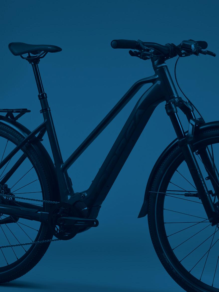
EN01|ES70|FR139|IT208|DE277 TECHNISCHES HANDBUCH
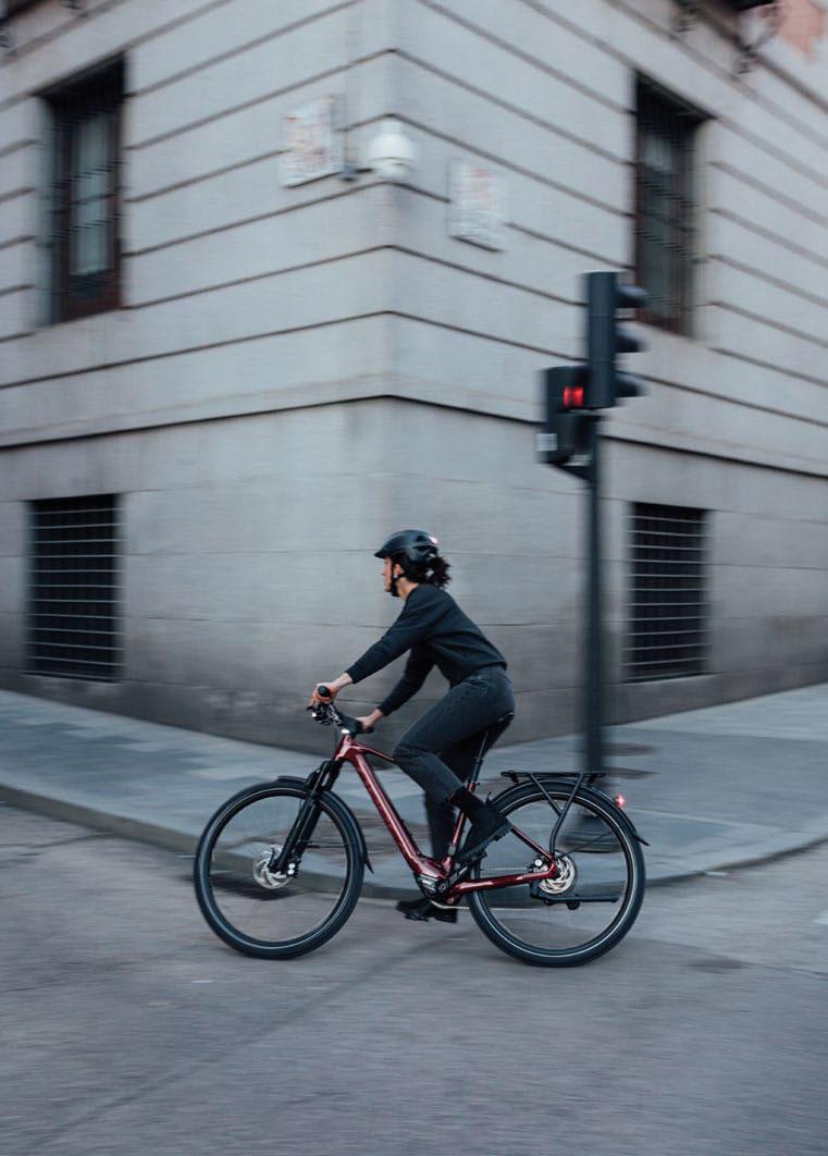
BLUE PAPER KEMEN 2022 2 | ORBEA ORBEA | 3 TECHNISCHES HANDBUCH DE 01 BEDEUTUNG DER SYMBOLE 7 02 ORBEA GARANTIE 8 Gesetzliche Gewährleistung 8 Lebenslange Orbea Garantie 8 Registriere dein Fahrrad 8 Gewährleistung auf Bestandteile des Motorsystems 9 Inanspruchnahme der Garantie 10 03 WARTUNG 11 Fahrrad reinigen 11 Kette schmieren 11 Überprüfung vor jeder Fahrt 11 Wartungsintervalle der Komponenten 12 Update des Motorsystems 14 Ersatzteile 14 Nach einem Sturz oder Aufprall 15 04 HINWEISE ZUR VERWENDUNG DES KEMEN 16 Maximale Reifengröße 16 Mindesteinschubtiefe der Sattelstütze 16 Maximale Länge der Gabel 16 Maximale Anzahl der Spacer am Vorbau 16 Position des Vorbaus am Gabelschaft 17 Empfohlener Einsatz 17 05 NUTZUNGSHINWEISE ZU BESTANDTEILEN DES MOTORSYSTEMS 18 Reichweite 19 06 BEDIENUNG DES KEMEN 21 Ein-/Ausschalten des Kemen 21 Zwischen Unterstützungsstufen umschalten 26 Ein-/Ausschalten der Beleuchtung 27 Systemwarnungen/-fehler 29 INHALT
BLUE PAPER KEMEN 2022 4 | ORBEA ORBEA | 5 TECHNISCHES HANDBUCH DE 07 SHIMANO ETUBE PROJECT CYCLIST 30 Personalisierung des EP8 Motorsystems 30 Anzeige von Systemfehlern 32 08 ORBEA RS TOOLBOX. DATENFELD FÜR GARMIN GERÄTE 33 Orbea RS Toolbox auf Garmin Geräten entsperren und installieren. Garmin Express (PC/Mac) 33 Orbea RS Toolbox Datenfeld auf deinem Gerät anzeigen 37 Orbea RS Toolbox verwenden 40 43 09 GEOMETRIE UND ERGONOMIE 44 Maximale und minimale Sitzhöhe bei Variostützen 46 10 TECHNISCHE DATEN 48 Technische Daten des Kemen 48 Daten der Bestandteile des Motorsystems 51 KOMPONENTEN, MONTAGE, NUTZUNG UND ERSATZTEILE 55 11 STEUERSATZ 55 Abmessungen des Steuerrohrs 55 Daten zum Steuersatz HS01 55 Steuersatzmontage und Komponenten 56 12 HINTERRADACHSE UND SCHALTAUGE 57 Kompatibilität mit Fahrradanhängern 57 13 PROTEKTOREN 58 14 KETTENBLATT 59 15 SONSTIGE RAHMENTEILE 60 16 FAHRRADSTÄNDER 61 17 VORBAU 62 Vorbau Orbea Urban ICR 35 62 Vorbaumontage und Komponenten 63 18 KABELFÜHRUNG FÜR MECHANISCHE KOMPONENTEN 64 19 MOTORSYSTEM 65 Anschlussschema der Komponenten 65 Kabelführung für Shimano Komponenten 68 Installation des Displays SC-EM800 auf Modellen mit SC-E5003 Kabelführung für Orbea RS Komponenten 72 Bestandteile des Motorsystems – Orbea RS und Shimano Komponenten 76 Kompatibilität von Bremsscheiben 77 Beleuchtung 81 Daten zur Beleuchtung 81 Montage eines Frontscheinwerfers am Vorbau 86 Montage des in den Steuersatz integrierten Lichts 86 Kabelführung und Anschluss der Komponenten 88 Bestandteile der Beleuchtungsanlage 91 Montage des EP8 Motors 92 Daten 93 95 Daten 100 Montage des Range Extender 101 Verbindung 102 Ladestand 104 Fehlercodes 105 Ersatzteile 106 Smart Charger RS 2 A - 4 A 107 Verbindung mit Etube Project Professional. Händlerinformationen 113 20 GEPÄCKTRÄGER UND SCHUTZBLECHE 116 KEMEN ASPHALT 116 Montage des vorderen Schutzblechs 118 KEMEN SUV 120 Montage des vorderen Schutzblechs 125 Komponenten und Ersatzteile 127 21 DÄMPFER 133 Einstellen der Fox und Marzocchi Gabeln 133 22 KONFORMITÄTSERKLÄRUNG 136 23 ZUSÄTZLICHE INFORMATIONEN 137
Dieses technische Handbuch enthält wichtige Informationen zu deinem Fahrrad, seiner Verwendung, seiner Wartung und seinen Ersatzteilen. Bitte lies es Bedienungsanleitungen zu Orbea Fahrrädern und Komponenten, welche de-teile der Fahrräder eingehen, um einen sicheren Betrieb zu ermöglichen. Diese
um Anleitungen, Warnhinweise zur Nutzung, Wartung und Montage zu verdeutlichen. Achte auf diese Symbole, um Gefahrensituationen zu vermeiden und die Handbuch wird das Symbol jeweils zusammen mit der für das betroffene Baudurch, um ihre Bedeutung zu verstehen.
Wichtige Informationen zu Einsatz, Wartung und Eigenschaften von Kompoauf der Website des entsprechenden Herstellers oder über dessen Vertrieb in
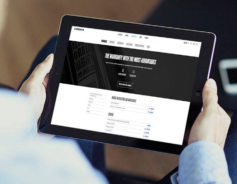
SICHERHEITSANWEISUNGEN
GEFAHR: Eine unmittelbar gefährliche Situation, die zum Tod oder zu schweren Verletzungen führt, wenn sie nicht gemieden wird.
WARNUNG: Eine möglicherweise gefährliche Situation, die zum Tod oder zu schweren gemieden wird.
VORSICHT: Eine möglicherweise gefährliche Situation, die zu leichten bis mittelsie nicht gemieden wird.
zung zusammenhängt. Wichtige Information.
GEFAHR EINES STROMSCHLAGS: Gefahrensituation, die zu schweren Verletzungen wenn sie nicht gemieden wird.
KURZSCHLUSSGEFAHR: Das Nichtbeachten
beschädigen oder in Brand setzen.
Die Symbole GEFAHR und WARNUNG weisen auf die Gefahr eines Unfalls hin, wenn die beschriebene Situation nicht gemieden wird. Ein Fahrradunfall birgt immer das Risiko schwerer oder gar tödlicher Verletzungen. In diesem Handbuch wird in Zusammenhang mit diesen Symbolen nicht jedes Mal auf die Todesgefahr hingewiesen, da diese hier ausführlich beschrieben wird.
Die zu verwendende Werkzeuggröße wird in dem entsprechenden Symbol dargestellt.
ANZUGSDREHMOMENTE: Das entsprechende Anzugsdrehmoment (in Newtonmeter) wird unter dem Symbol des für
ART DES VERBINDUNGSMITTELS
ÖL: Leichte Schmierung für Teile wie Ketten oder Züge.
FETT: Hochwertiges Montagefett zur VerFestsetzen einzelner Teile.
CARBONPASTE: Montagepaste für Carbonteile, um die Reibung zwischen den einzelnen Teilen zu erhöhen.
LOCTITE SERIE 600: Fixierung zylindrischer Teile.
LOCTITE SERIE 200: Fixiermittel oder Schraubensicherung. Mittelfest
LOCTITE SERIE 400:
BLUE PAPER KEMEN 2022 6 | ORBEA ORBEA | 7 TECHNISCHES HANDBUCH DE
6 6 10 N.m
01 BEDEUTUNG DER SYMBOLE
-
INBUSSCHLÜSSEL TORXSCHLÜSSEL KREUZSCHLITZSCHRAUBENDREHER
WERKZEUGE MAULSCHLÜSSEL
GREASE FIBER CARBON GRIP
GESETZLICHE GEWÄHRLEISTUNG


Orbea Fahrrads, der Starrgabel und Orbea-eigenen (OC) Komponenten eine gesetzliche Gewährleistung von drei
der im Land des Kaufs gesetzlich vorgeschriebenen Gewährleistungsfrist.
garantiert Reparatur oder Austausch des beschädigten -
in unseren Fahrrädern verbauten Rahmen und Starrgabeln für den im vorigen Abschnitt genannten Zeitraum ab.
auf unsachgemäßen Gebrauch, Stürze, Unfälle oder fehlende Wartung sowie die übliche Abnutzung von Teilen wie
Starrgabeln um ein Jahr nach Ablauf der gesetzlichen Gewährleistung.
Die gewerbliche, lebenslange Orbea Garantie gilt nur für Rahmen und Starrgabeln, nicht aber für OC-Komponenten oder andere Orbea-eigene Komponenten.
Die vollständige Beschreibung der Bedingungen der le-
www.orbea.com/gb-en/warranty/#orbea-lifetime-warranty
REGISTRIERE DEIN FAHRRAD
musst du dein Fahrrad innerhalb von 30 Tagen nach dem
www.orbea.com/es-es/acceso-registro?from=register-plate/
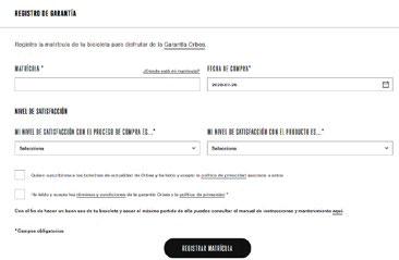
GEWÄHRLEISTUNG AUF BESTANDTEILE DES MOTORSYSTEMS
SHIMANO STEPS BESTANDTEILE
Die Bestandteile des Shimano STEPS Systems (Motor, Dis-belung) sind über die gesetzliche Gewährleistung ab Kauf Land des Kaufes geltende Frist der gesetzlichen GewährDiese Komponenten betreffende Gewährleistungsansprü-mano gerichtet werden.
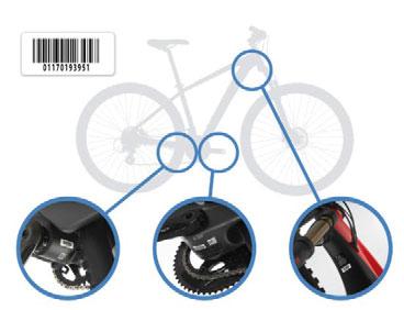
www.orbea.com/gb-en/warranty/
LEBENSLANGE ORBEA GARANTIE
Zusätzlich zur gesetzlichen Gewährleistung bietet Orbea
Registrierung des Fahrrads über die Orbea Website innerhalb von 30 Tagen nach dem Kauf eine gewerbliche, und Konformitätsfehler der von uns in unseren Fahrrädern verbauten Rahmen und Starrgabeln ohne zeitliche Befristung ab.
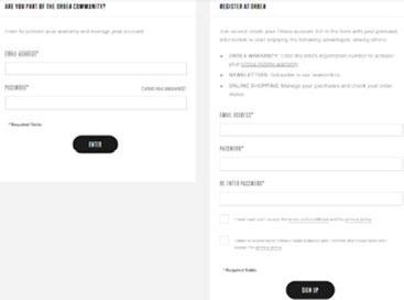
EXKLUSIVE ORBEA KOMPONENTENponenten) sind über die gesetzliche Gewährleistung ab die im Land des Kaufes geltende Frist der gesetzlichen GeGewährleistungsansprüche müssen über eine autorisierte und Orbea ab und garantiert die Reparatur oder den Aus-ten für die betroffene Kundin oder den Kunden.
auf unsachgemäßen Gebrauch, Stürze, Unfälle, fehlerhafte Installation oder fehlende Wartung oder Nichtbeachtung Range Extender) aufgrund der natürlichen Alterung der
BLUE PAPER KEMEN 2022 8 | ORBEA ORBEA | 9 TECHNISCHES HANDBUCH DE
-
02 ORBEA
GARANTIE
01. DEIN KONTO ANMELDEN
02. REGISTRIERE DEINE RAHMENNUMMER
03. HIER FINDEST DU DEINE RAHMENNUMMER
INANSPRUCHNAHME DER GARANTIE
Alle Garantiefälle müssen über eine autorisierte Orbea durchführt und sämtliche für die vollständige Prüfung des Falls benötigten Unterlagen an Orbea, Shimano oder den Hersteller der betroffenen Komponenten weiterleitet. Die über den Bearbeitungsstatus sowie die von Orbea, Shimano oder dem Komponentenhersteller bezüglich des Garantiefalls getroffene Entscheidung.
GARANTIEANSPRÜCHE UND REPARATUR
VON BESTANDTEILEN DES MOTORSYSTEMS
SHIMANO: -
paraturen der folgenden Bestandteile des Motorsystems
· Motor Shimano EP8.
· Display SC-EN800, SC-E7000 oder SC-E5003.
· Spezielle Kabel für Shimano STEPS/Di2.
· Schalter zum Wechsel der Unterstützungsstufe SWEM800L / EM7000-L.
ORBEA: -
03 WARTUNG
Wir empfehlen, zur Geltendmachung eines Garantiefalls -
se wende dich an den beim Kauf gewählten Fachhandel. -
www.orbea.com/es-es/distribuidores/?country
www.orbea.com/es-es/contacto/
unsere Rahmen und Gabeln aus Carbon und Aluminium sämtliche Teile deines Rades regelmäßig gewartet werden.tioniert, sicher ist und du lange Spaß damit hast.
FAHRRAD REINIGEN
Reinige dein Fahrrad regelmäßig mit Wasser und sanfterden Rahmen beschädigen.
empfehlen sich fettlösende, biologisch abbaubare Reiniger auf Zitrusbasis.
Über längere Zeit an deinem Fahrrad angeder Komponenten erschweren und dazu fühbleiben und so zu Problemen oder gar Unfällen führen.
Außerdem mindert angesammelter Schmutz sogar zu Beschädigungen des Rahmens führen, besonders im Bereich der Lager und
Verzichte auf Schmiermittel in Form vongen. Entsprechend solltest du die Bremsen nach jedem Schmiervorgang überprüfen.
ÜBERPRÜFUNG VOR JEDER FAHRT -
prüfung unterziehen. So stellst du sicher, dass es einwand-
dem Motor und der Ladebuchse.
· Im Steuersatz integriertes Licht.
KETTE SCHMIEREN
Nach der Reinigung deines Fahrrads solltest du die Kette schmieren. Verwende so wenig Schmiermittel wie möglich zur Behandlung der Kettenglieder und nimm überschüssiges Schmiermittel wieder auf. So vermeidest du die vermehrte Ablagerung von Schmutz, welche nicht nur die auch die Lebensdauer der Komponenten mindert.
RAHMEN: Überprüfe Rahmen und Gabel auf Schäden oder Risse sowie ungewöhnliche Geräusche. Solltest du irgendwelche Beschädigungen feststellen, darfst du das Fahrrad nicht mehr verwenden und solltest dich mit deiner überprüfen zu lassen.
KETTE: Die Kette sollte sauber und gut geschmiert sein,ursachen.
BREMSEN: Stelle sicher, dass die Bremsen ordnungsge-ten Sitz der Schrauben.
REIFEN: Überprüfe die Reifen auf Verschleiß und Schnitte -
LAUFRÄDER: Überprüfe, ob die Laufräder gleichmäßig und ohne Seitenschlag laufen. Ziehe die Laufräder leicht oder Schnellspanner sicher und mit dem richtigen Drehmoment angezogen sind.
STEUERSATZ: Ziehe die Vorderradbremse und bewege das Vergewissere dich, dass weder ungewöhnliche Geräusche
BLUE PAPER KEMEN 2022 10 | ORBEA ORBEA | 11 TECHNISCHES HANDBUCH DE
-
DREHPUNKTE DES HINTERBAUS: Überprüfe bei vollgefe-
Hinterbau erst zur einen und dann zur anderen Seite des Fahrrads und achte dabei auf ungewöhnliche Geräusche sauber arbeiten oder Spiel aufweisen, solltest du die Anes sein, dass die Lager verschlissen oder beschädigt sind.
LAGER: Bei den Lagern eines Fahrrads (Tretlager, Drehhandelt es sich um Verschleißelemente, die regelmäßig
Lager die Komponenten, in welche sie eingebaut sind, Verschleiß der Lager beschleunigen. Lager, die Spiel aufweisen oder nicht sauber laufen, müssen umgehend ersetzt werden. Wende dich im Zweifelsfall an deine Ver-
Schäden an Teilen deines Fahrrads, wie etwa dem Rahmen oder den Laufrädern etc., die sich auf fehlende Wartung und Austausch der
Überprüfe, ob Fehler im Motorsystem vorliegen. In diesem Fall zeigt das Display SC-EN800 bzw. SC-E5003 einen entsprechenden Fehlercode an. Bei Modellen, die mit dem du das Fahrrad über Bluetooth mit der Smartphone-App Etube Project Cyclist verbinden, um mehr über den Fehler- oder Warncode zu erfahren und Informationen zur Problemlösung zu erhalten. Falls der Fehler auch nach Befolgen der Lösungsvorschläge aus App oder STEPS Systemhandbuch weiter bestehen sollte, bring dein Fahrrad für eine vollständige Überprüfung und Reparatur zu einer
Das Display SC-E5003 von Shimano besitzt
bei Modellen, die mit diesem Display ausgestattet sind, das Fahrrad nicht mit der App verbinden. Für Informationen zur Problemlösung bei einem Fehler oder einer Warnung schlage den Code in der Shimano STEPS Gebrauchsanweisung nach oder bringe dein Fahrrad zu einer autorisierten Shimano Ver-
führen oder das Originaldisplay gegen ein SC-EM800 Display austauschen zu lassen.
WARTUNGSINTERVALLE DER KOMPONENTEN
Die im Folgenden für die Komponenten angegebenen Wartungsintervalle dienen der denen das Fahrrad genutzt wird (widrige der Komponenten und die WartungsintervalFahrrads und seiner Komponenten (Schmutz-schleiß der Komponenten), Einsatz destervalle). Die empfohlenen oder vorgeschriebenen Wartungsintervalle zu Komponenten anderer Hersteller, die an deinem Orbea Fahrrad verbaut sind, erfährst du auf der Website des Herstellers oder beim Vertrieb
hinaus abgenutzte Kette muss zur Vermeidung vontauscht werden. Das Missachten der Anweisungen des werden müssen.
LAUFRÄDER:
· Ausbau und manuelle Überprüfung der Lager und aller Bauteile alle sechs Monate, die das Fahrrad genutzt wird.
DÄMPFER UND FEDERGABEL:
oder jährlich (je nachdem, welcher Fall früher eintritt)
VARIOSTÜTZEN:
oder jährlich (je nachdem, welcher Fall früher eintritt)
DREHPUNKTE IN RAHMEN VOLLGEFEDERTER
MOTORSYSTEM: Schalte das Rad ein und überprüfeprüfe, ob der Motor Unterstützung liefert und ob alle Komponenten (Motor, Display, Schalter zum Wechsel dersämtliche Verbindungen zwischen den einzelnen Komponenten des Motorsystems sowie den Zustand der Komponenten und Kabel. (Kabel und Komponenten, die Anzeichen von Beschädigungen aufweisen, müssen ausgetauscht werden.)
der Warn- und Fehlercodes bei Shimano STEPS sowie eine Die Missachtung der hier geschilderten Anweisungen und die Verwendung eines Fahrrads, das die hier beschriebenen Problemezungen nach sich ziehen.
Anzugsdrehmomente und montiere die Komponenten gemäß der in diesem Handbuch angegebenen Anzugsdrehmomente. Folge den empfohlenen Anzugsdrehmomenten für Komponenten anderer Hersteller, die an deinem Orbea Fahrrad verbaut sind. Die Missachtung -
nenten, Unfällen und zum Tod führen.
Die Nichteinhaltung der Wartungsintervalleren, die nicht über die Gewährleistung von Orbea oder des Herstellers der Komponen-
Das Nichteinhalten der Wartungsintervallechen und zu Verletzungen und Unfällen führen.
STEUERSATZ:
· Ausbau und manuelle Überprüfung der Lager alle sechs Monate, die das Fahrrad genutzt wird.
TRETLAGER:
· Ausbau und manuelle Überprüfung der Lager alle sechs Monate, die das Fahrrad genutzt wird.
ANTRIEB:
· Regelmäßige Überprüfung der Abnutzung der Kette alle 500 Kilometer. Eine über die Herstellerempfehlungen
FAHRRÄDER:
· Ausbau und manuelle Überprüfung sämtlicher Lager alle 125 Stunden oder jährlich (je nachdem, welcher Fall früher eintritt). Je nachdem, unter welchen Bedin-
Fahrrads oder der Einsatz unter widrigen Wetterbedingungen oder im Schlamm erfordert den Ausbau und die Überprüfung des Rahmens alle 75 Stunden oder alle sechs Monate (je nachdem, welcher Fall früher eintritt). Läuft ein Lager nicht sauber oder weist Spiel auf, muss es umgehend ersetzt werden.
SCHALTZÜGE UND ZUGHÜLLEN:
· Je nachdem, bei welchen äußeren Bedingungen das Fahrrad genutzt wird, müssen die Schaltzüge alle 6 bis 12 Monate, die das Fahrrad genutzt wird, erneuert werden.
BREMSEN:
BLUE PAPER KEMEN 2022 12 | ORBEA ORBEA | 13 TECHNISCHES HANDBUCH DE
-
-
-
· Überprüfung der Abnutzung der Bremsscheiben und Monate, je nachdem, bei welchen äußeren Bedingungen das Fahrrad genutzt wird. Jährliches Entlüften der Bremsleitungen.
BESTANDTEILE DES MOTORSYSTEMS:
Regelmäßige Überprüfung von Verbindungen und Kabeln des Motorsystems deines Fahrrads. Die Anschlüsse müsmüssen in gutem Zustand und frei von Schnitten oder
display auch durch das Display SC-EM800 von Shimano ersetzt werden.
Die Verwendung nicht originaler Ersatzteile oder Unfälle mit schweren Folgen nach sich
Die Montage einiger der in diesem Handbuch beschriebenen Ersatzteile übersteigtnen. Wende dich zur Wartung deines Fahrrads und seiner Komponenten stets an eine
System auf mögliche Updates zu prüfen, wenn du dein E-
der Ersatzteile besitzt. Eine unsachgemäß
Rahmen und Gabeln aus Carbon sind besonders steif und belastbar. Aber bei Überlastung oder einem Schlag auf das Material verbiegen sich die Carbonfasern nicht, sondern brechen. Selbst wenn die Schäden mit
derart beschädigen, dass es zu einem späirgendwelchen Zweifeln über den Zustand des Materials nach einem Sturz oder Unfall solltest du auf jeden Fall deine Orbea Ver-
„Nutzungshinweise“ und „Wichtige Informati-
UPDATE DES MOTORSYSTEMS:
weise zu verbessern. Einige Updates des Shimano STEPS Systems werden per Bluetooth® ausgeführt, wenn du dein Fahrrad mit der Smartphone-App Etube Project Cyclist von Shimano verbindest.
Bei der Durchführung eines Systemupdates per Bluetooth® mit der Smartphone-App Etube Project Cyclist wird empfohlen, alle
chung des Updates durch eingehende Anrufe oder Nachrichten zu vermeiden.
Im Falle einer Unterbrechung des Updates und daraus resultierender Systemstörung bringe dein Fahrrad zu einer autorisierten Or-
Das Display SC-E5003 von Shimano besitzttem also nicht über Bluetooth mit der App dein Fahrrad zu einer autorisierten Orbea oder Updates verfügbar sind. Das wird festgestellt, indem das System über das Interface SMPCE02 mit der Shimano Software Etube Prodas Originaldisplay auch durch ein SC-EM800 Display von Shimano ersetzen.
Einige der hier beschriebenen Prüfungen und Wartungsarbeiten übersteigen die Kenntdich zur Wartung deines Fahrrads und seinerstelle, falls du nicht selbst über die notwen-tungsarbeiten verfügst. Eine unsachgemäß oder Unfällen mit schweren Folgen führen.
Eine unsachgemäß durchgeführte Wartungten führen, die nicht durch die gesetzliche
ERSATZTEILE
Verwende stets Originalersatzteile von Orbea, Shimano oder dem Hersteller der betroffenen Komponenten.
zu Verletzungen oder Unfällen mit schweren Folgen führen.
zu Beschädigungen an deinem Fahrrad führen, die nicht durch die gesetzliche Gewähr-
NACH EINEM STURZ ODER AUFPRALL
Stürze gehören zum Radsport dazu. Falls du einen Unfall mit deinem Orbea Fahrrad erleidest, solltest du dich zunächst vergewissern, dass mit dir soweit alles in Ordnung ist. Bitte um ärztliche Hilfe, falls dies notwendig sein sollte.terfahrt unbedingt den Zustand deines Fahrrads überprüfen.
UNTERSUCHE DEN RAHMEN UND DIE KOMPONENTEN DEINES FAHRRADS AUF SCHÄDEN
Setzte deine Fahrt nicht fort, falls du eine Beschädigung feststellst.
ZU ÜBERPRÜFENDE ELEMENTE
Untersuche, ob Rahmen oder Gabel gebrochen oder ver-den, musst du die Verwendung des Fahrrads umgehend einstellen. Prüfe Carbonrahmen auf Risse oder weiche Stellen im Carbon. Solltest du eine entsprechende Stellestellen.
Überprüfe die Schaltung und die Laufräder und stelle si-
auf ungewöhnliche Geräusche deines Fahrrads achten. falls du solch ungewöhnliche Geräusche feststellen soll-
BRING DEIN FAHRRAD ZU EINER AUTORISIERTEN ORBEA VERKAUFSSTELLE, UM EINE PROFESSIONELLE INSPEKTION DURCHFÜHREN ZU LASSEN
Manche Folgen eines Sturzes oder Unfalls lassen sich nurbaut und auf Schäden untersucht wird. -
digen und zu Materialversagen oder vorzeitigem Verschleiß führen. Ein Materialverauftreten und den Kontrollverlust über das Fahrrad, schwere Verletzungen oder sogar den Tod nach sich ziehen.
BLUE PAPER KEMEN 2022 14 | ORBEA ORBEA | 15 TECHNISCHES HANDBUCH DE
-
-
-
-
-
HINWEISE ZUR VERWENDUNG DES KEMEN
MAXIMALE REIFENGRÖSSE
Dieses technische Handbuch beschreibt die maximale Größe von Reifen, die in diesem Rahmen montiert werden dürfen. Diese Angaben sind bei der Montage eines Reifens an deinem Fahrrad unbedingt zu beachten.
allerdings von Hersteller zu Hersteller abweichen. Falls du einen Reifen montierst, der nicht der Originalbereifung deines Fahrrads entspricht, musst du sicherstellen, dass -
destens 6 mm Abstand zum Rahmen hat.
Schäden am Rahmen oder an Komponenten, -
führen sind, der nicht den beschriebenen Abmessungen entspricht, sind nicht durch die
MINDESTEINSCHUBTIEFE DER SATTELSTÜTZE
Halte dich immer an die Angaben zur Mindesteinschubtiefe der verwendeten Satteldas Material über die Grenzwerte belasten, für die es ausgelegt wurde, und so zu nichtterialversagen führen, welches Unfälle und
MAXIMALE LÄNGE DER GABEL (ACHSE BIS KRONE)
Halte dich immer an die Angaben zur maximalen Länge der Gabel, die im Abschnitt „Technische Daten“ in diesem Handbuch aufgeführt werden. Die maximale Länge der Gabel bezieht sich auf den Abstand zwischen der Achse der Gabel und der Unterseite des Steuerrohrs (Achse bis Krone).
Beachte auch den maximalen zulässigen Federweg der Federgabel im Abschnitt „Technische Daten“ dieses Handbuchs.
Die Missachtung dieser Maße und der Einbau von Gabeln, die länger sind als maxiGrenzwerte belasten, für die er ausgelegtren, welches Unfälle und schwere Verletzun-
POSITION DES VORBAUS AM GABELSCHAFT
EMPFOHLENER EINSATZ
Sämtliche Modelle sind für den Einsatz nach ASTM Level 2 zugelassen, was Level 1 sowie unbefestigte Straßen und Schotterstraßen und -wege mit mäßiger Steigung einschließt. Drops sind dabei auf 15 cm begrenzt.
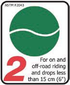
Nutzerhandbuch.
MAXIMALE ANZAHL DER SPACER AM
VORBAU
Verwende niemals mehr als die für deinen Rahmen angegebenen Steuersatzspacer un-
erfährst du, wie viele Steuersatzspacer der Orbea Rahmen maximal erlaubt. Der Einsatz von mehr als den maximal erlaubten Spacern -
Die Länge des Gabelschafts muss immer der Position des Vorbaus am Gabelschaft entsprechen. Der Vorbau muss immer so am Gabelschaft montiert werden, dass sich die beiden Schrauben am Ende des Vor-
Montiere den Vorbau nie so, dass sich die obere Schraube oberhalb des Abschlusses
Material über die Grenzwerte belasten, für -
BLUE PAPER KEMEN 2022 16 | ORBEA ORBEA | 17 URBAN/ GENERAL PURPOSE L O.K. NOT O.K. TECHNISCHES HANDBUCH DE 04
NUTZUNGSHINWEISE
ZU BESTANDTEILEN DES MOTORSYSTEMS PFLEGEHINWEISE UND VORGABEN
ZUR NUTZUNG DER BESTANDTEILE DES MOTORSYSTEMS UND DER AKKUS
Im Kapitel „Wichtige Informationen zu denge Extender.
Bauteile sind vor Spritzwasser und Regen geschützt.
die Bauteile beschädigen und Kurzschlüsse verursachen.
· Vermeide den Einsatz deines Fahrrads bei sehr schlech-
Einsatz bei sehr schlechtem Wetter dazu führen, dass
· Bei Regen sollte der ungeschützte Transport des Fahrrads auf dem Fahrradträger am Auto vermieden wer-
· Halte dich an die empfohlenen Temperaturbereiche für-
Die folgende Übersicht zeigt die maximalen Temperaturbe-
Generell die Aufbewahrung der Akkus bei Temperaturen unter 0 °C die Reichweite pro Ladezyklus und kann langfristig die Lebensdauer des Akkus beeinträchtigen.
TEMPERATURBEREICHE
das Ladegerät angeschlossen sein. Zudem sollte der Ladevorgang stets so beaufsichtigt werden, dass das
Bedienungsanleitung:
um/7HC0B/UM-7HC0B-000-ENG.pdf
Händlerhandbuch:
EP800/DM-EP800-03_ENG.pdf
0 ºC - 40 ºC
Entladen (Nutzung) -10 ºC - 40 ºC
Aufbewahrung
Wird das Fahrrad auf dem Fahrradträger am Auto transportiert, sollte der Range Extender vom Fahrrad entfernt und der ordnungsgemäße Verschluss der Ladebuchse überprüft werden.
gere Zeit hohen Temperaturen aussetzen. Die hohen
· Vermeide die längere Aufbewahrung deines Fahrrads alle drei Monate den Ladestand und lade ihn ggf. wieder vermeiden.
NUTZUNG DES AKKUS BEI EINEM LADESTAND UNTER 10 %: -
bensdauer der Zellen und die Ladebalance beeinträchtigen.
einen sorgenfreien Einsatz ermöglicht. Es wird jedoch empfohlen, den Ladevorgang zu überwachen, um Schä-
oder verwendet werden. Wende dich an eine autorisierdurchführen zu lassen.
Anschlüsse beschädigt werden.
schlusses der Ladebuchse, um das Eindringen von zu befreien. Vermeide es, bei diesem Vorgang die Anschlüsse der Ladebuchse zu beschädigen.
Im Kapitel „Wichtige Informationen zu den
ge Extender.
REICHWEITE-
gem Gewicht und Abmessungen maximale Reichweite zu ermöglichen. Die pro vollständiger Ladung verfügbare
· Unterstützungsstufe: Der Einsatz höherer Unterstützungsstufen vermindert die verfügbare Reichweite.
· Das über die Shimano Etubedie verfügbare Reichweite. So hebt die Wahl des Unter-fen an und reduziert entsprechend die Reichweite.
· Individuelle Anpassung der Unterstützungsstufen: Die ungefähren Reichweitenangaben beziehen sichbea vorgenommenen Originaleinstellungen. Die Anpassung der Unterstützungsstufen über die Shimano
Zur Anpassung der Unterstützungsstufen bei Modellen, die mit dem Display SC-E5003 von Shimano ausgestattet sind, muss das Fahrrad über das Interface SM-PCE02 mit der Shimano Software Etube Project Professional verbunden werden.
BLUE PAPER KEMEN 2022 18 | ORBEA ORBEA | 19 TECHNISCHES HANDBUCH DE
-
05
-
-
-
-
-
-
der Smartphone-App Etube Project Cyclist verbunden werden. Bringe dein Fahrrad zu
um Änderungen vorzunehmen oder das Originaldisplay durch ein SC-EM800 Display von Shimano zu ersetzen.

Temperaturen:
weite pro vollständiger Ladung.
· Gesamtgewicht von Radfahrer:in/Ausrüstung/Gepäck.
· Erbrachte Pedalierleistung.
Untergrund und Anstiege: Der Einsatz auf unbefes-
weite pro vollständiger Ladung.
UNGEFÄHRE REICHWEITEN:
In der folgenden Tabelle sind ungefähre Reichweitenwerte angeführt, wobei von einem unbeladenen Gepäckträger ausgegangen wird. Berücksichtige auch die im voranstehenden Abschnitt angeführten Faktoren, die sich auf die tatsächlich verfügbare Reichweite auswirken können.
INTEGRIERTER AKKU. 540 Wh
UNTERSTÜTZUNGSSTUFE ECOTRAILBOOST
UNGEFÄHRE ANSTIEGSLEISTUNG (Höhenmeter) 3.5002.2001.600
MIT RANGE EXTENDER 792 Wh (540 + 252 Wh)
TRANSPORT VON E-BIKE-AKKUS
06 NUTZUNG DES KEMEN
des Shimano STEPS EP8 Systems im Kemen sowie die ex-
Beachte auch das Handbuch zum Shimano STEPS EP8
erfolgen. Sie dürfen nur in der zugelassenen Originalver-
über die in deinem Land geltenden Regelungen zu Handhabung und Transport solcher Güter.
Falls der Range Extender zur Prüfung oder Reparatur
um/7HC0B/UM-7HC0B-000-ENG.pdf
Sämtliche Gebrauchsanweisungen und Händlerhandbü-
ANZEIGE DES AKKU-LADESTANDS
Ausstattung auf verschiedene Arten angezeigt werden.
KOMBINIERTER LADESTAND VON INTEGRIERTEM AKKU UND RANGE EXTENDER:
UNGEFÄHRE REICHWEITE/UNGEFÄHRE
NSTIEGSLEISTUNGstiegsleistung
erfolgen. Orbea unterstützt dich bei der Suche nach der besten Lösung.
Solltest du das Sicherheitsdatenblatt (MSDS) zu den RS -
unternehmen diese Informationen verlangen, wende dich
TRANSPORT VON E-BIKES
Informiere dich über die für die entsprechende Fluggesellschaft geltenden Regelungen zum Transport von 100 Wh.
Solltest du das Sicherheitsdatenblatt (MSDS) zu den RSunternehmen diese Informationen verlangen, wende dich
Gib einfach den Namen der Komponente in das Suchfeld ein, um die zugehörige Gebrauchsanweisung, Händlerbetriebsanleitung, Ersatzteile usw. abzurufen.
EIN-/AUSSCHALTEN DES KEMEN
Ist der Range Extender mit dem Fahrrad verbunden, benachfolgend beschriebenen Arten angezeigte LadestandNutzungsempfehlungen für den Range Extender am Kemen.
MIT DISPLAY SC-EM800 ODER SC-E5003 VON SHIMANO
Ist das SC-EM800 oder SC-E5003 Display verbaut, wird
am Knopf erlischt.
KOMPATIBLE GARMIN GERÄTE. ORBEA RS TOOLBOX
Über die App Orbea RS Toolbox lassen sich die wesentli-min Radcomputer anzeigen, darunter auch der Ladestand
BLUE PAPER KEMEN 2022 20 | ORBEA ORBEA | 21 3 sec. OFF TECHNISCHES HANDBUCH DE -
-
-
-
100% - 81% 80% - 61% 60% - 41% 40% - 21% 20% - 1% 0% SC-EM800 SC-E5003
nicht in Prozent in der App Orbea RS Toolbox erscheinen, werden diese Daten wieder anIn diesem Moment meldet das EP8-System an das Garmin Gerät, auf welchem er dann
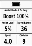
rad auch aus- und wieder einschalten (bei eingeschaltetem Garmin Gerät), um die Ver-stand auf deinem Garmin Gerät anzuzeigen.
Nähere Informationen zu Download und Installation der App Orbea RS Toolbox auf deinem Garmin Gerät erhältst du im entsprechenden Abschnitt dieses Handbuchs.
Range Extender 252 Wh.
mal auf die Haupttaste am Orbea RS Range Extender. Die
Beim Kemen, Urrun und Rise Hydro 2022 wird der gleiche
des Ladegeräts dauerhaft blau.


ausgestattete Modelle nicht mit Garmin Geräten verbunden werden, auf denen das Datenfeld Orbea RS Toolbox installiert ist. Um bei diesen Modellen eine Verbindung zu Garmin Geräten herzustellen, muss das Originaldisplay durch das Display SC-EM800 von Shimano ersetzt werden.
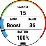
ORBEA RS AKKUS
Integrierter Akku 540 Wh.
nicht mit den Modellen des Rise Carbon 2021Rise Carbon 2021-2022 verwendete Range
patibel.
Kemen, Urrun und Rise Hydro 2022 verwenExtender 252 Wh 2022, nur die Länge des verschiedenen Rahmen unterschiedlich. InforRange Extender in diesem Handbuch.
Ladegeräts muss zur Oberseite der Ladebuchse gerichtet sein. Die LED am Ladegerät leuchtet daraufhin zwei Se-ERROR!
100% Wenn die LED am Ladegerät beim Anschlussrend des Ladevorgangs rot leuchtet, liegt eine Störung vor. Trenne das Ladegerät umgehend ab und lies die in diesem Handbuch empfohlenen Maßnahmen zur Störungsbeseitigung am Ladegerät. Sollte sich das Problem nicht beheben lassen, setze dichbindung.
schrieben überprüft werden.
Nutzungsempfehlungen für den Range Extender am Kemen.
AUFLADEN DER AKKUS
tender vor dem ersten Einsatz deines Fahrrads vollständig auf.
INTEGRIERTER ORBEA RS AKKU 540 WH
Der Smart Charger des Kemen ist nicht mit -


Das Ladegerät des Rise Carbon 2021-2022

BLUE PAPER KEMEN 2022 22 | ORBEA ORBEA | 23 TECHNISCHES HANDBUCH DE
-
-
-
-
-
-
Trenne das Ladegerät von der Ladebuchse des Fahrrads, Ladebuchse sauber abschließt. Während das Ladegerät nicht einschalten. Möchtest du den genauen Ladestand ablesen, musst du das Ladegerät von der Ladebuchseladestand dann am Shimano Display ablesen.
EXTERNER AKKU RANGE EXTENDER
Der Smart Charger des Kemen ist nicht mit -
Das Ladegerät des Rise Carbon 2021-2022
Kemen, Urrun und Rise Hydro 2022 wird der gleiche RS Smart Charger verwendet.
des Ladegeräts dauerhaft blau.


das Ladegerät angeschlossen sein. Zudem sollte der Ladevorgang stets so beaufsichtigt werden, dass das
an das Ladegerät angeschlossen sein. Zudem sollte der Ladevorgang stets so beaufsichtigt werden, dass
Nutzungsempfehlungen für den Range Extender am Kemen. -
der nicht mit dem Ladegerät verbunden ist.
100%
Während der Range Extender aufgeladen wird, zeigen die
werden so vor Beschädigung geschützt, was einen sorgenfreien Einsatz ermöglicht. Es wird jedoch empfohlen, den Ladevorgang zu überwachen, um Schäden durch ein de-
werden so vor Beschädigung geschützt, was einen sorgenfreien Einsatz ermöglicht. Es wird jedoch empfohlen, den Ladevorgang zu überwachen, um Schäden durch ein de-
sich der RS Smart Charger ab, sobald der Range Extender muss das Ladegerät zunächst vom Stromnetz getrennt werden. Durch Wie-
Ladebuchse am Fahrrad (sofern angeschlossen), indem du zuerst die Sicherungslaschen am Kabel gegen den Uhrzeigersinn drehst und anschließend vorsichtig am Kabel ziehst. Verbinde nun das Ladegerät mit dem Range Extender. Achte -
se am Range Extender ausgerichtet sind. Die LED am Lade-


Entladen (Nutzung) und die Aufbewahrung.
Ladegeräts vorsichtig abziehst. Soll der Range Extender nun am Fahrrad eingesetzt werden, verbinde das Range Extender-Kabel mit dem Range Extender und der Ladebuchse am Fahrrad. Halte dabei die Sicherungslaschen
he die Laschen dann im Uhrzeigersinn, um die Verbindung zu sichern.
sich der RS Smart Charger ab, sobald der Range Extender muss das Ladegerät zunächst vom Stromnetz getrennt werden. Durch Wie-
Wird das Ladegerät zwischen Ladevorgängen Strom versorgt.
Entladen (Nutzung) und die Aufbewahrung.
Im Kapitel „Wichtige Informationen zu den
ge Extender.
BLUE PAPER KEMEN 2022 24 | ORBEA ORBEA | 25 TECHNISCHES HANDBUCH DE
-
--
-
-
-
-
-
Für ein deinen persönlichen Bedürfnissen entsprechendes -
zungsstufen über die Smartphone-App Shimano Etube Project Cyclist angepasst werden.
Der Shimano EP8 Motor verfügt über zwei Unterstützungs-
zungsstufen wiederum über die Smartphone-App Shimano Etube Project Cyclist individuell angepasst werden.
EINSTELLEN DER UNTERSTÜTZUNGSSTUFE
Zum Wechsel der Unterstützungsstufe mit dem Schalter SW-EM800 (Systeme mit dem Display SC-EM800) oder dem Unterstützungsstufe auszuwählen. Die höchste verfügbare Y, um eine niedrigere Unterstützungsstufe auszuwählen. · OFF
SCHIEBEHILFE -
zungsstufenschalter SW-EM800 bzw. den Knopf Y am auf dem Display EM800 erscheint bzw. das Symbol für die Schiebehilfe auf dem Display E5003 angezeigt wird.
Shimano App Etube Project Cyclist in diesem Handbuch.
dest du im vollständigen Handbuch von Shimano unter Bei Modellen, die mit dem Shimano Display
Bei Anschluss eines externen Range Extender die Parameter der Unterstützungsstufen über die Shimano Etube Project Cyclist App oder Etube Project Professional anzupassen. Mehr dazu erfährst du im Abschnitt zum Range Extender in diesem Handbuch.
EIN-/AUSSCHALTEN DER BELEUCHTUNG
Im Abschnitt „Beleuchtung“ in diesem Handbuch erfährst du mehr über die Lichter am Kemen.
TAGFAHRLICHTER
Das Benutzerhandbuch zum Display SC-E5003 von Shi-
Beim Display SC-EM800 wird der Name der ausgewählten Unterstützungsstufe auf dem Bildschirm angezeigt. Beim Display SC-E5003 wird die ausgewählte Unterstützungs-
zeigt. Je mehr Segmente leuchten (maximal drei), desto
um/7HU0B/UM-7HU0B-000-ENG.pdf
Das Benutzerhandbuch zum Display SC-EM800 von um/7H90B/UM-7H90B-001-ENG.pdf
Verbindung zur App Etube Project Cyclist hergestellt werden. Wenn du bei einem solchen Modell die Unterstützungsleistung der Unterstützungsstufen anpassen möchtest, musst du dein Fahrrad zu einer autorisierten
Dort wird das System über das Interface SM-PCE02 mit der Software Etube Project Professional verbunden, um die notwendigen
das Originaldisplay durch das Display SCEM800 von Shimano ersetzt werden.
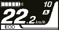

dass es für jede Unterstützungsstufe die größtmögliche Unterstützungsleistung liefert.
miert, die weniger Unterstützung durch das System benötigen. Es wird folglich mehr Eigenleistung gefordert.
schalten sich automatisch ein.
geschaltet werden.
nicht ausgeschaltet werden. Wenn das Fahrrad ausgeschaltet wird, schalten sich die Tagfahrlichter automatisch aus.
VERHALTEN DES HINTEREN TAGFAHRLICHTS BEIM BREMSEN:
Das hintere Tagfahrlicht des Kemen besitzt einen Beschleunigungssensor, der bei plötzlicher Verzögerung für ein helleres Licht sorgt. Dieses Licht ist nicht als Bremslicht zu betrachten, da es nicht mit dem Bremshebel verbunden ist.
LEZYNE FRONTSCHEINWERFER
schalten (je nach Modell des Kemen variiert das Scheinwerfermodell).
BLUE PAPER KEMEN 2022 26 | ORBEA ORBEA | 27 Y (1 sec) SC-EM800 SC-E5003 Y (Press&Hold) WALK X Y OFF > ECO > TRAIL > BOOST BOOST > TRAIL > ECO > OFF SC-EM800 SC-E5003 TECHNISCHES HANDBUCH DE
· ECO · TRAIL · BOOST
-
-
-
-
Abblendlicht umschalten.

Zum Ausschalten des Frontscheinwerfers halte den Len-
Wenn das Fahrrad ausgeschaltet wird, schaltet sich der Frontscheinwerfer automatisch aus.
EIN-/AUSSCHALTEN DER BELEUCHTUNG ÜBER DAS SHIMANO DISPLAY (Option nicht aktiv) -
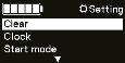
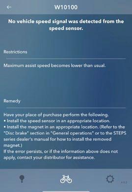
Shimano Interface SM-PCE02 mit dem Tool Etube Projectoption dann von IMMER EIN auf TASTE umgestellt werden.
Bei Auswahl der Option TASTE schaltet sich das Tagfahrlicht nicht mehr automatisch beim Starten des Fahrrads ein und der Lezyne Frontscheinwerfer bleibt ausgeschaltet. Die Beleuchtung muss nach dem Starten des Fahrrads zunächst über das Shimano Display eingeschaltet werden.
Im Abschnitt „Verbindung zu Etube Professional“ in dieser Anleitung erfährst du, wie das Kemen über das Interface SM-PCE02 von Shimano mit Etube Professional verbunden wird.

SYSTEMWARNUNGEN/-FEHLER
wird, zeigt das Display SC-EM800 bzw. SC-E5003 den entsprechenden Fehler- oder Warncode auf dem Bildschirm an. Schalte das Fahrrad einmal aus und wieder ein und verbinde es mit der Etube-Project-App. Der Fehler- bzw. Warncode und die Vorgehensweise zur Fehlerbehebung werden im Ab-
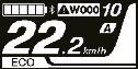
zu den Fehlercodes und möglichen Abhilfemaßnahmen sind


Das Display SC-E5003 von Shimano besitzt bei Modellen, die mit diesem Display ausgestattet sind, das Fahrrad nicht mit der App verbinden. Für Informationen zur Problemlösung bei einem Fehler oder einer Warnung schlage den Code in der Shimano STEPS Gebrauchsanweisung nach oder bringe dein Fahrrad zu einer autorisierten Shimano Ver-

naldisplay auch gegen ein SC-EM800 Display ausgetauscht werden.
der Warn- und Fehlercodes bei Shimano STEPS sowie eine Beschreibung der Vorgehensweise zur Problemlösung:

BLUE PAPER KEMEN 2022 28 | ORBEA ORBEA | 29 SC-EM800 SC-E5003
BIKE ON FRONT ON REAR ON FRONT OFF ALWAYS ON DAYLIGHTS LEZYNE FRONT REMOTE ON ON REMOTE OFF OFF 1 SEC 1 SEC MODE HIGHBEAM LOWBEAM OPTION NOT ACTIVE See Connection to Etube Professional section ON/OFF Clock Start mode Lights Off On SC-EM800 SC-E5003 1 SEC TECHNISCHES HANDBUCH DE
ERROR WARNING
und
-
PERSONALISIERUNG DES EP8 MOTORSYSTEMS

Mit dem Shimano Display SC-E5003 aus-

Project Cyclist verbunden werden, um die Unterstützungsleistung der Unterstützungsstufen anzupassen. Falls du die Unterstützungsstufen verändern möchtest, bringe dein Fahrrad zu einer autorisierten Shimano
face SM-PCE02 mit dem Tool Etube Project Professional verbunden, um die erforderlichen Änderungen vorzunehmen. Alternativ
SC-EM800 von Shimano ersetzt werden.
dass es für jede Unterstützungsstufe die größtmögliche Unterstützungsleistung liefert.
miert, die weniger Unterstützung durch das System benötigen. Es wird folglich mehr Eigenleistung gefordert.
Bei Anschluss eines externen Range Extender
die Parameter der Unterstützungsstufen über die Shimano Etube Project Cyclist App oder Etube Project Professional anzupassen. Mehr dazu erfährst du im Abschnitt zum Range Extender in diesem Handbuch.
Über die Etube Project Cyclist App fürs Smartphonetors im Kemen an deine Bedürfnisse anpassen.
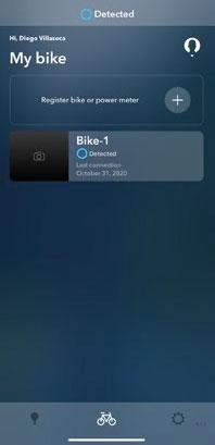
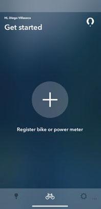
sie genau die zu deinem Fahrstil passende Leistung bietet. Zudem erlaubt der EP8-Motor die Auswahl von zwei unter-
Leistung des Kemen genau auf deine Bedürfnisse einzustellen.
gem Handbuch zur Etube Project Cyclist App für Smartunter anderem auch die Belegung des Unterstützungsstufenschalters anpassen, Fehlercodes einsehen oder die
Lade die App über Google Play oder den Apple Store herunter und installiere sie auf deinem Smartphone.
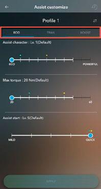
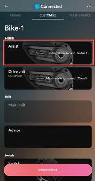

1.Starte die Etube-Project-App auf deinem Smartphone.
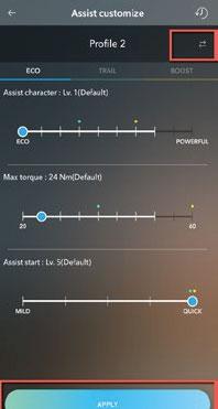
Schalte dein Fahrrad ein und öffne die App auf deinem Smartphone.
2.Wähle „Fahrrad oder Leistungsmesser registrieren“.
3.Wähle das zu verbindende Fahrrad.
4.Registriere dein Fahrrad in Etube Project.
nächsten Schritt weiter.
5.Wähle im Menü „Einstellen“ den Punkt „Unterstützen“.
6.Passe das maximale Drehmoment und die Unterstützungscharakteristik für jede Unterstützungsstu-
ne Fahrten nutzen möchtest.„Anwenden“ zu speichern.
BLUE PAPER KEMEN 2022 30 | ORBEA ORBEA | 31 2 3 5 6 4 7 TECHNISCHES HANDBUCH DE
-
-
-
-
07 SHIMANO ETUBE PROJECT CYCLIST
-
Nach dem Trennen der Verbindung zur App ist der Verbindungsunterbrechung auf dem Bildschirm der App zu sehen war.
Bei Modellen, die mit dem Display SC-EM800 von -
gesehen von der Verwendung der App Etube Project Cyclist, wie oben beschrieben).
·Bildschirm Einstellungsmenü (halte die Displaytas-
Anleitung zum Display SC-EM800 von Shimano:
um/7H90B/UM-7H90B-001-ENG.pdf
Anleitung zum Display SC-E5003 von Shimano:
08 ORBEA RS TOOLBOX
DATENFELD FÜR GARMIN GERÄTE
ORBEA RS TOOLBOX AUF GARMIN GERÄTEN INSTALLIEREN UND ENTSPERREN.
GARMIN EXPRESS (PC/MAC)

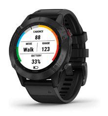
Orbea RS Toolbox ist ein Datenfeld für Garmin Geräte, das
um/7HU0B/UM-7HU0B-000-ENG.pdf
ANZEIGE VON SYSTEMFEHLERN
die Fehlercodes sowie Hinweise zum Prüfen und Beheben des Fehlers über die App Etube Project Cyclist abrufen.
Die einzelnen Unterstützungsstufen innerhalb
Mit dem Shimano Display SC-E5003 aus-
Project Cyclist verbunden werden, um das
über das Display SC-E5003 ausgewählt werden. Wenn du ein anderes Unterstützungs-
fen verändern möchtest, bringe dein Fahrrad -
le. Dort wird es über das Interface SM-PCE02 mit dem Tool Etube Project Professional verbunden, um die notwendigen Änderungen -
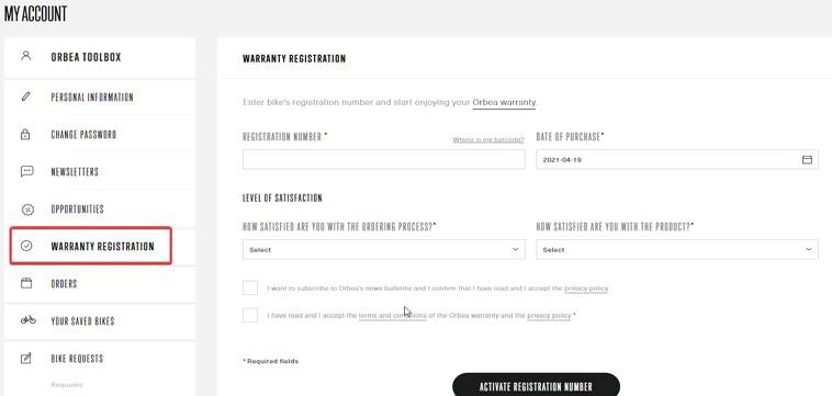
display durch das Display SC-EM800 von Shimano ersetzt werden.
Die Bedienungsanleitungen zu den Shimano Displays SC-
Lies den Abschnitt „Systemwarnungen/-fehler“ im Kapitel zur Nutzung des Kemen in diesem Handbuch, um zu erfahren, wie das System auftretende Fehler und Warnungen anzeigt. In diesem Zusammenhang werden die verschiedenen Fehlercodes und die Vorgehensweise zur Fehlerbehebung beschrieben.
Informationen zu deinem Kemen während der Fahrt im Auge behalten.
Modelle mit dem SC-E5003 von Shimano, -
nen nicht mit Garmin Geräten verbunden werden, auf denen das Datenfeld Orbea RS Toolbox installiert wurde.
Zur Verbindung dieser Modelle mit Garmin Geräten muss das Display SC-5003 durch das Display SC-EM800 von Shimano ersetzt werden. Zum Entsperren und Herunterladen
Geräte muss das Programm Garmin Express für PC/Mac verwendet werden. Die Vorgehensweise ist nachfolgend beschrieben.
ES IST NICHT MÖGLICH, ORBEA RS TOOLBOX MIT DER SMARTPHONE-APP GARMIN CONNECT ZU ENTSPERREN UND HERUNTERZULADEN
Lade Garmin Express für PC oder Mac herunter und installiere die Anwendung:
www.garmin.com/en-US/software/express/windows/
verfügen, damit die Anwendung entsperrt und herunter-
Um Orbea RS Toolbox auf deinem Garmin Gerät zu entsperren, musst du die Rahmennummer deines neuen Fahrrads auf der Orbea
du gleichzeitig in den Genuss der lebenslangen Orbea Garantie. Besuche die Orbea Website und registriere deine Rahmennummer.
www.orbea.com/de-de/access-register
BLUE PAPER KEMEN 2022 32 | ORBEA ORBEA | 33 TECHNISCHES HANDBUCH DE
-
4. Wähle „Anwendungen“.
6. Im Internetbrowser wird Garmin Connect IQ geöffnet.


Suche in Connect IQ nach der App Orbea RS Toolbox und wähle sie aus.
Falls du die App Orbea RS Toolbox nicht imnuierlich daran, die App für weitere Geräte zugänglich zu machen. Melde dich bei Orbea, falls du weitere Informationen hierzu benötigst.

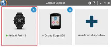
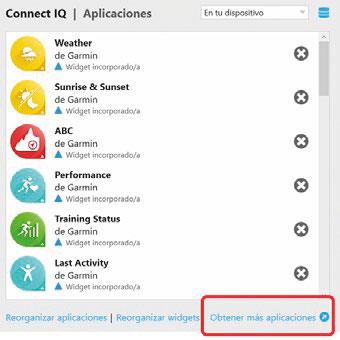
7. Wähle Orbea RS Toolbox „entsperren“.

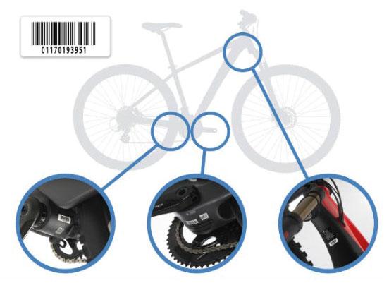
8. werden und dein Gerät zu entsperren.
5. Wähle „Weitere Apps herunterladen“.
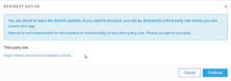
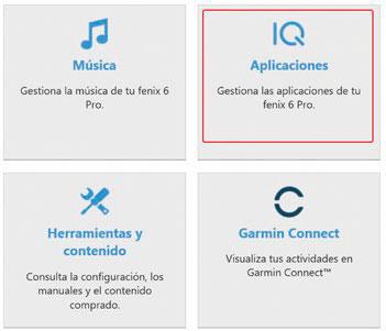
9. Gib auf der Orbea Website die Anmeldedaten für dein

10. Wenn du in der Vergangenheit bereits ein mit dem EP8 ausgestattetes Orbea Fahrrad über dein Konto registriert hast, wird dir die Website mitteilen, dass dein Gerät erfolgreich entsperrt wurde.
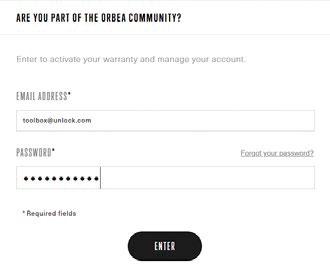
BLUE PAPER KEMEN 2022 34 | ORBEA ORBEA | 35 7 6 8 9 10 TECHNISCHES HANDBUCH DE
1. Schließe dein Garmin Gerät über das im Lieferumfang enthaltene Kabel an deinen PC oder Mac an.
2. Führe Garmin Express auf deinem Computer aus.
3.Wähle das Gerät aus, auf dem Orbea RS Toolbox installiert werden soll.
11.
im Garmin Connect IQ Store.

12. Auf der Orbea RS Toolbox-Seite in Connect IQ siehst ist. Orbea RS Toolbox wurde entsperrt. deinem Gerät zu installieren.
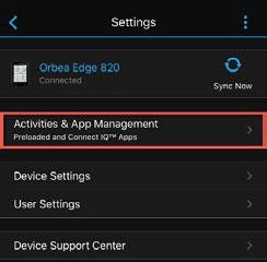
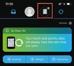
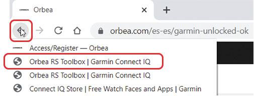
gezeigt wird, wurde Orbea RS Toolbox nicht entversuche erneut, die App zu entsperren.
13. Eine Meldung informiert dich darüber, dass Orbea RS Toolbox erfolgreich heruntergeladen wurde und dass die App bei der nächsten Synchronisierung deines Geräts installiert wird.
14. Beende den Internetbrowser und öffne Garmin Express. Dein Gerät sollte automatisch synchronisiert werden. Falls nicht, synchronisiere dein Gerät, bevor du es von deinem Computer trennst.
Trenne dein Gerät vom Computer.
Wenn du die Garmin Connect App aus Google Play oder dem Apple Store heruntergeladen und auf deinem SmartAktivitäten, Apps & mehr > Datenfelder
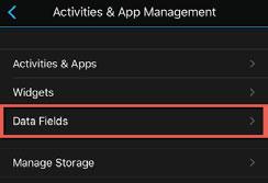
Synchronisiere dein Gerät, falls die App sichtbar, aber nicht installiert ist.
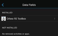

Im nächsten Abschnitt erfährst du, wie du Orbea RS Tool-
ORBEA RS TOOLBOX DATENFELD
AUF DEINEM GERÄT ANZEIGEN
Nachdem du die Orbea Toolbox App über Garmin Express (PC oder Mac) entsperrt und heruntergeladen und dein
Im Folgenden zeigen wir dir den Vorgang zur Anzeige des Toolbox Datenfelds für kompatible Garmin Uhren und Edge Geräte.
Orbea RS Toolbox ist nicht mit dem gleichzeitigen Einsatz der nativen Garmin Edge Shimano STEPS App auf den Geräten Edge 530, 830, 1030 und 1030 Plus kompatibel. das Fahrrad aus der Übersicht der verbundenen Sensoren deines Garmin Gerätes, bevor du Orbea RS Toolbox nutzt. Diese Ein-
geht von Garmin aus.
BLUE PAPER KEMEN 2022 36 | ORBEA ORBEA | 37 11 12 13 14 TECHNISCHES HANDBUCH DE
-
1. -
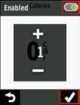

rät, auf dem du die Daten deines Fahrrads anzeigen möchtest. Sie verbinden sich automatisch.
du auf die Fahrraddaten zugreifen möchtest.
4. Wähle aus, welche Informationen du in dem Datenfeld
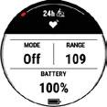


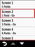


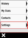

Solltest du das Kemen vor der Auswahl der Anzeige des Datenfelds nicht verbunden haben, zeigt das Gerät nach der Auswahl des Datenfelds Orbea RS Toolbox die Nachricht „Suche…“. Wenn du das Fahrrad einausgewählte Seite zugreifst, siehst du die Daten des Kemen.
Wenn nach Auswahl von Orbea RS Toolbox auf dem Bildschirm die Meldung „In Connect IQ entsperren“ erscheint, wurde die herun-
Schließe dein Gerät an den Computer an und starte erneut den Entsperr- und Downloadvorgang über Garmin Express. Beachte dazu die Beschreibung im voranstehenden Abschnitt.
auf welcher du die Daten deines Kemen sehen möch-
lung eines einzigen Datenfeldes.

bis zu der Seite, welche du für die Anzeige von Orbea RS Toolbox ausgewählt hast, um auf die Informationen deines Fahrrads zuzugreifen.
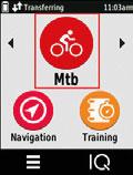
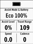

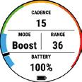
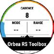
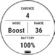
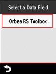
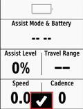
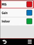
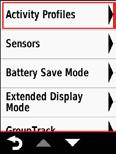

BLUE PAPER KEMEN 2022 38 | ORBEA ORBEA | 39 TECHNISCHES HANDBUCH DE
2.
Garmin Edge Geräte
Garmin Uhren
3.
-
Garmin Edge Geräte
Garmin Uhren
Garmin Edge Geräte
Garmin Uhren
5. -
Garmin Edge Geräte
Garmin Uhren
ORBEA RS TOOLBOX VERWENDEN
Orbea RS Toolbox ist nicht mit dem gleichzeitigen Einsatz der nativen Garmin Edge Shimano STEPS App auf den Geräten Edge 530, 830, 1030 und 1030 Plus kompatibel.
Übersicht der verbundenen Sensoren deines Garmin Gerätes, bevor du Orbea RS Toolboxbox, sondern geht von Garmin aus.
VERBINDE DEIN FAHRRAD MIT ORBEA RS TOOLBOX
Starte immer zuerst dein Garmin Gerät und beginne mit der
Anfang an in Toolbox angezeigt wird. Andernfalls wird der La-

Die Verbindung zwischen dem Fahrrad und Orbea RS Toolbox wird automatisch per ANT Private hergestellt. Sollten die Daten des Fahrrads nicht auf dem entsprechenden Datenfeld deines Garmin Geräts angezeigt werden, betätige die Tasten zum Wechsel der Unterstützungsstufe. Sollten die Daten nach wie vor nicht sichtbar sein, schalte das Fahrrad aus und wieder ein, um die Verbindung wiederherzustellen.
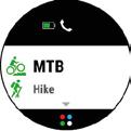
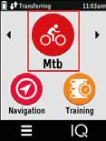
box wie jedes andere Datenfeld auf deinem Garmin Gerät verwendest, zugänglich.
ANGEZEIGTE DATEN DES KEMEN IN ORBEA RS TOOLBOX
UNTERSTÜTZUNGSSTUFE:
der vier verfügbaren Stufen Off, Eco, Trail und Boost an.
Beim ersten Start von Toolbox verbindet es sich mit dem fest mit diesem Fahrrad verbunden. Solltest du Probleme mit der Verbindung haben, stelle sicher, dass dein Fahrrad Herstellung der Verbindung zu vereinfachen.
· Anzeigeoptionen der Unterstützungsstufe (auf Garmin Uhren): Orbea RS Toolbox bietet zwei Varianten zur Anzeige der Unterstützungsstufe an. Im Abschnitt Anpassen der Datenfelder erfährst du, wie du einzelnen Datenfeldern die gewünschte Information zuweisenzungsstufe in einem Datenfeld auf dem Bildschirm anzeigen lassen.
nicht in der App Orbea RS Toolbox angezeigt werden, werden diese Daten wieder angediesem Moment meldet das EP8-System den Garmin Gerät, auf welchem er dann wieder angezeigt wird.
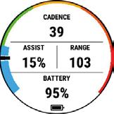

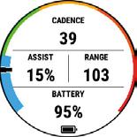

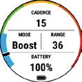
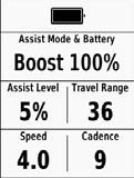
UNTERSTÜTZUNGSLEISTUNG: Anzeige der Unterstützungsleistung des Motors entsprechend der gewählten Unterstützungsstufe. Angezeigt als prozentuale Darstellung der Gesamtleistung des Motors.
· Anzeigeoptionen der Unterstützungsleistung (auf Garmin Uhren): Orbea RS Toolbox bietet zwei Varianten zur Anzeige der Unterstützungsleistung an. Im Abschnitt Anpassen der Datenfelder erfährst du, wie du einzelnen Datenfeldern die gewünschte Information
über den äußeren Ring der Toolbox anzeigen lassen. Die ausgewählte Unterstützungsstufe wird dabei entsprechend hervorgehoben. Und zwar in folgenden
den äußeren Ring der Toolbox anzeigen lassen. Dabei wird die Unterstützungsleistung in Form eines schwarzen -
erlauben die verschiedenen Unterstützungsstufen Zugriff auf voreingestellte Bereiche der Motorleistung. So erreicht zum Beispiel nur die höchste Unterstützungsstufe
Datenfeld „Assist“ angezeigt werden. Dabei wird dietion zur Gesamtleistung des Motors angezeigt.
REICHWEITE: Verbleibende Reichweite (in Kilometer oder -
aufgebrachter Pedalierleistung des Fahrenden unter Be-
GESCHWINDIGKEIT: Fahrrads.
KADENZ: Trittfrequenz auf dem Fahrrad.
BLUE PAPER KEMEN 2022 40 | ORBEA ORBEA | 41 TECHNISCHES HANDBUCH DE
-
-
-
Eco. Trail. Boost. Walk Assist Walk Assist Active Eco Trail Boost AKKU:-
1%-20% 21%-40% 41%-60% 61%-80% 81%-100% Unterstützungsleistung
Active Eco
Walk Assist Walk Assist
Trail Boost
ANPASSEN DER DATENFELDER
Die Reihenfolge, in welcher die Systemdaten auf dem ToolSmartphone-App Garmin Connect anpassen.
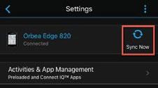
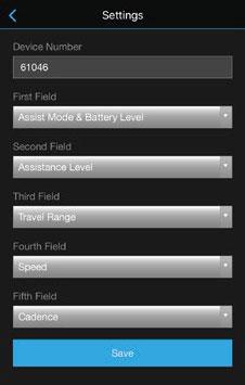
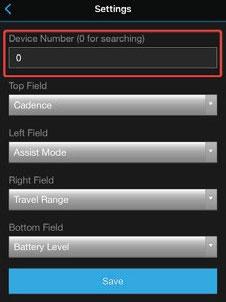
1. Öffne Garmin Connect auf deinem Smartphone und verbinde dein Garmin Gerät.
2. Greife über die App auf dein Gerät zu und wähle im App-Verwaltung > Datenfelder > Orbea RS Toolbox > Einstellungen
3. in den Datenfeldern von Orbea Toolbox angezeigt be-
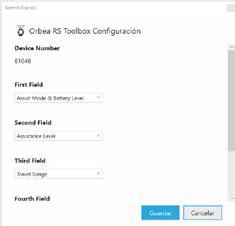
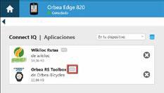
Ist das Gerät mit dem Fahrrad verbunden, während du die Änderungen speicherst, siehst du die neuen Einstellungen sofort.
GARMIN EXPRESS (PC UND MAC)
Express App auf deinem PC oder Mac anpassen. Verbinde dein Gerät über das Kabel mit deinem Computer und gehepassung der Orbea RS Toolbox und entscheide, welche Datenchere die Änderungen und synchronisiere das Gerät.
3. Schreibe „0“ (null) in das Feld „Gerätenummer“ und speichere die Änderungen.
4.chronisiere das Gerät.
5. Gehe wie in obigem Abschnitt beschrieben vor, um die Verbindung zu einem anderen Fahrrad herzustellen.
Vorgehensweise zu wiederholen. Falls die Verbindungsdeinstalliere Toolbox von deinem Gerät. Führe die Neuinstallation dann über die App Garmin Connect durch und versuche erneut, die Verbindung zum neuen Fahrrad herzustellen. Gegebenenfalls muss das Datenfeld auf deinem Gerät erneut ausgewählt werden.
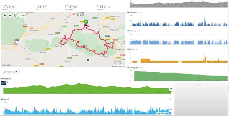
AKTIVITÄTSDATEN DES KEMEN ÜBER
GARMIN CONNECT AUFZEICHNEN
werden die Daten der Toolbox zusammen mit den weiteInformationen zu Unterstützungsstufe, Reichweite, Lade-
rufst du genauso über Garmin Connect ab wie die übrigen über dein Garmin Gerät aufgezeichneten Daten.
4. synchronisieren“. Wenn du jetzt dein Gerät mit deinem Fahrrad verbindest, werden die Daten entsprechend deiner gespeicherten Einstellungen angezeigt.
VERBINDUNG MIT EINEM WEITEREN FAHRRAD
Wenn Orbea RS Toolbox auf deinem Garmin Gerät installiert ist und darauf angezeigt wird, lässt sich eine Verbindung zu jedem anderen Orbea Fahrrad mit Shimano EP8
1. Öffne Garmin Connect auf deinem Smartphone und verbinde dein Gerät.
2. Greife über die App auf dein Gerät zu und navigiere zum
Aktivitäten, Apps & mehr > Datenfelder > Orbea RS Toolbox > Einstellungen
BLUE PAPER KEMEN 2022 42 | ORBEA ORBEA | 43 TECHNISCHES HANDBUCH DE
KEMEN MID
UND ERGONOMIE
GRÖSSESMLXL
1 - Sitzrohrlänge (C-T) 400453483533
2 - Oberrohrlänge (EFF) 563576606642
3 - Steuerrohrlänge 110115132153
4 - Kettenstrebenlänge 445445445445
5 - Tretlagerhöhe 307,5307,5307,5307,5
6 - Tretlagerabsenkung 63636363
7 - Radstand 1134114211731211
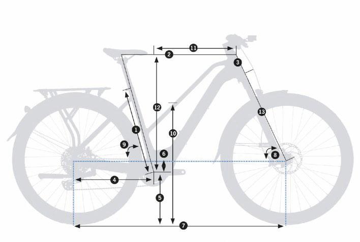
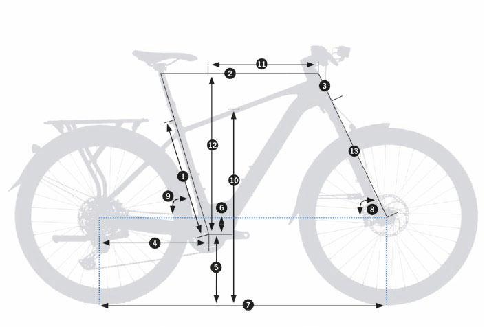
8 - Lenkwinkel 66,5º67º67º67º
9 - Sitzwinkel 75º75º75º75º
10 - Überstandshöhe 781810833866
10 - Überstandshöhe MID BAR 732740743-
11 - Reach 405415440470
12 - Stack 617624640659
13 - Gabellänge 513,5513,5513,5513,5
KÖRPERGRÖSSE(CM)KÖRPERGRÖSSE(IN)GRÖSSE*
155-17061.1”-66.9”S
165-18065.0”-70.9”M
175-19070.1”-74.8”L
185-20072.8”-78.74”
BLUE PAPER KEMEN 2022 44 | ORBEA ORBEA | 45 KEMEN
TECHNISCHES HANDBUCH DE
09
GEOMETRIE
* Die in der Tabelle genannten Maße sind Richtwerte. Wenn du sichergehen willst, welche Größe wirklich am besten zu dir passt, probiere das Fahrrad bei einer Orbea Verkaufsstelle aus.
MAXIMALE UND MINIMALE SITZHÖHE BEI VARIOSTÜTZEN
In der folgenden Tabelle werden die maximalen und minimalen Sitzhöhen bei der Verwendung einer Variostütze in ausgefahrenem Zustand für alle Rahmengrößen aufgeführt. Die maximale Sitzhöhe bezieht sich auf die Höhe des Sattels bei Montage der Sattelstütze bei entsprechend der durch die Sattelstütze vorgegebenen minimalen Einschubtiefe.
Die minimale Sitzhöhe bezieht sich auf die Höhe des Sattels bei Montage der Sattelstütze bei entsprechend der durch den Rahmen vorgegebenen maximalen Einschubtiefe. Aufgeführt werden nur die maximalen und minimalen Höhen für Kombinationen von Variostützen und Sättelnchenden Hersteller, um die jeweilige Höhe beim Einsatz einer anderen Variostütze zu erfahren. Die Angaben zur -
schnitt „Technische Daten“ in diesem Handbuch.
Die in der folgenden Tabelle aufgeführten Höhen beziehen sich auf den Abstand von der Mitte des Tretlagers bis zur Mitte der Satteloberseite (für von Orbea verbaute Sattelmo-
Höhe des Sattelmodells um +/- 5 mm abweichen. Sollte deine Sitzhöhe um weniger als 5 mm von den hier angegebenen Werten abwei-
schied gegebenenfalls ausgleichen.
Sollte deine Sitzhöhe um mehr als 5 mm von den hier angegebenen Werten abweichen, musst du eine Variostütze mit entsprechend höherem oder geringerem Hub wählen.
RAHMEN/GRÖSSE
* Die Werte können je nach Höhe des Sattelmodells um +/-5 mm abweichen.
BLUE PAPER KEMEN 2022 46 | ORBEA ORBEA | 47 MAX MIN TECHNISCHES HANDBUCH DE
VARIOSTÜTZE SITZHÖHENLIMIT KEMEN TOP (S) KEMEN TOP (M) KEMEN TOP (L) KEMEN TOP (XL) KEMEN MID (S) KEMEN MID (M) KEMEN MID (L) OC DP-MC20 31,6 50 mm Minimale Sitzhöhe. Ausgefahren 570 mm*619 mm*649 mm*701 mm*570 mm*619 mm*649 mm* Maximale Sitzhöhe. Ausgefahren 649 mm*699 mm*726 mm*780 mm*649 mm*699 mm*726 mm* OC DP-MC20 31,6 75 mm Minimale Sitzhöhe. Ausgefahren 594 mm*644 mm*674 mm*725 mm*594 mm*644 mm*674 mm* Maximale Sitzhöhe. Ausgefahren 669 mm*722 mm*752 mm*806 mm*669 mm*722 mm*752 mm* OC DP-MC20 31,6 100 mm Minimale Sitzhöhe. Ausgefahren 619 mm*670 mm*709 mm*751 mm*619 mm*670 mm*709 mm* Maximale Sitzhöhe. Ausgefahren 720 mm*773 mm*804 mm*854 mm*720 mm*773 mm*804 mm* OC DP-MC20 31,6 125 mm Minimale Sitzhöhe. Ausgefahren 657 mm*696 mm*724 mm*776 mm*657 mm*696 mm*724 mm* Maximale Sitzhöhe. Ausgefahren 770 mm*821 mm*852 mm*902 mm*770 mm*821 mm*852 mm* OC DP-MC20 31,6 150 mm Minimale Sitzhöhe. Ausgefahren 706 mm*719 mm*752 mm*800 mm*706 mm*719 mm*752 mm* Maximale Sitzhöhe. Ausgefahren 819 mm*873 mm*901 mm*952 mm*819 mm*873 mm*901 mm* OC DP-MC20 31,6 170 mm Minimale Sitzhöhe. Ausgefahren 746 mm*746 mm*770 mm*821 mm*746 mm*746 mm*770 mm* Maximale Sitzhöhe. Ausgefahren 858 mm*912 mm*945 mm*996 mm*858 mm*912 mm*945 mm*
10 TECHNISCHE DATEN
TECHNISCHE DATEN DES KEMEN
RAHMENMATERIAL
EMPFOHLENER EINSATZ ASTM Level 2. E-URBAN/ALL PURPOSE
GRÖSSEN
FEDERWEG DER GABEL 100 mm. Durch Schutzblech begrenzt. (120 mm ohne Schutzblech. Bei 120-mm-Gabel)
MAXIMALE LÄNGE DER GABEL (ACHSE ZU STEUERROHR) 515 mm. Durch Schutzblech begrenzt. (535 mm ohne Schutzblech)
GABEL-OFFSET 44 mm
STEUERSATZ Orbea ICR HS01. Interne Kabelführung
STEUERSATZLAGER Oben 1 1/2" (mit Adapter 1 1/2" auf 1 1/8" für interne Kabelführung) Unten 1 1/2"
MAX. STACKHÖHE STEUERSATZSPACER 20 mm
LENKER OC HB-MP31. Interne Kabelführung für STEPS und Licht-Fernbedienungsschalter
TRETLAGER Motor Shimano EP8 Achse
KETTENLINIE Boost. 53 mm
LAUFRADGRÖSSE 29"
Asphalt-Modelle: (Schutzbleche Apollo 65 mm) 29 x 2,2"
MAXIMALER EINSCHUB DER SATTELSTÜTZE
TOP BAR S 220 mm
TOP BAR M 270 mm
TOP BAR L 305 mm
TOP BAR XL 353 mm
MID BAR S 237 mm
MID BAR M 275 mm
MID BAR L 305 mm
VARIOSTÜTZE MIT INTERNER
KABELFÜHRUNG MÖGLICH Ja
UMWERFER Nein. Nur 1-fach
KOMPATIBLE KETTENBLÄTTER Mit Shimano EP8 Achsverzahnung. 11/12-fach. Kettenlinie 53 mm
MAXIMALE KETTENBLATTGRÖSSE 44Z
MINIMALE KETTENBLATTGRÖSSE 30Z
OVALE KETTENBLÄTTER MÖGLICH Nein
ART DER BREMSEN Scheibenbremse*/**
STANDARD DER BREMSAUFNAHME Post Mount
MAXIMALE GRÖSSE DER HINTEREN BREMSSCHEIBE 180 mm
MINDESTGRÖSSE DER HINTEREN BREMSSCHEIBE 160 mm
MAXIMALE GRÖSSE DER VORDEREN BREMSSCHEIBE
MINDESTGRÖSSE DER VORDEREN BREMSSCHEIBE
SUV-Modelle: (Schutzbleche Apollo 70 mm) 29 x 2,35"
MAXIMALE REIFENGRÖSSE
Ohne Schutzbleche
KETTENSCHUTZ MÖGLICH Keine Kettenführung bei Orbea Setups. Für Nachrüstoptionen wird ggf. ein Kettenblatt ohne Bashguard benötigt ICGS Nein
Hinterradbremse und Schaltwerk: Intern durch Steuersatz, Unterrohr und Kettenstreben. Durchgehende Außenhülle
E-Bike-System: Intern durch Steuersatz, Unterrohr und Kettenstreben.
KABELFÜHRUNG
MONTAGE DES MAGNETEN FÜR
GESCHWINDIGKEITSSENSOR** An der hinteren Bremsscheibe (siehe Abschnitt „Bestandteile des Motorsystems“)
STANDARD DER HINTERRADACHSE Boost 12 x 148
ABMESSUNGEN HINTERRADACHSE 12 x 180 mm
GEWINDESTEIGUNG HINTERRADACHSE 1,5 mm
GEWINDELÄNGE DER HINTERRADACHSE 14 mm
DURCHMESSER DER SATTELSTÜTZE 31,6 mm
DURCHMESSER DER SATTELKLEMME 34,9 mm
FLASCHENHALTER
Variostütze: Intern durch Steuersatz, Unterrohr und Sitzrohr. Durchgehende Außenhülle
Beleuchtung:
Mid Bar: 1. Alle Größen (Unterrohr). Range Extender Halter
Top Bar: 2. Alle Größen.
KOMPATIBLE SCHALTUNGEN MTB. 10-fach, 11-fach und 12-fach
BLUE PAPER KEMEN 2022 48 | ORBEA ORBEA | 49 TECHNISCHES HANDBUCH DE
TECHNISCHE DATEN DES KEMEN
SHIMANO DI2 MÖGLICH
SRAM AXS MÖGLICH
LEISTUNGSMESSER MÖGLICH Nein
Ja. Kompatibel zu herkömmlichen Gepäckträgern
TECHNISCHE DATEN
SHIMANO EP8
Herstellerhandbuch.
EP800/DM-EP800-03_ENG.pdf
GEPÄCKTRÄGERMONTAGE
Siehe Abschnitt über Gepäckträger in diesem Handbuch
Asphalt-Modelle: -
SUV-Modelle:seite der Ausfallenden.
STÄNDERMONTAGE Ja. Ursus Mooi
SCHUTZBLECHMONTAGE Kompatibel. Siehe Abschnitt über Schutzbleche
KINDERSITZMONTAGE
Siehe Abschnitt über Gepäckträger in diesem Handbuch
MAXIMALE ZULADUNG (Fahrer:in+Ausrüstung+Gepäck)
Asphalt-Modelle:
SUV-Modelle:
KOMPATIBILITÄT MIT FAHRRADANHÄNGERN Ja. Siehe Einzelheiten***
* Nicht alle auf dem Markt erhältlichen Bremssättel und Bremsscheiben sind mit allen Rahmen kompatibel. Sämtliche von Orbea aufgeführten Kombinationen wurden entsprechend getestet. Überprüfe vor dem Kauf von Zubehör die Abmessungen und Toleranzen.
** Orbea Setups sind mit Magura Scheibenbremsen ausgestattet. Der Bremsleitungswinkel an den Hebeln von Magura Bremsen sorgt für eine aufgeräumtere Optik, da die Leitungen besonders nah am Lenker verlaufen. Das Kemen ist auch mit anderen Scheibenbremshebel-Modellen kompatibel. Aufgrund der veränderten Leitungswinkel an den Hebeln ist die Kabelführung jedoch möglicherweise nicht ideal und die Leitungen sind stärker sichtbar.
· KOMPATIBILITÄT VON BREMSSCHEIBEN: Im Abschnitt „Bestandteile des Motorsystems“ erfährst du mehr zur Kompatibilität der hinteren Bremsscheibe.
*** KOMPATIBILITÄT MIT FAHRRADANHÄNGERN: Die folgende Tabelle zeigt, mit welchen Anhängermodellen zur Befestigung an der Hinterradachse der Rahmen kompatibel ist. Diese empfohlenen Modelle sind nicht von Orbea erhältlich, weshalb Orbea nicht für deren künftige Verfügbarkeit oder mögliche Inkompatibilität infolge von technischen Änderungen seitens der Hersteller haftet.
ANHÄNGERHERSTELLER ACHSMASSE ACHSENKENNUNG DES HERSTELLERS KOMPATIBLE ANHÄNGERMODELLE MONTAGEANLEITUNG
THULE M12 x 178 x 1,520110734
FOLLOW ME M12 x 178 x 1,5121125
BURLEY M12 x 178 x 1,5960121
CROOZER M12 x 178 x 1,5122500418
HAMAX 148 mm M12 x P1,5 mm936012
Namen der Komponente in das Suchfeld ein, um alle verfügbaren Handbücher und Informationen zu Ersatzteilen
Sämtliche Händlerhandbücher und Gebrauchsanweisungen von Shimano sind auf Si.Shimano abrufbar. Gib den
MOTOR SHIMANO EP8 RS
NENNLEISTUNG 250 W
SPANNUNG 36 V
TYP Bürstenloser Gleichstrom
MAXIMALES DREHMOMENT 85 Nm
HÖCHSTGESCHWINDIGKEIT 20 mph (US)
GEWICHT
UNTERSTÜTZUNGSPROFILE 2 (auswählbar über die App Etube Project oder das Display SC-EM800 von Shimano)
UNTERSTÜTZUNGSSTUFEN (JE PROFIL) 3 (ECO, TRAIL, BOOST), anpassbar über die Etube-Project-App SCHIEBEHILFE Ja
STANDARDVERKABELUNG MIT STEPS/DI2 EW-SD300
ANSCHLUSS VON BELEUCHTUNG Ja. 12 V DC. Nähere Informationen im Abschnitt „Beleuchtung“ in diesem Handbuch EINBAUWINKEL DES MOTORS 32º
DISPLAY SC-EM800 (AUSGEWÄHLTE MODELLE)
FUNKTIONEN
Anzeige des Ladestands
Anzeige der Unterstützungsstufe Fehleranzeige
Ein-/Ausschalten der Beleuchtung (siehe Abschnitt „Beleuchtung“)
KONNEKTIVITÄT
MONTAGE
STANDARDVERKABELUNG MIT STEPS/DI2 EW-SD300
HERSTELLERHANDBUCH
BLUE PAPER KEMEN 2022 50 | ORBEA ORBEA | 51 TECHNISCHES HANDBUCH DE
TECHNISCHE DATEN
SHIMANO EP8
DISPLAY/SCHALTEREINHEIT SC-E5003 (AUSGEWÄHLTE MODELLE)
Anzeige des Ladestands
Anzeige der Unterstützungsstufe
Fehleranzeige
INTEGRIERTER ORBEA RS AKKU 540 WH
SPANNUNG 36 V
KAPAZITÄT 540 Wh
GEWICHT
FUNKTIONEN
Auswahl der Unterstützungsstufe
Ein-/Ausschalten der Beleuchtung (siehe Abschnitt „Beleuchtung“)
ZELLEN Lithium-Ionen. Samsung 21700
LADEDAUER 100 % (4 A) Mit RS Smart Charger 4,5 Stunden
KONNEKTIVITÄT
MONTAGE
STANDARDVERKABELUNG MIT STEPS/DI2 EW-SD300 HERSTELLERHANDBUCH
UNTERSTÜTZUNGSSTUFENSCHALTER SW-EM800
Bei Modellen mit Display SC-EM800
FUNKTIONEN Auswahl der Unterstützungsstufe MONTAGE STANDARDVERKABELUNG MIT STEPS/DI2 EW-SD300
GESCHWINDIGKEITSSENSOR EW-SS301
MONTAGE
MAGNET Hintere Bremsscheibe (siehe Abschnitt „Bestandteile des Motorsystems“)
STANDARDVERKABELUNG MIT STEPS/DI2 EW-SD300
LADEDAUER 80 % (4 A) Mit RS Smart Charger 3 Stunden
MONTAGE
VERBINDUNG
WASSERDICHTIGKEIT IP66
ZERTIFIZIERUNGEN UN 38.3
KOMPATIBILITÄT Kompatibel mit Rise Hydro 2022 und Urrun 2022
EXTERNER AKKU RANGE EXTENDER RS 252 WH 2022
SPANNUNG
GEWICHT
ZELLEN Lithium-Ionen. Samsung 18650
LADEDAUER 100 % (2 A)
Mit RS Smart Charger 3,5 Stunden
MONTAGE Spezieller Halter. Unterrohr
VERBINDUNG
WASSERDICHTIGKEIT
ZERTIFIZIERUNGEN UN 38.3
KOMPATIBILITÄT
Kompatibel mit Rise Hydro 2022 (225-mm-Kabel), Kemen 2022 Top Bar (275-mm-Kabel) und Mid Bar (225-mm-Kabel) sowie Urrun 2022. Zur „Range Extender“ in diesem Handbuch.
BLUE PAPER KEMEN 2022 52 | ORBEA ORBEA | 53 TECHNISCHES HANDBUCH DE
36 V
KAPAZITÄT 252 Wh
TECHNISCHE DATEN SHIMANO EP8
SMART CHARGER ORBEA RS 2 A - 4 A
EINGANG 100 - 240 V. 50 - 60 Hz. AC
AUSGANG 42 V, 4 A DC
LADESTROM INTEGRIERTER AKKU RS 540 Wh 4 A
LADESTROM RANGE EXTENDER RS 252 Wh
2 A und passt den Ladestrom entsprechend an
TEMPERATURBEREICH ZUM AUFLADEN 0 ºC - 40 ºC
LADEPROZESSANZEIGE LED für Ladevorgang und Fehler
KOMPONENTEN, MONTAGE, NUTZUNG UND ERSATZTEILE 11 STEUERSATZ
ABMESSUNGEN DES STEUERROHRS
ZERTIFIZIERUNGEN
C-TICK AS/NZS CISPR 14.1
KOMPATIBILITÄT Kompatibel mit Rise Hydro 2022, Kemen 2022 und Urrun 2022
ORBEA RS VERKABELUNG
KABELBAUM RS 2022.
Anschluss an integrierten Akku-Motor-Ladebuchse -Einschaltknopf Kommunikationsprotokoll: Shimano STEPS
MINI-EINSCHALTKNOPF RS 2022Wasserdichtigkeit: IP66
KOMPATIBILITÄT Kompatibel mit Rise Hydro 2022, Kemen 2022 und Urrun 2022
DATEN ZUM STEUERSATZ HS01
BLUE PAPER KEMEN 2022 54 | ORBEA ORBEA | 55 ø56 7.5 3.85 ø56 ø52.1 ø52.1 45° TECHNISCHES HANDBUCH DE
TYPID*AD** Winkel des Rahmenlagers Zentrierrings / Gabelkonus SHIS CODE FSA Lager Artikelcode Lagerabmessungen OBEN 1 1/8" Integriert 1 1/2" Lager mit 1 1/8" ICR-Adapter 52,1 mm56 mm45º 45º IS52/40 TH-070E ACB Ç45° x 45° 1,5 dualS MR170 lager 52 x 40 x 7 mm UNTERSEITE 1 1/2" Integriert52,1 mm56 mm45º45ºIS52/40 TH-070E ACB Ç45° x 45° 1,5 dualS MR170lager 52 x 40 x 7 mm
AD:
* ID: Innendurchmesser des Steuerrohrs. **
Außendurchmesser des Steuerrohrs.
EXPLOSIONSZEICHNUNG UND MONTAGE DES STEUERSATZES
12 HINTERRADACHSE UND SCHALTAUGE
Informationen zur Kabelführung durch den Abschnitten „Kabelführung“ in diesem Handbuch.
Das von Orbea empfohlene Anzugsdrehmoment ist unbedingt zu beachten.
01ICR-STEUERSATZLAGER2022+GABELKONUS
021-1/8ICR-ZENTRIERRINGHS01MTB2022+SPACER
Der enthaltene Spacer wird beim Kemen nicht verwendet
ARTNº:XB08ANZAHL
2.11-1/8 ICR-Zentrierring 2022 MTB 1
2.2Spacer für ICR-Zentrierring 1
035-mm-SPACERICR-STEUERSATZDECKEL
ARTNº:XB24ANZAHL 1
05STEUERSATZSPACER-SETICR.RUND
ARTNº:X078ANZAHL
5.1ICR-Steuersatzspacer. Rund 10 mm2
5.2ICR-Steuersatzspacer. Rund 5 mm 2
04ICR-STEUERSATZDECKEL.DURCHM.56mmMITLICHT.
6-12VDCGOF2
ARTNº:X096ANZAHL
06SCHALTAUGENR.36X12MTBSTDM5X14
ARTNº:X757ANZAHL
6.1 1
6.2Schraube M5 x 14 DIN9121
KOMPATIBILITÄT MIT FAHRRADANHÄNGERN
07STECKACHSEBOOST12X148HOHL(12x180x1,5x14)
ARTNº:XB09ANZAHL x 1,5 x 14) 1
Die folgende Tabelle zeigt, mit welchen Anhängermodellen zur Befestigung
Diese empfohlenen Modelle sind nicht von Orbea erhältlich, weshalb Orbeage von technischen Änderungen seitens der Hersteller haftet.
ANHÄNGERHERSTELLER ACHSMASSE ACHSENKENNUNG DES HERSTELLERS KOMPATIBLE ANHÄNGERMODELLE MONTAGEANLEITUNG
THULE M12 x 178 x 1,520110734
FOLLOW ME M12 x 178 x 1,5121125
BURLEY M12 x 178 x 1,5960121
CROOZER M12 x 178 x 1,5122500418
HAMAX 148 mm M12 x P1,5 mm936012
BLUE PAPER KEMEN 2022 56 | ORBEA ORBEA | 57 1.1 2 3 4 5.1 5.2 GREASE 1.1 1.2 6 12 N.m 4 5 N.m GREASE 6.1 6.2 7 TECHNISCHES HANDBUCH DE
Gabelschaft
1.1Steuersatzlager 1,5 (52 x 40 x 7 mm. 45º/45º) 2 1.2 1
ARTNº:XA41ANZAHL
ICR Mit Licht. 6 - 12 V DC GOF2 1
PROTEKTOREN
14 KETTENBLATT
Das von Orbea empfohlene Anzugsdrehmoment ist unbedingt zu beachten.
08KETTENSTREBENSCHUTZKEMEN/URRUN22
ARTNº:XB10ANZAHL
8.1Kunststoff-Kettenstrebenschutz Kemen/Urrun 1
8.2Schraube M3 x 12 DIN79911
09MOTORSCHUTZEP800KEMEN/URRUN22
ARTNº:XB11ANZAHL
9.1Motorschutz Shimano EP8 Kemen/Urrun. Kunststoff 1
9.2Befestigungsschraube für Motorschutz3
Das Kemen ist mit Kettenblättern/Spidern mit Shimano EP8 Achsverzahnung und bis zu 44Z
Verwendung einer Kettenführung und eines Kettenblattschutzes für sicheren Kettenhalt. Bei Orbea Setups ist ein Kettenblatt mit inteauch ein Kettenblatt ohne Schutz verwendet
Abspringen der Kette verhindert. Orbea rät davon ab, andere Kettenblattgrößen als die
Motor von der Programmierung her optimal auf ein 36Z-Kettenblatt abgestimmt ist.
10KETTENBLATT36Z+SPIDER+SCHUTZPROWHEEL
NWS36A-S16-53.EP8
ARTNº:XB25ANZAHL
10.1Kettenblatt Stahl Prowheel NWS36T. 104BCD. Narrow-Wide 1
10.2Spider Prowheel S16-53 Shimano EP800. 104BCD. Boost 53 1
10.3Kettenblattschutz 36Z. 104BCD1
Das Kemen ist mit Kettenführungen mit Shimano
Falls eine Kettenführung angebracht ist, muss unterblatt ohne Schutz ausgetauscht werden. Dadurch wird verhindert, dass sich das Kettenblatt und die Kettenführung gegenseitig behindern.
Orbea rät davon ab, andere Kettenblattgrößen als die der Programmierung her optimal auf ein 36Z-Kettenblatt abgestimmt ist.
11KETTENBLATT-SICHERUNGSRINGFÜRSHIMANOEP8
ART.SHIMANOY78N00085ANZAHL
Kettenblatt-Sicherungsring für Shimano EP8 1
BLUE PAPER KEMEN 2022 58 | ORBEA ORBEA | 59 2 1.5 N.m 8.1 8.2 0.6 N.m 0.6 N.m 2 2 8.2 9.2 9.1 5 14 N.m 10 11 35-45 N.m Shimano TL-FC39 + TL-FC33 TECHNISCHES HANDBUCH DE
13
Das von Orbea empfohlene Anzugsdrehmoment ist unbedingt zu beachten.
15
SONSTIGE RAHMENTEILE
12SATTELSTÜTZENSCHELLE34,9mmSCHWARZ
Schraube enthalten
ARTNº:X202ANZAHL
Sattelstützenschelle 34,9 mm schwarz Schraube enthalten 1
13SCHRAUBEN-UNDUNTERLEGSCHEIBENKIT FLASCHENHALTERKEMEN/URRUN22
ARTNº:XB14ANZAHL
13.1Schraube M5 x 10 4
13.2Unterlegscheibe 5,5 x 10 x 24
Achte bei der Befestigung eines Flaschenhalters am Kemen darauf, dass die Schrauben des Flaschenhalters tief genug in die Löcher am Rahmen eingeschraubt sind.
Greift das Gewinde nicht tief genug, entferne die beiden ursprünglich vorgesehenen Unterlegscheiben, um eine sichere Montage zu gewährleisten und eine Beschädigung der Gewindebohrungen am Rahmen zu vermeiden.
14RAHMENANSCHLAG-CLIPBREMSLEITUNG
ARTNº:X502ANZAHL
Rahmenanschlag-Clip Bremsleitung 1
15FAHRRADSTÄNDERKEMEN/URRUN22
ARTNº:XB15ANZAHL
15.1Verstellbarer
BLUE PAPER KEMEN 2022 60 | ORBEA ORBEA | 61 GREASE 12 4 5 N.m GREASE 3 5 N.m 13.1 14 13.2 13.2 4 4 5 N.m 15.1 15.2 TECHNISCHES HANDBUCH DE
Das von Orbea empfohlene Anzugsdrehmoment ist unbedingt zu beachten.
16 FAHRRADSTÄNDER
Fahrradständer Ursus Mooi 1 15.2 2
Das von Orbea empfohlene Anzugsdrehmoment ist unbedingt zu beachten.
Das Kemen Mid besitzt nur Gewindeeinsätze für einen Flaschenhalter am Unterrohr.
17 VORBAU
VORBAU ORBEA URBAN ICR 35 mm
MATERIAL Aluminium
Ø LENKER (D1) 35 mm
Ø GABELSCHAFT (D2) 1 1/8"
INTEGRIERTE KABELFÜHRUNG (ICR)
SHIMANO STEPS Integrierte Kabelführung zum Shimano Display
COMPUTERHALTERUNG MÖGLICH An Vorbau-Frontplatte (Standard IFC01) statt Scheinwerfermontage
SCHEINWERFERADAPTER Ja. Siehe Abschnitt „Beleuchtung“
ERHÄLTLICHE LÄNGEN (L) 70 mm
WINKEL (A) -6º
STEUERSATZSPACER 5 mm und 10 mm. Orbea ICR rund
VORBAUKAPPE
MONTAGE UND ERSATZTEILE
VORBAU ORBEA URBAN ICR 35
Das Kemen 2022 ist nur mit dem Vorbau
dem ICR-Steuersatz für eine integrierte Ka-truiert, dass er die interne Kabelführung zum Steuersatz ermöglicht.
Nähere Informationen über die Kabelführung den Abschnitten „Kabelführung“ in diesem Handbuch.
16VORBAUORBEAURBANICR35.70mm
Vorbaukappe nicht enthalten
ARTNº:XB16ANZAHL
Vorbau Orbea Urban ICR 35. 70 mm 1
Das von Orbea empfohlene Anzugsdrehmoment ist unbedingt zu beachten.
17KLEINTEIL-KITVORBAUOCST-RP21
ARTNº:X069ANZAHL
17.3Schraube M5 x 15 DIN912. Gabelschaft und Vorbau-Frontplatte 6
17.4Schraube M3 x 10 DIN7991 (bei Vorbau Urban ICR 35 nicht verwendet) 2 17.5Orbea Frontplattenlogo1
18UNTEREABDECKUNGVORBAUURBANICR35.RUND
ARTNº:XB17ANZAHL
ICR 35. Rund 1
04ICR-STEUERSATZDECKEL.DURCHM.56mmMIT
LICHT.6-12VDCGOF2
ARTNº:X096ANZAHL
Mit
035-mm-SPACERICR-STEUERSATZDECKEL
ARTNº:XB24ANZAHL 1
05ICR-STEUERSATZSPACER-SETRUND
ARTNº:X078ANZAHL
5.1ICR-Steuersatzspacer. Rund 10 mm2
5.2ICR-Steuersatzspacer. Rund 5 mm 2
BLUE PAPER KEMEN 2022 62 | ORBEA ORBEA | 63 L A D1 D2 6 8 N.m 4 6 N.m GREASE 4 6 N.m GREASE GREASE 16 17.1 17.2 17.3 16.3 17.5 18 3 5.1 5.2 See Lights section 4 TECHNISCHES HANDBUCH DE
17.1 1 17.2 1
12 V DC GOF2 1
Licht. 6
KABELFÜHRUNG FÜR MECHANISCHE KOMPONENTEN
SCHALTWERK - HINTERRADBREMSE - REMOTE-SCHALTHEBEL DER VARIOSTÜTZE
19 MOTORSYSTEM
Für die Montage der Komponenten des Motorsystems werden fortgeschrittene Kenntnisse benötigt, übersteigen.
Wende dich zur Diagnose, Reparatur und Montage von Komponenten des Motorsystems des Urrun den Komponenten, die auf eine unsachgemäße
dass die Garantie für diese Komponenten erlischt.
ANSCHLUSSSCHEMA
DER KOMPONENTEN
Je nach gewähltem Shimano Display am Kemen (SC-EM800
Motor zu den Displays/Unterstützungsstufenschaltern.
dard EW-SD300 für Di2- und STEPS-Komponenten.
Bei Systemen mit dem Display SC-EM800 wird ein 1200
Motor und Display verwendet. Das Display wird über zwei EW-SD300 Kabel mit dem Unterstützungsstufenschalter am Display angeschlossen, das 300 mm lange am Schal-brachten EW-JC302 Verbindungsadapter verbunden.
Das Kemen besitzt einen OC HB-MP31 LenKabelführung zum STEPS-Schalter und zum Abschnitt „Beleuchtung“ in diesem Hand-rung verwendet werden. Bei Montage eines zum Display SC-E5003, zum UnterstützungsFrontscheinwerfers (optional) außen am LenMC31 in diesem Handbuch.
14RAHMENANSCHLAG-CLIPBREMSLEITUNG
ARTNº:X502ANZAHL
Rahmenanschlag-Clip Bremsleitung1
Bei Systemen mit dem Display SC-E5003 führt ein 1200 mm langes EW-SD300 Kabel vom Motor zu einem im Vorbau untergebrachten EW-JC302 Verbindungsadapter. Zwei EW-SD300 Kabel (400 mm und 300 mm), die durchbindungsadapter verbunden sind, verbinden das Display SC-E5003 mit dem JC302 Verbindungsadapter im Vorbau.
BLUE PAPER KEMEN 2022 64 | ORBEA ORBEA | 65 14 TECHNISCHES HANDBUCH DE
Das von Orbea empfohlene Anzugsdrehmoment ist unbedingt zu beachten.
Variostütze 18
Schalt-
Variostütze
Hinterradbremse
Hinterradbremse
-
ANSCHLUSSSCHEMA DER KOMPONENTEN
* Bei beiden Systemen, also entweder mit dem Display SC-EM800 oder dem Display
Kabel (400 mm und 300 mm) sowie der
Display mit dem Unterstützungsstufenschalter (SC-EM800 Systeme) bzw. der
(SC-E5003 Systeme) verbunden wird, durch ein 700 mm langes EW-SD300 Kabel ersetzt werden. Bei Orbea Systemen -
ZUGEHÖRIGE AUFLISTUNG DER SYSTEMBESTANDTEILE AM ENDE DIESES ABSCHNITTS
Siehe Kompatibilität der Bremsscheibe
BLUE PAPER KEMEN 2022 66 | ORBEA ORBEA | 67 7 8 4* 5* 3* EW-SD300 4* 5 5 EW-SD300 3* EW-SD300 EW-SD300 6 11 10 16 12 2 13 15 1 9 18 14 17 SC-EM800 SC-E5003 SW-EM800-L EW-JC302 EW-JC302 EW-JC302 EW-SD300 SW-EM800-L SC-EM800 SC-E5003 EW-JC302 EP8 MOTOR OR EW-JC302 EW-JC302 700 mm 300 mm 400 mm 700 mm 300 mm 400 mm EP8 MOTOR 1200 mm 1200 mm OR TECHNISCHES HANDBUCH DE Im Vorbau
Im Vorbau
KABELFÜHRUNG FÜR SHIMANO KOMPONENTEN
Für die Montage der Komponenten des Motorsystems werden fortgeschrittene Kenntnisse benötigt, welche dieKomponenten erlischt.
Display SC-EM800 von Shimano
Display/Schaltereinheit SC-E5003 von Shimano
BLUE PAPER KEMEN 2022 68 | ORBEA ORBEA | 69 TO EP8 MOTOR TO EP8 MOTOR SC-EM800 SW-EM800-L SC-E5003 18 400 mm 300 mm 1200 mm 400 mm 300 mm 1200 mm EW-JC302 EW-JC302 EW-JC302 1200 mm 0.6 N.m T10 3 2.5 N.m Magnet 6-BOLT 19 2.5 3 N.m 17 Magnet 9 2 5* 4* 7 3* 7 2 8 4* 3* 5* 5 2 TECHNISCHES HANDBUCH DE
Innen Innen Innen
AUFLISTUNG DER SYSTEMBESTANDTEILE AM ENDE DIESES ABSCHNITTS CENTERLOCK MAGURA (hinter Scheibe) Orbea Setups CENTERLOCK
Verschlussring NICHT KOMPATIBEL Siehe
ZUGEHÖRIGE
an
Kompatibilität der Bremsscheibe
KABELFÜHRUNG FÜR SHIMANO
KOMPONENTEN
ge EW-SD300 Kabel am neuen SC-EM800 Display an. Schließe auch das andere SW-SD300 Kabel, das du ge-
Display an.
Trenne das Kabel vom Display SC-E5003 und nimm dasfernt werden. Montiere den Unterstützungsstufenschalter zuvor mit dem Display SC-E5003 verbunden war. Das Sysdes Fahrrads.
INSTALLATION DES DISPLAYS SC-EM800
AUF MODELLEN MIT SC-E5003 BLUETOOTHUND ANT-PRIVATE-KONNEKTIVITÄT
Das Display SC-E5003 von Shimano unterstützt weder Bluetooth noch ANT Private. Da-
Modelle nicht mit der Shimano-App Etube Systems verbunden werden.
Garmin Geräten verbunden werden, auf denen das Datenfeld Orbea RS Toolbox installiert ist, um Daten des Fahrrads während der Fahrt anzuzeigen.
Um das Display SC-E5003 durch das Display SC-EM800 zu ersetzen, damit eine ANT-Private- und Bluetooth-Ver-
Komponenten von einem Shimano Vertriebshändler be-
·Display SC-EM800 von Shimano (Klemmendurchmesser 35 mm).
· Unterstützungsstufenschalter SW-EM800-L.
Der Vorbau muss vom Gabelschaft abmontiert werden,
BLUE PAPER KEMEN 2022 70 | ORBEA ORBEA | 71 SW-EM800-L SC-EM800 SC-E5003 EW-JC302 EP8 MOTOR OR EW-JC302 EW-JC302 700 mm 300 mm 400 mm 700 mm 300 mm 400 mm EP8 MOTOR 1200 mm 1200 mm OR TECHNISCHES HANDBUCH DE
-
-
-
Im Vorbau
KABELFÜHRUNG FÜR ORBEA RS KOMPONENTEN
Für die Montage der Komponenten des Motorsystems werden fortgeschrittene Kenntnisse benötigt, welche die
Komponenten erlischt.
ZUGEHÖRIGE AUFLISTUNG DER SYSTEMBESTANDTEILE AM ENDE DIESES ABSCHNITTS
BLUE PAPER KEMEN 2022 72 | ORBEA ORBEA | 73 12 13 14 15 TECHNISCHES HANDBUCH DE
-
Motor EinschaltIm Rahmen
VERBINDEN DES KABELBAUMS MIT DEM INTEGRIERTEN AKKU
Achte beim Verbinden des RS Kabelbaums mit dem inausgerichtet sind.
Wenn der Sicherungsring nach dem Loslassen nicht in seinicht gesichert.
sichert ist.
KABELFÜHRUNG IM RAHMEN. AUSBAU VON MOTORGEHÄUSE, KABELBAUM UND EINSCHALTKNOPF
(der mit einer Mutter auf der Innenseite des Rahmens befestigt ist) musst du den Motor vom Rahmen abnehmen.
du, wie du den Motor vom Rahmen demontierst, um auf
cherungsring am Kabel lösen. Für eine sichere Verbindung
BLUE PAPER KEMEN 2022 74 | ORBEA ORBEA | 75 TECHNISCHES HANDBUCH DE
-
-
Beleuchtung Variostütze Hinterradbremse
Display Motor
BESTANDTEILE DES MOTORSYSTEMS
ORBEA RS UND SHIMANO KOMPONENTEN
SHIMANOKOMPONENTEN*
1MOTOR SHIMANO EP8
ORBEARSKOMPONENTENARTNº
10 INTEGRIERTER AKKU ORBEA RS 540 Wh 36 V
KOMPATIBILITÄT VON
BREMSSCHEIBEN
2KABEL SHIMANO STEPS-DI2 EW-SD300 1200 mm
3KABEL SHIMANO STEPS-DI2 EW-SD300 400 mm
11 RS 252 Wh 36 V 2022 275-mm-Kabel Y041
Kemen grundsätzlich an der hinteren Bremsscheibe angebracht. Alle Original-Kemen-Modelle von Orbea ausgestattet. Der bei Orbea Setups verwendete Ge-
montiert. Bei den Magura MDR-C-CL Bremsscheiben
Bremsscheibe hervor. Daran wird der Orbea Magnet -
4KABEL SHIMANO STEPS-DI2 EW-SD300 300 mm
12 SMART CHARGER ORBEA RS 2 A - 4 A EU/US/UK/AUS
terradnabe gesetzt wird. Wenn Scheibenbremsen von Shimano montiert werden sollen, bieten die Brems-
scheiben SM-RT30 von Shimano eine entsprechende Bremsscheiben MDR-C CL von Magura und SM-RT30 von Shimano sind für die Verwendung mit dem Magohne integrierten Magneten verwendet werden sollen, ist es Aufgabe des Nutzers / der Nutzerin bzw. der Verüberprüfen.
5VERBINDUNGSADAPTER SHIMANO EW-JC302
13 LADEBUCHSENABDECKUNG mit Schrauben
14 KABELBAUM RS AKKU/ LADEBUCHSE/SCHALTER (205/150/80 mm)
CENTERLOCK-BREMSSCHEIBEN MIT MONTAGEFLÄCHE
FÜR DEN MAGNETEN XB18
KOMPATIBEL
6DISPLAY SHIMANO SC-EM800 35 mm
15 RS MINISCHALTER EINSCHALTKNOPF mit Befestigungsmutter
16
7 UNTERSTÜTZUNGSSTUFENSCHALTER SHIMANO SW-EM800-L. Kein Kabel
17
8DISPLAY SHIMANO SC-E5003 35 mm
GESCHWINDIGKEITSSENSORMAGNET ORBEA CENTERLOCK MAGURA (hinter Scheibe)
Das Kemen ist mit Bremsscheiben von Magura und Shi-rierten Magneten besitzen.
CENTERLOCK-BREMSSCHEIBEN OHNE MONTAGEFLÄCHE FÜR DEN MAGNETEN XB18 NICHT KOMPATIBEL
9 GESCHWINDIGKEITSSENSOR SHIMANO EWSS301. 760 mm Kabel. Mit Schrauben
* Die Shimano Komponenten sind über einen Shimano Händler erhältlich.
18
GESCHWINDIGKEITSSENSORMAGNET ORBEA 6-LOCH
19GESCHWINDIGKEITSSENSORMAGNET ORBEA CENTERLOCK SHIMANO (an Verschlussring) NICHT KOMPATIBEL
Das Kemen ist nicht mit dem Centerlock-Magneten X095 von Orbea kompatibel. Dieser Magnet
ßenseite der Bremsscheibe angebracht. Beim Kemen und beschädigt ihn. Schäden an Komponenten, diehen, fallen nicht unter die Garantieleistung.
6-LOCH LAUFRÄDER/BREMSSCHEIBEN: Wenn Laufräder mit 6-Loch-Aufnahme verwendet werden
ben montiert werden.
tegriert ist.
BLUE PAPER KEMEN 2022 76 | ORBEA ORBEA | 77 TECHNISCHES HANDBUCH DE
-
-
-
KOMPATIBILITÄTSTABELLE
FÜR BREMSSCHEIBENhältlichen Bremsscheibenoptionen und dient als allgemeine Orientierungshilfe. Nicht alle möglichen Optionen von Scheibenbremsen und Bremsscheiben verantwortlich wurden. Es ist Aufgabe des Nutzers / der Nutzerin bzw.
KOMPATIBLEOPTIONEN
BREMSSCHEIBEMAGNET
Orbea, Bremsscheiben und Scheibenbremsen desselben Herstellers zu verwenden. Im Falle anderer Kombinationen
Sicherstellung der Kompatibilität verantwortlich.
KOMPATIBLEOPTIONEN
BREMSSCHEIBEMAGNET
6-LOCH
MAGURA MDR-C CL
Zur Montage siehe Abschnitt
„Kabelführung für Shimano Komponenten“


ORBEA XB18
Zur Montage siehe Abschnitt „Kabelführung für Shimano Komponenten“
NACHRÜSTOPTIONEN
BREMSSCHEIBEMAGNET
6-LOCHORBEA X240
NICHTKOMPATIBLEOPTIONEN
LENKER OC MC31
verlegt werden.
BREITE
Di2-Bohrung D1
RÜCKSEITE
Di2-Bohrung Di2-Bohrung Di2-KanalDi2-Kanal
SHIMANO SM-RT30
Shimano Bremsen ORBEA XB18

Zur Montage siehe Abschnitt „Kabelführung für Shimano Komponenten“
BREMSSCHEIBEMAGNET NICHT KOMPATIBEL
SHIMANO Ohne integrierten Magneten
Modelle
TECHNISCHE DATEN OC HB-MC31 35 mm
MATERIAL Aluminum Al6069
EMPFOHLENER EINSATZ Urban / MTB. ASTM Level 5
GEWICHT 385 g
BREITE eine Breite von 780 mm.
RISE 20 mm
MAGURA MDR-P CL
Magura Bremsen
SHIMANO Ohne integrierten Magneten Mit integriertem Magneten
SHIMANO Mit integriertem Magneten Verschiedene Modelle. Shimano Bremsen
IN BREMSSCHEIBE INTEGRIERT
UPSWEEP 3º
BACKSWEEP 9º
DURCHMESSER VORBAU (D1) 35 mm
DURCHMESSER LENKERENDEN (D2) 22,2 mm
Di2/STEPS-KOMPATIBEL Ja. Interne Kabelführung.
Bohrung und Kanal an den Enden zum Austritt des Di2/STEPS-Kabels
BLUE PAPER KEMEN 2022 78 | ORBEA ORBEA | 79 RISE TECHNISCHES HANDBUCH DE
-
CENTERLOCK
ORBEA SETUPS
MAGURA 2701966
CENTERLOCK
-
UPSWEEP
UNTERSEITE BACKSWEEP D2
INTERNE KABELFÜHRUNG ZU BESTANDTEILEN DES MOTORSYSTEMS
SYSTEME MIT DISPLAY SC-EM800 VON SHIMANO
BELEUCHTUNG
ZUM MOTOR
Frontscheinwerfers bei mit dieser Option ausgestatteten Systemen.
SYSTEME MIT DISPLAY SC-E5003 VON SHIMANO
UNTERANSICHT
Orbea bietet je nach gewähltem Kemen Modell zwei Optionen für den Frontscheinwerfer (Lezyne Power STVZO PRO E115 oder Lezyne Super HB STVZO E1000). Der entsprechende Ausstattung beim Kauf des Fahrrads über MyO Lite als Option ausgewählt werden.
Alle Kemen Modelle sind mit einem in den Steuersatzde-
Je nach gewähltem Kemen Modell gibt es außerdem zwei
Informationen zum Ein- und Ausschalten des Frontscheinwerfers, zum Verhalten der „Nutzung des Kemen“ in diesem Handbuch.
19LENKEROCHB-MC31.35/780.RISE20
Kompatibel mit interner Di2-Kabelführung
ARTNº:XB19
Kompatibel mit interner Di2-Kabelführung
verfügen hingegen über ein am hinteren Schutzblech mon-
Falls andere als die von Orbea verbauten Lichter am Kemen montiert werden sollen, ist es Aufgabe des Nutzers / Komponenten zu überprüfen.
DATEN ZUR BELEUCHTUNG
BELEUCHTUNG VORNE
TAGFAHRLICHT VORNE. IN STEUERSATZDECKEL INTEGRIERT.
SPANNINGA GOF2
HERSTELLER SPANNINGA
MODELL GOF2 e-Front Light
LEUCHTKRAFT 60 Lumen
LICHTTYP LED
EINGANGSSPANNUNG 6 - 12 V DC
VERBINDUNGSKABEL ZUM
E-BIKE-SYSTEM
EIN/AUS
BLUE PAPER KEMEN 2022 80 | ORBEA ORBEA | 81 300 mm EW-SD300* EW-JC302* 1200 mm EW-SD300* 400 mm EW-SD300* 1200 mm EW-JC302* 400 mm 300 mm EW-JC302 EW-SD300* EW-SD300* EW-SD300* TECHNISCHES HANDBUCH DE
Frontscheinwerfers bei mit dieser Option ausgestatteten Systemen. ZUM MOTOR
UNTERANSICHT
DATEN ZUR BELEUCHTUNG
BELEUCHTUNG VORNE
FRONTSCHEINWERFER.
LEZYNE SUPER HB STVZO E1000
HERSTELLER LEZYNE
MODELL EBIKE SUPER HB STVZO E1000
LEUCHTKRAFT Fernlicht: 1000 Lumen.
Abblendlicht: 600 Lumen
LICHTTYP LED
GEHÄUSEMATERIAL CNC-gefrästes Aluminum
SICHERHEITSSTANDARD Kappt den oberen Teil des Lichtstrahls, damit andere
SCHUTZ Sicherheitstemperaturschutz. Reduziert automatisch die Leistung.
EINGANGSSPANNUNG 11 - 15 V
LEISTUNG Fernlicht: 16 W. Abblendlicht: 8,5 W
VERBINDUNGSKABEL ZUM E-BIKE-SYSTEM 50 cm
LENKERTASTER Ja. Enthalten. 30-cm-Kabel
EIN/AUS
* Das Modell und die technischen Daten dessprüchen und der Kauf von Ersatzteilen für den Frontscheinwerfer müssen über einen Lezyne Vertragshändler erfolgen.
FRONTSCHEINWERFER.
LEZYNE E-BIKE POWER STVZO PRO E115 SWITCH
HERSTELLER LEZYNE
MODELL E-BIKE POWER STVZO PRO E115 SWITCH
LEUCHTKRAFT
Fernlicht: Abblendlicht:
LICHTTYP LED
GEHÄUSEMATERIAL CNC-gefrästes Aluminum
SICHERHEITSSTANDARD Kappt den oberen Teil des Lichtstrahls, damit andere
SCHUTZ Sicherheitstemperaturschutz. Reduziert automatisch die Leistung.
EINGANGSSPANNUNG 6 - 12 V DC
LEISTUNG 6 W
VERBINDUNGSKABEL ZUM E-BIKE-SYSTEM 200-mm-Kabel
LENKERTASTER Ja. Enthalten. 75-cm-Kabel
EIN/AUS
* Das Modell und die technischen Daten dessprüchen und der Kauf von Ersatzteilen für den Frontscheinwerfer müssen über einen Lezyne Vertragshändler erfolgen.
BLUE PAPER KEMEN 2022 82 | ORBEA ORBEA | 83 TECHNISCHES HANDBUCH DE
DATEN ZUR BELEUCHTUNG RÜCKLICHTER
GEPÄCKTRÄGERLICHT (SUV-MODELLE).
LEZYNE E-BIKE REAR SUPER BRIGHT STVZO E12
HERSTELLER LEZYNE
MODELL E-BIKE REAR SUPER BRIGHT STVZO E12
LEUCHTKRAFT 12 Lumen
LICHTTYP 2 LEDs
MONTAGE
SICHERHEITSSTANDARD Kappt den oberen Teil des Lichtstrahls, damit andere
EINGANGSSPANNUNG 6 - 12 V DC
MAX. LEISTUNG 0,8 W
VERBINDUNGSKABEL ZUM E-BIKE-SYSTEM
EIN/AUS
135-cm-Kabel
SCHUTZBLECH-RÜCKLICHT (ASPHALT-MODELLE).
LEZYNE E-BIKE REAR FENDER STVZO
HERSTELLER LEZYNE
MODELL E-BIKE REAR FENDER STVZO
LEUCHTKRAFT 11 Lumen
LICHTTYP 2 LEDs
MONTAGE Hinteres Schutzblech
SICHERHEITSSTANDARD Kappt den oberen Teil des Lichtstrahls, damit andere
EINGANGSSPANNUNG 6 - 12 V DC
MAX. LEISTUNG 1,2 W
VERBINDUNGSKABEL ZUM E-BIKE-SYSTEM
EIN/AUS
WARNLICHT Bei plötzlicher Verzögerung wird das Licht heller. Warnlicht
ANLEITUNG stvzo-e12
* Das Modell und die technischen Daten desgung ändern.
sprüchen und der Kauf von Ersatzteilen für Vertragshändler erfolgen.
135-cm-Kabel
WARNLICHT Bei plötzlicher Verzögerung wird das Licht heller. Warnlicht.
ANLEITUNG
* Das Modell und die technischen Daten desgung ändern.
sprüchen und der Kauf von Ersatzteilen für Vertragshändler erfolgen.
BLUE PAPER KEMEN 2022 84 | ORBEA ORBEA | 85 TECHNISCHES HANDBUCH DE
-
-
MONTAGE EINES FRON TSCHEINWERFERS
RÜCKLICHTMONTAGE AN GEPÄCKTRÄGER
UND SCHUTZBLECH
LEZYNE E-BIKE REAR SUPER BRIGHT STVZO E12
SUV-Modelle
LEZYNE E-BIKE REAR FENDER STVZO Asphalt-Modelle
ZUGEHÖRIGE AUFLISTUNG
DER SYSTEMBESTANDTEILE AM ENDE DIESES ABSCHNITTS
MONTAGE DES IN DEN STEUERSATZDECKEL INTEGRIERTEN TAGFAHRLICHTS
Siehe hierzu die Montageanleitung für den GOF2 Steuerin diesem Handbuch.
ZUGEHÖRIGE AUFLISTUNG
DER SYSTEMBESTANDTEILE AM ENDE DIESES ABSCHNITTS
BLUE PAPER KEMEN 2022 86 | ORBEA ORBEA | 87 4 6 N.m GREASE 2 2 N.m 4 6 N.m GREASE 20.1 20.2 20.3 20.4/22.2 21 LEZYNE
LEZYNE
22.1 23.1 23.2 23.4 23.3 24 4 5 N.m 3 3 N.m 25.1 25.2 26.1 26.2 TECHNISCHES HANDBUCH DE
SUPER HB STVZO E1000
E-BIKE POWER STVZO PRO E115
VORBAU
AM
KABELFÜHRUNG UND ANSCHLUSS DER KOMPONENTEN
Die Montage der einzelnen Bestandteile derbeitsvorgang, der fortgeschrittene mechanische Kenntnisse voraussetzt. Gegebenenfalls
aus dem Rahmen ausgebaut werden, um an sämtliche Teile zu gelangen. Orbea empdes Motorsystems nur von einer autorisierten
Durch eine nicht fachgerechte Montage verursachte Schäden an den Systembestandteilen fallen nicht unter die Garantieleistung.
Lichtanschluss am GOF2 Steuersatz Siehe nächste
Kabelführung durch Steuersatz und Vorbau Lezyne Frontscheinwerfer
BLUE PAPER KEMEN 2022 88 | ORBEA ORBEA | 89 - + 21.1 / 24.1 21.2 / 24.2 27 27 28 25 26 27 27 27 21.1 / 24.1 21.2 / 24.2 4 4 TECHNISCHES HANDBUCH DE
E-BIKE REAR FENDER STVZO mit Kabel. Asphalt-Modelle
SUPER BRIGHT STVZO E12 mit Kabel. SUV-Modelle
UNTERANSICHT 1100 mm Fernbedienung Fernbedienung Schwarz-weißes Kabel Schwarzes Kabel 1100 mm
Seite
AUFLISTUNG DER SYSTEMBESTANDTEILE AM ENDE DIESES ABSCHNITTS
Lezyne Frontscheinwerfer GOF2 Steuersatzlicht
ZUGEHÖRIGE
KABELFÜHRUNG UND ANSCHLUSS DER KOMPONENTEN
Bei Orbea Setups werden die Kabel der Frontlichter (Lezyne Scheinwerfer und GOF2 Licht imgeführt. Die Plusleitungen beider Kabel und die Minusleitungen beider Kabel werden mit einem 1-mm-Crimpverbinder verbunden und dann an den Minus- bzw. Plusanschluss des Motors angeschlossen.niert geliefert (beide Kabel und der Crimpverbin-den). An der Plus- und Minusleitung des Lezyneder verwendet.
Zuerst wird ein 0,25-mm-Crimpverbinder an jeder Leitung (Minus und Plus) angebracht. Anschließend wird ein 1-mm-Crimpverbinder auf den 0,25-mm-Verbinder aufgesetzt.-
tungsanschluss des Motors angeschlossen werden, da die Anschlussschraube bedingt durch -
lichtleitungen nicht angemessen gesichert wer-
von Orbea verbaut wurden, ist der Nutzer / die -
BESTANDTEILE DER BELEUCHTUNGSANLAGE
20ADAPTERFÜRFRONTSCHEINWERFER.LANG VORBAUORBEAURBANICR35mm
ARTNº:XB20ANZAHL
20.1Frontscheinwerfer-Halterung für Vorbau
Urban ICR. GoPro. Lang 1
20.2Schraube M5 x 20 ISO7380 1
20.3Sicherungsmutter M5 DIN985 1
20.4Schraube M3 x 8 DIN7991 2
22SCHEINWERFERADAPTERFRONTPLATTEOCVORBAU
ARTNº:XB26ANZAHL
22.1Scheinwerferadapter Frontplatte OC Vorbau 1
22.2Schraube M3 x 8 DIN7991 1
24FRONTSCHEINWERFERLEZYNEPOWERSTVZOPROE115
200-mm-Kabel mit JST-Stecker (nur Orbea Setups) Lenkertaster enthalten
zum Lezyne Frontscheinwerfer
ARTNº:*NICHTALSNACHRÜSTOPTIONVONORBEAERHÄLTLICHANZAHL
21FRONTSCHEINWERFEREBIKESUPERHBSTVZOE1000
50-cm-Kabel mit JST-Stecker (nur Orbea Setups) Lenkertaster enthalten
ARTNº:*NICHTALSNACHRÜSTOPTIONVONORBEAERHÄLTLICHANZAHL
23SCHEINWERFERHALTERUNGFRONTPLATTELEZYNE PROE115
ARTNº:X113ANZAHL
23.1Scheinwerferhalterung E115 Frontplatte 1
23.2Schraube für Scheinwerfergehäuse 1
23.3Schraube M5 x 15 ISO7380 1
23.4Sicherungsmutter M5 DIN985 1
25LEZYNEE-BIKEREARSUPERBRIGHTSTVZOE12 Gepäckträger-Montage. SUV-Modelle Crimpverbinder enthalten
ARTNº:*NICHTALSNACHRÜSTOPTIONVONORBEAERHÄLTLICHANZAHL
1 25.2 2
25.3Crimpverbinder 0,25 mm 2
25.4Crimpverbinder 1 mm 2
26LEZYNEE-BIKEREARFENDERSTVZO
Schutzblech-Montage. Asphalt-Modelle Crimpverbinder enthalten
ARTNº:*NICHTALSNACHRÜSTOPTIONVONORBEAERHÄLTLICHANZAHL 26.1
26.3Crimpverbinder 0,25 mm 2
26.4Crimpverbinder 1 mm 2
28SPANNINGASTECKERSATZFÜRBLANKEKABEL
ARTNº:XB30ANZAHL 3
27FRONTLICHTKABEL.1100mmX2KEMEN
1x blank an JST (Lezyne Scheinwerfer)
1x blank an blank (GOF2)
Crimpverbinder an Motorende vorinstalliert
ARTNº:XB29
Crimpverbinder am Motorende vorinstalliert
04ICR-STEUERSATZDECKEL.DURCHM.56mm
MITLICHT.6-12VDCGOF2
ARTNº:X096ANZAHL mit Licht. 6 - 12 V DC GOF2 1
BLUE PAPER KEMEN 2022 90 | ORBEA ORBEA | 91 27 TECHNISCHES HANDBUCH DE
21.1 1 21.2 30-cm-Kabel 1
24.1 1 24.2 530-mm-Kabel 1
25.1
Motor - Motor +
1 mm Crimpanschluss 0,25 mm Crimpanschluss 1 mm Crimpanschluss
zum GOF2 Steuersatzlicht
1
1
26.2
MONTAGE DES EP8 MOTORS 29BEFESTIGUNGSKITMOTOREP8
INTEGRIERTER AKKU RS 540 WH
der Bestandteile des Motorsystems und der Lies zudem die Hinweise zum Ladevorgang, Einschalten und Überprüfen des Ladestands im Abschnitt „Nutzung des Kemen“ in diesem Handbuch. Im Abschnitt „Wichtige Informa-und den Range Extender.
TECHNISCHE DATEN DES INTEGRIERTEN AKKUS
SPANNUNG 36 V
KAPAZITÄT 540 Wh
GEWICHT
ZELLEN Lithium-Ionen. Samsung 21700
LADEDAUER 100 % (4 A) Mit RS Smart Charger 4,5 Stunden
LADEDAUER 80 % (4 A) Mit RS Smart Charger 3 Stunden
MONTAGE
VERBINDUNG
WASSERDICHTIGKEIT IP66
ZERTIFIZIERUNGEN
KOMPATIBILITÄT
UN 38.3
Kompatibel mit: Kemen 2022 Rise Hydro 2022
Urrun 2022
Nicht kompatibel mit: Rise Carbon 2021-2022
BLUE PAPER KEMEN 2022 92 | ORBEA ORBEA | 93 29.5 6 12 N.m 29.2 29.5 6 12 N.m 29.2 6 12 N.m 29.5 29.6 29.2 6 12 N.m 29.5 29.2 29.5 6 12 N.m 29.1 29.3 29.4 29.5 6 12 N.m 29.1 29.3 29.4 TECHNISCHES HANDBUCH DE
ARTNº:XA87ANZAHL 29.1Befestigungsschraube Motor EP8 M8 x 26 2 29.2Befestigungsschraube Motor EP8 8 x P1,25 4 29.3Vorderer Distanzring Motorbefestigung 8 x 22 x 12 2
10 x 12 29.5Unterlegscheibe 8 x 13 x 0,56 29.6Hinterer Distanzring Motorbefestigung 8 x 16 x 6,5 1 Innen.
Motor Innen.
Innen.
Motor
-
29.4O-Ring
Zwischen Rahmen und
Zwischen Rahmen und Motor
Zwischen Rahmen und
Das von Orbea empfohlene Anzugsdrehmoment ist unbedingt zu beachten.
MONTAGE DES INTEGRIERTEN AKKUS IM RAHMEN
Das von Orbea empfohlene Anzugsdrehmoment ist unbedingt zu beachten.
Verwende nur Originalschrauben von Orbea zur Befestigung des
AUSBAU DES INTEGRIERTEN RS AKKUS INFORMATIONEN FÜR ORBEA HÄNDLER:INNEN
Für die Montage der Komponenten des Motorsystems werden fortgeschrittene Kenntnisse benötigt, übersteigen.
Wende dich zur Diagnose, Reparatur und Montage von Komponenten des Motorsystems des Urrun
Schäden an den Komponenten, die auf eine un-
nen dazu führen, dass die Garantie für diese Komponenten erlischt.
ausbauen und/oder austauschen zu lassen. Hierbei müssen nämlich wichtige Bestandteile des Fahrrads und des Motorsystems aus- und entfernen wollen, um mit dem Fahrrad zu verreisen, bring das Fahrrad stets zu einer Orbeameiden und die ordnungsgemäße und sichere -
durch eine unsachgemäße Installation beschäeiner entsprechend höheren Gefahr von Unfäl-
Eine ausführliche Schritt-für-Schritt-Anleitung ist im Abschnitt „Ausbau des integrierten RS
30BEFESTIGUNGSKITINTEGRIERTERAKKURS540WH
Informationen zum Anschluss des Kabelbaums amrung für Bestandteile des Motorsystems“ sowie nach-
31BEFESTIGUNGSKITINTEGRIERTERAKKURS540WH
DIAGNOSE DES INTEGRIERTEN RS AKKUS MIT 540 Wh (Händlerinformationen)
nose über Etube Professional möglich. Bei einer Störung
sional, um auszuschließen, dass das Problem auf Shimano
Setze dich mit Shimano in Verbindung und lass dem Kun-mano dir mitteilt, dass das Problem mit dem integriertenfrage auf Kide an Orbea.
1. Entferne die rechte Kurbel nach der vom Hersteller empfohlenen Methode.
api/publish/storage/pdf/en/dm/EP800/DM-EP800-03_ ENG.pdf
2. Entferne den oberen Teil der Kettenführung, damit das -
3. Entferne den Kettenblatt-Sicherungsring durch Drehen im Uhrzeigersinn. Hinterrad und Kette müssen am Fahrrad montiert sein, damit du das Kettenblatt durch
Kettenblatt-Sicherungsrings und des Kettenblatts die
4. Nimm den Kettenführungshalter ab, damit du auf die mit Schritt 5).
BLUE PAPER KEMEN 2022 94 | ORBEA ORBEA | 95 4 5 N.m 30.1 30.1 30.2 30.2 4 5 N.m 31 TECHNISCHES HANDBUCH DE
ARTNº:XA88ANZAHL 30.1 M6 x 9 2 30.2Unterlegscheibe 6
11
0,5
2
x
x
mm
ARTNº:XA81ANZAHL 540 Wh 1
-
-
-
2.5 4 4 2 3 Shimano TL-FC39 + TL-FC33 5 + 1 Shimano TL-FC18
8. Entferne die oberen Motorbefestigungsbuchsen.
Beim Wiedereinbau der oberen Buchsen und desse geführt werden, damit der Motor richtig eingebaut
BLUE PAPER KEMEN 2022 96 | ORBEA ORBEA | 97 6 7 6 6 6 6 6 6 5 8 9 4 4 TECHNISCHES HANDBUCH DE
7 -
6. Nimm den Motor vorsichtig vom Rahmen ab, damit die Kabel beim Absetzen des Motors nicht beschädigt werden.
Benutze einen Kreuzschlitz-Schraubendreher, um die
Display
Kabelbaum
5. Entferne die Befestigungsschrauben des Motors zusammen mit den Unterlegscheiben sowie die Motorbefestigungsbuchse im unteren Bereich auf der Innenseite.
9.
-
legscheiben am Unterrohr.
chen ist.
11. ziehst.
RANGE EXTENDER RS 252 WH 2022
Durch Anschluss des Orbea RS Range Extender am Kemen lässt sich die Kapazität des Systems um zusätzliche 252 Wh erweitern, sodass in Kombination mit dem integrierten
Damit erhöht der Range Extender die Reichweite des -
gehinweise und Vorgaben zur Nutzung der Bein diesem Handbuch. Lies zudem die Hinweise zum Ladevorgang, Einschalten und Überprüfen des Ladestands im Abschnitt „Nutzung des Kemen“ in diesem Handbuch. Im Abschnitt -
Lade den Range Extender vor der erstmaligen Verwendung vollständig auf. Lade den Range Extender sofort nach Erhalt auf. Wenn du den Range Extender nicht benutzt, lade ihn alle 2-3 Monate auf mindestens 50 % seiner Kapazität auf.
Wenn der Range Extender am Kemen angeschlossen ist, versorgt ausschließlich der Range Extender den Motor mit Strom, bis seine Reserven erschöpft sind (siehe Abschnitt
Maximalstrom, mit dem der Range Extender nicht aus, um den Bedarf des Motors bei hoher Beanspruchung (z. B. bei Auswahl der Stufe Boost an steilen Hängen und mit lang-
In einer solchen Situation, in der der Strombedarf des Motors größer als der vom Range Extender lieferbare Strom ist, zeigt der Range Extender möglicherweise einen Spannungsoder Temperaturfehler an (siehe Fehlercodes des Range Extender in diesem Abschnitt).
Falls der Range Extender einen solchen Temperaturfehler anzeigt, warte, bis die Temperatur des Range Extender wieder im Betriebsbereich liegt. Starte das Fahrrad neu, damit das System den Akku erkennen kann.
WICHTIGER HINWEIS ZUR VERWENDUNG DES RANGE EXTENDER AKKUS BEIM
KEMEN:
EINBAU DES INTEGRIERTEN AKKUS
12. -
zen, führst du die für den Ausbau beschriebenen Schritte
Bezüglich der Kabelführung und Drehmomenteinstellung der einzelnen Komponenten nimm auf die jeweiligen Abschnitte dieses Handbuchs Bezug. Informationen zur
Shimano Kurbeln FC-EM600:
EP800/DM-EP800-03_ENG.pdf
Orbea rät davon ab, den Range Extender am Kemen in Verbindung mit der Unterstützungsstufe Boost zu verwenden.
Wenn du den Range Extender am Kemen anschließen und verwenden möchtest, dürfen die Parameter der Unterstützungsstufen des EP8 Motors nicht über die Shimano-App Etube Project Cyclist oder Etube Project Professional geändert werden.
Der Shimano EP8 Motor am Kemen ist so programmiert, dass er ein maximales Drehmoment von 85 Nm und eine Leistung von 500 W liefert (dies entspricht der Standard-
Wenn der Range Extender den Temperaturschutz aktiviert, schaltet das elektrische System automatisch auf den integrierten Akku um, um das System mit Strom zu versorgen. Der Motor liefert also weiterhin Unterstützung, vorausgesetzt, der integrierte Akku verfügt über eine entsprechende Restladung.
Die Unterstützungsstufen Eco und Trail des Shimano EP8 Motors am Kemen sind des Motors nicht den vom Range Extender bereitgestellten Strom übersteigt.
Unterstützungsstufen Eco und Trail nicht zu ändern, wenn du beabsichtigst, einen Range Extender am Kemen anzuschließen.
BLUE PAPER KEMEN 2022 98 | ORBEA ORBEA | 99 10 11 12 TECHNISCHES HANDBUCH DE
-
10.
EXTERNER AKKU RANGE EXTENDER RS
TECHNISCHE DATEN
SPANNUNG 36 V
KAPAZITÄT 252 Wh
GEWICHT
ZELLEN Lithium-Ionen. Samsung 18650
LADEDAUER 100 % (2 A)
Mit RS Smart Charger
MONTAGE
VERBINDUNG
WASSERDICHTIGKEIT
ZERTIFIZIERUNGEN
3,5 Stunden
Spezieller Halter. Unterrohr
Top Bar: 275-mm-Kabel. Mid Bar: 225-mm-Kabel
MONTAGE DES RANGE EXTENDER
Der Range Extender muss grundsätzlich am Unterrohr befestigt werden. Bringe den Range Extender nicht am Sitzrohr an.
Kompatibel mit: Kemen 2022
KOMPATIBILITÄT
Nicht kompatibel mit: Rise Carbon 2021-2022
Montiere den speziellen Halter des Range Extender am Unterrohr des Kemen. Ziehe die Befestigungsschrauben mit einem Drehmoment von 5 Nm an. Entferne vor der Montage des Range Extender Halters die am Rahmen vormontierten Unterlegscheiben. Überprüfe nach der Mon-
ihn mit dem Sicherungsgummi.
Wenn der Range Extender nicht eingesetzt ist, kannst du den Range Extender Flaschenhalter auch
BLUE PAPER KEMEN 2022 100 | ORBEA ORBEA | 101 TOPBARTOPBARMIDBAR 3 5 N.m x6 TECHNISCHES HANDBUCH DE
VERBINDEN DES RANGE EXTENDER MIT DEM KEMEN
Drehe die Sicherungslaschen am Range Extender Kabel
Schließe das Kabel an der Ladebuchse des Range Extender an. Öffne die Ladebuchse am Fahrrad und schließe das Kabel des Range Extender an.
Beim Kemen Top Bar wird der Range Extender mit dem 275-mm-Kabel angeschlossen.
Beim Kemen Mid Bar wird der Range Extender mit dem 225-mm-Kabel angeschlossen.
Fixiere das Kabel, indem du die Sicherungslaschen im Uhrzeigersinn drehst.
Wenn du die Kabelverbindung des Range Extender lösen
men möchtest, drehe zuerst die Sicherungslaschen des
Sollte das Fahrrad während des Anschließens des Range Extender an der Ladebuchse des Fahrrads eingeschaltet sein, schaltet sich das System ab und muss neu gestartet werden. Dieser Vorgang ist notwendig, damit das Sys-
FUNKTIONSWEISE DES RANGE EXTENDER
Der Range Extender versorgt den EP8 Motor unmittelbar mit Energie. Beim Einsatz des Kemen mit verbundenem Range Extender versorgt ausschließlich der Range Extender den Motor mit Strom, bis seine Reserven erschöpft sind.
ANZEIGE DES LADESTANDS
fügt über eine entsprechende Restladung.
Solltest du mit der App Orbea RS Toolbox -

die Aufzeichnung der Daten des Orbea Ke-tivität werden weiter aufgezeichnet, wenn du das Kemen wieder nutzt. Sobald du das Fahrrad einschaltest, ist der Range Extender einsatzbereit. Der Range Extender muss nicht extra gestartet werden.
Wird der Range Extender bei eingeschaltetem Fahrrad abgetrennt, schaltet sich das Fahrrad von selbst aus und muss wieder eingeschaltet werden. Das System wird dadurch
Kombinierter Ladestand:
Wenn der Range Extender mit dem Orbea Kemen verbunden ist (wenn das Orbea Kemen mit verbundenem Range Extender eingeschaltet wurde), berechnet das
liefert die Information über den Ladestand des Systems
AKKULADESTAND DES AKKUSLADESTAND DES SYSTEMS
Integrierter RS Akku (540 Wh) 50 % 396 Wh von 792 Wh Range Extender (252 Wh)
AKKULADESTAND DES AKKUSLADESTAND DES SYSTEMS
Integrierter RS Akku (540 Wh)
% 666 Wh von 792 Wh Range Extender (252 Wh)
Wenn der Range Extender mit dem Fahrrad verbunden -
tem über das Display, die Verbindungseinheit bzw. die RS Toolbox (abhängig von der jeweiligen Installation) nur
BLUE PAPER KEMEN 2022 102 | ORBEA ORBEA | 103 TECHNISCHES HANDBUCH DE
-
-
84
-
Ladestand nur Range Extender:
Im Abschnitt „Wichtige Informationen zuden Range Extender.
PRÜFEN DES AKKUZUSTANDS DES RANGE EXTENDER-
AUFLADEN DES RANGE EXTENDER. des Kemen“ in diesem Handbuch erfährst du, wie du dentet sich der RS Smart Charger ab, sobald
des Range Extender muss das Ladegerät zunächst vom Stromnetz getrennt werden.
Ladegerät zwischen Ladevorgängen nicht versorgt.
Unter normalen Bedingungen und bei Einhaltung der in diesem Handbuch beschriebenen Empfehlungen bezüg-
schaltet sich von selbst aus, wenn es eingeschaltet war) und schalte das Fahrrad dann mit angeschlossenem Range Extender ein. Die vier LEDs am Range Extenderstand angezeigt und die LEDs erlöschen.
FEHLERCODES DER RANGE EXTENDER LED
Wenn der Range Extender die Ladung nicht hält oder nicht lädt -
ter Fehler vor, zeigen die LEDs den Fehlercode an. Informationen zum Fehler und möglichen Abhilfemaßnahmen
von idealen Bedingungen ausgegangen. Unter anderem die Nutzung, Aufbewahrung und -
empfohlenen Ladestands und der wieder-
Wo in der folgenden Tabelle die Aufforde-Kann ein Fehler oder eine Störung des Range Extender anhand der folgenden Tabelle nicht selbst behoben werden, ist eine autorisierte wird bei Orbea eine Supportanfrage einreichen und den Nutzer bzw. die Nutzerin über den Vorgang informieren.
DRÜCKELED-CODEFEHLERABHILFEMASSNAHME
Spannungs- oder Temperaturfehler
Warte, bis die Temperatur im Nutzungsbereich liegt. Starte beheben lässt.
AKKUZUSTANDLADESTANDEINSATZBEREIT
Temperaturschutz Warte, bis die Temperatur im Nutzungsbereich liegt.
Kurzschluss oder Strom zu hoch Kabel und die Ladebuchse auf Schmutz, wenn sich das Problem nicht beheben lässt.
Spannung zu niedrig Charger auf.
BLUE PAPER KEMEN 2022 104 | ORBEA ORBEA | 105 75%-100% 50%-74% 25%-49% 1%-24% 75%-100% 50%-74% 25%-49% 1%-24% 0% TECHNISCHES HANDBUCH DE
-
ERSATZTEILE FÜR DEN RANGE EXTENDER
32RSRANGEEXTENDER252WH2022
33VERBINDUNGSKABELRANGEEXTENDER2022 ARTNº:XA86ANZAHL
SMART CHARGER RS 2 A - 4 A
34RANGEEXTENDERHALTER
ARTNº:X223ANZAHL
34.2Kunststoff-Unterrohrschützer6
34.3Sicherungsgummi 1
36FLASCHENHALTER-BEFESTIGUNGSSCHRAUBENRANGE EXTENDERRS
Beim Kemen wird nur eine Unterlegscheibe pro Schraube verwendet
ARTNº:XA80ANZAHL
36.1Schraube M5 x 102
36.2Unterlegscheibe 6,2 x 10 x 24
35KITSICHERUNGSGUMMISRANGEEXTENDER ARTNº:X224ANZAHL
40 x 3,54
ZERTIFIZIERUNGEN
BLUE PAPER KEMEN 2022 106 | ORBEA ORBEA | 107 32 33 34 35 36 TECHNISCHES HANDBUCH DE
alle für die Montage des Range 1
ARTNº:Y041ANZAHL Enthält
Halter1
· Range Extender
1
· Kunststoff-Unterrohrschützer6
· Sicherungsgummi1
Kemen Top Bar 275 mm Kemen Mid Bar: 225 mm 1
34.1Range Extender Halter1
Sicherungsgummi
DATEN DES SMART CHARGER RS 2 A - 4 A EINGANG 100 - 240 V. 50 - 60 HZ. AC AUSGANG 42 V, 4 A DC LADESTROM INTEGRIERTER AKKU RS 540 WH 4 A LADESTROM RANGE EXTENDER RS 252 WH 2 A LADEDAUER INTEGRIERTER AKKU 540 Wh (4 A) 4,5 Stunden LADEDAUER RANGE EXTENDER RS 252 Wh (2 A) 3,5 Stunden ist und passt den Ladestrom entsprechend an TEMPERATURBEREICH ZUM AUFLADEN 0 ºC - 40 ºC LADEPROZESSANZEIGE LED für Ladevorgang und Fehler
NETZSTECKDOSE EU, UK, US, AUS
TECHNISCHE
OPTIONEN
KOMPATIBILITÄT Kompatibel mit: Kemen 2022, Rise Hydro 2022, Urrun 2022 Nicht kompatibel mit: Rise Carbon 2021-2022
ADAPTIVER LADESTROM
252 Wh) und passt den Ladestrom entsprechend an. Der beträgt 2 A (100 - 240 V).


Netzkabeloptionen EU, US, UK, AUS
ARTNº:XA82ANZAHL
Smart Charger Orbea RS 4 A - 2 A, 42 V EU, US, UK, AUS1
MASSNAHMEN ZUR STÖRUNGSBESEITIGUNG
AM RS SMART CHARGER
LEDMÖGLICHER FEHLER (Maßnahmen in angegebener Reihenfolge ergreifen)
Schutz. Strom zu hoch
ABHILFEMASSNAHME
· Trenne das Ladegerät ab.
im Abschnitt „Nutzung des Kemen“ in diesem
sich der RS Smart Charger ab, sobald der Range Extender muss das Ladegerät zunächst vom Stromnetz getrennt werden. Durch Wie-
-
BEDEUTUNG DER SMART CHARGER-LED


LEDVERHALTEN STATUS angeschlossen, aber nicht mit dem
und Ausblenden der blauen LED

Dauerhaft blau leuchtende LED Ladevorgang abgeschlossen
Dauerhaft rot leuchtende LED Ladefehler. Siehe folgende Tabelle zur Störungsbeseitigung
· Wenn sich das Problem nicht beheben lässt, setze dich mit einer Schutz. Kurzschluss
· Trenne das Ladegerät ab.
· Wenn sich das Problem nicht beheben lässt, setze dich mit einer Schutz. Temperatur zu hoch
· Warte, bis die Temperatur des Ladegerätes innerhalb des empfohlenen Ladetemperaturbereichs liegt.
· Wenn sich das Problem nicht beheben lässt, setze dich mit einer
Schutz. Stand-by Zeitüberschreitung bei Anschlussdauer des Ladegeräts an den Schutz. Schutz. Spannung zu hoch
NUTZUNGSHINWEISE ZUM
RS SMART CHARGER
erfährst du mehr über den richtigen Gebrauch und die
· Die Batteriespannung ist zu hoch.
BLUE PAPER KEMEN 2022 108 | ORBEA ORBEA | 109 TECHNISCHES HANDBUCH DE
VERWENDUNG DES RS SMART CHARGER -
37SMARTCHARGERORBEARS4A-2A,42V
WICHTIGE INFORMATIONEN ZU DEN RS LITHIUM-IONEN-AKKUS
Lies zu deiner eigenen Sicherheit vor derge Extender das Handbuch zu den Orbea RSüber die Verwendung und Montage von RS -
buch aufgeführt sind. Halte dich stets an die folgenden Hinweise, um Verbrennungen oder andere Verletzungen durch austretende Flüszu vermeiden.
Die folgenden Informationen gelten sowohl für den integ-
SICHERHEITSHINWEISE UND WARNUNGEN
ZU DEN AKKUS
· Verwende ausschließlich das spezielle RS Ladegerät oder sonstigen gefährlichen Orten halten.
zeit von fünf Stunden plus weiteren zwei Stunden (3,5 Stunden + 2 Stunden für den Range Extender) vollständig aufgeladen sein, sollte er vom Ladegerät getrennt
· Kinder nicht unbeaufsichtigt lassen, um sicherzustellen,fahrenzone entfernen. Sämtliche Personen sofort aus der Gefahrenzone bringen und das Feuer mit reichlich
BEDINGUNGEN FÜR DIE AUFBEWAHRUNG DER
Verletzungen führen.
· Nutzung (Entladung) des Akkus ausschließlich in einem Temperaturbereich von: –10 °C - 40 °C.raturbereich von: 0 °C - 40 °C. Materialien aufgeladen werden.
er verfärbt oder verformt ist oder sonstige ungewöhn-
· Temperaturbereich für die Aufbewahrung: 0 °C35 °C. Vermeide hohe Temperaturunterschiede. Luftfeuchtigkeit 5 % - 65 %.
den soll, dass er als Gefahrgut betrachtet wird. Verwen-
gen und Transportunternehmen.
· Die Anschlüsse (+) und (-) sowie andere Anschlüsse nicht mit metallischen Gegenständen in Berührung
Kurzschlüssen, Überhitzungen, Verbrennungen und
· Das Ladegerät nicht anschließen oder abtrennen, wenn es feucht ist. Es besteht Stromschlaggefahr. Bei austretenoder großer Hitze aufbewahren (zum Beispiel im Inneren eines Autos). Halte ihn fern von Hitze und Flammen. Anund Verletzungen zu vermeiden.
stellen und das Handbuch zu Rate zu ziehen. Setze dich im Zweifelsfall mit Orbea oder einer autorisierten Ver-mitteln oder Scheuermittel reinigen. Verwende zur Reini-
längeren Zeitraum nicht genutzt, sollte er vor der Nutzung aufgeladen werden.
BEDINGUNGEN FÜR DIE NUTZUNG
UND DAS AUFLADEN DER AKKUS außerhalb dieses Temperaturbereichs.
BEDINGUNGEN FÜR DIE MONTAGE DES AKKUS ersten Nutzung sollte sichergestellt werden, dass der
oder entnommen wird.
ANLEITUNG FÜR DAS AUFLADEN UND SICHERHEITSHINWEISE in deinem Fahrrad verwendest.
degerät.
BLUE PAPER KEMEN 2022 110 | ORBEA ORBEA | 111 TECHNISCHES HANDBUCH DE
-
-
-
-
-
-
AKKUS
--
-
-
-
-
-
-
das Ladegerät mit der Ladebuchse verbindest oder davon trennst.
· Stelle sicher, dass die Ladebuchse des Fahrrads sowie das Ladegerät anschließt.
· Das Ladegerät nicht verwenden, wenn du eine Beschä-
Rauchmelder ausgestatteten Raum aufzuladen.
des Ladegeräts zu vermeiden, wird vom dauerhaften
RECYCLING
weltgerechten Recycling zugeführt werden. -
· Die Ladebuchse stets verschlossen halten, wenn der
· Keine metallischen Gegenstände mit der Ladebuchse
· Vermeide, dass das Ladegerät feucht wird und verwende es nicht, falls es feucht sein sollte. Nicht mit feuchten Händen anfassen, um einen Stromschlag zu vermeiden.
· Das Ladegerät nicht verwenden, wenn es von einemgeräts berühren, um einen Stromschlag zu vermeiden.dem Regen oder Wind aussetzen.
· Das Ladegerät nicht am Kabel halten oder das Kabelschädigungen am Kabel zu vermeiden.
· Während des Ladevorgangs nicht pedalieren oder den
· Den Range Extender stets entfernen, bevor das Fahrrad
· Nach der Nutzung des Fahrrads eine Stunde warten, be-
sourcen. Folge den in deiner Region geltenden RecycFahrrad-Shop.handelt.
GEWÄHRLEISTUNGSAUSSCHLUSS
rad nicht in Gebrauch ist.
Verschleiß und Abnutzungen durch den normalen Gebrauch und Alterung.
richtigen Aufbewahrung, Nutzung, Umgebung sowie und unbrauchbar werden.
zum Verlust der Garantie führen. Das gilt auch für das
· Lies den Abschnitt zum Thema Garantie in diesem Handbuch für weitere Informationen zur Garantie auf Orbea
VERBINDEN DES EP8 SYSTEMS MIT ETUBE PROFESSIONAL ÜBER DAS INTERFACE SM-PCE02 VON SHIMANO (HÄNDLERINFORMATIONEN)
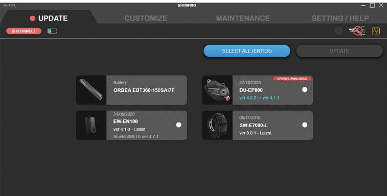
Die Systemdiagnose mit den Diagnosetools von Etube Professional muss von einer auto-
App Etube Project von Shimano zur Verbindung deines Fahrrads, zur Abstimmung des Systems auf deine Bedürfnisse sowie zu Dia-
teme mit dem Display SC-E5003 von Shima-
Etube Project Professional verbinden und die erforderlichen Änderungen am System vornehmen. Beispielsweise lassen sich Leistung
anpassen und ein anderes Unterstützungs-
programmiert, die weniger Unterstützung durch das System benötigen. Es wird folglich mehr Eigenleistung gefordert.
stützungsstufen nicht zu ändern, wenn du beabsichtigst, einen Range Extender am Kemen anzuschließen. Mehr dazu erfährst du im Abschnitt zum Range Extender in diesem Handbuch.
Damit du über Etube auf alle Informationen des Shimano -
dass es für jede Unterstützungsstufe die größtmögliche Unterstützung bietet.
BLUE PAPER KEMEN 2022 112 | ORBEA ORBEA | 113 TECHNISCHES HANDBUCH DE
-
-
Für die Verbindung des EP8 Systems mit Etube Professional wird das Interface SM-PCE02 von Shimano benötigt.
Systems mit der Vorrichtung SM-PCE02 verbunden und stop_the_project/toc_concept_s2q_vmh_tlb
INTERFACE SM-PCE1 VON SHIMANO. Das
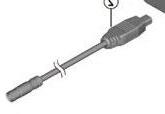
SM-PCE1 von Shimano mit Etube Professional verbunden werden.
Hierzu muss die Version 4 von Etube Professional verwendet werden. Etube V5 ist nicht


de Versionen von Etube Professional von der Shimano Website herunterladen.
ANSCHLUSS VON SYSTEMEN MIT DISPLAY SC-EM800
freien Anschlüsse am Display für das Interface SM-PCE02 genutzt werden.
Ein SD300-Kabel muss an diesen freien Anschluss angeschlossen werden. Verwende dann einen EW-AD305 Adapter für die Verbindung des SD300-Kabels mit dem PCE02 verwendet wird.
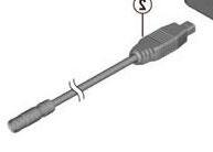
ten Verbindung von Display und SM-PCE02 verwendet werden.
ANSCHLUSS VON SYSTEMEN MIT DISPLAY SC-E5003
Bei Systemen mit dem Display SC-E5003, das nur einen SD300 Anschluss besitzt, muss ein EW-JC304 Verbindungsadapter von Shimano verwendet werden, damit ein freier Anschluss für die Verbindung des Systems mit dem
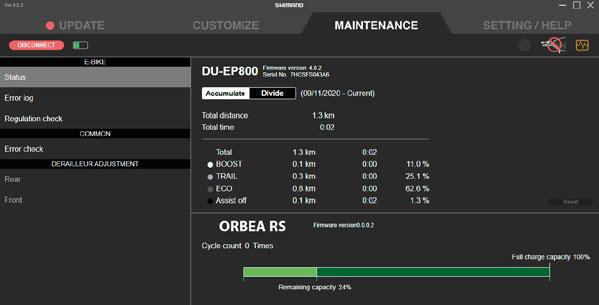
und schließe ein EW-SD300 Kabel beliebiger Länge vom Display zum Verbindungsadapter EW-JC304 an. Schließe
Schließe ein weiteres EW-SD300 Kabel beliebiger Länge an einem freien Anschluss des Verbindungsadapters anses Kabel in den EW-SD50 Kabelstandard zu überführen.bindungsadapters EW-JC304 mit dem Interface SM-PCE02 verwendet werden.
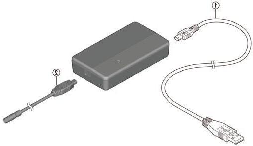
ORBEA RS AKKU IN ETUBE PROFESSIONAL
Wh ist über Etube Professional nicht möglich. Bei einer
nal, um auszuschließen, dass das Problem auf Shimano
Setze dich mit Shimano in Verbindung und lass dem Kun-mano dir mitteilt, dass das Problem mit dem integriertenfrage auf Kide an Orbea.
BLUE PAPER KEMEN 2022 114 | ORBEA ORBEA | 115
SC-EM800
Shimano SM-PCE02
EW-AD305
EW-SD300 EW-SD50
EW-JC304
SC-E5003
EW-AD305
EW-SD300
EW-SD300
TECHNISCHES HANDBUCH DE
EW-SD50 Shimano SM-PCE02
-
-
-
EW-SD50
MOTOR
SM-PCE02
EW-SD50 PCUSB-Kabel (Micro-USB)
20 GEPÄCKTRÄGER UND SCHUTZBLECHE
KEMEN ASPHALT
DATEN ZU GEPÄCKTRÄGER UND SCHUTZBLECHEN AM KEMEN ASPHALT
GEPÄCKTRÄGER
MATERIAL Aluminium
MAXIMALE BELASTUNG
KINDERSITZ MÖGLICH Nein
MONTAGE An Innengewinden der Ausfallenden und hinterem Schutzblech
MIK-KOMPATIBEL Nein
SEITLICHE ORTLIEB QL3.1
HALTERUNG Nein
Montage des hinteren Schutzblechs voraus.
träger darf nicht einfach nur an den Gewinden auf der Innenseite der Ausfallenden des Rahmens befestigt werden.
Das Kemen ist mit handelsüblichen Ge-
der Innenseite der Sitzstreben.
SCHUTZBLECHE
HERSTELLER Curana
MODELL
Apollo 65 mm
MATERIAL Aluminium
29 x 2,2"
MONTAGE VON GEPÄCKTRÄGER UND HINTE-
REM SCHUTZBLECH AM KEMEN ASPHALT Ersatzteile am Ende dieses Abschnitts.
MAXIMALE REIFENGRÖSSE
MONTAGE Siehe Abschnitt zur Montage
BLUE PAPER KEMEN 2022 116 | ORBEA ORBEA | 117 4 5 N.m 4 5 N.m 4 5 N.m 4 5 N.m 2 2 N.m M5 M5 M5 M4 TECHNISCHES HANDBUCH DE
-
MONTAGE DES VORDEREN SCHUTZBLECHS AM KEMEN ASPHALT
SETUPS MIT FOX 34 AWL FEDERGABEL
SETUPS MIT MARZOCCHI BOMBER Z2-E
Zur Befestigung des Schutzblechs an der steht oder du nicht weißt, wie man damit umgeht, solltest du die Montage von einemren lassen.
Ersatzteile am Ende dieses Abschnitts. Ersatzteile am Ende dieses Abschnitts.
BLUE PAPER KEMEN 2022 118 | ORBEA ORBEA | 119 TECHNISCHES HANDBUCH DE
3 3 N.m 3 3 N.m 3 3 N.m 3 3 N.m 3 3 N.m
KEMEN SUV
MIK & MIK HD
DATEN ZU GEPÄCKTRÄGER
UND SCHUTZBLECHEN AM KEMEN SUV
GEPÄCKTRÄGER
MATERIAL Aluminium
MAXIMALE BELASTUNG
KINDERSITZ MÖGLICHlich. Enthalten.
MONTAGE
Unten: Gewindeeinsätze auf der Innenseite der Ausfallenden Oben: hinteres Schutzblech.
MIK-KOMPATIBEL Ja. MIK HD (Heavy Duty). Siehe Abschnitt über MIK
SEITLICHE ORTLIEB QL3.1
HALTERUNG Ja. Siehe Abschnitt über Ortlieb QL3.1
Das Kemen ist mit handelsüblichen Ge-
der Innenseite der Sitzstreben.
SCHUTZBLECHE
HERSTELLER Curana
MODELL Apollo 70 mm
MATERIAL Aluminium
MAXIMALE REIFENGRÖSSE 29 x 2,35"
MONTAGE Siehe Abschnitt zur Montage
von Zubehör und Kindersitzen.
den.
Alle wichtigen Informationen über die Systeme MIK und MIK PLATTE (AM ZUBEHÖR BEFESTIGT)
MIK Website: Info zu MIK & MIK HD:
MIK-2022_catalogue_version8.pdf
MIK HD PLATTE (HEAVY DUTY) (AM ZUBEHÖR BEFESTIGT)
BLUE PAPER KEMEN 2022 120 | ORBEA ORBEA | 121 C TECHNISCHES HANDBUCH DE
-
-
-
ORTLIEB QL 3.1
hör mit QL3.1-Aufhängung befestigt werden.
MONTAGE VON GEPÄCKTRÄGER UND
HINTEREM SCHUTZBLECH AM KEMEN SUV
Ersatzteile am Ende dieses Abschnitts.
HERKÖMMLICHE SEITENTASCHEN
ORTLIEB QL3.1 SEITENTASCHEN
BLUE PAPER KEMEN 2022 122 | ORBEA ORBEA | 123 4 5 N.m 4 5 N.m 4 5 N.m 2 1.5 N.m 5 5 N.m 4 5 N.m 4 5 N.m 5 4 N.m see hole distance M5 M5 M5 TECHNISCHES HANDBUCH DE
-
BOHRUNG ZUR BEFESTIGUNG DES SCHUTZBLECHS AN DER SITZSTREBENBRÜCKE. ABSTAND
MONTAGE DES VORDEREN SCHUTZBLECHS AM KEMEN SUV
SETUPS MIT FOX 34 AWL
für die Schraube, mit der das Schutzblech an der Sitzan unterschiedlichen Stellen.
Wenn du das Hinterrad-Schutzblech für das Kemen mit einem 4 mm-Bohrer an der richtigen Stelle geam Rahmen montieren. Sieh dir die Tabelle in der folgenden Abbildung an und miss den Abstand zur Bohrungsmitte vom vorderen Ende des Schutzblechs aus.
Bohre das Loch genau mittig zur Schutzblechbreite.
Ersatzteile am Ende dieses Abschnitts.
Zur Befestigung des Schutzblechs an der steht oder du nicht weißt, wie man damit umgeht, solltest du die Montage von einemren lassen.
BLUE PAPER KEMEN 2022 124 | ORBEA ORBEA | 125 TECHNISCHES HANDBUCH DE
VORNE Lochabstand (D) HINTEN 4 mm Kemen SUV Größe S > D = 295 mm Kemen SUV Größe M > D = 320 mm Kemen SUV Größe L > D = 344 mm
3 3 N.m 3 3 N.m 2 1.5 N.m 2 1.5 N.m 3 3 N.m
KOMPONENTEN UND ERSATZTEILE
SETUPS MIT MARZOCCHI BOMBER Z2-E
Ersatzteile am Ende dieses Abschnitts.
GEPÄCKTRÄGER. ASPHALT & SUV
38GEPÄCKTRÄGERKEMENASPHALT
ARTNº:XB31BESTANDTEILEANZAHLWICHTIGEINFORMATIONEN
1
39GEPÄCKTRÄGERKEMENSUV
2 2 2 2
· Schutzblechmontage vorausgesetzt.
· Kemen Asphalt Modelle.
ARTNº:XB41BESTANDTEILEANZAHLWICHTIGEINFORMATIONEN 1
· Montage am hierfür vorgesehenen Sitzstre-
· Die Länge der an den Sitzstreben montierten Befestigungsstreben variiert je nach Rahmen-
Schraube M6 x 15 ISO7380 Streben2
SCHUTZBLECHE KEMEN ASPHALT
40HINTERRAD-SCHUTZBLECHKEMENASPHALT(KOMPLETT)
ARTNº:XB32BESTANDTEILEANZAHLWICHTIGEINFORMATIONEN Hinterrad-Schutzblech Curana Apollo. Aluminium. Schwarz. 65 mm1
Schutzblech-Spoiler. Kunststoff. Apollo 65 mm1
Streben. Apollo 65/340 mm. Schwarz1
Befestigung Strebe-Rahmen2
Schraube M5 x 25 ISO7380 Sitzrohr1
Unterlegscheibe M5 DIN125 Sitzrohr1
Spacer 15 mm Sitzrohr1
· Montage nur mit Kemen Asphalt enthalten.
BLUE PAPER KEMEN 2022 126 | ORBEA ORBEA | 127 3 3 N.m 3 3 N.m 2 1.5 N.m TECHNISCHES HANDBUCH DE
1 1 2 2 2 2
1 1
2 2 2
2
1
SCHUTZBLECHE KEMEN ASPHALT
41KLEINTEIL-KITHINTERRAD.SCHUTZBLECHKEMENASPHALT
ARTNº:XB33BESTANDTEILEANZAHLWICHTIGEINFORMATIONEN
Schutzblech-Spoiler. Kunststoff. Apollo 65 mm1
Streben. Apollo 65/340 mm. Schwarz1
Befestigung Strebe-Rahmen2
Schraube M5 x 25 ISO7380 Sitzrohr1
Unterlegscheibe M5 DIN125 Sitzrohr1
Spacer 15 mm Sitzrohr1
42SITZSTREBENBRÜCKESCHUTZBLECH.65-mm-ADAPTERFÜRKEMENASPHALT
ARTNº:XB23BESTANDTEILEANZAHLWICHTIGEINFORMATIONEN
Asphalt
Schraube M4 x 12 DIN7991 Sitzstreben2
44VORDERRAD-SCHUTZBLECH.KEMENASPHALT.MARZOCCHIBOMBERZ2-E.KOMPLETT
ARTNº:XB35BESTANDTEILEANZAHLWICHTIGEINFORMATIONEN
Vorderrad-Schutzblech Curana Apollo. Aluminium. Schwarz. 65 mm1
Kantenschutz Apollo 65 mm1
Schutzblech-Spoiler Kunststoff Apollo 65 mm1
· Setups mit Marzocchi Bomber Z2-E.
Strebe Apollo 65/245 mm. Schwarz1
Befestigung Strebe-Gabel2
Schelle Gabeltauchrohre D402
Schraube M5 x 20 ISO7380 Tauchrohrschellen2
Mutter M5 DIN985 Tauchrohrschellen2
45KLEINTEIL-KITVORDERRAD.SCHUTZBLECH.KEMENASPHALT.FOX-MARZOCCHI
ARTNº:XB36BESTANDTEILEANZAHLWICHTIGEINFORMATIONEN
Kantenschutz Apollo 65 mm1
Schutzblech-Spoiler Kunststoff Apollo 65 mm1
1 1 1 1
Strebe Apollo 65/245 mm. Schwarz1
Befestigung Strebe-Gabel2
Schraube M5 x 16 DIN7380 Streben2
43VORDERRAD-SCHUTZBLECH.KEMENASPHALTFOXAWL.KOMPLETT
ARTNº:XB34BESTANDTEILEANZAHLWICHTIGEINFORMATIONEN
Vorderrad-Schutzblech Curana Apollo. Aluminium. Schwarz. 65 mm1
Kantenschutz Apollo 65 mm1
Schutzblech-Spoiler. Kunststoff Apollo 65 mm1
· Setups mit Fox AWL
· Die bei Marzocchi Setups vorgesehene obere Befestigung wird bei Fox AWL Setups nicht verwendet. enthalten.
· Marzocchi Tauchrohrschellen nicht enthalten.
· Streben-Tauchrohr-Platten für Fox AWL nicht enthalten.
Strebe Apollo 65/245 mm. Schwarz1
Befestigung Strebe-Gabel2
Platte zur Strebenbefestigung an Fox AWL2
Schraube M5 x 10 ISO7380 Gabeltauchrohre2
Schraube M5 x 16 DIN7380 Streben2
Mutter M5 DIN985 Streben2
· Zur Befestigung des Schutzblechs an der werden.
Mutter M5 DIN985 Streben2
46STREBEN-TAUCHROHR-PLATTENFOXAWL.KITASPHALT-SUV
ARTNº:XB38BESTANDTEILEANZAHLWICHTIGEINFORMATIONEN Platte zur Strebenbefestigung an Fox AWL2
Schraube M5 x 10 ISO7380 Gabeltauchrohre2
Schraube M5 x 16 DIN7380 Streben2
Mutter M5 DIN985 Streben2
47SCHELLENSATZFÜRTAUCHROHRE.MARZOCCHIBOMBERZ2-E.ASPHALT-SUV
· Geeignet für mit Fox AWL Gabeln ausgestattete Asphalt- und SUV-Modelle des Kemen.
ARTNº:XB39BESTANDTEILEANZAHLWICHTIGEINFORMATIONEN Schelle Gabeltauchrohre D402
Schraube M5 x 20 ISO7380 Tauchrohrschellen2
Mutter M5 DIN985 Tauchrohrschellen2
· Geeignet für mit Marzocchi Bomber Z2-E Gabeln ausgestattete Asphalt- und SUVModelle des Kemen.
BLUE PAPER KEMEN 2022 128 | ORBEA ORBEA | 129 TECHNISCHES HANDBUCH DE
2 2 2 2
1
1 1 1 2
1 1 1 1
1
SCHUTZBLECHE KEMEN ASPHALT
48SCHUTZBLECHBEFESTIGUNGANGABELBRÜCKE.MARZOCCHIBOMBERZ2-E.KEMENASPHALT-SUV
ARTNº:XB37BESTANDTEILEANZAHLWICHTIGEINFORMATIONEN
51SITZSTREBENBRÜCKEGEPÄCKTRÄGER.KEMENSUV
ARTNº:XB44BESTANDTEILEANZAHLWICHTIGEINFORMATIONEN 1
Schraube M4 x 16 ISO7380 Kettenstreben2
· Die unteren Spacer werden bei den SUV-Modellen des Kemen nicht verwendet.
SCHUTZBLECHE KEMEN SUV
49HINTERRAD-SCHUTZBLECHKEMENSUV(KOMPLETT)
ARTNº:XB42BESTANDTEILEANZAHLWICHTIGEINFORMATIONEN
Hinterrad-Schutzblech Curana Apollo. Aluminium. Schwarz. 70 mm1
Schutzblech-Spoiler. Kunststoff. Apollo 10 mm1
Schraube M3 x 6 ISO7380 Spoiler2
· Vor der Montage muss ein Loch für die werden. Informationen zur Lochposition sind im Abschnitt zur Montage enthalten.
Unterlegscheibe M4 DIN125 Kettenstreben2
52VORDERRAD-SCHUTZBLECH.KEMENSUV.FOXAWL.KOMPLETT
ARTNº:XB45BESTANDTEILEANZAHLWICHTIGEINFORMATIONEN Vorderrad-Schutzblech Curana Apollo. Aluminium. Schwarz. 70 mm1
Kantenschutz Apollo 70 mm1
Schraube M3 x 6 ISO7380 Kantenschutz1
Spoiler Orbea 70 mm1
Schraube M3 x 6 ISO7380 Spoiler2
· Setups mit Fox AWL Gabeln.
· Zur Befestigung des Schutzblechs an der werden.
Schraube M5 x 15 ISO7380 Sitzrohr1
Unterlegscheibe M5 DIN125 Sitzrohr1
Spacer 4,5 mm Sitzrohr1
50KLEINTEIL-KITHINTERRAD.SCHUTZBLECHKEMENSUV
ARTNº:XB43BESTANDTEILEANZAHLWICHTIGEINFORMATIONEN
Schutzblech-Spoiler. Kunststoff. Apollo 10 mm1
Schraube M3 x 6 ISO7380 Spoiler2
Schraube M5 x 15 ISO7380 Sitzrohr1
Unterlegscheibe M5 DIN125 Sitzrohr1
Spacer 4,5 mm Sitzrohr1
Strebe Apollo 70/350 mm. Schwarz1
Befestigung Strebe-Gabel2
Platte zur Strebenbefestigung an Fox AWL2
Schraube M5 x 10 ISO7380 Gabeltauchrohre2
Schraube M5 x 16 DIN7380 Streben2
Mutter M5 DIN985 Streben2
53VORDERRAD-SCHUTZBLECH.KEMENSUV.MARZOCCHIBOMBERZ2-E.KOMPLETT
ARTNº:XB46BESTANDTEILEANZAHLWICHTIGEINFORMATIONEN
Vorderrad-Schutzblech Curana Apollo. Aluminium. Schwarz. 70 mm1
Kantenschutz Apollo 70 mm1
Schraube M3 x 6 ISO7380 Kantenschutz1
Spoiler Orbea 70 mm1
Schraube M3 x 6 ISO7380 Spoiler2
Strebe Apollo 70/350 mm. Schwarz1
Befestigung Strebe-Gabel2
· Setups mit Marzocchi Bomber Z2-e.
Schelle Gabeltauchrohre D402
Schraube M5 x 20 ISO7380 Tauchrohrschellen2
Mutter M5 DIN985 Tauchrohrschellen2
BLUE PAPER KEMEN 2022 130 | ORBEA ORBEA | 131 TECHNISCHES HANDBUCH DE
1
1 1 2
1 1 1
1
1 1 1
1 1 1 1 1
1
1 1 1 1 1
1
SCHUTZBLECHE KEMEN SUV
54KLEINTEIL-KITSCHUTZBLECHE.VORDERRADKEMENSUV.FOX-MARZOCCHI
ARTNº:XB47BESTANDTEILEANZAHLWICHTIGEINFORMATIONEN
Kantenschutz Apollo 70 mm1
Schraube M3 x 6 ISO7380 Kantenschutz1
Spoiler Orbea 70 mm1
Schraube M3 x 6 ISO7380 Spoiler2 1 1 1 1
Strebe Apollo 70/350 mm. Schwarz1
Befestigung Strebe-Gabel2
46STREBEN-TAUCHROHR-PLATTENFOXAWL.KITASPHALT-SUV
Die bei Marzocchi Setups vorgesehene obere Befestigung wird bei Fox AWL Setups nicht verwendet.
enthalten.
Marzocchi Tauchrohrschellen nicht enthalten. Streben-Tauchrohr-Platten für Fox AWL nicht enthalten.
EINSTELLUNG DER FOX UND MARZOCCHI GABELN
HERSTELLERHANDBÜCHER
BENUTZERHANDBUCH ZU MARZOCCHI GABELN:
ARTNº:XB38BESTANDTEILEANZAHLWICHTIGEINFORMATIONEN
Platte zur Strebenbefestigung an Fox AWL2
Schraube M5 x 10 ISO7380 Gabeltauchrohre2
Schraube M5 x 16 DIN7380 Streben2
Mutter M5 DIN985 Streben2
47SCHELLENSATZFÜRTAUCHROHRE.MARZOCCHIBOMBERZ2-E.ASPHALT-SUV
EINSTELLHILFE ZU FOX UND MARZOCCHI RAIL KARTUSCHEN-GABELN:
· FOX 34 FLOAT AWL RAIL, 29", 100 mm QR15 X 110
· MARZOCCHI BOMBER Z2 29", 100 mm, E-BIKE+, RAIL, QR15 X 110
Geeignet für mit Fox AWL Gabeln ausgestattete Asphalt- und SUV-Modelle des Kemen.
RICHTWERTE ZUM EMPFOHLENEN SAG UND
LUFTDRUCK VON FOX UND MARZOCCHI GABELN:
Die folgenden Tabellen enthalten ungefähre Einstellungswerte, die abhängig vom Fahrstil und Untergrund des Ge-
ARTNº:XB39BESTANDTEILEANZAHLWICHTIGEINFORMATIONEN
Schelle Gabeltauchrohre D402
Schraube M5 x 20 ISO7380 Tauchrohrschellen2
Mutter M5 DIN985 Tauchrohrschellen2
Geeignet für mit Marzocchi Bomber Z2-E Gabeln ausgestattete Asphalt- und SUV-Modelle des Kemen.
48SCHUTZBLECHBEFESTIGUNGANGABELBRÜCKE.MARZOCCHIBOMBERZ2-E.KEMENASPHALT-SUV
ARTNº:XB37BESTANDTEILEANZAHLWICHTIGEINFORMATIONEN
Die unteren Spacer werden bei den SUV-Modellen des Kemen nicht verwendet.
EMPFOHLENER SAG Gesamtfederweg der Gabel 15 % SAG (hart) 20 % SAG (sanft)
Marzocchi Bomber Z2 RAIL 100 mm 15 mm20 mm
Fox 34 Float AWL 100 mm 15 mm20 mm
BLUE PAPER KEMEN 2022 132 | ORBEA ORBEA | 133 TECHNISCHES HANDBUCH DE
DÄMPFER
21
1
1 2
1
EMPFEHLUNG FÜR DIE ZUGSTUFENEINSTELLUNG
VON FOX UND MARZOCCHI GABELN
EMPFOHLENER LUFTDRUCK ZUR SAG-EINSTELLUNG
MARZOCCHI BOMBER Z2 RAIL & FOX 34 FLOAT AWL RAIL
Gewicht Fahrer:in+Ausrüstung (kg)Gewicht Fahrer:in+Ausrüstung (lb)Druck (psi)
54 - 59120 - 13065
59 - 64130 - 14070
64 - 68140 - 15074
68 - 73150 - 16080
73 - 77160 - 17085
77 - 82170 - 18090
82 - 86180 - 19096
86 - 91190 - 200101
91 - 95200 - 210106
95 - 100210 - 220111
100 - 104220 - 230116
104 - 109230 - 240121
109 - 113240 - 250126
LUFTVOLUMEN-SPACER BEI MARZOCCHI UND FOX GABELN
von Luftvolumen-Spacern einstellen, die bei einem autorisierten Fox Händler erhältlich sind.
Marzocchi
FederwegWerkseitig verbaut
Die folgenden Tabellen enthalten ungefähre Einstellungswerte, die abhängig vom Fahrstil und Untergrund des Ge-sinn wie in der Tabelle angegeben.
EMPFOHLENE ZUGLUFTEINSTELLUNGEN MARZOCCHI BOMBER Z2 RAIL & FOX 34 FLOAT AWL RAIL
Gewicht Fahrer:in+Ausrüstung (kg)Gewicht Fahrer:in+Ausrüstung (lb)Klicks
54 - 59120 - 13010
59 - 64130 - 1409
64 - 68140 - 1509
68 - 73150 - 1608
73 - 77160 - 1708
77 - 82170 - 1807
82 - 86180 - 1907
86 - 91190 - 2006
91 - 95200 - 2105
95 - 100210 - 2203
100 - 104220 - 2302
104 - 109230 - 2401
109 - 113240 - 2501
EMPFOHLENE DRUCKSTUFENEINSTELLUNGEN
FÜR MARZOCCHI UND FOX RAIL GABELN -
Die Hebelpositionen zwischen dem OFFENEN und HAR-stufendämpfung.
die restlichen Positionen je nach Gelände und Bedingungen zu verwenden.
BLUE PAPER KEMEN 2022 134 | ORBEA ORBEA | 135 TECHNISCHES HANDBUCH DE
Maximale
Spaceranzahl
Bomber Z2
100 mm 66 Fox 34 Float AWL RAIL 100 mm 66
RAIL
KONFORMITÄTSERKLÄRUNG 23 ZUSÄTZLICHE INFORMATIONEN

ORBEA ist mit einer grandiosen, globalen Community von Suchst du neue Herausforderungen für dich und dein Fahrrad? Oder vielleicht ein tolles Ziel für den Fahrradurlaub? Hier hat bestimmt jemand einen spannenden Tipp
FACEBOOK TWITTER
www.twitter.com/Orbea/
YOUTUBEwww.youtube.com/user/OrbeaBicycles
INSTAGRAM
www.instagram.com/orbeabicycles
ORBEA CONTENT
content.orbea.com/us-en/
BLOG ORBEA
www.orbea.com/de-de/blog
ORBEA VERKAUFSSTELLEN
unterstützen. Die vollständige Übersicht unseres Händlerwww.orbea.com/de-de/dealers/?country=INT
KONTAKT
www.orbea.com/de-de/contacto
www.orbea.com/de-de/contact/
BLUE PAPER KEMEN 2022 136 | ORBEA ORBEA | 137 TECHNISCHES HANDBUCH DE 22
WWW.ORBEA.COM
