11 minute read
Optimum fl ow technology
OPTIMUM FLOW

TECHNOLOGY

Tom Ventham, Unicat B.V. & G. W. Aru, LLC, looks at how to unlock SMR catalyst reformer profitability, with uniform tube packing and improved flow patterns.

In almost every industrial application, advances fi rst focus on areas of catalytic improvement. Steam methane reforming is no different, but nickel catalysis improvement has plateaued. This leaves operators in a quandary. Changes in market demands and product specifi cations, as well as advances in adjacent catalyst technologies – from hydrocracking1 to ammonia synthesis2,3 – necessitate greater hydrogen output. However, in most cases hydrogen remains unscalable from existing equipment without expensive retrofi t. Moreover, as a highly energy intensive process, and thus a major CO2 emitter, steam methane reformer (SMR) operators are mandated to attain new levels of effi ciency for sustainability reasons.
Aware that many in the industry were nervous about this seemingly unassailable issue, Magma Catalysts & Ceramics (now part of Unicat Catalyst Technologies LLC) has developed an alternative way to produce catalyst for reformers. Importantly, MagCat catalytic behaviour is nearly identical to existing SMR catalysts, as it similarly uses nickel as the active ingredient. However, its shape, size, and physical properties change how fl uid fl ow passing through reformer tubes interacts with solid catalyst. Consequences of these fl ow changes impact energy

transfer; a critical limiting factor in highly endothermic reaction systems. Furthermore, improvements inherent in the design of the catalyst technology mean that benefi ts can last longer into the cycle, unlocking value potential. This article offers readers a visualisation of an alternative approach to packed-tube SMR loadings.
Shape and size
Previously published articles have discussed in detail how differences in MagCat production give new possibilities in terms of optimised size, minimal drag, spherical shape, and ability to add surface texturing and sub-surface porosity.4 This article takes a macro view to show how the catalyst technology responds dynamically in hot reformer tubes and how this becomes the true realisation of benefi ts that can be valorised by operators.
Improved loading technique
To begin this thought experiment, let us consider loading MagCat to the reformer. Several years ago, smart operators identifi ed dense loading of reformers using springs suspended on wires to slow catalyst pellet average drop velocity and give benefi ts over traditional sock fi lling techniques. Dense loading can improve cold-tube pressure drop profi les by reducing pellet breakage when dropping from height. The number of rejected tubes outside dP tolerance reduces, and sometimes a lower overall loading time is experienced. In addition, dense loading can allow 3 – 7% more traditional-shaped cylindrical catalyst pellets to be loaded in a given tube.5 This directly translated to surface area increase which was commonly becoming a limiting factor for many reformers pushed to produce more hydrogen at higher outlet temperatures.
Although dense loading MagCat remains feasible and can be preserved as a predilection of decision makers, rigorous testing and evaluation has proven that if the catalyst technology is dropped directly into reformer tubes it will not result in excessive breakages or loading profi le inconsistencies. Very high strength properties and spherical shape mean that the catalyst technology automatically arranges into uniform packing patterns in every tube loaded, thus achieving maximum catalyst quantity in each tube. This criticality to load as many pellets as possible, to avoid activity or cycle length limitations, is less signifi cant for MagCat fi lled reformers due to increased particle surface area. To achieve certainty of good reformer operation, it is important to examine responses of catalyst types in heated tubes and over a cycle comprising several shutdowns.


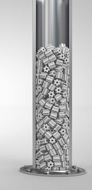
Figure 1. Example of Magma/Unicat test rig filled with wagon wheel cylindrical catalyst.
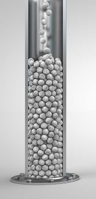
Figure 2. Computer simulation of Magcat packing in cold or hot operations.
Catalyst dynamics in a thermally cycled reformer tube
Step one: loading
Assume two scenarios. One is a steam reformer, well-loaded with traditional cylindrical SMR catalyst using dense loading methods and attaining dP tolerances of 3% or less. Although such loadings can be defi ned as acceptable under cold conditions, shape characteristics of cylindrical catalysts mean loading patterns (when viewed cross-sectionally at points along the tube) are chaotic, random, and non-repeating through the length. The second situation is an identical reformer with MagCat, fi lled using sock loading or dense loading technique if preferred by the user (differences are not expected using either technique). Spherical shapes have complete rotational and refl ection symmetry and dynamic properties to roll and pivot into openings, due to a naturally low moment of inertia which results in optimised packing. Cold pressure drop measurement across these two catalyst loadings (assuming similar particle diameter) will show lower deltas for MagCat. Symmetrical, spherical shapes impart less drag than bluff cylinders orientated in all


possible axes. Additionally, bed voidage with MagCat is higher due to regular and uniform spaces between adjacent spheres, controlled by assigning appropriate sphere size for each reformer. Randomly packed cylinders have voidage defi ned by holes through the piece as well as irregular gaps (or no gaps) between adjacent particles. Selecting smaller MagCat sizes achieves constant pressure drop with improved radial heat transfer and activity. For example, a constant catalyst size is maintained for both MagCat and traditional cylindrical catalyst loadings.
Step two: heating
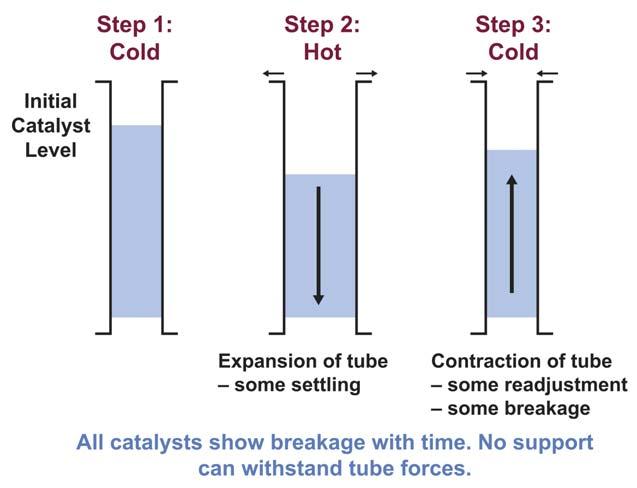
As reformers heat at start-up, metal tubes expand. Although solid pellets also experience increasing volume, this is slight as there is lower coeffi cient of thermal expansion (CTE) for ceramic materials than metal alloy reformer tubes. In systems dense loaded with cylindrical type catalyst, increased available bed diameter results in catalyst dropping down tubes as pellets, reordering themselves to fi ll gaps. Rearrangement of catalyst happens in an uncontrolled way that cannot be checked, verifi ed, or repeated. Randomly packed systems become more chaotic as bridges form, as well as areas of tightly packed catalyst with little room for uniform gas fl ow.
Bed void space, or bulk voidage, is another way to examine this effect. This mathematical measurement compares available reactor volume, in this case thermally expanded cross-sectional area multiplied by original catalyst fi ll height, over volume of solid material in the bed, i.e. catalyst pellets. Bulk voidage is a powerful comparison for measuring changes in dynamic systems as some parameters remain consistent; expanded tube volume is considered constant over comparison cases, and particle internal voidage is also assumed initially fi xed (i.e. assumes no breakage). Moreover, calculation of bulk voidage can be directly translated to bed pressure drop via Ergun’s equation.6 As void fraction increases, pressure drop reduces:
Pressure drop = A/V (1- ε)/ε3
Where ε = the void fraction (porosity) of the bed, A = area, and V = volume.
Bulk voidage of freshly packed, cold tubes is a function of particle internal void fraction and interstitial void space between adjacent particles. When tubes expand internal void, fraction remains fi xed, but interstitial voidage varies as particles move and reorder. In traditional cylindrical catalyst fi lls, when hot tubes expand and cylinders reorder, catalyst level drops. Mathematical simulation work of this scenario shows overall bed voidage reducing, as catalyst rearranges and squeezes out interstitial voidage. This means pressure drop increases in traditionally fi lled, cylindrically-shaped catalyst as tubes heat and voidage reduces.
MagCat spheres respond differently in heated tubes. Uniform packed beds, when sock loaded or dense loaded, respond predictably and repeatably as tube diameter increases. Investigations show that outer-ring spheres move to stay in contact with the wall, conducive to good transfer of heat into the bed. Spheres adjacent to this outer-ring move less in comparison. This follows through to spheres in a central core that barely move from original positions. Properties of spheres, particularly when textured to add frictional roughness, allow both fl uent movement of outer spheres that fan-out to maintain essential wall contact, as well as a centre benefi ting from adherent characteristics of regular, uniform packing to hold and maintain frameworks based on fundamental principles of structural shape arrangements.
As opposed to beds using traditional cylindrical catalyst, catalyst fi ll heights in tubes loaded with MagCat do not drop signifi cantly in a hot system. This results in increased bulk voidage in expanded tube volumes. A stable catalyst core and uniform packing with spheres means large


Figure 3. Uniform packed reformer tubes vs random packing.
Figure 4. Sequence of thermal cycling in reformer tubes.

Figure 5. Impact on flow from catalyst type.
voids will not be present to cause cascades of pellets down the bed or signifi cant rearrangements from initial loading. By preserving bed height and thus increasing voidage, Ergun’s equation shows pressure drop with MagCat reduces at start-up rather than increasing, as experienced with traditional reformer catalysts.
A further benefi t of operating with this type of spherical catalyst loading is fl ow patterns. As reactant gases pass vertically through the bed, and energy in the form of heat moves laterally from heated walls, the catalyst position remains uniform throughout the tube. This is highly conducive to even reaction rates; maximising conversion and minimising temperature hot spots. Flow uniformity and elimination of dead spots, back-eddies, and no-fl ow regions minimises methane slip values and extends cycle lengths by accessing available catalytic activity and advancing tube lifetimes.

Conclusion
Step three: cooling
For any typical hydrogen plant cycle, numerous shutdowns will be experienced. Some shutdowns are determined by scheduled or unscheduled events affecting downstream units, whereas others will be directly related to issues or occurrences in the hydrogen plant. Different units experience different regularities of shutdown, but all reformer units expect to shutdown several times during a typical cycle. Furthermore, frequent variations in hydrogen production requirements, other operational deviations, and furnace changes (e.g. fl uctuating fuel calorifi c values if using PSA purge gas) create both minor and more major temperature variations throughout the catalyst cycle.
During cool down, reformer tubes contract in the direction of original internal diameter. In traditional cylindrical catalyst loadings, this process is associated with impending catalyst breakage as tightly packed pellets. Having rearranged to wider diameter tubes, it is not possible to reorientate back to the original positions of the cold tube. Shape and randomness of packing result in pieces locking together rather than shifting position in response to kinetic contracting forces. This results in breakage. Consequences of thermal cycling include pressure drop increases over the run as well as activity reductions. Voidage reduces further upon each shutdown and catalyst fi ll level falls as crushed catalyst loses structure and establishes narrower vapour pathways through the bed. MagCat spheres respond differently in cooling tubes. During heat up and operation, the outermost spheres stretch out, staying in contact with the tube wall. When cooling, spheres that have incrementally moved now relax; reorientating to original positions through a series of successively smaller shifts approaching the centre. Symmetry and ball-like shape allow the catalyst technology to move and roll without interlocking. Contraction forces are distributed evenly around the tube circumference and into the centre. This avoids weak-points of focusing unbalanced stresses on sacrifi cial pellets crushed to absorb forces acting on the bed.
Catalyst fi ll level, which minimally reduced during warming or operation with MagCat, is maintained at or close to original level and the natural uniformity of spherical packing is retained. Higher crush strength of the catalyst technology resists breakage during operational temperature fl uctuations that produce minor changes in tube diameter, by encouraging reorientation of particles rather than breaking. No catalyst crush strength is high enough to impose excessive stress on tubes.
Long-term observation with MagCat will be reduced gradient of pressure drop increase over time and retention of activity, as witnessed by maintenance of low methane slip through the cycle. This is additional to lower initial pressure drop due to a naturally optimised shape for minimal drag, consistent and uniform packing profi le, and higher (instead of lower) bulk voidage during warm up.
This article has detailed a fundamental shift in how to deploy heterogeneous catalyst in tubular reformers, such as those used to generate hydrogen at refi nery sites or other syngas producers. Attention previously given to optimisation of catalytic chemistry is yielding ever diminishing returns. Focus must now switch to the support ensuring fl uid dynamic, mechanical, and heat transfer properties maximise economic and operational returns from existing equipment.
References
1. MALDONADO X. E. R., PRIETO, C. M., UTRERA, J. C. E., and
RODRIGUEZ, J. P., ‘Boosting mild hydrocracking performance’, (August 2020), https://www.digitalrefining.com/article/1002457/ boosting-mild-hydrocracking-performance 2. FULLER, J., FORTUNELLI, A., GODDARD III, W. A., and AN, Q.,
‘Discovery of Dramatically Improved Ammonia Synthesis Catalysts through Hierarchical High-Throughput Catalyst Screening of the Fe(211) Surface’, Chem. Mater, 2020, 32, 23, 9914 – 9924 (17 November 2020), https://pubs.acs.org/doi/10.1021/acs. chemmater.0c02701 3. HUMPHREYS, J., LAN, R., and TAO, S. ‘Development and Recent
Progress on Ammonia Synthesis Catalysts for Haber–Bosch
Process’, (10 December 2020), https://onlinelibrary.wiley.com/doi/ full/10.1002/aesr.202000043 4. BENNINGTON, G. and VENTHAM, T., ‘21st Century Hydrogen’,
Hydrocarbon Engineering, (March 2021), pp. 32 - 36. 5. https://www.unidense.com/technology 6. MACDONALD, I. F., EL-SAYED, M. S., MOW, K. and DULLIEN, F. A. L.,
‘Flow through Porous Media-the Ergun Equation Revisited’,
Ind. Eng. Chem. Fundamen, 1979, 18, 3, 199 – 208, (1 August 1979), https://pubs.acs.org/doi/abs/10.1021/i160071a001


