
13 minute read
More Pressure, Less Problems: Part One


In the first part of a two-part article, Steve Meiring, PasteTech Pty Ltd, Australia, provides a comprehensive comparison of the pressures of various dewatering technologies for fine coal tailings.

The Australian coal industry has, for many years, utilised belt press filters to dewater fine thickened tailings. Recently, solidbowl centrifuges have been introduced as an alternate technology to dewater tailings.
Both dewatering technologies have been in the industry for over 60 years and are well-accepted dewatering methods. However, tailings technologies have recently become more demanding. Globally, other coal tailings plants are successfully utilising plate and frame pressure filters. This article will look at these three technologies and how they are used to meet tailings requirements.
While each application is uniquely diff erent, a common criterion applies, namely to dewater fine solids to meet an acceptable transport


and deposition criterion. While numerous dewatering bench scale and pilot plant tests are utilised to determine the extent of the dewatering, a number of fundamental diff erences in the technologies can be found.
The factors influencing the sizing of centrifuges, belt press filters and plate and frame pressure filters are provided, together with a look at the diff erent process variables that have an impact on each application.
Filtration is a process where slurry is forced through a media with the solids retained on the media/solids and the liquid passing through. In coal tailings, the fine solids tonnage is generally the smaller of the two reject streams exiting the plant, but it has a greater volume of water. Water removal must therefore be targeted to transportable limits and within transportable costs. The transportable limit is a design criterion for the dewatering technology, hence equipment should be selected based upon its ability to reliably achieve the required moisture, handling, and deposition characterisation. An amount of water will always remain in the dewatered cake, which should be managed and have no detriment eff ect on technologies following the technology.
The technical analysis and comparison of the technologies in delivering a handleable material has at times fallen short of an acceptable standard. As such, each application requires an extensive process review. This article addresses the more important process diff erences between the technologies and provides the advantages and disadvantages for each.
Australian background Comparison of technologies
While there are numerous factors that contribute to the performance of dewatering technologies, this comparison considered a typical tailings thickener underflow at 35% w/w solids, dewatering flotation tails. For the comparison, a particle size with 67% passing 53 micron was utilised.
Industry dewatering technologies and typical results
Over the last 10 years, dewatering equipment has grown larger, with more eff icient designs. In order to complete a representative comparison of equipment, the largest successful operating installation was considered. This included: 3 m wide belt press filter. 1000 mm dia. solidbowl centrifuge. 2 m wide x 2 m high x 200 plate, plate and frame pressure filter (air blow optional).
Data from vendors and published results have been compared.
In Australia, numerous plants utilise 3 m wide belt press filters for tailings dewatering. This technology is considered acceptable in the industry; however, with higher tonnages and greater demand to move to dry disposal, other technologies are being considered. There are three plants utilising solidbowl centrifuges. Historically, batch type plate and frame filters have not functioned well in Australia on coal tailings, but numerous other countries have found favourable advantages with high-pressure filters. Over the past 10 years, a number of plants worldwide have installed plate and frame pressure filters.
Table 1. Typical tailing dewatering results
Application Recovery (%) Moisture (%) Plate and frame filter + 98 26 – 30
Belt press filter 90 – 97* 34 – 38* Solidbowl centrifuge 92 – 99* 30 – 36*
* Dependent on polymer addition and particle size distribution. Recovery and moisture
Table 2. Typical solids and volumetric throughput
Application Approximate area (m2) Typical dry (tph) Typical m3/h at 35% w/w U/F
2 m x 2 m plate and frame filter (200) 3 m wide belt press filter
1000 mm dia. solidbowl centrifuge The plate and frame pressure filter provides the highest recovery, followed by the solidbowl and the belt press filter. The plate and frame pressure filter provides the lowest moisture, followed by the solidbowl and the belt press filter (Table 1). The removal of water in a belt press filter is derived via compression through mechanical pressure and shear. The product moisture of the plate and frame filter, while lower than the belt press filter and centrifuge, is achieved through the higher pressure applied and the air blow. An added advantage of the pressure filter is that simply adjusting air-blowing time can control cake moisture. Most of the belt press filter losses do 1433 75 183.4 not occur through the sides or mesh of the belt, as may be expected, but rather 27 19 46.5 due to residual cake sticking to the belt and being lost in the high-pressure wash water. This is a characteristic of the tailings 4.65 50 122.3 as well as a function of the selected belt composition.
In centrifugation, both the G-force (G) (related to diameter and speed) and retention t ime (T) and in some instances diff erential speed must be considered. It is for this reason a GT curve is produced. The G and T are multiplied together to provide G seconds and a series of either moistures or recoveries are depicted for the diff erent G-second scenarios together with particle size distributions and reagent additions.
Solids and volumetric throughput
Table 2 shows typical values of solids throughput and is dependent on numerous factors.
For each of the three technologies, residence and or filtration time plays a major role in its sizing.
Sizing of a belt press filter is based on the filtration characteristics and the time required to meet a desired cake moisture.
Tailings thickener underflow solids move up and down the ‘density curve’ based on the characterisation of the material, water, and how the operators run the thickener. It is therefore of more benefit to scale up or size a centrifuge on volume and retention time as opposed to solids tonnage rate. From a process standpoint, either the recovery or the cake solids set the limit on the volumetric throughput
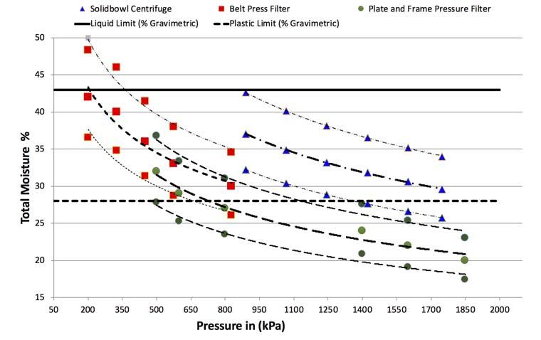
Figure 1. Total moisture range vs applied pressure. For each technology, the upper, average, and lower moistures are depicted. to the centrifuge. Subject to the mechanical constraints of the machine, a centrifuge operation is a trade off of both functions. Sizing of a plate and frame filter typically involves a solids rate per unit area within an acceptable batch cycle time. Pressure and plastic limits The applied pressure exerted on coal fine tailing particles has an aff ect on the total moisture. Figure 1 depicts the various application pressures vs the

OUR EXPERIENCE –YOUR ADVANTAGE
The perfect grabs with unbeatable reliability, leading in efficiency and quality, expedient and economical.
Rope-, Motor-, Hydraulic-Grabs
MRS GREIFER GmbH
Talweg 15-17 • 74921 Helmstadt • Germany Tel: +49 7263 912 90 • Fax: +49 7263 912 912 export@mrs-greifer.de • www.mrs-greifer.de
total moisture. The belt press filter pressure exerted through the air driven bellows can range between 200 and 830 kPa. The pressure diff erential between the pool and the cake in a solidbowl centrifuge can be between 800 kPa and upward of 2000 kPa. The plate and frame pressure filter pressure based on the feed pump can reach pressures of over 2000 kPa.
It is interesting to note that the curve for all technologies follows a similar shaped pattern (Figure 1). The total moisture therefore should be selected based on the cake properties, in particular the cake’s Atterberg Limits.
The Atterberg Limits describe the plasticity of the dewatered material, an important criterion required for transportation and deposition in dumps. The liquid limit (LL) is the gravimetric moisture content at which the material starts to flow and the plastic limit (PL) is the gravimetric moisture content as the material starts to act as a solid. These must be determined for the diff erent dewatered cakes. The plasticity index (PI) is defined as the diff erence between the LL and the PL. Plasticity is defined as the degree of deformation the cake can withstand while maintaining its volume in reaction to a force. The higher the plasticity the higher the force for a change in structure.
Mineralogical composition, particle size, reagents, dewatering application, and operating modes influence the degrees of change. ACARP project C15061 showed that the plasticity had a direct impact on handling and the ‘deposited’ geotechnical properties. Results indicated that higher plasticity is associated with decreased permeability and shear strength, and increased compressibility and swell potential.
The Atterberg Limits require comparison against the cake moisture content. The results show the solids concentration and the associated characterisation of filter cake. An example includes: An easily handled friable cake: that is a solids concentration higher than the PL (for example >72% solids). An intermediate phased plastic material: that is a solids concentration between the PL and LL (between 56% and 72% solids). A very diff icult to handle flowable material: that is a solids concentration less than the LL (<56% solids).
Table 3. Typical reagent consumption Application Flocculant Coagulant (g/dry t) (g/dry t) Plate and frame filter 0 0
Belt press filter 50 – 300 50 – 300
Solidbowl centrifuge 200 – 600 100 – 300
Table 4. Centrifuge residence time at 25 and 35% solids Feeds % solids Volumetric flow (m3/h) Retention time (sec.) 35 123 38
25 179 26 Reagents
The addition of reagents is determined via testwork and the characterisation of the tailings (Table 3).
With the introduction of high-pressure filtration, the need for reagents is optional. Some plate and frame filters that are not utilising high pressure may require reagents.
The majority of all belt press filters require feed conditioning prior to the feed entering the filter. Both anionic and cationic reagents are required in some applications.
The solidbowl centrifuge will not recover ultra fines without the addition of reagents. The recovered ultra fines then add moisture to the final cake. It is therefore imperative to review the quantity of -20 micron material in the feed, cake, and centrate sample.
Major factors infl uencing dewatering
Feed percent solids
The feed percent solids content for a dewatering application has an eff ect on sizing and performance. Higher volumes of water need to be managed and, where possible, the removal of water (to acceptable levels) prior to the dewatering application is the preferred norm.
In many coal processing plants, thickeners are used for the initial dewatering of tailings. The underflow from the thickener serves as the feed to a more intense dewatering application. Increasing the underflow solids concentration can be an advantage or disadvantage to dewatering, depending on the selected application.
Plate and frame pressure fi lters
Higher feed solids to a plate and frame filter reduces the overall cycle time. Cake formation in the plate and frame filter is governed by Darcy’s Law. The basic formula for cake to establish on a filter cloth is:
dV/dt = 7.481*P/(µ*(aave W+R m) [1]
Where: V = the filtrate liquid volume per unit filtration area (m3/m2). t = cake formation time (min.). P = applied pressure across the cake or bed of solids (kg/m2). µ = viscosity of the liquid (kg-min./m2). aave = specific filtration resistance of the cake or bed of solid (m/kg).
W = mass of solids cake per unit filtration area (kg/m2). Rm = filter cloth resistance (1/m).
With a variable thickener underflow feed concentration, Darcy’s equation can be arranged in this manner:
dt/dV = µ*( aaveSV/A+Rm)/AP [2]
Where: S = solids concentration of the feed slurry (kg/m3).
By integrating and rearranging equation [2], it shows that the cake formation time (t) can be influenced by the feed percent solids.
T = µ/P[aS/2*(V/A)2 + Rm*V/A] [3]
Clearly there are benefits to increasing the thickener underflow solids prior to a plate and frame filter. While this may be true for a filter press, there are apparent issues when high percent solids are fed to a solidbowl centrifuge or a belt press filter.
Solidbowl centrifuges
Like a thickener, particles introduced in the centrifuge enter three modes of sedimentation namely: free, hindered, and compression. These are aff ected by the solids concentration, flocculant, and densities.
When the volume concentration of particles in unflocculated slurry reaches the point at which the flow of one particle aff ects the flow field of adjacent particles, the sedimentation velocity of the particles is reduced. The particles, however, are still settling as discreet particles, with larger particles settling faster than smaller ones.
At higher solids concentrations for unflocculated slurry, there is a concentration at which the entire slurry, regardless of particle size, settles as a blanket or hindered settling. Under hydrodynamic influence, the smaller particles are settling as fast as the larger ones. Classification by size is not possible as all the particles are settling at the same rate.
At even higher concentration, the particles are physically touching each other, resulting in a matrix structure slowly subsiding and compacting downwards. The liquid attempts to express upwards through the void of the cake. Typically, the higher the solids concentration in a centrifuge, the lower the solids recovery. Particles in the pool do not have suff icient freedom to move and can be captured in the faster moving boundary layer if the centrifuges are incorrectly sized.1
In centrifugal filtration, area, flowrate, scroll rate, and pool depth all provide the ‘time’ for eff ective separation.
The pool volume for a 1000 mm dia. centrifuge is approximately 1233 l (assuming 60% of the cylindrical volume). When a hypothetical case to estimate the retention time at 50 tph at two diff erent thickener underflow solids is presented, at the lower feed percentage solids retention time is reduced by over 30%.
Belt press fi lters
A belt press dewatering system has two capacity factors, volumetric, and solids handling. One or other of these capacities will be the determining factor, depending on the solids concentration of the feed. The factors influence the drainage rate in the gravity zone and dewatering rate in the pressure zone – e.g. filter cake may dewater quickly in pressure zone, but the filter is operated slowly because gravity drainage is the controlling factor, or vice versa.
The belt press filter feed typically ranges between 25% to 35% solids by mass (Table 4). Although higher feed solids concentrations are possible, higher density feed reduces the flocculant mixing eff iciency (leading to higher flocculant doses) and can have a negative impact on feed presentation in the gravity zone (denser slurries do not flow as easily as less dense slurries). Even distribution of solids from the feed distributor box must be maintained to gain full width exposure.
Branning found that for a doubling of the feed solids concentration, from 4.7% to 10% w/w, there was a three-fold increase in flocculant demand.2 This is not an unexpected finding in that particles will have less freedom to settle.
Conclusion
Belt press filters, plate and frame filters, and solidbowl centrifuges are utilised to dewater thickened fine coal tailings. A comparison of recovery, moisture, reagent addition, solids, and volumetric throughput has been shared in this article. Feed percent solids plays an important role in the performance of the technologies.
In part two of this article, a review of other important factors that influence the sizing, performance, and operations of the three technologies will be addressed and specialised technical information on each technology will be shared. A comparison table highlighting the diff erences between the technologies will be provided together with the final conclusions.
References
References can be provided upon request.
Note
This article was originally submitted to the 18th Australian Coal Processing Society’s Conference Coal Rush 2021, which took place in March 2021.


