7 minute read
Detecting Downhole Disturbances
anaged pressure drilling (MPD) and wired drill pipe (WPD) can significantly improve the identification and management of downhole events while augmenting surface automation and wellbore visualisation.
While MPD has been recognised for some time, the industry has since undergone changes both commercially and technologically. Initially offered as a third-party service, MPD has started to shift towards an integrated service offering of the rig contractor. One of the more significant technological improvements is the embedding of hydraulic models to automatically operate the MPD choke, removing humans from the control loop. Although MPD has become more sophisticated with time, there is still more value that can be derived from its use.
MPD and WDP improving MPD workflows
Fingerprinting is an essential task performed before the start of an MPD section. Online hydraulic models are calibrated against measured downhole conditions to mitigate the compounding effects of instrument resolution error and rounding errors. In more conventional approaches, as shown in Figure 1, the crew inputs configuration data and live instrumentation data into the hydraulic model. The crew then corrects the model to match the measured pressure from the pressure-while-drilling (PWD) system data. This process can take anywhere from several hours to more than a day. Over time, the cost of fingerprinting the well before an MPD section can be significant.
NOV is working to solve this problem by incorporating WDP into an optimised MPD workflow, enabling high-speed electronic downhole telemetry data to calibrate the hydraulic model (Figure 2). Incorporating WDP data into the model calibration sequence allows the system to capture and transmit data faster, particularly during low or zero flow steps where conventional PWD telemetry systems stop transmission. This approach enables the rig to spend less time in low or zero flow states to capture and transmit data to the surface. Notably, although the online model accounts for downhole conditions, the model is based entirely at the surface, and once calibrated, relies exclusively on surface-acquired data.
WDP availability also enables new operating modes to supplement contemporary MPD workflows. Electronic telemetry of WDP downhole tools provides a reliable signal
Jessica Stump and Austin Johnson, NOV, USA, discuss how optimised workflows can help improve choke control and downhole event detection and consider how the MPD-WDP combination is boosting the industry’s move towards autonomous drilling.

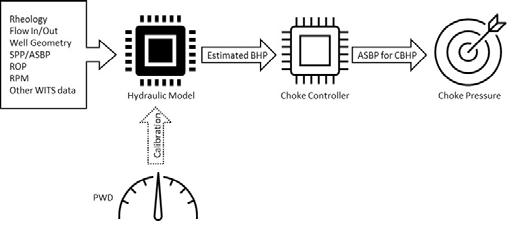
Figure 1. Conventional MPD workflow.
through the pump ramp transient period. This means that MPD connections may be simplified using a high-speed sampling of WDP downhole tools with measured downhole pressure feeding the choke controller directly, adjusting for time delays and depth offsets (Figure 3). Downhole pressure may be extrapolated from a single measurement and corrected with the assistance of the hydraulic model. This feature enables the choke to control directly from a sensor at or near the zone of concern rather than a sensor located up to five miles away.
WDP enabling downhole event detection
Coupling online hydraulic modelling with WDP presents significant advantages through downhole event detection in operations with MPD and WDP or in WDP standalone operations. One of the major drawbacks of contemporary event detection technology is that the data flowing into an algorithm is surface-acquired or single-point time delayed low-frequency data. Any alarms or automated functions are triggered with very limited direct knowledge of downhole conditions. While estimated hydraulic model data closely matches measured downhole data under normal conditions, actual downhole conditions may not match the model during contingency events.
Surface-based models may not match real downhole conditions during an influx if the gas enters the solution. A contemporary kick detection system will detect the influx when the flow out the well exceeds the flow coming in. In the solution gas case, however, the gas volume may not displace significant volumes of drilling fluid from the well, limiting the effectiveness of conventional kick detection systems. The entry of the solution of gas into the mud may continue undetected for several minutes until the gas saturates the mud and displaces it or the gas in the mud reaches the bubble point pressure.
Surface-based models may also not match real downhole conditions during a wellbore stability event. In a wellbore stability event, insufficient wellbore pressure may cause compressive failure of the wellbore to occur. Material from the borehole wall collapses into the well and is circulated out with the cuttings. The collapsed material has the same effect on average fluid density as cuttings do, leading to a cuttings load that is higher than modelled. The model only accounts for drilled cuttings; no such corrections are applied for collapsed material, and no surface change is immediately seen after a partial collapse. Kick detection systems are not designed to detect wellbore stability events; the value of a flow-out flow-in comparison is diminished because the volume of the collapsed material matches the void left by the collapsed material. Mass balance tools such as a Coriolis return flow meter are ineffective because the collapsed material is located downhole and is not detected until it is circulated to the surface.
Curiously, wellbore stability events can occur undetected in self-perpetuating cycles. Low wellbore pressure, the root cause of many wellbore stability problems, results in mixing collapsed
Review new trends and technologies
Download technical white papers for free from companies across the upstream industry


material with cuttings, increasing the average fluid density. The increased average fluid density temporarily mitigates the cause of the wellbore stability problem. Eventually, the collapsed material is circulated out of the well undetected, and the initial condition leading to the wellbore stability problem returns; the cycle repeats undetected while wellbore quality deteriorates.
Both in kick events and wellbore stability events, even the most accurate drilling models using surface-acquired data may not truly reflect downhole conditions.
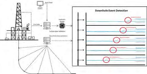
Combining WDP with MPD in a downhole event detection system significantly improves the rig crew’s visibility of subsurface events. As with contemporary systems, an online hydraulic model estimates drilling variables along the drillstring using surface-acquired data. The WDP enables the system to take measurements of the actual drilling variables along the drillstring. The downhole WDP measurements represent the downhole conditions as they are, whereas the estimates from the hydraulic model represent the downhole conditions as the rig control system can observe. This allows the downhole event detection system to directly compare measured values to expected values; a mismatch indicates an unexpected event or deteriorating downhole conditions, as shown in Figure 4.
In the solution gas kick case, the downhole event detection system may compare measured vs expected temperature along the string for early indications of a kick. Gas mixing heats or cools the drilling mud in unexpected ways. Comparing the measurement to the model allows the system to take along-string drilling fluid temperature deviation as an indication of a kick. This deviation may occur before solution gas reaches the bubble point, allowing the rig crew to act before a contemporary kick detection system sees a flow change. Notably, kick size is determined by inflow rate and event duration; by responding to a kick earlier, the rig faces fewer challenges circulating and reconditioning the well, saving time and cost.
In the wellbore stability case, the downhole event detection system may compare measured vs expected density along the string to indicate that a wellbore stability problem exists. Excess material falling into the well affects the average fluid density in unexpected ways. Along-string measurements pick up the density-changing effects of the drilled cuttings and collapsed material. Simultaneously, the hydraulic model accounts for the density-changing effects of the drilled cuttings but not the collapsed material. The resulting mismatch between the expected density and estimated density indicates an active wellbore stability event.
Other applications in downhole event detection include advanced visualisations. Advanced displays of the downhole event detection system show where the expected and measured values differ in time and along the well path. This allows a human to quickly determine where an issue is taking effect in the well to aid in the event response.
The next step
Detecting problems and responding to the well early is essential in reducing both costs and the occurrence of unplanned events. The industry is looking forward to taking the next steps toward autonomous drilling systems. Improved methods of fingerprinting and advanced downhole event detection allow operators to get drilling faster and respond to surprises sooner. Earlier characterisation of a problem allows the crew to form an appropriate response sooner, mitigating an event before it grows in magnitude and scope. Figure 2. MPD workflow incorporating WDP.
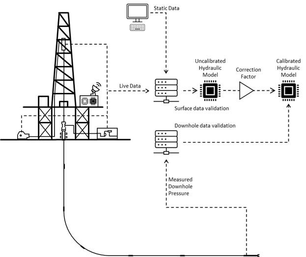
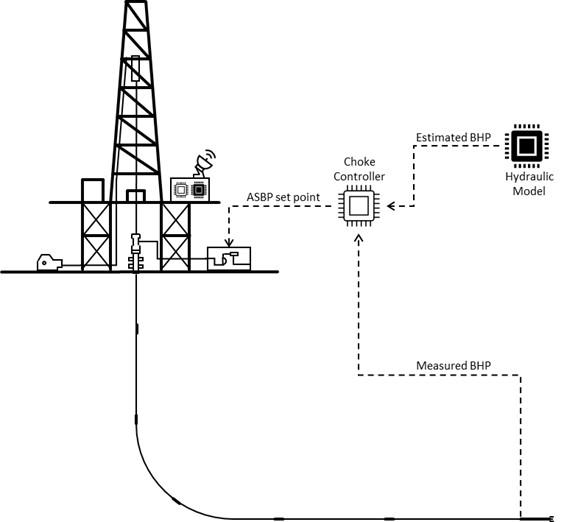
Figure 3. WPD integrated into MPD workflow enables choke control from direct measurement.
Figure 4. Combining MWD and WDP allows the downhole event detection system to compare measured vs. expected values.
Global Publication ENERGY GL BAL
The future is looking clean and green
