10 minute read
Advances In Acid Stimulation
Mojtaba Moradi and Michael R Konopczynski, Tendeka, UK, analyse the role of flow control devices in improving the performance of matrix acid stimulation operations in carbonate reservoirs.
The use of hydrochloric acid to stimulate oil wells began in 1932. However, effective matrix acidising stimulation of heterogeneous carbonates, especially across long intervals, has long been a challenge. This is because a sufficient chemical reaction rate to the rock is required to establish a controlled flow and deep-reaching penetration into the formation matrix without excessively increasing bottom hole pressure that can cause the formation to break down.1
The issues associated with acid placement in carbonate reservoirs are numerous: from dealing with a complex depositional environment to issues around the effect of dissolution, recrystallisation, and variable permeability caused by natural fractures, faults, low matrix permeability and formation damage from pre-production or production operations. Reservoir fluid properties including saturation, relative permeabilities and mobility issues, also influence the effectiveness of the stimulation.
The selection of stimulation fluid, diverters, pumping rates, treatment pressures, and the correct planning of the pumping schedule are therefore, all crucial to the effectiveness of the stimulation.

A new autonomous outflow control device
Addressing such complex reservoir properties and optimising the acid treatments for even fluid distribution along the wellbore can be problematic. For instance, thief zones, fractures, and hyper-reactive zones ‘stealing’ all the treatment and unsuccessful diversion for less conductive zones are culprits of inadequate and unoptimised acid stimulation.
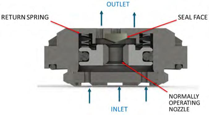
Tendeka has developed FloFuse, a new autonomous outflow control device, to provide mechanical diversion during matrix stimulation (Figure 1).
The active flow control device was initially designed to control the injectant conformance in injection wells, and could significantly help to improve the distribution of stimulation acid, especially in carbonate formations. As an injection rate-limiting technology, the device ensures proportional distribution of treatment
fluid along the full length of the wellbore and between laterals. It allows repeat stimulation of carbonate reservoirs, providing mechanical diversion without the need for coiled tubing or other complex intervention.
It has two operating conditions, one, as a passive outflow control valve, and two, as a barrier when the flow rate through the valve exceeds a designed limit, analogous to an electrical circuit breaker. The natural state of the valve, which is mounted into the base pipe or screen section, is in the open position (biased open).
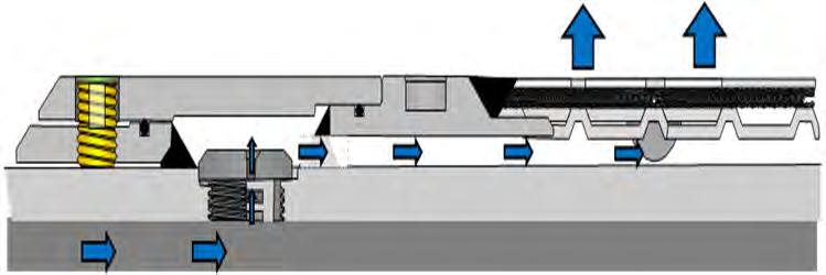
The injection outflow under normal operating conditions passes through the ‘normally operating nozzle’ and through the screen as required, as depicted by the blue baseline performance curve in Figure 2.
Once a zone has been sufficiently stimulated by the acid and the injection rate in that zone exceeds the device trigger point, the device in that zone closes and restricts further stimulation. Acid can then flow to and stimulate other zones. This eliminates the impact of the thief zone on acid injection conformance and maintains a prescribed acid distribution. The process can be repeated later in the well’s life to re-stimulate zones and can be retrofitted in existing completions or be used in a retrievable completion. As a spring-loaded valve, this trigger point can be altered based on the design parameters, including the nozzle diameter and spring constant.Figure 1. Cross-section of FloFuse valve, open position.

Figure 2. The fluid flow path through the device mounted on the screen and its housing.
Figure 3. The FloFuse valve performance for injection of water-like fluids.
Figure 4. Production profile before and after stimulation operation for Well A.


Dynamic response to acid stimulation
Conventionally, passive flow control devices, which are completions with a fixed configuration that influence the well’s outflow, have been installed in wells. If the well completion is not properly designed, its impact is less effective, especially if dynamic changes in reservoir properties happen which is often the case for a well with regular acid stimulation operations.
FloFuse restricts the injection of fluids into dilating/propagating fractures, faults, and features, thus mitigating disproportional injection, which could potentially reduce the performance of the operation.
If the devices are installed permanently as a part of a downhole completion in the well, the completion would be used to optimise the fluid injection, plus it could be used as a mechanical diverter for acid stimulation negating the need for intervention. It could also be installed temporarily as a mechanical diverter and retrieved once the stimulation is finished. With either solution, acid could be bullheaded from the surface.
Several experiments including water, polymer and air injection have been performed to characterise the valve. The characteristics could be described for example by the curve of differential pressure drop (DP) across the device against flow rate passing through.
Figure 3 represents the performances of different sizes of devices namely: 2.2 mm, 3 mm, and 4.5 mm, for water-like fluids.
Modelling and operational design workflow
Once the completion is installed and acid bullheaded from the surface, FloFuse allows acid injection while controlling the flow of acid into higher rate intake (permeability) zones. Thereby, ensuring effective fluid placement across the whole length of the wellbore being treated initially, while each discrete zone is effectively acidised. As the volume of acid and injection rate is important in carbonate acidising to get the appropriate wormhole, this concern should be included in pump rate planning.
Once the FloFuse completion nominal design has been completed, additional sensitivities can be run to evaluate the impact on production or injection profiles from changes in the simulation treatment design. In addition, an understanding of the mechanisms that may cause deviation from the planned acid injection rates and distribution should be noted. Ultimately, the treatment design needs to be confidently executed in the field as per the design plan.
Well A, located in the Middle East, passes through four main reservoir layers. It has been extensively studied and the pumping schedule and post-evaluation study of the real stimulation operation are provided.2
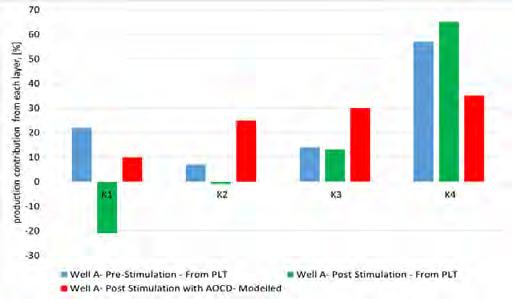
During pre-stimulation conditions, the well could only produce 25 MMScf/day of gas with a wellhead pressure of 3400 psi. Also, the contributions from the layers are non-uniform and zones 4 and 1 produce almost 51% and 32% of total produced gas respectively, while the other two zones’ share is only 17%.
The post-evaluation study shows that although the bottom layer was treated , the top layer may have been overtreated as evidence shows the existence of crossflow inside the tubing (Figure 4). This is mainly due to heterogeneity in the layer’s properties including skin, permeability, and reservoir pressure.
A static wellbore model was set up using a commercially available software. The result from the model, which agreed with the output of PLT data taken pre-stimulation, showed that more than 51% of gas was produced from layer K4 when assuming the gas production rate is 25 MMSCF/D. To investigate the impact of a new diverter (completion) on the acidisation performance for this well, a retrofit FloFuse solution was evaluated.
This was comprised of four completion zones separated by four annular flow isolations placed at the border of layers. Devices are mounted on 5.5 in. joints to be retrofitted inside the current completion. For this example, the use of 4.5 mm FloFuse devices which close at a DP of 200 psi is recommended.
The assumed objective was to stimulate the well to significantly enhance production from low productive zones while reducing the formation damages at higher productivity zones.
At the outset, an acid injection rate of 15 bpm was modelled. Due to the impact of the FloFuse devices on flow profile, the acid intakes of the zones are more balanced compared to the base case well scenario. For example, the contribution from zones 2 and 3 has increased to 28% compared to 17%, even at the beginning of the process. However, layer 4 is expected to still take most of the fluid (51%) at this stage. Here, it is assumed that the acid will be stimulating layer K4 more rapidly and to a greater extent, compared to other layers. At this stage, it is assumed that once the skin value decreases to 20% of the initial value, the stimulation of the layer is sufficient and the FloFuse devices should close.
The reduction of skin at each layer is associated with a higher intake of acid from that layer. Once the new skin value for the layer is established, the DP across the devices reaches the trigger point and the valves at this zone are tripped (closed).
To move to the next stage, the operator should always consider the impacts of the closed valves on the DP across open devices to avoid premature closure of valves at other zones. Here, it was decided to lower the injection rate to 14 bpm to avoid this, most notably, at zone 1, increasing the margin of DP from the closing pressure of 200 psi to allow sufficient stimulation. If more time is required to inject a sufficient volume of acid to reach the desired skin, the injection rate should be lowered further.
Once the skin value decreases to 50% of the initial value, the valves at this zone would also close, so the acid would be diverted to zones 2 and 3, which had the lowest contributions initially.
Considering the number of closed valves, as well as the results of earlier stages, lowering the injection rate to 12 bpm is necessary to remove damage from these zones completely without any valve closing.
Once the new skizns are established, the operator could decide to stop the operation or reset the valves to open positions and perform another stage of stimulation, if further stimulation is required. For instance, once all valves are open, the new profile which is a more balanced profile with higher contribution from zones 2 and 3 is achieved. Please note that the required time to establish the new skin at each stage is not considered in this study and could be estimated using available software.
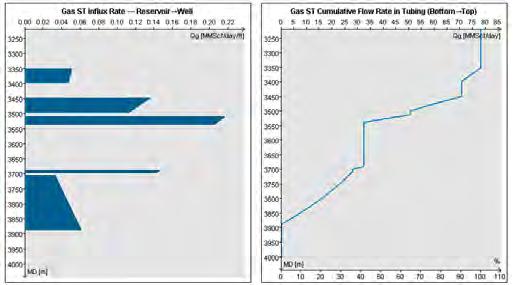
The results from post-stimulation modelling, as shown in Figures 5 and 6, illustrate the success of FloFuse completion to improve the acidisation operation of the well.
The data not only shows that a more than threefold increase in production rates (78MMSCF/day) from the well stimulated using FloFuse diverters could be achieved, but also that the new production profile from the well is more uniform and no crossflow between the layers is observed.
References
1. HARRISON, N. W. “Diverting agents - history and application”. Journal of
Petroleum Technology, 24 (5) (1972) pages 593–598. SPE-3653-PA. https://doi. org/10.2118/3653-PA 2. SAFARI, ALIREZA R; PANJALIZADEH, HAMED; POURNIK, MAYSAM; JAFARI,
HAMED AND ZANGENEH, ALIREZA. “A comprehensive method for diverterperformance evaluation during stimulation of long-interval heterogeneous reservoirs: A case study”. SPE Prod & Oper 36 (2021) pages 22–33. doi: https://doi. org/10.2118/200135-PA 3. HALL-THOMPSON, BRYAN; ERNESTO, ARIAS ROMMEL; ABDULRAHMAN, NUTAIFI;
AND ABDULAZIZ ALSUHAIMI. “Acid stimulation - best practices for design, selection and testing of acid recipes in low permeability carbonate reservoirs”. Paper presented at the International Petroleum Technology Conference, Dhahran,
Kingdom of Saudi Arabia, January 2020. doi: https://doi.org/10.2523/IPTC-19690-MS 4. HALL-THOMPSON, B; ARIAS R.E; UTAIBI A.A; AND MASHAT B. “Extending technology l limits – successful application of multi-stage open hole horizontal completion in offshore environment”. SPE 188712-MS presented at the Abu Dhabi International
Petroleum Exhibition & Conference held in Abu Dhabi, UAE, 13-16 November 2017 5. MOHD ISMAIL, ISMARULLIZAM; KONOPCZYNSKI, MICHAEL; AND MOJTABA MORADI.
“A game changer for injection wells outflow control devices to efficiently control the injection fluid conformance”, Paper presented at the Abu Dhabi International
Petroleum Exhibition & Conference, Abu Dhabi, UAE, November 2019 doi: https:// doi.org/10.2118/197612-MS 6. MORADI, MOJTABA; ZAREI, FARAJ; AND MORTEZA AKBARI. “The improvement of production profile while managing reservoir uncertainties with inflow control devices completions”. Paper presented at the SPE Bergen One Day Seminar, Bergen,
Norway, April 2015. doi: https://doi.org/10.2118/173841-MSq

Figure 5. Production contributions from each layer for different scenarios.
Figure 6. Predicated production profile from Well A: post-stimulation.


