14 minute read
Sulfur Storage Tank Challenges: Part One

SULFUR STORAGE TANK CHALLENGES:


PART ONE
In the first part of a two part article,
Brandon Forbes and D.J. Cipriano, AMETEK/Controls Southeast Inc.,
USA, highlight the challenges that arise from the storage of sulfur and show how a well-designed and installed thermal management system can counter these problems.
There are several unique challenges associated with storing sulfur in fi eld-erected tanks. The most signifi cant challenges are those related to safety and those related to maintenance. Over the last decade, sulfur tank safety concerns have become more widely considered, with more publications describing the concerns. The primary safety concerns are as follows:
Accumulation of hydrogen sulfi de in the tank vapour space – explosion and exposure
Sulfur produced via the modifi ed Claus process will contain high levels (up to 500 ppmw) of dissolved and chemically integrated hydrogen sulfi de (H2S). Unless the sulfur goes through an additional degassing process, it will slowly release the H2S into the vapour space as a gas. The lower explosion limit (LEL) of H2S gas mixed with air is roughly 4 vol% (though it changes with temperature and other factors). Additionally, H2S in air is lethal at concentrations as low at 500 ppm. It is therefore critical that the accumulation of H2S gas in the tank vapour space be addressed.



Providing the tank with an inert vapour space (e.g. a nitrogen blanket) is one method of addressing the LEL concern. However, this method still allows a signifi cant build-up of H2S gas to accumulate. This build-up could present an explosion hazard if oxygen (air) were to be inadvertently introduced; it could also present a health hazard if the vapour were to be inadvertently released. For these reasons, and other reasons described later, a continuous sweep of ambient air is the preferred method of handling the tank vapour space.
The required rate of sweep air is calculated based on the sulfur turnover rate in the tank, the maximum resulting H2S release rate and the vapour turnover rate required to stay below the 4 vol% LEL. Excessively high sweep rates should generally be avoided as they place a signifi cant heat load on the tank, which can lead to sulfur freezing and blocking nozzles/vents as well as corrosion – both of which can result in additional safety hazards.
This sweep air arrangement can be implemented in one of two forms: a ‘forced sweep’ uses an ejector or blower to move air through the tank and deliver it to a safe location for release or processing. A ‘free convection sweep’ uses strategically located vents to induce a draft that pulls air through the tank and releases it from a vent in the roof. Free convection sweep is typically preferred where the sulfur is expected to have minimal H2S content. Forced sweep is typically used where the sulfur is expected to have high H2S content and the exhaust vapour must be treated for health, safety and environmental (HSE) reasons.
A fi nal point regarding H2S accumulation is the need to avoid ignition sources. Sulfur has a relatively low electrical conductivity and can therefore build up a static charge – especially if it is allowed to freefall. The use of a dip-tube is recommended where sulfur is supplied from a roof nozzle. A second common ignition source is various forms of pyrophoric iron sulfi des.
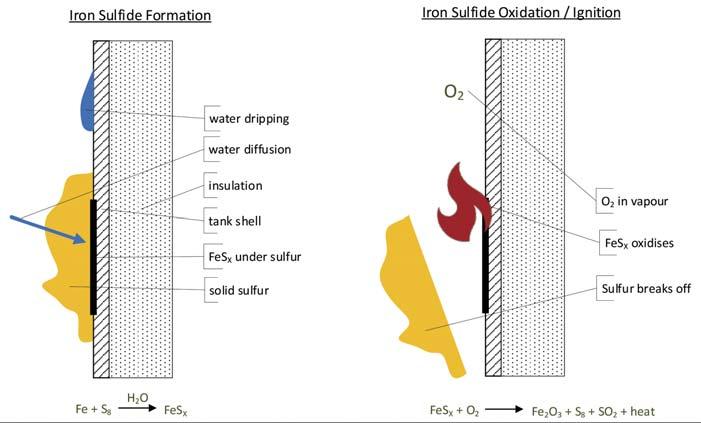
Figure 1. Iron sulfide ignition mechanism.
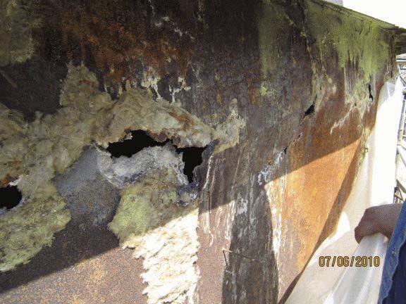
Figure 2. Example of sulfur tank shell corrosion.
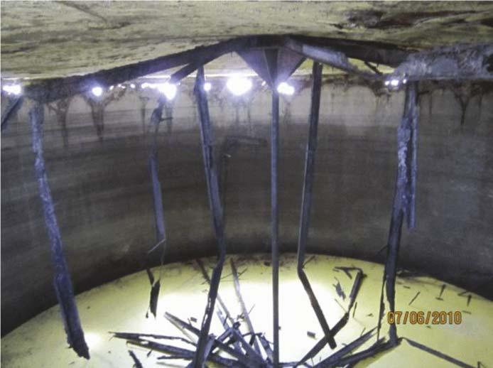
Figure 3. Example of sulfur tank structure corrosion.
Accumulation of pyrophoric material – fi re and explosion
When combined, sulfur, steel and water react together to form various iron sulfi des. These sulfi des are pyrophoric – when exposed to oxygen, a rapid exothermic oxidisation reaction occurs. With a suffi cient mass of accumulated sulfi des, the temperature resulting from the oxidation reaction can be high enough to ignite H2S in the vapour space or ignite the sulfur itself. To avoid this scenario, either the accumulation of sulfi des or the oxidation of sulfi des must be prevented.
One method of preventing the formation of iron sulfi des is to maintain all carbon steel surfaces above 100˚C (212˚F) to prevent the accumulation of liquid water. The presence of sulfur can frustrate efforts to this end, as solid sulfur that builds up on the interior surface insulates the wall and drives down the temperature. Water vapour can penetrate the porous sulfur, condense at the wall and form iron sulfi de. Worse still, iron sulfi de formed in this manner can accumulate in large masses that are only exposed to oxygen when chunks of sulfur fall away from the wall. These large masses of sulfi des reach very high temperatures when they suddenly oxidise together.
A better approach is to maintain all carbon steel surfaces above 120˚C (247˚F) to prevent sulfur from freezing. This prevents the formation of iron sulfi des. Even if some small cold spots exist, without large sections of solid sulfur accumulation it is unlikely that large masses of iron sulfi de will form. Small masses of iron sulfi de not buried under frozen sulfur are typically not a problem. They tend to oxidise as they form and never reach the critical mass needed to achieve dangerously high temperatures.
One might attempt to stop the iron sulfi de formation by removing water from the system. Unfortunately, this


Weighcont Blender

* Capacity of 20 to 200 ton per hour. * Unlimited number of hoppers. * Computer controlled. * Custom built. Fertilizer Inhibitor Treating Unit
* Portable. * Stainless steel. * Computer controlled. * High Capacity 120 m³ per hour.
EMT
Molenpad 10, 1756 EE ‘t Zand The Nederlands. Tel.+31 (0) 224 591213 email: emt@emt.tech www.emt.tech
High Speed Bagging Line
* For big bags - jumbo bags. * Capacity 50 to 70 ton m³ per hour. * 120 kg to 1250 kg bags. * Suitable for granular and powder materials. * Available with dust reducing system.
Shamrock Blender
* Capacity of 25 to 70 ton/m³ per hour. * Machine size 4,5-5,4-7-9-11,5-14 ton. * Easy and gentle blending process. * Blending and weighing are separated.
Doyle Equipment Manufacturing
1 Jack Doyle Industrial Drive, Palmyra, MO. 63461 USA. Tel. +1(217) 222-1592 & +1(573) 300-4009 doyle@doylemfg.com, www.doylemfg.com
Global coverage of the fertilizer industry
• International fertilizer news • Regional reports • Market analysis • Event previews and reviews • In-depth technical articles • In-depth regional analysis by key players in the industry • Comprehensive technical reviews covering all aspects of fertilizer production, from plant optimisation and automation to blending, bagging, and dispatch

approach is not likely to succeed, as there are numerous potential water sources, including: Leaking internal steam coils. Inadequate vent caps. A damaged tank roof or nozzles. Humidity in ambient air. Oxidation of H2S where: H2S + O2 → H2O + SO2 Rust-catalysed breakdown of H2S where: H2S + O2 → S8 +
H2O + SO2 (note this is highly simplified as there are several reaction steps with several intermediate iron oxide [FeOX] and iron sulfide [FeSX] molecules). Use of snuffing steam.
Use of an inert vapour space (e.g. a nitrogen blanket) will prevent the ignition of iron sulfi des. However, this is generally considered to carry signifi cant risk, as without oxygen any sulfi des that do form will accumulate over time. When the nitrogen blanket is removed (intentionally or unintentionally) and oxygen enters the tank vapour space, there may be a very large mass of accumulated sulfi des available; these will likely burn at a very high temperature, increasing the risk of a tank fi re. Using an ambient air sweep will tend to oxidise the sulfi des as they form, via the mechanism described above, and is generally considered the safer approach.
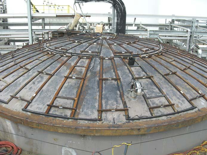
Figure 4. Example of tank roof heating.
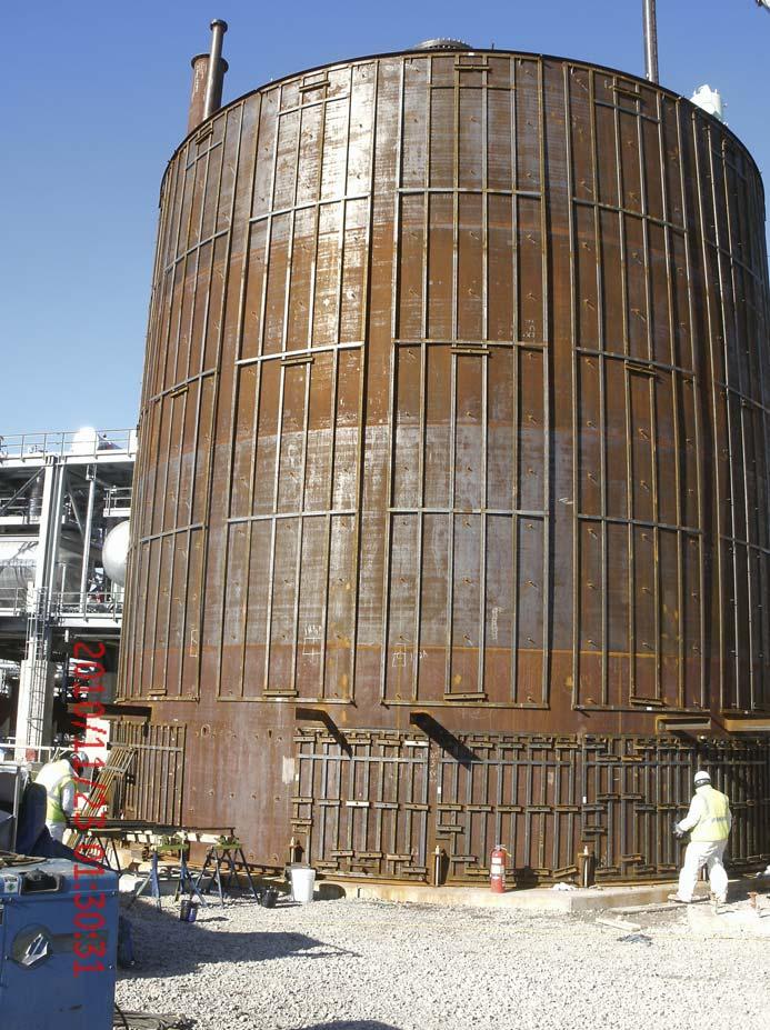
Figure 5. Example of tank shell heating.
Safety summary
While each sulfur tank application should receive a specifi c review, the following high-level recommendations should be considered for any sulfur tank application: Sweeping the vapour space with ambient air is generally preferred over an inert blanket. The sweep rate must be high enough to prevent the concentration of H2S from reaching the LEL. The sweep vapour must be handled in a way that does not present an HSE concern. The tank should be heated in such a way that the formation of iron sulfides is prevented or severely limited. The sweep air system (including tank nozzles) should be heated in such a way that prevents plugging.
Tank corrosion
The primary challenges to sulfur tank maintenance are corrosion and plugging. Problems with plugging are immediately evident and can be addressed with adequate heating. Problems with corrosion can progress undetected, however, and result in extensive damage as well as potentially hazardous material release events. There are several different corrosion mechanisms that can contribute: Internal corrosion can occur due to the iron sulfide reaction described above. This generally occurs in the vapour space and can occur rapidly. Internal corrosion can also occur in the more conventional manner due to the presence of water.
Common sources of water are as discussed earlier. External corrosion can occur due to ambient water exposure. This mechanism is not unique to sulfur storage.
Water that penetrates the insulation may sit against the external tank surface for an extended period, as evaporation from under the insulation will be slow.
Field-erected storage tanks are also subject to water intrusion into the space between the tank bottom and the concrete pad (or ring-wall). Again, evaporation from this area will be slow and significant corrosion can result. External corrosion can occur due to spilled sulfur. There are several mechanisms by which spilled sulfur can accelerate the corrosion of steel surfaces. Mixing sulfur and water can generate small amounts of sulfuric acid that eat through the steel. Together, sulfur, water and steel can react to decompose the steel and form iron sulfides, as described earlier. Finally, thiobacilli bacteria can also produce sulfuric acid as they digest the sulfur. Sulfur tends to accumulate around the tank vents and on the ground at the base of the tank; these are the areas that tend to be most susceptible to this form of corrosion.
Controls Southeast Inc. (CSI) has developed a tank heating technology utilising ControTrace engineered bolt-on jacketing. The system uses a distributed heating arrangement that provides uniform heating to the entirety of the tank shell and roof surfaces. Nozzle and instrument heating can also be provided. The goal of the design is to resolve multiple safety and reliability concerns by addressing the various root causes: Prevent H2S accumulation in the vapour space by heating of the vent nozzles. This prevents sulfur solidification in the nozzles that could restrict or block the vapour flow. Prevent iron sulfide formation by maintaining the shell and roof above 120˚C (247˚F) at all locations. This prevents sulfur solidification and water condensation, which in turn prevents iron sulfide formation. Prevent plugging of nozzles by providing direct heating. Prevent corrosion by maintaining the tank wall and roof temperature. Preventing water and sulfur condensation on the tank surfaces effectively blocks the corrosion mechanisms described previously.
Additionally, the ControTrace external heating system provides heat directly to the liquid sulfur in the tank. This removes the need for internal coils, subsequently eliminating costly coil maintenance and potential water intrusion into the tank.
The heating system is comprised of multiple heating panels, each made up of multiple individual heating elements. The heating elements are spaced at a specifi ed distance that maintains the tank wall temperature above the target temperature (typically 125˚C) at all locations. Additionally, the panels themselves are shaped to fi t closely together and to wrap closely around nozzles and other tank protrusions. In this way, all locations on the tank shell and roof are maintained above the target temperature.
Maintaining the liquid sulfur temperature typically requires additional heat input to offset the heat loss into the ground. The heating panels located near the bottom of the tank typically use more dense heating elements to provide this additional heat. This is especially critical when the liquid level is low and the liquid contact area with the heated tank wall is reduced.
CSI determines the heating system design and predicts the tank temperatures by utilising a proprietary fi nite-difference model. The model accounts for all relevant heat paths to determine both the liquid and the vapour temperature in the tank. In addition, the model calculates the tank shell and roof temperature profi le based on a given ControTrace element spacing. In this way, not only is the sulfur temperature maintained, but a uniform shell and roof surface temperature is as well. The company’s thermal model was developed using computational fl uid dynamics (CFD) modelling to verify uniform sulfur temperature distribution within the vessel. The model has been validated with detailed fi eld temperature measurements including infrared imaging.


Dry granulation of fertilizers
Our technology has been recognized around the world for dry granulation of MOP / SOP and NPKs. Our services cover pilot plant tests, basic engineering, equipment supply, start-up supervision, and commissioning. Typical fl ake capacities are in the range of 10 –130 t / h or more.
We have received orders for more than 0 fertilizer compactors of latest Köppern technology since the year 2000. The total installed fl ake capacity of these plants is exceeding ,000,000 tpa. Köppern – Quality made in Germany.
• State of the art technology • Process technology know-how • High plant availability • Quick roller replacement

Figure 6. Tank model macro-level heat transfer accounting.
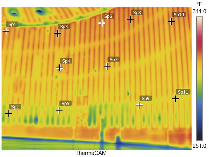
Figure 7. Thermal image of ControTrace-heated sulfur tank interior.
With each panel custom-fabricated for the application, the ControTrace heating system has several advantages: The element spacing and panel locations are fixed, meaning the wall temperature is assured at all locations. Each panel is an independent unit attached to a predetermined location on the tank, thus removing any guesswork and minimising the labour required to install the system. Panels are arranged in columns with a single steam circuit per column, thus minimising the number of circuits and required steam infrastructure.
Conclusion
As discussed, the storage of sulfur creates a number of challenges for any facility. The accumulation of H2S and pyrophoric material (e.g. iron sulfi des) can lead to serious consequences if not properly mitigated through tank design and temperature control. A few best practices for these were discussed.
Part two of this article will show how a team at a working facility in the Gulf Coast, US, successfully met these very challenges. Previous sulfur tanks in the facility experienced signifi cant corrosion. A tank commissioned in 2006 incorporated the best practices discussed above. A recent detailed inspection revealed the strengths and weaknesses of the new design approach. Their fi ndings and lessons learned will be presented.
Bibliography
1. CLARK, P.D., HORNBAKER, D.R., and WILLINGHAM, T.C., ‘Preventing
Corrosion in Sulfur Storage Tanks’. Paper presented at Brimstone
Sulfur Symposium 2008, Vail, Colorado, US, and British Sulphur 2008,
Montreal, Canada. 2. AFPM, ‘Process Safety Bulletin – Flammability Hazards of Hydrogen
Sulfide Accumulation in Sulfur Tanks’, June 2018.
Stay informed
Keep up to date with us to hear the latest World Fertilizer news
