
7 minute read
Earning Its Stripes

Gelmer Bouwman and Geoffrey Havermans, Kreber, the Netherlands, investigate how computer-aided design has become a key tool in the design and optimisation of prilling facilities.


In 1918, the physicist and Nobel Laureate Hendrik Antoon Lorentz started the calculations needed to build the Enclosure Dam in the north of the Netherlands. Eight years later, in 1926, his full recommendations containing complex mathematical calculations regarding tides, river flow, wind power and storm predictions – all made without calculators – were published (Figure 1).1 We have come a long way since then. Nowadays, the computational power of computers is readily available even to the non-physicist, enabling highly complex situations to be analysed in a fraction of the time. Computer-aided engineering (CAE) is also playing an indispensable role in the design of prilling towers. This article will highlight the four application areas where CAE is taking a leading role.


Firstly, computational modelling provides comprehensive sets of data that are not easily obtained from experimental tests. Experimental testing can be demanding owing to the development of a test set-up and the purchase of instrumentation. In some cases it might be difficult or even impossible to find suitable instrumentation to collect the desired data. In Kreber’s experience, computational modelling reduces the demand for complex experiments. Two research problems, for which the company uses CAE, will be discussed more elaborately.
The first example of such a problem, where computational modelling provides a solution, can be seen in company research into rotary prillers, which are at the heart of the prilling process. Hot melt is fed into the rotary prillers, which consist of perforated buckets. By rotating the bucket, the liquid melt forms a vortex and, due to centrifugal forces, the liquid melt leaves the bucket and forms molten droplets. This process of vortex formation, jet break-up and consequent droplet formation is difficult to analyse within an operational tower, as it is difficult to record data on the prilling bucket. The prilling bucket is a fast-rotating piece of heavy machinery with little space for sensors. Furthermore, modifying the prilling bucket to allow mounting of sensors is not desirable, because the experimental conditions should ideally replicate those experienced within the industry and by the end user.
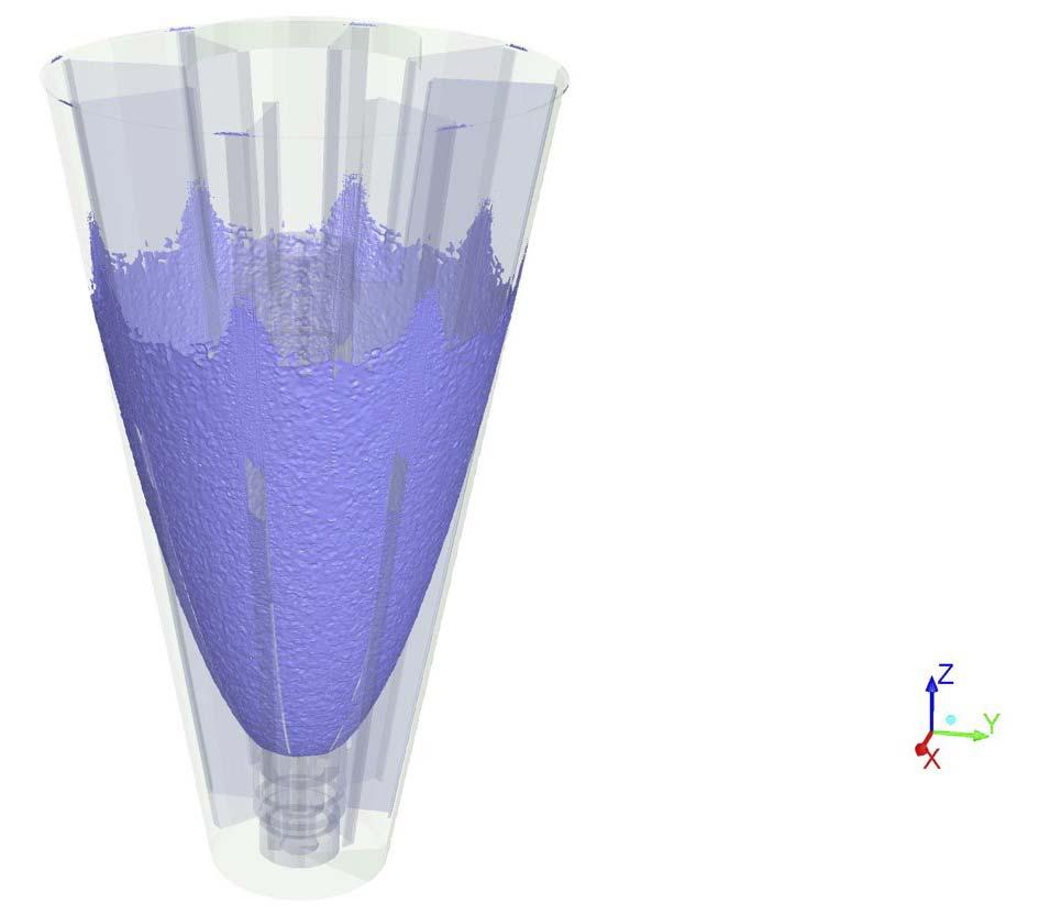
Computational fluid dynamics (CFD) simulations can be performed to gain a better understanding of the internal dynamics of these rotary prillers. The findings of these simulations (Figure 2) are used to validate an exact mathematical model and can be applied to any newly developed priller to investigate internal flow behaviour. The use of CFD helps to greatly limit the number of iterations from concept to functional product.
The second problem is the jet break-up, which is hard to research up close. CFD provides a solution, and the results of a simulation are shown in Figure 3. Most experiments for jet break-up can be performed on a laboratory scale, where a vertical jet is analysed and possibly perturbed. In rotary prilling buckets the jet is curved, and the jet shape affects the way droplets are formed. It is possible to produce a spinning device where hot melt leaves a nozzle and analyse the droplet formation, but this direction is labour-intensive and difficult.
CFD can also be applied in this situation. It is possible to investigate any type of melt-based fluid characteristics, which are typically the viscosity and surface tension. Both are a function of temperature, and it can be observed that rapid fluctuations in temperature swing could lead to an improved jet break-up: an interesting phenomenon, even though this cannot be utilised at an industrial scale. The company currently uses pressure fluctuations to improve jet break-up. CFD shows that there is a discrepancy between the optimal frequency as calculated with standard formulas and the modelled values. This is a key insight that Kreber are keen to investigate on an industrial level. Industrial trials are scheduled for later this year.
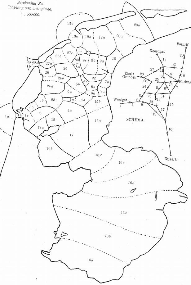
Figure 1. Layout of the northern part of the Netherlands, where the water is divided into sections for the purpose of calculating flow from one section to the other.1
Figure 2. CFD simulation on vortex formation inside rotary priller.
At the push of a button
Secondly, employing CAE results in a reduction of engineering time. Recurrent calculations, as highlighted in the work by Lorentz, can be time-consuming.
Modelling is most valuable when carrying out repetitive calculations.
The basic designing of a prilling tower is highly repetitive. Based on the physical material properties, the desired prill size and production capacity, it is possible to give a first estimate of the prilling tower. The values of the parameters change for each design, but the calculations remain the same. Since the company have employed a computational model for the tower, a new design can be made with the push of a button. Previously, such design calculations took multiple weeks; nowadays it takes half an hour. Kreber have performed numerous tower design calculations over the past decades, saving a considerable amount of time.
Digital twin
Thirdly, CAE has the predictive power to find optimal operational setpoints. In operation, stringent production targets are in place, which makes it hard to experiment with setpoints. As changing setpoints often results in changes in flow behaviour and possibly lower production, trying to find optimal settings is expensive. Using a digital model of a process allows for optimisation of the process without loss of production capacity.
In prilling towers, the prill outflow as a function of time is an interesting case to highlight. The case discussed here concerns the prill outflow fluctuations from a prilling tower that has a rotating prilling bucket, scraper and conveyor belt. The flow rate depends on the bucket type and its rotational velocity, the scraper design and its velocity and the conveyor belt speed. A resulting image of this modelling can be seen in Figure 4.
The possibility to experiment with setpoints and train operators is often referred to as the digital twin and is a good example of the value of CAE.
Reducing uncertainty in new designs

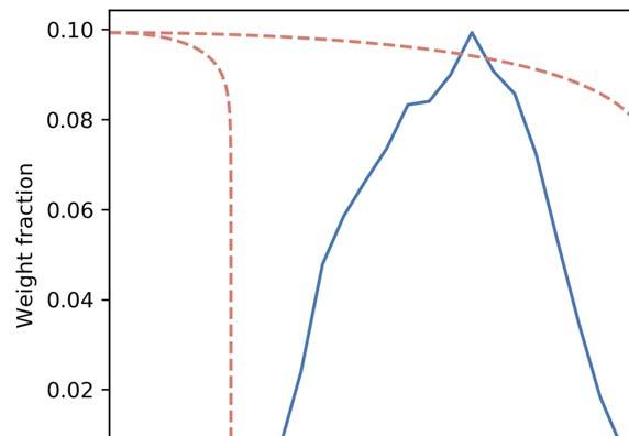
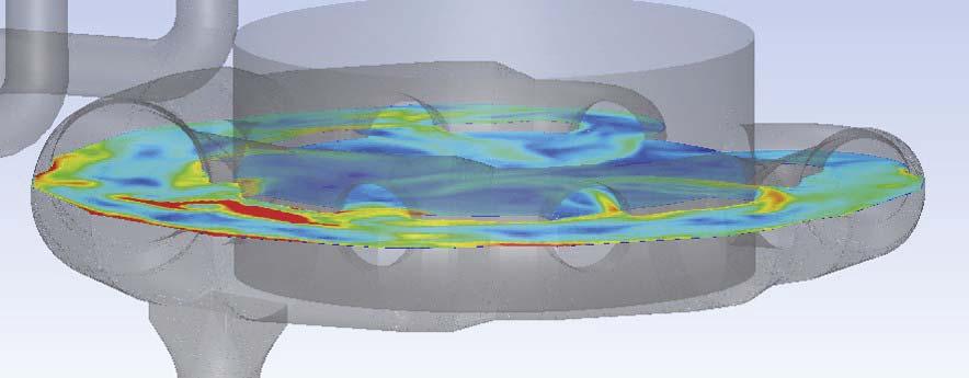
Finally, CAE provides data for new designs when experimental data is unavailable. Validating a new design can be an expensive affair, especially in the iterative design phase when a large number of resources are required. CAE can reduce uncertainties and limit the number of design iterations prior to the production of valuable equipment. Kreber has experienced the capabilities of CAE when designing a closed-loop prilling facility. In a closed-loop Figure 3. Jet formation and subsequent droplet formation of a spiralling jet. configuration, the cooling air is recycled by closing the loop and adding a heat exchanger. The cooling gas is forced through the heat exchanger and into the tower by employing a fan. A ring duct design is required to create an even distribution of air flow in the tower. The uniform air flow distribution results in efficient operation of the prilling process, which means the ring duct design is important. The design of such a ring duct might seem trivial on paper, but several design iterations and CFD simulations were needed before a satisfying design was reached, resulting in an well-distributed air flow (Figure 5). Figure 4. Graph indicating the weight distribution of prills at the bottom of a prilling tower. This graph is the result of prills trajectory calculations. Figure 5. Visualisation of fl ow inside closed-loop ring duct for one of the iterations during the design phase.

The thrill of the perfect prill
CAE has more than earned its stripes in the prilling industry and it will be a vital instrument in the journey to achieve the perfect prill. The continuous development in computational power, improved accessibility and research endeavours will continue to provide a valuable contribution to the development of prilling technology and services.
Reference
1. Lorentz, H, A.,Verslag van de Staatscommissie
Zuiderzee (1926).


