
8 minute read
Linking up digital technologies



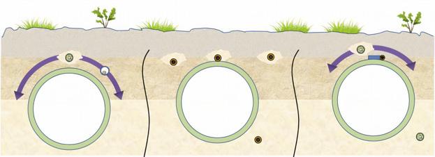
Figure 3. Proper fibre positions for DAS (left), DSS (middle) and DTS (right).
Table 2: Fields of use and applications of different DFOS technologies at pipelines
Field of use Application DAS DTS DSS
Condition monitoring Leak detection (single phase, multiphase, subsea)
Third party interference Intrusion +
Perimeter security +
Hop tap theft +
Valve theft / operation +
Geo-technics Earthquake +
Rockfall +
Soil erosion + +
Subsidence +
Process monitoring Landslip + +
Pig tracking +
Slack line +
Process monitoring Slug profiling +
Strain +
Deformation +
Trace heat Heat trace monitoring +
or heating element and sensitively detects any location with insufficient heating.
In one application, four sulfur transport pipelines with a total length of 76 km required monitoring. High temperature optical cables - rated to 250˚C and capable of withstanding the demands of heating and cooling cycles - were installed with multiple DTS systems to enable redundancy and to accurately measure the temperature to within 1˚C along the full length of the pipeline with 1 m spatial resolution. Smart software clearly displays temperature conditions along the pipelines and sends alarms on pre-defined conditions to the operator so they can make well informed decisions.
DFOS can also be used for the forensic post-analysis of events. In one example, a pipeline operator was running pigs through a pipeline and experienced an issue: a magnetic cleaning pig had lost several large magnets somewhere along the pipeline. Typically, a pig generates a characteristic signal as it passes across joints in a pipeline. Forensic inspection of these signals along the length of the pipeline allowed identification of where the magnets had come loose from the pig – through the observation of an additional signal component – and ultimately to identify where the magnets had been dropped when this additional signal disappeared. The pipeline operator was informed and found the magnets at the location identified.
Fibre installation As already mentioned, DFOS requires only a fibre-optic cable installed alongside the pipeline for continuous monitoring of the whole route. Optimum location and installation method of the cable depend on the interrogation method and sensing requirements. It is of course simpler to factor fibre installation in for new pipelines, but it is possible to retrofit fibre or utilise pre-existing fibre on older pipelines.
The optimal position of the fibre with respect to the pipeline depends on the DFOS method and the application (Figure 3). For DAS on buried pipelines, a fibre position slightly above the centreline of the pipeline provides good sensitivity for leak detection as well as for third party intrusion. The fibre should also be buried for mechanical protection.
For DSS, the fibre needs to be installed at the place where strain is to be monitored. A fibre attached directly to the pipe will detect pipe strain and bending. If the fibre is buried in soil in the vicinity of the pipe, DSS monitors ground movements.
For DTS, the optimum fibre position for thermal leak detection depends on the fluid. Liquid seeps down through the soil and therefore the fibre should be placed somewhere below the pipe. However, gases expand upwards and a fibre above the pipe is better suited for gas leak detection. For heat trace monitoring by DTS, fibres are directly attached to the pipe or the heating element.
For exposed pipelines, fibres should be directly attached to the pipe and protected from environmental effects such as direct sunlight or wind to ensure optimum performance in the application.
Conclusion DFOS is a powerful, maturing technology that enables permanent and efficient monitoring of long pipelines and associated infrastructure. Thanks to its continuous monitoring, DFOS provides a vital layer of additional intelligence, able to detect and to pinpoint the location of multiple threats simultaneously. DFOS requires only an optical fibre to provide readings from thousands of locations along the entire route of a pipe. DFOS is a reliable, safe, secure, economical and scalable technology with multiple fields of use at pipelines, enabling operators to accurately monitor their pipelines to protect their assets and improve safety.
Note FOSA would like to thank the following contributors: • Kent Wardley, VP Sales, Americas, Fotech/Chair, FOSA. • Pedro Barbosa, Product Owner, Fotech. • Chris Minto, Engineering Director, OptaSense. • Alasdair Murray, Senior Analyst, OptaSense. • Wieland Hill, Director Advanced Sensing, NKT Photonics/ Chair, FOSA Technology Committee.


Matt MacDonald, Fotech, a bp Launchpad company, reviews how advanced distributed acoustic sensing technologies incorporating machine learning support digitalisation of pipeline operations.
Pipeline operators are under increased pressure to improve efficiencies, reliability and safety. Digitalisation – whereby digital technologies seamlessly connect together to advance processes throughout an organisation – is widely regarded as the way forward for oil and gas companies to realise these demands. One area that enables digitalisation is the use of advanced sensors for pipeline monitoring. There are various reasons why pipeline networks are monitored, for example, for detecting leaks or third-party interference and theft 'hot tapping'. However, regardless of the application, operators want confidence in their monitoring technology and assurance that it will perform to the highest levels, providing high accuracy, and with reduced false alarm rates They also need to be able to respond quickly to any threats. Distributed Acoustic Sensing (DAS) technology is key to achieving this.


The need for smart sensors The Colonial Pipeline leak incident in 2020 is a stark reminder of just how important pipeline monitoring is and why improved smart sensing is essential. When the US’s largest fuel pipeline leaked, at least 1.2 million gallons of fuel spilled into a nature reserve. It is thought that the leak went undetected for weeks without operators realising. It wasn’t until some local residents found a puddle of gasoline that the alarm was raised. Clearly, operators need reliable leak detection systems that will raise alerts fast.
There are many types of existing monitoring and leak detection technologies available based on internal systems. For example, some use pressure and flow readings from supervisory control and data acquisition (SCADA) systems. There are also mass balance and real time transient modelling (RTTM) and sophisticated computational pipeline management (CPM) systems, which use metering and complex calculations. However, as these systems infer a leak by computing, they tend to have long detectability times and very low sensitivity to small leaks.
Furthermore, existing leak detection systems don’t detect most spills. A 2012 study found that when pipelines had detection technology in control rooms, they flagged leaks about 28% of the time. Systems with CPM detected about 20% of leaks. Overall, PHMSA data shows more than 4000 spills on oil and fuel pipelines since the start of 2010, but leak detection systems identified only about 7%.1
Incorporating advanced sensing technologies such as DAS can help transform pipeline operations by more quickly and accurately identifying incidents.
Discovering DAS DAS technology is a modern smart sensing system that uses fibre optic cables that run adjacent to a pipeline network, and it is proving itself as an accurate method for pipeline monitoring. It is currently deployed on thousands of kilometres of pipelines worldwide. Compared to more traditional techniques it provides continuous monitoring 24/7, over long distances of up to 100 km, and it can detect a threat and raise an alarm within seconds.
The way DAS works DAS essentially turns a fibre optic cable into a sensor. The system is based on photonic technology to detect disturbances in the ground and there are two key processes. First, a laser sends thousands of pulses down a fibre optic cable and monitors the fine pattern of light reflected back every second. Any disturbance, for example ground displacement from mechanical digging or a leak, causes vibration in the soil. This results in a strain on the fibre optic cable, which in turn alters the reflected light pattern. This change in pattern indicates that an event has taken place. The second process takes advantage of the fact that each disturbance has its own signature and light pattern and incorporates advanced algorithms, processing techniques and machine learning to categorise the disturbances.
Machine learning is central to the system Making sure that data from the sensor is meaningful, so operators can extract useful and actionable information, is vital. That is where machine learning (ML) comes in. ML techniques train neural networks to classify pieces of data, and they automatically find the patterns in data to turn information into knowledge. This information can then be used to perform complex decision making.
There are two challenges for ML: ) Correctly identifying the type of incident that has occurred. For example, if digging is detected, it is highlighted as a dig event, rather than walking.
Figure 1. Detecting a dig incident using DAS.


Figure 2. Machine learning helps identify walking events quickly.


