10 minute read
Keeping tabs on deposits
to meet these by being flexible and adapting to the customers’ ways of working.
Having supplied to oil and gas customers for more than 20 years, Outokumpu have developed strong project management to ensure clear communication from the customer to the technicians on the shop floor. In addition, the company invests in state-of-the-art equipment and qualification of production sites to meet the stringent standards of the industry.
Rolling steel to fine tolerances For all steel projects, the maximum length of a coil or strip will depend on the required thickness. The company’s melt shop in Avesta, Sweden, produces slabs of stainless steel, which are then passed through a hot rolling mill to produce hot-rolled coil several millimeters thick.
Fine dimensional tolerances are achieved for the oil and gas industry at Outokumpu’s cold rolling mills in Sweden, Germany and Finland. Machinery at these facilities will roll the coils to precise thicknesses and split it into strip form, if needed.
Choosing a suitable alloy When it comes to alloy selection, operators are keen to avoid over-engineering their lines. In the past, they could afford the cost of adhering to standard specifications with the very highest levels of performance.
Today’s oil and gas engineers are looking at a wider range of alloys to achieve the right level of corrosion resistance at the right cost. Alternative alloys can deliver the same performance and might have a lower carbon footprint so it’s worth choosing alloys on a project-byproject basis.
For MLP, clad pipe and flexible pipe in shallow seas, high strength is not important.
For less corrosive environments and onshore projects, CRAs might be competing with painted carbon steel. In these cases, fabricators and manufacturers can specify an austenitic stainless steel such as 316L. This provides the
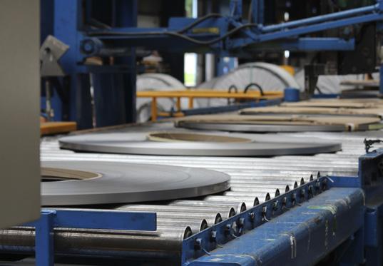
Figure 7. Strip coil is used to produce flexible pipe and longitudinally welded tube for umbilicals.


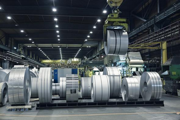
Figure 8. Corrosion resistant alloy strip is used to produce longitudinallywelded tube for umbilicals.
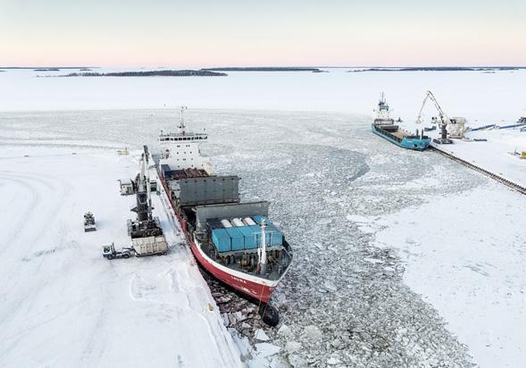
Figure 9. Outokumpu’s production has a relatively low carbon footprint as it is based on more than 85% recycled content. shallow seas, engineers can choose from the same range of alloys as clad pipe or MLP.
However, for flexible pipe in deepwater projects, it’s important to choose an alloy that provides high mechanical strength in addition to corrosion resistance. This will give both a seabed pipeline and risers the capability to withstand the hydrostatic pressure of deepwater.
Duplex or super duplex stainless steel provides the right performance for deepwater projects and for umbilicals. On a microstructural level, duplex grades are a combination of austenitic and ferritic stainless steel. As a result, they provide the combination of high corrosion resistance and high strength.
Lean duplex grades such as Forta LDX 2101 contain relatively low levels of alloying elements such as nickel and molybdenum and are suitable for less corrosive environments. However, duplex grades such as Forta DX 2205 and Forta DX 2304 are used widely in a range of applications and super duplex grades such as Forta SDX 2507 or Forta SDX 100 provide excellent corrosion resistance and high strength.
Sustainability Another big driving force today is sustainability. Targets to achieve net zero by 2050 are creating pressure on the supply chain to control the carbon footprint of projects and assets. This is set to grow during 2021, with the COP26 conference due to take place in November. Materials such as steel are produced by using large amounts of energy and so often contain high levels of embodied carbon dioxide. That is the term for the equivalent carbon dioxide emissions required to build or manufacture an asset. However, material from different suppliers can have widely varying carbon footprints. For example, Outokumpu’s alloys have a carbon footprint five times lower than some other suppliers. This is achieved by extensive recycling of scrap and by using low-carbon electricity to power the mills. Every tonne of austenitic stainless steel scrap saves 4.3 t of CO2 emissions.
A key thing for engineers to be aware of when comparing carbon footprint is that they should make sure they are comparing the ‘cradle to gate’ carbon footprint. That includes their suppliers’ direct emissions, for example from the burning of fossil fuels to heat furnaces. It should also cover CO2 released from the generation of electricity. Importantly, it must also include emissions from the material supply chain, which is sometimes overlooked but is typically the largest source of CO2 in a product.
So, while oil and gas engineers have many competing priorities for pipeline projects, there is no one ideal choice of material or technology. It is a question of optimising strength, corrosion resistance and cost to deliver the end customer’s preferred solution.
right level of corrosion resistance to minimise maintenance over a long life.
Moving up the scale, the high-molybdenum version 316L provides moderate corrosion resistance for offshore environments.
However, for offshore environments such as shallow seas with high salt content, the Ultra 6XN and Ultra 254 SMO alloys may be suitable. The latter has a cost advantage thanks to having high strength and a relatively low nickel content compared with other 6Mo types of stainless steel.
At the high end, alloys such as Ultra 904L and Ultra Alloy 825 can be used in sour gas applications. Alloys for deepwater projects and umbilicals Choice of grade for flexible pipes depends on the depth of the sea and the corrosiveness of the application. In


Arto Voutilainen, Ossi Lehtikangas, Antti Nissinen, and Mika Tienhaara, Rocsole Ltd, Finland, explain how the company’s deposition inline inspection tool can contribute to effective pipeline monitoring.


The key objective in flow assurance in the oil and gas industry is to enable and maintain continuous, safe and cost-effective flow of fluids in different stages of hydrocarbon production and transportation. One of the main issues in this field is the control and management of deposits, such as waxes, scales, asphaltenes and hydrates, since they can lead to severe production inefficiencies and even catastrophic blockages, causing significant losses. Deposition management The presence of deposition buildups in pipelines has many unwanted effects. Most importantly, they constrict the flow and therefore reduce the throughput, causing pressure abnormalities and increased risk of equipment failures. In the worst case, excessive amounts of deposits can even cause blockages that mean production needs to be suspended for a long time and extensive remediation effort may be needed. Deposits may also

weaken the effect of corrosion inhibitors so that lifetime of pipelines becomes shorter, due to under deposit corrosion and the increased risk of integrity issues.
Deposits in pipelines are controlled in many ways, the most important of which are regular mechanical cleaning, chemical dissolution, and various chemical inhibitors to decrease the deposit formation rate and controlling process temperature at a level that does not favour deposit formation or even dissolves existing deposits.1 In general, these preventative and cleaning actions can be very costly, and the natural ambition is to do them cost-effectively so that unnecessarily frequent cleanings or overdosing of chemicals can be avoided. Therefore, comprehensive information of deposit buildups in pipelines plays an important role in deposition management to minimise disturbances in production and to ensure effective use of resources. Most importantly, it helps operators to understand factors affecting deposit formation in their processes and, as a result, optimise preventative and cleaning procedures.
Several techniques have been proposed for investigating deposit conditions in pipelines. These include analysis of deposits scraped by cleaning pigs, monitoring of flow speed and pressure levels, and monitoring heat transfer from process fluid to surroundings. Caliper pigs can be used for mechanical quantification of deposits, and in some cases, ultrasound techniques may give indications on deposits even though accurate quantification may be challenging. Intentionally generated pressure pulses can be launched along the pipeline and by monitoring the returning pulse it is possible to obtain information on deposits and blockages. In addition, gamma-ray transmission measurement provides information on the presence of deposits, but their accuracy may also be affected by other factors. Tomographic gamma ray methods are very effective for accurate quantification of deposits but their applicability is often limited. Other tomographic methods include electrical tomography (ET) which can provide cross-sectional images of the interior of a pipeline in the sensor installation location. In addition, numerical models can be implemented for predicting deposit conditions in pipelines, but their accuracy can be limited due to the complexity of deposit formation processes and some experimental validation data is needed in the model development phase.2, 3, 4 Electrical tomography and inline inspection Rocsole Ltd has been advancing ET-based measurement technologies for deposit monitoring and is well aware of the limitations of fixed ET sensors. For instance, there can be different process conditions (both physical and chemical) in different parts of the pipeline and therefore deposit conditions can vary accordingly. It is clear that a small number of ET or any other deposit measurement sensors cannot give a comprehensive picture of deposits, especially if large portions of the pipeline are inaccessible, which is often the case, for example, with subsea pipelines.
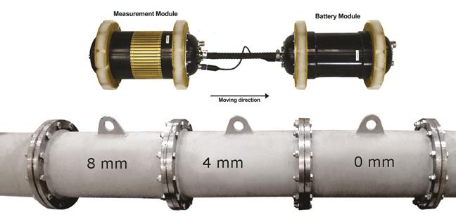
In order to have a comprehensive picture of deposits in pipelines, Rocsole has developed a deposition inline inspection (DILI) tool relying on ET technology. The fundamental idea of the DILI tool is that it travels through a pipeline collecting information on deposits in the inner wall. The tool consists of one or more cylindrical modules, and arrays of measurement electrodes are mounted onto the cylindrical surface of the measurement module. Electrodes are used to feed electrical signals to surroundings and electric potential of one or more electrodes is raised while other electrodes and the sensor vessel are kept grounded. This configuration generates a potential field and therefore electric current distribution to the surrounding area of interest, and induced electric currents are measured with grounded electrodes. Potential field and current density distributions in the surrounding area depend on underlying material properties and their distributions, as well as on the orientation of the DILI tool with respect to the central axis of the pipeline. Hence, electric currents measured from the grounded electrodes do provide information on the presence of deposits and their characteristics.
DILI tool specifications The DILI sensor vessel is built to carry all necessary components needed for measurements. In addition to the measurement electrodes, other main items are the battery pack, power controlling electronics, measurement electronics and data logger. The DILI system is also equipped with pressure and temperature sensors on both ends of the tool, and typically with an odometer. Depending on the operation environment and tracking needs, the tool can also be equipped with either an EM transmitter, an external radioactive source or both. All equipment does not need to be included into a single sensor vessel but, if necessary, they can be divided into multiple modules that are mechanically and electrically connected. Such multi-module systems may be needed especially in pipelines with small ID and tight bends, which can dramatically limit the size of an individual module. For unexpected issues in operation, the tool is designed to be bi-directional so that it can be run in both directions if needed. A DILI sensor is built such that its overall density (i.e. mass per volume) matches the liquid in the operating environment. Neutral buoyancy makes it possible for the DILI tool to be easily driven by the flow and no tight sealing is needed to guarantee sufficient driving force. This is essential since interaction with pipeline walls and deposits therein should be minimal, so that deposits are not affected or even collected by the DILI sensor.
Figure 1. Dual-module DILI tool for 12 in. pipelines (top) and three test sections of the flow loop (bottom).


