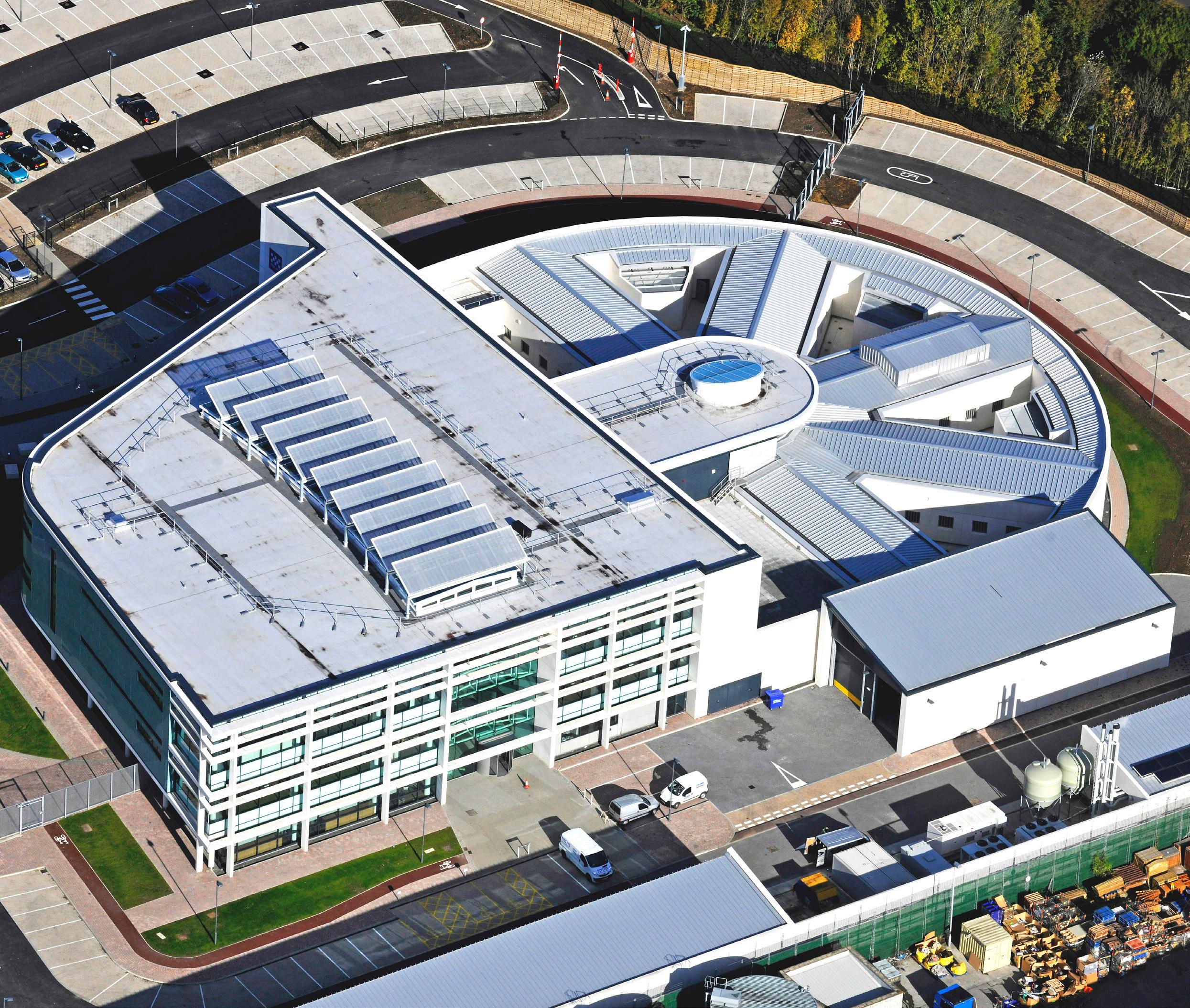


Specifically designed to surpass Home Office requirements, the PCE Offsite approach to the development of Secure Custody Suites ensures the highest levels of quality and robustness combined with an efficient fast and safe delivery.
PCE’s unique, flexible Design and Build delivery model, and approach to developing innovative alternatives to traditional forms of construction, has resulted in a structural solution which removes all the unpredictability and uncertainty of delivering complex custody facilities.

Designed to comply with the latest edition of the Home Office Police Buildings Custody Design Guide, and the resultant ‘Lambeth Cell’, the Secure Custody System has been developed and refined over many years to maximize the many
benefits of offsite manufacturing and onsite assembly efficiency and can be easily incorporated into radial, linear and bespoke custody layouts. The all-important police cells of the PCE Secure Custody System are based on DfMA principals using a common ‘kit of parts’ of components for all projects, these are configurable to meet the specific needs of any client’s particular scheme.
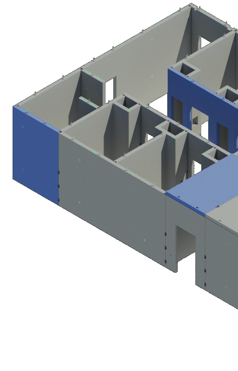
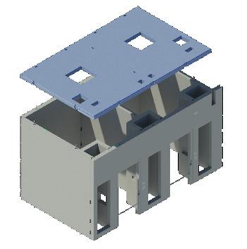
This ‘kit of parts’ consists of just four common components, three types of wall units and one roof unit, manufactured in reinforced precast concrete and configured to create an exceptionally durable ‘concrete box’ with the walls between and to the front and rear of the cells, along with the roof of the cell coming together to form a monolithic concrete structure. Repetitive use of the key components enables
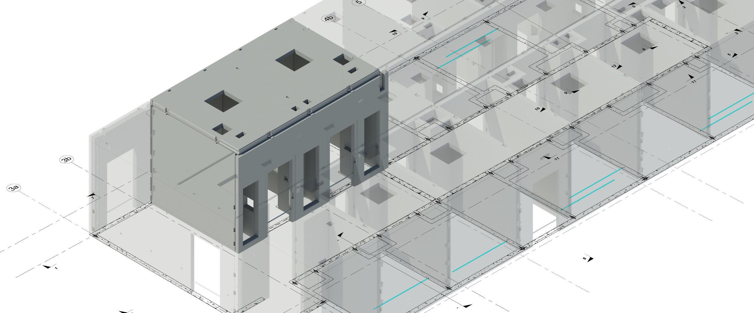
construction of Secure Custody
Suite blocks with a central access corridor between the lines of cells which can be configured to suit the needs of the project.
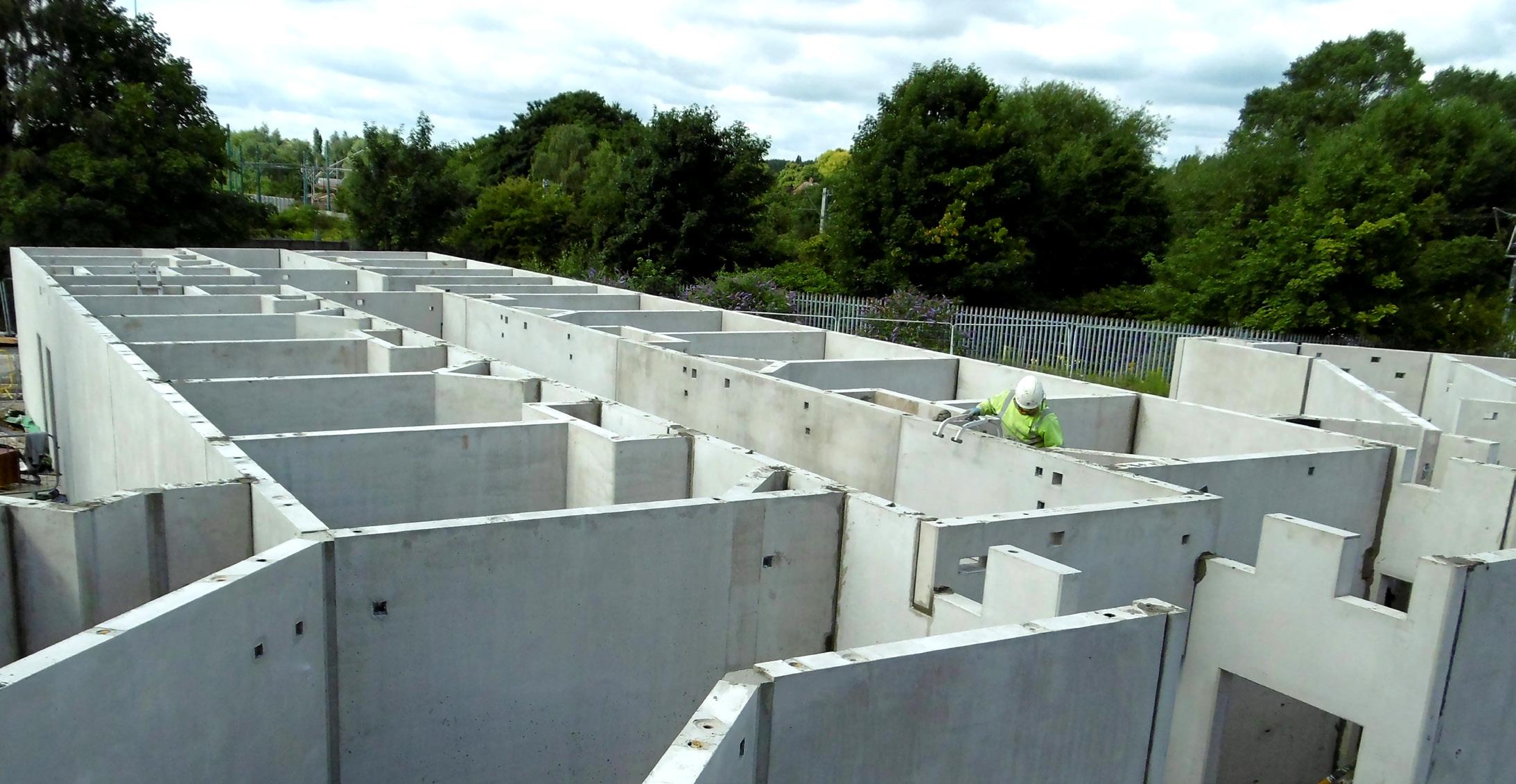
By maximizing the many benefits achieved by use of the standard key component set and their predetermined geometric features and limits, design integration between structure, building services, architecture and security features is simplified and streamlined, thus removing significant time and cost from the design development phases. The system generates significant benefits through the onsite construction phase with two cells assembled each day by just one crew of PCE’s specialist highly trained and directly employed construction team.
This Secure Custody System document is designed to provide all the information necessary for clients and designers to implement the principles of the system from design concept to ensure best value whilst removing redesign risk.
PCE’s Secure Custody System gives the projects design team the certainty meeting the optimal requirements in reinforced precast concrete construction of the Home Office requirements.

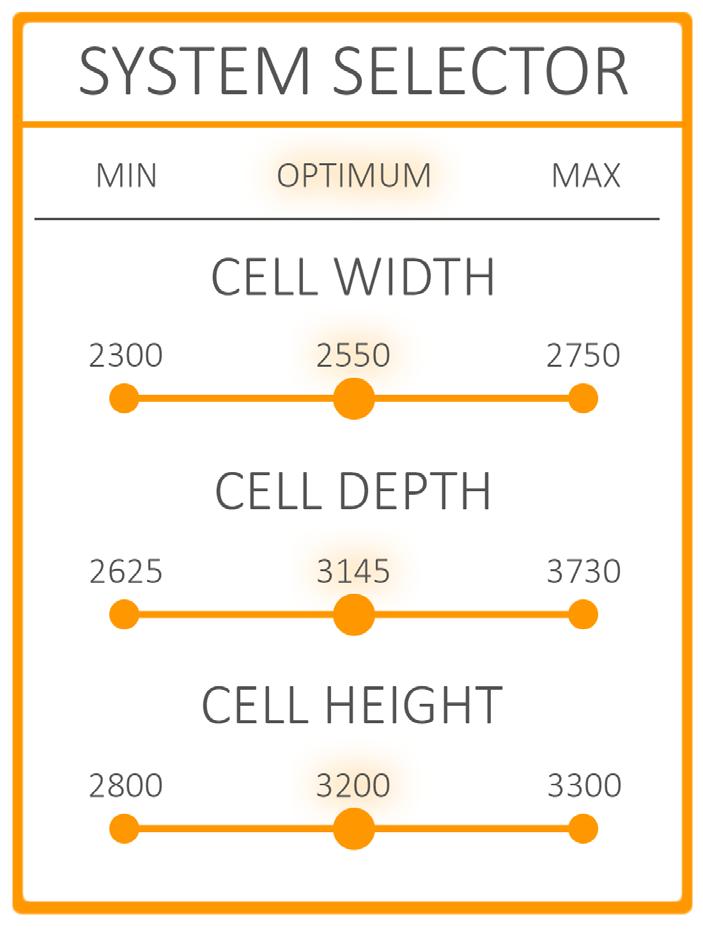
The visual above outlines the optimum sizes for the cell design whilst also confirming the flexibility built into the Secure Custody System that enables a project design team to configure other cell dimensions to meet their overall building design –should the optimum not suit.
The Secure Custody System has been designed and is constructed:
• for a 50-year design life
• in accordance with BS EN 1992-1:2004 Design of Concrete Structures
• to the National Structural Concrete Specification for Building Construction
• all projects are managed and controlled in accordance with PCE’s ISO9001:2015 Quality System
The cell roof units (that form the ceiling of the cell) are designed for an imposed loading of 7.5kN/ m2 allowing for the necessary plant and equipment to be located above the cells, with an additional allowance of 1.0kN/

m2 super-imposed dead load for any finishes. Steelwork roof structures are coordinated to align with principal wall lines with a maximum vertical ultimate load of 300kN per fixing location which are spaced at 2.3m centres minimum.
The cellular nature of the construction creates a robust series of support walls in each direction which provides stability for wind loads up to 1.4kN/ m2, suitable for most locations throughout the UK, provided altitude and physical geography is not significant.
PCE have developed a business structural system philosophy built around the selection of interchangeable `kit of parts`, each component’s smart connectivity allows it to `plug into` the next to create the complete structure. The designer can easily interchange the ‘kit of parts’ components and vary sizes from the optimum to create their own unique solutions for complete structures.
The Secure Custody System utilizes just four components from the extensive PCE ‘kit of parts’ library, with each manufactured off site under highly quality controlled factory conditions using a C40/50 concrete mix and designed to achieve a 60 mins fire rating with an XC1 exposure class.
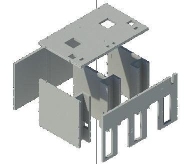

All components are 150mm thick and can be manufactured with varying surface finishes that meet the end user specification for custody suites, including for direct decoration, i.e., paint finish or for tiling.
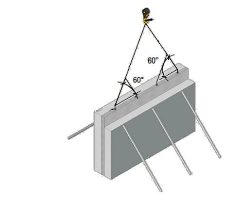
Every component incorporates all items, cast in during their production, required for connectivity, lifting/handling and temporary works requirements including on site propping and fall prevention processes.

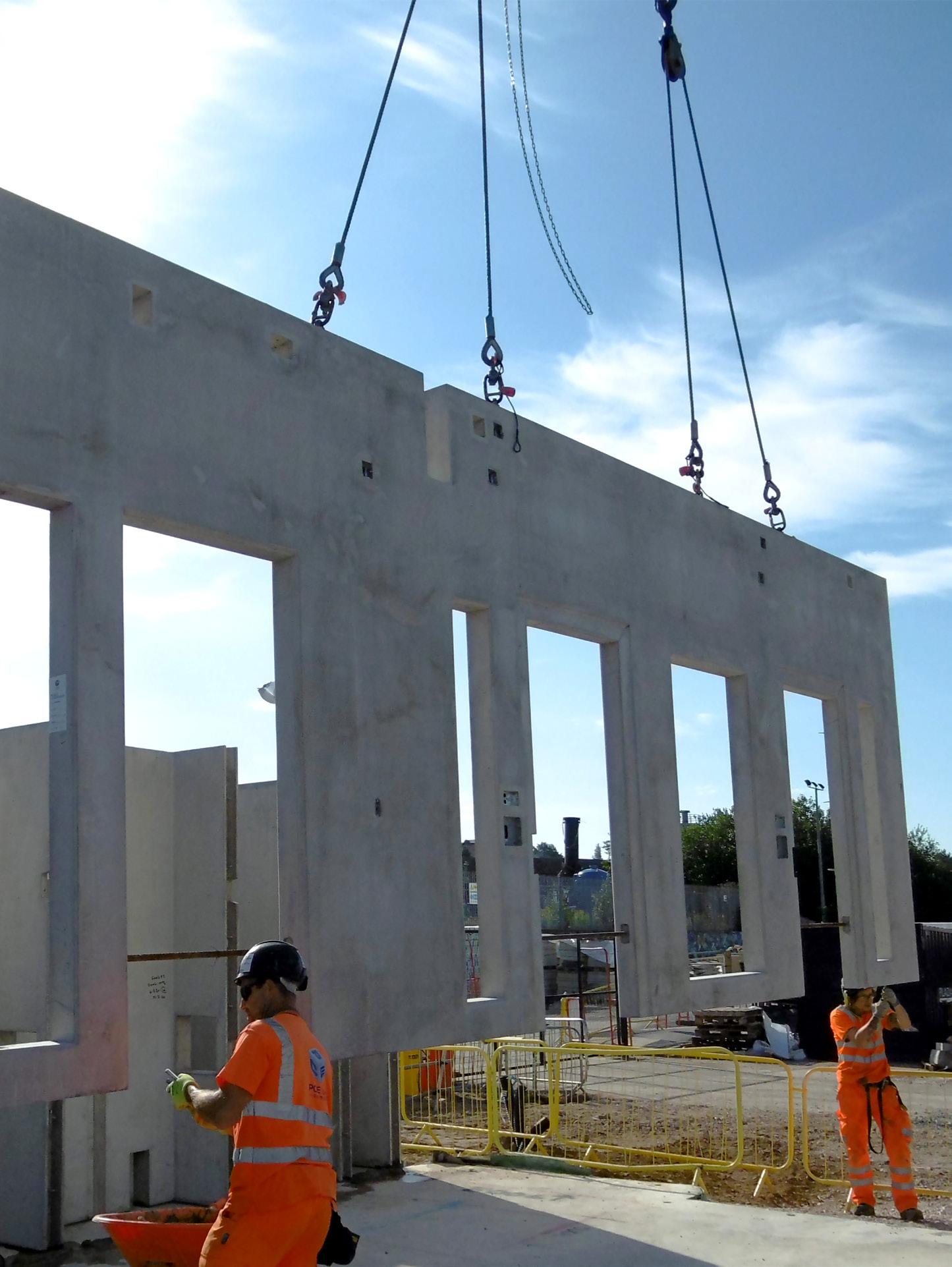
This component forms the outer secure line of the custody suite. Usually, these span two cells with a high-quality internal finish to receive direct decoration and skirting recesses cast in. The outer face is a basic finish which is cloaked by the chosen façade solution following construction on site. Window apertures, or fully cast in windows, can be incorporated if cell roof lights are not the preferred option with standard size of openings and locations available as part of the design selection process.

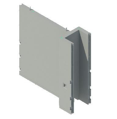
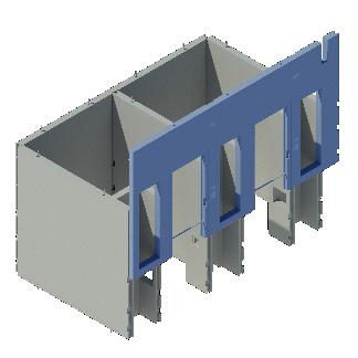
The Home Office design guide, and ‘Lambeth Cell’ design, allows for two differing widths of service ducts facing onto the corridor. The Secure Custody System includes specific solutions for each duct size which combine the dividing wall of the cell with the duct areas back and side walls to create a single bespoke `fork shaped` component. This minimizes joints in cells and accelerates on site build time whilst incorporating radial corner details for safe cell design. Duct walls are complete with standard sink and toilet apertures and provision for high level and low-level bench venting of the cell. Skirting recesses and cast in conduits can be added should the cell design require them.

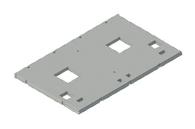
Each precast concrete roof component provides the ceiling to two cells, covering both the cell and duct riser areas. A standard aperture for the roof light is positioned centrally, but this can be removed if windows are provided to the external walls. Builders work openings are provided through this component to both cell and duct areas for extract vents and general service route provision. The underside of the component is cast with a high-quality plain finish to receive direct decoration whilst its top surface has an ordinary finish that forms the plant area floor above the cells.
The corridor walls generally span two cells, separating the individual cells from the open corridor area, include standard cell door apertures with safer radial corners incorporating cell door frame and lock recesses. Standard riser door apertures are provided either side of the main cell doors to the duct widths required. This intricate component includes cast in conduits for all cell call and affray alarm provisions that run from user level to their high-level exit points within the panel. Additional builders work openings can be provided to feed services into duct risers if necessary.
The Secure Custody System Duct wall moulds have been developed to give complete flexibility to the project designer when configuring the overall custody suite layout providing unique geometry to comply with Home Office cell design requirements and the unique geometry of the ‘Lambeth Cell’.
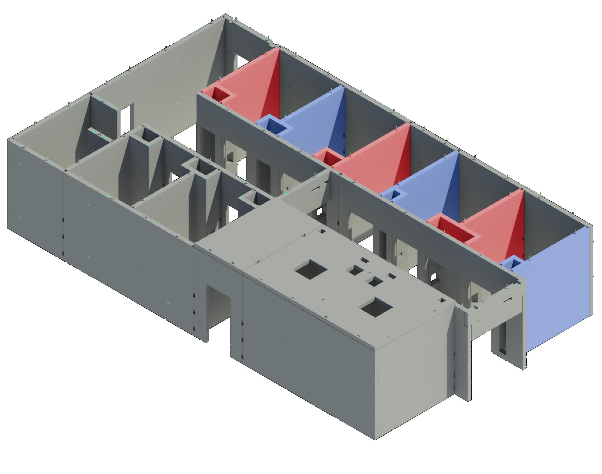
Essentially the System uses a large duct unit (shown red) and a small duct unit (shown blue). Each Duct size can also be provided with either a right hand, or lefthand riser, wall only. When such handed versions are required the Secure Custody System mouldage can be configured to include the continuation of the cell division wall to the duct, allowing the designer to make choices without creating more joints and additional component types.
Standard sized formers complete with all required tapers and chamfers to interface neatly with the glazed components are used to create the main roof light openings.

The optimum position for each roof light has been predetermined for each cells length and width to allow the roof unit to function structurally and most importantly for the roof light to be in its most beneficial position.
The same approach is applied to the builders work provisions within each cell roof component, these are set at pre-determined edge distances for the size of hole required.

The optimum setting out for each cell and duct door opening have been predetermined for each cell width and corridor wall size to allow the unit not only to function structurally, but most importantly to allow the interface with all cast in components to be clash free. Standard precise sized formers complete with all required radii,


chamfers, frame rebates and lock recesses that interface neatly with the secure metalwork components are used to form the openings.
A similar approach is applied to all other openings required in wall components. Windows have set variable positions that the
designer can select. Builders work provisions within each unit can be set at pre-determined edge distances (to wall panel edges) for the size of hole required. A simple set of rules that allows the designer to scope the builders work provision in the knowledge it will work structurally.


Duct walls connect into corridor walls with reinforcement ties through projecting wire loops in a fully grouted flush finished keyed joint.
Cell Roof components walls and each reinforcement dowels along key joint.
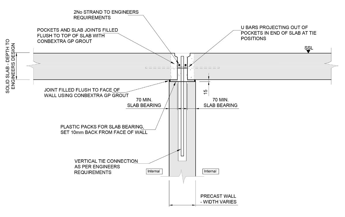

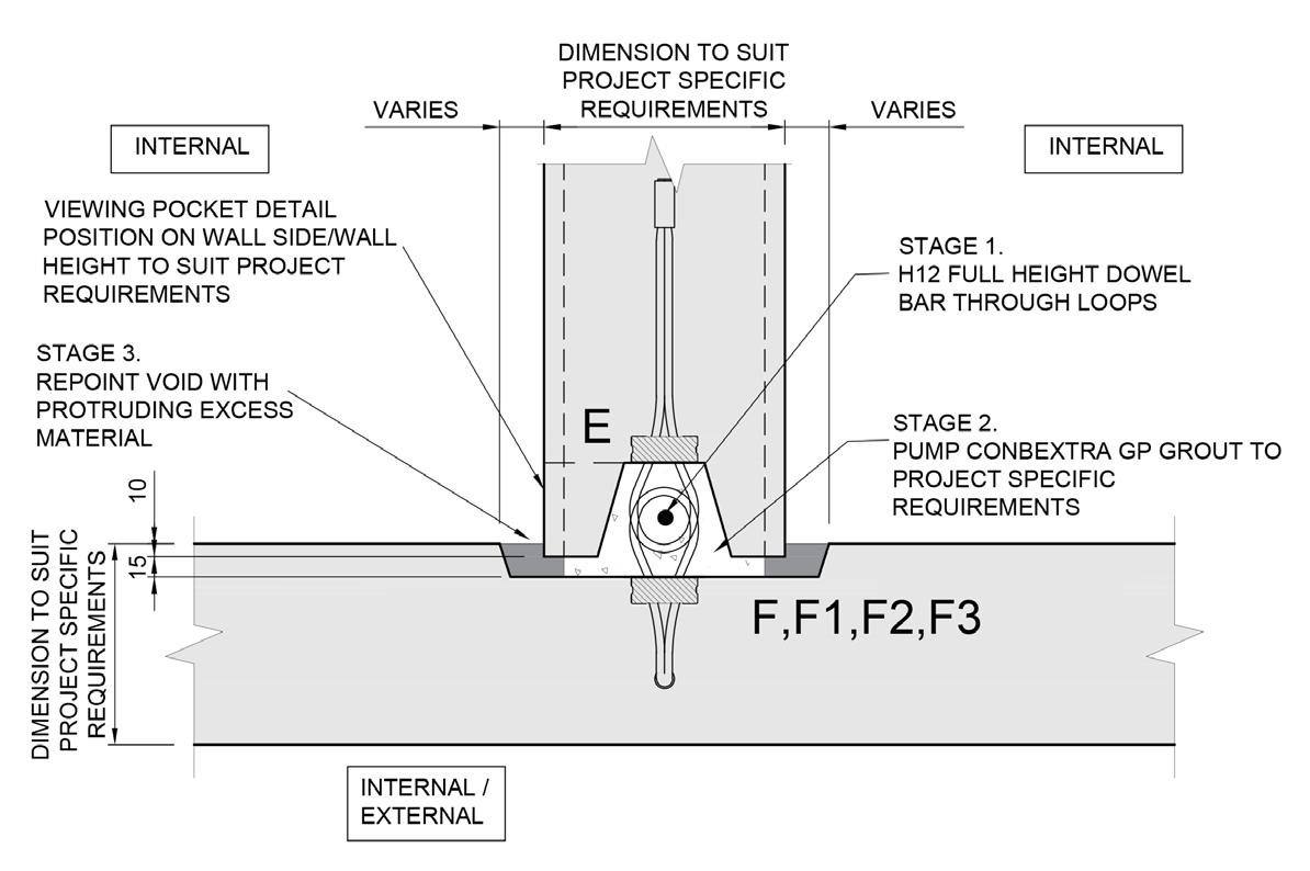


components connect to each other with projecting reinforcement loops over projecting along a fully grouted shear

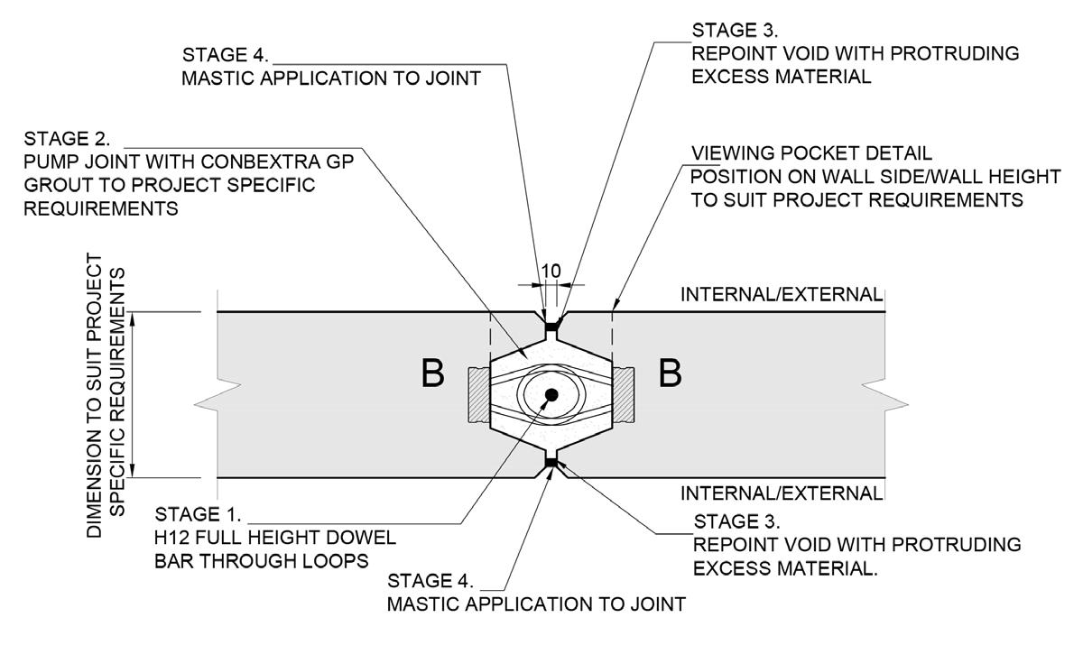
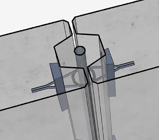


Duct walls connect into external walls with reinforcement ties through projecting wire loops in a fully grouted flush finished keyed joint.
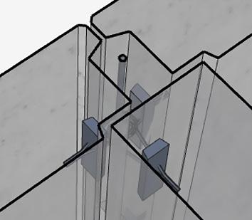
Corridor walls connect together with reinforcement ties through projecting wire loops in a grouted keyed joint which is expressed with chamfers and fixed with mastic, creating a visually pleasing joint line.

Each of the `kit of parts` components has its unique manufacturing methodology that creates the most efficiently designed unit to the correct quality. Types of finish, intricacy, design constraints and delivery/construction orientation are all considered within the manufacturing methodology, and it is in accordance with PCE Ltd ISO9001 Quality System.

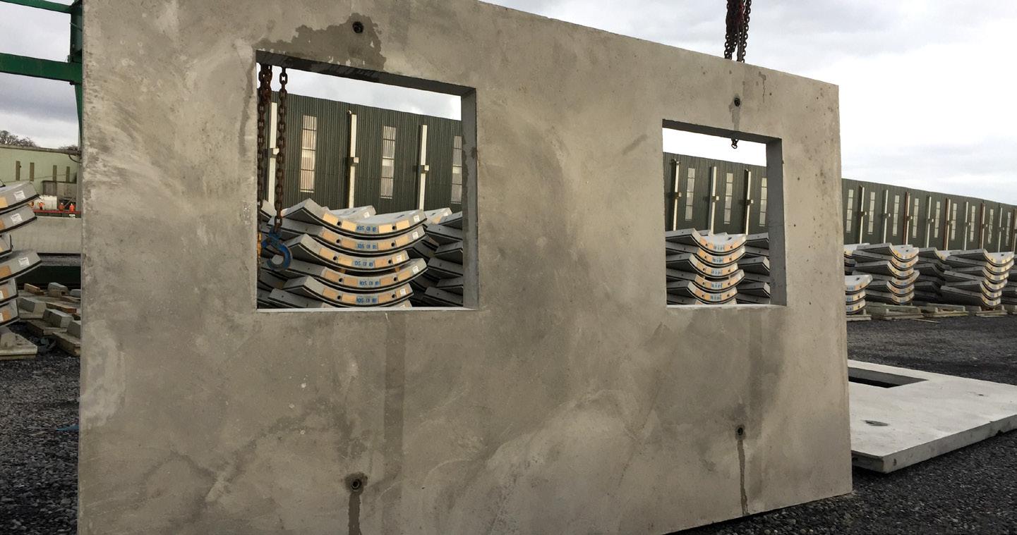
External walls are cast flat on variable steel tilt tables, ensuring a high-quality finish to the internal cell face and a floated finish is provided for the cavity face. Tilt tables are used to minimize unnecessary handling reinforcement otherwise required to turn the unit vertically into its delivery orientation.


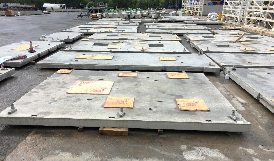
Cell roof components are cast flat on steel tables in their final orientation, ensuring a highquality finish to the cell ceiling and providing a floated finish to the upper face which forms the plant room floor. Magnetized steel formers are fixed onto the moulds to create the main roof light opening.
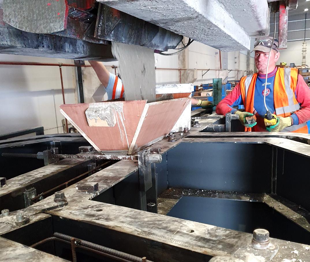
The intricate Corridor walls are cast from bespoke steel vertical moulds so that all the visible faces are formed against the mould faces to provide a highquality finish. Set into the moulds at standard positions are the bespoke profiled steel formers for the cell and riser doors. Specific key positions are set within the moulds for containment of the formers, ensuring they can be positioned accurately and held firmly during concrete placement.
The intricate Corridor walls are cast from bespoke steel vertical moulds so that all the visible faces are formed against the mould faces to provide a highquality finish. Set into the moulds at standard positions are the bespoke profiled steel formers for the cell and riser doors. Specific key positions are set within the moulds for containment of the formers, ensuring they can be positioned accurately and held


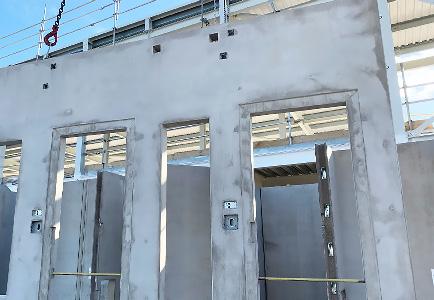

firmly during concrete placement. The fork shaped Duct walls are cast vertically using bespoke steel moulds so that all the visible faces are formed against the mould faces to provide a highquality finish. Set into the moulds at standard positions are steel formers for the sinks, toilets and vents. Radii and skirting recesses are also set into the moulds to ensure the accuracy of the key important details.


Delivery of components from place of manufacture to the construction site is preplanned starting at the design stage to ensure that loading, transportation and offloading is always carried out safely to meet the programme requirements whilst maximizing load carrying capabilities of the vehicles and thus minimizing their number to ensure the lowest possible

resultant logistics carbon footprint. Working in conjunction with their hauliers PCE Ltd have a vast experience and understanding of such Logistics Management and plan individual loads to ensure whenever possible that components are lifted from the vehicle directly to their final place in the Custody Block without the need for onsite storage.

Several separate “kit of parts” components are delivered by articulated vehicles consisting of cab and flatbed trailer up to 18.65m long and 2.9m wide with suitable appropriate stillage and restraints to ensure safe transportation up to a maximum single load of 26 tonnes.
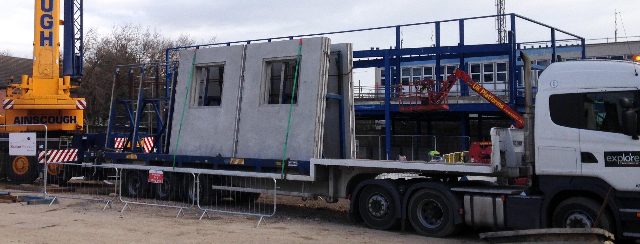
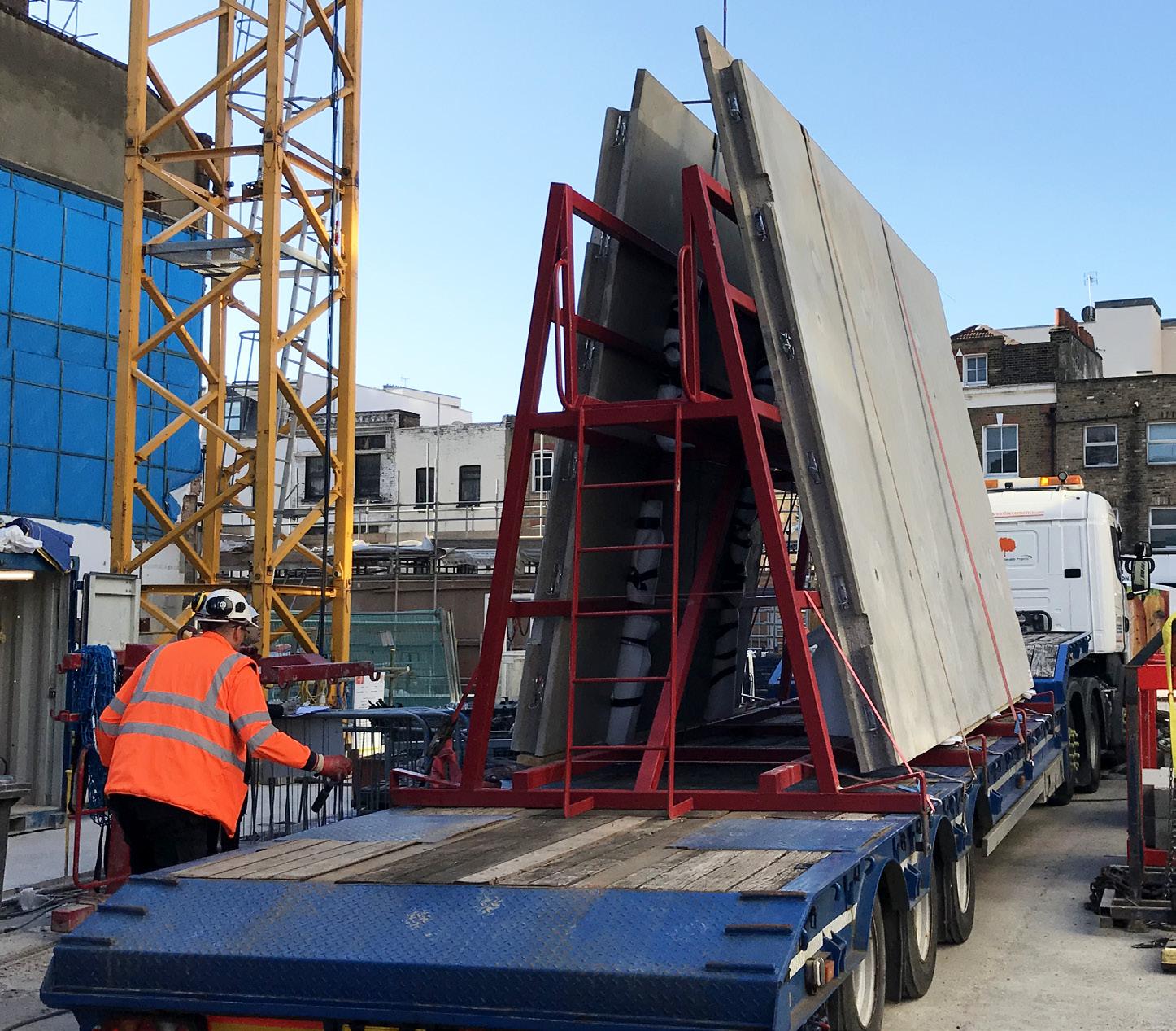
Should the transport route, site constraints, or for a particular project the need to deliver larger than standard sized components mean that vehicles as described above cannot be used then PCE Ltd will arrange alternative costeffective logistics to ensure that the projects overall programme is not compromised.
Ensuring safety and legal requirements for all their logistic operations is a key requirement of PCE Ltd and their hauliers, working in accordance to Department of Transport Road Vehicles (Construction and Use) Regulations 1986 amended October 2017, and the guidance and advice of the Road Haulage Association and/or Logistics UK as appropriate.

The Secure Custody System approach encompasses the design, offsite manufacture and onsite assembly phases. For the last phase, the benefits of maximizing the functionality of components and utilising proven connectivity translate into quick build times, quality and certainty of delivery.
Each of the 10 man on site assembly crew have a proven knowledge and experience that minimizes unpredictability and creates the `right first time` ethos of the construction teams.
The Secure Custody System approach goes beyond the components, all the digital management and quality records are specific and standardized. Key
documentation such as method statements and temporary works plans follow the system philosophy and are selected from the PCE system library.

The build strategy for the cell wings follows a simple 4 stage sequence:
1. Erect all external walls to create a full safe perimeter and set building overall dimensions.
2. Install duct walls to fix cell widths and critical duct and cell bench dimension, complete connections to external walls.
3. Install corridor walls to critical door setting out and create consistent wall lines, complete connections to ducts.
4. Erect cell roof units onto all walls and complete horizontal joints.
All provisions for temporary works propping are cast into vertical elements, all Cell Roof components are designed with no requirement for propping to minimize disruption to the structure and improve build times.
PCE’s DfMA approach optimizes all activities that be done off site by ensuring all cell roof components holes covers and handrail (or handrail fixings) are fixed prior to delivery. This not only improves construction efficiency but also creates a `safe by design` predictability to the operations and always ensures the highest standards of safety.
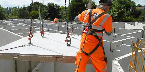


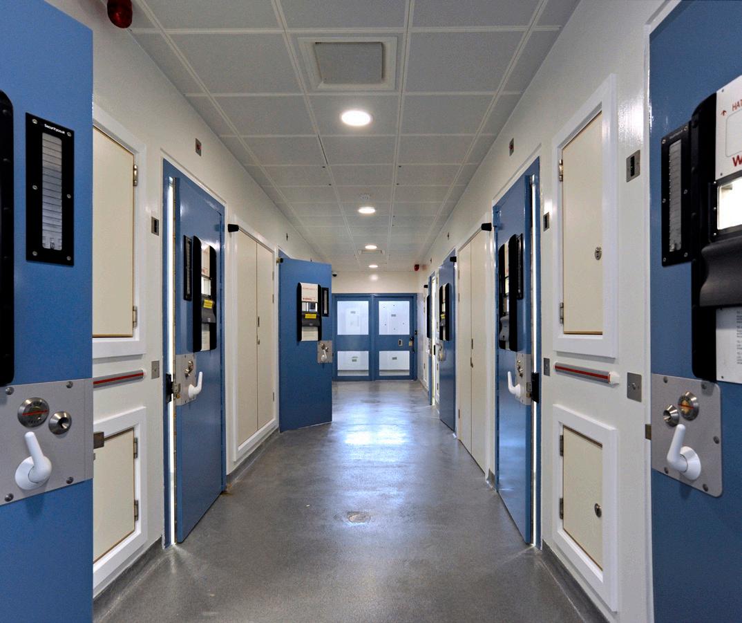
Structural components are manufactured from high strength reinforced concrete and structural tying on site is undertaken with pre-bagged high strength grouts and mortars forming a secure, monolithic concrete structural system. This materiality is perfect for creating a highly robust, durable environment which will easily resist the levels of ‘wear and tear’ you would expect within this kind of facility. The system is both simple and cost effective to maintain over the lifecycle of the building, it will not degrade over time, it will not require any replacement or expensive and obtrusive maintenance, and by its very nature, will easily outlast its design life.
Reinforced concrete is inherently fire resistant and provides excellent airborne acoustic attenuation. The component connections and interfaces are extremely robust, and the system is stable, thus no other stability mechanisms are required, and the structure will not suffer from any fatigue or movement.

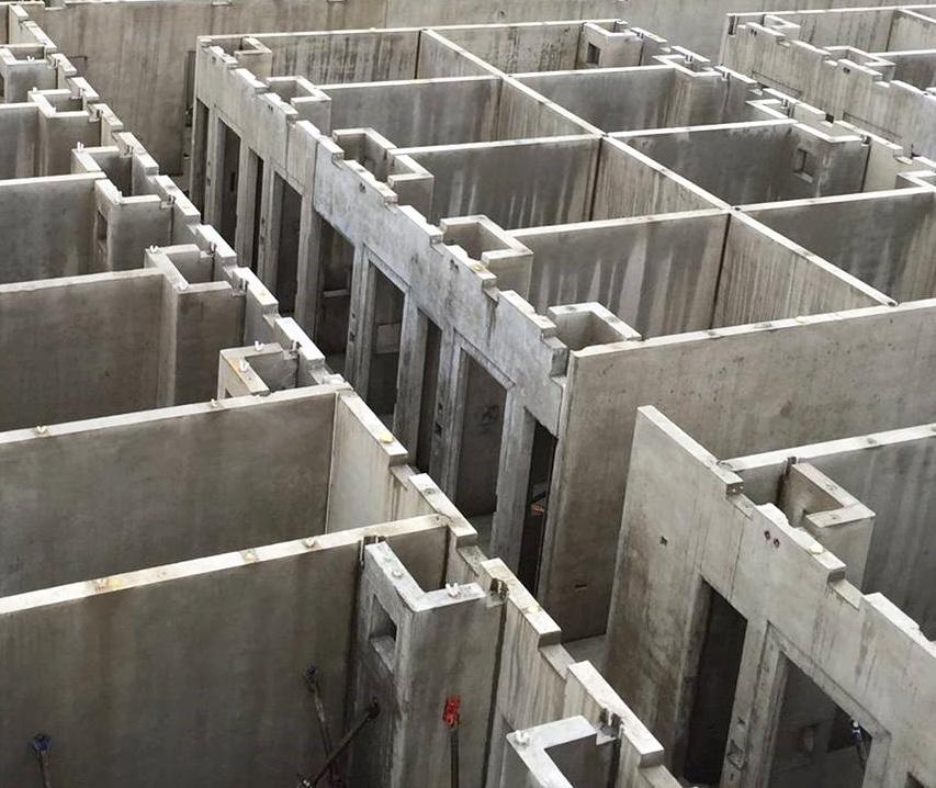

Components are manufactured offsite, under cover, in controlled environment factory-controlled conditions using high quality moulds and forms. Production processes are undertaken in accordance with fully auditable, accredited Quality Control Systems which monitor everything from material grading and consistency through to dimensional accuracy and surface finish. Concrete surfaces are formed such that internal finishes can be applied directly with minimal preparation removing the need for secondary finishes and linings.
The Secure Custody System has been designed and developed with the safety of all those involved with the manufacturing of components and their assembly on site in mind. Every step of the process has been meticulously mapped to identify risks so that wherever possible the risk can be designed out. Where risks remain, the hazard is controlled through the integration of PCE’s innovative safety systems and robust processes.

Both the services strategy and security functionality are integrated within the system to ensure an optimum, robust solution. Electrical containment for both security systems and lighting are embedded within the components during the manufacturing stage. Mechanical penetrations for all the servicing requirements are formed within the concrete elements to allow simple and efficient installation of the building systems. Security features such as cell doors, windows and roof lights are easily integrated within the system components via an approved set of common interface details.

The system is delivered in conjunction with PCE’s Digital Delivery Strategy providing Level 2 BIM compliance along with a digital management strategy which provides real time data at every stage of the process. The BIM model is used to collate and display intelligent data about each component part along with the status of that component at any stage of the project. This strategy ensures the integrity of the design data along with providing the project teams with the means to make informed decisions throughout the lifecycle of the project and collate lessons learned to help improve the system.


The system approach enables the design solution to be efficiently configured and coordinated with the other design disciplines. Standard designs and principles are drawn from the system library allowing manufacturing and construction information to be quickly produced using PCE’s in house automated design tools. By using supply chain partnerships and standard moulds, the manufacture of the system components can commence just 10 weeks after design has started and onsite assembly can commence just 6 weeks later. Each wing of custody cells is assembled in just 1 week so from start to finish, an entire custody suite can be completed in approximately 20 weeks.

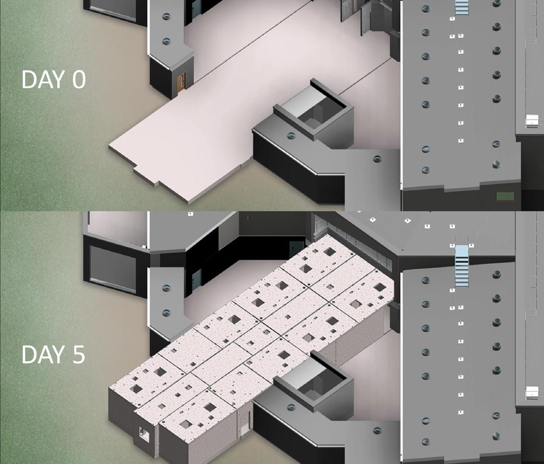

Through the utilization of a predefined standard component set, offsite manufacturing techniques and streamlined site assembly processes, waste is minimized or eliminated through every stage. Use of cement replacements and recycled steel in the precast components is commonplace to ensure embodied carbon is minimized. Construction impact is significantly reduced with dramatic reductions in site programmes, vehicle movements to and from site and the number of operatives required on site.
Project outcomes can be determined from the outset with much greater certainty. The system, its components and the processes adopted through delivery all contribute to high degrees of predictability whether it be programme, quality, safety or value for money.
The PCE Secure Custody System has been successfully used for over 10 years on numerous projects around the country with more than 900 cells constructed for both new build police stations and extensions to existing facilities.


The system is constructed from industry recognised materials, ie Concrete, Steel, bricks and Mineral Fibre insulation. All components are manufactured in accordance with relevant British and European Standards and accredited quality systems with full traceability and chain of custody for raw materials, components, assemblies, fixtures and fittings. Where applicable components and structural assemblies are supplied with a CE mark. Most components are manufactured within the UK with only a small number of specialist components being sourced via mainland Europe and North America.




Robustness and longevity of materials and components
We believe passionately in creating buildings that last, and the climate emergency demands that we do not use materials or assemblies that cannot meet their design life. It’s critical that we do not create a ‘weak link’ in our buildings.
• Compliant with Eurocodes and all relevant British standards
• Robust and compliant with all relevant Building Regulations


• Compliant with all relevant industry Best Practice


• Fire resistant
• Thermally efficient and Air Tight
• Excellent for both acoustic attenuation and resistance
• Excellent for Vibration
• Durable, with a design Life of 50 years
• Accepted by all major insurers and warranty providers
• BIM level 2 Accredited