13 minute read
Constructability & Prefabrication


Balcony Mock-up: Deck Finishes
One of the advantages of using timber is that it can be structural and used as a finish at the same time without needing a finish material over the timber. While it is safer to apply in indoor environments where there is better thermal control, it can equally be applied in the outdoor condition, acknowledging that proper and durable coating is periodically provided to enhance the serviceability.
Advertisement
Material honesty and exposing the underside of the balcony timber deck are important design considerations for Canada’s Earth Tower. As such, the balcony deck was designed and constructed with two timber materials, DLT and CLT, to test how it reacts to different weather membranes while meeting the structural loading requirements. Based on the supplier’s instructions, a clear finish coating was applied to the timber deck providing the necessary protection while keeping the wood grain that is essential to architectural honesty. The protective coating for the timber deck was applied on site once the timber had dried out after a few wetting and drying cycles. The wood had not weathered significantly prior to the coating application.
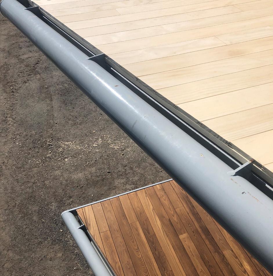
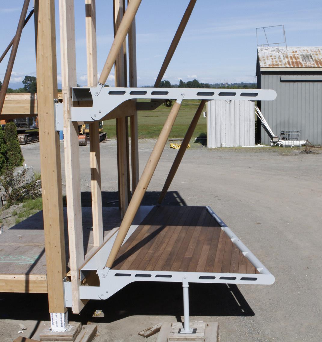
Figure 15: The ash decking material (lower) running parallel to the building enclosure face and the Accoya decking material (upper) running perpendicular to the building facade. As construction of the mock-up took place during a relatively wet season, it would have been prudent to have a factory applied base coating before shipping the prefabricated balcony deck panels to site to avoid exposing the timber deck to excessive moisture. Once the installation was complete, the final clear coating should have been applied to increase timber durability. Additional follow-up will provide a holistic analysis on how the timber deck performs under the exposed outdoor environment.
To examine performance and appearance of the finish decking, two different ways of running the finish decking boards were tested, the Accoya decking material was installed running perpendicular to the building envelope while the ash material was installed running parallel to the building facade (Figure 15). While the latter layout worked better as the support sleepers or strappings were continuous, running parallel to the water drainage slope, it created uneven interface conditions along the balcony front perimeter. The former layout resulted in a cleaner look along the perimeters, but a series of intermittent sleepers or strappings would be required to provide support while allowing undisrupted water drainage. How the deck finish is attached while maintaining the continuity of balcony roofing membrane, is a key consideration when planning for integration of decking finishes.
Balcony Mock-up: Durability & Weathering
As there is an increasing demand on employing exposed timber members for architectural aesthetics in an outdoor condition, it becomes a critical necessity to provide protection that enhances timber’s durability and weathering. Coupled with finish coating that provides weather protection for balcony timber members, careful selection and installation of balcony membrane is required to provide long-term moisture protection and proper balcony edge detailing to reduce the risk of water ingress into the wood components.
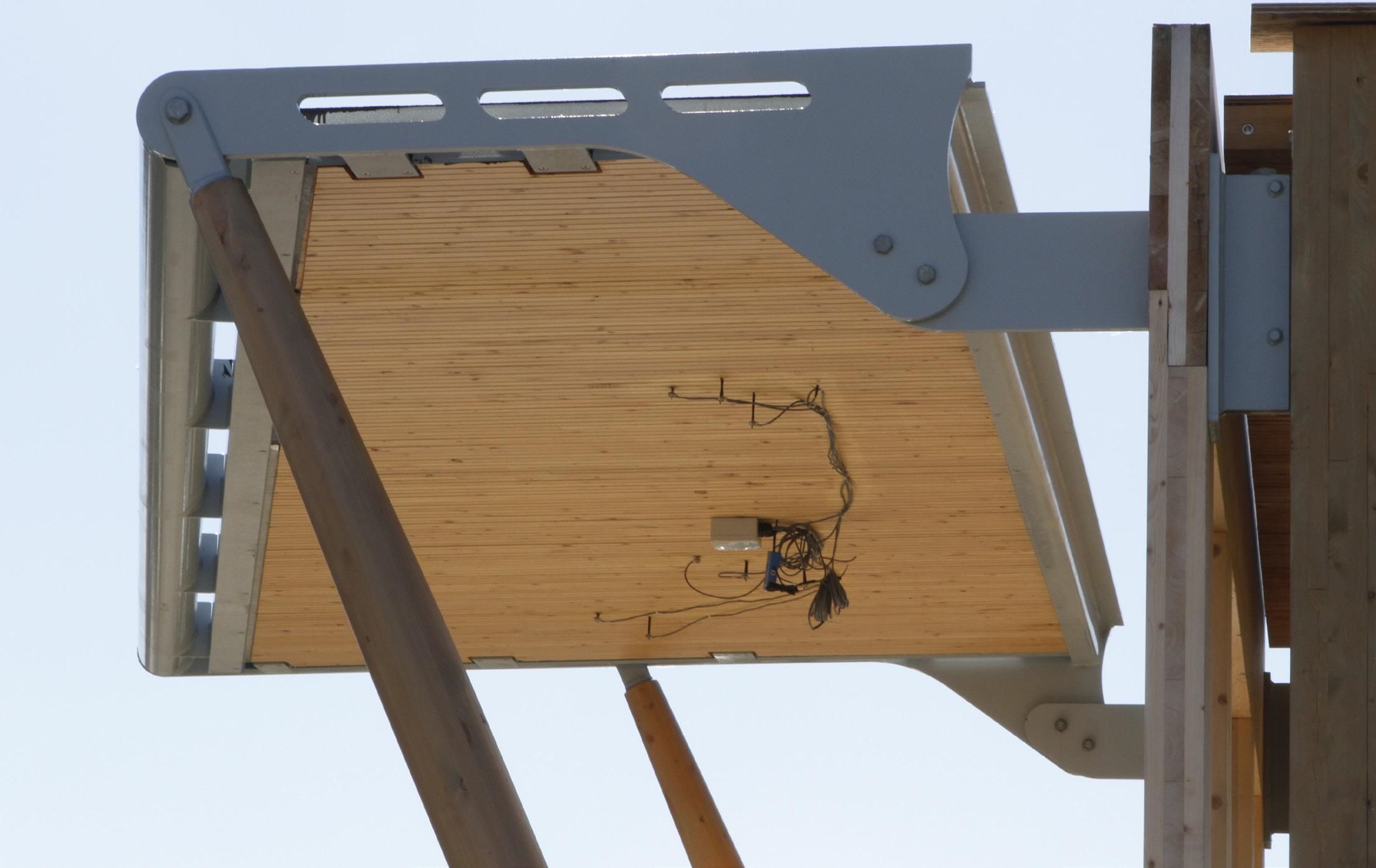
Two different types of membrane, two-ply styrenebutadiene-styrene (SBS) and a urethane membrane, were tested to investigate and understand the performance of how each membrane behaves to provide protection on DLT/CLT timber decks’ durability and weathering (Figure 24). Moisture monitoring sensors have been strategically placed on underside of the deck to monitor and log data of characteristics change of the timber decks. Further analysis in the post construction evaluation report will be shared.
Balcony Mock-up: Code & Bylaw Acceptance
While accommodating overall structural loads, all diagonal members must be designed to meet local code requirements regarding climbability and occupant safety. To mitigate issues with climbability, the balcony frame was designed to accept the struts outboard of the guard (Figures 14 and 17). This balcony mock-up has applied an interpretation to apply the mass timber diameter criteria to the struts from Table 3.1.7.1. This interpretation was made as there is structural fire-resistance rating required for these elements and there is no minimum diameter for Encapsulated Mass Timber Construction (EMTC) elements provided in Table 3.1.18.3 where only rectangular EMTC dimensions are provided.
Although it is not installed in this mock-up, sprinklers are required for all EMTC building balconies, even if they are noncombustible, when they are over 610mm in depth based on current BC Building Code and Vancouver Building Bylaw 2019. This is based on a concern with vertical fire spread in EMTC buildings at the exterior. Recent fire demonstrations involving exposed CLT compartments has provided data that supports the potential for a code change to relax balcony sprinkler criteria in EMTC buildings.
BALCONY OR PATIO AREA
PATIO DOOR LOWER ELEVATION OF HEADER AND DOOR TRACK ASSEMBLY
LIVING AREA
1980mm MINIMUM HEADROOM
MAX 200mm
BALCONY FLOOR LEVEL
300mm MAX MAX 200mm
STEP OVER UPPER ELEVATION OF STEP OVER AND DOOR TRACK ASSEMBLY
FLOOR LEVEL
Figure 16: Step over requirements from City of Vancouver’s Balcony and Patio Doors in Houses and Dwelling Units Bulletin
MIN 1,199 MM MAX 200 MM
ADDITIONAL BY-LAW CONFORMING LANDING
Figure 17: Minimum height to guard railing from City of Vancouver’s Balcony and Patio Doors in Houses and Dwelling Units Bulletin
Balcony Mock-up: Cost Effectiveness
Cost savings may be realized through the use of prefabricated balconies, but costs for the use of a hoist or crane to install the balconies must also be considered to have a meaningful comparison with other balcony construction solutions. Depending on specific project requirements, on high-rise projects the tower crane is normally kept to 6-8 weeks beyond the topping out of the primary structure; in this case the addition of the balconies as prefabricated items and requiring crane lifts may or may not significantly increase that duration. The total cost of incremental crane lifting to hoist all prefabricated balconies for Canada's Earth Tower would require additional analysis to determine exact amount.
While it is challenging to do a detailed ‘apples to apples‘ cost analysis at this prototype stage, our preliminary cost analysis indicated that the cost per square feet for this balcony mock-up is higher, comparing it to the conventional solutions constructed out of concrete or steel. However, this cost analysis does not holistically reveal full life cycle cost effectiveness of a prefabricated timber balcony construction solution. Environmental cost, such as carbon emissions of using timber versus concrete or steel and locally sourced materials versus outsourced ones, should be given equal consideration when assessing the overall cost effectiveness.
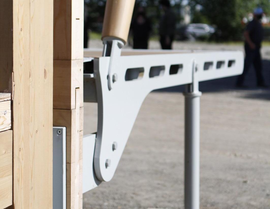
Figure 18: Custom steel connection through the unitized wall panel allows flexibility in adjusting the balcony height to address zero threshold condition.
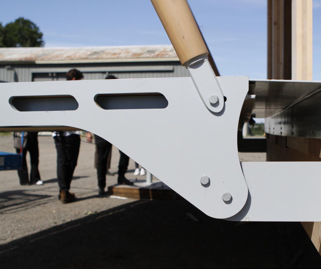
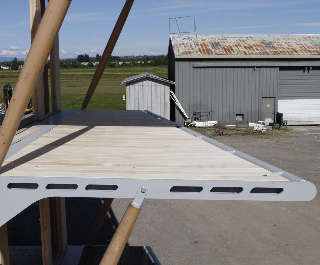
Figure 19: Balcony decking finish with ash decking material at the top and Accoya at the bottom of the balcony
Figure 20: On-site construction progress photo showing the custom steel connection between the balcony and glulam primary structure through the CLT wall panel.
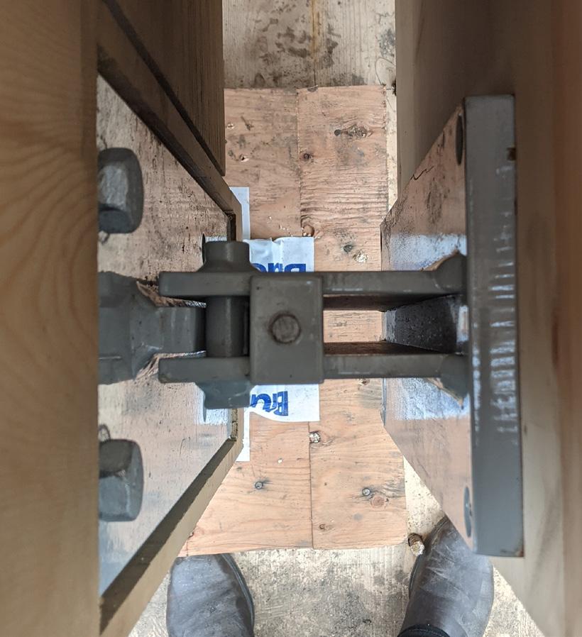
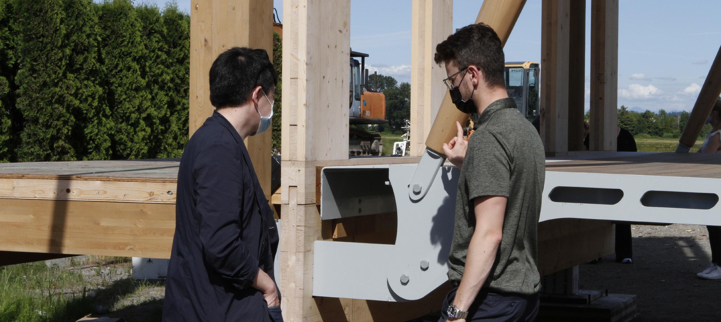
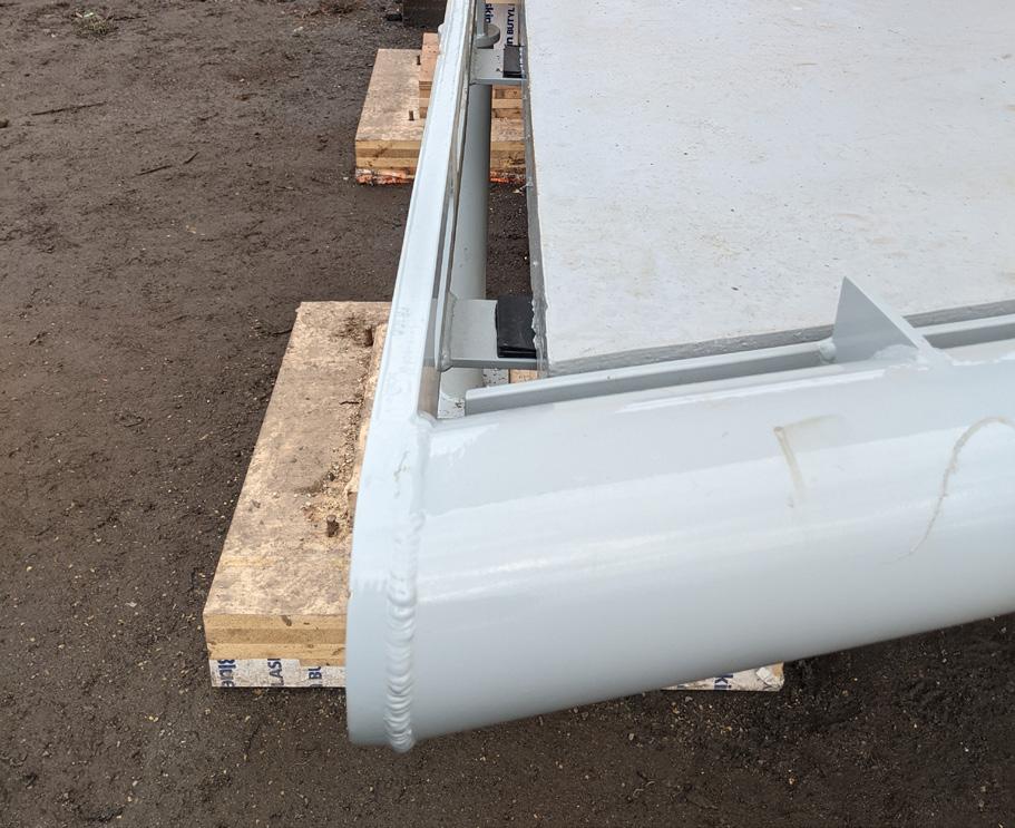
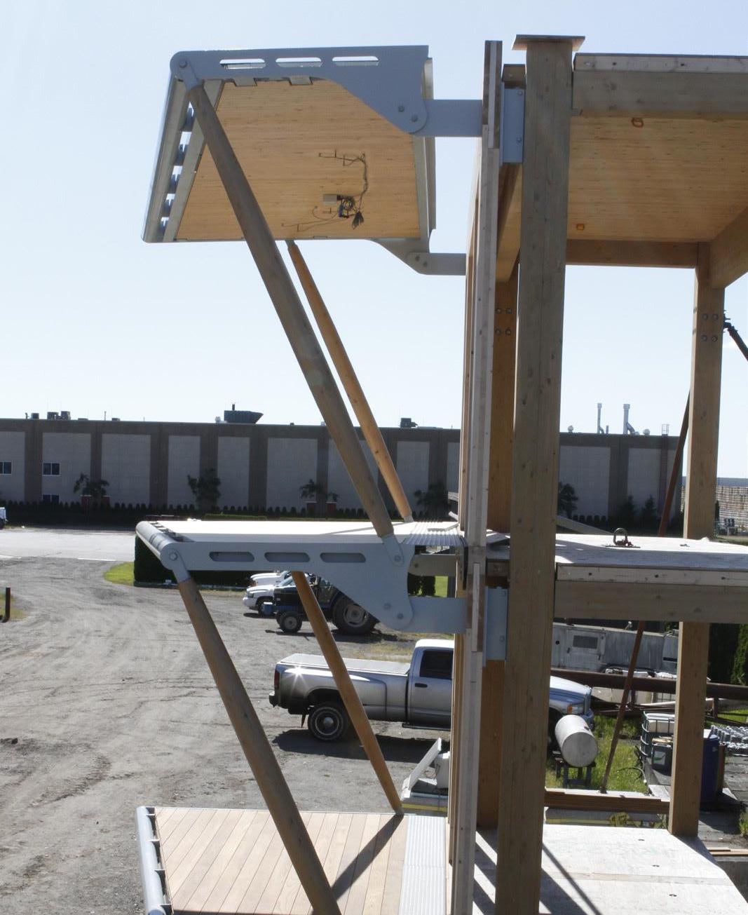
Figure 21: Balcony mock-up onsite progress with prefabricated balconies at two upper levels being put in place.
Figure 22: Balcony CLT/DLT support deck with SBS membrane applied, awaiting to be dried prior to placement of finish deck and support.
Lessons Learned
The balcony mock-up research investigated 11 key questions outlined in the introduction. While it is not an exhaustive investigation, the balcony mock-up process identified a number of key themes around which the lessons learned section is organized.
Structure and Durability
While the balcony connection approach utilized in the balcony mock-up is proven to have a potential for scalability for large applications, additional structural analysis and coordination is required to design and locate custom steel connection plates in the unitized envelope system and primary structure to support balcony structural elements. Bolted or welded structural connections must be carefully detailed to prevent risk of water ingress and may require periodic inspection.
One of the key study areas is durability of the balcony-towall interface and balcony components. While the balconyto-wall interface is critical for overall building enclosure durability, the mock-up focuses on the balcony assembly itself. Mass timber—DLT/CLT balcony support materials in the case of this mock-up—tends to slow not only the flow of water vapour across the floor assembly, but also the drying process. As such, keeping the timber elements, especially those in the outdoor environment, in a desired moisture level across the life span is important.
Thermal Performance
As critical as balcony structure durability is, it is important to understand the thermal performance of a balcony connection design and its related impact on meeting increasingly stringent federal, provincial, and municipal building performance requirements. To do so, the balcony design must consider the context of the overall building performance. Thermal bridging needs to be mitigated especially when there are a high number of balcony connection points that penetrate the building thermal enclosure and weaken the overall building performance. It’s critical to reduce the extent and number of connection points between the balcony and the building’s thermal enclosure by strategically designing the size and shape of the balcony with minimal thermal envelope penetration in mind. It is key to consider structural thermal isolation in the connection details to reduce thermal bridging (Figure 23).
1
2
6
3
4 5
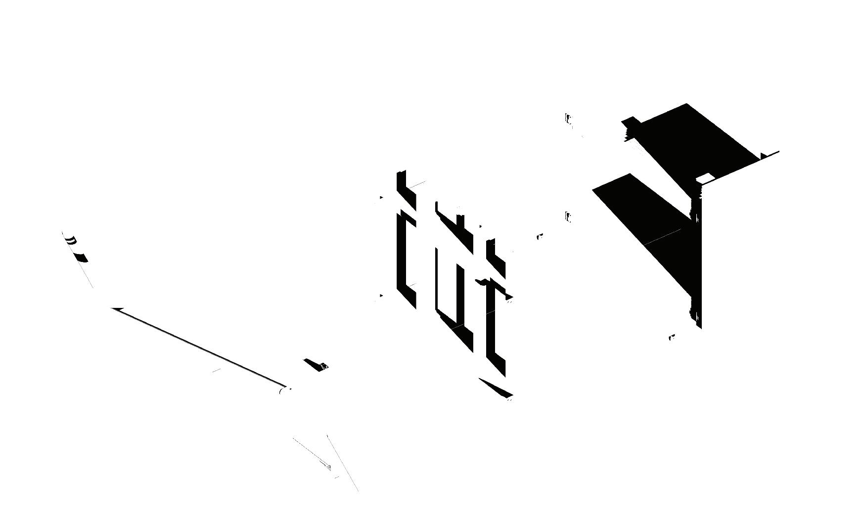
1. Primary Structure
2. Module Unitized Envelope System
3. Balcony Connection Bracket (Built-in Glulam Column Primary Structure) 4. Balcony Connection Bracket (Built-in Module Unitized Envelope System) 5. 165mm x 32mm Structure Steel Side Plate
6. 165mm dia. Balcony Glulam Pole Strut
Figure 23: Axonometric drawing showing a balcony customized steel connection with minimal connection points to reduce the thermal bridging.
When it comes to thermal performance of a balcony system, off-site fabrication of the balcony with a discrete custom connection detail (Figures 23 and 24) to the building structure tends to do a much better job than the conventional slab extension approach. The prefabricated balcony modules are manufactured with greater precision than on-site construction, but the coordination among various trades is complex and requires a clear chain of communication to ensure all design components are put in place prior to fabrication and site installation to avoid onsite discrepancies.
Constructability and Prefabrication
Utilizing the face-mounted balcony attachment approach, the balcony mock-up investigated the method of transferring loads from the thermally broken balcony to the primary structure through a unitized cladding system. Steel connections in the timber structure provide flexibility with accommodation of loading. Custom built-in steel plate connections in the primary structure coupled with a prefabricated unitized wall panel system ensures effective installation of the overall building envelope on site while minimizing site mistakes. While this approach may reduce the complexity and quantity of penetrations through the building envelope, it requires careful consideration of differential movement between the balcony and interior structure when applied to tall buildings with a potential risk of being exposed to stronger lateral forces. Given that mass timber gains momentum in the construction industry, prefabrication building techniques are proven to be an efficient way of making a new generation of high-performance buildings possible. Compared to the conventional site-built approach, prefabrication provides a controlled factory environment that allows for enhanced quality assurance and control, reducing the risk of deficiencies. In the case of this balcony mock-up, the complex connection steel plates were pre-built into the primary structure and unitized wall panel system, allowing for quick and efficient erection of balcony assemblies (Figure 25). It also provides flexibility with construction scheduling and construction waste reduction. Once the primary support structure and unitized wall panels are put into place, prefabricated balcony modular units are fastened to the steel bracket. While it is quick and efficient, careful consideration should be given to the maximum size and weight of the prefabricated panels, as well as the method of transportation and installation of the panels.
One of the advantages of the prefabrication approach is that it provides a way to decouple the balcony structure from the interior floor, allowing for a zero-threshold balcony condition to accommodate accessibility. However, it is important to coordinate decking material thickness and supports early in the design process in order to achieve this. Ideally, the same manufacturer provides both the decking material and the associated support if possible. Integration of balcony door threshold into a unitized wall panel system is important to avoid on-site additional work.
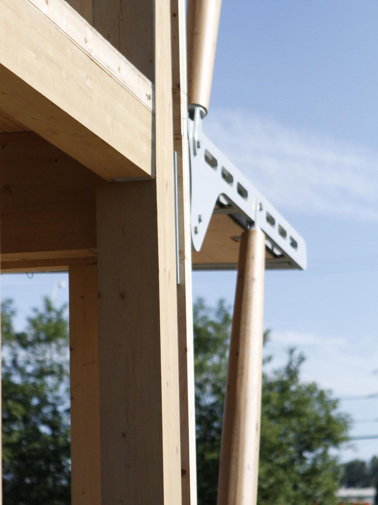
Figure 24: Installed balcony modular unit with the bolted connection interface between balcony unit and steel bracket that comes with the prefabricated unitized wall panel system.
5 4 1
2
3
6
7 11
10
8
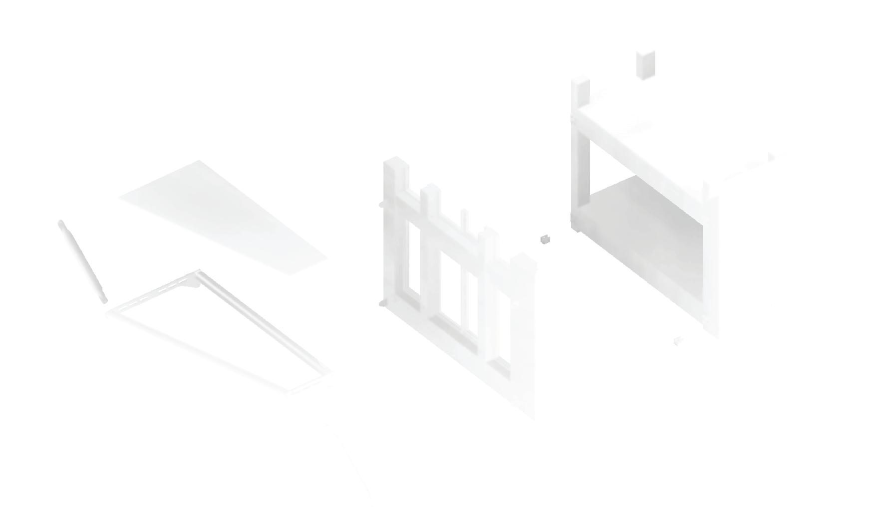
Figure 25: Axonometric diagram showing the balcony components and construction sequence of how they are assembled.
9
1. Finish Decking (Accoya/Thermory Running
Parallel & Perpendicular to Balcony/Facade
Direction on Different Levels) 2. Half Reinforced Urethane Membrane/
Modified Bituminous Membrane Roofing 3. 3-Ply CLT/2x4 DLT Balcony Deck
4. 165mm x 32mm Structure Steel Side Plate
5. 165mm dia. Balcony Glulam Pole Strut
6. 165mm dia. Steel HSS Pipe
7. Lower Balcony
8. Balcony Connection Bracket (Built-in Module
Unitized Envelope System) 9. Balcony Connection Bracket (Built-in Glulam
Column Primary Structure) 10. Unitized Envelope System
11. Primary Structure
Detailing should be well thought-out in terms of transition support from the interior floor to the balcony deck finish and flashing termination, ensuring proper sequencing and execution of continuous building enclosure control layers early on the design process.
While the guard attachment was excluded from the balcony mock-up due to budget limitations, it should be given enough attention early in the design process, so it does not interface with or penetrate into the wood components. Depending on how the guard attaches to the balcony while meeting lateral load requirements, it is important to consider proper balcony edge membrane overlap, to avoid penetrating the weather membrane, and to consider proper flashing termination.
Figure 26: Final balcony mock-up photo—the guardrails were not installed due to limited budgeting. However, the perimeter guardrail would have been fastened to the steel support structure so not to interface with or penetrate into the wood components, while keeping weather membrane undisrupted.

Clockwise from Top Left:
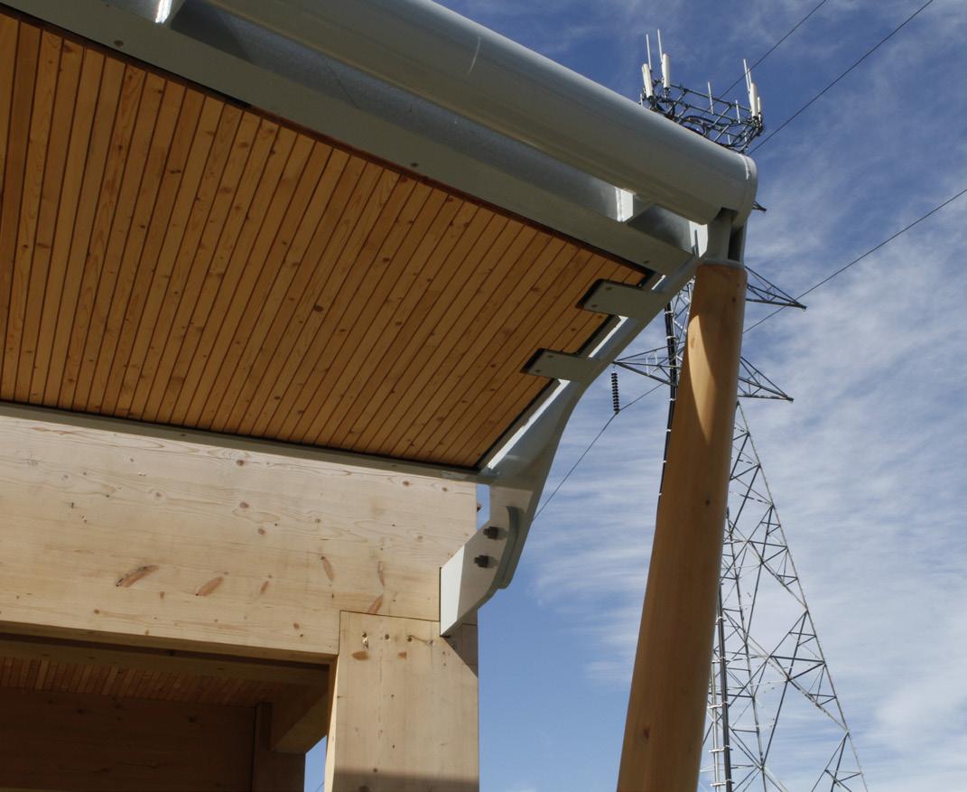
Figure 27: Steel side plate receiving the top and bottom level compressions timber steel hybrid struts.
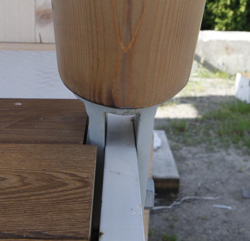
Figure 28: Finish decking adjacency to the connection between timber strut and balcony steel side plate.
Figure 29: Two-story balcony mock with finish decking put into place. Due to costing and scheduling, the insulation and cladding layers were not included in the mock-up, but the required space to accommodate insulation and cladding was shown.
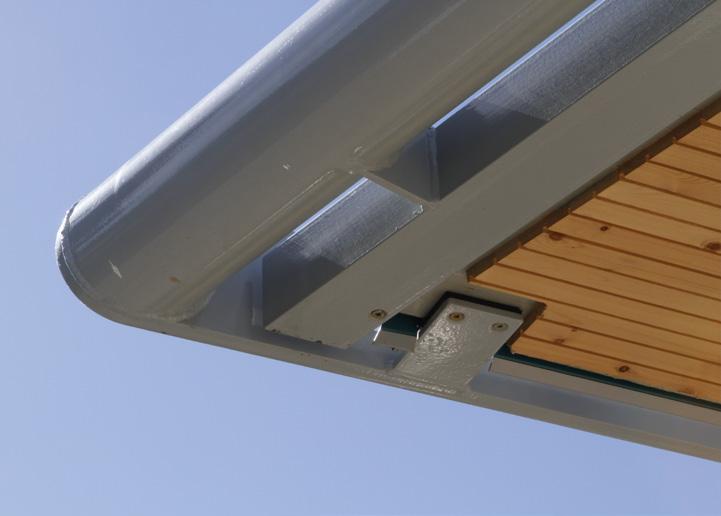
Figure 30: Showing the perimeter flashing detail where it interfaces with the outside steel structure. The detailing could have been improved to simplify the waterproofing membrane application.
Clockwise from Top:
Figure 31: Moisture monitoring sensors were installed underside of DLT/CLT decking to monitor and provide data on wood characteristics over a period of time. A separate report will be issued on performance analysis of the timber decking proprieties and recommendations.
Figure 32: The wood struts have large portions of end grain exposed and facing up. Periodic maintenance through re-coating is required to enhance the timber strut durability.
Figure 33: Showing the notches on the underside of the decking for the structural tabs, which requires additional attention in detailing to avoid a potential moisture accumulation and deterioration of timber decking.