
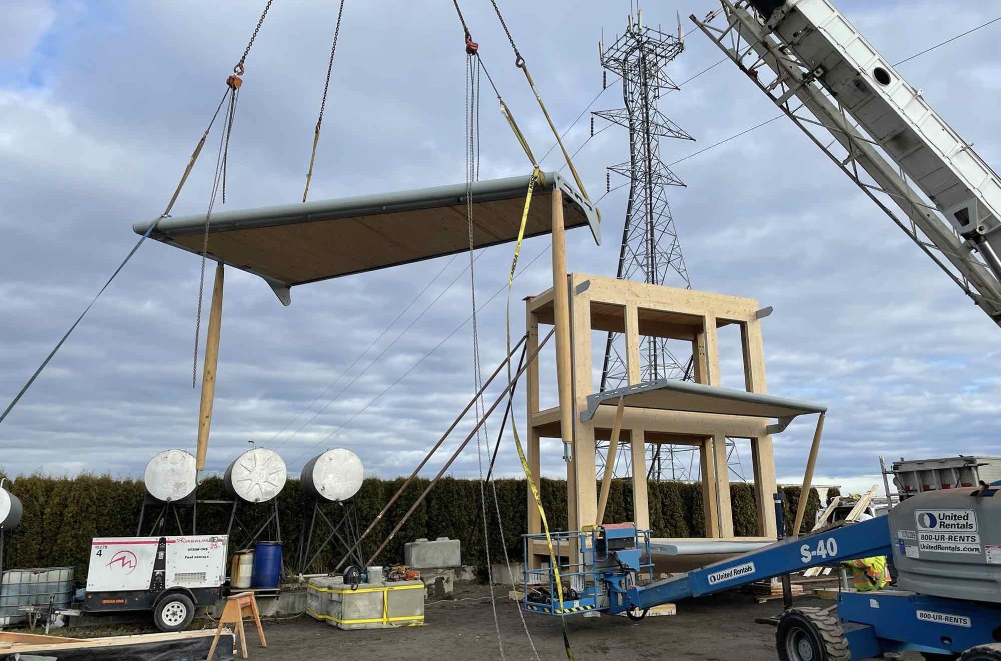
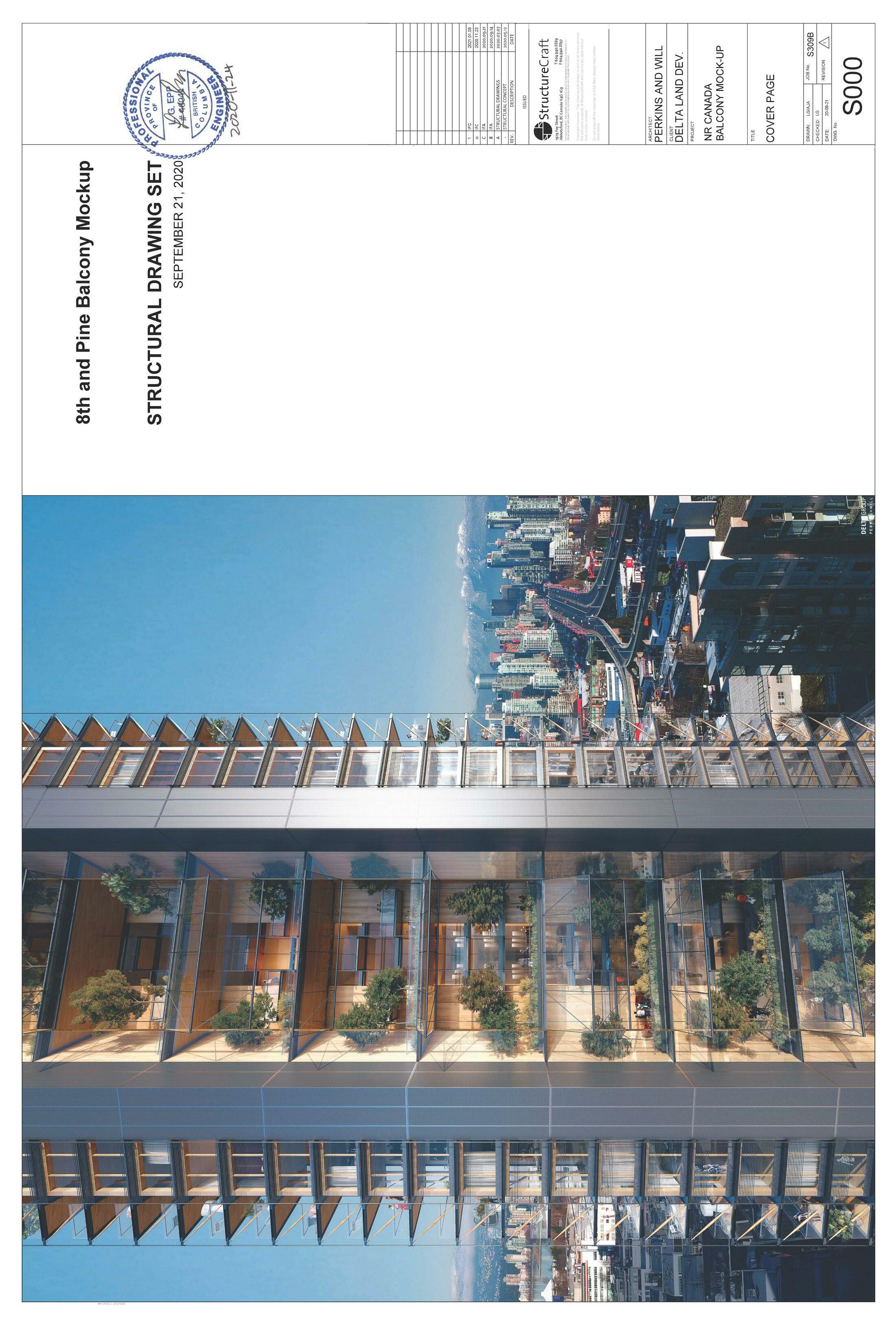
July 29, 2021 Canada’s Earth Tower: Balcony Mock-up

Balconies are an important consideration in many jurisdictions for multi-unit residential buildings both as a functional extension of the living space and a key component in the overall building thermal performance. Also, they are essential design components that pose significant challenges for the successful execution of competing structural, fire and thermal requirements. These challenges are amplified in mass timber construction due to added new design challenges regarding structural connections, building enclosure detailing, and proper waterproofing membrane application. Overcoming these barriers and providing solutions to address them will improve the acceptance of timber as a viable structural system. For thermally broken balconies with mass timber components, the strategies developed as part of this objective are applicable as lessons learned to other projects and the focus of this research report.
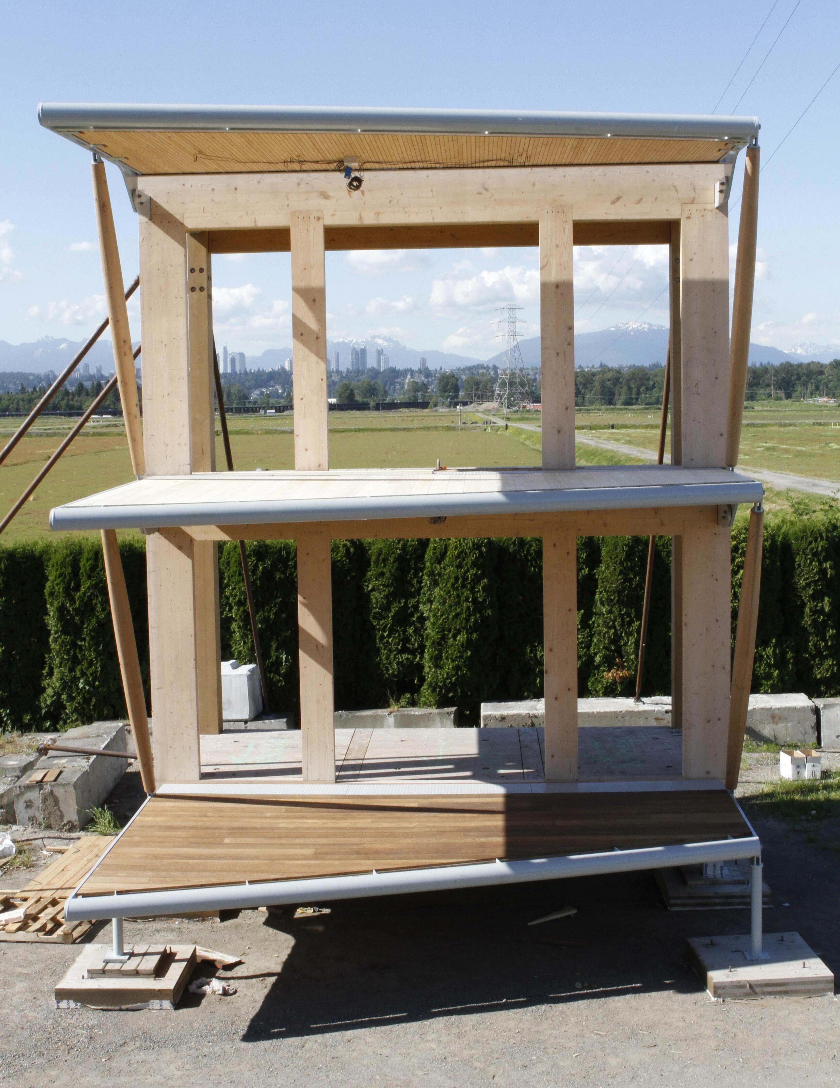
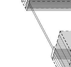
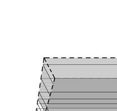
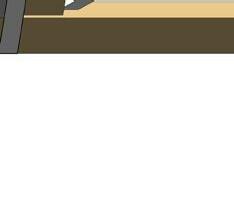
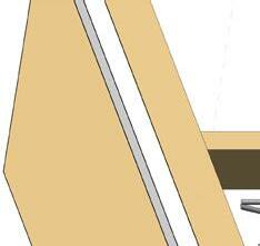
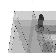
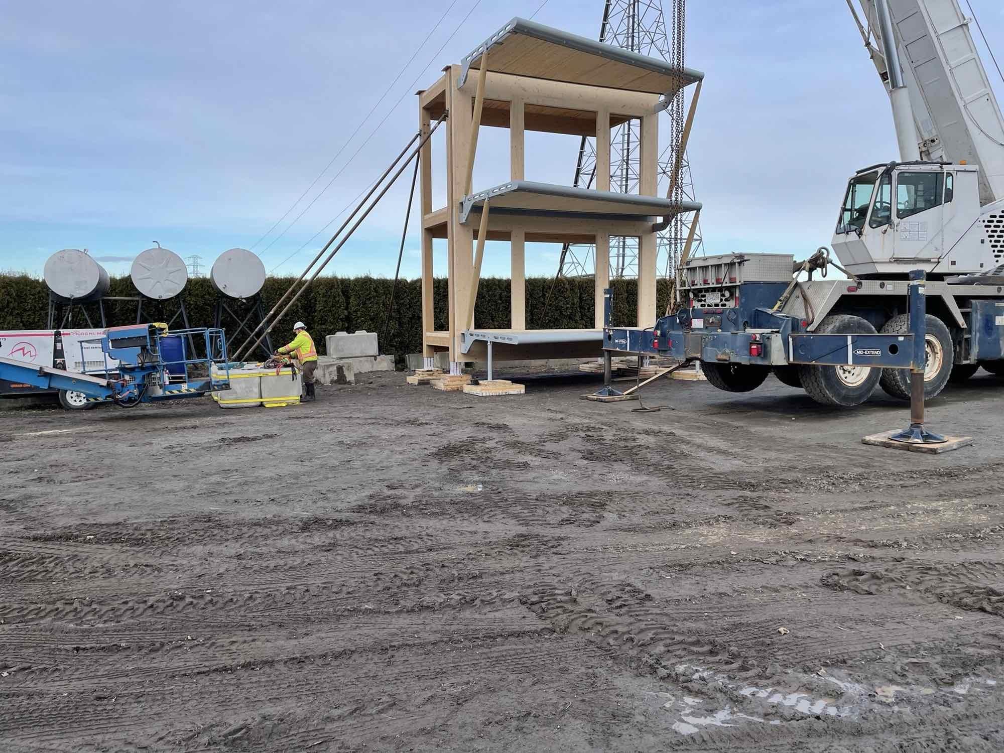
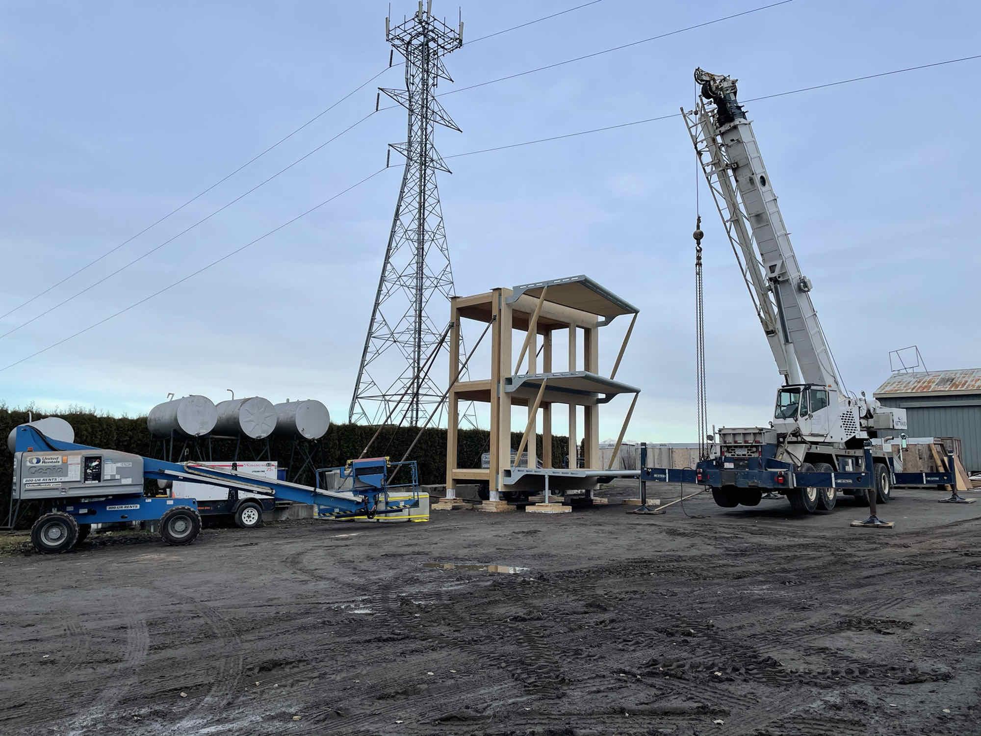
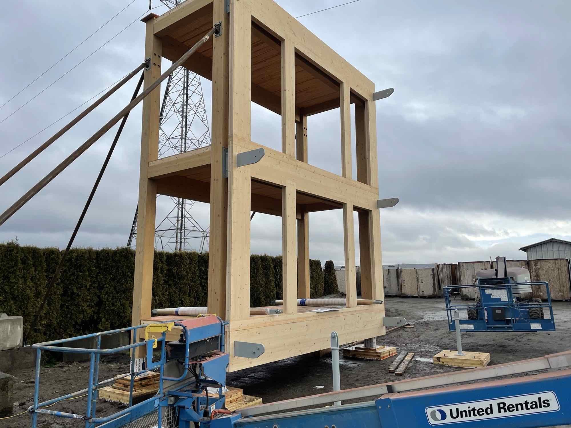
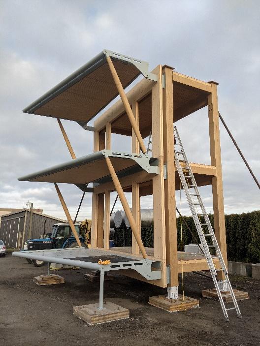
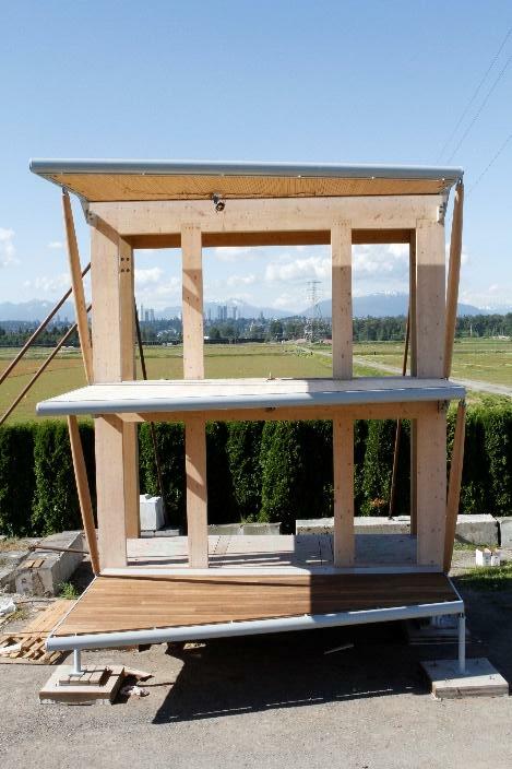
The balcony mock-up design is based on Canada’s Earth Tower, a proposal to create a 38-storey, 31,494 square meters (340,000 square foot) high-performance mass timber residential mixed-use sustainable development targeting Passive House certification. This research project has selected a two-story balcony structure from Canada’s Earth Tower design proposal to use as a prototype to design and construct with a focus on investigating key research questions identified in the ‘Introduction‘ section of this report. While this is not a comprehensive comparison or examination, the balcony mock-up studied what it means to have a face-mounted, projecting and thermally broken timber balcony system to a glulam primary mass timber structure through a unitized CLT wall panel.
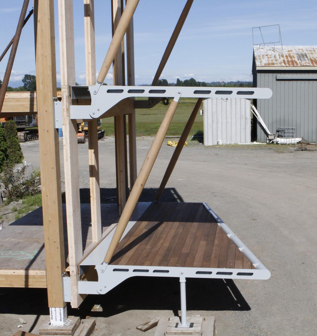
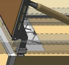
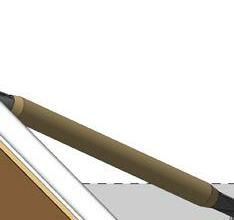
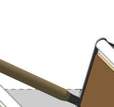
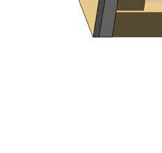
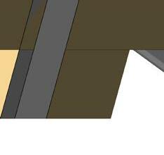
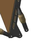
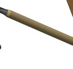
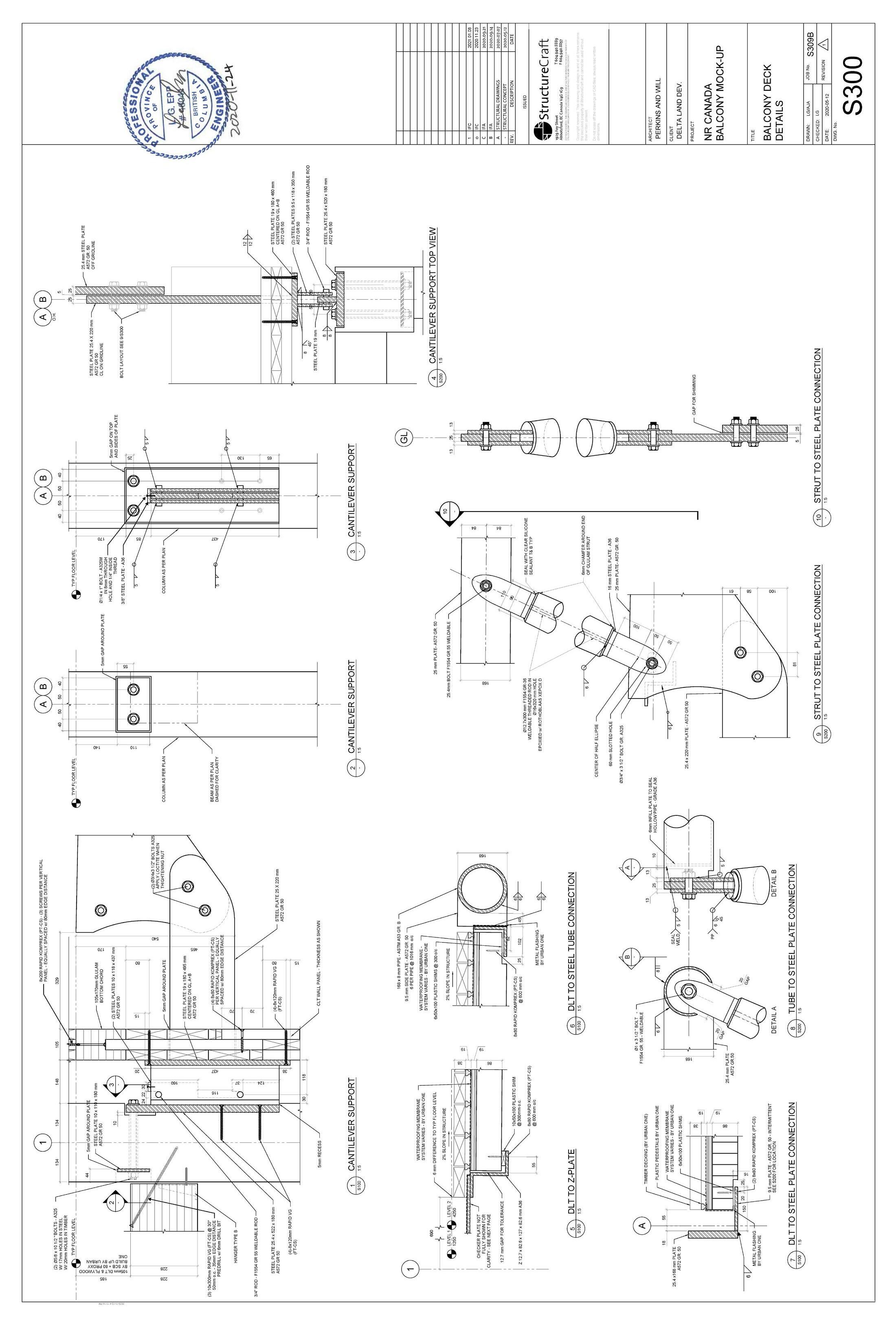
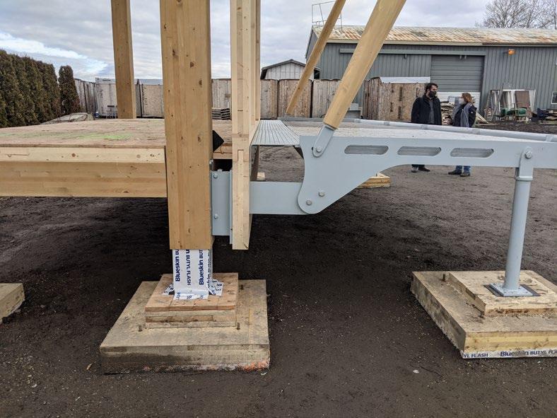
The balcony structure was designed to utilize a steel and timber hybrid strut that acts in two ways: in compression under normal loading, and in tension to counteract wind uplift. The balcony decks are supported by two custom steel plates at the inner corners, and by the timber compression struts at the outer corners. Steel knife plate connections combined with compression struts work together to simplify the envelope detailing, and minimize the extent of the envelope penetration and thermal bridging, which can be further improved with the use of a thermally broken connector. The compression member prevents the balcony from buckling at the steel connections and reduces the size of the structural connection back to the building’s primary structure.
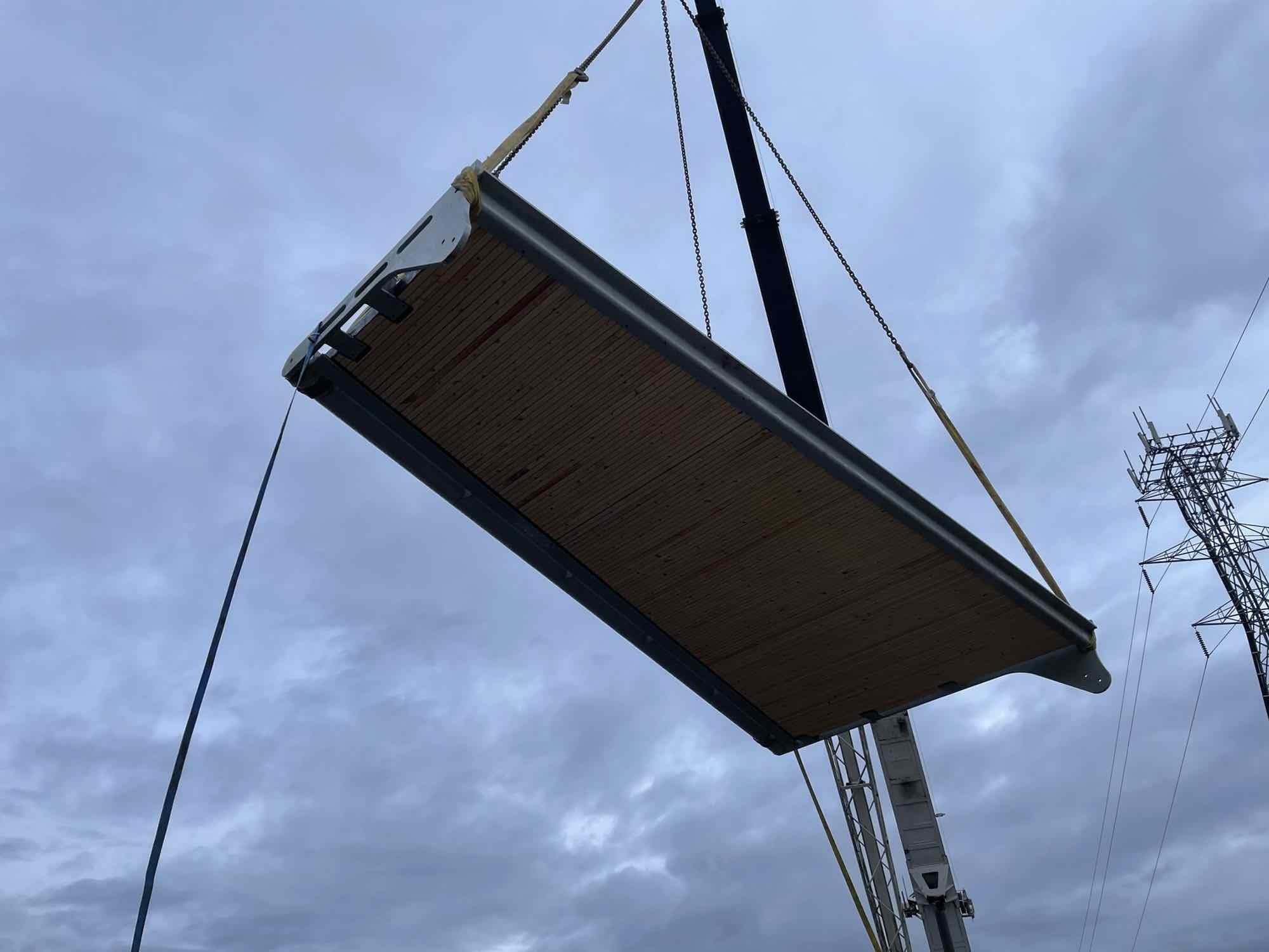
The balcony decks are prefabricated from the combination of a structural steel frame, exposed mass timber struts, dowel laminated timber (DLT), and cross-laminated timber (CLT) decks, and explore two types of waterproofing membranes as well as two types of finish decking material. Balcony decks come as a prefabricated modular unit to accelerate construction speed while minimizing construction waste and ensuring superior quality assurance and control. Unlike conventional balcony construction with a simple floor slab extension, the mock-up explores dissociation of the interior floor structure from the balcony through the steel connection details and allows for the height of the balcony to be designed to minimize the stepover height and to accommodate a zero-threshold condition.
Building code requirements and industry standards related to mass timber construction are continuously evolving and being updated. Overall, the balcony mock-up research and process demonstrates the viability of thermally broken balcony solutions in mass timber wood buildings.
This report was produced by Perkins&Will Canada Architects for Delta Land Development. We gratefully acknowledge the support of the Government of Canada.
Aik Ablimit, Perkins&Will
Mona Lemoine, Perkins&Will
Reviewers:
Alysia Baldwin, Perkins&Will Cillian Collins, Perkins&Will Elton Gjata, Perkins&Will Marc Haberli, Perkins&Will Clive Lewis, Perkins&Will Kathy Wardle, Perkins&Will
Aik Ablimit, Perkins&Will Elton Gjata, Perkins&Will Jake Jellis, Perkins&Will
Graphic Design:
Babak Manavi, Perkins&Will Karena Yeung, Perkins&Will
Acknowledgment is extended to the following industry leaders who contributed to the design and construction of the balcony mock-up: Kirk Robinson, Delta Land Development
Deanna Yue, Delta Land Development Andrew Harmsworth, GHL Consultants Ltd
Sean DeWinter, GHL Consultants Ltd Harrison Glotman, Glotman Simpson Levi Stoelting, Glotman Simpson
Graham Finch, RDH Building Science Inc. James Higgins, RDH Building Science Inc.
Jordan Bordignon, StructureCraft Lucas Epp, StructureCraft Lukas Gispert, StructureCraft Brandon Sullivan, StructureCraft Brent Olund, Urban One Matthew Wollin, Upper Canada Forestry Products
Thank you to the following industry partners for providing decking materials and supports: Upper Canada Forest Products Accoya—Accsys Technologies Swift Sure Milling Ltd.
Canadian Bavarian Millwork & Lumber Ltd. ThermalWood Canada
Thank you to Sansin for providing KP-12 wood coating products.
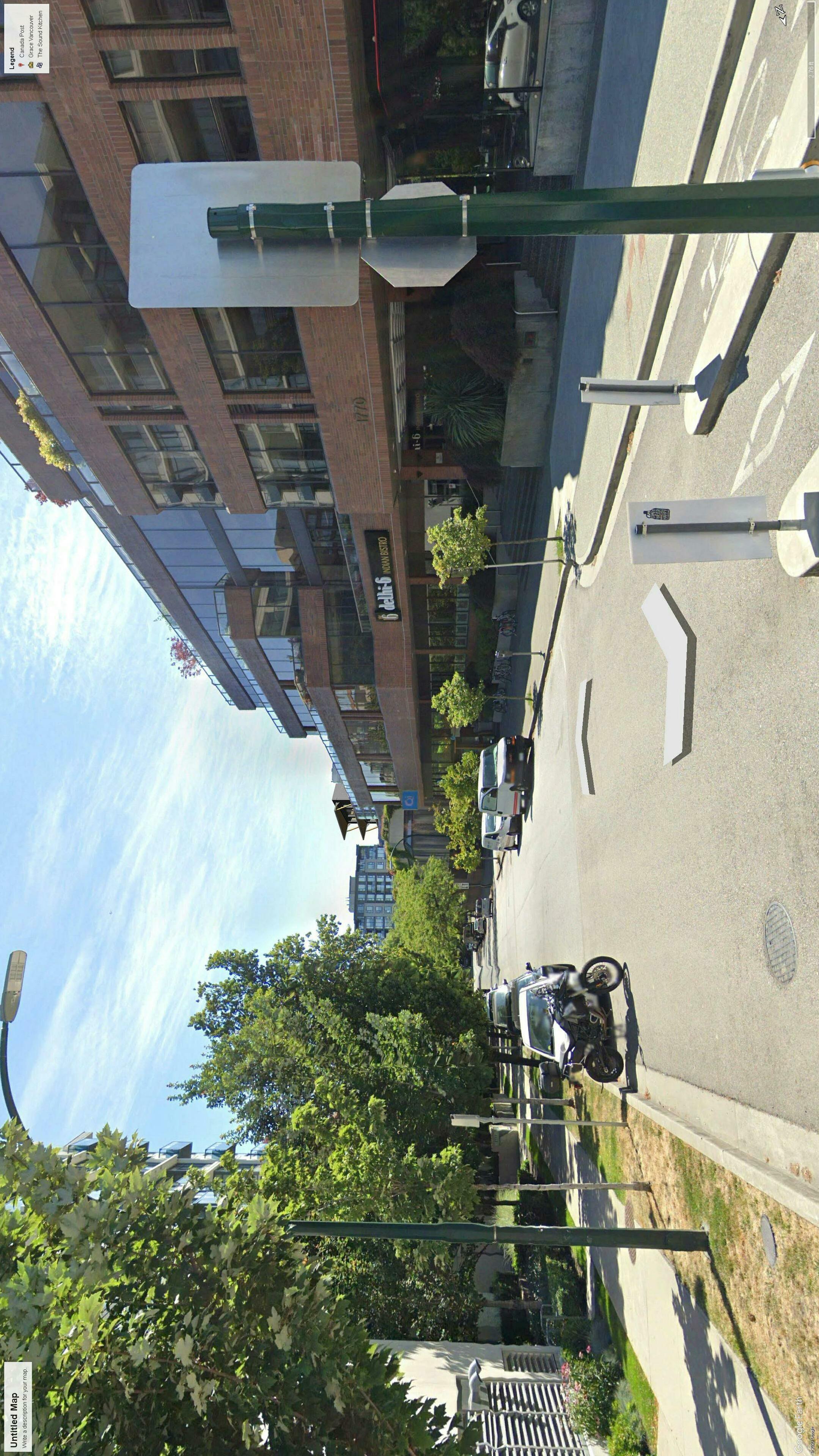
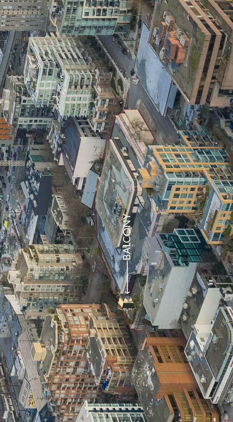
A special thank you to the Richberry Group of Companies’ for the use of their property.
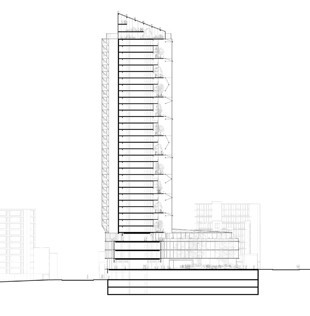
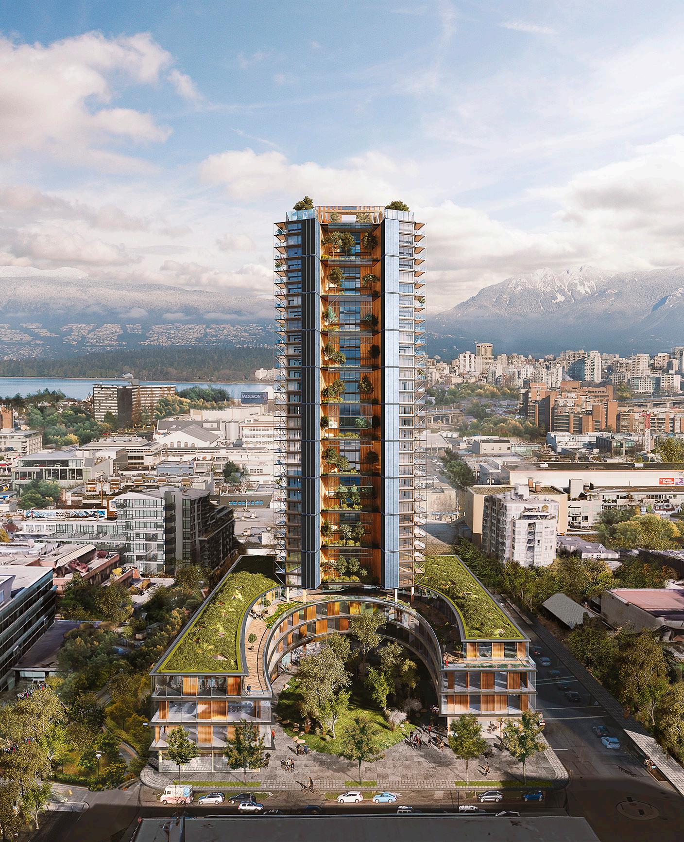
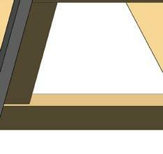
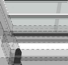
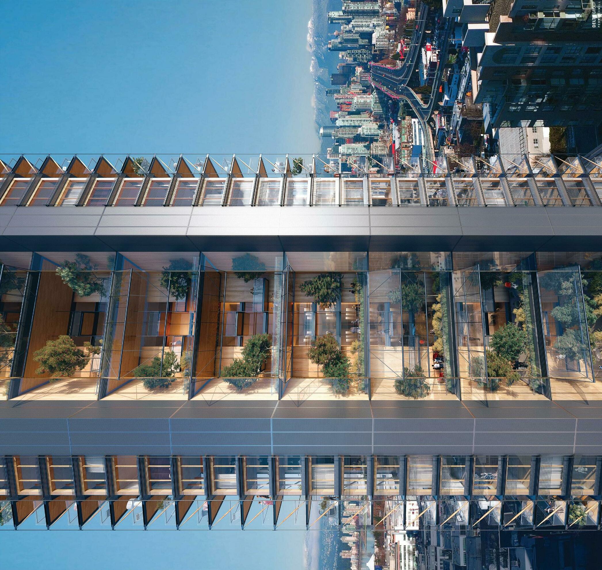
Located in the heart of Vancouver, Canada’s Earth Tower design proposal is in the rezoning phase to re-envision the third largest C-3A-zoned site in the City of Vancouver. It is proposed to create a 38-storey, 31,494 square meters (340,000 square foot) residential mixed-use highperformance sustainable development, constructed using mass timber with a target of achieving Passive House certification. This 38-storey building consists of three storeys of below grade parking, a six-storey mixed use podium, including office, retail and residential tower above, as conceptually illustrated in Figures 1 and 2. The podium is designed to incorporate mass timber columns and other wood based elements and the residential tower is proposed as a concrete core with a mass timber structural frame (Figures 3 and 4). It is set to exceed Mjøstårnet in Brumunddal, Norway, currently the tallest modern wood building in the world.
Fundamental to the project is demonstrating an approach to urban development that prioritizes meaningful initiatives to address humankind’s impact on climate change. Equally important, is to bring focus to the influence materials have over the health and well-being of the inhabitants, and the implications to the ecosystem that result from their creation. In pursuit of these two objectives, the use of wood is critical, with its capability to address greenhouse gas (GHG) emissions in a meaningful way. By employing wood as the primary structure, the proposed development will advance the industry by altering market perceptions, providing choice, prioritizing performance, and minimizing the environmental impacts.
 Figure
Figure 3: Canada’s Earth Tower Winter Garden View Looking North—with a series of suspended balconies at each end of the residential tower

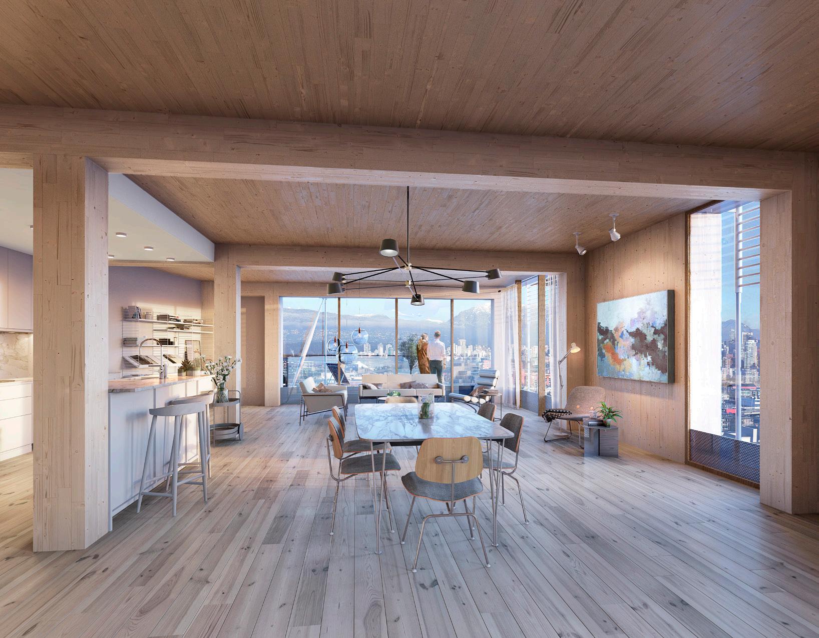
Figure 4: Canada’s Earth Tower Interior View—showing mass timber structural members with timber balcony in the background
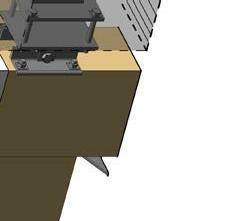
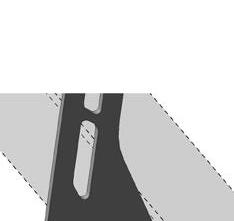
As a critical design component in residential buildings, balconies pose significant challenges for the successful execution of competing structural, fire and thermal requirements. These challenges are amplified in mass timber construction due to added new design difficulties regarding structural connections, building enclosure detailing, and proper waterproofing membrane application. Due to limited budgeting and given the repetitive nature of the balcony layout, this research project has selected a two-storey balcony structure from the Canada’s Earth Tower design proposal to use as a prototype to design and construct (Figures 5-8). The prototype will be used to analyze, document, and better understand its performance in a real world setting regarding thermally broken structural connection detailing, off-site timber pre-fabrication, and weather protection.
Conventional strategies, in concrete or steel buildings, predominantly include projecting and inset balconies that are supported through direct extension of the floor structure. Although these conventional balcony construction methods provide a cost effective solution, the associated thermal bridging cannot be ignored as the increasingly stringent building energy requirements, i.e., the BC Energy Step Code, are introduced to achieve high-performance buildings with reduced carbon footprints. In tall mass timber buildings, the requirements to connect balconies to the structure and related building enclosures are relatively new and evolving. It comes with its own challenges. Perkins&Will and the design and construction team were commissioned to design a balcony mock-up that would overcome barriers, and provide solutions to address structure, durability and constructability for balconies in mid to high-rise mass timber buildings will improve the acceptance of timber as a competitive structural system.
nj
nj
The focus of this balcony mock-up research is to:
Balcony Mock-up: Structural Design
Investigate the use of timber as a structural material in a thermally broken balcony system—mass timber primary loading bearing structure, timber strut, timber deck, and timber unitized envelope system.
Evaluate balcony structure and materials for compatibility with timber building structure, considering weight, durability, and ease of construction.
Balcony Mock-up: Deck Finishes
nj
Test different types of engineered wood as decking material, exposing the underside of the engineered wood structure with a durable and clear coating, while maintaining a zero-threshold.
Balcony Mock-up: Durability & Weathering
nj
Investigate durability and weathering. Install moisture monitoring sensors on the mock-up to log the moisture characteristics of the balcony timber components.
nj
Devise connection details to building structure that adequately accommodates all loads while enabling effective completion of a high-performance building enclosure.
Balcony Mock-up: Thermal Performance
nj
Investigate the method of transferring load from the thermally broken balcony to the primary structure through the unitized cladding system.
Balcony Mock-up: Constructability
nj
Evaluate constructability, methods of construction sequencing of the prefabricated balconies to avoid temporary scaffolding and bracing, and opportunities for prefabrication to support the broader goals of efficient and quick completion of the building envelope.
nj
Investigate a zero threshold (no more than 13mm) balcony condition to accommodate universal accessibility.
nj
Mock-up and monitor the performance of two different types of timber balcony decks, i.e. dowel laminated timber (DLT) and cross-laminated timber (CLT), and two different membrane combinations, i.e. two-ply styrene-butadienestyrene (SBS) and a urethane membrane. Understanding the penetration of water through balcony edge details to explore how the final structure will handle water.
Balcony Mock-up: Code & Bylaw Acceptance
nj Investigate Code and Bylaw requirements related to climbability and occupant safety, acceptability of mass timber as decking material and fire rating requirements.
Balcony Mock-up: Cost Effectiveness
nj Evaluate cost effectiveness of prefabricated balconies.
nj This research supports the following Government of Canada goals/directive/vision:
The broader adoption and commercialization of wood-based products in the construction of high-rise buildings;
‒ The replication of demonstrated wood-base buildings; and
‒
Canada’s transition to a more wood-inclusive construction industry.


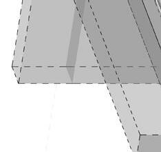
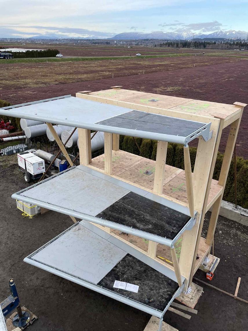
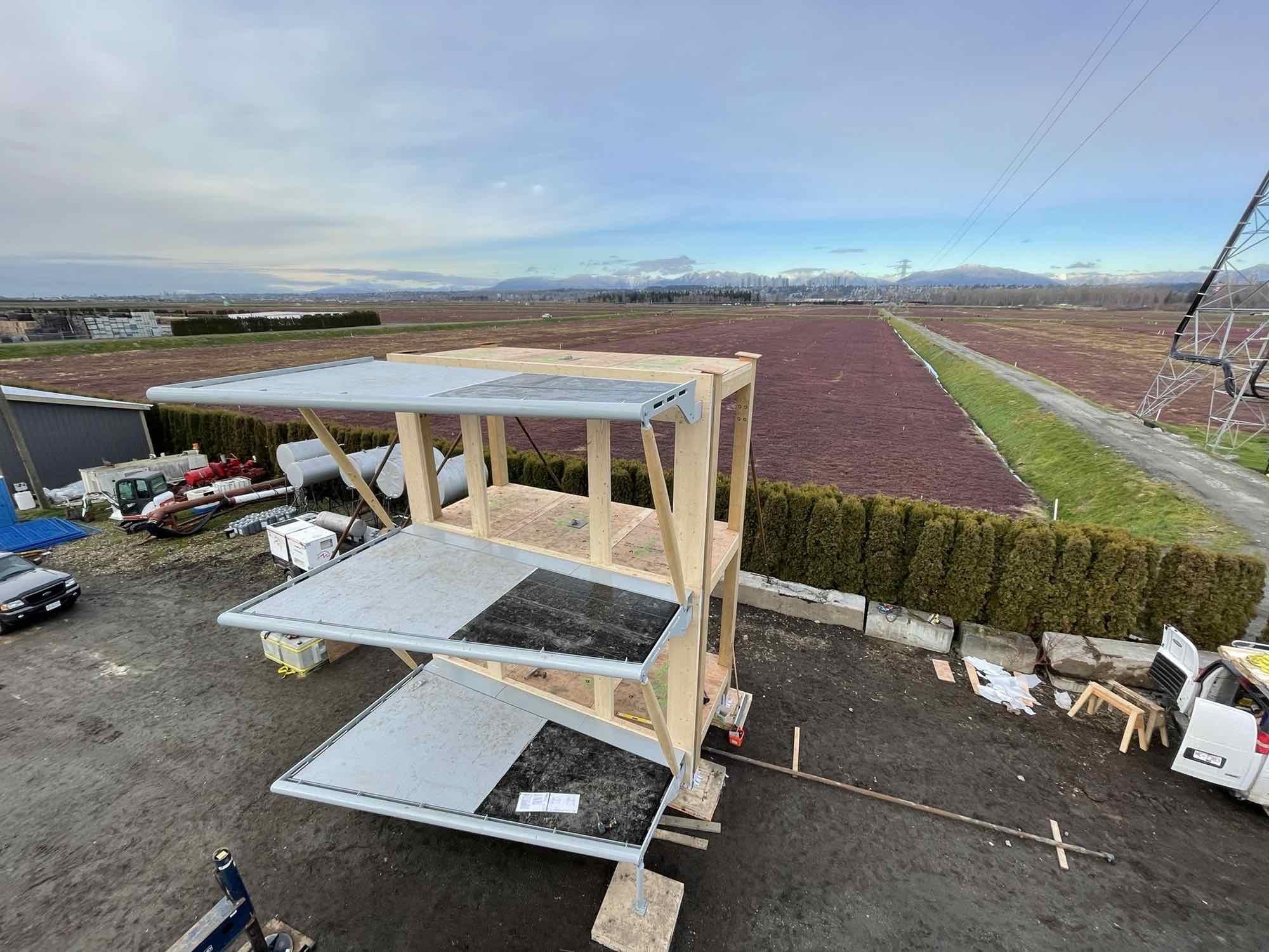
Figure 7: Balcony mock-up front and side elevations illustrating attachment of prefabricated balcony modular units to the unitized envelope system.
Figure 8: Balcony mock-up front and side sections showing a level zero threshold condition to allow accessibility.
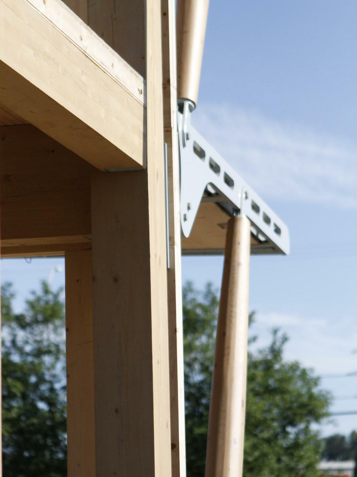
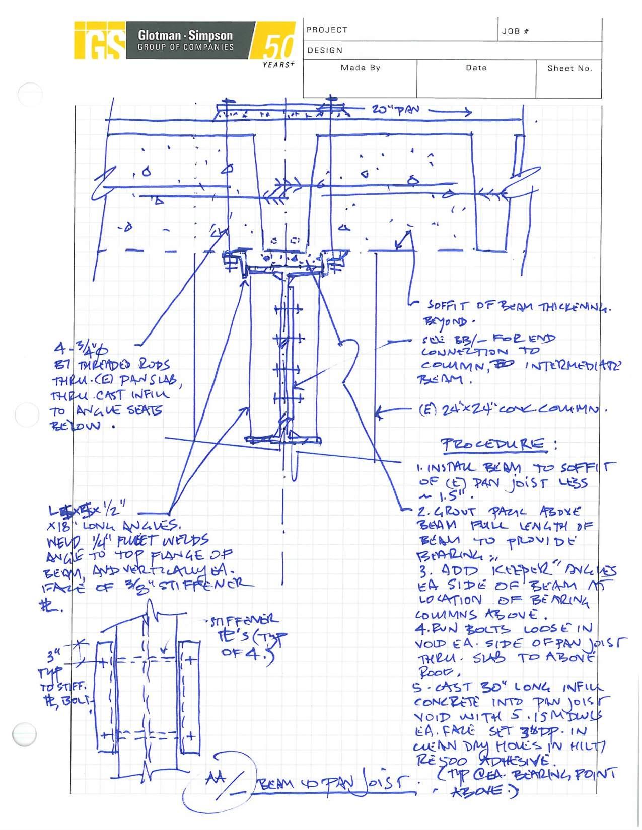
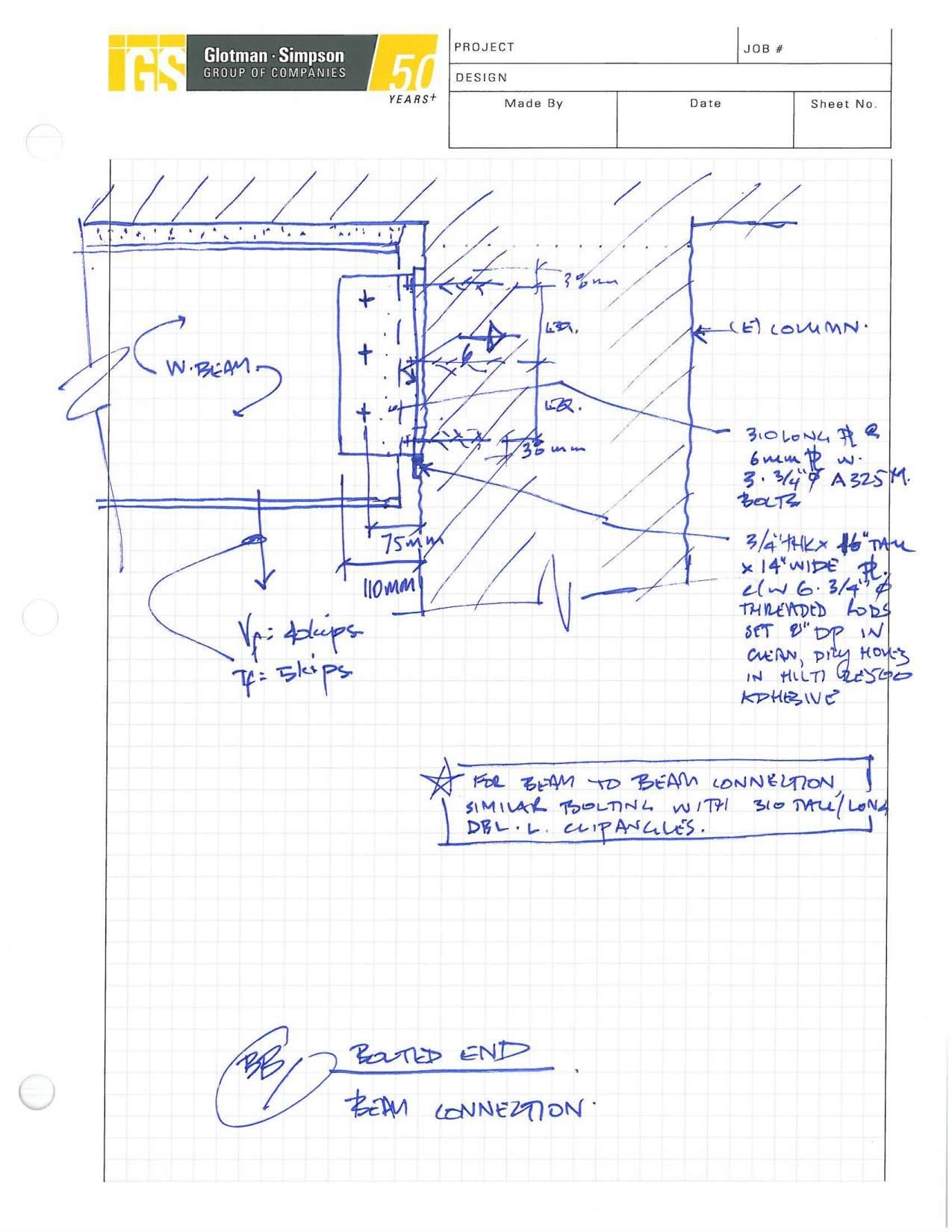
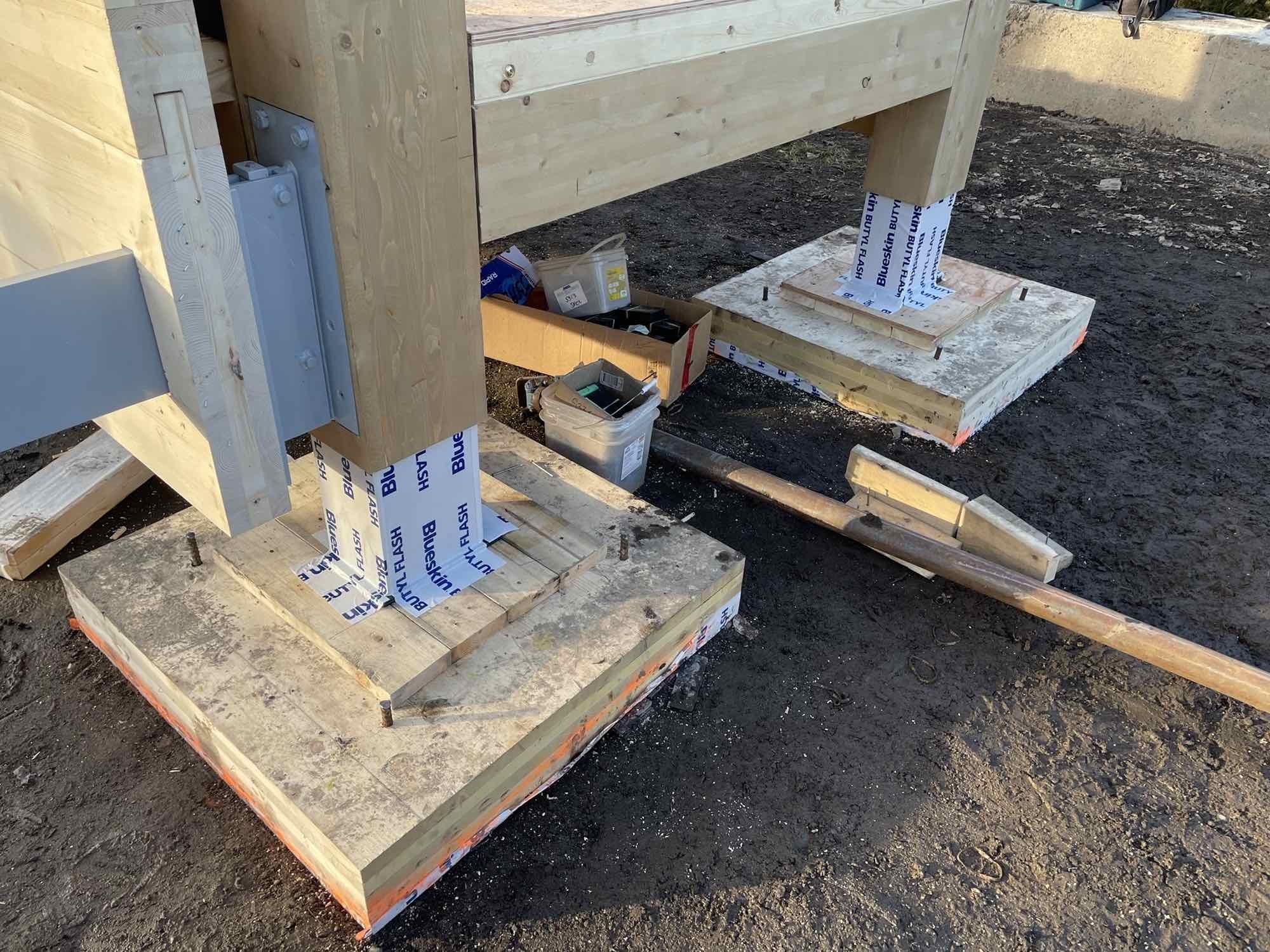
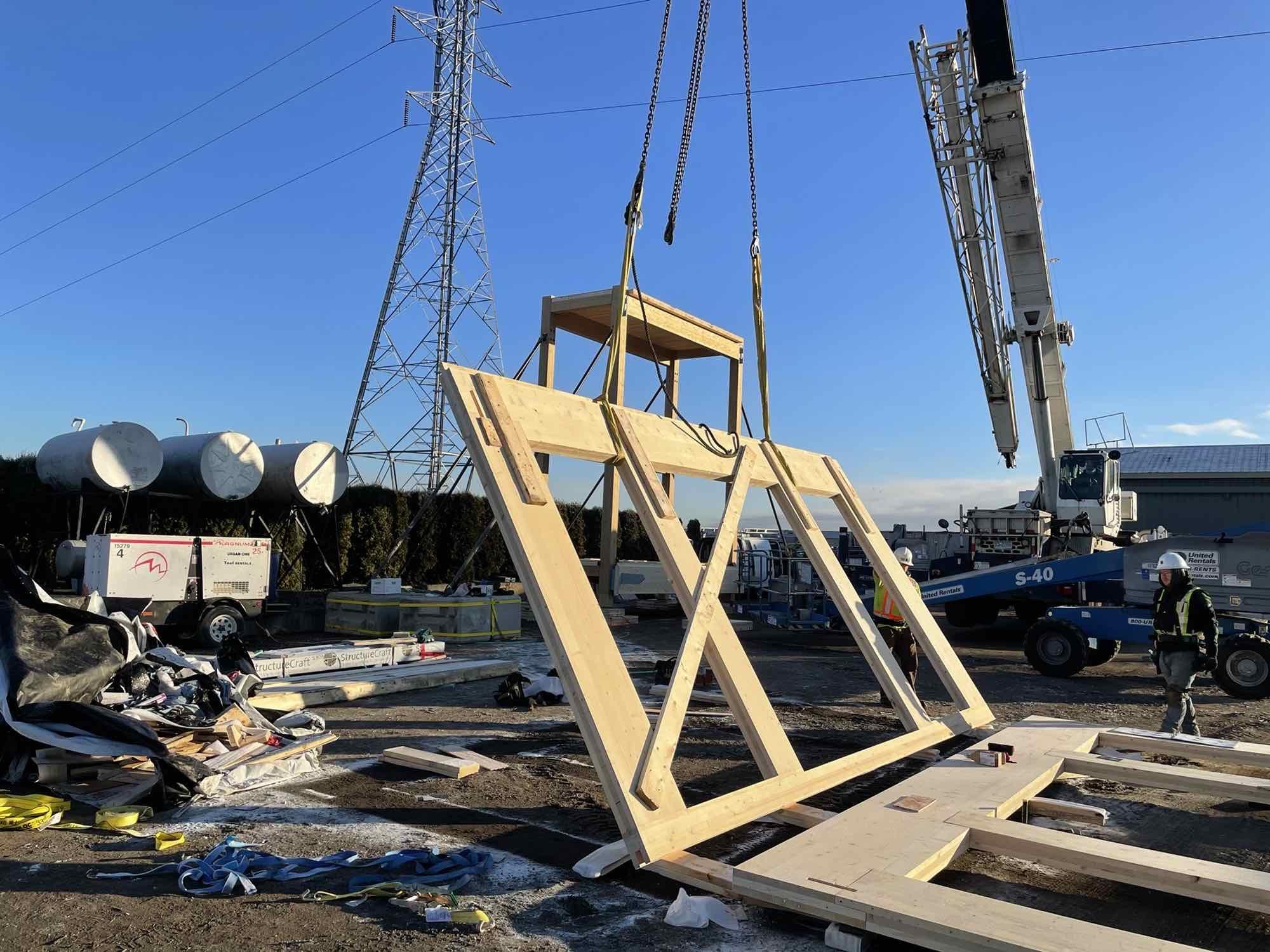
As part of Canada’s Earth Tower multi-story residential mass timber development, the original design concept initially utilized steel tension rods at the balcony corners, largely based on design aesthetics. However, further structural engineering review revealed concerns about structurally linking all the balconies together and hanging them from the roof of the building. Linking the balconies together in the way initially intended would transmit sound or vibration among all the balconies, while making maintenance difficult. In addition, the transition from steel tension rods to a steel and timber hybrid compression strut takes advantage of timber’s inherent compression strength. While maximizing the timber components, it allows for the floor projecting system that collects the balcony outriggers to serve double duty as the anchor point receiving the timber compression strut.
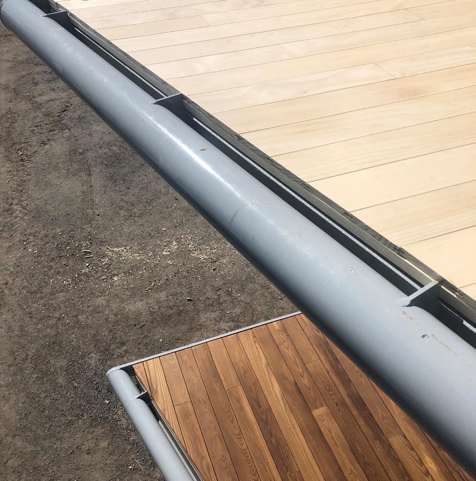
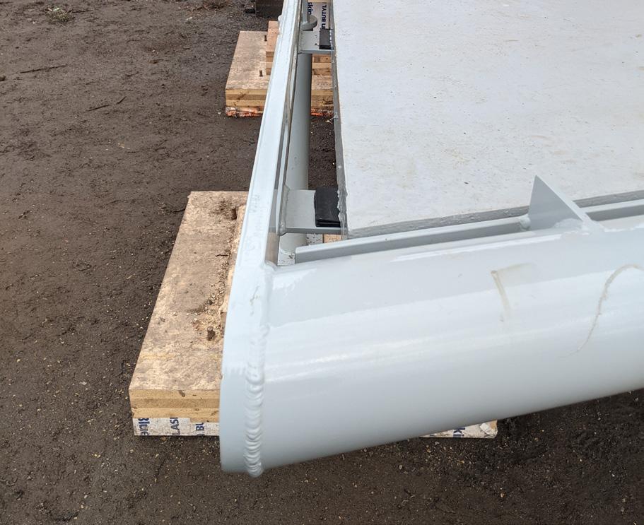
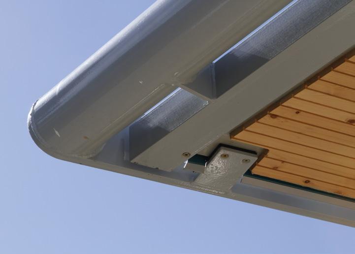
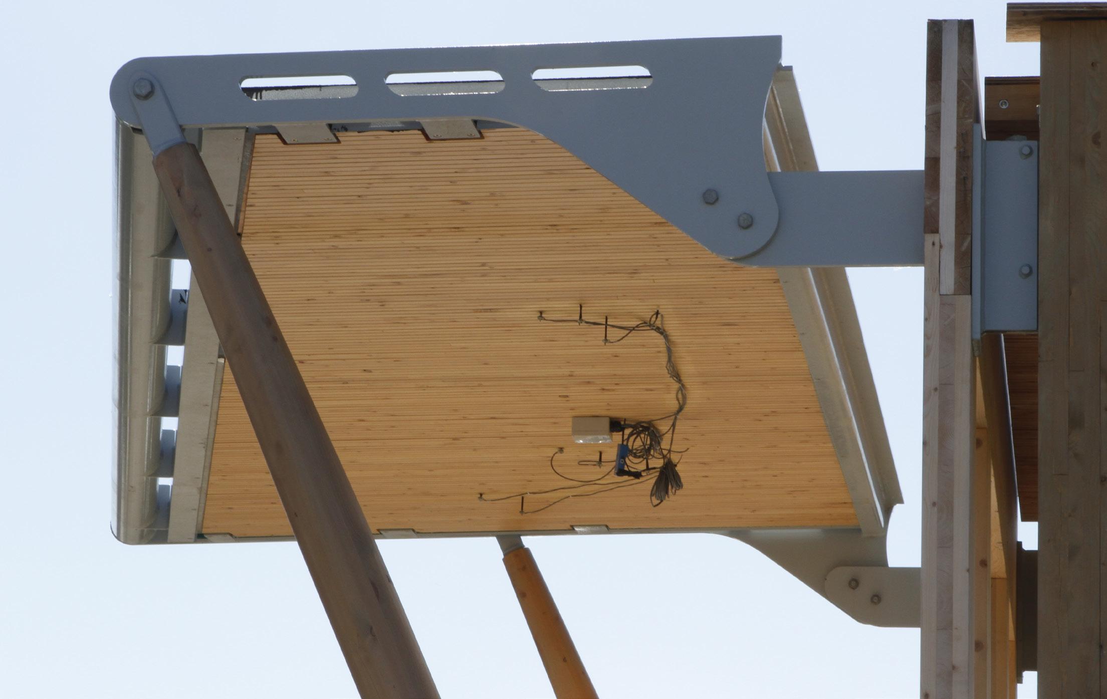
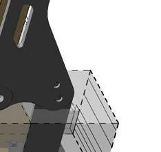
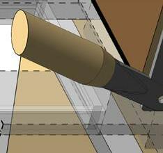
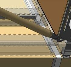
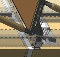
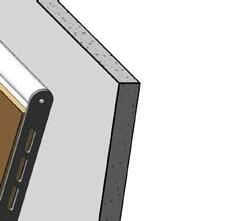
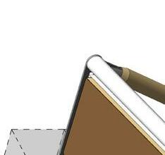
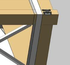
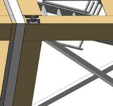
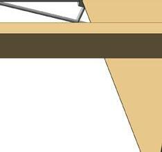
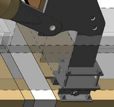
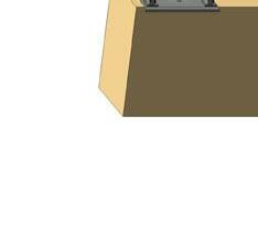
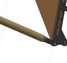
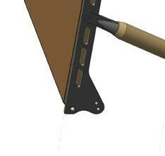
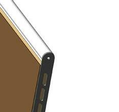
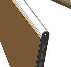
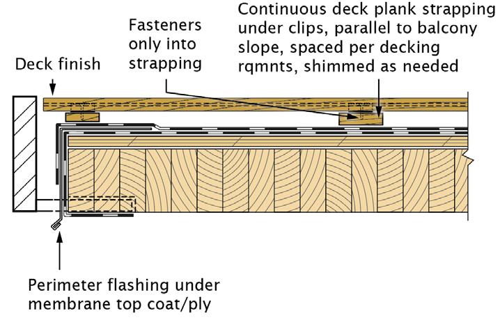
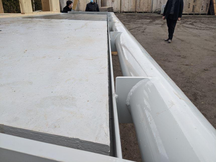
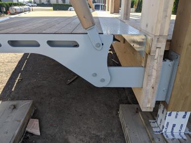
To significantly reduce the thermal energy transfer between indoors and outdoors while aligning with Canada’s Earth Tower’s concept proposal design intent, a face-mounted or projecting balcony system through discrete connections and compression members was ultimately selected for the balcony mock-up. The balconies are supported off the primary structure with a discrete steel connection at the inner corners of the balcony and from below by the compression struts at the exterior edge. The compression member prevents the balcony from buckling at the steel connections, while reducing the size of the structural connection back to the building’s primary structure. The balconies were fabricated from a combination of structural steel members, exposed timber glulam struts, and CLT/DLT decking, coupled with decking finish and installed once the building envelope is complete (Figure 9).
The balcony structural design was to utilize a steel and timber hybrid strut that acts in two ways: in compression under normal loading, and in tension to prevent wind uplift. Two discrete steel plate connections support the balconies at the inner corners, and with two compression struts supporting the exterior corners. A custom steel blade connection at each end of the balcony back edge adjacent
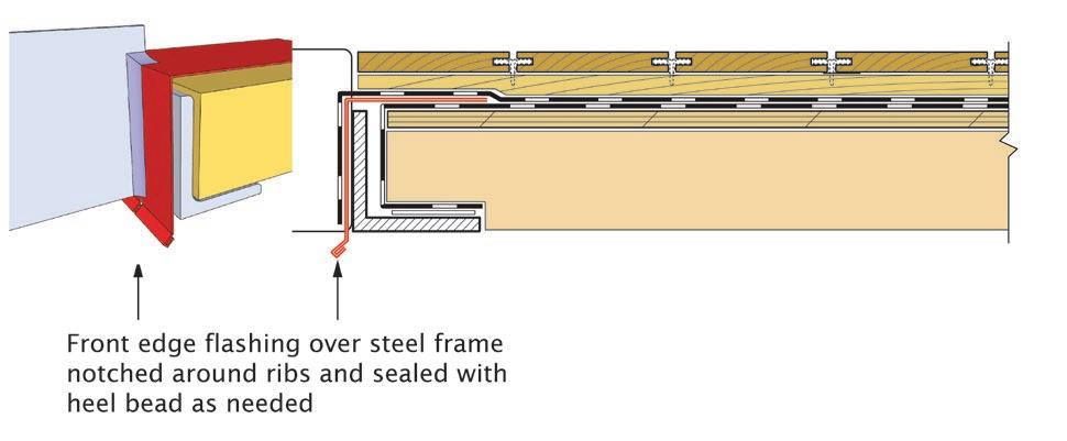
to the building envelope, was proposed to simplify the envelope detailing, while minimizing the extent of the envelope penetration and thermal bridging.
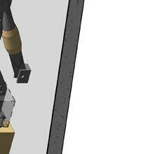
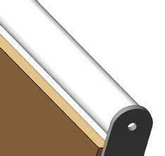
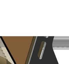
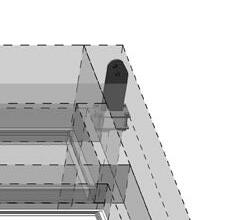
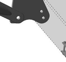
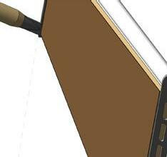
The chosen structural strategy also considered the construction sequencing and installation. The custom steel blade connection comes in two parts. The first component is affixed to the primary structure and serves as a hanger for the cladding panel. The second component is prefixed to the cladding panel and includes the penetrating blade connection where the balcony ultimately connects (Figure 10). The connection includes adjustment and set screws for tuning and leveling during site deployment. While it is unique, the custom steel blade connection was designed based on several factors:
nj Independent balcony framing to maintain continuity of cladding, to ease installation sequencing, and to reduce thermal bridging.
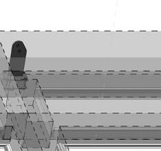
nj Prefabricated facade installation that would allow for the cladding installation, independent of the balcony installation, accommodating the separate construction of facade panels and the balcony structure, while maintaining the continuity of the thermal control layers at the interface (Figure 11).
nj
The offset length of the connector which is based on cladding width, the forces applied at the discrete point, and the connection back to a timber column substrate led to a custom solution that served the project’s specific purpose. There was not a readily available proprietary product that would have sufficed in any efficient way in this case.
nj
To provide the ability to tune and adjust both the balcony and the unitized cladding system in order to achieve optimal alignment and seal during erection, while minimizing the required tolerances.
nj
Overall loading and span requirements of the balcony, coupled with consideration of a structural thermal break (Figure 12).


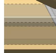
In addition to fenestrations in the building envelope, balconies are often one of the weakest areas in the residential buildings when it comes to thermal bridging. Depending on the type of structural connection, thermal performance of the balcony connection detail can have a sizable impact on the overall building performance. Conventional solutions, such as direct extension of floor structure in concrete or steel buildings, are known to be a less effective way of mitigating thermal bridging.
Understanding that Canada’s Earth Tower is designed to achieve a Passive House standard that has one of the most stringent energy targets, it requires an air-tight high-performance envelope system coupled with a unique approach to the balcony connection. While conventional industry standard methods do not lend themselves to achieving the stringent thermal performance required for the project, as part of the balcony mock-up the connection detail of the balcony to the building primary structure was custom designed to minimize thermal bridging, while keeping the overall design intent.
Interior CLT Floor w/Concrete Topping
Glulam Column Primary Structure

Balcony Lower Bracket (Built in Glulam Column Primary Structure)
Continuous Air & Vapor Barrier


Balcony Upper Bracket (Built-in Module Unitized Envelope System)


Sheet Metal Flashing Module Unitized Envelope System
Stopping


x 32mm Steel Plate
dia. Balcony Glulam Pole Strut
Structure
Unitized Envelope System


Connection Bracket
Glulam Column Primary Structure)
Connection Bracket (Built-in Module Unitized Envelope System)
x 32mm Structure Steel Side Plate

dia. Balcony Glulam Pole Strut
dia. Steel HSS Pipe
The size and number of the connection points back to the primary timber structure were reduced by the addition of timber strut compression elements. Although further thermal analysis would be helpful to quantify the relative reduction amount, as a rule of thumb this reduction in size and number of structural connections represents a significant reduction in thermal bridging at the balcony connection. While maintaining structural integrity, the performance of this connection can be further improved with the use of a thermally broken connector.
As opposed to face-mounted prefabricated balconies, the conventional balcony construction approach through on-site concrete slab or floor structure extension has its merits and is still favored by many developers due to lower upfront construction cost and trade familiarity. However, it is increasingly scrutinized due to poor thermal performance as a result of thermal bridging. Off-site balcony fabrication with a discrete balcony connection detail provides efficiency in balcony construction and sequencing by allowing the completion of the building enclosure prior to installation of the prefabricated balconies.
While the erection process of the balcony mock-up benefited from a high degree of prefabrication, balcony steel brackets that provide intermittent connections between the balcony inner edge adjacent to the building cladding and the building structure, must be coordinated in the primary structural design and construction. In addition, the intermittent connections help reduce the extent of penetrations in the thermal enclosure, but additional waterproofing details must be considered at intermittent structural connections to maintain the continuity of air/vapour barriers and to further mitigate the risk of water ingress.
The balcony system can be prefabricated off-site, including the waterproofing membrane, which provides protection for the timber deck while allowing a highly controlled environment to make challenging detailing work easier to execute. In addition, balcony prefabrication allows for flexibility in the shape and design, superior quality assurance, control in balcony construction, acceleration of construction schedule, and minimizing construction waste.
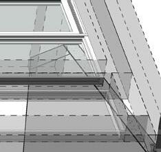
The off-site prefabricated balcony approach may simplify the alignment of the interior floor structure with the exterior balcony structure to minimize the height of the door threshold for accessible dwelling units. The threshold requirements should be considered in detailing the thermally broken balcony connection, in conjunction with the structural support for the door openings. Dissociation of the interior floor structure from the balcony through the steel connection detail allows for the height of the balcony to be designed to minimize step-over height and accommodate accessibility (Figures 13 and 16).
The accessibility requirement for the balcony mock-up dictated the final location of the balcony deck in relation to the interior floor surface. While the mock-up does not include actual windows or doors, the rough opening for the balcony access sliding door was detailed such that it would allow less than 13mm threshold condition while not compromising the thermal performance of the balcony connection (Figure 14). Special care should be given to the interface detailing to better sequence threshold door sill flashing and membrane termination. Also, structural steel connections and balcony detailing must accommodate differential floor-to-floor moment between the balcony and interior structure with regards to the membrane performance and differential thermal expansion and contraction.
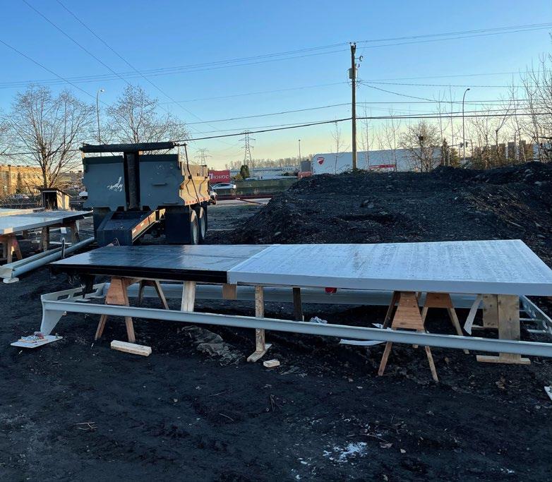
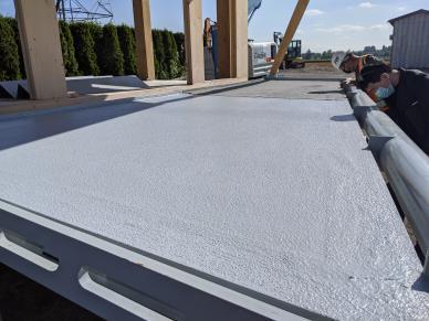
The balcony decks are prefabricated from a combination of a structural steel frame, exposed mass timber struts, dowel laminated timber (DLT), and cross-laminated timber (CLT) decks, that include a waterproofing membrane and finish decking material. The mock-up tested two different types of membrane—SBS and reinforced liquid applied PU, to assess how they would be compatible with the timber decking element. Guardrails are designed to be bolted on site in order to keep decks stackable and to facilitate transport. In the case of the mock-up, guardrails were not included for budgetary reasons, but design consideration around metal flashing and water-proofing membrane termination is of importance and dependent on how and where the guard support is attached to the balcony perimeter steel members.
One of the advantages of using timber is that it can be structural and used as a finish at the same time without needing a finish material over the timber. While it is safer to apply in indoor environments where there is better thermal control, it can equally be applied in the outdoor condition, acknowledging that proper and durable coating is periodically provided to enhance the serviceability.
Material honesty and exposing the underside of the balcony timber deck are important design considerations for Canada’s Earth Tower. As such, the balcony deck was designed and constructed with two timber materials, DLT and CLT, to test how it reacts to different weather membranes while meeting the structural loading requirements. Based on the supplier’s instructions, a clear finish coating was applied to the timber deck providing the necessary protection while keeping the wood grain that is essential to architectural honesty. The protective coating for the timber deck was applied on site once the timber had dried out after a few wetting and drying cycles. The wood had not weathered significantly prior to the coating application.
As construction of the mock-up took place during a relatively wet season, it would have been prudent to have a factory applied base coating before shipping the prefabricated balcony deck panels to site to avoid exposing the timber deck to excessive moisture. Once the installation was complete, the final clear coating should have been applied to increase timber durability. Additional follow-up will provide a holistic analysis on how the timber deck performs under the exposed outdoor environment.
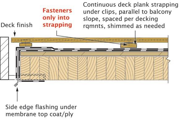
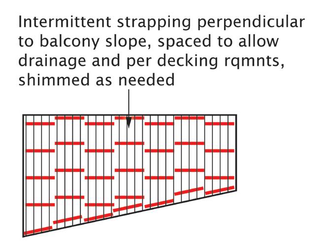
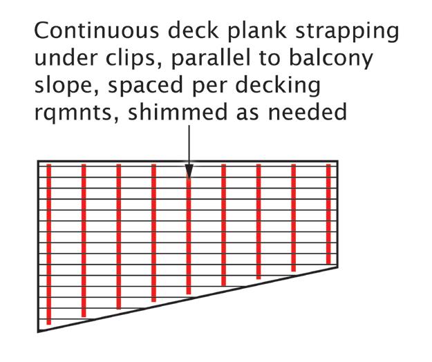
To examine performance and appearance of the finish decking, two different ways of running the finish decking boards were tested, the Accoya decking material was installed running perpendicular to the building envelope while the ash material was installed running parallel to the building facade (Figure 15). While the latter layout worked better as the support sleepers or strappings were continuous, running parallel to the water drainage slope, it created uneven interface conditions along the balcony front perimeter. The former layout resulted in a cleaner look along the perimeters, but a series of intermittent sleepers or strappings would be required to provide support while allowing undisrupted water drainage. How the deck finish is attached while maintaining the continuity of balcony roofing membrane, is a key consideration when planning for integration of decking finishes.
As there is an increasing demand on employing exposed timber members for architectural aesthetics in an outdoor condition, it becomes a critical necessity to provide protection that enhances timber’s durability and weathering. Coupled with finish coating that provides weather protection for balcony timber members, careful selection and installation of balcony membrane is required to provide long-term moisture protection and proper balcony edge detailing to reduce the risk of water ingress into the wood components.
Figure 15: The ash decking material (lower) running parallel to the building enclosure face and the Accoya decking material (upper) running perpendicular to the building facade.Two different types of membrane, two-ply styrenebutadiene-styrene (SBS) and a urethane membrane, were tested to investigate and understand the performance of how each membrane behaves to provide protection on DLT/CLT timber decks’ durability and weathering (Figure 24). Moisture monitoring sensors have been strategically placed on underside of the deck to monitor and log data of characteristics change of the timber decks. Further analysis in the post construction evaluation report will be shared.
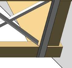
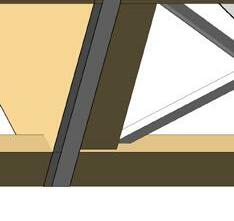
While accommodating overall structural loads, all diagonal members must be designed to meet local code requirements regarding climbability and occupant safety. To mitigate issues with climbability, the balcony frame was designed to accept the struts outboard of the guard (Figures 14 and 17).
This balcony mock-up has applied an interpretation to apply the mass timber diameter criteria to the struts from Table 3.1.7.1. This interpretation was made as there is structural fire-resistance rating required for these elements and there is no minimum diameter for Encapsulated Mass Timber Construction (EMTC) elements provided in Table 3.1.18.3 where only rectangular EMTC dimensions are provided.
Although it is not installed in this mock-up, sprinklers are required for all EMTC building balconies, even if they are noncombustible, when they are over 610mm in depth based on current BC Building Code and Vancouver Building Bylaw 2019. This is based on a concern with vertical fire spread in EMTC buildings at the exterior. Recent fire demonstrations involving exposed CLT compartments has provided data that supports the potential for a code change to relax balcony sprinkler criteria in EMTC buildings.
Cost savings may be realized through the use of prefabricated balconies, but costs for the use of a hoist or crane to install the balconies must also be considered to have a meaningful comparison with other balcony construction solutions. Depending on specific project requirements, on high-rise projects the tower crane is normally kept to 6-8 weeks beyond the topping out of the primary structure; in this case the addition of the balconies as prefabricated items and requiring crane lifts may or may not significantly increase that duration. The total cost of incremental crane lifting to hoist all prefabricated balconies for Canada's Earth Tower would require additional analysis to determine exact amount.
While it is challenging to do a detailed ‘apples to apples‘ cost analysis at this prototype stage, our preliminary cost analysis indicated that the cost per square feet for this balcony mock-up is higher, comparing it to the conventional solutions constructed out of concrete or steel. However, this cost analysis does not holistically reveal full life cycle cost effectiveness of a prefabricated timber balcony construction solution. Environmental cost, such as carbon emissions of using timber versus concrete or steel and locally sourced materials versus outsourced ones, should be given equal consideration when assessing the overall cost effectiveness.

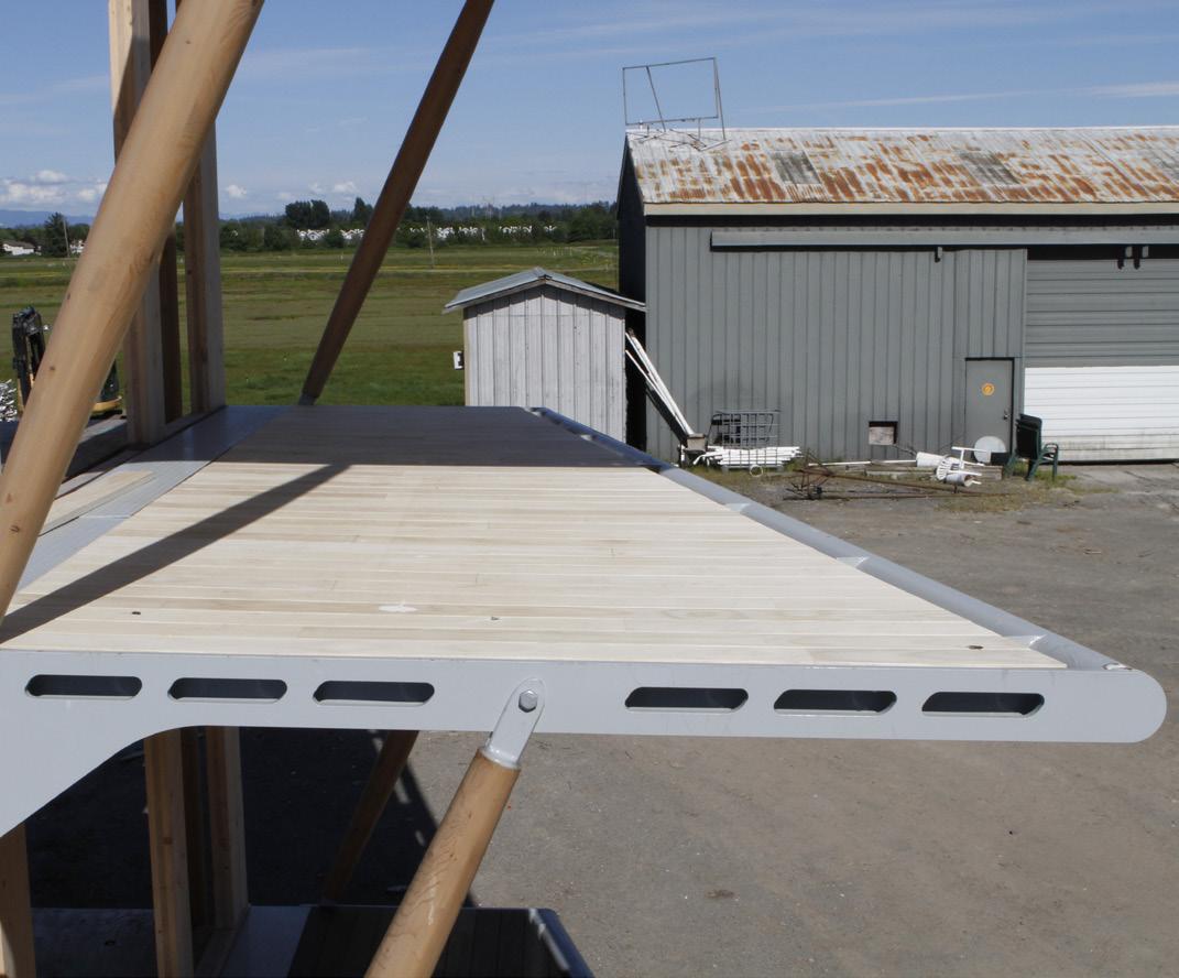 Figure 19: Balcony decking finish with ash decking material at the top and Accoya at the bottom of the balcony
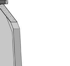
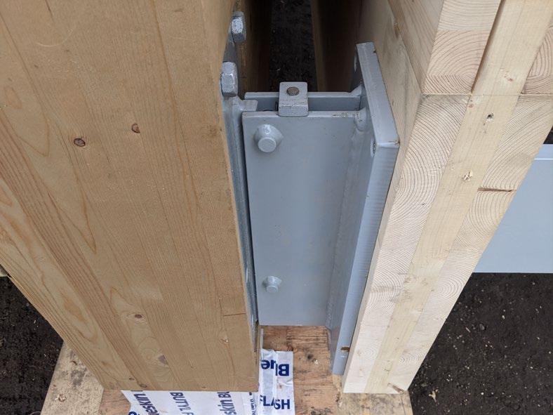
Figure 18: Custom steel connection through the unitized wall panel allows flexibility in adjusting the balcony height to address zero threshold condition.
Figure 19: Balcony decking finish with ash decking material at the top and Accoya at the bottom of the balcony
Figure 18: Custom steel connection through the unitized wall panel allows flexibility in adjusting the balcony height to address zero threshold condition.
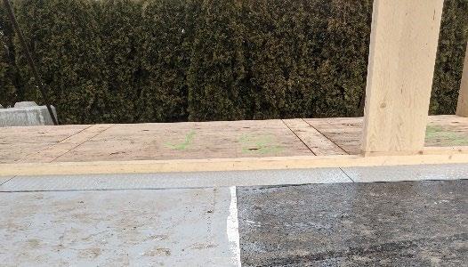
Figure 20: On-site construction progress photo showing the custom steel connection between the balcony and glulam primary structure through the CLT wall panel.
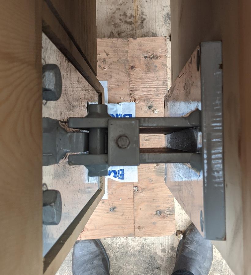
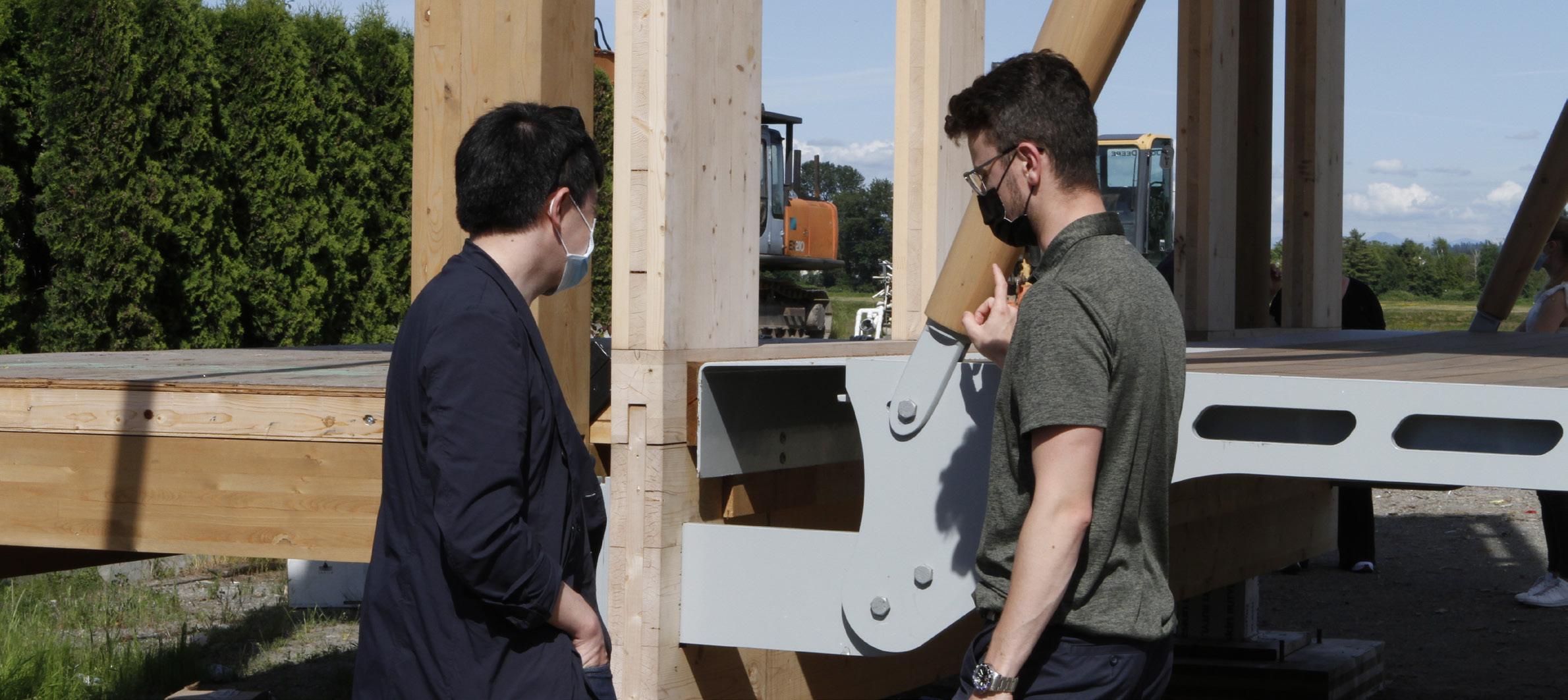
Figure 21: Balcony mock-up onsite progress with prefabricated balconies at two upper levels being put in place.
Figure 22: Balcony CLT/DLT support deck with SBS membrane applied, awaiting to be dried prior to placement of finish deck and support.

The balcony mock-up research investigated 11 key questions outlined in the introduction. While it is not an exhaustive investigation, the balcony mock-up process identified a number of key themes around which the lessons learned section is organized.
While the balcony connection approach utilized in the balcony mock-up is proven to have a potential for scalability for large applications, additional structural analysis and coordination is required to design and locate custom steel connection plates in the unitized envelope system and primary structure to support balcony structural elements. Bolted or welded structural connections must be carefully detailed to prevent risk of water ingress and may require periodic inspection.
One of the key study areas is durability of the balcony-towall interface and balcony components. While the balconyto-wall interface is critical for overall building enclosure durability, the mock-up focuses on the balcony assembly itself. Mass timber—DLT/CLT balcony support materials in the case of this mock-up—tends to slow not only the flow of
water vapour across the floor assembly, but also the drying process. As such, keeping the timber elements, especially those in the outdoor environment, in a desired moisture level across the life span is important.


As critical as balcony structure durability is, it is important to understand the thermal performance of a balcony connection design and its related impact on meeting increasingly stringent federal, provincial, and municipal building performance requirements. To do so, the balcony design must consider the context of the overall building performance. Thermal bridging needs to be mitigated especially when there are a high number of balcony connection points that penetrate the building thermal enclosure and weaken the overall building performance. It’s critical to reduce the extent and number of connection points between the balcony and the building’s thermal enclosure by strategically designing the size and shape of the balcony with minimal thermal envelope penetration in mind. It is key to consider structural thermal isolation in the connection details to reduce thermal bridging (Figure 23).

When it comes to thermal performance of a balcony system, off-site fabrication of the balcony with a discrete custom connection detail (Figures 23 and 24) to the building structure tends to do a much better job than the conventional slab extension approach. The prefabricated balcony modules are manufactured with greater precision than on-site construction, but the coordination among various trades is complex and requires a clear chain of communication to ensure all design components are put in place prior to fabrication and site installation to avoid onsite discrepancies.
Utilizing the face-mounted balcony attachment approach, the balcony mock-up investigated the method of transferring loads from the thermally broken balcony to the primary structure through a unitized cladding system. Steel connections in the timber structure provide flexibility with accommodation of loading. Custom built-in steel plate connections in the primary structure coupled with a prefabricated unitized wall panel system ensures effective installation of the overall building envelope on site while minimizing site mistakes. While this approach may reduce the complexity and quantity of penetrations through the building envelope, it requires careful consideration of differential movement between the balcony and interior structure when applied to tall buildings with a potential risk of being exposed to stronger lateral forces.
Given that mass timber gains momentum in the construction industry, prefabrication building techniques are proven to be an efficient way of making a new generation of high-performance buildings possible. Compared to the conventional site-built approach, prefabrication provides a controlled factory environment that allows for enhanced quality assurance and control, reducing the risk of deficiencies. In the case of this balcony mock-up, the complex connection steel plates were pre-built into the primary structure and unitized wall panel system, allowing for quick and efficient erection of balcony assemblies (Figure 25). It also provides flexibility with construction scheduling and construction waste reduction. Once the primary support structure and unitized wall panels are put into place, prefabricated balcony modular units are fastened to the steel bracket. While it is quick and efficient, careful consideration should be given to the maximum size and weight of the prefabricated panels, as well as the method of transportation and installation of the panels.
One of the advantages of the prefabrication approach is that it provides a way to decouple the balcony structure from the interior floor, allowing for a zero-threshold balcony condition to accommodate accessibility. However, it is important to coordinate decking material thickness and supports early in the design process in order to achieve this. Ideally, the same manufacturer provides both the decking material and the associated support if possible. Integration of balcony door threshold into a unitized wall panel system is important to avoid on-site additional work.
 Figure 24: Installed balcony modular unit with the bolted connection interface between balcony unit and steel bracket that comes with the prefabricated unitized wall panel system.
1. Finish Decking (Accoya/Thermory Running
& Perpendicular to Balcony/Facade Direction on Different Levels)
2. Half Reinforced Urethane Membrane/ Modified Bituminous Membrane Roofing
3. 3-Ply CLT/2x4 DLT Balcony Deck
4. 165mm x 32mm Structure Steel Side Plate
5. 165mm dia. Balcony Glulam Pole Strut
6. 165mm dia. Steel HSS Pipe
7. Lower Balcony
8. Balcony Connection Bracket (Built-in Module Unitized Envelope System)
9. Balcony Connection Bracket (Built-in Glulam Column Primary Structure)
10. Unitized Envelope System
11. Primary Structure
Detailing should be well thought-out in terms of transition support from the interior floor to the balcony deck finish and flashing termination, ensuring proper sequencing and execution of continuous building enclosure control layers early on the design process.
the guard attachment was excluded from the balcony mock-up due to budget limitations, it should be given enough attention early in the design process, so it does not interface with or penetrate into the wood components. Depending on how the guard attaches to the balcony while meeting lateral load requirements, it is important to consider proper balcony edge membrane overlap, to avoid penetrating the weather membrane, and to consider proper flashing termination.
Figure 26: Final balcony mock-up photo—the guardrails were not installed due to limited budgeting. However, the perimeter guardrail would have been fastened to the steel support structure so not to interface with or penetrate into the wood components, while keeping weather membrane undisrupted.
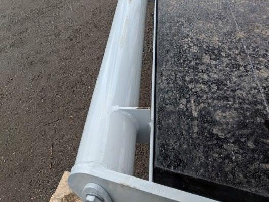
Figure 27: Steel side plate receiving the top and bottom level compressions timber steel hybrid struts.
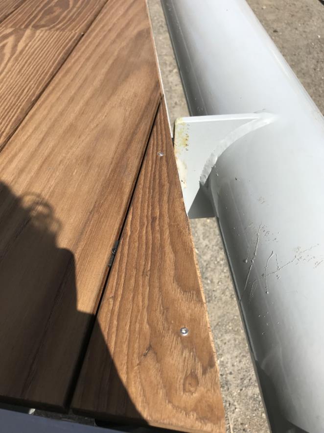
Figure 28: Finish decking adjacency to the connection between timber strut and balcony steel side plate.
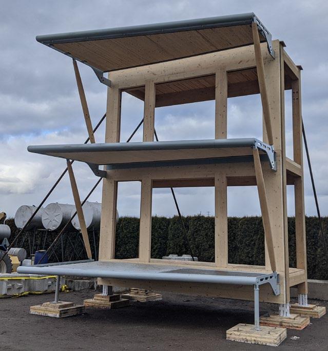
Figure 29: Two-story balcony mock with finish decking put into place. Due to costing and scheduling, the insulation and cladding layers were not included in the mock-up, but the required space to accommodate insulation and cladding was shown.
Figure 30: Showing the perimeter flashing detail where it interfaces with the outside steel structure. The detailing could have been improved to simplify the waterproofing membrane application.
Clockwise from Top: Figure 31: Moisture monitoring sensors were installed underside of DLT/CLT decking to monitor and provide data on wood characteristics over a period of time. A separate report will be issued on performance analysis of the timber decking proprieties and recommendations.
Figure 32: The wood struts have large portions of end grain exposed and facing up. Periodic maintenance through re-coating is required to enhance the timber strut durability.
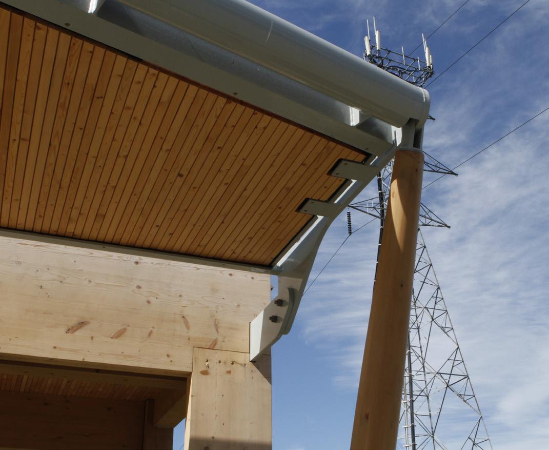
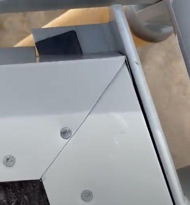
Figure 33: Showing the notches on the underside of the decking for the structural tabs, which requires additional attention in detailing to avoid a potential moisture accumulation and deterioration of timber decking.
As the construction of tall mass timber buildings increase and these structures continue to grow in height, it is necessary to use efficient balcony solutions that are optimized for this building method. Providing robust solutions to the balcony structure and durability in mass timber or tall wood buildings will help position timber as a viable structural alternative to the conventional concrete or steel construction. The balcony mock-up investigated the application of timber as a main structural material with a combination of selective steel members, focusing on the main research objectives. While it is not a comprehensive comparison or examination, the balcony mock-up studied what it means to have a face-mounted timber balcony system to a primary structure consisting of a glulam beam and a column through a unitized CLT wall panel.
Prefabricated from a combination of structural steel members, exposed timber glulam strut, and cross-laminated timber (CLT)/dowel-laminated timber (DLT) decking coupled with a wood decking finish, the balcony system deployed in the site mock-up comes as a modular unit, easing the on-site installation with minimal disruption to the building envelope while reducing the thermal bridging with minimal connection points.
The balcony mock-up research demonstrated the feasibility of delivering a viable thermally broken balcony solution in a mass timber building, in addition to advantages of employing a prefabrication construction approach that streamlines construction scheduling and sequencing and coordination among various consultants and trades.
As we prepare this report, further post-construction monitoring and evaluation of how the timber elements react to various outdoor weather conditions over time are being carried out to holistically assess the durability of this balcony design and construction solution. A report from the post-construction evaluation will be provided once the monitoring process is complete, to provide further update on the following research questions:
1. Understanding the penetration of water through balcony edge details to recognize how the final structure will handle water.
2. Monitoring the performance of different types of decks complete with a durable/translucent finish as needed.
3. Logging moisture characteristics of the balcony timber components via installed moisture monitoring sensors. Additional investigation is required for fire protection. Although it is not installed in this mock-up, sprinklers are required for all EMTC building balconies, even if they are noncombustible, when they are over 610mm in depth based on current BC Building Code and Vancouver Building Bylaw 2019. This is based on a concern with vertical fire spread in EMTC buildings at the exterior. Recent fire demonstrations involving exposed CLT compartments has provided data that supports the potential for a code change to relax balcony sprinkler criteria in EMTC buildings.

Page
Source: City of Vancouver, Bulletin 2016-002-BU, Balcony and Patio Doors in Houses and Dwelling Units, July 7, 2016


00.A1FLASHING
00.A1ENGINEERED
07 52 16.A MODIFIED BITUMINOUS MEMBRANE ROOFING 06 18 00.A1 DLT DECKING REFER TO STRUCTURAL06 10 53.C2 PLYWOOD SHEATHING REFER TO STRUCTURALACCOYA DECKING
PLASTIC PEDESTAL SUPPORTS
ACOUSTIC PROPERTIES
R8._DLT BALCONY DECK TYPEFIRE RATING/ TEST NO
172 PLASTIC PEDESTAL SUPPORTS
102 13 19 38
** CONTRACTOR TO USE HALF SBS AND HALF REINFORCED LIQUID MEMBRANE
ADDITIONAL COMMENTS STC
INSUL THK
DLT -HALF RENIFORCED URETHANE MEMBRANE ACCOYA DECKING R8.A1 07 52 16.A MODIFIED BITUMINOUS MEMBRANE ROOFING
00 00 S43 WOOD STRUCTURAL PANEL, REFER TO STRUCTURAL 1051938
162
ACOUSTIC PROPERTIES
R7._CLT BALCONY DECK TYPEFIRE RATING/ TEST NO
09 81 13 ACOUSTIC PADDING 09 64 00.A1 ENGINEERED WOOD FLOORING
ACCOYA DECKING 255
00 00 S43 WOOD STRUCTURAL PANEL, REFER TO STRUCTURAL CONCRETE TOPPING 17550 14 16
CONTRACTOR TO USE HALF SBS AND HALF REINFORCED LIQUID MEMBRANE
ADDITIONAL COMMENTS STC
INSUL THK
PLY CLT -HALF 2PLY SBS -ACCOYA DECKING R7.A1
ACOUSTIC PROPERTIES
F6._CLT DECK W/ CONCRETE TOPPING TYPEFIRE RATING/ TEST NO
ADDITIONAL COMMENTS STC
INSUL THK
CLT -175V -5 PLY -50mm Topping CONTRACTOR TO COVER CLT AND FLOORING WITH WATER-RESISTIVE MATERIAL TO PROTECT WOOD SURFACE FROM GETTING WET F6.A1
A
5400
A20-00 A20-00 A20-00
E5-A.1 E5-A.1 E5-A.1
LC3575 50
STRUCTURE SLOPE 220mm BALCONY GLULAM POLE STRUT
D1
9 A32-10 A32-10
220mm BALCONY GLULAM POLE STRUT 220mm PIPE AT BALCONY FRONT EDGE MIN. GAP89
W1 W1 MIN.GAP 25
SLIDING DOOR (OPTIWIN MOTURA) 2050
315
E5-A.1 2% C 340 PUNCHED WINDOW (OPTIWIN PURISTA) 1025
315 PUNCHED WINDOW (OPTIWIN PURISTA) 1025 C 160
A32-10
MIN.GAP 89 F/LUMNCO 190
A20-00
A32-104
710
133
A20-00 E5-A.1 A20-00
B 1 2
5400 F/ EXT. CLADDING630 1585 F/T.EXDINGCLAD 680 2025 190
provide Sansin KP 12 UVW coating on all sides. want to keep it looking good https://sansinfactoryfini sh.com/products/under coat-treatment/kp-12/ okay
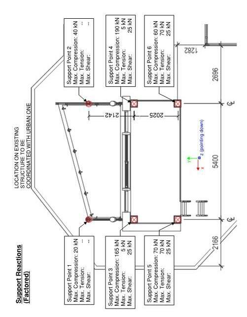
PW Engineer's seal is required.
PW Noted.
PW Noted that all structural Glulam sizes have been reduced.
PW: Noted that all interior floor decking has been changed from CLT to DLT.
please provide a plan for each balcony deck so that sensors can be marked up can you provide assembly schedule to confirm lay up of CLT and DLT, all layers.
PW Given that the balcony mock-up will be exposed to exterior conditions, recommend using KP 12-UVW as a base coat for solar uv and moisture weather protection, with a clear top finish coat to keep wood character/ appearance. Sansin has products available for outdoor timber application.
consider the KP12-UVW
left exposed for long time to keep looking good Will need to onsite confirm adhesion of the reinforced polyurethane deck membrane (BASF, etc) to this coating on the CLT. Can easily be sanded off if not. Presume that the plywood over the DLT will not be coated. Recommend plywood over OSB or ZIP for polyurethane adhesion. SBS base (SOprema Elastophen Flam Stick base layer) should adhere
PIPE 101.6x5.74
OF BASE PLATE
that balcony strut diameter has been further reduced to 165mm from 180mm to keep consistency with balcony edge steel pipe profile.
A53 GR.B
A53
S301
lock blocks at grade for connection of Dayton Superior Tilt-Up Wall Braces against this temporary structure overturning in high wind storm event. At each brace bottom location, connect foot of brace with 6" x 5/8" diameter Hilti Kwik Bolts into one lock block, which is tied side to side against second lock block by industrial nylon cinch straps.
GRID B 1:20
S001
100 mm CLT base pads on compacted gravel ground.


 By: LG


$71.97
$2.09 0.66%
$0.97 0.31%

$3.94
$220.15 69.47%
$12.51 3.95%
$0.00 0.00%
$2.00 0.63%
Structurecraft

Description
Taken Date
2021/01/26 15:33:49
Upload Date
2021/01/27 10:39:26
Uploaded By
Derek Brown
File Name
0BB34569-841F-4C84-AÉ
Location Site daily log
Description
Taken Date
2021/01/26 15:16:23
Upload Date
2021/01/27 10:39:07
Uploaded By
Derek Brown
File Name
D72DD642-DEDA-4412-É
Location Site
Job
Description
Taken Date
2021/01/26 15:04:23
Upload Date
2021/01/27 10:39:06
Uploaded By
Derek Brown
File Name
E552A1FE-C11E-45B9-BÉ
Location Site daily log
Description
Taken Date
2021/01/26 15:04:03
Upload Date
2021/01/27 10:39:05
Uploaded By
Derek Brown
File Name
861995B1-2EB8-4C8B-9É
Location Site
Job
Description
Taken Date
2021/01/26 08:43:26
Upload Date
2021/01/27 10:38:55
Uploaded By
Derek Brown
File Name
3680B013-614A-42AF-B
Location Site daily log
Description
Taken Date
2021/01/25 10:55:31
Upload Date
2021/01/25 14:23:30
Uploaded By
Derek Brown
File Name
C1536D6E-942C-4518-AÉ
Location Site
Job
Description
Taken Date
2021/01/23 15:17:51
Upload Date
2021/01/24 22:19:04
Uploaded By
Derek Brown
File Name
913F7FA2-2DDA-4622-8É
Location Site daily log
Description
Taken Date
2021/01/23 15:17:31
Upload Date
2021/01/24 22:19:02
Uploaded By
Derek Brown
File Name
81A6557C-AF34-44E1-BÉ
Location Site
Job

Description
Taken Date
2021/01/23 11:20:52
Upload Date
2021/01/24 22:19:00
Uploaded By
Derek Brown
File Name
BE40560E-4563-4731-8É
Location Site daily log
Description
Taken Date
2021/01/23 09:19:44
Upload Date
2021/01/24 22:18:57
Uploaded By
Derek Brown
File Name
8D1E302E-D6B9-42D8-É
Location Site
To: Deanna Yue Delta Land Developments Ltd.
From: Elton Gjata / Aik Ablimit
Weather: Cloudy, 6 °C
Date Issued: February 5 , 202 1
Project Name: 8th and Pine NRCAN Balcony
Date of Visit: January 29, 2020 Project Number: 411 629.103
Time
1 1 :00 am
Participants: Kirk Robinson, DELTA Deanna Yue, DELTA James Higgins, RDH Mona Lemoine, PW Aik Ablimit , PW Elton Gjata, PW Ygor Abramskey, Urban One Praise Okougbo , Urban One
ITEM
210129.2
Noted tha t C LT/DLT support wood deck soffit and timber struts did not appear to have finish coating applied. Contractor to provide Sansin KP 12UVW clear finish coating for weather pro tection of timber members Refer to S 100/ Submittal SD00 1 issued Sept. 28 , 2020.

210129.3
ON SITE
Access ladder has not been installed.
I t was discussed on site with the superinte ndent that the access ladder should at least allow full access to level 2 , as per 1/A10 00, 3&6/A20 00 .
210129.4
ON SI TE
Finish decking has not been applied.
To examine appearanc e and performance of the finish decking , it was discussed o n site and subsequently further suggested through e mail communication with De lta and UrbanOne that two different ways of running finish decking boards should be teste d - a) running it parallel at level 1 ; b) placing it perpendicular at level 2 to the building envelope face .
While running the finish boards
ACTION
Urban One
Urban One
Urban One / P&W
ITEM COMMENTS [new items shown
perpendicular to the building face is not recommended as it likely blocks the water flow, P&W will collaborate with contrac tor to confirm potential c ustom support details.
210129.5 When deck finish is installed, contractor to ensure a zero threshold tra nsition (no more than 13mm) from interior to outdoor deck, as per 5/S300 Submittal SD00 1 issued Sept. 28 , 2020 .
2 1 0 1 2 9 .6
ON SITE
Contr actor to provide perimeter balcony waterproofing flashing and topcoat membrane at all sides prior to installation of deck finish, as per 6 &9 /A 32 10.

Contractor to ensure f inish deck clip system to be fastened to the strapping and avo id fasteners penetrat ions into t he membrane.
All parties copied in this report, please notify the author within three working days should any discrepancies be noted.
cc: Kirk Robinson, DELTA Deanna Yue, DELTA James Higgins, RDH Mona Lemoine, PW
Aik Ablimit , PW Elton Gjata, PW Ygor Abramskey, Urban One Praise Okougbo , Urban One
CLIENT Perkins&Will
VISIT DATE January 29th, 2021
WRITER James Higgins
TO Elton Gjata (PW)
PROJECT R 11605.001 Pineview NRCan Research
REVIEWER Graham Finch
CC Mona Lemoine, Alysia Baldwin (PW) DATE February 16th, 2021
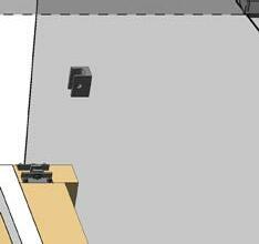
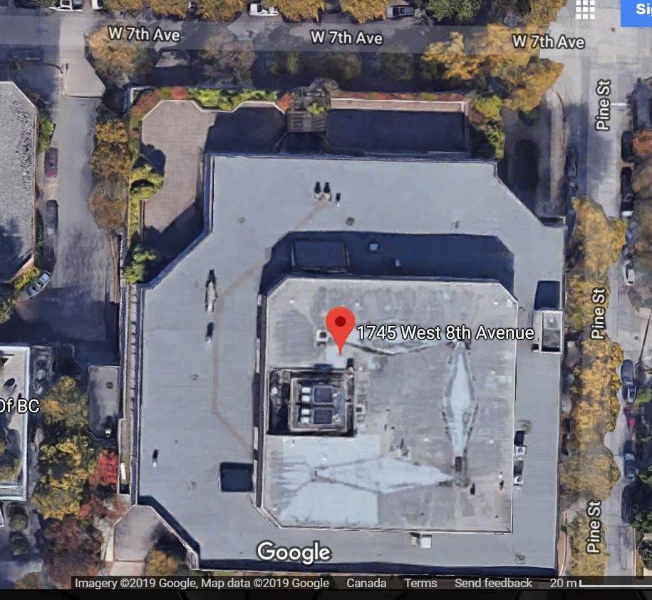
REGARDING Site Visit 01: Balcony Mockup at 21551 Westminster Hwy, Richmond
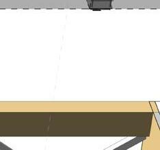
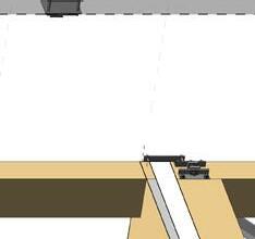
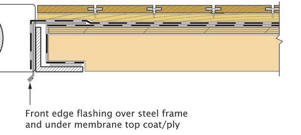
First ply/coating of the SBS/urethane membrane has been installed on the top surface and sides and portions of the underside at the perimeter. The remaining components to be installed include the perimeter flashing, second ply/coating of waterproofing, and the door threshold transition components. Flashing to be installed within the steel frame on the balcony side edge and over the steel angle on the front edge. The sketches below show the general arrangement
Action Required: PW/U1 to confirm detail and U1 to install remaining components.
The deck planking will run parallel and perpendicular to the balcony/facade direction on different levels. Planking support pieces (strapping) must be arranged to avoid blocking drainage from the waterproofing surfaces per sketches below. Decking must not fasten into balcony waterproofing. Potential structural/lifting restraint of the decking from the top side to be confirmed if needed per structural.
Action Required: PW/U1 to confirm decking support arrangement.
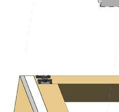
Each balcony includes coated steel framing and through wall connectors back to the structure, which support the CLT and DLT balcony panels. The wood balcony installation sequence appears to require a three step process as follows:
1. Position the wood balcony on temporary sawhorses/stands above the steel support frame to allow installation of the first ply/coating of the waterproofing membrane on the top and perimeter of the wood.
2. Lift the support frame up to the wood balcony structure and fasten in place. If possible, other balcony waterproofing/finish items can be completed except at door threshold/building side tie ins. These may include portions of walking surfaces, underside finishes, and guardrails.
3. Lift the steel structure/wood balcony as one piece and attach to the connections on the façade. Complete remaining structural/waterproofing/finishing as needed.
The façade connectors include hook bracket/bolt components to allow the connector to be lowered into place and supported without additional fasteners. The brackets currently do not include the built in adjustability that may be needed to position the brackets, but the general installation sequence appears to be represented. A cap bolt is installed on the top side of the hook brackets to prevent lift.
As per the attached sensor plan, RDH will be installing moisture monitoring equipment on the mockup once waterproofing and decking is complete, and site access is in place
Moisture pins will be left in place to log the moisture characteristics of the balcony wood components.
Action Required: PW/U1 to confirm access to upper balconies is in place.
Yours truly, James Higgins | AScT Associate, Building Science Technologist jhiggins@rdh.com
T 604 873 1181 x153
RDH Building Science Inc.
encl: Monitoring sensor plan (pdf markup)
Graham Finch | Dipl.T, MASc, P.Eng Principal, Senior Building Science gfinch@rdh.com
To: Deanna Yue Delta Land Developments Ltd.
From: Mona Lemoine / Elton Gjata / Aik Ablimit
Weather: Cloudy, 11
Date of Visit: March 16 , 202
Date Issued: March 30 , 202 1
Project Name: 8th and Pine NRCAN Balcony
Project Number: 411 629.103
Participants: James Higgins, RDH Diana Guo, PW Elton Gjata, PW Ricardo Dupouy, Urban One Miguel Zapiola, Urban One
CC: Alysia
Mona Lemoine, Aik
ITEM COMMENTS [new items shown
210129.2
Noted that CLT/DLT support wood deck soffit and timber struts did not appear to have finish coating applied
Contractor to provide Sansin KP12 UVW clear finish coating for weather protection of timber members. Refer to S100/ Submittal SD00 1 issued Sept. 28 , 2020.
210129.3
ON SITE
Access ladder has not been installed.
I t was discussed on site with the superintendent that the access ladder should at least allow full access to level 2 , as per 1/A10 00, 3&6/A20 00 .
210129.4
ON SITE
Finish decking has not been applied.
To examine appearance and performance of the finish decking, it was discussed on site and subsequently further suggested through e mail communication with Delta and UrbanOne that two different ways of running finish decking boards should be tested - a) running it parallel at level 1 ; b) placing it perpendicular at level 2 to the building envelope face
While running the finish boards
Urban One / P&W
ITEM COMMENTS [new items shown in bold text, old items shown in regular text.]
perpendicular to the building face is not recommended as it likely blocks the wate r flow, P&W will collaborate with contractor to confirm potential custom support details.
210129.5 When deck finish is installed, contractor to ensure a zero threshold transition (no more than 13mm) from interior to outdoor deck, as per 5/S300 Submittal SD001 issued Sept. 28, 2020.
2 1 0 1 2 9 .6
ON SITE
Contractor to provide perimeter balcony waterproofing flashing and topcoat membrane at all sides prior to installation of deck finish, as per 6 &9 /A32 10.
Contractor to ensure finish deck clip system to be fastened to the strapping and avoid fasteners penetrat ions into the membrane.
UrbanO
Urban
210 316.7
ON
Perimeter flashing has been installed at Level 3 for review. Refer to RDH Site Visit 02 Report for corrections required at all levels.

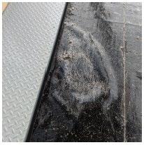
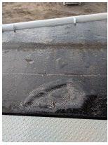
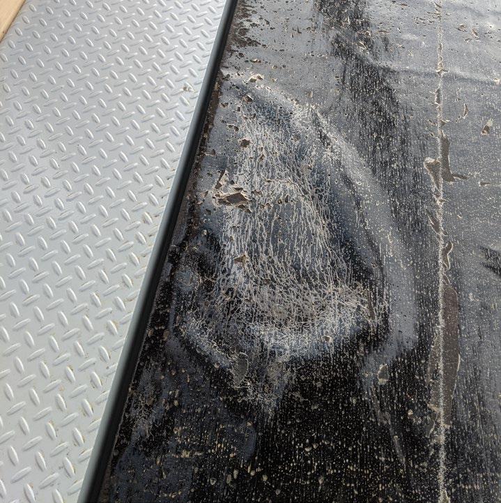
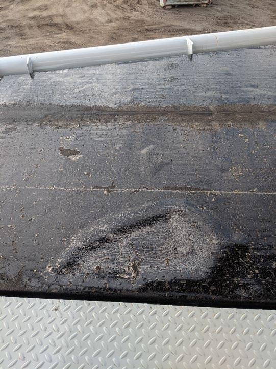
210316.8 Note blistering spots on Level 1 SBS membrane Refer to RDH Site Visit 02 Report for action required.
All
cc: Kirk Robinson, DELTA Deanna Yue, DELTA James Higgins, RDH
Urban One
days
Urban One
discrepancies
noted.
Mona Lemoine, PW
Aik Ablimit , PW
Elton Gjata, PW
Ricardo Dupouy, Urban One Miguel Zapiola, Urban One Brent Olund, Urban One
CLIENT Perkins&Will
VISIT DATE March 16th, 2021
WRITER James Higgins
TO Elton Gjata (PW)
PROJECT R 11605.001 Pineview NRCan Research
REVIEWER Graham Finch
CC Mona Lemoine, Alysia Baldwin (PW) DATE March 30th, 2021 (update)
REGARDING Site Visit 02 Update: Balcony Mockup at 21551 Westminster Hwy, Richmond
The perimeter flashing has been installed at Level 3. Several items require correction for the Level 1 and Level 2 install as follows:
1. The vertical leg of the flashing at the front edge is slotted between the panel edge and the L angle structure which is incorrect. It should extend over the exterior side of the L angle to allow water shedding (see below)
2. The flashing is installed with nails into the deck. It should instead be set into sealant or temporarily taped in place to avoid penetrations into the bottom membrane.

3. The side edge flashing should include a drip edge over the structural tab (see below)
1. PW/U1 to confirm detail and U1 to install remaining components. Avoid penetrations into bottom membrane ply.
2. U1 to leave Level 3 flashing as is and install remaining membrane/components
PW noted blistering spots beneath the Level 1 SBS membrane It could not be confirmed if these are the result of membrane discontinuities.
U1 to cut open blisters to confirm if water is present, drain and dry wood surface if necessary, repair as necessary prior to second ply installation.
Yours truly, James Higgins | AScT Associate, Building Science Technologist jhiggins@rdh.com
T 604 873 1181 x153
RDH Building Science Inc.
Graham Finch | Dipl.T, MASc, P.Eng Principal, Senior Building Science gfinch@rdh.com
CLIENT Perkins&Will
VISIT DATE June 3rd, 2021
WRITER James Higgins
Elton Gjata (PW)
PROJECT R 11605.001 Pineview NRCan Research
REVIEWER Graham Finch
Mona Lemoine, Aik Ablimit (PW) DATE June 28th, 2021
REGARDING Site Visit 03: Balcony Mockup at 21551 Westminster Hwy, Richmond

RDH was on site on 2021 05 13 and 2021 06 03 to view the balcony finish components including the decking and wood coating. All items noted in our Site Visit 03 Notes report appear to have
for the purpose of this balcony mockup This visit serves as the last review for this phase of the mockup work Sensor monitoring of the wood moisture content
continue for the foreseeable future
Action Required:
Graham Finch | Dipl.T, MASc, P.Eng Principal, Senior Building Science gfinch@rdh.com
To: Deanna Yue Delta Land Developments Ltd.
From: Mona Lemoine / Aik Ablimit Date Issued: July 1 2 , 2021
Weather: Sunny, 22 °C
ON
Project Name: 8th and Pine NRCAN Balcony
Date of Visit: June 3, 2021 Project Number: 411629.103
Time of Visit: 3 :30 pm 4:30 pm
Participants: Deanna Yue, Delta James Higgins, RDH Mona Lemoine, PW Aik Abilimit, PW Elton Gjata, PW Alysia Baldwin, PW Tom Bruvold, Urban One Brent Olund, Urban One
CC:
Overall
All items noted in RDH’s last Site Visit 03 Notes report and Perkins&Will Site Visit 02 report appear to have been addressed adequately for the purpose of this balcony mockup. This site visit serves as the last review for this phase of the mockup work. RDH will continue with sensor monitoring of the balcony timber deck moisture content for the foreseeable future.
All parties copied in this report, please notify the author within three working days should any discrepancies be noted.
cc:
Kirk Robinson, DELTA
Deanna Yue, DELTA
James Higgins, RDH
Mona Lemoine, PW
Aik Ablimit, PW
Elton Gjata, PW
Tom Burvold, Urban One
Ricardo Dupouy, Urban One
Miguel Zapiola, Urban One Brent Olund, Urban One
Upper
604


be
are tangential
Upper Canada
Products 5768 Trapp Ave, Burnaby 604 374 5435

Accoya recommends that a minimum of 25mm of fastener penetration be obtained for deck installations. If Accoya is used as a subframe, they suggest a minimum of 10mm between the end of the fastener and the bottom of the sub assembly board. This creates a 35 mm minimum total sub assembly height from a fastening perspective.
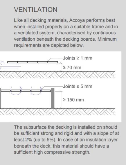

For typical deck applications Accoya’s technical literature recommends a 70mm ventilation space. There may be an argument that the deck system’s exposure to wind/air flow should allow for better ventilation in comparison to a traditional ground level deck. The mock up testing should provide helpful data regarding moisture build up. Check for mold or mildew growth at the edges of the decking material.
Upper Canada Forest Products 5768 Trapp Ave, Burnaby 604 374 5435

On the parallel deck design considerations should be made to ensure the secure fastening of the shortest angled deck board. In this orientation an additional sub frame support may be required.
Thermal Ash Parallel Deck:
• Additional Accoya resources have been attached in the accompanying email.
• For additional information on Thermal Ash questions can be addressed by Thermalwood Canada product experts. Please reach out to Matthew Wollin mwollin@ucfp.com as questions arise and UCFP can facilitate further product investigations.
• Final design and substructure should be reviewed by a deck installation expert
Upper Canada Forest Products 5768 Trapp Ave, Burnaby 604 374 5435
1220 Homer Street
Vancouver, British Columbia V6B 2Y5


