Project Cost Estimation
Course Number
BLDG 6851
Professor: Dr. Po-Han Chen
Group 11
Final report
Preetam Ola (40233353)
Winter 2023

1. Introduction
Cost estimation is the process of estimating the amount of money and other resources required to finish a project within a specific time frame. Cost estimation generates a total sum that establishes a project's budget by taking into account all project-related requirements, including labor and supplies. An early cost estimate can help an organization decide whether to approve a project, and if the project proceeds, it can help define its scope. A company may decide to scale back the project to match what they can afford if the cost estimation is too high (it is also required to begin securing funding for the project). The cost estimate is used to control all associated costs once the project is underway in order to keep it under budget. Should the cost estimation be over the budget, the owner’s specifications must be altered in accordance with the target budget.
2. Objective
This report aims to calculate detailed estimation for a prospective two-story building to be constructed in Toronto. For its cost estimation to report to the owners, we have considered these steps:
✓ Quantity Take-off (QTO)
✓ Pricing
✓ Master Format conversion
✓ Detailed estimation
3.
Project Description
A two-story residential building to be constructed in Toronto, Ontario in 2023 with a Gross Floor Area of roughly 5,500 Square Feet is a significant undertaking that requires careful planning and attention to detail. The preliminary design, which includes a basement, a ground floor, and a second floor, suggests that the building will have ample space for living, entertaining, and storage. The conceptual structural framework is envisioned as being made of steel. Steel's high strength-to-weight ratio and versatility make it an ideal material for use in conceptual structural frameworks. It can support heavy loads without adding unnecessary weight to the structure, and it can be easily fabricated into various shapes and sizes to suit the needs of a particular design. Steel is also resistant to fire and pests, making it a
safe choice for buildings that require high levels of protection. Moreover, steel is an environmentally friendly material, as it can be recycled and repurposed after its initial use, reducing waste and minimizing the environmental impact of construction projects.
The exterior finishes for the building will be covered by masonry bricks. Masonry is a durable and long-lasting building material, that provides great insulation and fire resistance. It also adds an aesthetic appeal to the building, creating a classic and timeless look. Masonry bricks come in a wide range of varieties, each with its own unique characteristics, colors, and textures. The choice of masonry brick will depend on the design aesthetic, budget, and other factors.
4. Detailed Estimation
In order to do the detailed estimation, the following steps should be undertaken:
• Work Breakdown Structure (WBS) use (Uni Format approach)
• Quantity Take-Off (QTO)
• Pricing
4.1.
Work Breakdown Structure (WBS)
Utilizing the work breakdown structure (WBS), which is a project management tool, helps large projects to be completed step-by-step. The WBS allows integrating the scope, cost, and deliverables into a single tool by dividing the project into smaller components. Albeit most WBSs are deliverable-based (Master Format), they can also be phase-based (Uni Format).
A Substructure B Shell
A10 Foundations
A1010 Standard Foundation
A1020 Special Foundations
A1030 Slab-on-Grade
A20 Basement Construction
A2010 Basement Excavation
A2020 Basement Walls
C Interior
C10 Interior Construction
C1011 Partitions
C1020 Intr. Doors
C1030 Fittings
C20 Stairs
C2010 Stair Construction
C2020 Stair Finishes
C30 Interior Finishes
C3010 Wall Finishes
C3020 Floor Finishes
C3030 Ceiling Finishes
B10 Superstructure
B1010 Floor Construction
B1020 Roof Construction
B20 Exterior Exclosure
B2010 Exterior Walls
B2020 Ext. Windows
B2030 Ext. Doors
B30 Roofing
B3010 Roof Covering
B3020 Roof Openings
D Services
D10 Conveying
D1010 Elevators & Lifts
D20 Plumbing
D2010 Plumbing Fixtures
D2020 Domestic Water Distribution
E Equipment & Furnishings
E10 Equipment
E1030 Vehicular Equipment
E1090 Other Equipment
E20 Furnishings
E2010 Fixed Furnishings
D2030 Sanitary Waste Z General
D2040 Rain Water Drainage
D30 HVAC
D3010 Energy Supply
D3020 Heat Generating Systems
D3030 Cooling Generating Systems
D3040 Distribution Systems
D3050 Terminal & Package Units
D3060 Controls and Instrumentation
D3070 Systems Testing & Balancing
D40 Fire Protection
D4010 Sprinklers
D4020 Standpipes
D50 Electrical
D5010 Electrical Service & Distribution
D5020 Lighting & Branch Wiring
D5030 Communication & Security
D5090 Other Electrical Systems
4.2. Quantity Take-Off (QTO)
Z20 Contingencies
Z2010 Design Contingency
Z2020 Escalation Contingency
Z2030 Construction Contingency
The Quantity Take-Off process is crucial in construction cost estimation, involving the measurement of labor, materials, and resources from project drawings. This data is then used to prepare a detailed cost estimate, providing a comprehensive overview of total project expenses.
4.3.
Pricing
Pricing in construction cost estimation is a critical process that involves calculating all costs associated with a project, including materials, labor, equipment, and other expenses. By breaking the project into components such as excavation, foundation, framing, roofing, electrical, plumbing, and finishing work we can estimate costs more accurately. Utilizing RSMeans provides a comprehensive list of unit prices that account for overhead and profit. Factors like project location, design complexity, and material quality significantly influence these estimates. This approach ensures a comprehensive budget, covering both direct and indirect costs, and helps manage expenses effectively, facilitating timely completion of the project within budget constraints.
Excavation (Cut)
Quantity: 9507.8 Cu.ft
Unit Price: 6.88
Total cost of Cut: 9507.8 × 6.88 = 65,409.65
Concrete (Slab)
Quantity: 534.2 Cu.ft
Unit Price: 137.34
Total cost of Cut: 534.2 × 137.34 = 73,371.15
Woodwork (Sill Plate)
Quantity: 363.3 BF
Masonry (Bricks)
Quantity: 12892 No. Unit Price: 363.3 Unit Price: 3.31
Total cost of Cut: 363.3 × 363.3 = 5,543.91 Total cost of Cut: 12892 × 3.31 = 42,640.30
5.
Quantity Take-Off (QTO) Calculation
Metals
There are steel columns and steel lintels in this project. For the location and the information, please refer to Appendix.
Woods:
The wood section divided into Walls, Floors, and roofs. For more detailed calculations please refer to Appendix.
Sample Calculation for Basement Walls:
Wooden walls above the retaining walls and wooden interior walls are calculated.
Bottom Plates:
We used 1.55E Timber Strand® LSL 1 ½” × 5½" (2” ×6”)


Figure 1: Timber Strand, Microlam, and Parallel Beams, Headers, and Columns - Pacific Northwest Specifier's Guide
Total length: 100.94’
Total BFM:
100.94 BF
Top Plates:
We used 1.55E Timber Strand® LSL 1 ½” × 5½" (2” ×6”)
Total length with doubling parts: 138.57’
Total BFM:
138.57 BF
Wall Stud:
Use 1.55E Timber Strand® LSL 1 ½” × 5½" (2” ×6”)
There are different heights for wall studs.
Total Length of all: (11’x55) +(74x9.515’) +(11x5.71’) +(5.71’x27) +(6.2’x34) +(7.45’x25)
+(6.2’x17) = 2028.54’
Total BFM:
2028.54 BF
Blocking:
Use 1.55E Timber Strand® LSL 1 ½” × 5½" (2” ×6”)
Total Length of all: 88.108
Total BFM: 88.108 BF
Hold Downs:
HDB/HD is used for controlling lateral load in shear walls.

Total Number: Walls Sheathing:
6 HDB/HD
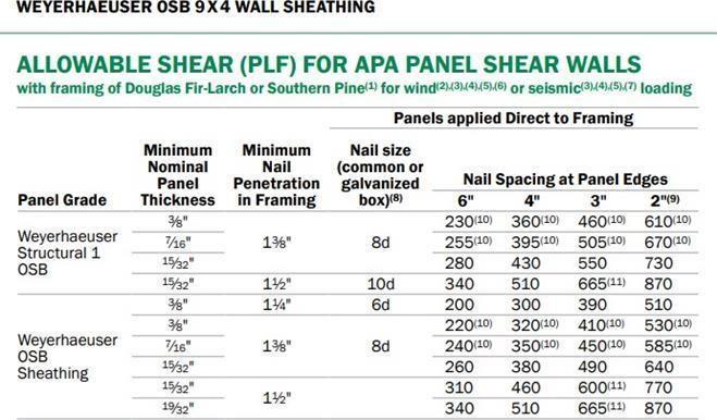
Use 9’x4’,7/16”


(25.75x7.45) +(17.5x6.2) +(40.21x6.2) +(6.2x15.125) +(5.71x28.125) +(12.83x5.71)
+(9.515x30.618) +(19.86x11) +(16.8x9.515) +(20.83x11) = 1776.04 SF
1 sheath of OSB 9x4 = 15.75 BF
Total:
50 sheaths
787.5 BF
Sample Calculation for Floors:
Basement Framing Plan (Main Floor Joists):

BF/ft
Number:
5.92’/1’ + 1 = 7 Pieces
Length: 16.25’ Each
bf/ft

Sample Calculation for Roofs:
Roof Rafters:
Common Rafters: (3:12) / 2” × 8” SPF@ 16”

NominalThickness:8”=>Actualthickness= 7.25”NominalWidth:2”=>Actualwidth= 1.5”
Rise:
Rise=3.095’

Roofs
Roof Rafters:
Common Rafters: (3:12) / 2” × 8” SPF@ 16”

NominalThickness:8”=>Actualthickness=7.25”
NominalWidth:2”=>Actualwidth=1.5” Rise:
3.095’
AdditionalLength=0.151’
TotalLength: 12.77’+0.151’
Total Length = 12.92’
NumberofRafters:
Total No. = 52
FBM=
Common Rafters: (12:22) / 2” × 6” SPF@ 16”

NominalThickness:6”=>Actualthickness=5.5”
NominalWidth:2”=>Actualwidth=1.5” Rise:
=3.98’
AdditionalLength=0.25’
TotalLength: 4.54’+0.25’
Total Length = 4.79’
Number of Rafters: 1:
����������ℎ 12 = 5.5"/12 22
Total No. = 119
TotalFBM=
1.((8.09′ ×1)/16”)+1=8
2.((2.63′ ×12)/16”)+1=3
3.((8.75′ ×12)/16"+1=8
4.((5′×12)/16")+1=5
5.((0.71′ ×12)/16")+1=2
6.((39.92′ ×12)/16")+1=31
7.((39.92′ ×12)/16")+1=31
8.((39.92′ ×12)/16")+1=31
119×4.79′×2"×6" = ������.�������� 12"

HipRafters:(3:12)/3-2”×10”SPF
NominalThickness:10”=>Actualthickness=9.25”
NominalWidth:2”=>Actualwidth=1.5”
Rise:(Same as common rafters)
Rise=3.095’
RunLength:
17.51’ HipRafterLength:

AdditionalLength:
AdditionalLength=0.136’
TotalLength:
17.79’+0.136’
Total Length = 17.93’
NumberofHipRafters:
No.=4
Hip Rafters: (12:22) / 3 - 2” × 8” SPF
NominalThickness:8”=>Actualthickness=7.25”
NominalWidth:2”=>Actualwidth=1.5”
Rise:(Sameascommonrafters)
Rise=3.98’
RunLength:
Length=3.07’
HipRafterLength:

AdditionalLength:
AdditionalLength=0.783’
TotalLength:
5.03+0.783’
Total Length = 5.813’
Number of Hip Rafters: No.= 4
TotalFBM=
4×3×5.813′×2"×8" = ����.�������� 12"
JackRafters:(3:12)/2”×8”SPF@NominalThickness:8”=>Actualthickness=7.25”

NominalWidth:2”=>Actualwidth=1.5”
Number of Jack Rafters: Number of Sides = 8 ;8×9=72 Jack Rafters with different lengths.


Length=11.4’
AdditionalLength:
AdditionalLength=0.151’ TotalLength: 11.4’+0.151’
Length 1: 11.551’
2: Run:
11.05-1.33=9.72’
AdditionalLength=0.151’ TotalLength: 10.02’+0.151’ Total Length 2: 10.171’
3: Run:
9.72-1.33=8.39’
4: Run:
8.39-1.33=7.06’
Length=7.28’
AdditionalLength:
AdditionalLength=0.151’
TotalLength:
7.28’+0.151’
Total Length 4: 7.431’
5: Run:
7.06-1.33=5.73’
Length=5.906’
AdditionalLength:
AdditionalLength=0.151’
TotalLength:
5.906’+0.151’
Total Length 5: 6.057’
6: Run:
5.73-1.33=4.4’
7: Run:
4.4-1.33=3.07’
Length=3.165’
AdditionalLength:
AdditionalLength=0.151’
TotalLength:
3.165’+0.151’
Total Length 7: 3.316’
8: Run:
3.07-1.33=1.74’
Length=1.794’
AdditionalLength:
AdditionalLength=0.151’
TotalLength:
1.794’+0.151’
Total Length 8: 1.945’
9: Run:
1.74-1.33=0.41’
0.43’+0.151’
Total Length 9: 0.581’
Total Length= 54.544’ for one side
TotalFBM=
Jack Rafters: (12:22) / 3 - 2” × 6” SPF @ 16”

NominalThickness:6”=>Actualthickness=5.5”
NominalWidth:2”=>Actualwidth=1.5”
NumberofJackRafters:
Number of Sides = 8
8×1=8 Jack Rafters same size

Run:10”
Rise:
(rise/10) =(12/22)
Rise= 5.455”
Length: √5.4552 +102= 11.391”; Length= 11.391”
Additional Length:( ����������ℎ/5.5”) =12/22
Additional Length = 3”
Total Length:
11.391” +3” =14.391” =1.2’
Total Length: 1.2’
Total Length= 1.2’ for one side
Total FBM= (8 × 1.2′ × 2" × 6")/12"=�� ������
Roof Joists: 2” ×6” SPF
Roof Sheathing:202.19 BF
From the roof plan,
Total Roof Area: 1971.46 SF
Each Sheath:(4’×8’×3/4”) = 32 SF
Number of Sheaths: 1971.46/32=62 Sheaths;976.5 BF; OSB (9’×4’×7/16”
Girder and Lintels:
Basement Floor:
of Girders

Posts:
Second Floor and Roof Framing Plan:
For posts between second floor framing plan and roof framing plan 4 P3 and 2 P5 columns are usedsince the drawings are not accurate and it has mistaken. It couldn’t be any columns in perimeter of house in this level regard to section 1 and 2 Posts: 90.42’


Framing Cap/Base: BC8 Cap/Base Cap:
BC8 Base: 28 BC8
Total of Base/Cap:

Figure 8: Figure 15 Catalog: Wood Construction Connectors Canadian Limit States Design 2018-2019 (C-C-CAN2018)
Sill Plate:
Use 1.55E Timber Strand® LSL 1¾" × 9½" (2” ×10”) over concrete surfaces.
Total Length: 218’
Total BFM:


Steel Lintel Main floor:
Wood Works:
Steel Lintels:Second floor:
Steel Lintel Basement:
Wall Stud 22 1.55E TimberStrand® LSL 1 ½” × 5½" (2” ×6”)
Blocking

Floor Joist
Floor:
Basement Framing Plan (Main Floor Joists):Floor Joist:
1:9 ½” TJI S47 @ 12”
Number:5.92’/1’ + 1 = 7 Pieces; Length:16.25’ Each
2:1 ¾” × 9 ¼” LVL / Assume @ 12’
Number:11.17’/1’ +1 = 13 Pieces1; Length:20.25’ Each
3:9 ½” TJI S47 @ 12”
Number:23.34’/1’ +1 = 25 PiecesLength:16.25’ Each
4:9 ½” TJI S47 @ 16”
Number:29.25’×12/16” +1 = 24 Pieces; Length:10.125’ Each
5:9 ½” TJI S47 @ 16”
Number:2.3’×12/16” +1 = 3 Pieces; Length:6.21’ Each
6:9 ½” TJI S47 @ 16”
Number:4.09’×12/16” +1 = 5 Pieces; Length:16.875’ Each
7:9 ½” TJI S47 @ 16”
Number:10.375’×12/16” +1 = 9 Pieces; Length:17.875’ Each
8:9 ½” TJI S47 @ 16”
Number:13.84’×12/16” +1 = 12 Pieces; Length:16.875’ Each
9:9 ½” TJI S47 @ 16”
Number:8.625’×12/16” +1 = 8 Pieces;17.875’ Each
10:9 ½” TJI S47 @ 16”
Number:3.34’×12/16” +1 = 4 Pieces; Length:16.875’ Each
Openings:
Trimmers are not doubled since there are beams over openings. Only for the west side of the opening rim will be put.
Rim Joist:
Regard to “Specifier's Guide for TJI s31, s33 and s47 Joists for East Canada” TJI S47 is used as a rim joist.

North and South:
Length:
2× (5.92+11.17.23.34) = 80.86’
Blockings:
Regard to “Specifier's Guide for TJI s31, s33 and s47 Joists for East Canada” TJI S47 is used as a blocking joist. for over 8’ long floor.

12: Specifier's Guide for TJI s31, s33 and s47 Joists for East Canada
1,2,3 (16.25’):
Put 4 rows of blocking panels (near wall, 2 mid-points and near beam) 16.25/8 +1 =4
Top Row:5.92+23.34+11.17 = 29.26’
Mid-Point 1,2:2(5.92+11.17+23.34) = 80.86’
Bottom Row:5.92+11.17+23.34= 40.43’
Length:29.26+40.43+40.43 = 161.72’
6,7,8,9: Same 4 rows Total length:2(162.72) = 323.44’ of blockings
Double joist for bearing walls.
*All connections are by nail.
In basement framing plan there are different elevations which constructed by knee walls, so
1: Floor Joist: 2” × 6” SPF @ 16”
Number:8.71’×12/16” + 1 = 8 Pieces
Length:4.17’ Each
Rim Joist: 2” × 6” SPF
Number:2 Pieces
Length:8.71’ Each
2: Floor Joist: 2” × 8” SPF @ 16”
Number:6’×12/16” + 1 = 6 Pieces
Length:5’ Each
Rim Joist: 2” × 8” SPF
Number: 2 Pieces
Length: 6’ Each Landing:

Floor Joist: 2” × 6” SPF @ 16”
Number:9.58’×12/16” + 1 = 9 Pieces
Length:3.67’ Each
Rim Joist: 2” × 6” SPF; Number:2 Pieces
Length: 9.58’ Each 9 ½” TJI S47
Total Length:1854.305’;2061.95 BF
1 ¾” × 9 ¼” LVL
Total Length:263.25’;438.75 BF; 2” × 6” SPF
Total Length:102.97’=102.97 BF 2” × 8” SPF; Total Length=42’56 BF

Main Floor Framing Plan (Second Floor Joists):
Floor Joist:

1:9 ½” TJI S47 @ 16”
Number:6.75’×12/16” +1 = 7 Pieces; Length:18.3’ Each
2:9 ½” TJI S47 @ 16”
Number:9.5’×12/16” +1 = 9 Pieces; Length:22.3’ Each
3:9 ½” TJI S47 @ 16”
Number:24’×12/16” +1 = 19 Pieces; Length:18.3’ Each
4:9 ½” TJI S31 @ 16”

Number:27.25’×12/16” +1 = 22 Pieces; Length:9.92’ Each
6:9 ½” TJI S47 @ 16”
Number:4.09’×12/16” +1 = 5 Pieces; Length:17’ Each
7:9 ½” TJI S47 @ 16”
Number:10.42’×12/16” +1 = 9 Pieces; Length:18’ Each
8:9 ½” TJI S47 @ 16”
Number:13.84’×12/16” +1 = 12 Pieces; Length:17’ Each
9:9 ½” TJI S47 @ 16”
Number:8.59’×12/16” +1 = 8 Pieces; Length:18’ Each
10:9 ½” TJI S47 @ 16”
Number:3.3’×12/16” +1 = 4 Pieces; Length:17’ Each
11:9 ½” TJI S47 @ 16”
Number:3.8’×12/16” +1 = 4 Pieces; Length:1’ Each
Openings: TJI S47:1+2(3.8) = 8.6’
Rim Joist: TJI S47 North and South:2(40.25) = 80.5’
Block: TJI S47 1,2,3
Number of Rows:18.3/8+1 = 4 Rows
Length:4(40.25) = 161’
6,7,8,9
Number of Rows:17/8+1 = 4 Rows Length:4(40.25) = 161’
Total Length of Blocking Panels:322’
Landing and Powder Room:(Main floor)

Floor Joist: 2” × 6” SPF @ 16”
Number:6.7’×12/16” + 1 = 7 Pieces; Length:3.5’ Each; Rim Joist: 2” × 6” SPF
Number:2 Pieces
Length: 6.7’ Each; Floor Joist: 2” × 6” SPF @ 16”
Number: 3.5’×12/16” + 1 = 4 Pieces; Length:3.5’ Each; Rim Joist: 2” × 6” SPF
Number:2 Pieces
Length: 3.5’ Each.
Floor Joist: 2” × 6” SPF @ 16” (Powder Room)
Number:8.375’×12/16” + 1 = 8 Pieces
Length:3.5’ Each; Rim Joist: 2” × 6” SPF
Number:2 Pieces Length:8.375’ Each
9 ½” TJI S47; Total Length:1754.6’; 1951.08 BF
9 ½” TJI S31; Total Length:218.24’;180.73 BF 2” × 6” SPF
Total Length:103.65’=103.65 BF
Second Floor Framing Plan (Ceiling Joists):
Ceiling Joist and Rim Joist:


a: Ceiling Joist: 2” × 8” SPF @ 16”; Number:38.63’×12/16” + 1 = 30 Pieces
Length:15.29’ Each; Rim Joist: 2” × 8” SPF
Number:1 Piece; Length:38.63’
1: Ceiling Joist: 2” × 8” SPF @ 16”
Number: 15.1’×12/16” + 1 = 13 Pieces; Length:12.88’ Each
2: Ceiling Joist: 2” × 8” SPF @ 16”
Number:17.34’×12/16” + 1 = 15 Pieces; Length:12.88’ Each
3: Ceiling Joist: 2” × 8” SPF @ 16”
Number:6.21’×12/16” + 1 = 4 Pieces; Length:6.5’ Each
b: Ceiling Joist: 2” × 8” SPF @ 16”
Number:38.63’×12/16” + 1 = 30 Pieces; Length:15.67’ Each
Rim Joist: 2” × 8” SP
Number: 6.21’×12/16” + 1 = 4 Pieces
Length: 6.5’ Each b: Ceiling Joist: 2” × 8” SPF @ 16”
Number: 38.63’×12/16” + 1 = 30 Pieces
Length: 15.67’ Each, Rim Joist: 2” × 8” SPF
Number:
1. Piece Length:38.63’ Block: 2” × 8” SPF
a: Number: 15.29/8+1= 3 rows Length:38.63’
1: Number: 12.88/8+1= 3 rows Length: 15.1’
2: Number: 12.88/8+1= 3 rows Length: 17.34’
b: Number: 15.67/8+1= 3 rows Length: 38.63’
Double under bearing wall: 15.29+15.29+6.5+15.67= 52.75’.
Subfloor Sheathing
8 ft. long, 4 ft. height and ¾ in. thickness Weyerhaeuser Edge™ oriented strand board (OSB) floor panels is used for subfloor sheathing and the longest direction is Appendix.

Basement Finished Plan:75 sheaths
Basement Framing Plan:(Main Floor)
Number of Columns: (1,2,3) 16.25/4= 5 columns Number of Rows:
40.25/8= 6 rows Sum:5×6= 30 sheaths
Number of Columns: (4) 10.125/4= 3 columns Number of Rows:
30.125/8= 4 rows Sum:4×3= 12 sheaths
Number of Columns: (6,7,8,9,10) 16.88/4= 5 columns
Number of Rows:40.25/8= 6 rows Sum:5×6= 30 sheaths
Additional Parts: (2,3’,5,6’,7,9)
2+1+1+1+2= 7 sheaths Sum:79 Sheath
Main Floor Framing Plan: (Second Floor)
Number of Columns: (1,2,3) 18.3/4= 5 columns
Number of Rows: 40.25/8= 6 rows Sum:5×6= 30 sheaths
Number of Columns: (4) 9.92/4= 3 columns Number of Rows: 27.25/8= 4 rows
Sum:4×3= 12 sheaths
Number of Columns: (6,7,8,9,10) 17/4= 5 columns
Number of Rows: 40.25/8= 6 rows Sum:5×6= 30 sheaths
Additional Parts: (2,3’,11,6’,7,9)
2+1+1+1+2= 7
sheaths Sum:79 Sheaths Total:
233 Sheaths=5592 BF
4’×8’×3/4” OSB=Each Sheath is 24 BF
For this section, the sequence of activities was first converted from Uni Format to Master Format, which resulted in a list of activities with their corresponding Master Format code. These activities were then categorized into 5 different categories, which correspond to various phases or aspects of the project.
To calculate the project's cost, we used a one-month trial version of RSMeans. However, the trial version only provided access to the Master Format 2018 and cost data from 2011. Therefore, the cost data from 2011 had to be converted to 2023 to fathom how much it would cost were it to be built in 2023.

Hence, the complete cost estimation for constructing this project in 2023 is just over 1.26 million Canadian Dollars.
8. Conclusion
He estimated project cost in 2011 was $805,000. Adjusted for inflation using the Historical Cost Index from RS Means, the 2023 estimate rises to approximately $1.26 million. This figure is about 13.5% higher than the midterm report's conceptual and elemental cost estimates of $1.09 million and $1.11 million.
Girders and Lintels
Basement Floor:


Walls:
Bottom Plate/Top Plate/Wall Stud/Blocking/Hold Downs/Knee WallBasement Plan (above the retaining wall)
There are wooden walls above the retaining walls and also there are wooden interior walls.
Bottom Plates:
Use 1.55E TimberStrand® LSL 1 ½” × 5½" (2” ×6”)
Total length: 100.94’
Total BFM:
100.94 BF
Top Plates:
We used 1.55E Timber Strand® LSL 1 ½” × 5½" (2” ×6”)
Total length with doubling parts: 138.57’
Total BFM:
138.57 BF
Wall Stud:
We used 1.55E Timber Strand® LSL 1 ½” × 5½" (2” ×6”)
We have different height for wall studs.
Total Length of all: (11’x55) +(74x9.515’) +(11x5.71’) +(5.71’x27) +(6.2’x34) +(7.45’x25) +(6.2’x17) =2028.54’
Total BFM:
2028.54 BF
Blocking:
We used 1.55E Timber Strand® LSL 1 ½” × 5½" (2” ×6”)Total Length of all: 88.108
Total BFM:
88.108 BF
Hold Downs: We used HDB/HD for controlling lateral load.

Total Number:
6 HDB/HD
Walls Sheathing:
We used 9’x4’,7/16” Thickness.
(25.75x7.45) +(17.5x6.2) +(40.21x6.2) +(6.2x15.125) +(5.71x28.125) +(12.83x5.71) +(9.515x30.618) +(19.86x11) +(16.8x9.515) +(20.83x11) = 1776.04 SF
1 sheath of OSB 9x4 = 15.75 BF Total
Main Floor PlanBottom Plates:
We used 1.55E Timber Strand® LSL 1 ½” × 5½" (2” ×6”)
50 sheaths
787.5 BF
Total length: 333.495’
Total BFM:
333.495 BFTop Plates:
We used 1.55E Timber Strand® LSL 1 ½” × 5½" (2” ×6”)
Total length with doubling parts: 495.56’
Total BFM:
495.56 BF
Wall Stud:
We used 1.55E Timber Strand® LSL 1 ½” × 5½" (2” ×6”)
We have different elevations, so we have different heights for walls and studs.
Total Length of all: (63x10) +(25x11.75) +(64x11.25) +66+117+(60x11.75) +20+(26x11.25) = 2844.25’
Total BFM:
2844.25 BF
Knee walls:
We used 1.55E Timber Strand® LSL 1 ½” × 5½" (2” ×6”)
(6x2.23) +(8x3.57) =41.94’
41.94 BF
Blocking:
We used 1.55E Timber Strand® LSL 1 ½” × 5½" (2” ×6”)
Total Length of all: 180.405Total BFM:
180.405 BF
Hold Downs:
We used HDB/HD for controlling lateral load.
Total Number:
40 HDB/HD
Walls Sheathing:
We used 9’x4’,7/16” Thickness.
(355x8.99) = 3191.45 SF
1 sheath of OSB 9x4 = 15.75 BFTotal:
73 sheaths
1149.75 BF
Second Floor Plan:Bottom Plates:
We used 1.55E TimberStrand® LSL 1 ½” × 5½" (2” ×6”)
Total length: 355’
Total BFM:
355 BF
Top Plates:
We used 1.55E TimberStrand® LSL 1 ½” × 5½" (2” ×6”)
Total length with doubling parts: 514’
Total BFM:
514 BF
Wall Stud:
We used 1.55E Timber Strand® LSL 1 ½” × 5½" (2” ×6”) Regular Stud: 382 pieces / Length: 8.99’ /Total length:3434.18’
King Stud: 20 pieces / Total length:179.8’
Jack Stud: 20 pieces/ Total length: 96.67’ Cripple Stud: 50 pieces/ Total length:100’Total Length of all: 3810.65’
Total BFM:
3810.65 BF
Blocking:
We used 1.55E Timber Strand® LSL 1 ½” × 5½" (2” ×6”)
Total Length of all: 297.336Total BFM:
297.336 BF
Hold Downs: We used HDB/HD for controlling lateral load.
Total Number: Walls Sheathing:
30 HDB/HD
We used 9’x4’,7/16”
(355x8.99) = 3191.45 SF;1 sheath of OSB 9x4 = 15.75 BF ; 89 sheaths;1401.75 BF