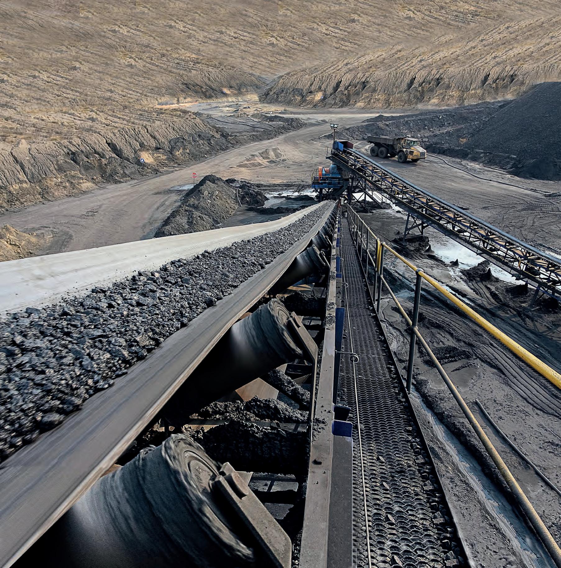
In this issue: 2023 Conveyor Showcase Highlighting local manufacturing Figuring out feed management www.bulkhandlingreview.com VOLUME 28, ISSUE 4 | JULY/AUGUST 2023

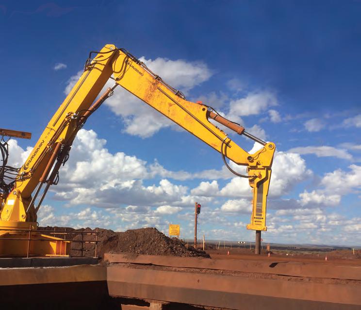




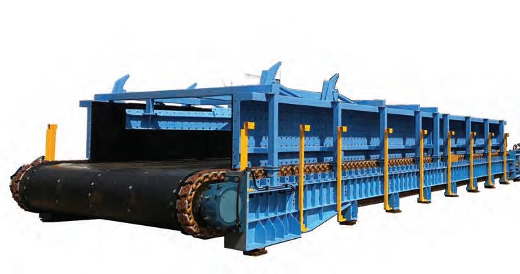
OVER 35 YEARS OF TRUSTED SOLUTIONS E: info@transmin.com.au | T: +61 (0)8 9270 8555 FOLLOW US ON: With highly innovative bulk materials handling solutions in over 60 countries, Transmin is a market leader providing quality equipment to the mining and processing industries. From plant to port, we service our diverse worldwide client base across mining operations handling Iron Ore, Gold, Copper, Lithium, Rare Earths and many other commodities. www.transmin.com.au WINNE R INNOVATION 2012 WINNE R C.Y O'CONNOR AWARD 2012 OUR AWARDS
COVER STORY: THE 2023 CONVEYOR SHOWCASE
The Conveyor Showcase highlights manufacturers and suppliers across a whole range of conveyor components and systems, in a comprehensive overview of the best of what the industry has to offer. For


CONTENTS JULY/AUGUST 2023 Australian Bulk Handling Review: July/August 2023 І 3 54 44 24 14 In this issue: 2023 Conveyor Showcase Australian made bulk equipment Figuring out feed management VOLUME 28, ISSUE JULY/AUGUST 2023
6 Industry news 14 Business as usual 16 What you don’t know can hurt you 18 Kitted out for transfer chutes 20 Five-minute blending going on four decades 22 Torque around town 24 Stress test with one of the best 26 Page Macrae crosses the Tasman 28 OPS support stacks up 30 ESS makes an impact with the cradle 32 Here to help 54 Automated CAD design to meet requirements 56 Managing conveyor feed 60 Good vibrations for mass flow 62 Optimising scrapers for improved belt performance: Addressing carryback issues 66 Dispelling the common myths about conveyor belt scales Australian manufacturing 34 Tecweigh’s local touch 36 Packed for success Conveyors 38 Finding new markets 40 Time for conveyor belts to be part of Australia’s circular economy 42 How low can Thor go? 44 Tough troughs 46 Conveying without a belt 48 Removing material from an operating conveyor belt 50 Analysing impact forces and overcoming issues in high-capacity belt support applications
the full story, see page 12.
Published by:
379 Docklands Drive
Docklands VIC 3008
T: 03 9690 8766
www.primecreativemedia.com.au
COO
Christine Clancy
E: christine.clancy@primecreative.com.au
Editor William Arnott
E: william.arnott@primecreative.com.au
Journalist
Adam Daunt
E: adam.daunt@primecreative.com.au
Business Development Manager
Rob O’Bryan
E: rob.obryan@primecreative.com.au
Client Success Manager

Janine Clements
E: janine.clements@primecreative.com.au
Design Production Manager
Michelle Weston
E: michelle.weston@primecreative.com.au
Art Director
Blake Storey
Design
Michelle Weston
Subscriptions
T: 03 9690 8766
E: subscriptions@primecreative.com.au
www.bulkhandlingreview.com
The Publisher reserves the right to alter or omit any article or advertisement submitted and requires indemnity from the advertisers and contributors against damages or liabilities that may arise from material published.
© Copyright – No part of this publication may be reproduced, stored in a retrieval system or transmitted in any means electronic, mechanical, photocopying, recording or otherwise without the permission of the publisher.
Keeping up with conveyors
Conveyors are the lifeblood of the bulk handling industry. Every day they move millions of tonnes of raw material from point A to point B. Without them, modern mines would not have anywhere close to their current throughputs, and the manufacturing industry would be almost unrecognisable.
Australia, as a major exporter of primary products, relies on conveyors of all kinds. Massive belt conveyors handle the heavy-duty iron ore, while screw conveyors feed sticky material in industrial production.
In this edition of Australian Bulk Handling Review (ABHR) we are highlighting the crucial conveyor sector, through the 2023 Conveyor Showcase. It includes several major organisations that operate within the industry and is a tool to help you navigate the different offerings available.
You can also learn about how to remove material from an operating conveyor belt, the latest in conveying equipment, a look at different kinds of conveyors, and find out how conveyor belts can be turned into new products.
Conveyors are also getting smarter, using new technologies to assist with maintenance, monitoring and logistics.
We are lucky to have several key conveyor manufacturers located on our shores. This has a variety of benefits, including reduced turnaround times, no language barriers, minimal timezone interruptions, the ability to use localised expertise and adherence to Australian Standards.
It also creates critical jobs and opportunities to develop skills locally. This has a massive flow on effect throughout the economy.
That’s why this edition also features several articles that highlight local manufacturers like Tecweigh and DYNA Engineering. Read on to find out about the benefits of buying from a local business.
Looking ahead, next month’s edition of the magazine will be featuring articles that dive into dust control, along with a deeper look at engineering services. If you’d like to get involved, please get in touch.
FEATURES
William Arnott Editor - ABHR
4 І Australian Bulk Handling Review: July/August 2023
EDITORIAL
RPM Monitoring FEATURES AND RPM FEATURESFEATURES Gateway O ce Shell Wear Detection Real-Time 24/7 Wireless Monitoring Acoustic Monitoring RPM Monitoring FEATURES AND BENEFITS header Gateway O ce Shell Wear Detection Real-Time 24/7 Wireless Monitoring Acoustic Monitoring RPM Monitoring FEATURES AND BENEFITS header Gateway O ce Shell Wear Detection Real-Time 24/7 Wireless Monitoring Acoustic Monitoring RPM Monitoring FEATURES AND BENEFITS header Gateway O ce Shell Wear Detection Real-Time 24/7 Wireless Monitoring Acoustic Monitoring RPM Monitoring FEATURES AND BENEFITS header Gateway O ce Shell Wear Detection Real-Time 24/7 Wireless Monitoring Acoustic Monitoring RPM Monitoring FEATURES AND BENEFITS header Gateway O ce Shell Wear Detection Real-Time 24/7 Wireless Monitoring Acoustic Monitoring RPM Monitoring FEATURES AND BENEFITS header Gateway O ce Shell Wear Detection Real-Time 24/7 Wireless Monitoring Acoustic Monitoring RPM Monitoring FEATURES AND BENEFITS header Gateway O ce Shell Wear Detection Real-Time 24/7 Wireless Monitoring Acoustic Monitoring RPM Monitoring FEATURES AND BENEFITS header
THE AUSTRALIAN RAIL TRACK Corporation (ARTC) has installed the first of two temporary steel girders for the Southern Cross Drive Bridge, as part of the ongoing Botany Rail Duplication project.
The steel girder was lifted into place by a 600-tonne crane and will allow new concrete girders to be poured in site, without closing the road below.
Each temporary girder spans 33 metres long and weighs 115 tonnes, the second girder will be lifted into place later this month, with the new bridge expected to be finished in late 2023.
ARTC general manager NSW projects, major construction projects, Julian
Richards said the Southern Cross Drive Bridge is one of five bridges the ARTC is constructing or modifying in the Botany Rail Duplication project, with major construction works for the project on track to be complete in 2024.
“Not only will this project increase freight capacity, it will also encourage more freight movements to be made by rail – helping to shift freight away from road transport and reduce truck movements and associated traffic congestion,” Richards said.
“Each extra freight train travelling on the Port Botany Rail Line will take up to 54 trucks off Sydney’s roads and that will be well received by local road users.
The $400 million project aims to deliver better access to global export markets via Port Botany and improve freight supply chains across NSW
The project will duplicate the remaining 2.9-kilometre section of single line track to Port Botany and construct a passing loop on the Southern Sydney Freight Line at Cabramatta to accommodate freight trains up to 1300 metres in length.
Preparations are also underway for major works in August, when the existing O’Riordan Street Bridge will be demolished, and a new double-track concrete bridge constructed during a fiveday rail shutdown.
Massive girders installed on Botany Rail Duplication Queensland sugarcane crush kicks off
THE 2023 SUGARCANE CRUSH is underway as growers, harvesting crews, and mills work to cut and crush Queensland’s 30 million tonnes of cane by the end of November.

Canegrowers Tableland Chairman Claude Santucci said the weather is spectacular for harvesting.
“We had a bit of a cold snap come through a few days ago, so that will help push up the sugar content a bit, although it will be a while before we start getting decent levels,” Santucci said.
“The early cut cane from last year is looking really nice…if we can keep
this weather and the mill has a good run, I’m hopeful we can have a pretty good 2023 season.”
Latest estimates put the crop at 30.55 million tonnes of cane, producing between 4 and 4.5 million tonnes of sugar, the majority of which will be exported to overseas markets in Japan, South Korea, and Indonesia.
With the world sugar price hitting record highs and forecasters predicting a drier winter this year, growers are optimistic that 2023 could be a bumper year for the industry, Canegrowers Chairman Owen Menkens said.
“Last year we were pretty optimistic going into the crush, with prices on the up and a great crop in the paddock, but unfortunately things didn’t pan out the way we wanted,” Menkens said.
“Poor weather, workforce shortages, and poor mill performance in some areas combined to cause major disruptions that ultimately led to the crush running through Christmas and well into the new year in some districts, and around one million tonnes of cane left unharvested.”
Menkens said there was a very positive feeling around the industry at the minute, with the industry on the verge of a transition to a range of new and growing opportunities in the bioeconomy that rely upon sugarcane for feedstock.
“The export of raw sugar will always be the foundation of our industry, but we know there are many other complimentary opportunities that are emerging for the industry and we hope that this coming season, combined with a strong price, will provide the basis for new and increased investment into these exciting projects.”
NEWS 6 І Australian Bulk Handling Review: July/August 2023
Work has begun across the QLD sugarcane growing regions.
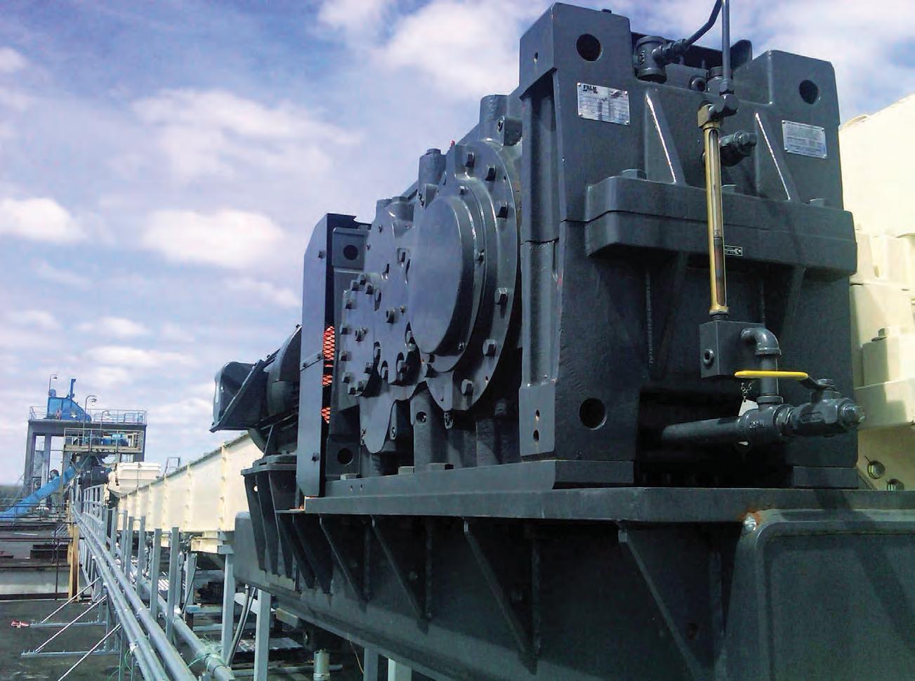
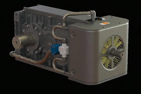
• Integrated cooling DURAPLATE™

• Drop-in footprints via customisable mounting feet
• Local Engineering Expertise
• Australian stock and assembly
• Full Rebuild facilities on East and West coasts
• Full load testing to 1mW
DURAPLATE™
Integrated gearbox cooling system
NO external coolers required
NO external power or water required
Highly durable and damage resistant compared to alternate methods
Fully self contained
INDUSTRIAL POWERTRAIN SOLUTIONS


Newcastle 02 4962 8000 | Perth 08 94124100 | Sydney 02 4677 6000 | Melbourne 03 9736 6000 | sales.australia@regalrexnord.com
ENGINEERED FOR THE LONG HAUL
Winners of the Women in Industry awards announced
THE WINNERS of the 2023 Women in Industry Awards have been revealed. The awards recognise outstanding women from across a range of industrials sectors, including in mining, transport, manufacturing, engineering, logistics, bulk handling, waste management, rail and construction and infrastructure.

The 2023 Women in Industry Awards were held at Aerial South Wharf in Melbourne.
The 2023 winners:
Business Development Success of the Year
Stefanie Frawley from TMX Global.
Stefanie successfully identified a gap in the offerings available to TMX customers, and introduced a new Portfolio Management option. As a result, Stefanie has grown her team from one to seven employees, servicing more than 14 clients in this new offering, and increased revenue from her team by 1000 per cent in the past two years.
Industry Advocacy Award
Jemma Walshe from Fulton Hogan.
Jemma advocates to ensure time, energy and resources are dedicated to making a difference to the communities that Fulton Hogan works within and has been critical to the establishment and roll out of a number of positive community engagement outcomes.
Mentor of the Year
Teagan Dowler from The BCW.
Teagan has dedicated her career to supporting women in industry. Running online coaching sessions and a career development program, she is tireless in her passion for celebrating, supporting, and developing females in
industry and has positively impacted the careers of thousands of women in Australia and abroad.
Safety Advocacy Award – Sponsored by Komatsu
Giselle Phillips from Fredon QLD.
Giselle has been instrumental in pioneering change within the Fredon QLD business; driving the use of technology to streamline the compliance of training and competencies, as well as being proactive in delivering mental health and well-being initiatives.
Rising Star of the Year – Sponsored by Atlas Copco
Sophia Kurianski from Jinolo.
In 2021, Sophia founded Jinolo, a 3D collaboration start-up that helps industrial design and engineering teams save time and money when working on designs with external clients and suppliers. Jinolo has already garnered significant attention, with manufacturing, design, and engineering teams using Sophia’s software to collaborate on 3D files.
Excellence in Transport
Coralie Chapman from Humes Concrete Products.
Coralie has always had a passion for promoting the various roles in the transport and logistics industry as well as safety around heavy vehicles. She is passionate about encouraging women to choose transport as a career path and strongly advocates for diversity and inclusion for people pursuing “nontraditional” careers.
Excellence in Engineering –Sponsored by SEW Eurodrive
Elsa Antunes from James Cook University.
Elsa graduated her PhD in chemical engineering in 2018 and in the five years
since has shown ambitious leadership and innovation in the engineering sector. She has been promoted to Senior Lecturer, received over $1 million in grants and is instrumental in creating collaborations with industry and government across a range of topics.
Excellence in Manufacturing –Sponsored by PACCAR Australia
Kristi Riordan from Harvest B.
Kristi founded Harvest B. in 2020 to help address global protein needs and sustainability concerns in our food system. With capital support from Woolworth’s venture fund, W23, she has since opened Harvest B’s first factory and a dedicated lab facility to enable rapid cycles of R&D to commercial production.
Excellence in Construction –Sponsored by NAWIC
Trudy Grimshaw from Department of Finance, Western Australia.
Trudy found her passion for construction through a winding road of career choices. Currently the Senior Project Director on the Bunbury Hospital Redevelopment, Trudy in all respects demonstrates how women can take a leading role in the construction industry.
Excellence in Mining – Sponsored by Weir Minerals
Ashara Moore from BHP.
Ashara commenced her career as a Site Engineer, working on projects Australia-wide. Her ultimate goal is to encourage people from all backgrounds to be involved in the resources sector.
Ashara firmly believes that mining can be done better – and is determined to be a part of the solution.
Woman of the Year – Sponsored by Fulton Hogan Giselle Phillips from Fredon QLD.
NEWS 8 І Australian Bulk Handling Review: July/August 2023
C M Y CM MY CY CMY K



™
Inaugural Inside Construction Expo approaches
A BRAND NEW EXPO is set to help the construction and related industries “engineer the future” of Australia.
The Inside Construction Expo 2023 will be held on the 20-21 September 2023 at the Melbourne Convention and Exhibition Centre.
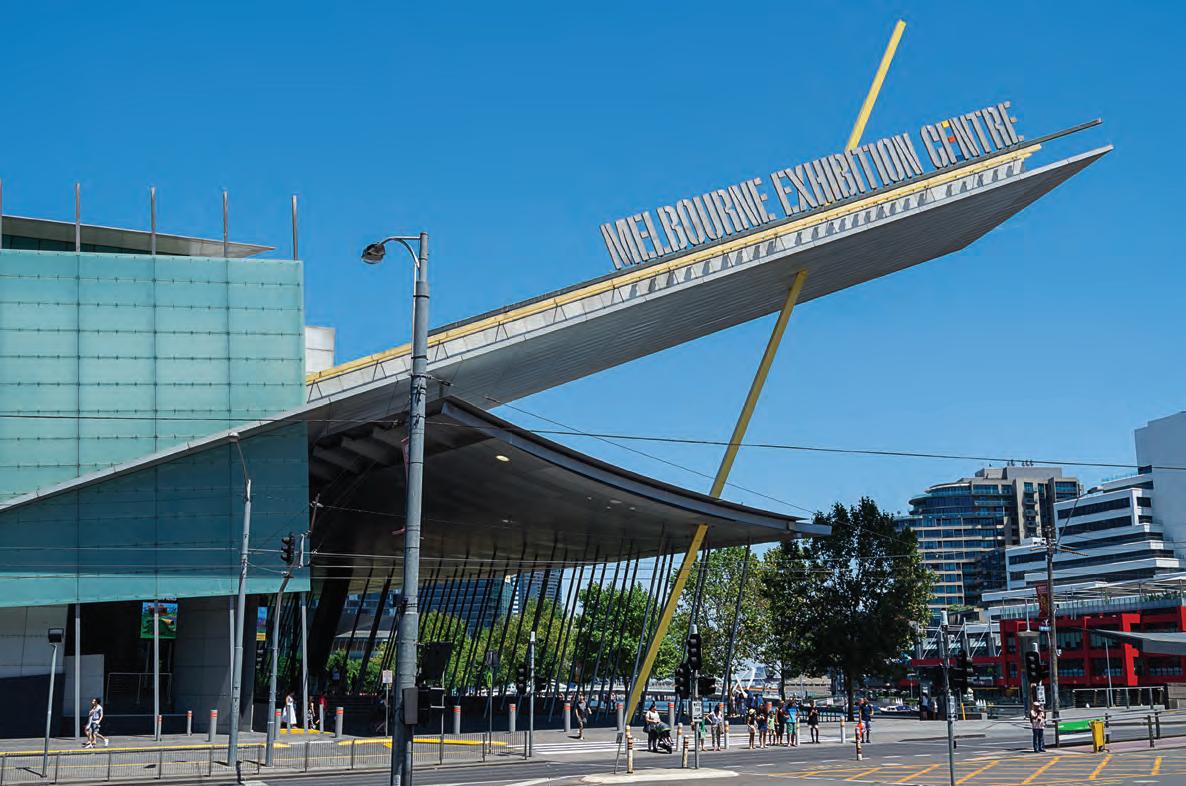
It will provide the ideal environment to present and discuss answers to the issues facing the construction industry.
Discussions regarding the skills shortage in the sector, the continuing digital transformation of the industry and safety will take place at the expo to highlight the way forward.
The conference will focus on major projects and civil construction, with the conference and world-class exhibition
providing a platform for construction equipment and companies, alongside industry leaders, to present ideas and equipment that are best suited to the current concerns in the industry.
Inside Construction Expo is backed by support from several valued organisations and media partners. Without this support, Winterbottom said, the event would not be possible.
“We’re pleased to partner with industry associations and peak bodies to bring Inside Construction Expo to life,” she said.
“Specialist in assembly and fastening materials, Wurth Australia has come on board as a supporting sponsor for the Expo.”
“We are thrilled to be part of the 2023 Inside Construction Expo, which promises to be a game-changer for the industry. This event will provide an unparalleled opportunity for us to showcase our latest products and innovations, as well as to connect with fellow professionals and share insights and expertise,” said Serge Oppedisano, CEO of Wurth Australia
Winterbottom also said positioning solutions provider Position Partners and manufacturer Komatsu have signed on as conference sponsors.
If you’d like to attend, exhibit, submit a presentation or become a sponsor visit insideconstructionexpo.com.au
NEWS 10 І Australian Bulk Handling Review: July/August 2023
The Expo will be held at the Melbourne Convention and Exhibition Centre.
Image credit: Nils Versemann / Shutterstock.com




1300 258 726 Sales I Service I Engineering Phone: 1300 258 726 Email: sales-australia@regalrexnord.com Altra Industrial Motion Australia Pty Ltd ABN 82 000 780 941 Sydney NSW Perth WA Melbourne VIC Mackay QLD Newcastle NSW Unit 1 Suite 34 Unit 14 Unit 1 11 Penny Pl 271 Great Eastern Hwy 3 Albert Coates Lane 20-34 Caterpillar Dr 18 Kinta Dr Arndell Park, NSW 2148 Belmont, WA 6104 Melbourne, VIC 3000 Paget, QLD 4740 Beresfield, NSW 2322 Ph. 1300 258 726 Ph. 1300 358 26 Ph. 1300 258 726 Ph. 1300 258 726 Ph. 1300 258 726 www.regalrexnord.com www.altramotionaustralia.com

CONVEYOR SHOWCASE 12 І Australian Bulk Handling Review: July/August 2023 Business Details
type of conveyor do you manufacture? Company Name Company Email Address Company Phone Number Belt Screw Chain Pneumatic AGI apac@aggrowth.com (+61) 477 474 726 •••• BEUMER Group GmbH & Co. KG info@beumer.com (+61) 2 9450 0380 • • Bridgestone Mining Solutions Australia461 Dundas Road, Forrestfield, WA 6058(+61) 400 066 505 • Bruks Siwertell magnus.rundqwist@bruks-siwertell.com (+1) 770 849 0100 ••• Bulk Connections sifison@bulkconnections.com (+27) 3 1466 9618 •••• Continental Conveying Solutions www.continental-industry.com (+61) 03 9720 9428 • Conveyor Manufacturers Australia ajolly@cmacv.com (+61) 2 8358 8660 • CRP Industries sales@crpindustries.com.au (+61) 3 9768 2228 Diacon Australia reception2@cpeqld.com.au (+61) 7 4957 2472 Dos Santos International, LLC info@dossantosintl.com (+1) 770 423 9895 • DYNA Engineering dyna@dynaengineering.com.au (+61) 8 9473 4300 • Finlay Screening & Crushing ggrigson@finlay.com.au (+61) 7 388 81777 • Flexicon Corporation (Australia) PTY. LTD. sales@flexicon.com.au (+61) 7 3879 4180 • • Hyer Industries Inc desmond@thayerscale.com (+1) 7 8182 68101 JET Materials Handling Pty Ltd admin@jetmaterialshandling.com (+61) 4 2811 6368 •• KAUMAN kauman@kauman.com (+34) 6 7875 4615 • Kinder Australia Pty Ltd conveyorsolutions@kinder.com.au (+61) 3 8587 9111 Martin Engineering info@martin-eng.com (+1) 309 852 2384 • Nilos Australia Pty Ltd info@nilosaustralia.com (+61) 4 3908 2080 OREFLOW AUSTRALIA PTY LTD chrisc@oreflow.com.au (+61) 4 3999 3484 • Premron Pty Ltd sales@premron.com.au (+61) 7 4972 2982 ••• Promet info@promet.com.au (+61) 8 9249 8749 ProStack - A Terex Brand ProStack@terex.com 028 7122 3110 • Qetra admin@qetra.com.au (+61) 6209 7712 • R BRUNONE commercial.brunone@brunone.fr (+33)2 3264 2020 REMA TIP TOP communications@rema-tiptop.com.au (+61) 4 2360 8343 • RKM sales@rkmrollers.com.au (+61) 8 6558 1287 •• STMalnati S.a.s. info@stmalnati.com (+39) 02 8950 1730 • Tecweigh Pty Ltd barry@tecweigh.com.au (+61) 4 3016 6444 Thayer Scale Sales@ThayerScale.com 781 826 8101 •• Transmin ConveyorPro aftermarket@transmin.com.au (+61) 8 9270 8555 ••• TUNRA Bulk Solids enquiries@bulksolids.com.au (+61) 2 4033 9055 VAYERON info@vayeron.com.au 1800 404 160 • WA Belting Solutions david@wabelting.com.au 1300 651 320 • WAM AUSTRALIA alessandro.bini@wamgroup.com (+61) 3 9737 4700 •••
What
What type of conveyor components do you manufacture/distribute?

Australian Bulk Handling Review: July/August 2023 І 13
Idlers Rollers Scrapers Belts Pulleys Pulley Lagging Walkways Lacing Skirting Guards Impact Beds Wear Panels Consulting Testing Maintenance Belt Scales Dust Collectors ••••• •••• •••• •••••••••••• • ••••••••• •••••••••••• •••••• • • • •• • • ••• • •••••••••••• • • •••• •• • •••• ••••• •• • ••• •• •••• ••• ••••• • • • • •••••• • • • •• ••••••••• ••••• •••• •••••••••••• • •••••••••••••• • • ••• •••••• • ••••• •• •••••• •• • ••• •••••• •• ••••• •••••• ••••• •• •••• •• •••••• •• • ••• •
Business as usual
Regal Rexnord has acquired Altra Industrial Motion. ABHR learns what the move will mean for the Australian bulk handling industry.

in Australia right now is brakes and clutches,” he said. “It’s important as an organisation that we don’t lose that focus. As you get bigger, if you get too distracted by other things, you lose your focus.
“From a strategy point of view, Regal Rexnord has really left us to continue on our growth initiatives and ensuring that we keep supporting and our customers.
“Down the line, there’s obviously some synergies that we can work on with our sister companies; however, particularly for us, we’re very much business as usual and Regal Rexnord has really given us the autonomy to continue doing what we do best.”
Altra Motion designs and manufactures a wide range of highly engineered motion control, automation and power transmission solutions across its 26 brands, including Svendborg Brakes, Twiflex, Marland Clutch, Wichita Clutch, Industrial Clutch, and Stieber.
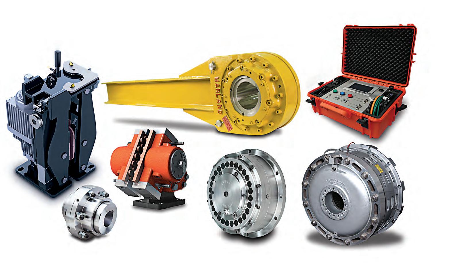

It also brings with it a strong Australian client base, with customers throughout the bulk handling sector.
Eltagonde said the culture of both Regal Rexnord and Altra Motion has a strong focus on respecting and supporting its people to ensure employees get the best out of themselves colleagues.
“Regal Rexnord’s focus right now is about promoting within, utilising our talents within the organisation and
ACQUISITION 14 І Australian Bulk Handling Review: July/August 2023
IN 1980, James L. Packard and Henry W. Knueppel joined an American tool service capability, technology content and domain expertise.
Altra Motion Australia has facilities across the country.
Altra Motion designs and manufactures a wide range of motion control, automation and power transmission solutions.
Designed for industrial sectors INDUSTRIAL VIBRATORS
OLI is the world’s top selling manufacturer of electric and pneumatic vibrators. The high level of customer service, guaranteed by 18 trading subsidiaries worldwide, and long-lasting and performing products make us always ahead.
Our vibrators are designed for industrial applications in all sectors, from the most extreme environments such as quarries, mines and foundries to the food and pharmaceutical.


OLI Vibrators Pty Ltd. 7 Jellico Drive, Scoresby Vic 3179, Australia - Phone: +61 3 9764 9988 - Mail: info@olivibrators.com.au - www.olivibrators.com.au
What you don’t know can hurt you
Rollers and idlers are often in locations that are difficult to inspect, but if they fail the costs can be catastrophic. Vayeron’s technology helps spot these issues well before they escalate.
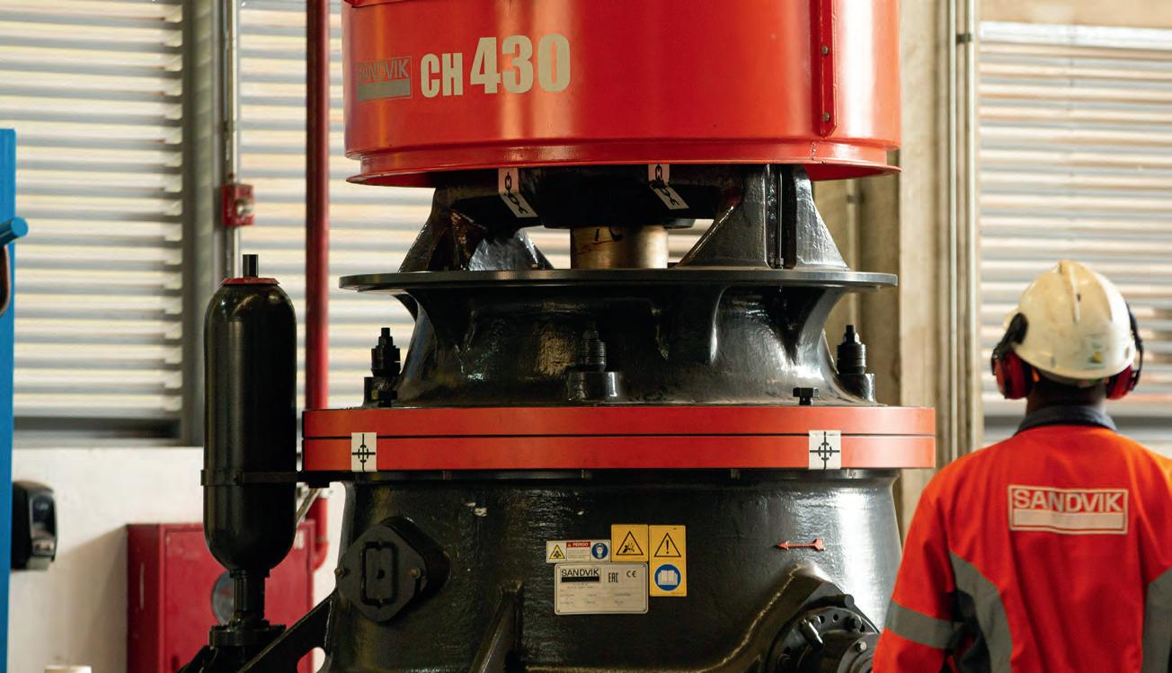
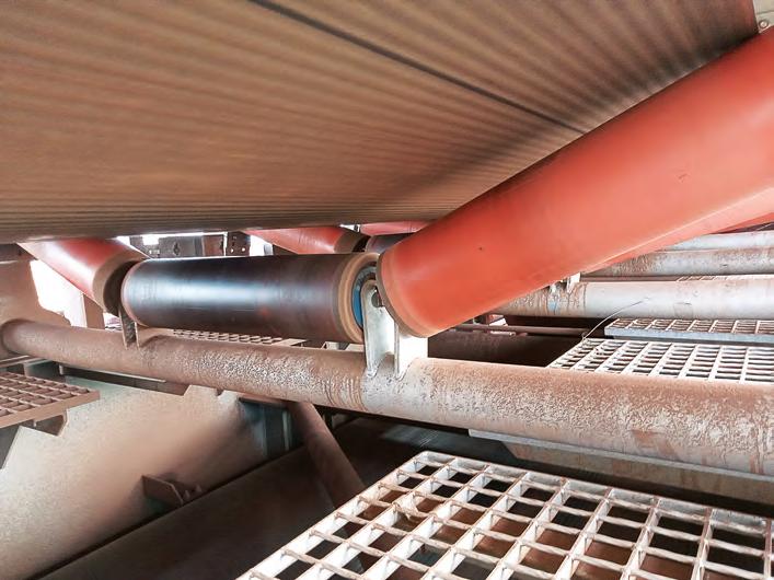
ROLLERS PLAY A CRITICAL ROLE on mining sites and need to withstand exceptional punishment from the harsh Australian elements and massive throughputs.
However, they can be difficult to inspect properly. A proactive manual inspection regime can help spot carryback and defects, but is unlikely to eliminate them totally. There is only so much a person can see or access, and a lot happens within a roller that is almost undetectable.
Small problems inside these rollers can grow into major issues, and potentially catastrophic failure.
Ryan Norris, Vayeron’s co-founder and chief executive told ABHR about a shiploader that caught fire due to a malfunctioning roller. The resulting blaze took out a significant chunk of the port’s iron ore loading capacity and had a massive financial impact on more than just the miner.
“There was a butterfly effect – because the miner had reduced productivity, it had flow on effects on the iron ore spot market prices. Events like these don’t happen very often, but can cost hundreds of millions of dollars,” he said.
installed inside of a roller to ensure events like that never happen.
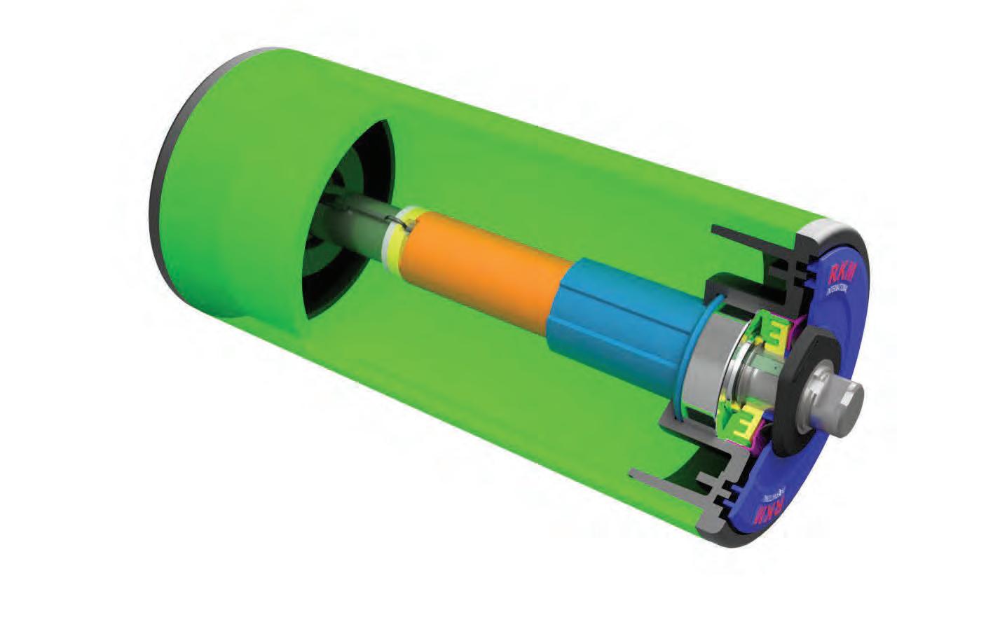
Harvesting the rotational energy of the roller, the maintenance-free device monitors the roller, including vibration, bearing temperature, shell wear and carryback build up.
Norris said the rollers allow for insights that previously weren’t possible.
“The smart sensors allows sites to monitor, predict the performance of, and optimise the rollers, rather than having to rely on adhoc replacements or bulk changeouts,” he said.
“It means you can treat each
the need for employees to get up close with heavy machinery to inspect them. On many mine sites, rollers can be in enclosed or elevated areas, making them risky to inspect.
The technology acquires data from the rollers, which can then be used in third party systems such as a control system or a digital twin. Elaborate analysis can be performed on the data, allowing mines to derive insights into the operation.
Norris said the industry is moving towards digital solutions and aims to anchor what is occurring in the physical world with the digital.
“Digital insights can support maintenance to allow for a leaner operation – an important thing to consider when you see the high turnover rate of staff in the mining industry,” he said.

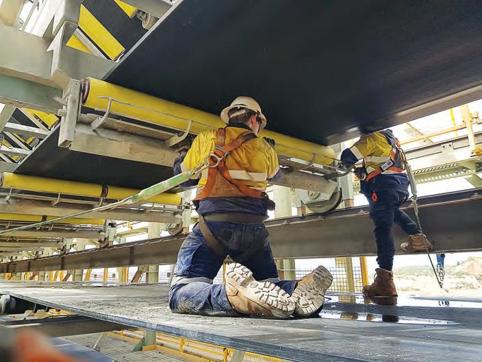
“Our application programming interface allows other technology to use the data that has been gathered to create more effective insights.
“There’s an information gap that we are filling with our smart rollers. They can gather data from along the entirety of a conveyor and use that wealth of information to support the entire operation.”
CONVEYORS 16 І Australian Bulk Handling Review: July/August 2023
Vayeron’s technology can monitor vibration, the temperature of bearings, shell wear and carryback build up.
A monitoring cartridge can be installed inside of a roller to collect data.
Combined expertise
Schenck Process Mining has become part of Sandvik Rock Processing Solutions.

Combining the expertise and reach of our teams allows us to develop even better services to ensure that your equipment operates safely and at peak performance throughout its entire lifecycle.
We are now better positioned than ever, to develop innovative solutions to the challenges of our industry.

ROCKPROCESSING.SANDVIK
Watch this video to learn what this new parternship means to your business or visit our website:
Kitted out for transfer chutes
Martin Engineering has made difficult modifications and lost inventory a thing of the past with its new transfer chute kits.
MOST COMPANIES KNOW the pain of lost inventory all too well. They have ordered a new transfer chute but when it arrives, the parts do not arrive together and come in multiple boxes of various sizes.
With the best intentions, companies set aside inventory until the scheduled downtime when the chute can assembled. Some inventory vanishes and companies are left to deal with the headache.
Martin Engineering has unveiled a transfer point kit designed to address three common issues the bulk handling industry faces: product loss, difficult assembly, and expensive retrofits.
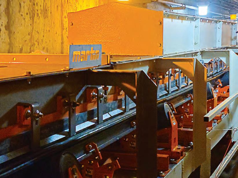
The company knows product loss can lead to delays and has designed its new transfer point kit to be delivered in a single crate with all assembly parts included.
“This is a rugged one-kit solution designed to fit most standard conveyors and belt widths, regardless of what material is being transferred,” said Martin Engineering’s conveyor products manager, Dave Mueller.
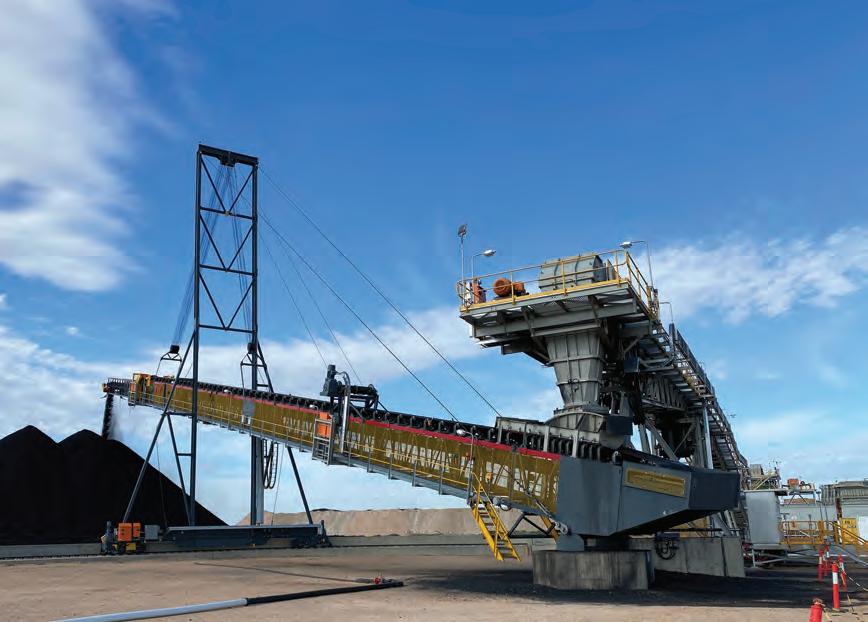
“Our centre for innovation is constantly looking for ways to engineer equipment with safety and our customer’s bottom line in mind.
“That’s why the kit doesn’t just streamline labour, time and production, but it’s also a logistical solution by shipping it in one crate.”
While most new chutes need to be fabricated in downtime – which increases project budgets and extends production time – the transfer point kit takes a new approach. The kit can be assembled before shutdown and installation, easing the impact on the customer.
Complete with a fully modular design, the new product can be retrofit with future changes without the expensive cost seen with other transfer chutes.
If customers involve a Martin Engineering technician in the installation process, they will receive the company’s “Absolutely no excuses guarantee” which promises quality products and service to the customers’ satisfaction.
Muller said the company had received plenty of positive feedback from customers about its new and innovative product.
“After installation, Martin territory managers or partner distributors are available to offer support,” he said.
“The feedback for the kit has been excellent. Customers get the heavy-duty Martin quality they’ve come to expect in a more convenient, efficient and sustainable package.”
CHUTES 18 І Australian Bulk Handling Review: July/August 2023
An efficient transfer point starts with a modular enclosure but also has excellent belt support and sealing accessories.
Modular transfer point kit can be easily modified to adapt to changes in production.
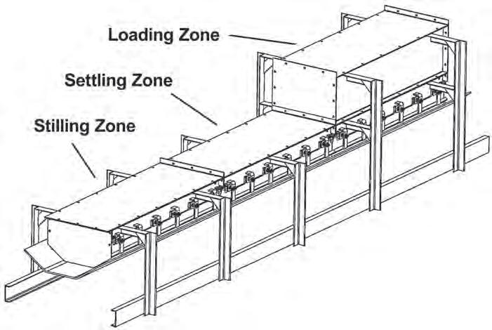
The kit features modular horizontal loading zone, settling zone, and stilling zone configurations, providing easier installation and a wider variety of chute options while facilitating future upgrades.

The skirt seal – the most frequently replaced wear part on transfer points - is sold separately as a single piece that runs the entire length of the chute.
Each kit is ordered as a loading zone, settling zone and stilling zone. Dustier applications may require a longer settling zone. The size of the kit is determined by the receiving belt’s speed and width –accommodating 450-1800 mm.
The taller loading zone controls air turbulence and connects to both the drop chute and settling zone. When cargo hits a belt with great velocity, fines and lumps splash up the sides of the belt.
Without a properly sealed enclosure, the material will spill underneath the conveyor, creating a hazard, restricting access and fouling other components.

The settling zone follows the loading zone and helps mitigate dust emissions.
filtered, or settled back into the cargo stream before leaving the stilling zone and continuing as a conventional conveyor.
weldment, wear liner assembly, wear liner plate, outer chute supports, top cover, tail panel/clamp/rubber sheet, installation hardware and an owner’s manual.

THOR TOWERSTACKER™
Telescopic Cable Mast Conveyor
• Versatile, affordable conveyor solution

• Quick and cost-effective installation
• It can be lowered to the ground to provide easy access for maintenance
• No head or tail undercarriage provides greater clearance under the conveyor
• Complies with all relevant Australian Standards, AS1170, AS4324.1 and RPEQ requirements
SALES | HIRE | SERVICE | PARTS 1800 182 888 | www.lincom.com.au | sales@lincom.com.au | OFFICE LOCATIONS | QLD | N QLD | HUNTER REGION | NSW | VIC | WA
We bring the world’s best material handling equipment to you.
REDUCE DOWNTIME. INCREASE PRODUCTIVITY.
Outer chute supports are provided in standard lengths and cut shorter or narrower on-site as needed.
Five-minute blending going on four decades
Two mixers installed 40 years ago have helped the US-based Plastics Engineering Company manufacture its range of custom-formulated moulding compounds and industrial resins.
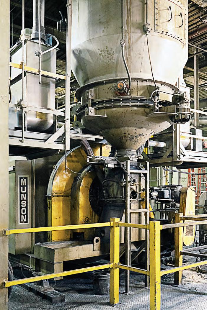
A LARGE PORTION of the Plastics Engineering Company’s production is dedicated to novolac and resol thermoset moulding compounds—also known as phenolic resins.
These resins are highly adaptable and used across many applications. As a result, the company tailors its products to each customer’s requirements. That could
entail adjusting the molecular weight, moisture content, viscosity, pH, particle size, reactivity and other properties.
Immediately prior to packaging, the resins are blended with reinforcements, minerals, fillers and/or liquid additives, a task performed by two model 700-TSC180-MS Rotary Batch Mixers which have
Five-minute tumbling prevents degradation
The mixers have no agitators, internal shafts or related bearings or seals. Instead, a horizontally oriented vessel rotates on external trunnion rings located at each end. Ingredients flow into the vessel through a stationary inlet at one end and discharge through a stationary outlet at the other. Within the vessel are mixing flights, also called baffles or lifters, which create a gentle four-way tumble-turncut-fold mixing action that produces onspec blends in three to five minutes.
“We get a good, thorough blend without degrading the product,” Randy Block, a mechanical engineer at Plastics Engineering, said.
To fill the vessels, a pneumatic conveyor transports resins from compounding units to a holding hopper, which also separates out dust. When enough material accumulates in the hopper, it is discharged to one of the mixers as it slowly rotates.
After the mixer receives a dose of powdered additives from a loss-ofweight hopper above, a valve stops the flow and the mixer makes a preset number of revolutions. When called for, liquid additions are pumped through spray nozzles onto a wide bed of moving material within the mixing vessel. At the end of the batch cycle, the mixer’s discharge gate opens while the vessel is still rotating. This allows the mixing baffles to guide the batch toward and through the discharge gate with little or no residual.
“They do a good job of moving the material quickly and efficiently,” Block said. “If we’ve got a straight dry material, there isn’t much to clean out.”
The gentle mixing action is critical, Block said, because it preserves product quality.
BLENDING
To fill the vessels, a pneumatic conveyor transports resins from compounding units to a holding hopper.
“We get a good thorough blend but we don’t degrade the product. If we used a typical paddle mixer, we would grind the granules against each other and create dust. That doesn’t happen here.”
Continuous rotation of the drum during discharge prevents stratification of ingredients having disparate sizes, shapes and bulk densities, and empties the batch rapidly in a steady stream.
“That’s important because it minimises wait times at the packing stations,” Block said. “Because of that quick discharge, we are more efficient when packing bulk containers.”
“We’ve made the same product as a 2,268 kg order and as a 113,398 kg order. And blending is just as uniform on short runs as it is across larger ones.”
The mixing flights also create a dynamic bed of material, ideal for incorporating liquid additions.
“We get a good consistent dispersion. The product doesn’t get too wet in some parts and less wet in other parts,” Block said. “A typical paddle mixer would give us a less even coating.”
Since their installation in 1983, the mixers have rarely been idle. Over the last 12 years, one mixer has had 34 hours of downtime and the other just 4.5 hours.

“The longevity of the machines is a testament to my predecessors, who selected them,” Block said. “We’ve been pleased with the lack of downtime and maintenance costs.”
Services:
Flow Properties and Materials Testing
Dust (environmental) Testing
Wear Testing (Impact, Abrasion and Erosion)
Conveyor Belt and Idler Roll Testing
Custom Numerical Simulation and Calibration Testing
Materials Handling Consultancy and Contracted Research


Bin and Stockpile Design
Pneumatic and Hydraulic Conveying
Technology and Knowledge Transfer
Site Visits
Professional Development Courses
TUNRA Bulk Solids develops custom solutions to suit the individual needs of our clients.
World leaders with over 45 years’ experience in Bulk Materials Handling Research and Consulting
www.bulksolids.com.au +61 2 4033 9055 2023 Course Dates: Storage, Feeding, Transfer and Belt Conveying 14th - 16th November (Perth) In-house customised courses available on demand contact Danielle.Harris@newcastle.edu.au
The hinged access doors at either side of the vessel provide access to all material contact surfaces for cleaning and visual inspection.
Torque around town
All Torque Transmissions has expanded its operations across the east coast and are planning to grow even further.
CRAIG MIGHELL IS PASSIONATE about power transmission. He started working with the technology when he was just a 15-year-old and has built upon this lifelong dedication with his business – All Torque Transmissions.
First opening Friday 13th in 1996, he told ABHR about how he grew from the spare bedroom at home, into an east coast spanning business.
“I realised there was a distinct lack of specialist power transmission knowledge in Victoria and across the east coast,” he told ABHR
“A lot of companies try to sell a bit of everything. There’s a filtration that happens over time when not enough people are trained in certain areas. They leave the industry or change jobs, and then that knowledge is harder to access.
“We have homed in on power transmission, which is why our staff are educated to be specialists.”
All Torque Transmissions has grown from a one-man operation into a 26-person team, with staff members trained across multiple disciplines in the power transmission field. This means if someone is absent or is sick, there is always another teammate ready to fill in
Bonfiglioli, WEG, Baldor, Comintec, Warner Electric, KB Electronics, Flender, Dodge, and many more.
“I can’t think of a single power transmission supplier we don’t have access to or deal with. And because we’re an independent business, there are no conflicts of interests – we only find the right solution for the application,” he said.
“We pass on that support to our customers, and make sure they can ring any of our staff, at any time of the day. We offer 24/7 availability across all branches.”
The company operates out of four branches, two in Victoria in Braeside and Preston, one in NSW, in Queensland.
The QLD branch was set up following the acquisition in 2021 of Engineering Transmission Agencies (ETA) which operated similarly to the Victorian and NSW branches of All Torque.
Mighell said most existing ETA staff decided to stay on with management.
ETA, the branch has grown significantly in the past two years, with further potential, thanks to its in-house gearbox and geared motor assembly facility.
The plan is to continue that growth in the northern states and expand into the local market. The company will increase the amount of available stock, and expand its offering to the mining, grain handling and food and beverage sectors.
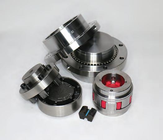
It is also now the national distributor for Flender’s shaft coupling range and has spent the past 18 months ensuring it had enough stock to roll it out to the industry.

Mighell said the timing is right for All Torque Transmissions, which has big ambitions for the future.
“We have a very good, Australia wide coverage for the whole gamut of power transmission equipment,” he said.
“Customers can also benefit from our wealth of information – if they have a question about a brand or component, it’s likely that one of our team will know the answer. That kind of expertise you just can’t get from a search engine.”
POWER TRANSMISSION 22 І Australian Bulk Handling Review: July/August 2023
The company has the backing of several key suppliers.
All Torque is the national distributor for Flender’s shaft coupling range.
MODULAR IMPACT BEDS!
When large, sharp lumps strike the conveyor, belt damage occurs at load zones. This results in premature component failure through belt punctures, damage to idlers and structure, and decreased material
Installing impact beds at load zones reduces damage to the conveyor belt, surrounding structure and idlers. Other advantages include effective belt sealing, which reduces material spillage and reduced belt
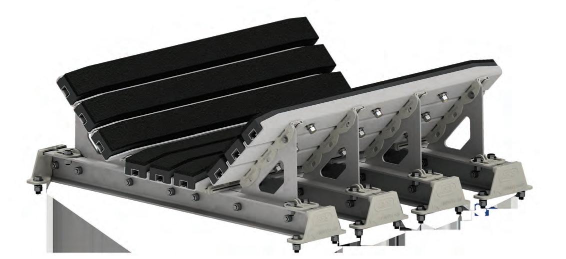
ESS introduces a new modular impact bed design for medium and light-duty applications!
ESS Modular Impact Bed features include;
• Modular support frames for easy maintenance
• Polyethylene surface to reduce friction
• Rubber body to absorb impact
Benefits of the ESS Modular Impact Bed include;
• Shorter manufacturing & lead time
• Suitable for a wide range of conveyor belt applications
• Reduced downtime
• Reduced maintenance and repair costs
FOR MORE INFORMATION ABOUT ESS IMPACT CRADLES VISIT
WWW.ESSENG.COM.AU

SERVICES
Australian
ENGINEERING
& SUPPLIES PTY LTD Ph: 1800 074 446 www.esseng.com.au Proudly
Stress test with one of the best
Bulk Solids Modelling is using a specific type of modelling to take away the stress when looking for the right bulk handling equipment.
WHEN PETER DONECKER developed dynamic scale modelling (DSM), he knew it had potential. So much so that it eventually led to the creation of his company, Bulk Solids Modelling.
“We were looking at wear materials in mining operations in general and in the course of that we noticed that a very small change in the geometry of the chute had a massive effect on the wear behaviour,” he told ABHR
“That’s when the penny dropped that it is not just the materials but how the ore flows.
“We thought how we can do this in a lab and came up with the idea for scale modelling.”
There is a perception in the industry that it is necessary to use some form of scaled down version of the actual ore in a model, but Donecker has sought to change that.
He believes to run a fully accurate simulation, a material made specifically for the situation at hand needs to be used to replicate real-world usage.
The method has proven successful with Bulk Solids Modelling having worldwide reach after working with clients in Brazil, Canada, Africa and Asia.
“The first conceptual leap that people have to make is that density is not an issue… because we’re using Froude number scaling and the Froude number does not change with density, it is independent,” he said.
“The real issue is when you take a cohesive material, like a sample of iron ore, and create a material that is one-tenth the particle size, it will be extremely cohesive, but we want the cohesion to move in the other direction.”
For an accurate test and demonstration of a chute’s capabilities, the cohesive forces need to stay in the same proportion to other forces like the inertial force.
However, the finer cohesive material gets the more cohesive it gets. This can cause a material to agglomerate and
display much higher cohesive forces which impacts the testing results.
This is why Bulk Solids Modelling uses custom materials and moisture control in its testing to ensure consistent results.
“We’ve got material that does not agglomerate, and we can control the cohesion via the moisture content,” Donecker said.
“Because of this, we can explore a whole range of cohesive conditions (accurately), starting off with low moisture content and then increasing it.
“We can see what happens and sort of stress test the situation.”
Donecker’s method has revealed other significant advantages which could benefit the bulk handling industry.

Using DSM serves as a point of difference to validate DEM results and shines a light on previously unforeseen issues with chutes.
“The advantage of using scale modelling is that you can check the design that you have done in DEM with a completely different approach… that gives you the extra confidence you got it right,” Donecker said.
With nearly 30 years in the industry, Donecker has seen plenty of companies caught out with an ineffective chute.
If a transfer chute does not work as planned, it becomes a major headache worth significant sums of money. For example, if the chute is dispersing an uneven load the cost to fix the imbalance,
SIMULATION 24 І Australian Bulk Handling Review: July/August 2023
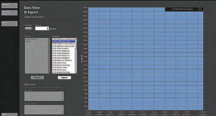
Screen capture of process monitor showing real-time throughput measurement.
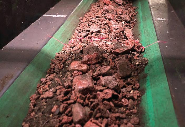
View of the line from the laser scanner on the belt running simulated iron ore.
alongside the associated downtime and preparation time, brings in a hefty bill.
“You may have spent a million dollars for the chute which is one cost but if you can’t process your ore through it, it can cost many millions of dollars,” Donecker said.

“For example, if you’re processing 18,000 tonnes of ore per hour, every minute you can’t do that is worth a lot of money.
“It’s quite a big deal and you’ve lost all the production time while they’re fixing it and it may not (fix the problem).”
To avoid this crippling situation, Bulk Solids Modelling allows customers to try before they buy with scale models.

Peter and the team can make tweaks to a model using a laser cutter and Perspex, enabling companies to see the impact of the alteration in real-time.
“This way you’ve got everyone gathered together at the one time, looking at the model and everybody’s making suggestions in real-time, and out,”
The main reason Donecker and his team can deliver these changes in real-time is because the DSM method offers significant time-saving measures compared to alternatives.
With DEM, simulations can be run for 24 hours after the inputs are set before it must be run again to test another set of inputs. The result is timeconsuming and intensive.
The company’s fully instrumented system can process simulations in 20 minutes and run through a year’s worth of DEM simulations in a fraction of the time.
“This is one of the big advantages, a scale model runs faster than a full-scale chute because of the way time scales,” Donecker said.
“The analogue system is vastly faster than the digital systems.”

The Western Australian company is always looking to remain on the cutting edge and save its customers’ time.


of the most crucial factors is the
The ability to accurately assess throughput rate and peak capacity is vital in an industry built around delivering commodities into supply efficiently.

The downside is it can take significant time to measure the throughput with the need to crashstop the circuit and conduct a belt cut before emptying out the whole system and starting again.
Donecker estimated the process used to take a whole day’s work until the company developed a laser scanning system to tackle the issue.
“By using this real-time throughput measurement we’ve cut down what used to be a whole day to just a couple of hours, it is an absolutely huge improvement,” he said.
“I’ve had cases where the whole test program is completed is finished in two hours (because of this scanner).”
While these factors may sound simple, Bulk Solids Modelling has put in the work to ensure a fast and efficient
Scan me on your Phone for more information PHONE: 1300 400 MPS WWW.MPSAUS.COM.AU AVAILABLE IN: WA NT SA QLD NSW TAS VIC sales@mps.com.au ONE OF THE WORLD’S LARGEST STOCKS OF PREMIUM, TELESTACK BULK MATERIALS HANDLING EQUIPMENT
Page Macrae crosses the Tasman
After supporting Australian ports for more than 10 years, Page Macrae Engineering is now expanding onto local shores. ABHR finds out why it is targeting local shores and how it will benefit bulk handlers.
NEW ZEALAND-BASED port equipment manufacturer Page Macrae Engineering, has been involved in the Australian market for more than a decade. Now, they have taken a major step to bridge the gap across the Tasman Sea, setting up in Victoria.
Pioneering this development is Charles Hennessy, who will oversee a streamlined spares distribution service and the development of the company in Australia.
GM of Sales and Marketing, Peter Swan told ABHR that Page Macrae Engineering are very proud to be employing their first in-country Aussie national and starting the journey of local Australian customer support.
“We believe that these first local support steps will eventually lead to a much larger comprehensive presence in Australia,” he said.
Stocking the right spare parts requires an understanding of our customer’s service cycles and what equipment is in each location. That’s why Hennessy has been spending time traveling around the country and visiting ports.
“We have been meeting with our customers to help understand their requirements for spare parts and learning what solutions they need,” he said.
“Keeping our customers happy is the main aim, and we’re using their feedback to build plans for growth.
“If customers have upcoming contracts they’re applying for, we want to make sure we’re giving
Page Macrae’s growth aspirations are not just in the parts and services side of the business. Business Development Manager – Product Solutions, Bruce Ennis talked with ABHR about developments in its new products funnel.
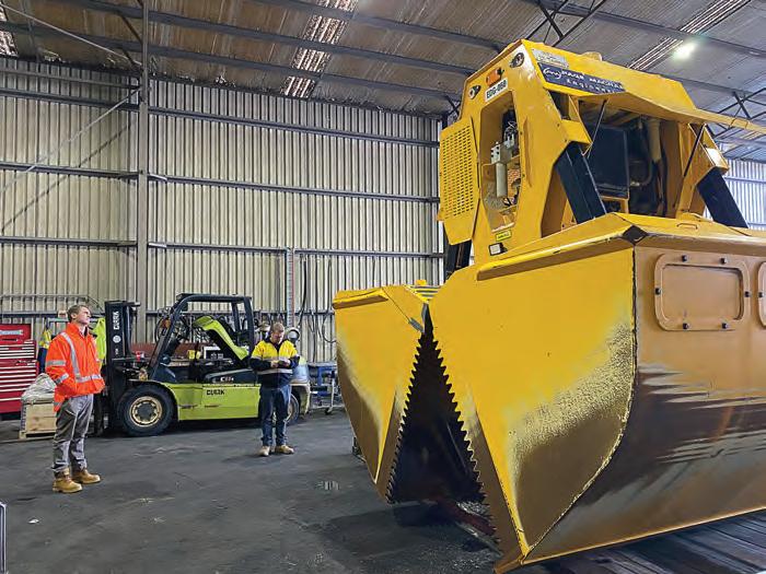
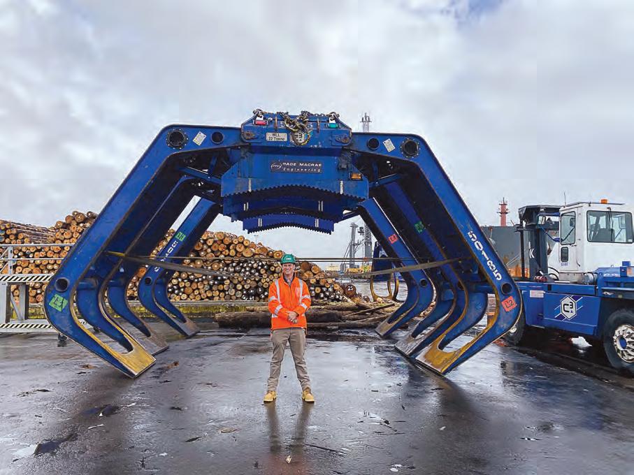
Ennis said Page Macrae Engineering is very excited about the range of new products ut will be bringing to its Australian customers, with a focus on new technology in bulk material ship unloading and log-handling equipment.

“We also hope to further develop our container loading and unloading products soon and Charles with his strong logistics background, will play a key role in bringing these products to market,” he said.
The new product funnel and service focus for Page Macrae Engineering comes after a time of business realignment for growth. New product designs are being driven by the day to day conversations they have with clients rather than a design team sitting in the office.
PORTS 26 І Australian Bulk Handling Review: July/August 2023
Page Macrae Engineering designs grabs for bulk handling and log handling applications.
New product designs are being driven by the day to day conversations with clients.
Safeguard your operations
& reduce washdown splashback
HDPE Conveyor Guards


ROBUST ✓ LIGHTWEIGHT ✓ ECONOMICAL ✓
DYNA Engineering has developed a “chamfered mesh pattern”, designed to reduce washdown splash back and increase visibility through the guard panels.
This design feature is a major “point of difference” compared to standard HDPE mesh and will improve inspection and cleaning operations.
Washdown Mesh
• Up to 50% additional spray-through for washdown.
Increased Visibility
• Up to 25% additional viewing angle and see-through viability.
1800 801 558 dynaeng.com.au
Washdown Mesh Standard Mesh
OPS support stacks up
Solving on-site issues can be a tricky task. ABHR learns how the OPS Group helps take the stress out of the process.
SOLVING ON-SITE ISSUES can be a tricky task. Oftentimes, customers are not aware of the simple solutions available within their industry. The OPS Group, however, is changing that by helping take the stress out of the process for bulk handling operators.
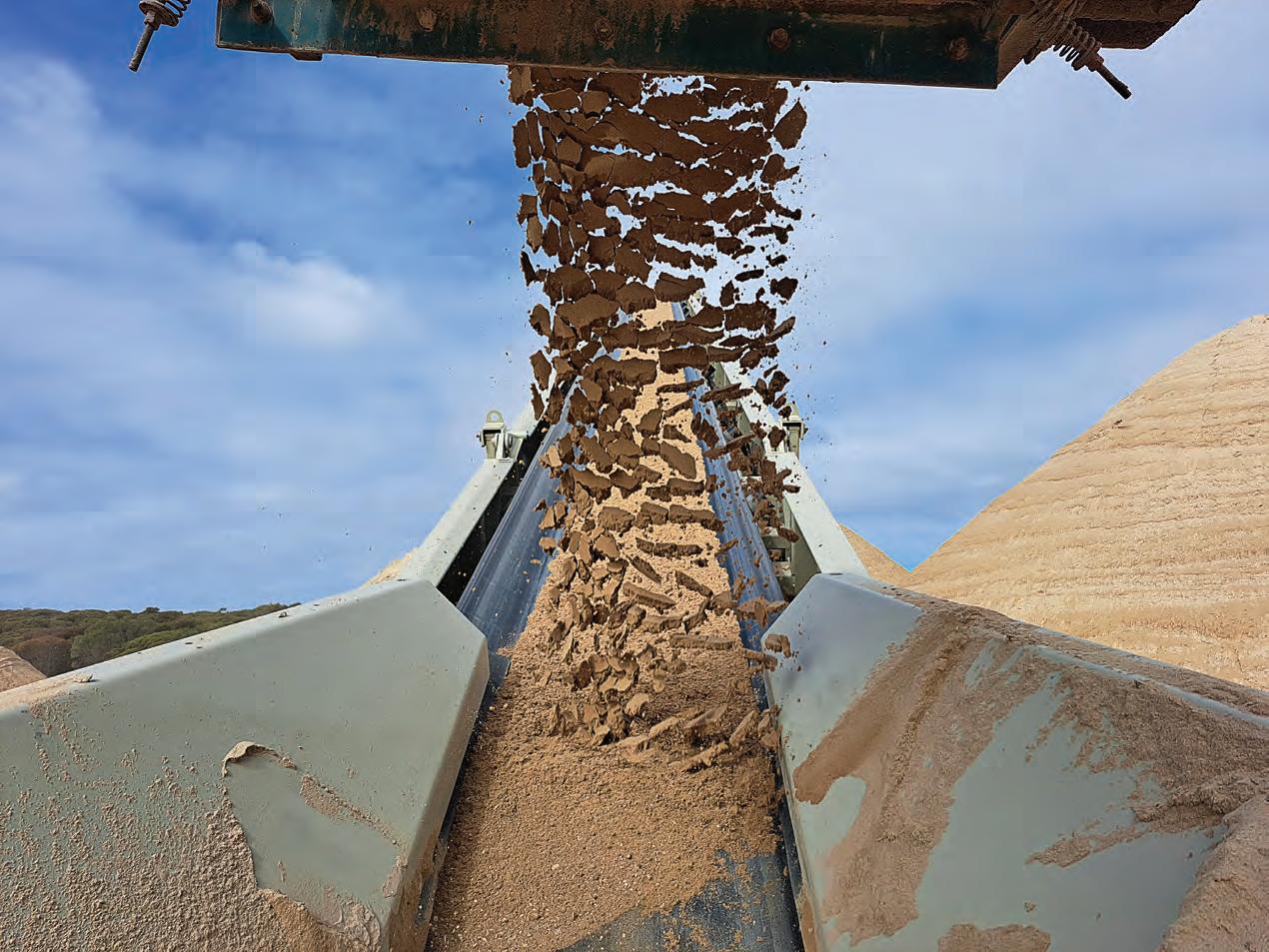
What seems like a small change could have unintended consequences or require expensive workarounds and downtime. In some cases, the plant team might find the task of changing things too daunting entirely.
Sean Burke, area manager at the OPS Group, told ABHR that often these seemingly complex engineering quandaries have a simple solution.
The problem, he said, is that operators are often not well versed in the equipment that’s out there.
“For example, we had a customer that needed to move material behind a retaining wall. There was limited space on the site, and they didn’t know how to do it,” Burke said.
“We were able to provide a solution with equipment we had in stock and available at the time.”
The first step in helping customers find a solution is discussing the problem. Once the OPS team understands the site’s struggles, they can generally find a machine fit for the purpose.
“I have encountered relatively few challenges that I would categorise as complex. If I encounter something unfamiliar, I can readily rely on the expertise of the factory personnel at Telestack or other OPS staff, who possess an exceptional understanding of the equipment and its capabilities,” Burke said.
In many cases, permanent equipment isn’t required. In fact, a permanent solution may exceed the capital expenditure budget of a site. That’s why OPS has equipment it can hire out to its customers who may only need it for a few weeks or months.
The OPS Group provides specialist processing equipment and portable solutions for the mining, quarrying, construction, and recycling industries. Its staff are made up of experienced industry professionals who know the
equipment and industry extensively.
Burke said customers are usually focused on the project not the equipment, so they often don’t know what solutions are even available.
“In many civil construction projects we assist, clients primarily engage with excavators and loaders, often unaware of the extensive array of equipment options available for rental,” he said.
Reliability is a key concern for the OPS Group’s customers. Breakdowns and downtime significantly eat into their profits. To address this, the OPS Group has chosen to provide Telestack’s range of equipment.
Burke said Telestack’s quality as what sets the brand apart from others on the market.
“They’re second to none when it comes to bulk handling. Due to their quality construction, you’ll see longer service lives and fewer disruptions.”
Part of what makes Telestack’s equipment such high-quality products is the workmanship and materials that go into each machine. The brand uses industry-recognised components to
STACKERS 28 І Australian Bulk Handling Review: July/August 2023
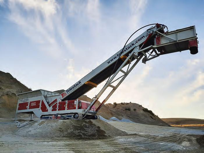
The OPS Group has access to Telestack’s complete range of equipment.
ensure each part performs properly.
The positive impact of Telestack’s equipment has already been felt by one of Burke’s clients, who recently acquired their first Telestack stacker. The stacker eliminated the need for manual labour and enhanced site organisation and safety. Previously, the client had to relocate their screening plant multiple times a day, but with the stacker, they were able to maintain a fixed position, resulting in improved efficiency.
The OPS Group has access to Telestack’s complete range of equipment, enabling it to cater to a wide spectrum of project requirements. Whether it is a small-scale job with a throughput of only 50 tonnes per hour or a massive undertaking necessitating throughputs in the thousands of tonnes, it is equipped to provide the appropriate stackers for the task at hand.
Burke said the bulk handlers also values flexibility and speed – and that is something the OPS Group can provide.
arises with immediate urgency. Bearing this in mind, we maintain substantial inventory distributed among multiple branches nationwide,” he said.
“At any given time, we have the capacity to service the majority of enquiries within a few days.”


The OPS Group has a footprint in QLD, VIC, SA, WA and the NT, as well as Indonesia. From these branches, the
Burke acknowledged that the industries served by the company generally operate continuously, prompting him to always guarantee accessibility to his clients.


“A simple phone call is usually sufficient to address any challenges our customers may encounter. We are committed to providing solutions and assisting them effectively,” he said.
Bulk solids storage and handling solutions generated in Australia for Australian Conditions

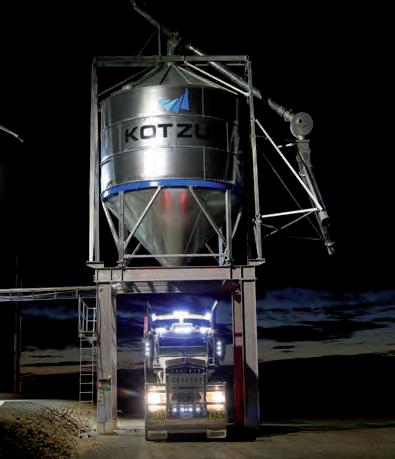

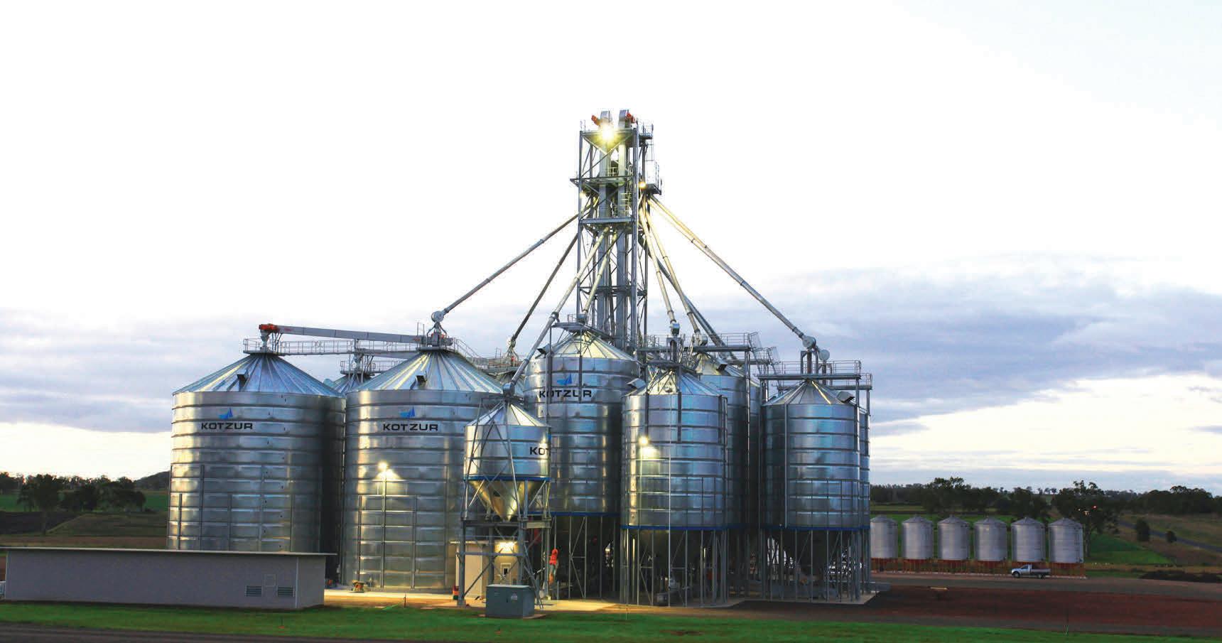
Walla Walla, NSW Toowoomba, QLD Perth, WA (07)4634 4622 info@kotzur.com www.kotzur.com (02)6029 4700 0475 294 701
The OPS Group provides specialist processing equipment and portable solutions.
ESS Engineering makes an impact with the cradle

The conveyor belt is the most crucial component in efficient bulk materials movement and the single most expensive component in the conveyor belt system.
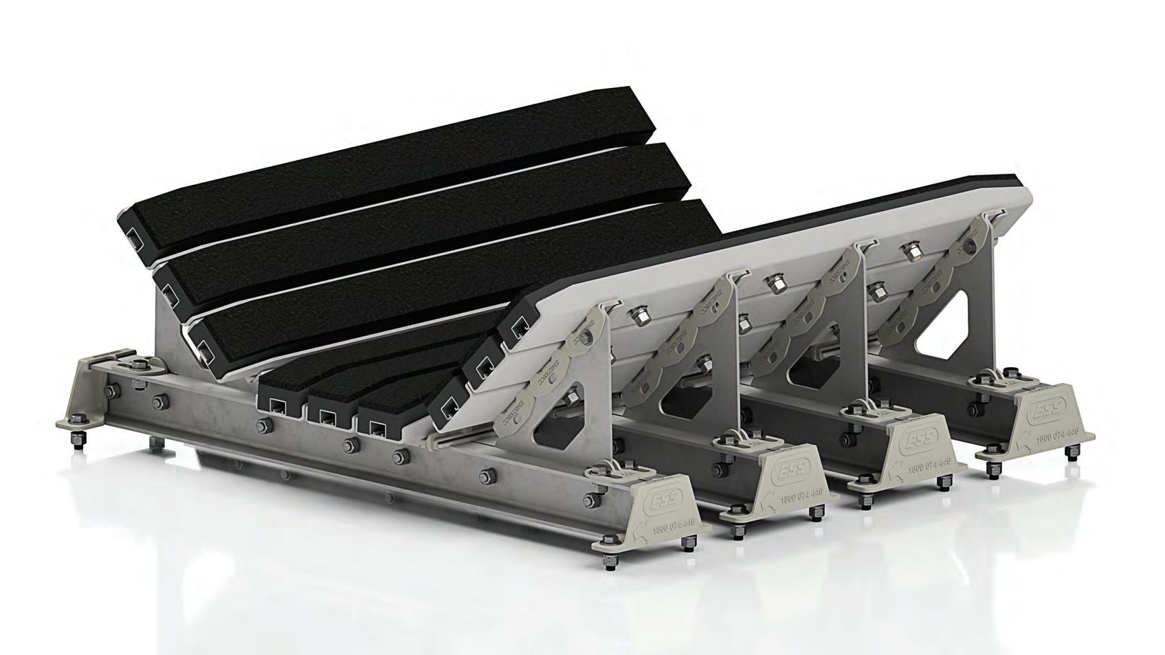
DAMAGE TO THE CONVEYOR BELT shortens its life and cuts into profits. While all conveyor belts will wear out over time, damage should be avoided where possible to ensure a reasonable return on investment. Bulk solids impacting the conveyor can cause accelerated damage to the idlers, structure and belt.
An impact bed is located underneath the belt at the impact zone, and it is designed to support the belt and helps absorb the impact of falling material. Impact beds also decrease the tendency of sharp edges of material piercing the belt.
These cradles usually comprise a set of individual impact-absorbing bars assembled into a steel support framework. The bars are made of durable elastomeric materials that combine a slick top surface, allowing the belt to skim over it, and sponge-like secondary layers to absorb the impact energy.
ESS has a long history of designing, manufacturing, installing, and maintaining ESS GAB Impact Cradles. However, the custom nature of these impact beds has meant that the price point was prohibitive to smaller operations and was generally supplied to heavy-duty applications where they saw the best return on investment for clients.
ESS now has a modular design for light-duty and medium-duty applications to make impact beds available to the broader market.
ESS research and development engineer Alex Adl said that the new impact cradle design would be close to 40 per cent cheaper than the previous module because the design was less labour-intensive and easier to produce.
ESS aimed to streamline the design process by creating a calculator that uses variables including material size,
belt speed, belt width and drop height to determine whether the application needs a medium or light-duty impact cradle.
The company focused on making a design suitable for a wide variety of medium and light-duty applications and reduced production time.
“The result was a design that uses independent modular support frames rather than interconnected and welded support frames to house the impact bars,” Adl said.
The modular impact beds are manufactured to provide consistent design and quality while ensuring a reduced lead time.
Adl said there are also on-site benefits to this module design.
“Scheduled downtime is common across all industries but none more so than those which consistently handle high degrees of bulk material,” he said.
MACHINERY 30 І Australian Bulk Handling Review: July/August 2023
The new modular bed is designed for light and medium-duty applications for the broader market.
“While inspection and preventative maintenance is always the best practice, many situations can leave companies
caught in reactive situations due to unexpected breakdowns in machinery.”
Load zones and transfer points are areas of high impact and throughput critical to the bulk material handling
is suitable for heavy-duty applications) but can be labour-intensive and costly to repair. ESS’ modular design for medium and light-duty applications means that downtime is reduced as only the parts that need to be repaired need to be removed.


Adl said that the modular design’s ease would allow on-site repairs and faster turnarounds for less downtime.
“If something happens on-site, you can just change the module rather than sending it all away (for repairs),” Adl said.
“You can just undo the bolt, replace (the module), and it is done.”
process. If these areas break down unexpectedly, the entire operation grinds to a halt. Therefore, it is essential to minimise downtime without sacrificing safety or quality.
Impact beds are in load zones, and the impact bars or frames inevitably need to be replaced because of the high impact. Traditionally, impact cradles are bolted together, which is beneficial for the product’s overall strength (which
This can constitute a significant cost reduction because only damaged modules must be replaced rather than the entire impact bed. This modular design also means that the impact bed can change with the application by adding and subtracting modules based on a site’s needs.
“You can add or change [the number of modules] depending on what you need, and most importantly, it can be changed on-site,” Adl said.
“While inspection and preventative maintenance is always the best practice, many situations can leave companies caught in reactive situations due to unexpected breakdowns in machinery.”
Here to help
Oli Vibrators has started expanding rapidly in NSW. ABHR sat down with the company’s sales manager responsible for growing the new market.
WHEN YOU NEED IT, where you need it. This strategy has led Italy-based Oli Vibrators to expand across the world, setting up dozens of trading subsidiaries – including in Australia.
The branch, located in the eastern suburbs of Melbourne, supplies a range of vibrators and flow aids for all manner of industries.
Oli is looking to grow. Costa Pegios has been tasked with establishing the company in New South Wales. With more than three years in the industry and extensive experience with the construction sector, Pegios said he is excited about the task.

“With the size of NSW and the amount of manufacturing that goes on in the state, it’s extremely important to have a presence here,” he told ABHR
“We’ve typically focused our time in Victoria. There’s a lot of potential here to make a real impact.”
Initially, Pegios met with existing clients in the region, along with his own contacts, letting them know Oli Vibrators is ready to help solve any flow problems they may be facing.
In many cases, the staff running a production line won’t have the in-depth knowledge and engineering skills to find the right solution. That’s why education has become an important first step.
One of the most common problems
Pegios found is hammer rash on the bases
of bins and hoppers. When flow stops or slows, one of the simplest solutions is to strike the equipment with a large hammer. This can get the material flowing again, but it comes at a serious cost. Constantly hitting expensive assets with a hammer causes damage to the system, leaving dents that can cause even worse hangups. In extreme cases, hammer rash can lead to catastrophic failure and puts workers at serious risks.
“I once had a customer that was coating popcorn kernels with salt. The problem was the salt came out of the bags in bricks. They had someone sitting at the base of hopper, smacking it with a mallet,” he said.
“A vibrator or flow aid saves people from thousands of dollars in terms of damaged assets, not including downtime for repairs.
“After installing our devices, the customer said they wanted to frame the hammer and never use it again.”
Pegios visits his client’s plants to spot the tell-tale signs of flow issues. If there are any, he discusses strategies with the customer before helping find a solution.
arise, and the ways to fix it. Quite often, the importance of flow aids isn’t front of mind for the company’s customers, which is why having a fresh pair of eyes on site is so important.
Pegios aims to establish an office and warehouse in Sydney. He is currently supported by the team in Melbourne, which have dozens of years in combined experience.

“Our general manager, Mark Thompson, is only a phone call away and has amazing knowledge about the industry,” he said.
“The journey in NSW has just begun. It’s been great to meet with our customers and to let them know we’re here to help.”
VIBRATORS 32 І Australian Bulk Handling Review: July/August 2023
A’SIA P TY LTD TRANSMISSIONS TORQUE ALL
Costa Pegios has been tasked with growing OLI in NSW.
Oli Vibrators supplies a range of vibrators and flow aids from Melbourne.

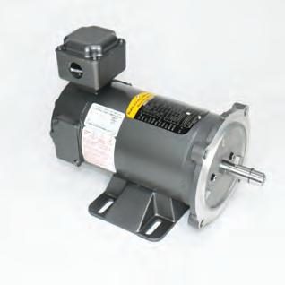
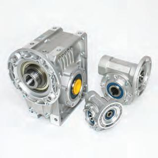
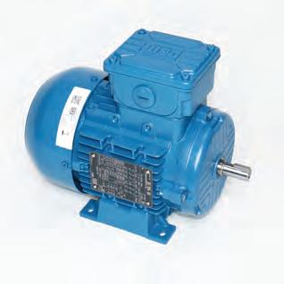


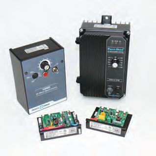
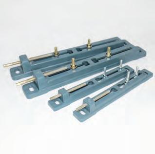
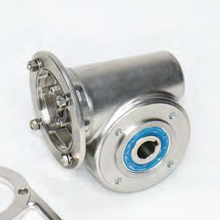
Servicing Australia Wide Contact us now for all your PT equipment requirements Bonfiglioli W, VF, C-A-F-S & Planetary gearboxes. VIC HEAD OFFICE 1/11-13 Lakewood Blvd, Braeside 3195. 03 9587 2212 sales@alltorque.com.au Large range of Flender N-Eupex, N-Bipex & Zapex couplings. Full
of Weg W21, W22, Mining Motors & inverters. Motor
80
Comintec Torque Limiters, roller & friction type. Dertec
gearboxes & motors for the food industry. Baldor DC & AC NEMA motors. KB Controllers for all DC & AC motors.Telcomec clutches & brakes. See the full range at www.alltorque.com.au VIC 6 Reserve Street, Preston 3072 03 9480 1566 preston@alltorque.com.au NSW 6/155 Glendenning Road, Glendenning 2761 02 9099 1149 nswsales@alltorque.com.au QLD 125 Balham Road, Rocklea 4106 07 3274 2677 sales@eta.com.au Power Transmission Specialists A’SIA P TY LTD TRANSMISSIONS TORQUE ALL
range
slide rails from frame size
to 355 in stock.
stainless steel
Tecweigh’s local touch
The Australian manufacturer’s latest conveyer belt scales are designed for weighing in the quarry, mining, and food industries in all conditions.
IN AN INDUSTRY that needs tailored solutions and quick turnarounds, Tecweigh’s Australian advantage has shone through for the customers in the bulk handling sector.
The Australian manufacturer has been producing a range of conveyor belt scales, weigh belt feeders and volumetric feeders for two decades from its Melbourne headquarters.
Being an Australian-made brand ensures Tecweigh’s custom-engineered products can perform dynamic measuring in the harshest of conditions.
Barry Gamble, Tecweigh’s business development manager, said being a local manufacturer has allowed the company to keep costs down and ensure continued supply.
“We do all our manufacturing in Carrum Downs, Melbourne, which gives us a fast response time,” he said.
“We can normally deliver what the client needs within seven to 10 days.”
Dynamic measuring is a key component in the quarrying, mining, food, and extractive industry which helps relay accurate information to customers.
Without accurate information, storage management and feed metering become incredibly difficult.
To ensure its products are reliable in Australia’s often-harsh conditions and provide accurate information, Tecweigh uses stainless steel, hermetically sealed IP68 load cells designed to provide accuracies of ± 0.5 or ± 0.25 per cent for its weigh belt feeders and conveyer belt scales.
The weigh idler system has been designed to be easy to calibrate to provide consistent accuracy. Its volumetric feeders have a range of up to 32,000 litres per hour with single or dual drives for loss in weight applications.
Its weigh belt feeders can also be manufactured to specific lengths and widths, using powdercoated mild steel or stainless steel, depending on the application.
“Custom designs are our standard. Whether it is chemicals, crushed stone, sand, coal, or materials that are low density, sticky, or abrasive, we specialise in building the equipment needed to accurately weigh it,” Gamble said.
“Our products are also designed for heavy-duty work and have been proven over time to be accurate in some of the world’s harshest environments.”
With more than 100 years of industry experience collectively among its
employees, the company is continuing to look for new innovations.
Gamble said that in addition to its main range of products, the company is increasing its range with a new loss in weight controller.
“It uses an Australian-designed and built signal conditioner circuit board, deployed at the heart of Tecweigh’s measuring and metering products,” he said.
“The loss in weight controller gives users greater accuracy for dispensing products and provides an extra layer of control over an ordinary volumetric feeder by using feedback from a scale.”
The fact it is based in Australia means Tecweigh can also offer local after-sales support. The company maintains a significant stock inventory for its conveyor belt scales, volumetric feeders, and weigh belt feeders. It also offers field service support and spare parts supply.
From humble beginnings, Tecweigh has built its bespoke business to provide weighing-in-motion solutions for industries nationally and Internationally.
The company has built a long-lasting relationship with its own local suppliers and aims to further grow in the industry.
AUSTRALIAN MADE 34 І Australian Bulk Handling Review: July/August 2023
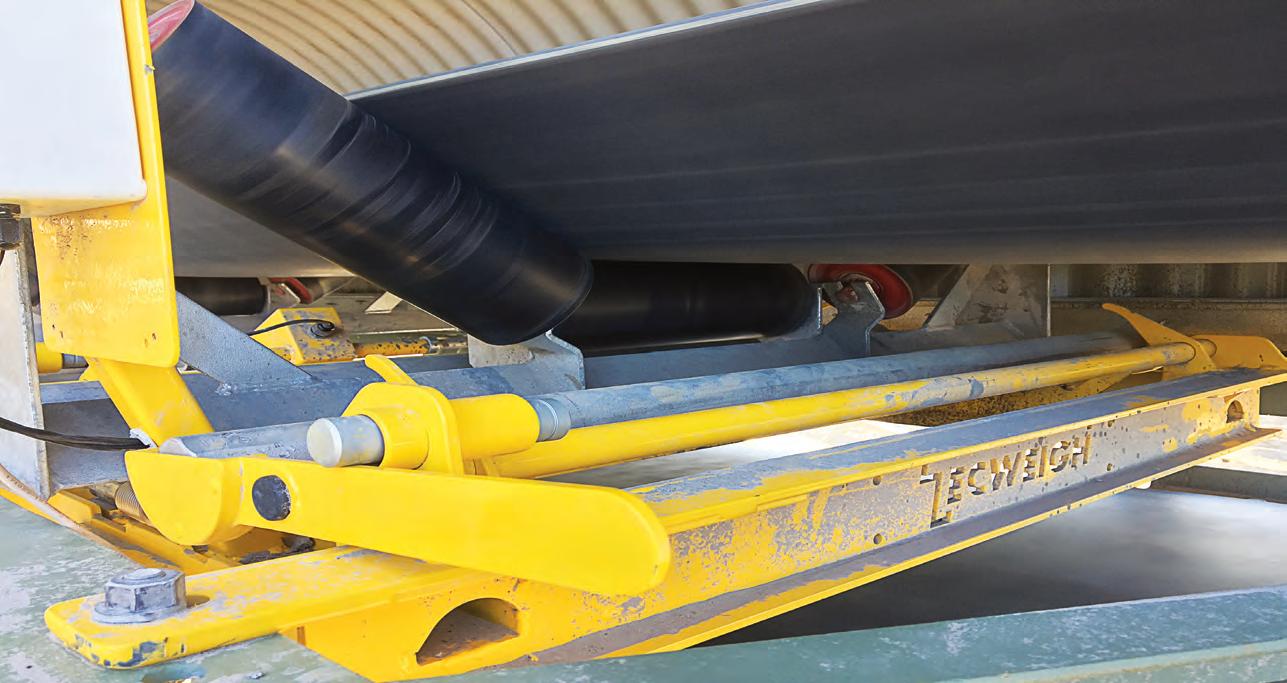
Conveyer belt scales are designed for weighing in the quarry, mining, and food industries in all conditions.
Do you talk conveyor belts? Talk to us!
We are looking for people importing, using, recycling, and disposing of conveyor belts to join a working group to shape a better future for used conveyor belts.
Conveyor belts are highly specialised equipment, made using quality materials and technology. At the end of a conveyor belt’s life, they often end up in landfill or stockpiled onsite. It’s not without reason – we know there are barriers to recovering conveyor belts.

Tyre Stewardship Australia is on a mission to find better uses for end-of-life conveyors. And we need your knowledge and conveyor belt know-how to make it happen.
Express you interest to join our conveyor and rubber tracks working group
Email us your name, company, position, and experience with conveyor belts and rubber tracks, and why you want to join the conveyor belt and rubber track working group to getonboard@tyrestewardship.org.au by 30th August 2023.
Packed for success
ABHR sat down with a co-founder of bulk bagging manufacturer Packweigh to learn how the company has grown.
ROD WILSON and his business partner Jim Nolan had found a gap in the Australian market.
The pair decided to take the plunge, launching a small business that supplied industrial sewing machines for bagging equipment.
Now, almost 20 years later, Packweigh Equipment has expanded its customer base, product range and physical size, becoming a major manufacturer of packaging equipment.
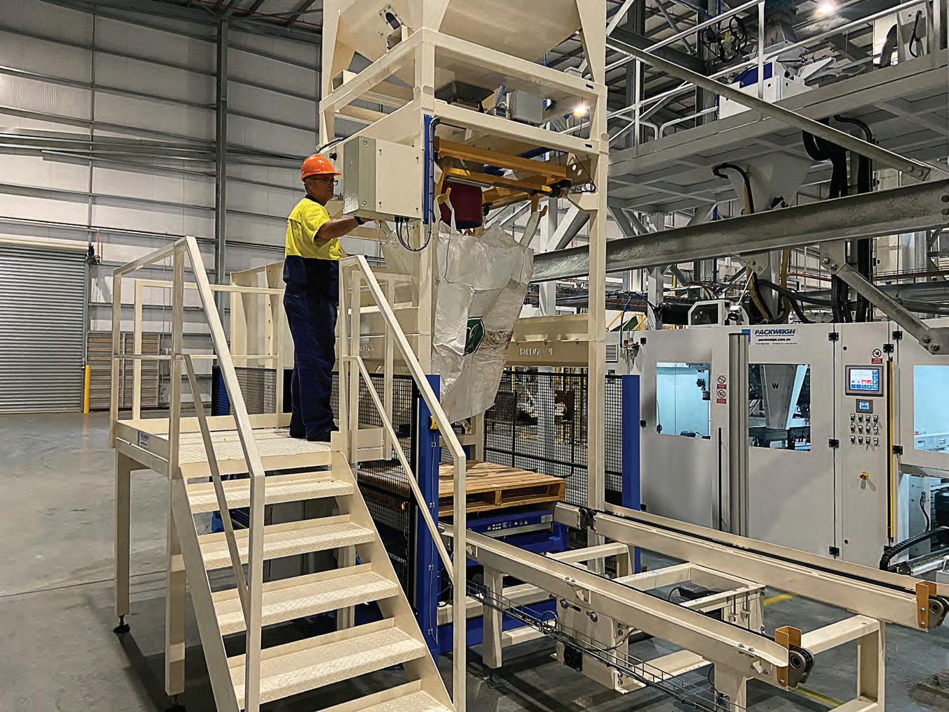
While the company originally focused on industrial sewing machines, it has since branched out to include weighing equipment, conveyors, and palletising systems.
Nolan worked as the company’s lead designer, coming up with many of the machines in the company’s product line,
while Wilson helped grow the businesses through sales and customer relationships.
A major motivator for the pair was quality. They had seen equipment in the industry that wasn’t up to their high standards. In fact, manufacturing reliable and long-lasting equipment is a core part of the company’s mission.
Wilson told ABHR that being the manufacturer means the company is more accountable for the quality of its products.
“When you rely on other stakeholders, there’s a chance there you can be let down. We didn’t want to let our customers down – so that meant having as much control over the manufacturing process as possible,” he said.
“Our equipment isn’t just being assembled in Australia – we use Australian suppliers wherever possible,

designing the machines to use locally obtainable parts.
“This means that if we ever don’t have something in stock, we can quickly get it from our supplier, minimising delays and downtime.”
The company aims to be a longterm business partner for its customers, which is why it works alongside them to find the equipment that is suited to their needs and budget.
Wilson said this customer service is what has led to Packweigh’s success.
“We spend time with our customers, give them all the options up front, explain what everything does and don’t take anything for granted,” he said.
“We discuss their needs and do all the layout, drawings, and planning to make sure they get the right tools for the job.”
AUSTRALIAN MADE 36 І Australian Bulk Handling Review: July/August 2023
The company manufactures and ships its products from its Brisbane-based factory.
“Everybody’s different, which is why we design to suit the customer’s needs.”
The process usually involves determining what the customer wants out of the packaging equipment. Wilson will then help design a potential solution that is iterated upon before being implemented.
Feedback from clients has been
positive, with some doubling their output with half of their staff, leading to returns on investment in as short as six months.
The company manufactures and ships its products from its Brisbanebased factory. There, it has the space to assemble full bagging lines and customers can even visit to see the equipment in operation.


The company moved two years ago to accommodate Packweigh’s growth.
“We’re building bigger machines now and can take advantage of the larger space,” Wilson said.

“It’s led us to gaining more market share, which has led to even more growth. We’re looking forward to continue expanding and supporting the Australian market.”
TheLeaderinBeltScale InnovationSince1964
ThayerScalehasmanufacturedhighaccuracyandcertified-for-trade beltscalesforover50years.Many,ifnotmostofthefeaturesinmost current-generationbeltscaledesignswereoriginallyintroducedby ThayerScale.Wecontinuetoleadthewayininnovationandexcellence.
TolearnhowThayerScaleachievesbetterthan+-0.1%accuracyon eventhemostextremebeltscaleapplications,contactustoday.

Thayerscale.com +1781.826.8101
Packweigh can assemble full bagging lines.
Finding new markets
SINCE INCEPTION IN 1987, Transmin has become a major player in bulk handling equipment for the mining and minerals processing sectors in Australia and overseas. The company has experienced significant growth in the last few years. To maintain that growth, several strategies are being implemented which include structural change, product development, innovation, supply chain growth and team building.
One of the products which has benefited greatly from recent changes is Transmin’s reagent plants, which play a core role in mineral processing. Reagents such as lime, flocculant, soda ash, guar, and other materials are used within mineral processing activities to control pH, clarify solutions or aid in the chemical reactions taking place during mineral extraction.
Reagent plants have always played a core role at the Western Australian manufacturer. In fact, reagent plants are where everything started for the company, when it commenced business supplying reagent preparation plants to the WA gold mining industry.

Phil Gilbert, director of capital sales and business development at Transmin, has been with the company for twenty years and has seen reagent plant business grow substantially alongside the mining industry. Other parts of the business including feeders, rockbreakers, bin isolation gates and grinding media handling systems also grew rapidly, especially during several mining booms.

He told ABHR that Transmin had grown significantly in the iron ore and hard rock sectors and is looking to grow further in other expanding industries both in Australia and overseas.
“For example, due to the growth in demand worldwide for battery technology, there’s a huge amount of activity in the rare earth minerals and lithium at the moment,” he said.
“A few years ago, most of our business was supporting the iron ore industry with feeders, rock breakers and gates. While we’re still very active in these areas, we’ve seen a major upsurge in the reagent side of the business.
“Since the start of the 2022 financial year, we’ve secured about 12 reagent projects for sectors such as lithium, water treatment, rare earth and gold, some of which are of a substantial size.”
To strengthen its offering and ability to deliver projects more effectively, Transmin has changed its structure to three ‘product vertical’ streams each focusing entirely upon a specific range .
Historically, equipment for the iron ore industry needs to be heavy duty to handle the intense loads and operating conditions they are exposed to. For other industries and mining sectors, Transmin has developed the design of its equipment to better suit the different materials and the conditions they will face.
For example, the company has designed a new range of feeders for the tailings reclamation projects.
It has also grown the capability of its team, training its staff to be experts on
their product lines. By turning its staff into specialists, Transmin can offer more detailed expertise.
Gilbert said that sourcing of new employees and employee retention can be a challenge at the moment.
“Mining companies and suppliers are all competing for the best talent in what is a fairly limited market, especially in Australia, we are all fishing in the same pool in terms of employees,” he said. “That can make things tricky as there is a shortage of qualified and experienced people.”
“We’ve had to be creative with our policies of employee engagement and retention which is working well.”
Transmin’s specialists work closely with its customers to determine what will work best for the specific project. Often, the company’s customers are looking
PROCESSING 38 І Australian Bulk Handling Review: July/August 2023
Phil Gilbert and his team are responsible for developing new business opportunities for capital equipment sales at bulk materials handling equipment specialist Transmin. He tells ABHR about the latest markets the company is targeting.
Phil Gilbert, director of capital sales and business development at Transmin.
Transmin has developed the design of its equipment to better suit the different materials and conditions they will face.
for a complete system instead of one put together from a variety of sources.
“Our customers are facing global uncertainties and the market is changing, which could have major flow on effects. Our structure and operational capability means we can quickly respond to change and ensure nothing is overlooked,” he said.
When it comes to delivering projects, Transmin has invested heavily in its design, manufacturing, and supply chain management systems to make it more competitive. It has multiple sources of fabrication and has signed agreements with components suppliers to ensure the continuity of supply and customer support.

Transmin also aims to grow further into new markets overseas, following considerable recent growth. Gilbert said the local market is not large enough to sustain Transmin’s potential growth.
The company already has a presence in North America, South America, India, and Africa and is investigating further opportunities to develop those markets, be it via potential acquisitions, local offices or business partnerships.
Gilbert said the challenge regarding expansion overseas is complex and includes such factors as defining your point of difference plus overcoming the fact that the market doesn’t know who you are.
“We’re a household name in WA, but as you start selling in other countries, you need to offer a compelling value proposition compared to the existing local incumbents, and the ability to support your customers after the sale” he said.
“We have been very successful with our low profile feeders overseas because the technology offers a significant point of difference compared to conventional feeder technologies. They’re a much more space efficient installation when compared with traditional feeders, we can go a lot wider and longer than other feeders, and change direction to elevate the discharge point which saves transfer excavations.
“This versatility has allowed us to be successful with multiple installations in North America, South America and Africa in the last couple of years.”
Transmin developed the low profile feeder technology more than 15 years ago.

Australian Bulk Handling Review: July/August 2023 І 39
skirts, wear liners, belt scrapers/cleaners, motors, and gearboxes.
dry tailings stacking, rare earths, gold, copper,” he said.
Reagent plants have always played a core role at Transmin.
Time for conveyor belts to be part of Australia’s circular economy
Conveyor belts are typically destined for the scrap heap. Australia’s tyre stewards want to find ways to turn used conveyor belts into new products.

TYRE STEWARDSHIP AUSTRALIA
(TSA) wants to change how the bulk handling industry thinks about, plans for and manages conveyor belts once they reach the end of their life.
Many companies have limited incentives to recycle their waste into value-added products, which increases landfill and on-site waste. Conveyor belts come with a unique set of safe handling and recycling challenges that make recovery that much harder.

An estimated 60,000 to 85,000 tonnes of waste conveyor belts are generated each year across Australia, with less than 1 per cent of conveyor belts being recycled - the majority are stockpiled, buried onsite at mines, or sent to landfill.
It’s no surprise to anyone in the industry that conveyor belts are not being recycled. Their length, structure and weight mean they often can’t be handled by existing equipment on site, and their composition can be embedded with steel cords and fibres that can damage standard recycling equipment built for tyres.
The Australian Government has sent a strong message to the market– It’s time to get serious about a circular economy for Australia’s rubber products. Environment and Water Minister Tanya Plibersek added tyre products to the waste priority lists in October 2022, emphasising that if the industry doesn’t act the government will.
Just recently the WA Government has been selected to develop the framework to guide inter-jurisdiction efforts and take action on problematic products like off the road (OTR) products. TSA will support the WA Government to develop the framework.
Tyre Stewardship Australia wants to work with the bulk handling industry to find out how worn-out conveyor belts can contribute to Australia’s circular economy.
TSA CEO Lina Goodman is positive that by working together with the conveyor belt sector, solutions can be found to recover the valuable resources in used conveyor belts.
“There’s so much we can achieve by bringing together conveyor belt management and disposal knowledge from people who deal with it every day, and our experience in rubber recycling in Australia,” she said.
“We are establishing a working group with experts in conveyor belt manufacturing, importing, handling and disposal to create and test ways to get conveyor belts recycled, and
CONVEYORS
TSA hopes more bulk-handling companies will join in its efforts to advance Australia’s circular economy.
Conveyor belts, can be re-manufactured into high-performing infrastructure and construction materials.
are looking for conveyor belt boffins to come and join us.”
Goodman believes Australia risks being left behind if industries, like bulk handling, don’t go all in, on recycling.
“We’re now looking at a huge opportunity to step up and become the world leaders in recovering and recycling off-the-road rubber products, including mining and agriculture tyres and conveyor belts, ” Goodman said.
“Many countries are already moving into this market, and if we sit on our hands now, we will be left behind.”
Goodman said landfill or on-site burial could no longer be considered reasonable options for used conveyor belts.
“Times have changed, and what we did in the past is no longer good enough. ”
Used rubber products, like conveyor belts, can be re-manufactured into high-performing infrastructure and construction materials with innovations like crumb rubber asphalt, and permeable pavement, as well as Australian innovations like blast and
ballistic concrete. The addition of rubber materials provides numerous benefits including flexibility, durability, and reduced carbon
More products are coming to market which use rubberised elements to improve products, which Tyre Stewardship Australia hopes to increase going forward.
A recent crash test at Lardner Park in Victoria showcased how rubberised concrete barriers (made with rubber from used tyres), can add economic and performance value to traditional products. The crash test showed the Rubber T-Lok barriers improved performance by decreasing impact severity and other safety benefits, and economic value by increasing the life span compared to traditional concrete barriers.
Goodman said further innovations needed to be encouraged by multiple partners across industry, government, and business.
Tyre Stewardship Australia hopes more bulk-handling companies will join in its efforts to advance Australia’s
promote the recovery of OTR products at the end of their life.
Goodman said with collaboration and commitment, recycling conveyor belts could become a reality.
“There is no quick fix, but now is the time to step up, take action and stop throwing away the valuable resources in used conveyor belts”.
CELEBRATING 30 YEARS OF SCALE MODELLING
At BSM we have been conducting physical scale modelling of transfer chutes globally for 30 years.
At our dedicated facility, we can construct a scale model in laser cut acrylic and test its performance using our state-of-the-art equipment with fully computerised logging of all key parameters, including throughput, in real time.
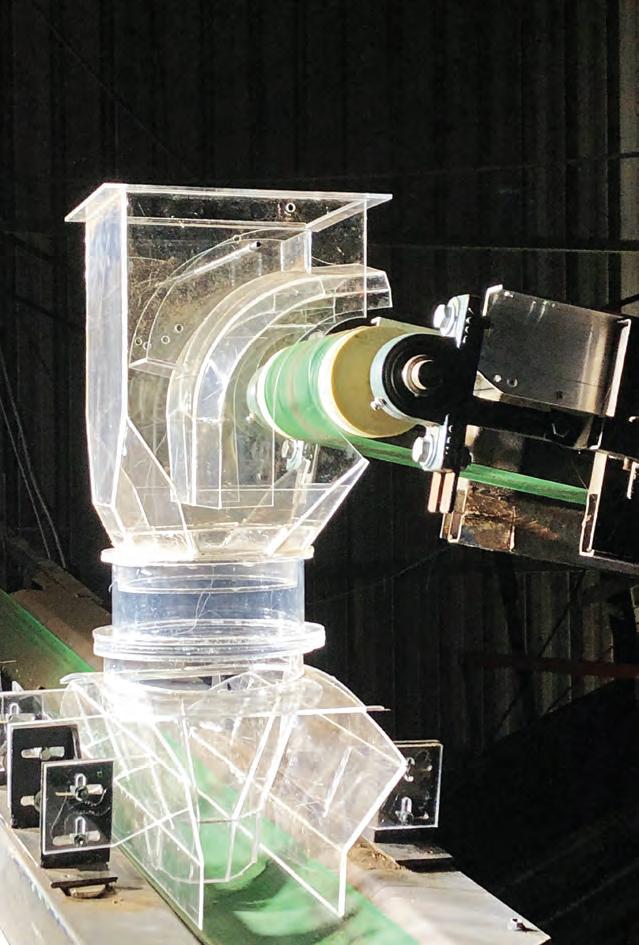
We offer independent consulting and complete confidentiality.
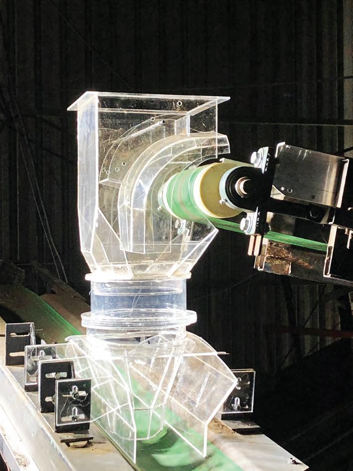
Email: Peter@bulksolidsmodelling.com.au Phone: +61 8 488 061 407 Web: www.bulksolidsmodelling.com.au 91 Ilmenite Crescent, Capel, Western Australia 6271
you considering a new conveyor transfer chute design? Need an independent validation check?
Are
in touch today to
Get
discuss your project.
Lina Goodman is the CEO of Tyre Stewardship Australia
How low can Thor go?
Thor Global says its latest low-profile telescopic radial stacker has the lowest feed height in the industry. ABHR learns what this will mean for bulk handlers.
IN 1992, Thor Global developed one of the first-ever telescopic conveyors for bulk material stockpiles. The machine was designed to help meet increasingly stringent requirements for supplying in-spec aggregate material.
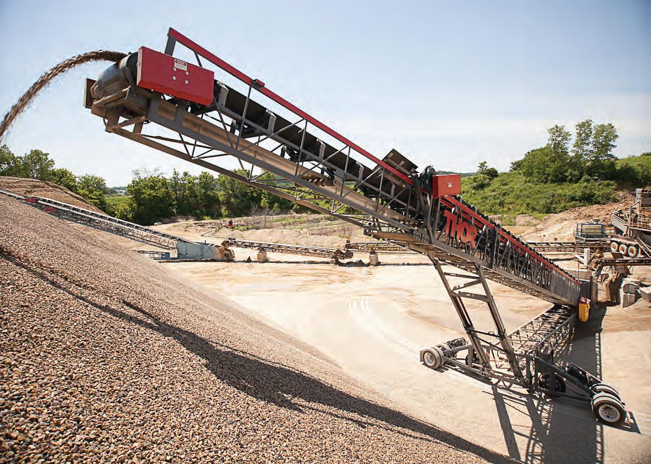
Armed with the new equipment, operators could now build stockpiles in small concentric layers, ultimately reducing segregation.
And it proved to be popular.
In fact, demand for the product was so intense that Thor decided to shift its primary focus towards developing and improving the telescoping conveyors.
The company has now unveiled its latest telescopic radial conveyor, which the Lincom Group aims to spread across Australia.
Alan Dunbar, Lincom Group product manager, said the Thor Lopro’s patented low-profile design has the lowest feed height in the industry while maintaining a
large truss for strength and stability.
“The Lopro has a feed height of 1.7m and can handle up to 1000 tonnes per hour,” Dunbar told ABHR. “The lowprofile design allows the feed angle to remain constant, improving versatility and eliminating the need for additional conveying equipment.
“You can park a crusher right next to it and feed directly into it without needing an extra conveyor. The conveyor’s low height also makes it easy to transport.”
Canada-based Thor designed the machinery to meet global standards. The Lincom Group is the company’s registered Australian distributor and has ensured the machine meets local standards.
The control system has been built for Australian conditions. It features a dual split panel with high- and low-voltage sides independent of each other to help manage heat dissipation.
It comes with an HDMI touch screen and remote control as standard, along with a full suite of sensors. Safety measures and guarding also meet Australian requirements.
Dunbar said Lincom can design the stackers to suit the customer.
“The big one for most quarries and coal mines is making sure the new equipment fits the site,” he said. “These companies have their own standards and may require redesigns to ensure a conveyor meets them.
“Standards also differ based on state – Western Australia and New South Wales have different requirements. We go through a full design with customers that need them, providing detailed drawings and support.”
All of Thor’s equipment is engineered for heavy industry, designed to last in extreme conditions, using high-quality steel, paint and components. Everything is made to operate for a minimum of 80,000 hours and meet Thor’s quality minimums.
Dunbar said Lincom is excited to bring the Lopro to Australian shores.
“We have service teams in every state and a large spare parts holding for our conveyors,” he said.
“We are also working on a fully certified design for the Lopro, making it even easier to provide for our local customers.”
CONVEYORS 42 І Australian Bulk Handling Review: July/August 2023
Lincom can design the stackers to suit the customer.

www.vayeron.com info@vayeron.com.au Phone: 1800 404 160 Follow us Belt stoppages Belt & Idler fires Bulk change-outs Too hard to inspect “Never worry about your conveyor idlers again!” Train Loadouts I Shuttles I Ship Loaders I Bucket Wheel Reclaimers I Conveyors in tunnels I Conveyors up high Reduce your operational risk profile Improve maintenance Use your phone camera to scan the QR code
Tough troughs
ABHR spoke with Rod Howell to learn how Allied Grain Systems is using its range of custom designed belt trough conveyors.

DELIVERING COMMERCIAL-SCALE grain handling projects is a complex task, and it’s one that Allied Grain Systems doesn’t shy away from.
It has almost 30 years of experience engineering and overseeing the construction of these projects.
Conveyors often play a key part in these projects, and are responsible for handling the storage, delivery, and movement of grain.
Rod Howell, a project engineer at Allied Grain Systems, told ABHR that this is why the company offers its own belt conveyors to incorporate into the company’s projects.

number of years – since the busines started,”
of that. It shortens delivery times because we know exactly what we need. Anything we source internationally is done on a
customise the conveyors for the customer.

CONVEYORS
Allied Grain Systems has partnered with international manufacturers to provide specialised conveyors.
The trough conveyors are designed to be reliable.
The trough conveyors are designed to be reliable and continue running without issue for several years. The engineering team is conservative when it comes to designing equipment, using larger bearings and shafts to ensure the system is as reliable and durable as possible.
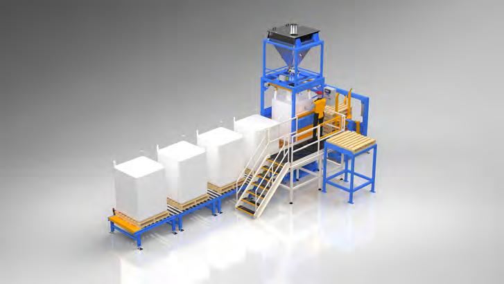
Howell said this is because the last thing a customer wants to deal with is equipment failure when unloading a train or moving product.
“A conveyor is only as strong as its weakest link,” he said.
“On the operational side of things, we provide guarding and covers for conveyors, along with emergency stop systems. We work closely with the electrical control systems to offer these to the customer.

“We’ve also simplified the design over the years, making it easier to maintain and require less maintenance. There’s a skirt system that can be adjusted, so if it begins to wear out, an operator can change it out quickly.”
The company’s manufacturing facility is in Young, NSW, with a second branch

 Packweigh Equipment is your trusted partner for advanced bagging solutions
Versatile manual or automatic bagging
info@packweigh.com.aupackweigh.com.au 21 Hook St, Capalaba 07 38231033
• All types of bag closures
Contact us today to discover how Packweigh Equipment can elevate your bagging efficiency and take your operations to the next level
Load securing by wrapping or hooding
Allied Grain Systems can build equipment to the exact requirements of a project.
Conveying without a belt
NetterVibration is providing bulk handlers with a conveyor that uses vibrators to move material.
WHEN YOU THINK ABOUT A conveyor, some of the first things that might come to mind are belts, gearboxes, and tracking.
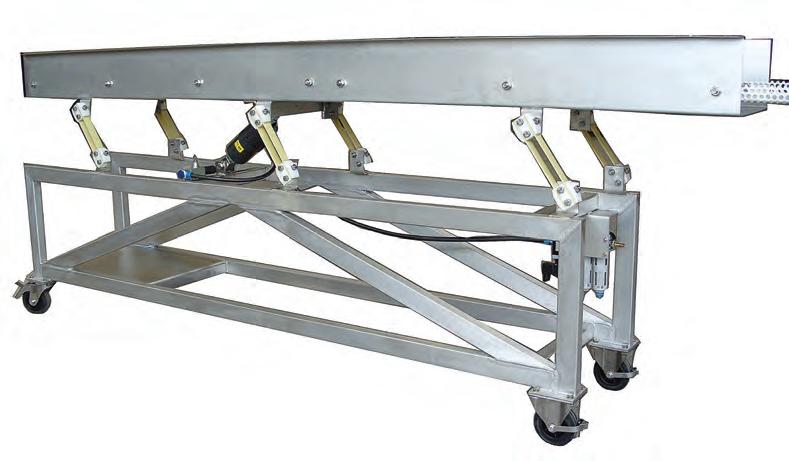
Resonance conveyors have none of these things. Instead, a single pneumatic vibrator with specially designed connections and blade springs operates at resonant frequency.
John Isherwood, managing director of NetterVibration Australia said the conveyors benefit from almost zero maintenance.
“NetterVibration resonance conveyors use a standard NTK model, with the size calculated on the weight of the tray and the product to be moved,”
“It just needs lubrication from a standard filter, regulator, or lubricator, as used with any pneumatic installation.
“The frequency is fixed to suit the resonant frequency of the blade springs. Adjustment of the exhaust air throttle will give adjustment of the stroke, and hence the conveying speed, while operating if necessary.”
NetteVibration FlexiLink connections between the tray, vibrator and the base ensures the conveyor tray follows a linear
Because the vibrator is mounted underneath the tray, there are no external moving parts, except the tray itself. This also means the tray is the largest part of the construction.
Speed of transport can be up to 40m/min, with capacity, depending on the product up to 50t/hour, with small inclines possible.
Isherwood said the company works closely with its customers to solve problems they are facing, using its wide range of vibrators to find innovative solutions.
“Our range includes electric, pneumatic and hydraulic vibrators, with force outputs from 14N to in excess of 170,000N. The vibrators are manufactured to extremely high quality in Europe, with ATEX rating as standard on most electric models, and rating 1 and 2 available to order on all models,” he said.
“NetterVibration has been manufacturing vibrators for almost 70 years, and you can rely on the European standards of quality,” he said.
“Over that time, the business has only focused on vibration and improving its products. It has developed specialist expertise and understands what works and what doesn’t.
NetterVibration Australia is the German company’s local branch, set up in 2019 after supporting the bulk handling industry through an import agent. It has seen significant growth during this time, setting up a warehouse in Mandurah, south of Perth, and more than doubling its turnover.
An important part of the process is learning about what exactly the customer is trying to achieve.
Isherwood said there is no one-size fits all vibrator, so he works to find the most efficient and economical model for a specific application.
“Whether it’s to help product move from hoppers or chutes, or to act as drives for vibrating feeders and compaction tables, we can help choose the right solution,” he said.

Isherwood said the company continues to grow in the Australia.
“We’re working close with clients to help them achieve optimum outcomes in their processes,” he said.
CONVEYORS
Resonance conveyors use a single pneumatic vibrator with specially designed connections and blade springs.
The vibrator is mounted underneath the tray so there are no external moving parts except the tray itself.
Syntechtron is an Australian owned company specialising in vibratory materials handling equipment designed and manufactured at our head office and workshop in Sydney NSW. Our comprehensive product range includes single and two-mass vibratory feeders, screens, conveyors, vibratory stockpile reclaimers, bin vibrators, specialised hopper outlets and flow gates for the mining, chemicals, pharmaceutical, food and beverage, and other industries.
For over 65 years the Syntron & Link-Belt range of equipment has been manufactured in Australia under the brands ICAL, Transfield Process Equipment, TPE Kintech and now Syntechtron Pty Ltd. The product drawings, service and test records, application knowledge and design expertise are all retained within the Syntechtron family.

Syntechtron’s Sydney design office and factory capabilities include application engineering design expertise, CAD, 3D modelling, FEA and drafting, manufacturing workshop assembly and testing, EEHA, machine diagnostics, technical sales, audit, commissioning and service and has available an extensive spare parts inventory.
Our equipment is designed and manufactured in Australia including the Syntron range which is manufactured under license to Syntron Material Handling.
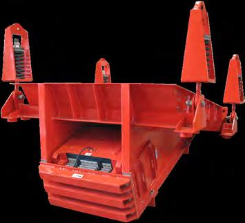
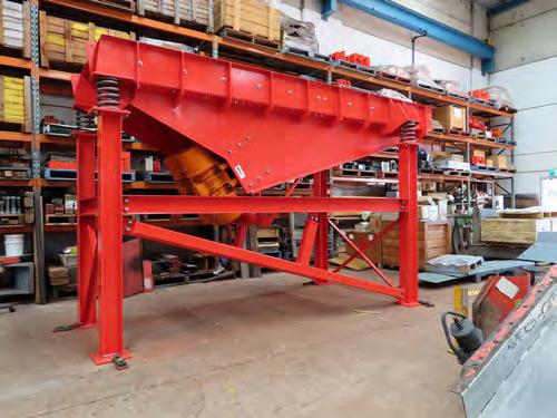
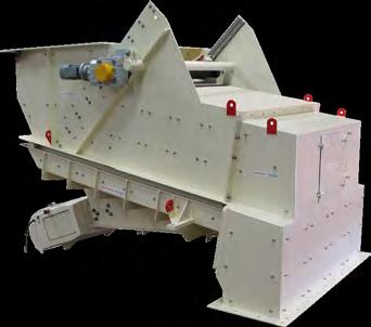

VIBRATORY SCREENS ELECTROMAGNETIC FEEDERS DEWATERING CONVEYORS www.syntechtron.com Sydney Head Office. Ph. +61 (0)2 9679 7022 17 Butterfield Street Blacktown NSW 2148 Syntechtron Pty Ltd Proudly Australian Owned
ELECTROMECHANICAL FEEDERS
Removing material from an operating conveyor belt
Thomas Greaves from DYNA Engineering explains the reasons to consider installing a diverter plough.
IF YOU’VE EVER WISHED you could remove all the material from your operating conveyor without having to waste time and money by shutting it down first, a diverter plough (DP) may be just what you’re looking for.
You might be wanting to start using your crushing plant to manufacture road base, or perhaps you have a need to remove contaminated or low-quality material from the belt before it reaches the storage bins, or possibly for removal of material in case of a breakdown, or a requirement to divert a certain amount into a ground bin.
There are many reasons to consider installing a DP, not the least of which is its relatively low cost and short production lead time.
How it works
Designed to fit onto an existing conveyor structure, DYNA Engineering’s DYNATrac diverter plough can be raised and lowered as required, allowing the normal operation of the conveyor to continue even when the DP is not in use. It can remain raised to allow material to travel under it when not in use.
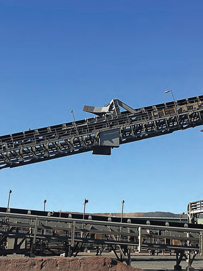
When activated, the DP blade will start to lower onto the belt while the belt support underneath lifts the belt from a trough shape to a flat shape. This enables the blade to lightly contact the belt across the entire width, ready to divert material off the belt surface.
Material then impacts the blade in a steady stream, and it will begin to push the material to one or both sides of the conveyor, into discharge chutes.
Design considerations
Blades are commonly made of hardened steel, engineered plastics or polyurethane. The composition of the blade is an important consideration as it needs to be wear-resistant enough to withstand
the application, but, at the same time, be subtle enough not to damage the conveyor belt.
The choice of blade is dictated by three factors:
• How fast the conveyor belt is running. How much material is being conveyed.
• Where the material is being moved to.
Double-sided blades can handle a higher material flow rate compared to a single-sided blade. However, they will usually incur added costs for additional chutes and structures.
Part of the DP design and engineering project incorporates a belt support system. This mechanism is constructed in a series of transition and flat idler rollers that shape the belt from a trough profile to a flat profile when engaged. A mechanical
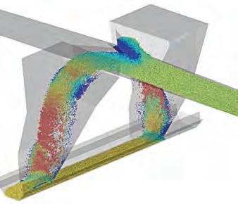
DIVERTER PLOUGHS 48 І Australian Bulk Handling Review: July/August 2023
DYNA Engineering designs, engineers and fabricates the diverter ploughs.
A diverter plough is an apparatus that can redirect or discharge the material being conveyed.
down to a suitable discharge location below the conveyor structure. Typical discharge locations include loading points on another conveyor, storage bins, stockpiles or a dump truck parked below the discharge chute.
Recent case study
DYNA Engineering installed a DYNATrac DP on an overland-conveyor system
in one of Western Australia’s largest iron ore mine sites in the Pilbara. The complete assembly was locally designed, engineered and fabricated in the company’s Bayswater (WA) workshop, requiring over 15 tonnes of locally sourced steel work to be utilised.
The DP was being used to divert material from the conveyor before it reached the head pulley, creating a
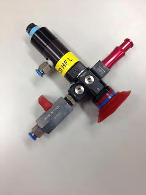
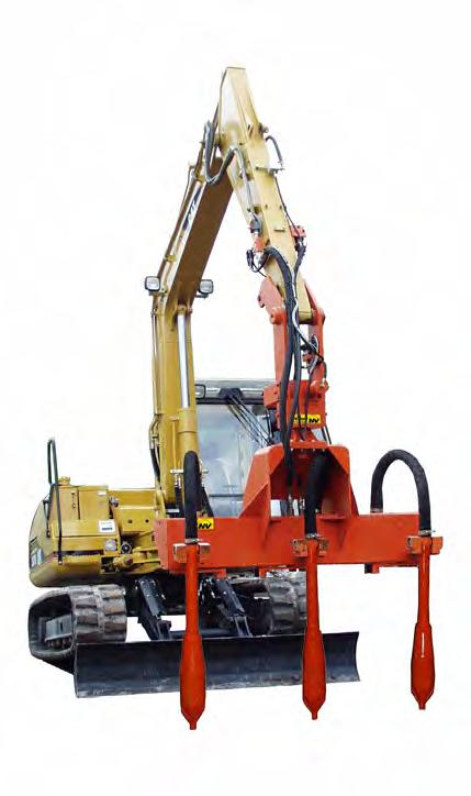
stockpile while the stacker conveyor was still under construction. This gave the operators the ability to commission the processing plant which was further upstream in the system.
To realise the project DYNA Engineering team worked closely with the client’s engineering team, designing and producing a detailed and customised solution able to meet all the customer’s needs, specifications and requirements.
Designed, engineered and fabricated in under 12 weeks, the double-sided V blade is able to push up to 4,500 tonnes per hour of iron ore fines from the 2000mm width belt into purpose designed chutes.
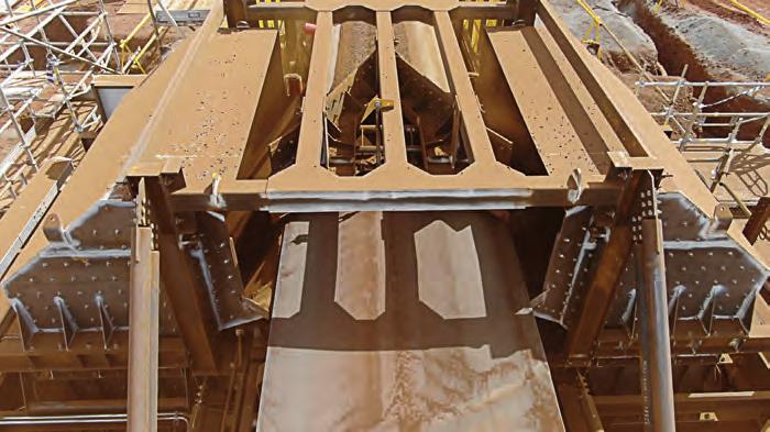
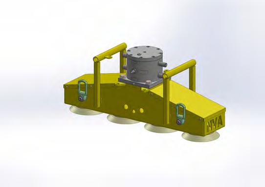
Typical DP applications
• Material flow alteration
• Material separation

• Bin maintenance and emptying of storage bins
• De-watering

From
to
product
and
All with German design and manufacturing quality. NetterVibration Australia Pty Ltd 08 9582 9531 2/19 Rafferty Rd Greenfields Western Australia 6210 Germany France Switzerland Spain Poland UK Australia www.nettervibration.com.au info@nettervibration.com.au
small
not so small, NetterVibration have the largest range of vibrators, electric, pneumatic and hydraulic, to handle any
flow
compaction issues.
A diverter plough in operation.
Analysing impact forces and overcoming issues in high-capacity belt support applications
Limitations to the parameters at which belt support failure occurs have been found experimentally in the past. Kinder Australia, however, aims to predict a specification limit for its belt support systems to ensure that it will survive and push the boundaries in terms of belt speed and capacity.
A FAILURE FROM INSUFFICIENT support is unheard of within Kinder Australia. All of its “impact” rated systems have fully supported rails. Only the K-Sure Support uses a slider surface that is not fully supported. This system is not considered for severe impact loading, only as a slider surface for 1000TPH maximum systems and lump up to 50mm.However, there is much to be learned of how a dynamic system can reduce impact loads in the pursuit of belt preservation.
A dynamic belt support system consisting of UHMWPE slider rails supported by steel plate had measurement devices fitted to analyse friction heating and impact loading.
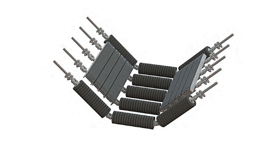
Temperature data showed a 7°C difference measured over 20mm (Figure 2, sensor 3), which was less than expected. Such friction heat losses may be attributed to convection from the sides of the slider rails, quite feasible given the slider width in the centre is made up of three segments, allowing for much surface area that can interact with some potentially turbulent air due to the moving conveyor belt.
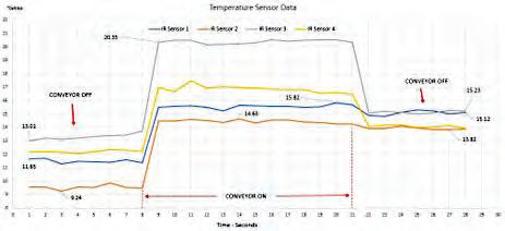
A superior slider material has been
observed in a Kinder installation since 2011. An increase in belt speed or capacity insists that it either use rollers in the centre (Combi system), use a slider material with better properties or a combination to reduce friction. This can also be necessary in slow moving feeder belt applications, where the pressure across the transfer is very high. To ensure there were no drive power issues or overheating of slider materials, Kinder used a centre roller and the K-Glideshield product at the wings as slider surfaces.
engineered plastic that has far superior mechanical and thermal properties when compared to all grades of ultra high molecular weight polyethylene (UHMWPE) which lends itself to be the preferred and to date only suitable material for higher capacity and/or speed belt support applications.
From Table 1, comparisons between K-Glideshield and UHMWPE materials can easily be made:
1. At least 25 per cent less friction induced heat will be produced due to
CONVEYORS 50 І Australian Bulk Handling Review: July/August 2023
Material Dynamic friction coefficient Thermal conductivity W (m.K) Service Temperature °C K-Glideshield® 0.09 0.64 250 UHMWPE 0.12-0.22 0.41 80
Table 1 - Slider material comparison data
Figure 3 - Lignite fired power station high belt speed support system. Figure 2 - Typical temperature sensor data log.
2. Heat that is generated will be able to move through the entire section of K-Glideshield rail over 50 per cent faster.
3. Any heat that must be stored by the K-Glideshield rail will be permitted due to the much greater service temperature.
Therefore, both belt speed and
ever greater belt speed and capacity conveyor systems. Case studies that exceed the allowable temperature of the slider material have given the company invaluable data which it can apply as limits for future systems. Calculations have shown the heat transfer properties of a slider system depends on the system being analysed, whether a


comparable across all materials, which allows us to impose limits for the different materials and system type combination.
Some interesting K-Sure Belt Support case studies arose when comparing this subset. Figure 4 shows some successful
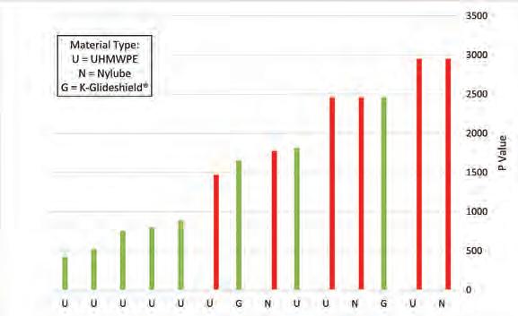 Figure 4 - Case study application factor comparisons (K-Sure support only).
Figure 6 - K-Shield Dynamax Idlers installed beneath an iron ore primary sizer.
Figure 8 - New torsion spring configuration.
forces to protect the belt. One such solution developed by Kinder Australia was the K-Shield Dynamax Impact Idler (Figure 6), the first of which was commissioned originally for belt protection then went on to increase the conveyor belt system uptime, requiring fewer unscheduled shutdowns to replace failed rollers and idler frames.
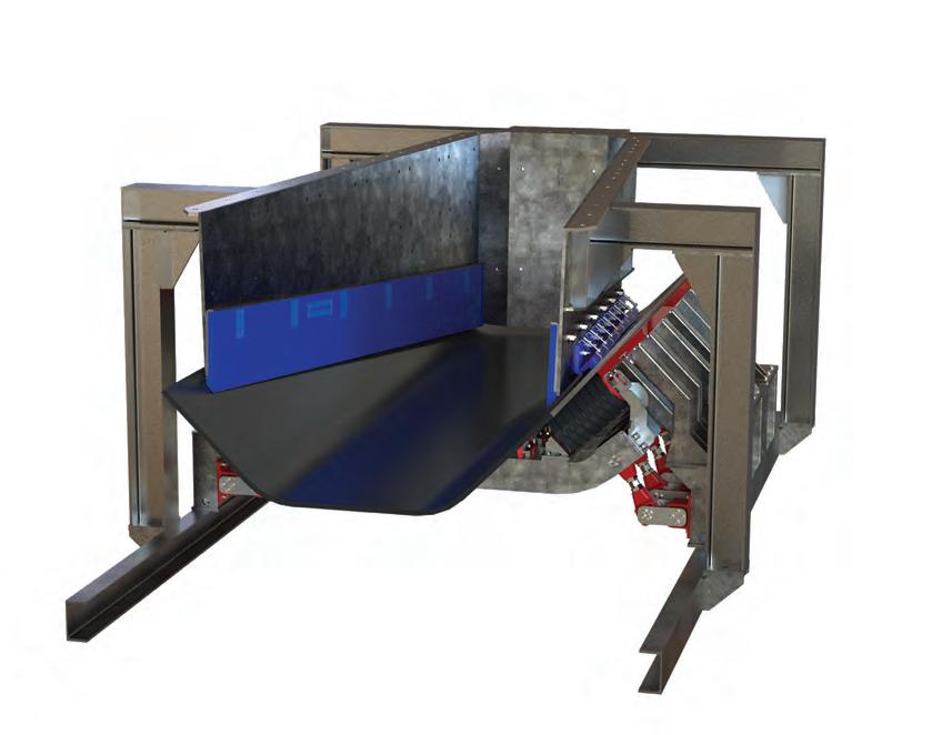
This site has seen shutdown cycles
This minimum 30 per cent belt life improvement makes savings on a belt change that is reportedly a $250k exercise (as of 2019, likely much more now), not to mention the opportunity to allocate the labour elsewhere on site for shutdown works. With roller and idler frame sets lasting four to six weeks prior to the Dynamax Idler install, requiring unscheduled shutdowns of the conveyor
multiple shut cycles before offering any preventative maintenance on these items.
Impact force measurements were taken from our K-Shield Dynamax Impact Cradle (Figure 1). We can observe the recorded data, as one load cell was used per spring (independent). It was also possible to observe the impact loading live on site via the control box.
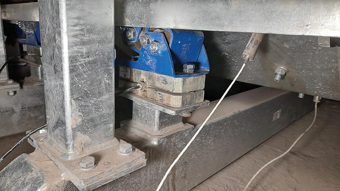
With so much data taken over many weeks, it was necessary to seek data of interest. For Kinder this was the peak readings. On many occasions, it noted that higher force readings were recorded on the lead in and lead out torsion springs. Due to the six-spring layout, this leads Kinder to believe that under lump impact the trough panel is rotating about the centre springs.
As this was Kinder’s first attempt at data capture in a load zone application, further improvements will be made to the data collection system for another attempt at baseline data and subsequent belt support system installation. A summary of these improvements are:
Ensure baseline data can be obtained accurately.
Consider other load cell types and data capture that can produce higher frequency data collection to ensure peaks are accurately captured.
CONVEYORS
Figure 1 - K-Shield Dynamax Impact Belt Support System with temperature and impact force data measurement devices.
Figure 9 - Tapered chute assembly.
Improve temperature capture to achieve more reliable data closer to the heat source.
• Installation to a harder/denser rock or ore carrying system.


Another case study pushed the innovation boundaries to further soften, control and allow adjustment of the spring configuration, as well as incorporate some other improvements from other belt support systems. Kinder’s client opted to incorporate a tapered chute on this troughed system. They realised the issue of skirting related wear to the belt and opted to spread this over a greater area. This further pushed Kinder Australia to come up with a completely bespoke system to ensure the dynamic section too followed the tapered shape of the chute.
Combi design to remove a significant quantity of friction.
• Polyurethane isolation bushes incorporated to all impact loaded rollers.
• Pre-tension of one torsion spring

to further dial in the dynamic system behaviour.

• Completely independent dynamic sections to ensure springs are less likely to work together producing a higher (harder) spring rate.
Spring assembly is more open, making build up issues less likely.
• Lead in rollers ensures excessive pressure on slider rails will not occur
DESIGN & CERTIFICATION 3D MODELLING AGI SILOS TRUSTED BY THE INDUSTRY FOR QUALITY DESIGN & CONSTRUCTION AGI CONVEYORS DESIGN, BUILD & CONSTRUCT www.alliedgrainsystems.com.au Young, NSW & Toowoomba, QLD 1800 689 433 Australian owned and involved in Australian Agriculture since 1911
To read the full report, visit kinder.com.au
Figure 10 - K-Dynamax Combi Impact Cradle ready for shipping
Automated CAD design to meet requirements
Aspec Engineering recently provided engineering support for a client that was upgrading part of its wharf-based rail infrastructure. Paul Munzenberger explains how the company used automated computer-aided design (CAD) modelling to complete the project.
ASPEC ENGINEERING RECENTLY completed a project assisting one of their clients to upgrade a section of their wharf-based rail infrastructure. The project involved the replacement of worn rails, the replacement of corroded rail sole plates and sole plate grout, and the improvement of the rail alignment.
In addition, the project also involved a redesign of the rail support system to improve the clearance envelope around the rail to allow the installation of long travel rail clamps on the wharf machinery operating on the rails.
The major engineering task for the project was the design of a new set of sole plates and the fixing of these to the wharf.
Sole plates are steel plates that bolt to the concrete structure beneath them and support the rail above. The sole plates are fitted with weld-on rail clips that locate and retain the rail horizontally and jacking bolts to aid with installation.
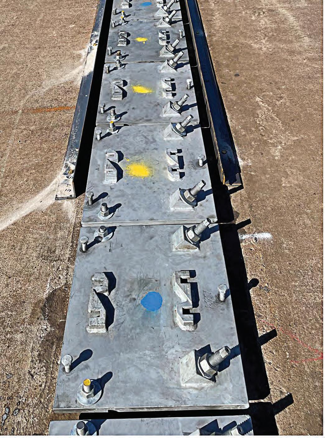
The new sole plate design was required to interface to the existing fastener infrastructure that was cast into the concrete wharf rail beam. Here, the angled bolts, shown in Figure 1, were a particular challenge. The position of the rail clips was also carefully considered so that the new rail could be installed closer to its design alignment while allowing adjustments to align the new rail with existing rails on adjacent wharves.
The 3D scan of the existing infrastructure confirmed that the irregular alignment of the fasteners in the wharf would complicate the design. This meant that the design of every one of the roughly 1200 sole plates would be unique. The potential for drafting errors was high and the sheer amount of work required to manually produce a set of models and files for profile cutting would have been excessive. Also, the short timeframe of the project would have precluded any changes or updates to the design if drafting had been carried out manually.
Aspec has previous experience with wharf rail upgrade projects. These projects were documented manually for smaller lengths of rail which included the irregular fastener alignment similar to the current project. These projects took a great amount of time to produce the irregular sole plate design drawings and it was obvious that manual generation of roughly 20 times more sole plates for the new project would cause schedule issues. Tt was decided to employ automated CAD modelling to draw the plates and to create individual files for each one.
ENGINEERING 54 І Australian Bulk Handling Review: July/August 2023
Figure 1. Rail sole plates during installation.
Automated CAD Design
The development of the sole plate profiles was part of an involved process which is simplified into four major steps. The process began by determining the location of the existing fasteners. This was carried out by surveyors via 3D laser scanning. The resulting point cloud was then manually manipulated to determine the centre locations for the fasteners as well as the alignment of the two rails. The coordinates were then read by a custom coded program that plotted the circles and rectangles at each fastener location.
Finally, based on the location of the fasteners, the outside edge of each plate and the three jacking bolt locations were plotted along with the unique plate number and the rail clip position outlines that would be etched into the sole plates.
The time savings in using automatically generated drawings are obvious, however, there were other benefits presented by the process. Chief among these was the reduction, and ultimately elimination, of errors. Since all the files were created with the same code, once it was proven that a small number of sole plates had been drawn correctly, it could be relied upon that the remaining files would also be correct. This would not be true for hand drawn sole plates as each plate would require independent verification at each design iteration.
The DXF files produced for each plate were fed directly into the plate profiling process; however, details of each plate were required for quality assurance (QA) and future reference. The development of the QA data was efficiently developed using the automated CAD process. To verify the plates were cut and fabricated correctly, a table of dimensions was produced for each plate. The programming generated the required dimensions as part of the sole plate drawing process, and it was a simple matter to write these dimensions into a table that could be used by the profile cutters and fabricators to verify their work.
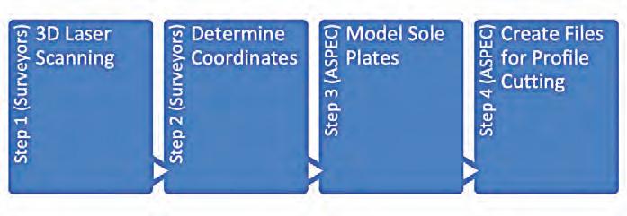
The automated CAD process
also allowed the design to evolve as more information became available or when the design concept changed. After the programming was completed for the first iteration of the sole plate design, the design changed several times to optimise the project outcomes. These changes were made in short time frames, with a new full set of part files being available immediately upon completion of programming.
The data that were generated by the automated CAD design program was useful for other parts of the project as well. For instance, the program data were used to quickly calculate the volume of grout based on the survey data and assisted with planning for the new rail alignment and rail transitions to the existing rail on adjacent wharves.
The program was used to determine the coordinate locations of each plate so that installation of the sole plates could be progressed from multiple points along the rail rather than from one end to the other in numerical order. New rail coordinates were also easily generated to assist the surveyors with the alignment of the new rail to the agreed alignment.

Conclusion
The rail upgrade project was completed several weeks ahead of schedule. This was in large part due to the ability to produce fast sole plate design updates with a high degree of accuracy, allowing refinement of the design to achieve optimised installation outcomes. The incorporation of automated CAD design programming techniques to produce the part files enabled the required design updates and the production of files before the deadline for fabrication of the sole plates. The availability of accurate QA data assisted the fabricators to verify the plate dimensions quickly and the procedurally generated sole plate coordinates and rail alignment assisted with the fast installation of the new sole plates and rails.
Ultimately, the use of automated CAD design procedures to generate the sole plate designs with computer code proved to be highly successful. Future rail upgrade projects and any other projects that lend themselves to creation of large numbers of similar, but unique components using automated CAD design processes will benefit from using these design methods and lessons that were learnt during this project.
Australian Bulk Handling Review: July/August 2023 І 55
Figure 2. Key project steps
Figure 4. Completed sole plate installation after grouting and rail installation.
STEVE DAVIS
Steve Davis discusses Australia’s bulk handling sector, highlighting the advancements the industry has made and the organisations that are providing local innovations and expertise.
Steve has worked in bulk handling for 30 years, for both resource companies and professional engineering firms, in Australia, South Africa, the Middle East and Canada. His experience encompasses such commodities as iron ore, coal, potash, phosphates, petcoke, sulphur, sands and grain.


Managing conveyor feed
CONVEYORS ARE USUALLY designed to carry throughput in a process and are often specified based on an average tonnes per hour demand. For example, a plant operates at nominal annual throughput of 10 million tonnes per year, with availability of 85 per cent. Conveyor flowsheet design would be 1,343 t/h. To design a conveyor, we must consider whether it has a surge function, perhaps to refill an empty stockpile at a high rate, and how the feed to the conveyor is controlled. The surge function is managed by increasing the design rate, potentially to support the maximum possible upstream feed rate, such as a conveyor fed by a crusher that has a finite limit of 2,500 t/h average. Surge from the
upstream equipment may also need to be accommodated – the crusher may average 2,500 t/h but instantaneous flow through the crusher might be double this if the feed in contains fine ‘wash through’ material. In other situations, the conveyor must not feed more than the design rate, or the downstream process will suffer. Management of feed to the conveyor once this design throughput is fixed is critical to good operation.


Belt conveyors have capacity defined in two ways. The belt has a volumetric limit defined by the allowable cross section of material and belt speed and has a throughput capacity defined by the drive (motor, gearbox) and the mechanical components of the conveyor (belt, pulleys,
idlers). As the conveyor will be designed to start under worst case conditions – fully loaded and with a blocked feed chute – the mechanical components generally have a significant design margin over the steady state operating condition. For example, at design load and 100 per cent speed, the conveyor may carry a large overload without tripping out. This assumes that structure and power supply are adequate, and that the drive has been set up to match the demand from the conveyor under all normal operation.
The consequences of overfeeding a conveyor mechanically include higher wear on components, potential failure in operation, stalling the conveyor with reduced availability and

CONVEYORS 56 І Australian Bulk Handling Review: July/August 2023
Overfeeding can be the result of incorrect design capacity, incorrect bulk density or surcharge angle.
talk
Good feed management is critical for a conveyor system. Steve Davis discusses how to achieve it.
increased maintenance cost. It is practical to increase mechanical capacity on many conveyors, however this may not resolve volumetric issues.

The consequences of overfeeding a conveyor volumetrically include choking the downstream process, excess spillage if the usable cross section of the belt is exceeded, and stalling the conveyor if the drive capacity is exceeded. Overfeeding can be the result of incorrect design capacity, incorrect bulk density or surcharge angle, poor belt loading or surge belt loading, or poor control of feed to the conveyor.
Volumetric capacity of a troughing belt is limited by the recommended edge distance. Edge distance gives a margin of capacity when the belt is 100 per cent full at a defined surcharge angle. This margin limits spillage when the belt drifts slightly and when the largest particle rolls to the edge of the belt. It is common practice to design at 80 per cent of the nominal capacity to provide additional
edge margin for some variation in the material properties. This design basis assumes a continuous feed at design feed rate and with the selected material profile on the belt. It makes no allowance for feed variables, which must be added in, managed by procedure, or designed out. Designing conveyors with high volumetric loading to reduce belt width and hence cost gives a high operating risk unless the bulk material properties are constant and well defined.
If bulk material parameters are incorrect or vary with time, the conveyor may not be able to carry the design throughput. Density variation, where lower density increases the volume on the belt, can lead to spillage. Low surcharge angle, which can be the result of feed chute performance or material properties will reduce edge distance and spillage is more likely. Both can occur and when combined with poor feed control to the conveyor, the result can be significant spillage. Spillage is a high operating cost
and often leads to significant damage.
Feed control should be considered where there is gravity or mechanical reclaim from stockpiles or silos to conveyors. Wheel loaders reclaim from ground stockpiles through hoppers is a common reclaim method, often with two or more hoppers in use at the same time. If hopper discharge is not managed, receiving conveyor loading is highly variable. Gravity reclaim from stockpiles and silos is effective but is variable due to level of fill and material properties. Outlet design to prevent arching and ratholing will often allow much higher flow rates than required. Stockpiles and silos often use multiple reclaim points and can be ‘force fed’ when clearing. Feed control should be used to consistently load receiving conveyors.
Crusher discharge, whether primary or later in the process, varies over time with the material feed and the condition of the crusher. A high percentage of fines will ‘wash’ through a crusher, and a

PROACTIVE TODAY PRODUCTIVE TOMORROW visit us at kinder.com.au
conveyor is installed to accommodate the maximum flow, in which case the flow is managed in the next process stage, usually a surge bin or stockpile with discharge feed control.
Bulk material screens typically split flow into two or more streams based on particle size. Feed particle size distribution is rarely constant, resulting in continuously varying flow splits. In most cases the receiving conveyors are sized for the maximum likely flow of each split fraction and the cost and complexity of controlling feed is avoided.
In circuits that recycle material, such as a secondary crusher and screen where crusher discharge oversize is screened and returned to the crusher, the recycle stream can build up to double or more of the steady state operation at times. This is usually managed by oversizing the conveyor.
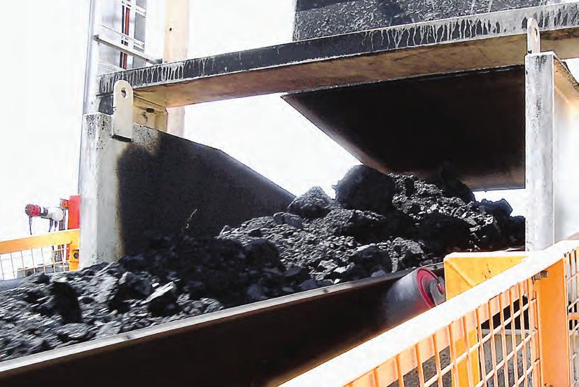

Many types of filters have discontinuous discharge. Slabs of filter cake are discharged regularly with nothing between. The receiving belt must absorb the impact of the falling material and move it away before the next discharge. Conveyors receiving feed from multiple filters must assume at least one overlay in the design.

Another aspect of material handling where conveyor design must manage discontinuous flow is where trucks, trains and ships are loaded and unloaded. Unit
rate. This is generally managed by feed and discharge surge hoppers or bins which control feed and allow feed and receiving conveyors to be designed for the average. As railcars and trailers have low capacity, the surge capacity is generally small.
Continuous train loading and unloading, which can exceed 10,000 t/h, utilise 75 to 90 per cent of the cycle for material transfer. Surge hoppers and feed control are provided to minimise impact from upstream and to downstream operation.
issues. Material is mostly conveyed to or from storage facilities where capacity is sufficient to load or unload the complete ship. Loading interruptions are managed by stopping the feed system. Grab crane shipunloaders must have a wharfside hopper and feed control onto the conveyor as material is discharged over 10 to 20 percent of the cycle. Commonly we see ships unloaded direct to vehicles, and a wharfside hopper and feed system is used to manage the discontinuities in feed rate for continuous and discontinuous unloading.
Feed to conveyors is managed using feeders. Available types include apron, belt, combined belt over apron, vibrating, screw, oscillating pan, slot, tilting chute and others. Feeders are selected to suit the application. Apron feeders are generally used for the extremes of capacity and rock size such as discharge control for a primary crusher, smaller feeders are used for lower feed rates and finer materials.
Selecting a feeder not only provides feed control but also produces some feed management issues in themselves. Feeders are good at providing average feed rates over continuous periods of operation, however the design must consider the instantaneous delivery rates to be effective. Feeders are affected by bulk material properties and some types are more consistent than others. Apron feeders can produce a randomly
58 І Australian Bulk Handling Review: July/August 2023 CONVEYORS
Low surcharge angle will reduce edge distance and spillage is more likely.
Without good feed management the operation may suffer from excess spillage and other issues.
cohesive material. The bed fractures at the discharge point and sloughs from the end. The receiving conveyor must be capable of receiving this surging.
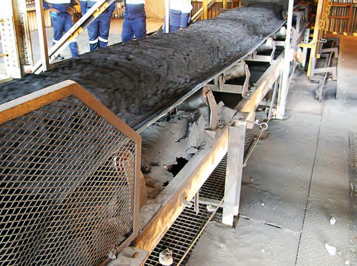
Other feeders are generally more consistent with the best operating on dry homogenous material. Each design should consider the interaction between the feeder and the bulk material and how to manage variation in the downstream conveyor system design.

We generally prefer to operate conveyors at fixed speed, but feeders are designed with variable control, some from zero to 100 per cent of nominal, others with perhaps 60 per cent to 100 per cent of nominal. Some processes manage with set point control of the feeder capacity, where the average feed rate for each set point is determined from experience. An example being a multi-use port where the grab crane discharge hopper feeder is adjusted to
the feeder and a feedback control loop to maintain the required flow. Weigh feeding might be used to control feed rate
designed precisely for flow. Without it, conveyors may need to be oversized to cope with variation or the operation may
• materials handling • asset life extension • infrastructure ASPEC Engineering provides high quality technical engineering support to mines and ports www.aspec.com.au
Conveyors must not feed more than the design rate, or the downstream process will suffer.
Good vibrations for mass flow
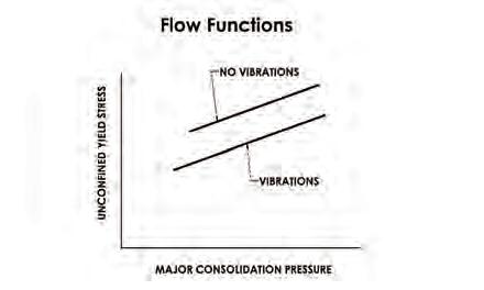
David Wilkinson compares the fundamental physical conditions necessary to produce mass flow of bulk solid feed material for gravity flow and vibratory pan type systems through a hopper typically located under a storage vessel.
TO ELIMINATE FLOW IMPEDIMENTS,
consider the hopper and feeder trough as one integrated unit, as per figure and adopt the ideal hopper/trough geometry recommended by Syntron in “Working with Hoppers”[1] as the starting point of a design.
Bulk solid flow control
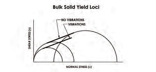
Feed rate is accurately controlled by adjusting the trough amplitude of a two-mass vibe feeder or the frequency of a single-mass vibe feeder. Changing the gate position is not recommended for rate control as it can create geometry that may cause problems with the flow. The gate can be adjusted slightly to cater for variations in bulk density and flowability of the material being handled, however it is best used for isolation to help facilitate maintenance. The control of gravity flow systems by belt and screw feeders is far less accurate and reliable due to the areas of flow stagnation as explained below. This can lead to material build up and possible blockages.
Jenike direct shear test cell
Bulk material’s physical properties are measured using a standardised Jenike Shear Test Cell. In “Influence of Vibrations on the Strength and Boundary Friction Characteristics of Bulk Solids and the Effect on Bin Design and Performance” Roberts, Oom & Scott’s [3], the effect of vibrating halves of the shear tester for a pyrophyllite bulk solid is investigated. Similarly fine limestone and titania powders investigated by Kollman and Tomas in “Effect of Applied Vibration on Silo Hopper Design”[4] similar results which are consolidated into the general diagrams below where “the angle of internal friction remains constant and the yield loci is shifted parallel towards smaller shear
The relation between vibe and no vibe yield loci and flow functions shown in figure 1 and 2 can also be expected in real integrated hopper-feeder applications as introducing vibrations moves the flow function down. This enables mass flow at lower values of unconfined yield stress and major consolidation pressure.
The flow function is determined from the instantaneous yield loci. It simulates the bulk solid failure states. Note however Roberts, Kollman and Tomas have only investigated devices that vibrate the hopper wall or bin activators and have not considered a vibrating feeder pan. Accurate data on feeder installations is scarce so a qualitative approach is taken here.
It can be difficult, although not
Bin hopper flow systems

Installations where a circular bin is added onto a hopper will increase the fill pressure onto the consolidation pressure already present in the hopper. As bulk granular materials having cohesive properties, moisture, and very fine particles (typical in powdered bulk solids, coal and ore fines) tend to stagnate flow and so they commonly require vibration or air cannons to break up lumps. Fine powdered bulk solids will require careful evaluation considering particle size and density to achieve a workable solution.
It is more common for flow to partially or totally stagnate (funnel flow, ratholing) when belt or apron feeders are used under a hopper without vibrations to reduce the bulk material internal friction.
VIBRATION 60 І Australian Bulk Handling Review:
Fig 2 – Flow functions comparison.
Figure 3 – Effective area of an apron and belt feeder hardware.
Figure 4 – Effective area of outlet in a screw feeder.
Fig 1 – Vibe and no vibe shear cell results comparison.
can occur when a large vibrating surface of a feeder is absent. A meaningful comparison between the feeding methods is illustrated by the amount of dead feed.
As the effective area of a vibe feeder pan in contact with feed is much larger than the effective area of a belt or apron feeder’s chain and bar gear, the capability to move bulk feed volumes is vastly different.
Discrete Element Modelling (DEM) in figure 5 shows excitation forces inducing particle movement up into the hopper, breaking up any stagnation or dead zones.
Beware of rock box add-ons. Intended to reduce wear, they can compromise hopper throat and gate geometry and can introduce severe throttling of flow due to the increased internal friction reducing bulk material transport velocity.
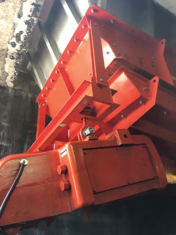
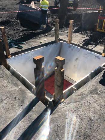
Eliminating coal fines arching
Fines and other cohesive material can still support an arch over a hopper opening even with a vibe feeder if it falls short of the criteria defined in “Flow

Properties and Design Procedures for Coal Storage Bins” by Brian A. Moore.[7]
This was the case at Clarence Colliery NSW where an existing coal fines hopper discharge opening continually blocked preventing coal blending. Opening the hopper transition output shown in figure 6, above the critical arching dimension coupled with the effect of the vibe feeder pan enabled mass flow.
Quantifying vibration effects
Syntechtron uses a simple vibration factor Vf shown in the equation below, derived from “Effect of Applied Vibration on Silo
unconfined yield strength = Vf x function (major consolidating pressure) x scaling
where Vf = constant + Fn (gate)
Belt and apron feeders
Apron feeders are effective in handling large lumps and cope well with damp fines, however they are expensive and have higher levels of maintenance. Belt feeders are effective as conveyors transporting bulk materials over long distances.
Good vibrations
For a wide range of feed applications vibratory feeders conserve plant height and footprint. They also reliably deliver feed at an easily controlled rate. The only maintenance required on resonant electromagnetic type feeders is the replacement of wear liners in the trough over an expected 40 year service life. Similarly for bulk solid material stockpiles, mass flow and larger capacities can be expected by installing vibratory stockpile reclaim equipment [11]
REFERENCES
1. Working with Hoppers – Syntron Materials Handling, LLC.
2. Syntechtron is the Australian licencee of Syntron MH Mississippi USA.
3. Influence of Vibrations on the Strength and Boundary Friction Characteristics of Bulk Solids and the Effect on Bin Design and Performance - A.W. Roberts, M Ooms and O.J. Scott, Australia.
4. Effect of Applied Vibration on Silo Hopper Design - Th. Kollmann and J. Tomas
5. Storage and Flow of Solids – Andrew W Jenike
6. Flow Properties Testing of Limestone Samples Mincore – Andrew Grima & Jon Roberts, Bulk Materials Engineering Australia, University of Wollongong
7. Flow Properties and Design Procedures for Coal Storage Bins – Brian A Moore, University of Wollongong.
8. DEM Feed Hopper Transition Bluescope Ship Unloader No3 – Brad Glass Avesta
9. Feeders for Bins and Hoppers – H.Colijn and P.J. Carroll- Materials Handling Magazine Article August, 1970 Vol. 15, No8
10. New Design Criteria for Hoppers and Bins – Dr J.R.Johanson and H.Coljn US Steel Corp October 1964
11. Vibratory Stockpile Reclaim Flow Stimulation and Control ICBMH 1998 - K. Bagust, Syntechtron
12. Performance Characteristics of Gravity Reclaim Stockpiles of Concical Form –A.W.Roberts Dean, Faculty of Engineering, The University of Newcastle, NSW
13. Vibratory feeder calculations – Robert Rudd, Syntechtron
14. Flow Properties of Powders and Bulk Solids – Dr.Ing. Dietmar Schulze, University of Applied Sciences Braunschweig/Wolfenbuttel, Germany
15. Case Study Clarence Colliery - Eliminating Feed Arching Syntechtron
Australian Bulk Handling Review: July/August 2023 І 61
Figure 7 - integrated vibe feeder and hopper.
Figure 6 – installing new larger hopper.
Figure 5: DEM of iron ore feed in a vibe feeder.
Optimising scrapers for improved belt performance: Addressing carryback issues
Dr Jayne O’Shea, from TUNRA Bulk Solids, discusses conveyor carry-back and testing techniques that can be utilised to evaluate belt scraper configurations and pressures to optimise scraper performance.
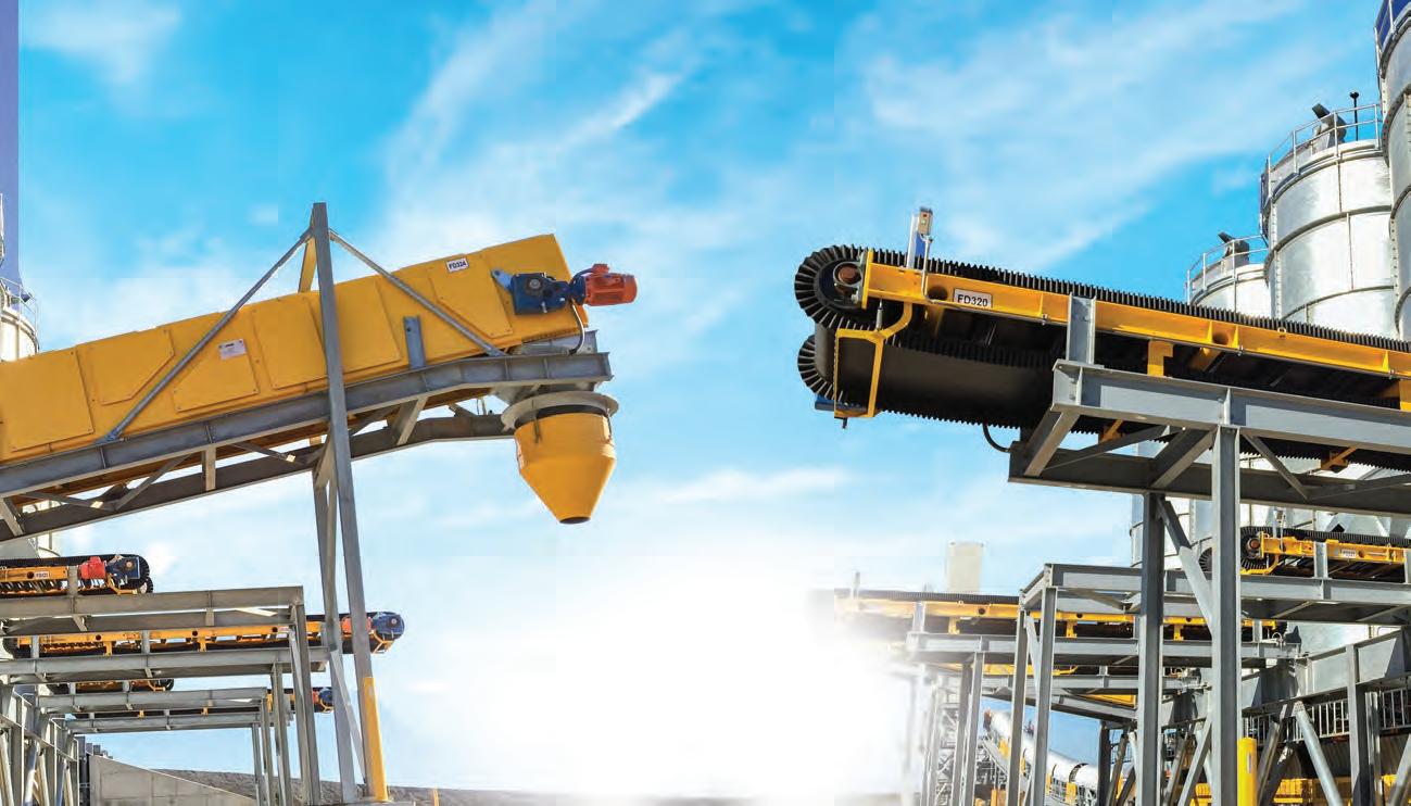
CONVEYOR BELTS face significant challenges in industries such as mining due to carryback issues. Carryback occurs when material adheres to the belt and is transported back along the return side, leading to problems like premature wear of the belt, idlers and pulleys, decreased efficiency, spillage, and reduced product quality. Additionally, frequent belt cleaning and maintenance are necessary, resulting in unplanned downtime and additional costs. To address these concerns, many companies use belt scraper systems to remove carryback. However, the effectiveness of these systems can vary, making it crucial to find the optimal scraper pressure for installation, striking a balance between carryback removal and minimising belt wear.
Belt scraper systems typically include primary scraper blades mounted
on the discharge pulley and secondary scraper blades positioned under the return side of the conveyor belt. The main purpose of these scrapers is to remove carryback, improving conveyor performance and reducing maintenance requirements. However, the effectiveness of scraper systems depends on various factors such as design, blade material, installation position, operating conditions, and the angle of attack of the scraper blades.
Research has highlighted that finer particles tend to move toward the belt surface, and moisture content affects the adhesion and cohesion characteristics of bulk material [1, 2, 3] The surface roughness of the belt also influences the extent of carryback.
To optimise scraper performance and evaluate their effectiveness, testing protocols can be employed where
different scraper configurations are assessed under simulated operating conditions. These tests enable engineers to compare the performance of various scraper designs by measuring their efficacy in removing carryback. The test facility located at TUNRA Bulk Solids, The University of Newcastle, can be used for belt scraper performance testing.
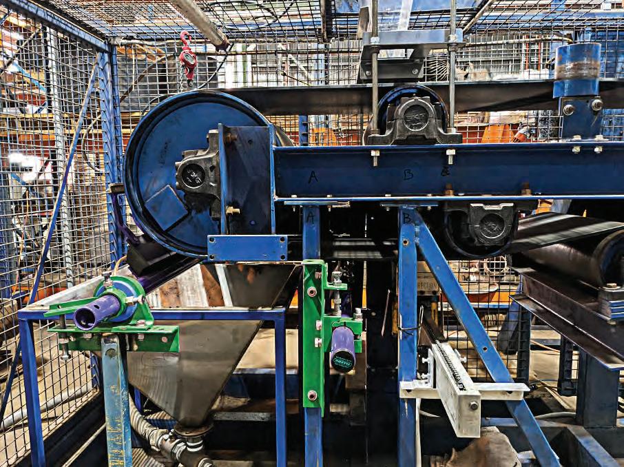
This test facility includes a recirculating system with a discharge hopper that evenly distributes bulk solids across the width of the conveyor belt’s top cover. The primary and secondary cleaners scrape the bulk material off the belt, which is collected in a lower storage hopper. The carryback adhered to the belt surface after passing through the cleaners is measured using the TUNRA carryback measurement system. The amount of carryback is quantified and presented as a value per area of the belt or per unit of time [6, 5]
Testing was conducted as part of a recent project to compare the effectiveness of four different belt scrapers in removing iron ore carryback, utilising the test facility. Figure 1 presents a summary of results averaged over three tests, with the scraper tensions set at eight kg and 15 kg. The results are expressed in kg per hour.
When installing scraper blades, two important factors to consider are the angle of attack and pressure. The angle of attack refers to the angle at which the scraper blades make contact with the belt surface, and two common approaches to scraper blade configuration are peeling and scraping [1]. In the peeling configuration, the scraper blade initiates contact with the belt at a shallow angle, gradually peeling off the carryback
BELT SCRAPERS 62 І Australian Bulk Handling Review: July/August 2023
Belt cleaning test facility located at TUNRA Bulk Solids, The University of Newcastle.
material. This approach is effective for removing loosely adhered material and minimising belt wear. Conversely, in the scraping configuration, the scraper blade directly contacts the belt at a steeper angle, exerting more force to scrape off stubborn or tightly adhered material. However, this approach may increase belt wear due to higher friction

and scraping forces. To determine the optimal angle of attack for scraper blades, it is essential to consider the material characteristics, belt properties and operating conditions. Peeling angles are often preferred when dealing with loosely adhered carryback and minimising belt wear is a priority, while scraping angles are suitable for
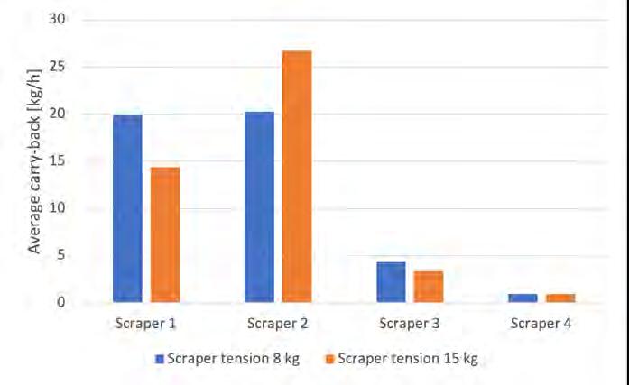
applications involving stubborn or tightly adhered carryback, but they may result in increased belt wear.
Scraper pressure plays a critical role in effective carryback removal. Insufficient pressure can result in incomplete removal, reduced conveyor performance, and increased material spillage. Conversely, excessive pressure can lead to excessive belt wear, causing premature failure and downtime.

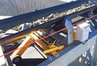

Belt scraper systems typically include primary scraper blades mounted on the discharge pulley and secondary scraper blades positioned under the return side of the conveyor belt. The main purpose of these scrapers is to remove carry back, improving conveyor performance and reducing maintenance requirements.
WEIGH BELT FEEDERS Mild Steel Powder Coated for Quarry and Mine installations or Stainless Steel construction for the Food Industry or the Harshest Environments. Throughput up to 1,000 TPH CONVEYER BELT SCALES For Belt Widths between 450mm and 2,000 mm accuracies of +-0.5% for a single idler and +-0.25% for a dual idler VOLUMETRIC FEEDERS For Volumetric or Gravimetric Loss in Weight Applications. Auger Sizes up to 152mm diameter and 20,000 Litres per Hour Contact Tecweigh Website www.tecweigh.com.au Email sales@tecweigh.com.au VIC: 03 9775 0266 | NSW: 02 9159 9160 | QLD: 07 3184 0980 | WA: 08 6558 1936 CUSTOM ENGINEERED WEIGHTOMETERS & WEIGHING SOLUTIONS Manufacturer of conveyer belt scales (weightometers), weigh belt feeders and volumetric and gravimetric auger feeders all manufactured in australia
Figure 4: Comparison of Average Carry-back.
Achieving the optimal scraper pressure involves striking a balance between carryback removal and belt wear. While a universal solution does not exist due to variations in operating conditions, belt characteristics, and material properties, testing offers valuable insights for determining an optimal pressure range. By systematically adjusting scraper pressures in controlled test environments and evaluating the results, engineers can identify the pressure that maximises carryback
pressures, carryback levels are high due to a larger effective cross-sectional area between the belt and scraper blade profiles caused by minimal indentation of the blade into the belt’s top cover. As pressure increases, belt deformation reduces the mean surface roughness, resulting in a decrease in the effective cross-sectional area and a reduction in carryback. When the pressure applied to the blade exceeds approximately 80 kPa, the amount of carryback gradually increases. The higher force applied to the
Conclusion
Carryback presents persistent challenges for industries relying on conveyor systems, impacting operational efficiency, maintenance costs, and the longevity of belts and belt components. Fortunately, scraper systems offer a viable solution to mitigate carryback-related problems. However, the effectiveness of scrapers depends on careful evaluation of scraper configurations and pressures. By striking the right balance between carryback removal and belt wear, companies can optimise their conveyor systems, improve operational efficiency, and achieve sustainable reductions in maintenance costs.
removal while minimising belt wear.
To illustrate this, the results from carryback performance testing performed at the University of Newcastle, with conditions described in [6], are shown in Figure 2. The results showed that the optimal pressure range for minimising carryback for the tested arrangement was between 60 and 80 kPa. At lower
belt scraper blade causes the leading edge of the contact surface to lift off the belt as the blade pivots, thereby enlarging the effective cross-sectional area between the belt and the blade. These findings emphasise the importance of selecting the appropriate pressure range to effectively manage carryback and optimise conveyor belt performance.
Findings from carryback performance testing can provide crucial insights into the factors influencing belt cleaning efficiency. Scraper selection, tension adjustment, and maintenance all play pivotal roles in effectively mitigating carryback. Through thorough evaluation of scraper configurations, optimisation of pressure, and implementation of proper maintenance practices, companies can successfully address carryback issues, enhance operational efficiency, and extend the lifespan of their conveyor belt components.
References
1. R. Versteegh, “Design of a belt scraper test facility,” TUDelft, Section Transport Engineering and Logistics, 2006.
2. A. W. Roberts, M. Ooms and D. J. Bennet, “Bulk solid conveyor belt interaction in relation to belt cleaning,” International Journal of Bulk Solids Handling, vol. 7, no. No, June 1987.
3. M. Rhodes, Introduction to particle technology, Chichester: Wiley & Sons Ltd, 1998.
4. A. Roberts, L. A. Sollie and S. R. Silva, “The interaction of bulk solid characteristics and surface parameters in surface or boundary friction measurements,” Tribology International, vol. 26, no. 5, 1993.
5. S. Wiche and A. Roberts, “Critical carryback and belt cleaning issues. Modern Concepts in Belt Conveying,” in Course Notes - Chpt 6, The University of Newcastle, 1999.
6. C. Wheeler, R. Versteegh, G. Lodewijks and A. Roberts, “Experimental simulation of conveyor belt cleaning,” in The 2nd International Conference and Exhibition for Handling, Processing, Storing and Transporting Bulk Materials, Mumbai, India, 2005.
64 І Australian Bulk Handling Review: July/August 2023
BELT SCRAPERS
Figure 2 Carry-back versus Scraper Blade Pressure [6].
Scraper pressure, which indicates the force exerted by the scraper blade on the conveyor belt, plays a critical role in effective carry back removal. Insufficient pressure can result in incomplete removal, reduced conveyor performance, and increased material spillage.
If you need a better way to store dry bulk solids, Nelson can deliver it. Nelson are totally committed to innovative design and product development, and are now engineering silos with a proven 4-leg base design mounted on load cells. This unique Nelson design development ensures accurate weight measurement. For grain, legumes, sugar and flour, and plastic granules, Nelson 4-leg design silos are available in pre-painted steel. For flour, sugar, plc and industrial powder, Nelson are building fully welded stainless steel silos, also with the proven 4-leg design, mounted on load-cells.
With the Nelson CAD programme, we have the capacity to develop a cost effective design package to meet the needs of the industry. We can then engineer your order in our own complex - with a fixed price that will save you up to 50% of the cost of on-site construction.
And Nelson can deliver, install and commission purpose-built silos, with an absolute minimum of lead time.
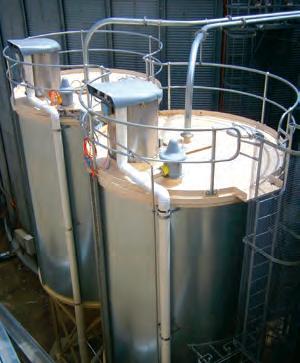
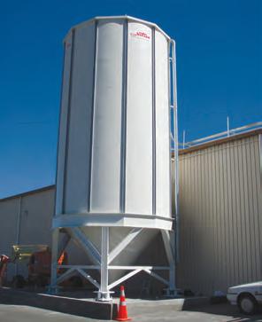


For all your bulk storage problems, please call Nelson Silos, Rochester Victoria Toll Free on: 1800 801 966 Nelson Silos Suppliers to Australian Industry nationwide T: 03 5484 1577 F: 03 5484 1593 T: 02 6862 3688 info@nelsonsilos.com.au www.nelsonsilos.com.au Head Office NSW Email Website We have technical consultants based in Melbourne, Sydney, Brisbane and Auckland (NZ) Australia’s largest manufacturer of transportable silos.
SUGAR/FLOUR STAINLESS STEEL SILO, INSULATED AND CLAD WITH COLORBOND.
Dispelling the common myths about conveyor belt scales
First patented in 1910, Conveyor Belt Scales have become ubiquitous in a wide range of applications, from mining, to aggregate conveying, to ship loading. David Hyer, Thayer Scale president, addresses the common misconceptions surrounding the technology.
FOR OVER 60 YEARS, my company
Thayer Scale has engineered and manufactured a wide range of belt scales, from the single-idler Quarry King, to our 8-idler Approach Retreat Belt Scale designed to meet the accuracy requirements of NTEP, OIML and NMI weighing.
In the decades we have been actively producing high accuracy conveyor belt scales, we have encountered several misunderstandings and misconceptions about belt weighers. In this article, we will (again) attempt to dispel these myths, and provide a little humor along the “weigh”.
Background:
In a recent article published by a technical journal, the following claims were made regarding belt scale performance:
1. Accuracy is +-1 per cent, susceptible to drift
2. Belt scales require frequent, extensive calibration
3. Conveyor belt scales must operate in a non-inclined section of the conveyor
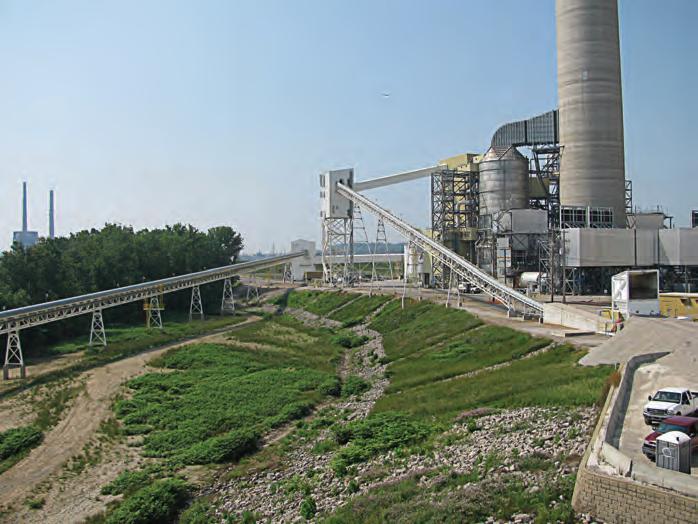
4. Operating costs are high relative to other techniques (for example: radiation-based mass measurement) This article will be the first of a series of articles addressing each of these misconceptions and will primarily deal with the issues of accuracy and drift. We will explain why in some cases these criticisms are actually quite valid – and what to do about these situations. Subsequent articles will cover calibration procedures, scale location and setup, and recommended methods to reduce operating costs.
Belt scale success is a complex problem to solve:
Belt scale suppliers have a difficult challenge in engineering a scale that can
provide better-than 0.1 per cent accuracy of a commodity that is being conveyed at rates up to 10,000 tons/hr. To accomplish this, it must:
1. Reliably and accurately measure the speed of the conveyor belt which is moving at over six metres/second.
2. Precisely transfer the vertical forces due only to the material load to the load sensor while not transmitting extraneous forces which are being generated constantly due to variations in belting, off-centre belt loading, tensions changes, etc.
3. Operate in a wide-range of environmental conditions including significant temperature and humidity variation
How do these misconceptions arise?
If you study the marketing material of the leading Belt Scale providers, you will certainly not see any of these
unflattering specifications. Accuracy is typically specified as 0.5-1.0 per cent for single-idler scales, and improves to 0.1 per cent for multiple-idler high accuracy, certified-for-trade systems. Calibration procedures are described as “routine”, and “fast”. Operating cost models are efficient and economical. So, where do these negative attributes arise?
To answer this question, it’s important to start with the understanding that the success of a belt scale installation depends on a successful collaboration between the belt scale supplier and the conveyor engineering team. Often claims made by suppliers are made assuming ideal conditions exist at the scale location. The important attributes like belt-tension, belt stiffness, idler alignment, troughing angle, take-up type, and others must be considered to maximise belt scale performance of the belt scale. To do that effectively,
SCALES 66 І Australian Bulk Handling Review: July/August 2023
Figure 1: Thayer Scale Model RF Belt Scale operating reliably on an inclined conveyor.
the parties must work together for a successful installation.
Unfortunately, often a belt scale is installed into an existing conveyor not originally engineered in anticipation of a belt scale installation. As a result, important considerations like belttension at the scale location, rigidity of the stringers, take-up device and many others are not factored into the engineering process, resulting in lessthan-optimal performance.
Accuracy fact vs. fiction
Let’s start with the ever-important issue of accuracy. In the 1960s, Frank Hyer, (my father), in collaboration with Hendrik Colijn, developed mathematical models that describes how various conveyor parameters interact and affect a conveyor belt scale. These models have been further refined over several decades to account for a wide range of accuracy-related issues and have been validated in numerous real-world installations.
The Hyer model uses strain-energy methods, and mathematically treats the belt as a continuous beam. Without diving into the derivation of the model (or dealing with differing units of measure), the simplified model of the force on a horizontal (non-inclined) scale can be represented as:
P = (n * Q * L) + (2 * T * d / L) + (K1 * E* I * d) / L3
Where:
P = Force on the scale
n = number of conveyor-mounted idlers
Q = Belt Loading
L = Idler spacing
T = Tension in the belt at the scale location
d = Misalignment between the scale idlers and the adjacent idlers
K1 = Constant related to units selected
E = Modulus of elasticity of the belt
I = Moment of inertia of belt carcass
From this model, we can derive a set of equations that represent errors that will exist (not able to be calibrated out), due to belt tension variation, idler misalignment, and belt stretch as:
E% = K1 * (d *(TR – TC)) / (n*Q*L2) – K2
* (TR – TC)) / (E * A) – K3 * ((TR – TC) *
Wb)) / 100 * (E * A * Q)
Where (in addition to the terms above):
E% = % Error
K1, K2, and K3 represent constants related to units
TR = Belt Tension while conveyor is running
TC = Belt Tension while conveyor is in calibration
A = Cross sectional area of belt carcass
Wb = Weight / length of the belt itself
Although this appears to be complicated formula, we can simplify it as:
E% = (Error due to belt tension effect on misalignment) + (Speed measurement error) + (Belt Stretch Induced error)
So, really the discussion about accuracy can be narrowed to a discussion about controlling belt tension, minimising the adverse effects of tension variability (especially the differences in tension that exist when the conveyor is running versus when it is being calibrated), minimising idler misalignment, reducing the sensitivity of the scale to idler misalignment, and finally establishing a calibration and material testing (K-factoring) process that enables frequent calibrations with minimal strain on personnel and equipment. With this in mind, let’s look at the two primary tools at our disposal to impact these variables.
1. Conveyor design
2. Scale (weighbridge) design and installation
A detailed review of each of these issues is beyond the scope of this paper, but here are some general guidelines regarding each as it pertains to accuracy.
Conveyor design
As mentioned earlier, the success of a belt scale installation (in terms of accuracy) cannot be guaranteed without considering the environment in which the scale will operate. That environment
is the conveyor itself. Thayer Scale, and other quality suppliers, perform a detailed analysis of the conveyor attributes prior to generating a proposal or quotation for a belt scale. Important aspects of the conveyor, material, and environment will be collected in an Application Data Sheet for review by the design engineer responsible for the belt scale. In many cases, during this process we will identify major obstacles that must be overcome to achieve success. Excellent guides are available online documenting all the key criteria for a belt scale installation.
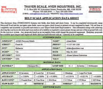
In terms of accuracy, the most important factors that need to be considered are:
- Scale location
The primary rule that applies to the scale location is to locate the scale in the area of lowest tension on the conveyor. Normally this location is near the tail pulley of the conveyor. As discussed above, high belt tension is a problem for belt scale accuracy. In addition, material needs time to settle on the conveyor prior to passing the scale, so the scale must be located sufficient distance from the end of the feed point. This can range from one metre to seven metres depending on belt speed.
- Take-up (tensioning device)
A vertical, gravity take-up is recommended for high accuracy installations. Screw take-ups are not advisable for use with belt scales as they lack the flexibility required to maintain consistent tension under varying loading conditions.
- Idlers / troughing angle
Flat single roll, or three-roll inline troughing idlers are required on the scale weigh bridge and two to three idlers on either side of the scale. Avoid the use of catenary or garland idlers. Scale idlers must be uniform and must meet CEMA (or equivalent) ratings for TIR. Use scalequality idlers on the five idlers before and after the scale location.
- Conveyor inclination / concavity / convexity
Inclined conveyors must not exceed the angle at which material will slide backward on the conveyor. The inclination of the conveyor should be fixed at one angle. If curves are required, the scale should be installed so that the belt is always in contact with all the idler
Australian Bulk Handling Review: July/August 2023 І 67
Figure 2: Application Data Sheet - Thayer Scale
rollers. In general, the scale should be located at least 12 metres from the point of inflection for a concave curve, and at least four metres from the point of inflection of a convex curve.
- Stacker / reclaimer
Although variable incline stacker/ reclaimer can accommodate a belt scale, the variation in incline, as well as the relative instability of the conveyor makes a stacker reclaimer a poor location for a high accuracy installation.
- Material loading points
Use a single feed point if high accuracy is a requirement. Multiple feed locations result in significant variation in tension, which as we know creates accuracy challenges.
Weighbridge design
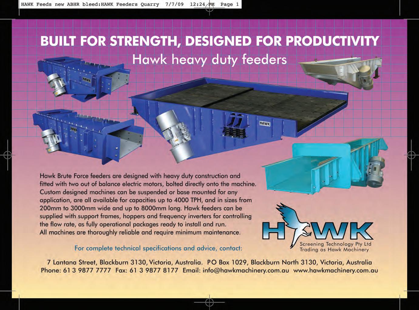
Once the scale location, and conveyor design has been finalised, we can move on to a discussion about selecting a Weighbridge design to maximise accuracy. The topic of weighbridge design obviously encompasses other areas for discussion (like ease-of-installation, type and size of test weights used for calibration, easeof-maintenance, etc.), but for this article we will narrow the discussion to issues related to accuracy only.
There are predominantly three classes of conveyor belt scale; full floating, pivoted, and approach/retreat (a special type of Pivoted). A full floating weighbridge consists of one or more idlers being fully supported by a scale platform that rests on two or more load cells. It can be classified as a force summing device since the vertical forces on the scale are summed by the load cells, and used to represent material load. The weight of the idlers and belt are present during load summing, so they must be subtracted (or tared) when calculating the net load.
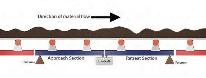


In contrast, a pivoted weighbridge consists of one or more idlers supported on a weighbridge that is anchored on one end by a pivot or fulcrum. Each idler generates a moment around the pivot, so the weighbridge can be classified as a moment summing device. The sensitivity of each idler will vary in proportion to the distance from the pivot. The idler closest to the pivot is the least sensitive idler, which provides an accuracy benefit.
Finally, an approach/retreat weighbridge is a special class of a pivoted weighbridge consisting of two independent pivoted weigh sections, one with the fulcrum upstream of the load cell, and the second with the fulcrum downstream of the load cell. The moments on these two weighing sections are summed either mechanically or through multiple load cells. Regarding accuracy, this solution offers several distinct advantages over a full-floating or a standard pivoted weighbridge. First, the two weigh idlers closest to the fulcrums are the least sensitive idlers. One of the major contributors to belt scale inaccuracy is idler misalignment. Most often, the largest source of idler misalignment occurs between the last conveyor idler before the scale, and the first idler on the
weighbridge. The relative insensitivity of this idler reduces the effect of this error. This also provides some immunity to tension variation. Second, an alignment error in the approach section of the weighbridge will be effectively cancelled by the corresponding alignment errors in the retreat section which will be of the opposite sign. Third, the pivots can be positioned in such a manner (coplanar with the centre of mass of the material flow channel), such that they eliminate, or significantly reduce the moment created by the tension pulling the material. And finally, the pivots provide a robust, stable mechanical anchor to fix the scale location when in an inclined conveyor. In contrast, a full-floating weighbridge must be held in place using check-rods or stay-
SCALES 68 І Australian Bulk Handling Review: July/August 2023
Figure 3: A full-floating two-idler weighbridge.
Figure 4: A pivoted two-idler weighbridge.
Figure 5: Approach retreat four-idler weighbridge.
rods. Check rods will generate a force/ moment couple during operation which will different significantly from that generated during calibration.
On shorter weighbridges, the relative simplicity of the full-floating weighbridge may dictate that it is worth paying the small accuracy price to gain the benefits of a generally simpler design. Although it is more susceptible to errors generated by misaligned idlers, it is usually simpler and faster to install.
Number of weighed idlers
When expressed as a percentage of the total load on the scale, the fixed errors due to belting effects become smaller as the weighbridge get larger. In addition, a longer weighbridge will permit material to reside on the scale for a longer period (residence time). This has the advantage of damping any dramatic loading variations that might exist if the conveyor is not evenly loaded. Sharp changes in loading can often be missed by the integrating instrumentation. Therefore,
it is generally the case that the highest accuracy scales will include multipleidler weigh sections. At Thayer Scale, our eight-idler certified-for-trade scale delivers +-0.125 per cent accuracy across a three to one turndown range.
One caveat to the “more idlers is better” argument is this. Some suppliers will chain together multiple single idler scales and claim that this provides the same benefits that a true multi-idler scale weighbridge provides. Unfortunately, that is not the case as the residence time on each individual scale is quite short. Summing these independent scale signals in the integrator will not overcome this problem.
Drift
Accuracy is important, but if a belt scale drifts over time that is a problem. Drift can be innocuous, and readily overcome. It could also be sinister, resulting in incorrect totalised numbers, perhaps impacting the certification-status of the certified-for-trade installation.
So, what causes drift? And what can be done about it?
The three primary causes of drift are:
1. Material build-up on weighed sections of the weighbridge, belting, and scale idlers
2. Belt-stretch induced drift due to temperature variation
3. Instrumentation-related drift (commonly associated with older instruments)
Material buildup
Over time, many bulk solids will tend to adhere to surfaces of the conveyor, belt, and idlers of a conveyor. Special care needs to be paid to this build-up of material, especially in the weighing section of the conveyor. Material buildup on scale components will add load to the scale, resulting in increased totalisation numbers. Material that adheres to rollers will alter the speed calculations used by shaft-mounted speed sensors. These sources of inaccuracy will tend to grow over time, requiring frequent calibrations.

Well-designed belt scales will include carefully engineered surfaces to minimise material build up on weighed components. Figure 1 shows the main weigh section of the Thayer Scale Quarry King, as an example. The surfaces have been designed to minimise crosssectional area reducing the possibility of material buildup. In addition, the lever arm has been engineered to avoid the possibility that material will jam between the lever-arm and the belt.
Another important feature provided by most modern belt-scales is the ability to sense when the belt is running empty, and initiate a zero-calibration during these times. An accurate zero calibration is critical for belt scale accuracy, as the zero number is constantly integrated while the belt is running. So be sure to enable automatic-zero calibrations if it is available in the belt-scale instrumentation.
Finally, another feature of many belt scale instruments is the ability to complete a calibration calculation to determine the “As Found Error” as an aggregate number. Under normal calibrations, zero and span are separately calculated, and the values are stored in the instrument for future integration. However, if the scale has operated without calibration for a period of time, performing an “As Found Error” check enables plant personnel to calculate the likely error that existed during previous operations. This error can then be used to reduce or increase the totalisation value after the fact.
Temperature variation
Significant temperature variation is a frequent operating condition for many belt scales operating in uncontrolled outside environments. Wide variation in temperature will affect different components of the conveyor, and will result in the possibility of significantly
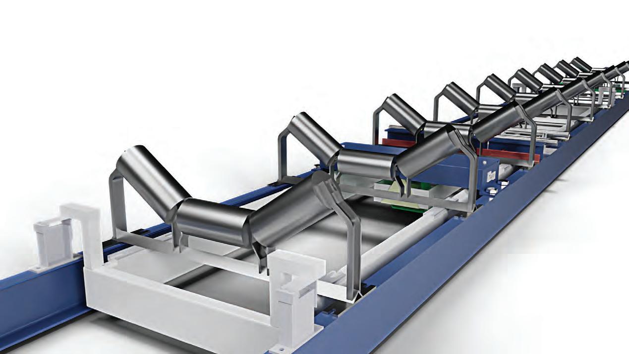
different load and speed measurements due to stretching or contracting of critical elements. Back in the 70s, belt scale instrumentation was often responsible for significant drift as much of the analogue circuitry used to load cell excitation and speed monitoring was highly susceptible to drift. Fortunately advances in belt scale instrumentation has effectively solved that problem, but perhaps the misconception has lingered to this day.
The most significant contributor to temperature-induced variation is the stretching that occurs in belt material. In severe environments where the belt will be subject to extreme temperature due to hot materials being conveyed, a heatresistant, or high temperature belt should be used. This will limit belt stretch, and provide structural stability.
To handle environmental temperature variation, high accuracy belt scales and instrumentation must incorporate a temperature sensor circuit at the scale location. This temperature sensor will provide live temperature data to the instrument enabling compensation of load and speed information as needed. To properly compensate for temperature, it is critical that the belt scale supplier perform factory temperature testing utilising an environment test chamber. In addition, since the expansion of metal in the weigh section, and in any compensating structures (stay rods for example) will affect weighing accuracy, the factory temperature testing should include these elements in addition to the load cell and speed sensor.
A few useful rules-of-thumb regarding accuracy and drift
As we have shown, there is no simple formula for determining the likely
accuracy of a belt scale installation, instead as stated above, a successful belt-scale installations requires a partnership approach between the belt-scale supplier, and the consumer. Fortunately, the long, successful history of the belt scale has enabled the industry to understand accuracy and drift issues in great detail, and this understanding has led to significantly better products, better instrumentation, and better support infrastructure. When evaluating the installation of a belt scale for high accuracy installations, keep in mind the following key points:
Rule of thumb #1 – For high accuracy installations, specify a belt scale that includes a 4-idler or larger weigh span. Rule of thumb #2 – Pay very close attention to idler alignment at the weighbridge, and at 3-5 idlers on either side of the scale. Any misalignment will result in errors on the scale. Choose a scale design that minimises the effects of idler misalignments on the weighbridge.
Rule of thumb #3 – Select a supplier that will analyse your conveyor in detail and provide a comprehensive analysis of the proper installation location, take-up recommendations and other site-specific details.
Rule of thumb #4 – Take advantage of advanced features in your belt scale integrator. For example, utilise automatic zero calibrations whenever the scale is idle. Use feature that enable temperature compensation.
SCALES 70 І Australian Bulk Handling Review: July/August 2023
Figure 6: A Thayer Scale model 6RF Approach / Retreat Weighbridge
To Australia’s only publication 100%-focused on bulk solids handling. It covers conveyors, silos, engineering, dust control, powder handling, weighing, pneumatics and much more, in industries such as mining and metals, ports and terminals, grain, fertiliser, sugar, salt, foods, milling, resins, cement and woodchips.


1 year $99.00 (inc GST)
6 issues of Australian Bulk Handling Review and 1 copy of the Equipment and Services Guide


2 years $179.00 (inc GST)
12 issues of Australian Bulk Handling Review and 2 copies of the Equipment and Services Guide
www.bulkhandlingreview.com VOLUME28,ISSUE7 | MARCH/APRIL2023 In this issue: Belts and idlers Safetyfeature Conveyorcomponents Inthisissue: Australian2023ConveyorShowcase madebulkequipment Figuringoutfeedmanagement www.bulkhandlingreview.com VOLUME28,ISSUE4 | JULY/AUGUST2023 ADVERTISERS INDEX
SUBSCRIBE
Advertiser Page Allied Grain Systems 53 All Torque Transmissions 33 Altra Motion Australia ....................................................11 Aspec Engineering 59 Astec Australia 25 Bulk Solids Modelling......................................................41 Dyna Engineering ............................................................27 ESS Engineering ..............................................................23 Flexicon BC Hawk Machinery 69 Kinder Australia ...............................................................57 Kotzur Australia ...............................................................29 Lincom Group 19 Martin Engineering 9 NetterVibration 49 Oli Vibrators 15 PackWeigh Equipment 45 Page Macrae Engineering................................................31 Regaal Rexnord.................................................................. 7 RKM Roller Company 5 Schenck Process Australia ..............................................17 Syntechtron 47 Tecweigh 63 Thayer Scale 37 Transmin IFC TUNRA Bulk Solids Handling Research .........................21 Tyre Stewardship Australia 35 Vayeron 43 AD INDEX Subscribe today: www.bulkhandlingreview.com/subscribe
Hitting a wall discharging solidified bulk material?
HYDRAULIC RAMS crush and loosen solidified bulk materials safely and easily

FULL-HEIGHT DOORS with safety interlocks disable operation when open
HYDRAULIC SCISSOR LIFT WITH TURNTABLE allows conditioning of the bag on all sides at varying heights
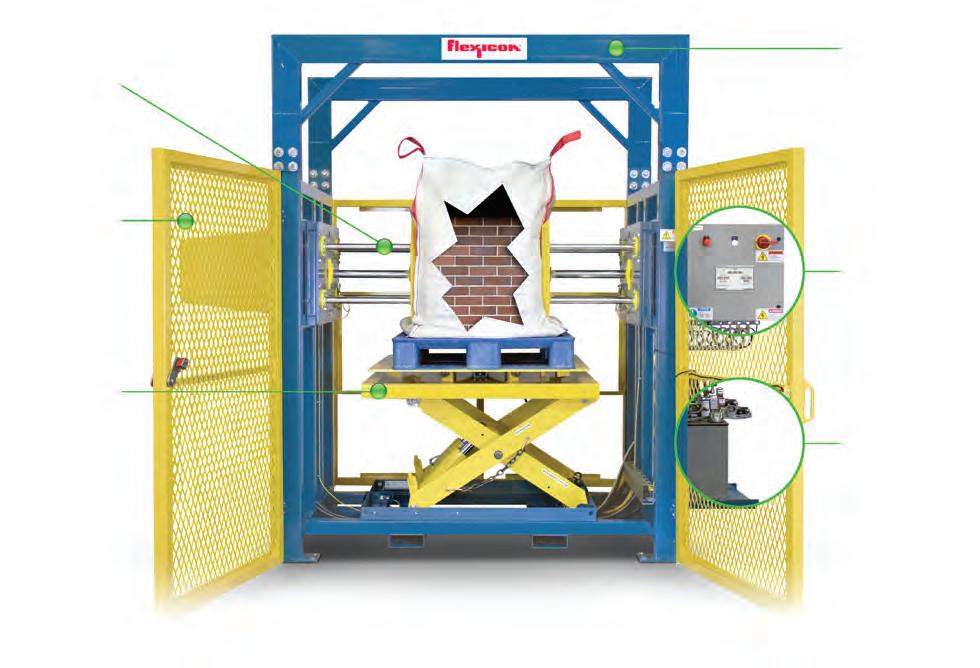
ARCHED DOORWAY MASTS increase overhead clearance for greater forklift access
PROGRAMMABLE CONTROLS allow user adjustment of bag height/rotation and number/force of ram actuations

HYDRAULIC PUMP efficiently generates the power to force rams through solidified bulk materials
No problem with BLOCK-BUSTER® Bulk Bag Conditioners
BLOCK-BUSTER® Hydraulic Bulk Bag Conditioners loosen hygroscopic chemicals, spice blends, heat-sensitive products, and other bulk materials that have solidified during storage and shipment. These self-contained systems are ready to plug in and run.
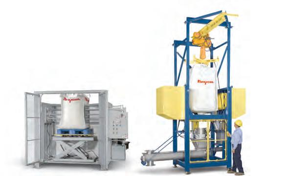
LL-0582 ©2023 Flexicon Corporation. Flexicon Corporation has registrations and pending applications for the trademark FLEXICON throughout the world. AUSTRALIA sales@flexicon.com.au 1 300 FLEXICON +61 (0)7 3879 4180 USA SINGAPORE INDONESIA MALAYSIA SOUTH AFRICA UK SPAIN FRANCE GERMANY +1 610 814 2400 +65 6778 9225 +62 81 1103 2400 +60 10 282 2400 +27 (0)41 453 1871 +44 (0)1227 374710 +34 930 020 509 +33 (0)7 61 36 56 12 +49 173 900 78 76
Left: Stainless Steel Bulk Bag Conditioner designed and constructed to sanitary standards. Right: Bulk Bag Conditioner integral to Bulk Bag Discharger reduces cost, footprint and loading time of separate equipment.
See
of fast-payback
WATCH IT WORK
the full range
equipment at flexicon.com.au: Flexible Screw Conveyors, Tubular Cable Conveyors, Pneumatic Conveying Systems, Bulk Bag Unloaders, Bulk Bag Conditioners, Bulk Bag Fillers, Bag Dump Stations, Drum/Box/Container Tippers, Weigh Batching and Blending Systems, and Automated Plant-Wide Bulk Handling Systems


 Packweigh Equipment is your trusted partner for advanced bagging solutions
Versatile manual or automatic bagging


 Figure 4 - Case study application factor comparisons (K-Sure support only).
Figure 6 - K-Shield Dynamax Idlers installed beneath an iron ore primary sizer.
Figure 8 - New torsion spring configuration.


