6 minute read
LANDFILL HAZARD MAPPING
RAY COX FROM LANDAIR SURVEYS OFFERS A SPATIAL SOLUTION TO THE DUTY OF CARE OPERATORS HAVE IN MANAGING LANDFILL HAZARD AREAS AND UNDERGROUND UTILITIES.
Many are familiar with the referral service Dial Before You Dig and the effort it makes communicating excavation safety through print, television and radio campaigns. The general principle in using the service is to dem arcate an area of future work and view what recorded underground assets exist in that region. Risk assessments and identification of hazard areas are then based on the information received.
What happens beyond the road reserve boundary, though, where few public utility records exist? It is here that private operators have a responsibility to know what utilities are present and whether or not they pose a risk to ongoing site works.
All employers have a duty of care towards employees, sub-contractors and the general public as specified by various state-based occupational health and safety legislation. For
landfill sites, where significant amounts of excavation occur, it is important that plant operators are familiar with the site hazards and buried utilities. It is also important that a hazard and utility register is developed and this register is spatially related to the site layout.
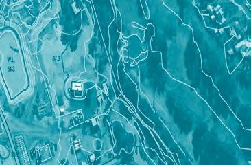
Landair assists their landfill clients to this end by maintaining a mapbased register of site infrastructure and in-ground services. They have formally trained surveyors with the skills to accurately detect and measure the position of buried utilities. The location and depths of the measured utilities are then added to a consolidated site data model containing all site services, infrastructure, topography and aerial imagery.
From this data model, hazard and in-ground utility maps can be created for block-mounting in public spaces or laminated for plant operators and sub-contractors. It is also possible to extract from the model 3D data that can be uploaded directly into excavators fitted with GPS receivers and threshold buffers set to warn when utility encroachment occurs.
Examples of information incorporated into site plans and plant tracking systems include in-ground electricity and communications cables, gas extraction pipe networks
The company has formally trained surveys to measure the position of buried utilities.

and water, drainage and leachate pipes. Buried asbestos locations, low powerline clearance zones, site traffic flow and hazardous areas are also incorporated.
Having a combined utility data file that is updated regularly allows ongoing analysis and asset protection across the many different landfill operations. It also inevitably leads to a higher standard of risk assessment for employees and fosters the duty of care principle from the top down. In an age where information is key, it’ s key to have all the information.
Anything but general cargo

You carry the essentials that make our world go round. Essentials that we often take for granted. Most people have no idea about the long hours spent on the highway. To arrive on time you need a vehicle that is anything but general. This is why we don’t do one-size-fits-all trucks. No. At Scania, we tailor solutions for the only business that matters. Yours.
High traction drums
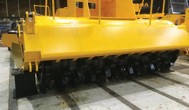
TANA HAS RELEASED A SPECIAL HIGH-DENSITY DRUM TO MAXIMISE CRUSHING FORCE ON A LANDFILL SITE INTO MORE UNIFORMLY SIZED PARTICLES.
Strong compactor teeth can be the difference between excellent or average traction and manoeuvrability on a landfill site, as they break, grind and compact their way through refuse efficiently.
The end result is increased efficiencies, allowing operators to increase profitability and focus their efforts on other crucial areas of the business.
To improve compaction rates with greater crushing force, Tana has released a special high-density drum with additional crushing teeth to further enhance its powerful BigFoot Drum design.
Available through exclusive supplier GCM Enviro, the new drum can be fitted to a new Tana E Series landfill compactor as an option and was recently released in Australia.
The new drums take traction and efficiency to a new level and increase the ability to compact waste in a shorter period.
The normal BigFoot drum and highdensity drum share the same external dimensions. Both drum models have crushing teeth in 11 rows. On the normal BigFoot drum there are 10 teeth per row while on the special drum there are 14 teeth per row. The special drum is roughly 500 kilograms heavier than the normal model.
The high-density drum has 44 spikes/ feet more than the regular drum, four on each 11 rows of the drum, ending up with a total number of crushing feet of 154 per drum. Jarmo Launiainen, Applications Manager, Compactors at Tana, says the more crushing teeth engaging the surface per drum rotation, the higher the compaction levels achievable.
“Most professionals support the claim that the key to compaction is reducing the incoming waste into more uniformly sized particles,” Jarmo explains.
“Large size differences may allow empty spaces between the waste items, even after compaction. This is why

a very high crushing force made by the compactor is needed to minimise this effect.”
Jarmo says the size, shape, structure and total number of the crushing teeth is important to ensuring a uniform compaction.
In a Tana E Series landfill compactor, the teeth are specifically designed
Fast Fact
Top features of Tana’s specialised drum: • Higher crushing force on feet tips: less feet tip contact at one time maximises the crushing force • High compaction rate in “feet pockets”: Tana has “pockets” between the feet for high waste compression
• Better traction: large side surface on feet gives better traction and more capacity and more teeth provide more traction • Big Foot for lower fuel consumption: shaped for better self-cleaning, thus lower fuel consumption. Less material pickup means better surface quality and less maintenance
• Scraper bars: shaped for better cleaning and lower fuel consumption
• Less maintenance required: the optimal shape for better function and longer lifetime • Strong crushing teeth features: produce maximum kneading effect on waste and laid out in a conical arrangement, maximising compaction.
for the most effective crushing and compaction. Measuring in at 200 millimetres (7.8 inches) in height, the compactors allow for thorough, highly wear-resistant, deep and aggressive penetration of every fresh waste layer. The teeth are designed in the shape of a pyramid, made of solid steel and are kept clean by a large number of adjustable scraper bars.
On the first pass, the Tana spreads and compacts the new waste layer on top of the previously compacted surface. The second pass concentrates on the crushing and thorough compaction of the waste. On the third pass, the pyramid shaped teeth and inverted conical spaces in between the teeth tie down the surface of the compaction path.
“Naturally, different waste types require a different number of passes to

The structure of Tana’s drums and teeth work to prevent homogenous waste fractions extruding under the wheels.

achieve the best results,” Jarmo says.
“All homogenous waste fractions have the tendency to extrude from underneath a conventional compactor’s wheels. The structure of Tana’s drums and teeth prevent this from happening.”
Jarmo says that there are two different types of pressure that work in tandem to achieve the optimum compaction: waste compacting and


waste escaping pressure.
“Compaction teeth are pressing the material deeper and the pan around the drum/wheel causes ground pressure together with the teeth. Ground pressure only compacts the top surface as the teeth compacts the waste deeper,” he says.
“Essentially, the static linear load increases with each pass.”


