NOV-DEC 2022 – ISSUE 199
RADIO BASED LIMITED SUPERVISION The latest initiative by Network Rail will supplement current train warning and protection systems. 30 YEARS OF QTS Rail Engineer meets founder Alan McLeish and tours QTS’s South Lanarkshire base. LIGHT RAIL SUMMIT Partnership was a key theme of September’s Light Rail Summit, held in Manchester. FOCUS FEATURES THE FUTURE ROLE OF RAIL: a strategic freight network
by rail engineers for rail engineers
www.railengineer.co.uk
ELECTRIFICATION & POWER LIGHT RAIL & METRO PERMANENT WAY & LINESIDE ASSETS
PHOTO: TEAMJACKSON


Join Railtex, the leading one-stop-shop event for the entire rail industry in the UK. Discover the latest technology in person and experience products and services from more than 180 different categories Connect with industry experts and make impactful business relationships Gain valuable insider knowledge and find out about the current trends and topics THE PLACE TO BE IN 2023! 9 – 11 MAY 2023 NEC, BIRMINGHAM Featuring: Conference Programme On-Track Display Area Recruitment Wall www.railtex.co.uk MORE INFORMATION: Organiser: All about the rail industry: Railway Civil Engineering - Rolling Stock - Track Design, Supply & Construction - Track & Infrastructure Maintenance - Safety & Security Systems - Electrical Products & Equipment - and much more!
Innovative GCRE construction competition
Radio Based Limited Supervision
Paul Darlington discusses RBLS - the latest initiative by Network Rail which will supplement current train warning and protection systems.
FFU crossings and sleepers
Sekisui’s fibre-reinforced foamed urethane (FFU) offers a weather-resistant alternative to the use of wood constructions on the railway.
An alternative to installing pantographs with 200mm clearances
Railway consultants and software specialists D/Gauge take a look at the future of gauging for electrification.
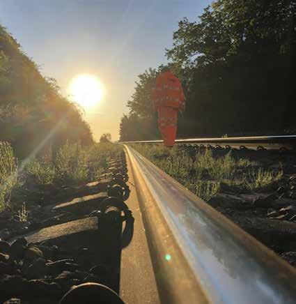
The impact of hot weather on British railway plain line track
Scorching temperatures are set to become the norm, so how will this impact the railway? Bob Hazel finds out.
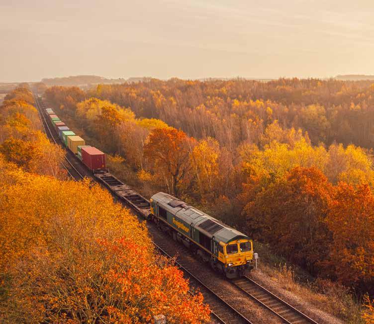
The future role of rail: a strategic freight network Peter Dearman argues for revitalising rail freight against a background of changing passenger travel patterns after the pandemic.
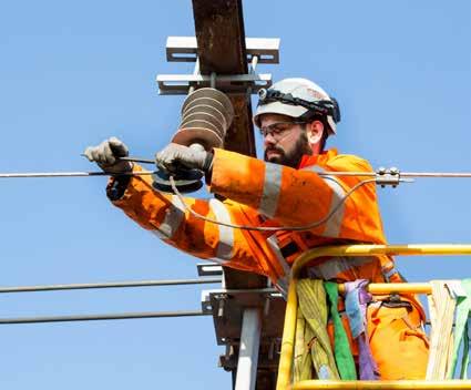
Test Before Touch for overhead line equipment A new standard formalises and improves on the existing guidance on the Test Before Touch Lifesaving Rule for OLE.
R.I.P. TDNS
Two years ago, Network Rail published its Traction Decarbonisation Network Strategy. Today it seems the Government has decided against it.
Static Frequency Converters: improving the 25kV A recent talk given to the IET Power Group focused on improving the quality and
Heritage Rail Association: safety, sustainability, and governance Malcolm Dobell visited the Heritage Rail Association’s Autumn Conference in Birmingham - here are his highlights.
18 66 CONTENTS 58 10| 18| 49| 52|
56|
30 years of QTS 58|
22|
30|
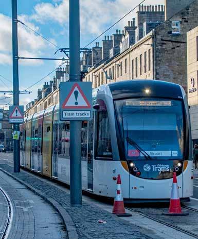
resilience of power feeding the railway. 34| With QTS celebrating its third decade, Rail Engineer met its founder, Alan McLeish, and toured its South Lanarkshire base. 34 62| Light Rail Summit September’s Light Rail Summit was held in Manchester, home of the country’s biggest tram system. Partnership was a key theme. 66| Newhaven tram extension almost complete Plans for an Edinburgh tram route from Haymarket station to Newhaven are close to realisation, after being unveiled in 1999. Upgrading London Underground’s Central Line tube stock London Underground is tackling reliability and obsolescence issues in its Central Line train stock. 40| 46| GCRE offers testers a welcome in the hillsides A hillside site in South Wales may provide the ideal location for the Global Centre of Rail Excellence (GCRE).
The Department for Business, Energy, and Industrial Strategy is funding a competition to encourage innovation in construction of the GCRE. 76| 70| 3 Rail Engineer | Issue 199 | Nov-Dec 2022
Electrification
deserves serious analysis
Electrification “…is an area that, perhaps above all others in rail strategy, is deserving of a serious and dispassionate analysis of its commercial, economic, and environmental benefits.” These words were written 15 years ago in a letter to the DfT signed by Iain Coucher, Network Rail’s CEO and Adrian Shooter, Chairman of the Association of Train Operating Companies.
Their succinct three-page letter explained why electrification was required, saying, for instance, that: “using diesel trains as minipower plants to generate tractive power is both inefficient and wasteful”. It expressed their concern about the lack of electrification in a 2007 Government White Paper and stated: “We believe this is wrong”. It’s doubtful that such a direct view could be expressed today.
A recent equivalent document is Network Rail’s Traction Decarbonisation Network Strategy (TDNS) which, in 2020, recommended an electrification rolling programme of 13,000 single track kilometres. It detailed the economic case for this programme and how it would benefit passengers, freight users, and the wider economy.
TDNS was used to inform the Department for Transport’s (DfT) plan ‘Decarbonising Transport – A better, greener Britain.’ This committed to a net zero rail network by 2050 with “an ambitious, sustainable,
cost-effective programme of electrification guided by TDNS”. However, the truth was revealed in recent statements by Network Rail’s Andrew Haines and the Great British Railways Transition Team (GBRTT) that the Treasury’s 2021 Comprehensive Spending Review has made TDNS unaffordable. GBRTT is therefore developing plans to substantially increase the number of diesel bi-mode trains and eventually deliver about half the electrification recommended by TDNS. This may give a net zero railway by 2070.
Hence this Treasury decision has denied GBRTT the opportunity to take a wholesystem view to define a railway traction policy which offers the best performance at lowest whole life cost. This is ironic as it is this very lack of whole-systems thinking that GBR was set up to eliminate.
As our report ‘R.I.P. TNDS’ makes clear, it is the lack of such strategic thinking that has, following the recent procurement of over 7,000 vehicles, wasted billions from the scrapping of serviceable rolling stock including hundreds of electric units with no wires to run under after electrification schemes were cancelled. Current GBRTT plans are to increase the fleet of diesel bi-modes (which are both underpowered diesels and overweight electrics). This will saddle industry with additional running costs for many years and do nothing for freight in the short-term.
This is in contrast to the Scottish Government’s Rail Services Decarbonisation Plan for net-zero carbon rail traction by 2035 through a large-scale electrification programme. The view in Scotland is that this will provide a better railway and enable its ageing diesel fleet to be replaced with electric trains that are cheaper to buy and operate. In essence, Scotland feels it cannot afford not to electrify its railways. The Scottish view mirrors that of most of Europe where electrification is regarded as a profitable investment.
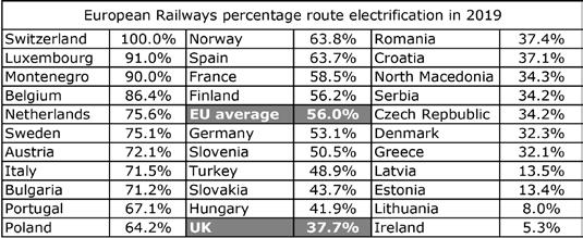
Britain ranks 21st out of 32 in the European electrification league table and must be one of the few countries in the world that operates an intense service of diesel-powered 100mph trains. As a result, UK rail has one of the worst rail carbon records. For example, only 5% of the energy for its freight trains is from electric traction.
This also means that Britain’s freight locomotives are only half as powerful as those on the continent. Revitalising freight is the theme of a feature by our guest writer, PWI President, Peter Dearman who considers that railway unduly prioritises passenger trains above freight and that recognising the importance of rail freight will secure the railway’s future. He stresses the importance of freight modal shift and the need for gauge clearance for container traffic.

4 EDITORIAL EDITORIAL
Rail Engineer | Issue 199 | Nov-Dec 2022
Much is being done to reduce the cost of electrification. Clive Kessell describes one such innovation, the use of Static Frequency Converters which enables the OLE to be fed by the distribution network operator. We also describe the new ‘test before touch’ process to improve the safety of those adjacent to 25kV equipment.
Malcolm Dobell reports on the wideranging Light Rail Summit which featured presentations from the Light Rail Safety and Standards Board and from UK Tram on its Light Rail Strategy which supports the development of new schemes. Edinburgh’s Newhaven tram extension, on which we also report, demonstrates the popularity of trams as this was approved a few years after the completion of the much-troubled original Edinburgh tram project when trams were a toxic subject in the city. The popularity of London’s tube trains is such that 30-year-old Central line tube trains have now accumulated over 4 million miles in service. We describe the impressive upgrade work being done to extend the life of these units.
Although it is not an obvious location, we explain why the top of a Welsh mountain is an ideal site for the test track being built as part of the Global Centre for Rail Excellence (GCRE) and why this facility is likely to become a leading research hub. The centre’s two test loops will be able to test trains, infrastructure, and systems. Radio Based Limited Supervision
(RBLS) is one such system. Paul Darlington describes how this is being developed to eliminate the residual train protection risk between TPWS and ETCS as the digital signalling roll-out programme now envisages TPWS being operational in 40 years’ time.

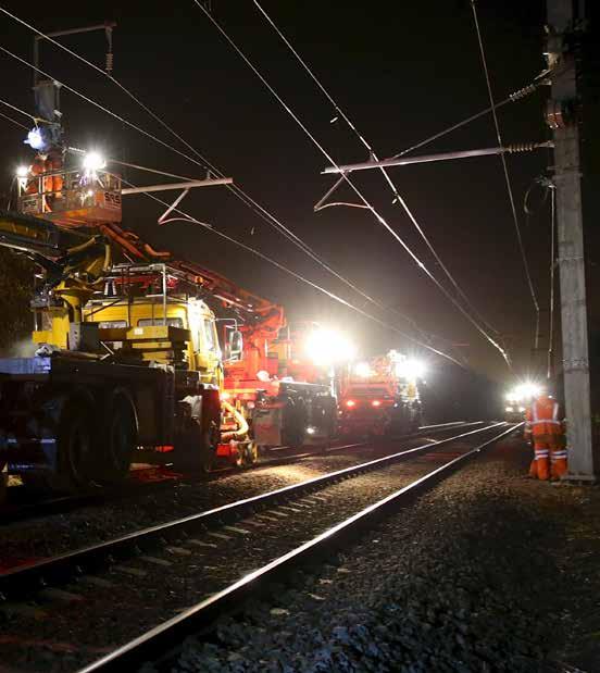
The all-time high UK temperatures this summer generated record forces within the rails as they tried to expand. Bob Hazel’s feature on how track is designed and maintained to withstand these forces is therefore a topical read.
This year’s Heritage Rail Association’s conference focused on safety and sustainability. With a largely volunteer workforce and old assets, heritage railways have different challenges than the national network. Yet there is much that both sectors can learn from each other. This is a theme to which we will return.
Finally, Rail Engineer is saddened to learn that Vivarail has appointed administrators. We record and celebrate its achievements. Our thoughts are with those who worked for the company.
Editor
David Shirres
david.shirres@railengineer.co.uk

Production Editor
Matt Atkins matt@rail-media.com
Production and design Adam O’Connor adam@rail-media.com
Engineering writers
bob.hazell@railengineer.co.uk bob.wright@railengineer.co.uk clive.kessell@railengineer.co.uk collin.carr@railengineer.co.uk david.fenner@railengineer.co.uk graeme.bickerdike@railengineer.co.uk malcolm.dobell@railengineer.co.uk mark.phillips@railengineer.co.uk paul.darlington@railengineer.co.uk peter.stanton@railengineer.co.uk stuart.marsh@railengineer.co.uk
Advertising
Asif Ahmed asif@rail-media.com Chris Davies chris@rail-media.com Craig Smith craig@rail-media.com Tiffany Frost tiffany@rail-media.com

Rail Engineer
Rail Media House, Samson Road, Coalville Leicestershire, LE67 3FP, UK. Switchboard: 01530 816 444 Website: www.railengineer.co.uk
Rail Engineer Videos
http://rail.media/REYouTube
Editorial copy to Email: news@rail-media.com
Free controlled circulation Email: subscribe@rail-media.com
The small print
Rail Engineer is published by RailStaff Publications Limited and printed by PCP Ltd.
© All rights reserved. No part of this magazine may be reproduced in any form without the prior written permission of the copyright owners.
Part of:

® www.rail-media.com THE TEAM
DAVID SHIRRES
RAIL ENGINEER EDITOR
5 Rail Engineer | Issue 199 | Nov-Dec 2022
Vivarail, an ode to innovation
In late November it was announced that Vivarail, manufacturer of battery and hybrid trains, had filed a Notice of Intention to appoint administrators. A notice posted on social media read: Established in 2013 by Adrian Shooter CBE, Vivarail has spent the last nine years investigating, trialling, developing, and testing battery technology for rail Its work has included the development of its own patented Fast Charge system.
Steve McBride, Managing Director said: “The board and I have worked incredibly hard to secure new investment in recent months, and although we have been encouraged by the level of interest, time is now against us to allow potential investors to step in. Combined with slow market conditions and delays in reaching certain key commercial arrangements we have had no choice but to file a notice of intention to appoint administrators with the courts.”
The company’s management, board of directors, and advisors are working hard to find a solution, consulting with customers and other stakeholders to try and drive the business forwards. However, if they are unable to deliver a rescue package, the company will enter administration.
This has all come about because the company decided in early 2022 to make progress without further funding from its ‘sole investment partner’.

Sadly, this notice was followed on 1 December by another message from Vivarail’s managing director confirming that he had handed the keys of the business to Grant Thornton, the appointed administrator.
In the meantime, we record and celebrate what Vivarail has achieved. Since 2013. It has:
» Modified its D stock to comply with the level crossing collision requirements of EN 15227. These trains have a separate body on a strong underframe with crashworthiness appropriate for metro standards of the mid-1970s.
» Developed quickly removeable diesel generator rafts based on automotive diesel engines first employed on three two-car units refurbished for London Northwestern Railway’s Marston Vale line. Unusually, after a fire in one of these rafts it published its own internal investigation report - a lesson in transparency.
» Demonstrated a battery powered version at Rail Live in 2018 using some batteries upcycled from the Class 379 demonstration.
» Made available a D stock vehicle for SET Ltd to experiment with steerable bogies based on wheel mounted bogies.
» Developed a diesel-battery hybrid system again based on the interchangeable raft system, delivering five three-car units to Transport for Wales for use on the Wrexham to Bidston line. These have been delayed by Covid and what was described as ‘a thermal event’.
» Delivered five two-car third-rail DC units to the SWR’s Island line on the Isle of Wight. These are fitted with three phase AC drives.
» Shipped two two-car battery powered units to the USA for Henry Posner III’s Railway Development Corporation to demonstrate the concept of ‘pop-up metro’ on existing lightly used freight lines.

» Demonstrated a three-car battery powered unit at COP26 which carried delegates on demonstration runs from Glasgow Central to Barrhead. In the run up to the event there was a demonstration run over the iconic Forth Bridge.
» Developed a patented fast charging system using two short conductor sections mounted in the four foot which are only energised when the train is over them and the shoes are in contact.
» Developed plans to trial the COP26 unit in passenger service operation on the West Ealing - Greenford line in early 2023. This unit and its fast-charging system was recently unveiled at Bletchley depot.
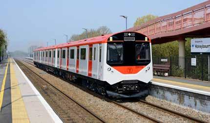
» Refurbished all these trains to a high standard blending original D stock features such as longitudinal seats together with features never seen on these trains such as universal access toilets, inter-car gangways, transverse, high backed seats, and air conditioning.
Having travelled on both the Marston Vale and Cop26 units, your writer was consistently amazed at the quality of the completed units. Even the diesel versions were reasonably quiet and the ride on secondary lines was perfectly acceptable. In addition, delivering universal toilets on trains never intended to have toilets at all was a great achievement.
For the sake of all the people who have contributed to Vivarail’s technical developments, Rail Engineer hopes that there will be some good news soon.
All about people people working in public transport...people like you! Health, welfare and financial help in times of need, hardship and distress. £1.25 a week covers you, your live-in partner and dependent children. 0300 333 2000 | help@tbf.org.uk | www.tbf.org.uk Transport Benevolent Fund CIO, known as TBF, is a registered charity in England and Wales, 1160901, and Scotland, SC047016. less than 20p a day
NOTICES 6 Rail Engineer | Issue 199 | Nov-Dec 2022
MALCOLM DOBELL
Total

Visit totalrailsolutions.co.uk or call 01962 711642 to find out more
total rail Service
Rail Solutions now offers a unique concierge Meet and Greet team further improving your quality of service.
• Ensuring the plant, equipment and people you need is where it needs to be, when it needs to be
• Meaning you and the kit you have hired is ready to go to work
Improving efficiency and effectiveness whilst delivering a positive customer experience, every time. scan this Visit totalrailsolutions.co.uk or call 01962 711642 to find out more Watch the new meet and greet team at work
HS2 smashes carbon target
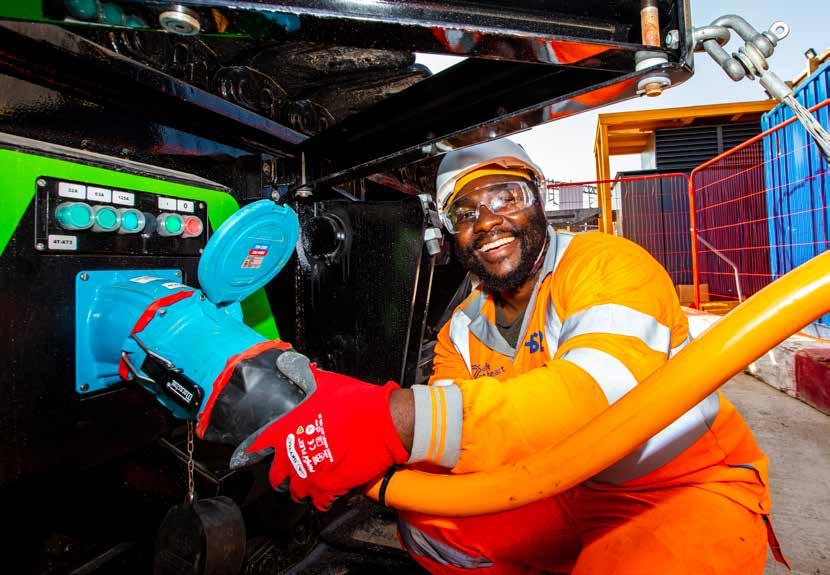
Earlier this year, the Canterbury Road Vent Shaft in South Kilburn, managed by Skanska Costain STRABAG joint venture (SCS JV), became HS2’s first diesel-free site. Now the SCS-managed Euston Approaches and Victoria Road Crossover Box sites have also achieved diesel-free status.
Align - a joint venture formed of Bouygues Travaux Publics, Sir Robert McAlpine, and VolkerFitzpatrick - has also announced that seven of its 14 sites are now diesel-free. These include five vent shaft sites along the route of the 10-mile Chiltern tunnels in Buckinghamshire, and two sites involved in the construction of the Colne Valley Viaduct.
After achieving the first diesel-free site on the HS2 project in May, SCS JV aims to be fully diesel-free by the end of 2023 using a combination of mains electricity, fully electric machines, renewable energy, and biofuels.
Its first site - Canterbury Road Vent Shaft in South Kilburn, is connected to mains electricity on a 100% renewable energy tariff. This powers one of the UK’s first 160 tonne emissions-free fully electric crawler crane, as well as other electric plant such as electric compressors, with the rest of the machinery using sustainably sourced biofuels (HVO) as a direct replacement for diesel.
At HS2’s Euston Approaches, also managed by SCS JV, the world’s first all-electric, high-capacity BAUER drilling rig cuts 1,200kg of CO2 per day adding momentum to HS2’s carboncutting ambitions.
SCS’s third diesel-free site, Victoria Road Crossover Box has a mains electricity connection, is deploying electric equipment, and is making use of sustainably sourced biofuels (HVO). The site recently successfully completed trials for two GeoPura 250kVA hydrogen power units (HPUs) – cutting carbon and improving air quality for workers and the local community.
James Richardson, managing director of SCS JV said: “We are proud to be pioneers of diesel-free construction, and we are committed to seeking out and adopting new technology and ways of working to eliminate diesel on construction sites. This all starts with a shift in mindset and a belief that our industry can have a cleaner, greener future."
Along with seven of Align’s 14 sites becoming diesel-free, its 136 acre Chiltern Tunnels South Portal - HS2’s largest construction site - is also well on its way to becoming 100% diesel-free next year. On that site, over 120 pieces of plant including dumpers, tractors, excavators, pumps and crushers are all operating using HVO.
In addition, there’s a range of fully electric plant such as telehandlers and excavators, renewable energy sources such as solar, and site safety gates powered by hydrogen, all reducing carbon impacts and improving local air quality.
“Our strategy is to move to diesel-free operations across all of our construction sites, so we’re thrilled to say that half of our sites are now diesel-free,” said Adetunji Lawal, Align JV’s Carbon and Energy Manager.
“In addition, on our extensive Chiltern Tunnel South Portal site, all of the earthworks activities that represent 70% of our fuel consumption are now 100% diesel free. We estimate that Align will be able to deliver carbon savings that equate to 80,000 tonnes by the end of the project, supporting HS2’s zero carbon ambitions.”
To explain how the project will continue its mission to achieve 100% diesel-free construction sites by 2029, HS2 has published its ‘Diesel-free Plan: Building a net zero future’. It details HS2's journey to diesel-free construction sites and a new ratings system which ranks all sites from diamond to bronze, so progress can be mapped over the next few years.
“Our ambitious goal is to eliminate diesel on all HS2 construction sites by 2029,” said Andrea Davidson, HS2 Ltd’s Head of Environmental Sciences. “One of the first targets in our Net Zero Carbon Plan was to achieve one diesel-free site during 2022, so we’re thrilled to see 10 sites already reaching this major milestone supported through the hard work from our on-site teams.
“Our ‘Diesel-free Plan: Building a net zero future’ explains how we will reach our goal by improving efficiencies, switching to cleaner fuels, using renewable power such as solar, using the latest cleanest and fully-electric machinery, and continuing to collaborate with the wider industry to set new standards and push the boundaries of green innovation.”
NOTICES 8 Rail Engineer | Issue 199 | Nov-Dec 2022
HS2 has announced that 10 of its worksites are now diesel-free, surpassing the project’s target of one diesel-free site in 2022.
dirty truth about rail cleaning...

63% of cleaners were struggling to make ends meet BEFORE the cost of living crisis
Rising prices mean that a cleaner on the National Minimum Wage would need a £2,000 pay rise to have the same spending power as last year
Cleaners get no company sick pay
69% of cleaners say they have gone into work sick because they can’t afford not to work
Cleaners get no travel facilities
The number of cleaners has been cut leaving people overworked and underpaid.
Britain’s Largest Specialist Transport Union Protecting our members’ interests is our priority Join us today rmt.org.uk FREEPHONE 0800 376 3706 RMTunion IT’S TIME FOR JUSTICE for CLEANERS More cleaners than ever before are balloting for industrial action and taking strike action. If you’re NOT a member JOIN NOW!
•
•
WE DEMAND... • A pay rise to £15 an hour • A proper sick pay scheme • Travel provision • Proper pension provision • An end to outsourcing and profiteering on cleaning.
The
•
•
•
•
THE FUTURE ROLE OF RAIL: a strategic freight network
PETER DEARMAN


In this feature I set out the argument for revitalising rail freight against a background of changing passenger travel patterns after the pandemic. Whilst the end of lockdowns and opening up of the economy has seen increased ridership, the patterns of travel have changed, and overall demand has remained suppressed. It is clear that significant and permanent changes to railway services will inevitably follow with timetables reduced compared to pre-pandemic.

Furthermore, the relevance of the railway from the mid-21st century onwards is not guaranteed. My view is that the railway unduly prioritises passenger trains above freight. A container train conveying £20 million of time-sensitive goods is surely more important than a lightly-loaded passenger service.
Hence, a rebalancing of those priorities is needed to recognise the importance of rail freight and so secure the railway’s future and its ability to contribute to the economic and ecological wellbeing of society at large.
60 years of reshaped railway
In 1963 Dr Beeching published his report, ‘The Reshaping of British Railways’. Whatever might be thought of the man, it is undeniable that by that time the railway had to change.

His report is remembered for its proposed large-scale closures. Yet Beeching arguably saved the railways as his report laid the foundations of the modern railway by proposing container trains
and the inter-city passenger network. Beeching recognised that railways have high fixed costs that offered great benefits when intensively used.
PHOTO: TEAMJACKSON
Rail Engineer | Issue 199 | Nov-Dec 2022 10 ELECTRIFICATION & POWER
At that time road haulage was an economic growth area and the motorway network was being built to encourage this modal shift away from rail. By 1963, parts of the M1, M5, and M6 had opened and there were 200 miles of motorway. Now there is a motorway network of 2,300 miles. Last year, the freight carried by HGVs amounted to 154 billion tonne km which compares with 18 billion tonne km carried by rail.
In the early sixties, the large workforce, wagon fleet, and rail network provided for goods traffic could not be sustained. Hence, over six decades our railways have become increasingly passenger
and offers hope for the future, but the hurdles that have been crossed, and I suspect those yet to come, do not speak of a balanced 21st century approach.
Decarbonising freight
In 2019 the UK became the first country to make a legal commitment to net zero greenhouse gas (GHG) emission by 2050. Although the UK has reduced its GHG emission by 50% since 1990, there has been little change to transport emissions which are around 500 million tonnes CO2e each year, including international aviation and shipping. In 2017, rail traction and HGVs accounted for respectively 2 and 21 million tonnes CO2e.
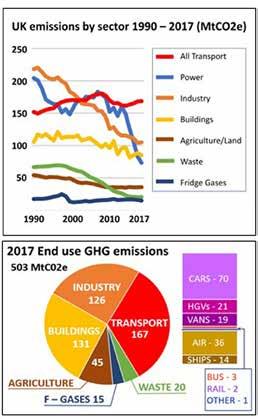
Rail has electric trains which is currently the only technology offering low carbon high powered transport. This is one reason why Network Rail’s Traction Decarbonisation Network Strategy (TDNS) recommended a large-scale rolling programme of electrification. Yet, other than in Scotland, there seems to be no government support for this.
Other modes of transport need to be weaned off petroleum if they are be decarbonised. This is a particular challenge for high-powered transport such as HGVs. If these are to be decarbonised, a huge infrastructure investment is required, be it hydrogen fuelling stations, heavy-powered battery chargers with upgraded distribution networks, or overhead electrification.
It will be some years before the optimum HGV decarbonisation solution is determined and many years after that before that necessary infrastructure is provided.
Modal shift
centric. Our railways in general no longer seek to provide for mixed traffic during the day, and the conflict with maintenance access constrains freight operation at night. Last year, freight trains travelling 8 million miles had to be fitted amongst 473 million miles of passenger train journeys.
As a result, from the freight industry perspective, the transport infrastructure investment has become skewed towards roads with rail investment largely prioritised towards passengers to improve journey time and increase capacity.
In November 2021, the Integrated Rail Plan (IRP) for the North and Midlands devoted just one page to rail freight for which it had no proposals. It cancelled two proposed high-speed lines: HS2’s eastern leg and Northern Powerhouse Rail’s proposed new line from Manchester to Leeds via Bradford which would have created extra freight capacity on the existing network.
A positive aspect of the IRP is that the TransPennine Route Upgrade (TRU) is now moving towards inclusion for freight by clearing the route to W12 gauge. That is cause for some comfort,
Hence, a large shift from road to rail is particularly important. To be clear I make this argument from an economic as well as ecological standpoint. In the short term, this is the only way of significantly decarbonising the nation’s freight transport, especially container traffic which can easily be moved from road to rail. A 10% shift of road traffic to rail would save 3.6 million tonnes CO2e per year which is twice the railway traction emissions. Similar savings are to be had if more passengers shift to rail.
The Chartered Institute of Logistics and Transport (CILT) estimates that around 38% of HGV container traffic may be suitable for modal shift to rail. This includes almost all very long road hauls over 300km, a significant proportion in the 200-300km range, and some heavy bulk commodities and construction materials in the 100-200km range. This assumes that battery HGVs with a range of 200km will be used for shorter distance local and regional hauls.
The Government’s Transport Decarbonisation Plan (TDP) states that we will “support and encourage modal shift of freight to more sustainable alternatives such as rail.” It explains
Rail Engineer | Issue 199 | Nov-Dec 2022 11 ELECTRIFICATION & POWER
how HS2, and TRU will provide the required additional capacity, yet much more needs to be done. Of the 35 schemes in the Rail National Enhancements Pipeline, almost all relate to passenger services.
Furthermore, current HS2 plans will create bottlenecks. North of Crewe, for example, enhanced ‘classic compatible’ passenger services will compete with railfreight for the available capacity.
Deep sea and continental European container traffic offers significant rail freight growth potential and ports will enthusiastically switch to rail if the railway can adapt to provide the capacity to accommodate this pent-up demand.
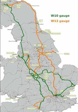
Much of this potential traffic cannot be accepted as the rail freight network is seriously constrained with significant gaps in routes cleared to W10 or W12 gauge. For example, there is no route for 2.5-metre-wide containers, from the Channel Tunnel to north of London and no East-West route between Lichfield and Edinburgh.
Freight gauging
Gauge clearances through overline bridges and particularly tunnels are costly. Whilst the industry has relatively clear gauge categorisation in place, at the extremes, those categorisations are far from economically prudent. Hence, to minimise the cost and disruption, gauge dimensions need to be clearly defined.
Early in the post privatised railway it became evident that loading gauge definition was problematic. There was widespread confusion about matching vehicle and infrastructure gauges with gauge boards and polystyrene blocks commonly used to verify clearances. After much deliberation the “W” gauges were defined.
The railway’s dominant gauge is W6a for which most main line passenger trains are compliant. Bulk freight trains, certainly of modern construction, are compliant to W6a and thus need no great attention.
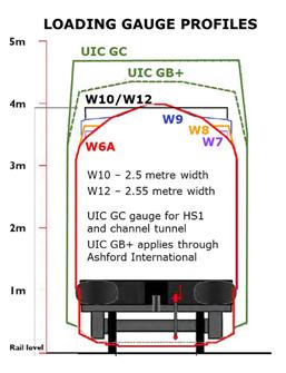
Containers, including swap body traffic, are a particular problem as they have no single set of dimensions. Furthermore, these are somewhat eccentrically defined with height and length being in feet and inches and width in metres. Containers by themselves do not entirely define the loading gauge as the vehicle deck, suspension and bogie centres are also highly influential. Hence gauging container traffic is a complex issue and leads to a tendency to safe option of adopting the largest standard gauge, W12. This is therefore a lazy approach which saddles freight route clearance business cases with costs for trains that will never operate on the route.
An alternative approach is to adopt probabilistic gauging. All the W gauges consider the vehicle size, shape, and extremes of dynamic movement. Defining the W gauge therefore takes the extreme value of every infrastructure and train tolerance to define the passing envelope. In contrast, probabilistic gauging applies a statistical

Rail Engineer | Issue 199 | Nov-Dec 2022 12 ELECTRIFICATION & POWER
Much HGV traffic needs to shift to rail.
approach to establish a probability of position for particular vehicles and so minimises the cost of route clearance for container traffic.
Such probabilistic analysis can significantly reduce the cost of gauge clearing tunnels and bridges. This technique is not a new or speculative science and is used in the aviation, atomic power, oil, and gas industries. However, despite having the technique being well developed, a curiously luddite attitude prevails in rail. That must change.
An update of the freight wagon standards is also required to avoid future wagon fleets breaching the gauge as determined by the combination of container and wagon sizes. Such specifications must define the maximum dimensional limits for deck height, suspension, and dynamic movement of today’s fleets and future fleets. Whole industry commitment for this, including RSSB, is essential.
Freight electrification
Electrification particularly benefits rail freight as electric locomotives are typically twice as powerful as diesel locomotives. This is because the power of an electric locomotive is limited only by the current it can draw from the wire, whereas a diesel locomotive’s power is limited by the available space for its engine and cooler group. Hence, a Class 92 electric locomotive can deliver 5,000kW at the rail whilst, Britain’s most powerful diesel locomotive, the Class 70 can only deliver 2,500kW. Whilst this is sufficient to haul main-line container trains, performance is limited when climbing steep gradients or accelerating to line speed.
Bi-mode locomotives have the flexibility to take power from the wires or diesel fuel. Yet they have limited spaced for an engine due to their electric traction equipment. It is understood that the recently ordered Class 99 bi-mode locomotives will only be able to deliver 1,600kW at the rail.
Electric locomotives can therefore haul heavier, longer, faster trains as well as increasing capacity by reducing the performance differential between
freight and passenger trains. Currently, electricity provides only 4% of the energy for UK rail freight compared with 56% in continental Europe.
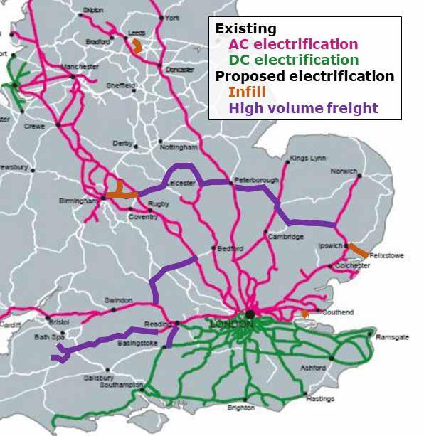
The CILT’s rail freight forum has concluded that 70% of rail freight could be electrically hauled if 700 single track kilometres (stk) of key freight routes were electrified. This is 5% of the TDNS’s proposed programme and would enable electric freight haulage of typically 28 x 3,000 tonne freight trains per day from the Mendip Quarries to London and container trains from Felixstowe (56 trains/day) and Southampton (48 trains/day) to Birmingham for distribution to the many West Midland distribution warehouses. It also includes a mere 2.5 stk to connect the port of London Gateway to the electrified network.
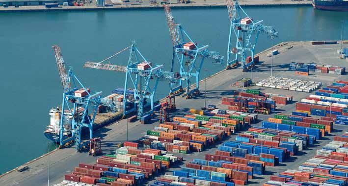
The ports of Felixstowe, Southampton, and London handle over 70% of UK shipping container traffic yet none have an electrified rail connection.
Rail Engineer | Issue 199 | Nov-Dec 2022 13 ELECTRIFICATION & POWER
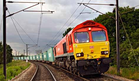
Many freight trains are diesel hauled under electrified wires because lines to container ports are not electrified.
This approach is recognised and supported by the government’s TDP which states that it will purse “infill electrification which could allow a significant rise in the electric haulage of freight” and that “by 2050 all rail freight will be net zero.” However, these commitments are in doubt as recent statements by Network Rail and the GBR transition team indicate that the Treasury considers that TDNS’s large-scale electrification programme is unaffordable.
Prioritising freight
Mixing freight and passenger traffic on a busy railway is a significant operational challenge for which loops that enable passenger trains to ‘overtake’ freight trains are part of the solution. To adequately cater for this mixed traffic these loops need to be long enough to accommodate the maximum freight train length of 775 metres and their points need to have a reasonable entry/exit speed.
Between Preston and Carlisle, there are eight loops in each direction. Of these 16 loops only four can accommodate 775-metre freight trains. Turn out speeds through their 32 sets of points range from 10mph to 40mph. Half have a turn out
speed of 20mph or less. The last thing a freight train driver hauling a 1,500 train at 75mph wants to see is a signal diverting his train over a 15mph set of points. This eats line capacity as the time taken to decelerate this train, pass the entire train over both sets of points at this speed and then accelerate back to 75mph is considerable, especially if the train is going up a gradient and is diesel hauled.
This also begs the question of whether freight trains should be looped to allow passenger trains to pass. It is not unreasonable to suggest that a heavily intermodal freight train should be considered to have more economic value than a lightly loaded passenger service.
Currently, each train has a four-digit train headcode in which the first digit denotes class and priority. Generally, classes 1 and 2 are express and ordinary passenger trains, 3 is used for parcels trains, 4 for 75mph freight and the remainder for freight of progressively lower speeds. This system was introduced in 1962 and is essentially unchanged after 60 years.
With much changed since this system was introduced, a review is needed to take account of the train’s economic, environmental, and social value. Average speed also needs to be considered. For example, a 75mph container train averages around 70mph on the southern section of the West Coast Main Line, whilst a stopping passenger train with a maximum speed of 110mph might only average 40mph.
A strategic plan
Rail freight companies and ports cannot on their own bring about the required modal shift to rail. Without gauge, traffic can’t be moved, yet the lack of current traffic makes the business case for intervention more difficult.
Without a strategic plan supported by the whole rail industry, progress will continue to be painful and slow with decision making repeatedly dragging through first principles. Slow progress
PHOTO: NETWORK RAIL
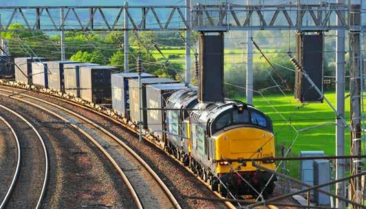
Freight train waits in a loop.
Rail Engineer | Issue 199 | Nov-Dec 2022 14 ELECTRIFICATION & POWER
PHOTO: NETWORK RAIL
and indecision will encourage investment in HGV decarbonisation experimentation. Yet no amount of innovation can change the fact that steel wheels on steel rails will always be many times more energy efficient than rubber-tyred HGVs.
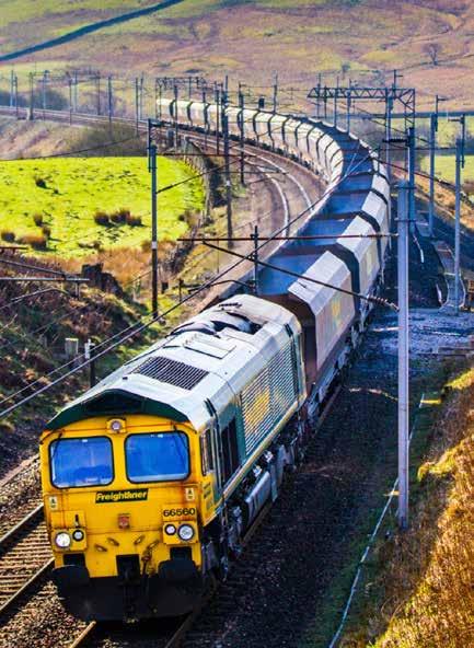
To achieve this freight routes need to be prioritised in three categories. The first two are infill electrification routes and those that carry a high volume of freight traffic which are proposed electrification priorities as previously shown. The third category are the remaining lines of the core freight network which are:
» Church Fenton-Toton-Kings Norton,
» Bromsgrove-Westerleigh,
» Margam-Cardiff,
» Westbury-Southampton,
» Basingtoke-Laverstock,
» Westbury-Chippenham,
» Dore-Stalybridge-Stockport,
» Tunstead-Chinley,
» Swinton-Immingham,
» Northallerton-Redcar,
» Darlington-Eaglescliffe
An important component of the strategy must be the prioritisation of the required work to achieve the key priority maximising the shift of container traffic from road to rail. Freight traffic on rail, regardless of traction type, is better than diesel road haulage. Hence there should be no delay in facilitating that modal shift. The first
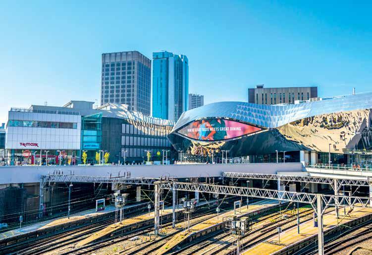
Latest rail video. Daily email update. UK rail news as it happens. Over 15,000 rail articles. Rail Engineer | Issue 199 | Nov-Dec 2022 15 ELECTRIFICATION & POWER
www.railuk.com
priority should therefore be gauge clearance of the strategic freight network by the most economic means, including probabilistic gauging.
I believe that making the case for electrifying the whole strategic network is an unnecessary complication which damages the case for the good by pursuing the perfect, a folly not uncommon in rail projects over the past two decades.
Opening routes to container traffic flows will encourage the Rail Freight sector to progress locomotive fleet renewal with diesel bi-mode locomotives possibly fuelled by hydrated Vegetable oil (HVO) that can maximise the use of electric traction when under the wires. In service, those locomotives will allow unrestrained progress with volume growth to complete the modal shift. But unless the strategic plan is clear, the Rail Freight industry has no reason to specify and buy such locomotives.
As the plan rolls out, the benefits of modal shift will reduce road haulage and consolidate rail traffic volume growth to allow the business case for largescale electrification to be developed.
The way forward
The totality of the plan will need to encompass many aspects not touched upon here. The Strategic Freight Network must connect the ports to distribution terminals where containers transfer between trains and electric HGV lorries for final distribution. Many of those distribution terminal locations already exist, but some are sub-optimal in terms of rail traffic planning and road connectivity. Hence new and relocated terminals will be required.
Considering the range of issues involved and developing a consensus within the rail industry, then driving the vision forward requires single minded leadership. The political turmoil of 2022 has provoked speculation over the commitment to the creation of Great British Railways (GBR), especially with the postponement of its enabling legislation. Cancellation of the GBR plan is likely to bring a prolonged period of uncertainty and planning blight. Perhaps that is the objective from the Treasury’s perspective.
Views about GBR vary, some are enthusiastic supporters others less so. Yet GBR represents an opportunity to engage all in the industry in moving
Summary
Some may be surprised to find me seeing electrification as a second phase objective. I have three reasons for recommending this approach:
1. The pressing need is to get freight off the roads on to rail. Sorting out the gauge largely achieves this and should be the focus.
2. Electrification works have been deeply flawed over recent control periods. Whilst there are signs of a willingness to address this, much remains to be done. Until good programme discipline, much reduced costs and improved cost control can be demonstrated, electrification estimates will have high costs. This will damage rather than help the case for both freight and electrification.
3. The separation of works as individual programmes will prevent the development of over-scoped route modernisation models becoming a block to rapid achievement of the modal shift.
In summary, I believe the rail industry has the opportunity to produce a plan for a Strategic Freight Network for which early industry wide commitment is needed. This plan must:
» Deliberately reject the industry enthusiasm to turn schemes into route modernisation programmes; it is better to tackle works incrementally over time.
» Concentrate on maximising the modal shift of container traffic from the ports onto rail by prioritising gauge clearance work to open routes and allowing diesel locomotive operation to aggressively drive the modal shift.
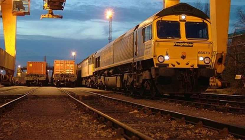
» Base gauge works on probabilistic gauging, allowing for future electrification to minimise the cost.
» Co-ordinate the specification of locomotives and container wagons as part of the strategic plan. If this is done, the business case and roll out of electrification will follow as freight traffic growth consolidates.
forward with a strategic plan for freight and other changes the railway and the nation desperately needs.
Rail Engineer | Issue 199 | Nov-Dec 2022 16 ELECTRIFICATION & POWER
Peter Dearman is President of the Permanent Way Institution and is indebted to Julian Worth for his help in preparing this article.

www.dgauge.co.uk Experts for all your gauging needs Rolling Stock | Infrastructure | Electrification Unlock the power of freight Think outside the W12 box Move larger loads to more places using better gauging. D/Gauge can help you: • Find shorter or alternative routes for existing services • Move large loads or containers on existing routes • Unlock new routes for new services All done using dynamic freight models with specific combinations of wagons, containers and loads. Get in touch Email: mandeep.singh@dgauge.co.uk Call us: +44 (0)7566 793 420 Our library of common wagons may make your freight gauging quicker and more cost effective than you think! Tried and tested in the Freight community. We’re trusted suppliers to Greenbrier, VTG, GBRF, DB Cargo, Freightliner and more.
Test Before Touch

for overhead line equipment
PAUL DARLINGTON

An essential requirement of any electrical system is a means of safely and efficiently disconnecting the system to allow maintenance work to take place, and not to create danger and the risk of injury.
Regulation 4 of The Electricity at Work Regulations 1989, requires that every work activity, including maintenance of a system and work near a system, shall be carried out in such a manner as not to give rise, so far as is reasonably practicable, to danger and the risk of injury. Regulation 14c also requires that no person shall be engaged in any work activity on or so near any live conductor where danger may arise unless suitable precautions are taken to prevent injury.
As a result of too many incidents of workers suffering life changing injuries due to inadvertent contact with Live Overhead Line Equipment (OLE), and the Office of Rail and Road (ORR) issuing an improvement notice (for non-compliance with regulation 14c), Network Rail are introducing a new standard “Test Before Touch for Overhead Line EquipmentNR/L3/ELP/27720”.
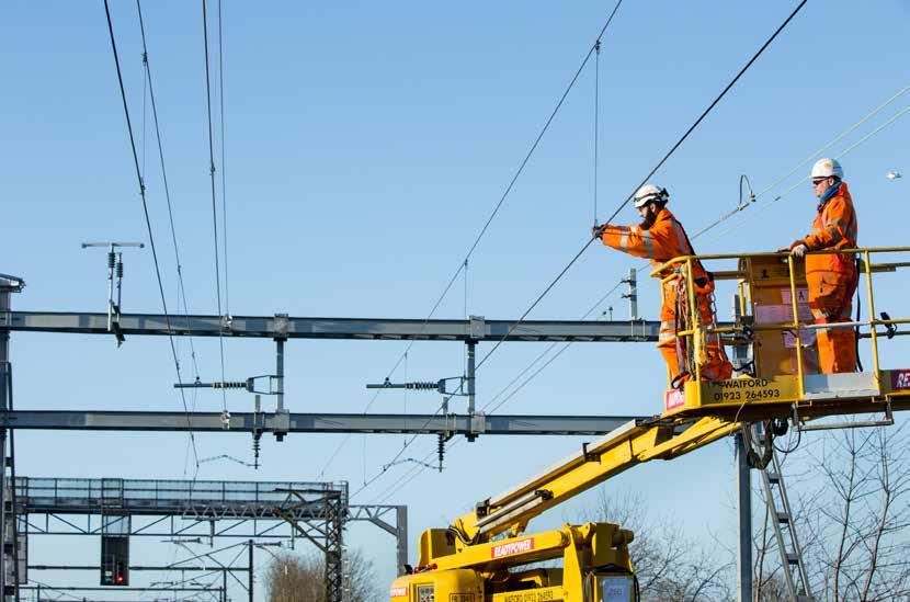
It was identified that Test Before Touch for OLE was not being carried out consistently and that life changing injuries would have been avoided if Test Before Touch had been
carried out. The new standard was issued on the 3 September 2022 with a compliance date of 4 January 2023, and it formalises and improves on the existing guidance on the Test Before Touch Lifesaving Rule for OLE.
Consultation
Development of the new standard was undertaken after much consultation with the regions of Network Rail and learning from other railway infrastructure managers. Network Rail also talked to other industries which have similar electrical infrastructure, dangers, and risk of injury. An important aspect of any new safety process is that it must be practical and not too onerous to apply, otherwise there is a risk that it will not be implemented correctly. This was a key objective when developing the new standard. The authority to work on OLE is contained with the Overhead Line Permit to Work, known as a Form C and also referred to as the Overhead Line Permit (OLP). Undertaking a Test Before Touch action, or
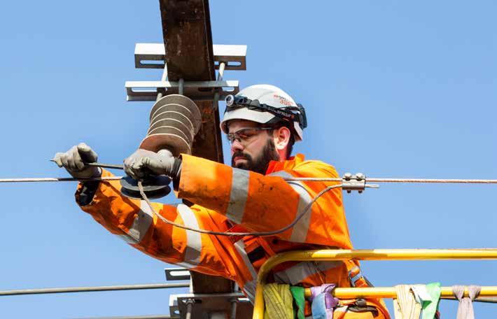
set of actions, using Live Line Indicators (LLIs) is the important final step in the OHL isolation process. It demonstrates to the Controller Of Site SafetyCOSS(OLP) - and members of the working party that the OLE is de-energised at the location of the test, and this helps to confirm that the working party members are within the safe working limits of the OLP.
The standard provides information to enable Test Before Touch actions to be identified, implemented, witnessed, and recorded in a consistent manner. NR/L3/ ELP/27720 only applies to OLE infrastructure, covering planned work, short notice work, and work following an emergency switch off.
A very important definition in the standard is that ‘touch’ or ‘touching a conductor’ is a task where it is planned for a person, tool, or item of equipment/plant to come within 600mm (2 feet) of an exposed conductor. If there is any uncertainty whether a task or task delivery method
Rail Engineer | Issue 199 | Nov-Dec 2022 18 ELECTRIFICATION & POWER
will result in an exposed conductor being touched, or coming within 600mm (2 feet), it must be assumed that this will happen and the standard followed.
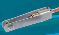


A Test Before Touch action, or set of actions, will be implemented whenever an OLP is briefed and issued to a COSS (OLP) by a Nominated Person. A Nominated Person is someone who has been trained and certified competent to use LLIs and fully understand the dangers of working on and around the overhead line system. To ensure there is flexibility in order to facilitate all types of work on OLE, one
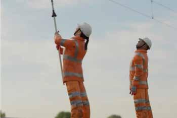
of four methods of Test Before Touch will be selected by those responsible for planning the implementation of isolation(s) and associated OLP(s), and in each case the standard says how the method will be recorded and briefed.


Method 1: Dynamic decision making for Test Before Touch actions.
This method requires an Equipment Competent Person (ECP) to be part of the working party. The ECP determines and directs the Test Before Touch actions. This method is most likely to be selected for tasks and delivery methods

such as high-level intrusive OLE maintenance, height and stagger adjustments, and OLE refurbishment / renewal.
Method 2: Pre-planned and pre-documented Test Before Touch actions.
This requires the Test Before Touch actions to be preplanned, documented and subsequently endorsed by a person holding Nominated Person competence. It is most likely to be selected where there is no ECP in the working party, for tasks such as bridge examinations and station canopy repairs.
Method 3: A pre-planned and pre-documented reduced set of Test Before Touch actions.
This uses a risk-based approach to identifying a reduced set of Test Before Touch actions which are preplanned, documented, and endorsed by two persons holding Nominated Person
Arthur Flury forked collar sockets and conical couplers
Holding the OLE securely for more than 50 years around the world, forked collar sockets and conical couplers from Arthur Flury are embedded in all of the UK’s electrified routes.

The cone holds the conductor tight and engineering tests have consistently verified that the conductor will break before slipping from the cone.
Manufactured in our ISO9001 appoved factory, Arthur Flury forked collar sockets and conical couplers hold full product acceptance with Network Rail and are included in OLEMI, Series 2 and Series 1 catenary designs.
Please contact our Milton Keynes office for further information. aflury.co.uk info@aflury.co.uk

Rail Engineer | Issue 199 | Nov-Dec 2022 19 ELECTRIFICATION & POWER
Arthur Flury (UK) LTD
competence. This is most likely to be selected where the requirements of the other methods cannot be complied with, or are too demanding when considering the task and task delivery methods and the nature of the electrification network covered by the OLP. This could be, for example, a station with multiple platforms and lines and significant numbers of discrete in-line OLE features.
Method 4: A Test Before Touch action prior to every occasion where it is planned to touch a conductor.
This requires a Test Before Touch action to be carried out prior to every occasion where it is planned to touch a conductor. There is no requirement to pre-plan or pre-document the location of the Test Before Touch actions. This method is most likely to be selected in a post Emergency Switch Off scenario or other urgent situation where there is no ECP in the working party. It might also be used where the planned arrangements for methods 1-3 cannot be sustained.
The implementation of the new Test Before Touch standard has been supported
by an impressive set of briefings, presentations, posters, videos, and social media posts; including a video to remind anyone how to use the standard if they have not had the need to use the process for some time.
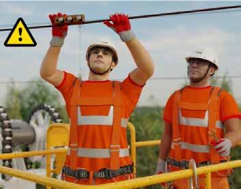
Martin O’Conner, Network Rail technical head for contact systems said: “It is really important for everyone to remember that the Overhead Line Permit (OLP) is the point of reference for electrical safety for the COSS (OLP) and members of the working party. The Test before Touch actions process and form is an additional measure and control against inadvertent contact with energised live OLE, and no matter which Test Before Touch method is selected the COSS
(OLP), or any other member of their working party, can request a Test Before Touch action.
“If there is ever any doubt when it comes to electrical safety, please ‘Choose to Challenge’ and raise your concerns. It may save your life or that of your colleague.”
Changes to the Earthing Strategy for OHL are also planned by Network Rail, including the concept of Optimised Earthing based on local worksite earths. These changes are dependent on trials which are being undertaken on the Wales and Western Region to inform the next steps.
Rail Engineer looks forward to reporting on these further measures once implemented, to further improve electrical safety when working on OLE.
Rail Engineer | Issue 199 | Nov-Dec 2022 20 ELECTRIFICATION & POWER



gb@furrerfrey.co.uk @furrerfreyGB www.furrerfrey.ch High Power Charge Stations Proud Winner for ‘TECHNICAL INNOVATION OF THE YEAR’ at Global Light Rail Awards 2020 Furrer+Frey are delivering the charging infrastructure for Coventry Very Light Rail Project. Vehicle design by Transport Design International k www.rail-media.com Subscribe to our free publications at www.railsubs.com Rail Engineer | Issue 199 | Nov-Dec 2022 21 ELECTRIFICATION & POWER
TDNS


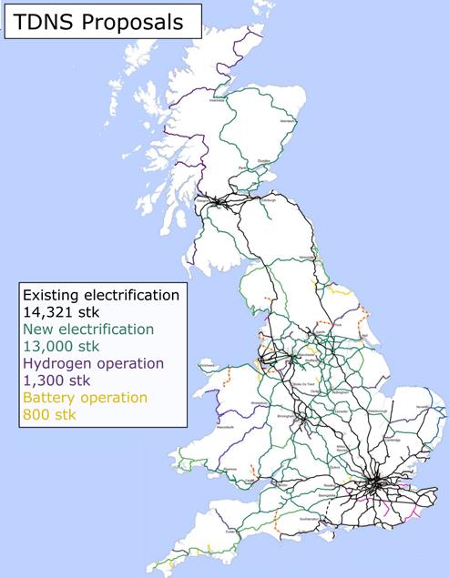
Two years ago, Network Rail published its Traction Decarbonisation Network Strategy (TDNS) which proposed a rolling electrification programme of 13,000 single track kilometres (stk). Although the Department for Transport (DfT) has not responded to TDNS, it used it to inform its Transport Decarbonisation Plan which states that “we will deliver an ambitious, sustainable, and cost-effective programme of electrification guided by Network Rail’s TDNS.”
Yet is difficult to reconcile this plan’s statement with comments made at recent conferences by Rich Fisher of the Great British Railways Transition Team (GBRTT) and Network Rail’s Andrew Haines, both of whom stated that the UK Government’s 2021 Comprehensive Spending Review considered TDNS to be unaffordable.

Thus, it seems that the UK Government has decided against a large-scale electrification programme. As a result, with only 46% of its tracks electrified, Britain will remain at the bottom end of the European electrification league table. In contrast, Scotland is committed to a rolling programme of electrification to decarbonise its railway by 2035. Transport Scotland’s view is it cannot afford not to electrify Scotland’s railway.
In this feature we consider why, in contrast to Europe and Scotland, the Westminster Government is reluctant to commit to electrification and whether rolling stock solutions are an effective decarbonisation option. To do so it is first necessary to consider some history.

The UK is 21st out of 32 in the European electrification league.
 (Right) The world’s first electric train.
Rail Engineer | Issue 199 | Nov-Dec 2022 22 ELECTRIFICATION & POWER
DAVID SHIRRES
Early electrification
In 1879 Werner von Siemens demonstrated the world’s first electric train in Berlin. This was a 150V DC locomotive hauling three small coaches. Its success inspired early electric railways which included the Volk’s Electric Railway in Brighton which opened in 1883 and is the world’s oldest operating electric railway.
Many railways were electrified in the first 20 years of the 20th century. With their power limited only by the capability of the supply, electric trains offered the high acceleration needed for suburban services and high power for heavy freight trains. Being inherently simpler and more efficient, electric trains also have lower maintenance and running costs.
During the interwar period, the Southern Railway adopted the 660V DC third rail system to electrify its suburban routes and lines to the South Coast. Largely as a result, Britain now has 4,536 stk of 650 DC third rail which now is 32% of the country’s electrified rail lines.
In 1932, a government committee decided that 1,500V DC overhead should be the UK standard, though few schemes were electrified in this way. These included Shenfield to Liverpool Street and the now closed Sheffield to Manchester line through Woodhead tunnel.
After the war
25kV AC electrification was introduced in Germany and France in the early 1950s. Its high voltage transmits a correspondingly higher power with lower transmission losses making it ideal for long distance railways that carry heavy traffic.
In 1956, British Railways (BR) adopted 25kV AC electrification except for third rail extensions. This was a brave decision given the constrained UK loading gauge and the lack of power semiconductors at the time which required the use of mercury arc rectifiers.
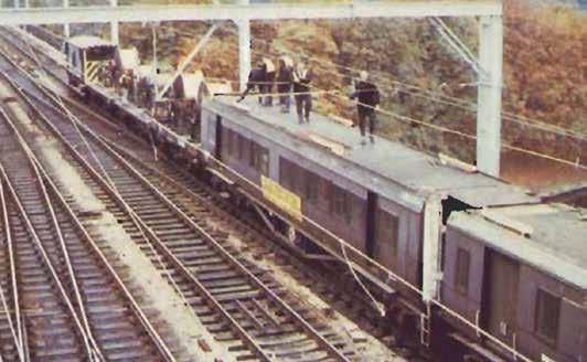
In 1960, Crewe to Manchester and the Glasgow suburban lines were electrified at this new standard. This was followed by lines from London to the West Midlands, Manchester, and Liverpool which were completed by 1967. This
new electrified inter-city service was a spectacular success as passenger traffic increased by over 80%. This sparks effect was evident on subsequent BR electrification schemes.
This West Coast Main Line electrification was extended to Glasgow in 1974. A BR booklet commemorating its opening advised how electric traction was important “in these days of increased awareness of need to conserve world energy resources, notably oil”. At that time there was no mention of rail decarbonisation.
The 1970s energy crisis led to a system-wide electrification proposal which was rejected as railways did not have political support. Some electrification schemes such as Ayr, Bedford, and Kings Lynn were progressed around this time. This ensured that skilled electrification teams were not disbanded and available for BR’s largest electrification scheme, the East Coast Main Line. This was done in two phases, from London to Hitchin (1976 to 1978) and from Hitchin to Leeds and Edinburgh (1984 to 1991).
At 1983 prices, this cost £344 million of which £206 million was the electrification and the remainder for new trains. The project was only 3.8% over budget and eight weeks late on a seven-year programme. The cost of its electrification work at today’s prices was £668 million for 2,200 stk, or £0.3 million per stk, which is a fraction of current electrification costs. This is not an entirely fair comparison as since then there has been a significant increase in traffic and improvements in safe working practice. Nevertheless, much could be learnt from the way that the ECML electrification was delivered.
Electrification post privatisation
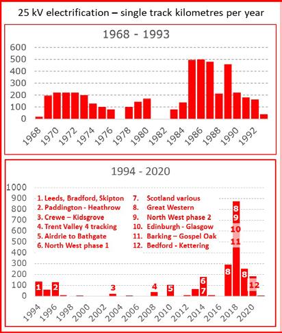
Though an average of 220 stk of electrification per year was delivered in BR’s final 15 years, the first 15 years of the privatised railway saw an average of 15 stk per year.
In 2007, the Government published its White Paper “Delivering a sustainable railway” which mentioned the need to reduce the railway’s carbon footprint. However, it considered that the
Rail Engineer | Issue 199 | Nov-Dec 2022 23 ELECTRIFICATION & POWER
Wiring from the top of a moving train would not be acceptable today.
case for electrification was not yet made, partly due to the possible development of low-carbon self-powered trains.
Three months later, the Chairman of the Association of Train Operating Companies (ATOC), Adrian Shooter, and Chief Executive of Network Rail, Iain Coucher, signed a joint letter stating that they believed the Government’s approach to electrification was wrong. Their succinct three-page letter explained why it was inconceivable to contemplate a 30-year strategy for rail which does not foresee much more electrification.
This and other lobbying had the desired effect as, in 2009, a £1.1 billion programme of rail electrification was announced. The Great
Western Electrification Programme (GWEP) from London to Oxford, Bristol, and Swansea was to be completed in 2016. Electrification of the Liverpool to Manchester line was also to be completed by 2013.
2010 saw the first significant electrification project for 14 years. This was part of the reopening of the Airdrie to Bathgate line which was completed to time and budget. As the line was electrified as it was built, its electrification was at a significantly reduced cost with no disruption.

Cost overruns
Unfortunately, GWEP and other electrification schemes were significantly delayed and over budget. By 2016, GWEP was expected to be up to three years late with costs increased from £1.6 billion in 2014 to £2.8 billion, or £3.4 million per stk.
In 2017, GWEP was curtailed by omitting Swansea, Oxford, and Bristol. The planned Midland Main Line electrification was also cancelled. The statement advising these electrification cutbacks advised that because bimode trains could seamlessly transfer from diesel to electric power, there is no longer a requirement to electrify every line.
Also, that year, Government announced that the new East West Rail link would not be electrified despite the low cost of electrifying a railway as it was built. Instead, the use of alternative green energy traction was to be explored.
Thus, Government support for a long-term electrification programme was lost as cost overruns forced it to conclude that electrification is the wrong technology.
One of the reasons for the high cost of electrification is evident from the graph showing the electrification mileage delivered each year. After many years with hardly any electrification, the industry had to ramp up to deliver 800 stk of electrification in 2018. This was inevitably
costly
Rail Engineer | Issue 199 | Nov-Dec 2022 24 ELECTRIFICATION & POWER
Airdrie to Bathgate line being electrified as it was built.
and inefficient with mistakes made due to skills shortages. In 2012, Rail Engineer reported that the plan was to have no less than 11 simultaneous electrification projects by 2016. In the event, at the peak of the programme there were only five concurrent projects!
Nevertheless, much of the responsibility for these cost overruns is within the rail industry. For example, unduly onerous design assumptions significantly reduced installation productivity. Piles were designed to be 12 to 15 metres long whereas long established empirical design guidance showed that they only needed to be 3 to 4.5 metres long. The 2019 Railway Industry’s Association’s Electrification Cost Challenge Report provides a thorough study of electrification costs during this period.
In Scotland, electrification of the Edinburgh to Glasgow main line (EGIP) was also in difficulty. Yet here the response was to ensure that the lessons were learnt rather than cancel electrification schemes. Scotland now has a rolling electrification programme with recent projects delivered to time and budget.

Decarbonisation reports
In February 2018, the then Rail Minister, Jo Johnson called on the rail industry to advise how it will decarbonise. His speech focused on innovation and made it clear that alternatives to electrification had to be considered.
The Rail Industry Decarbonisation Taskforce submitted its initial 68-page report in January 2019. This emphasised the need to maximise use of the existing electrified network using batteries to bridge gaps and called for further research and innovation into green traction technologies.
Its final 68-page report was completed in July 2019. This reached the rather obvious conclusion that rail decarbonisation required a judicious mix of cost-effective electrification, battery, and hydrogen trains. The report noted that 4,000 route kilometres of electrification may be required but only on page 34. This key conclusion was not mentioned in the executive summary.
In July 2020, Network Rail published its Traction Decarbonisation Network Strategy. This concluded that an additional 13,000 stk of electrification was required with hydrogen and battery trains operating on, respectively, 1,300 and 800 stk of the network. Its business case for various rates of electrification were appraised over a 90-year period as agreed with the DfT. One option to achieve net-zero carbon by 2050 required electrification of 355 stk per year. For this option, present value costs were between £6.3 and £9.7 billion and present value benefits were between £6.9 and £7.3 billion.
Scotland’s decarbonisation plan aims to deliver a net-zero traction railway by 2035.
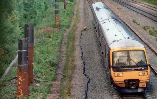
Overlong GWEP piles that could not be driven in.
Rail Engineer | Issue 199 | Nov-Dec 2022 25 ELECTRIFICATION & POWER
PHOTO: MODERN RAILWAYS
Hence, TDNS concluded that its net-zero by 2050 option had a net present value of between minus £2.8 billion and plus £1.0 billion. However, in accordance with DfT guidance, this does not include capital cost savings for cheaper electric trains. The capacity benefits of electric traction were also not considered.
In April 2021, the Railway Industry Association (RIA) published its ‘Why Rail Electrification Report’ which explained why electric traction is a future proof technology that will always be more efficient, powerful, and cheaper to operate than self-powered traction. This report was peer reviewed by members on the Institution of Mechanical Engineer’s Railway Division and sent to the Minister of Transport with a covering letter signed by 17 industry bodies.
Train costs
In March 2022, Britain’s passenger train fleet consisted of 15,277 vehicles worth roughly £25 billion. Yet there seems to be no strategic overview to get the best value from this asset.
The 2018 Long Term Passenger Rolling Stock Strategy (LTPRSS) shows that, since 2014, the DfT and individual train operating companies have ordered 7,187 vehicles at a cost of £13.8 billion - an average vehicle cost of £1.9 million. In 2014, the fleet size was 12,647 vehicles so these orders increased the fleet size by 2,650 vehicles. Although some of the new vehicles replaced life expired vehicles, the 2018 LTPRSS shows they left 3,940 serviceable vehicles surplus to requirements. Of these 889 were built since 1994 including 487 AC EMUs that could have operated under the wires of cancelled electrification projects, enabling diesel trains to be cascaded elsewhere to reduce the requirement to build new diesel trains. Thus, about a billion pounds has been wasted due to such large numbers of serviceable vehicles being surplus to requirements. Storing them would have required 19 kilometres of sidings with significant further expenditure to keep them in a serviceable condition. It is doubtful if the opportunity to use surplus serviceable EMUs was a factor in the decisions to cancel electrification projects.
Rail Engineer | Issue 199 | Nov-Dec 2022 26 ELECTRIFICATION & POWER
Cheaper electric trains
The 2014 LTPRSS considers that maintenance and leasing costs of electric trains are 37% less than those of diesel trains and that the annual electrification rolling stock savings from its high electrification scenario (equivalent to TDNS) would be £479 million.
In a recent presentation on ScotRail’s fleet strategy, the total operating costs per mile of electric and diesel vehicles were shown to be respectively £1.21 and £1.94 per mile. This is a 38% saving which is consistent with the LTPRSS figure.
Electric trains also have a higher maintenance availability. The LTPRSS also showed average availability for electric and diesel fleets to be respectively 91% and 88%. As a result, 3.8% fewer electric trains need to be purchased than diesel trains. Further fleet savings are possible with infill electrification that would allow electric fleets to be used more efficiently.
In recent times there has been a focus on rolling stock decarbonisation solutions to avoid the need for electrification including diesel bi-mode trains. These have duplicated traction systems which are more expensive to buy, maintain and operate. They also have less power when in diesel mode than conventional diesel trains and have higher track access charges as they are heavier than single power source trains.
Battery bi-modes also have a significant cost and weight penalty. An 8-car battery bi-mode on a half-electrified 250-kilometre route may require batteries weighing 9 tonnes costing £2.7 million as they are replaced every 5 to 10 years. These indicative figures are derived from having a battery of 60% of the 3,000kWh needed for Class 800/3 between London and Cardiff and rail traction batteries costing £1,500 per kWh and weighing 15kg per kWh. ScotRail consider’s that the per mile cost of a battery EMU is 18% more than a conventional EMU.
Why electrify?
Electric trains offer a future-proof technology as self-powered traction must carry its own fuel and convert it into electrical power with unavoidable efficiency losses. Furthermore, the power of electric trains is limited only by current that can be drawn from the overhead wire. For these reasons, the promotion of alternative selfpowered traction to avoid electrification work is generally misguided.
This also explains why railways throughout the world consider electrification to be a worthwhile investment as it offers a more cost effective, higher performing railway. Hence, the 2009 Coucher / Shooter letter told Government that it was wrong not to be considering a long-term electrification programme.
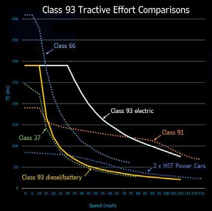
Tractive effort curves show throughout most of its speed range the new Class 93 tri mode locomotive has in electric mode, more than twice the power of its diesel/ battery mode.
Bi-mode Class 800 at Culloden under diesel power.
 PHOTO: LNERGRAEME ELGAR
Rail Engineer | Issue 199 | Nov-Dec 2022 27 ELECTRIFICATION & POWER
This letter also advised that Network Rail was developing an Electrification Route Utilisation Strategy (RUS) with a thorough technical, economic, and environmental assessment of the pros and cons of a wider electrification programme. This estimated the Benefit Cost Ratios (BCR) for its proposed electrification schemes which included a BCR of 3.1 for Basingstoke to Exeter and a BCR of 5.1 for Cross Country (Doncaster to Plymouth, Birmingham to Basingstoke).
Electrification also offers particular benefits for railfreight as electric locomotives are typically twice as powerful as diesel locomotives. Hence, it offers heavier and faster trains with increased network capacity by reducing the performance differential between freight and passenger trains. Currently, electricity provides only 4% of the energy for UK rail freight compared with 56% in continental Europe. Studies have shown that an electrification programme of around 700 stk (5% that proposed by TDNS) would enable about 70% of rail freight to be electrically hauled.
Decarbonisation is a relatively recent priority and should not be seen as the prime reason for electrification. Most of the world’s electric railways were authorised before carbon savings became an issue. Nevertheless, greenhouse gas (GHG) savings which are valued at £241 per tonne in the Treasury Green Book increase the profitability of electrification. Current railway diesel GHG emissions are 1.3 million tonnes CO2e per year, thus eliminating these is worth £313 million per year. Therefore, over 25 years, the average GHG saving per kilometre of the 13,000 stk TDNS electrification programme is £0.5 million per stk.
GBRTT’s plan
Having been told that the TDNS electrification plan is unaffordable, GBRTT is developing a decarbonisation plan which is a mix of targeted electrification and extensive use of diesel and, eventually, battery bi-mode traction. It recognises that this will not achieve the target of net-zero traction by 2050.
Phase 1a of this plan is delivery of 900 stk of currently committed electrification schemes and the procurement of diesel bi-mode trains to increase their vehicle mileage to 20% of the passenger fleet. This is estimated to save 55% of traction carbon emissions with minimal rail freight emission savings.
Bi-mode traction offers a relatively quick carbon reduction as it eliminates diesel traction under the wires. It also offers operational flexibility as routes are electrified and so is a useful decarbonisation transitional technology. However, it has higher capital and operational costs as well as poorer performance than electric traction.
In the final phase of the plan, possibly completed by 2070, there would be minimal use of diesel traction. This envisages 6,900 stk of electrification including freight infill lines and battery bi-modes accounting for 11% of passenger vehicle mileage. By this time, emissions will have been reduced by 80% with a 35% drop in freight emissions.
The Williams - Shapps report states that Great British Railways is being set up to take “strategic decisions that take a view across the whole system”. Yet GBRTT has not been allowed to do this for long-term traction policy which would help ensure a safe, cost-effective railway with the lowest possible emissions and sufficient capacity, reliability, and performance. Instead, by ruling out a rolling electrification programme, the UK Government has, in effect, decided what constitutes cost effective railway without any apparent analysis comparable to TDNS or Network Rail’s 2009 electrification RUS. This decision is likely to result in many poorer performing trains with significantly higher operational costs.
The history of UK rail electrification has had various ups and downs. One particularly noteworthy aspect was how, in 2007, the industry was able to convince Government to change its strategy after a letter from ATOC and Network Rail telling Government that its approach to electrification was wrong.
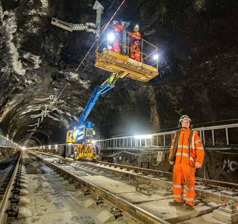
This Coucher / Shooter letter stressed that electrification “is an area that, perhaps above all others in rail strategy, is deserving of a serious and dispassionate analysis of the commercial, economical, and environmental benefits of the options.”
Fifteen years later, these words are particularly appropriate.
Rail Engineer | Issue 199 | Nov-Dec 2022 28 ELECTRIFICATION & POWER
Safety during a time of change
Since 2003, the Rail Safety and Standards Board has become one of the world’s go-to sources of technical knowledge for rail safety.
And as the industry evolves, we’re well placed to help organisations manage change and limit the unintended consequences that can affect safety.
That’s why we’re putting resources into cutting-edge data and systems analysis, to uncover new risk indicators that may offer early intelligence of possible safety concerns. Helping our members identify areas to investigate and monitor before they become a problem.

To find out how your organisation could benefit, visit rssb.co.uk/railtransformation

Risk indicators
maintenance & planning Air quality Performance optimisation
value Risk profiling Data insights
intelligence
Rail transformation
Asset
Social
Safety
Emerging technologies We’re with you every step of the way
Static Frequency Converters IMPROVING THE 25KV
CLIVE KESSELL


Getting a reliable 25kV power supply is important in the thrust to obtain more railway electrification commitment from the government. All too often, reports emerge of train services being disrupted because of problems with the power supply.
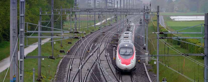
Over the years, the design of overhead catenary supports and conductors has been standardised and enhanced. Also, by having the 50kV auto transformer option, this gives the capability of delivering more power whilst negating the need to have booster transformers and return conductors. One might comment that the structures and gantries have become excessively sturdy judging by the GW main line project but, overall, the emphasis has been to reduce the cost of electrification.
But what about the power from the electricity supplier? Is this robust and reliable - and what happens if power to a substation fails? A talk given recently by Tobias Thurnherrs from Hitachi Energy, at an event organised by the IET Midlands Power Group, looked at one way of improving the quality and resilience of power feeding the railway.
Conventional power feeding
The electricity supplier has a multitude and mixture of different power lines ranging from 275kV and 132kV high voltage pylon lines down to 33kV and 11kV for local distribution. These operate in three-phase, which is an efficient and balanced way of distribution. For the conventional feed, only the higher 275kV or 132kV are used to supply the catenary, this being achieved from where these power lines run close to the railway.
A transformer connects only one phase of the grid to the 25kV overhead line at what is known as a substation (sometimes called a feeder station). Ideally, these substations are around 25 miles apart. This is not an ideal arrangement as it creates an imbalance between the three phases. However, for transmission lines of 132kV and above, this is not generally an issue as the load on each phase is much greater than the power
taken by a railway substation feeding the 25kV OLE.
Midway between substations is a track sectioning cabin (TSC) which separates the feed sections from the adjacent substations. Since the two power sources may not be in phase or indeed will have slightly different voltages, the TSCs control what is known as a neutral section. This is a short length of catenary that is unpowered and prevents the two feeds from combining and causing disruption to the grid supply. Normally, trains coast through these neutral sections at speed but it is not unknown for a train with only a single pantograph to become stranded in the neutral section if it is moving very slowly or has stopped because of an unrelated problem. The train thus loses all power, and a recovery train or locomotive has to be sent out to pull or push the stranded train a short way to regain a power supply.
Should a substation fail, then it is disconnected from the 25kv catenaries and the TSC connects both sides of the neutral section to allow power to be extended a further 25 miles to the next TSC point. In such circumstances, the
Rail Engineer | Issue 199 | Nov-Dec 2022 30 ELECTRIFICATION & POWER
voltage drop on the catenary can be significant (it may get as low as 17kV) thus impacting on the power needs of trains.
None of this is liked by the grid authorities. The transformer being a passive component represents an inductive impedance and creates both active and reactive power related to the railway load. The feeding grid sees an undesirable power factor and an unbalanced load.
Static Frequency Convertors


To overcome some of these difficulties, a lot of research and effort has been put in to designing an intermediate device between the transformer and the catenary feed. This is known as a Static Frequency Convertor (SFC). It is something of a misnomer as whilst it can convert the 50Hz frequency into something different, its main role is to control the precise voltage, phase angle, and frequency of the output.
If this can be achieved, then the power output from adjacent substations can be made identical and thus the neutral section can be dispensed with if the sections either side are fed from SFCs . In the process, the control of the active power flow is better controlled and the reactive power reduced. That, in short, is what an SFC attempts to achieve.

SFCs work by taking a threephase balanced load from a high-voltage transmission line, converting it to DC and then to


a single phase 25kV OLE supply. As a result, their use does not affect the balance between the transmission line’s three phases. Hence, they can be fed from a local distribution network’s 33kV supply.
The benefits of feeding the 25kV OLE from a 33 kV supply are considerable as this significantly reduces the cost of substation connections and offers greater flexibility in the location of substations.
Other benefits are that, in the longer term, SFCs could replace existing substations so that a single section of the line need not be dependent on only a single feed. With multiple feeds from different substations, more power can be delivered to trains and thus fewer substations are required. At peak demand, a train will take power from more than one substation and thus the capacity to provide the necessary power is enhanced. The catenary voltage will be better stabilised as it is no longer vulnerable to a single threephase supply from the grid being below specification. Further, the capture of regenerative braking is enhanced. Should a short circuit occur on the catenary system, the control of the short circuit current can become more manageable.
It is unlikely that these other benefits will immediately impact on existing electrified lines as this would require the replacement of existing substations, perhaps during renewals or power supply upgrades. For new electrification schemes, SFCs should represent a considerable cost saving.
The trial site
A number of countries are already using SFCs but for Britain, a trial site was needed. By chance, a new supply was needed for the Doncaster depot, where one of the Hitachi Azuma trains are stabled for maintenance and cleaning. This is known as Potteric Carr, just south of the station, and the opportunity was taken to use this as a substation to power the 25kV wires from Doncaster to Bawtry, some eight miles to the south. Should there be a fault in adjacent feeder stations, the power can be extended to Retford in the south and to York in the north.
Conventional transformer substation feeding concept.
Rail Engineer | Issue 199 | Nov-Dec 2022 31 ELECTRIFICATION & POWER
Rail Static Frequency Converter (SFC) feeding concept.
A contract was let with Hitachi Energy to supply the SFC as part of a turnkey package that included site preparation, groundworks, foundations, transformers, harmonic filters, heat exchangers, a cable connection to the OLE, and commissioning. The substation would be integrated to the national SCADA system to enable control from the Electrical Control Room (ECR). The local 33kV from the national grid had to be upgraded and equipped with gas insulated three-phase switch gear. The SFC is designed to integrate with other SFCs north and south when those substations are converted.
From the Network Rail position, the SFC rating is required to deliver peak power of 46.5MW for two seconds, continuous power of 30.5MW, a unity power factor over the voltage range of 25kV to 27.5kV. It has to withstand a temperature range of -25ºC to +40ºC during normal operation, be capable of operating with any harmonics generated by the traction units, and must not interfere with track circuits or other elements of the signalling. In addition, the SFC must comply with IEC / EC and UK power standards, mainly BS EN 50121-1,2,5 plus Network Rail Group Standards NR/SP/ SIG/50004 and RT/E/C 50008. The SFC uses integrated gate commutator thyristor (IGCT) technology with high-quality semi-conductors to guarantee a long life and low losses.
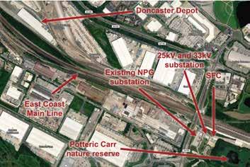
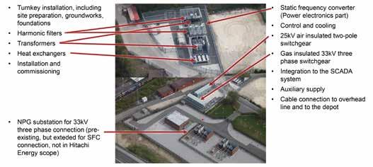
Also, the SFC has to operate with adjacent substations still using the traditional transformer fed section and to other SFCs that might be supplied by a different manufacturer. This will ensure degrees of freedom to share power and including synchronous coupling with transformer fed sections. It also means that a data transmission link will need to connect and control the synchronisation, but this will be part of the SCADA system.
Installation and testing
The SFC is installed within a containerised building where the incoming grid supply is connected with a threelevel neutral point clamped converter and a 100Hz filter to filter out any pulsating load from the single phase of the grid. The SFC contains a phase measurement unit (PMU) that measures the amplitude and phase angle of the output voltage, which is given a time stamp that can be transmitted to adjacent substations and the ECR. This enables effective load sharing and allows to offset the angle
measurement to prevent unwanted power flow through the catenary.
Short circuit faults do happen occasionally which can reflect back into the grid and cause a voltage dip. When using an SFC, this limits the effect a short circuit can have compared to a transformer fed arrangement. Protection relays are provided to monitor impedance and so detect and isolate a fault. Sufficient current must be provided to the SFC during a fault condition. This has been tested at Potteric Carr and a stable output current is provided during the fault. A smooth ramp up of voltage occurs once the fault is cleared.
SFCs do generate noise and at Potteric Carr, a house and a nature reserve are close by. The walls of the building are equipped for fire protection that provides the necessary insulation that ensures noise emission levels are within the required limits.
Testing of the SFC has been extensive, especially the software testing which used a digital real time simulator, followed by on site testing, mostly done at night to prove suitability for both old and new type trains.
In conclusion, whilst SFCs themselves are more costly than the transformer fed system they offer significant reduction in supply connection costs. They also offer the benefits in terms of a simpler, more resilient, and evenly balanced power supply with the prospect of needing fewer substations in the future, making this a worthwhile investment. Time will tell if the necessary investment will be forthcoming.
Rail Engineer | Issue 199 | Nov-Dec 2022 32 ELECTRIFICATION & POWER
Safety Summit
Book
Call 01530 816 456 visit railsummits.com email events@rail-media.com
Rail Safety Summit 2023

14th March Holywell Park Conference Centre Loughborough University
We’re used to hearing phrases like ‘Safety First’. They’re a reminder that safety is never off the agenda.
Britain’s railways have maintained an enviable safety record in recent years, but reports of incidents and near misses demonstrate that there is room for improvement.
Register for the Rail Safety Summit to hear HSEQ leaders from RAIB and Network Rail discuss the issues that matter.
Speakers confirmed for 2023 so far:
• Andrew Hall, Chief Inspector, Rail Accident Investigation Branch (RAIB)
• Ian Prosser, HM Chief Inspector of Railways and Director of Railway Safety, Office of Rail Regulation
• John Jebson, OHSE Director, McGinley Support Services (Infrastructure)
• Marian Kelly, Head of SHE, London Underground
• Nick Millington, Acting Route Director, Wales and Borders Route, Network Rail
• Peter Dearman, Independent Consultant (Former Engineering Director, Atkins), Dearman Engineering
• Prof Sarah Sharples, Professor of Human Factors, Nottingham University
• James Le Grice, Head of Rail Safety and Standards, Department for Transport (DfT)
• Ali Chegini, Director of System Safety and Health, RSSB
• Rupert Lown, Chief Health & Safety Officer, Network Rail

• Leo Scott Smith, CEO, Tended

your delegate place or contact us for sponsorship opportunities at this essential rail event
- Sponsored by -
30 YEARS OF QTS
Having just celebrated its 30th birthday, QTS is now well known for its rail infrastructure work. Not so well known is the origin of the initials that make up its company name which show the company’s origins. To find out more, Rail Engineer was glad of the opportunity to meet the company’s founder Alan McLeish and Engineering and plant compliance manager, Adrian Phillips at QTS’s base in Drumclog, South Lanarkshire
Alan was 32 years old when he founded the company. As a teenager he had a job as a seasonal gardener and soon started working in forestry when he qualified as a tree surgeon. Doing this work, he developed his love and understanding of the natural world. Based in Ayrshire, he did a lot of tree surgery work for local Councils in the early 1990s. It was then he became aware of the business opportunity of rail vegetation clearance.
Quality Tree Surgeons

With a small loan from his mum, Alan took the plunge and founded Quality Tree Surgeons in 1992 to do rail vegetation work. Initially, he hired the required plant and in 1997 bought a Road-Rail Unimog. In 2000, QTS acquired Rench Farm at Drumclog, a remote site in the moors 20 miles south of Glasgow. It then had more than 40 employees and became a limited company. This move provided a much-needed base, helped the company expand its rail infrastructure work, and gave everyone a strong direction.

Alan explained that, when QTS moved to Rench Farm, it had separate divisions for construction, civil engineering, and rail. Of these, the rail business had strong growth whilst the other divisions were not so profitable. In 2011, he took the decision to wind up the construction and civil engineering divisions. Staff were then given the option to transfer to the QTS rail business. As a rail-only business, the company then went from
strength to strength. This was helped by QTS getting its Principal Contractor’s licence from Network Rail around this time.
With the acquisition of Rail Electrification Ltd in June 2021, QTS added electrification to its portfolio.
Over its 30 years, QTS has grown from its original roots in tree surgery to a company undertaking all forms of rail infrastructure work that has seven offices nationwide, almost 600 employees, and a turnover of more than £100 million.
Of this, vegetation work accounts for less than 20% and civil engineering is more than 50%. The remaining work consists of fencing, drainage, plant hire, electrification, isolations, and training.
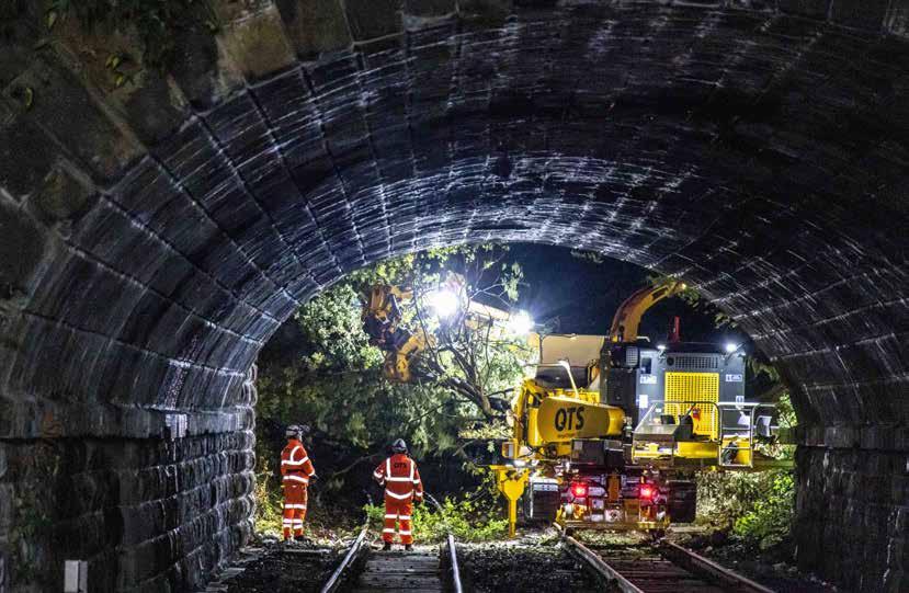 DAVID SHIRRES
FEATURE 34 Rail Engineer | Issue 199 | Nov-Dec 2022
Rench Farm in 2000.
Alan believes that the key reason for QTS’s success is the importance it places on investing in people to attract, retain, and reward talent. He advises that the company’s board have all worked their way up internally within the business. This ‘hands on’ experience also gives the company the agility that he considers to be essential. This enables QTS to invests millions of pounds each year on plant innovation which is one of Alan’s personal passions.
Plant innovation
It was clear from our discussion that Alan and Adrian work very much as a team to develop innovative rail plant, particularly for
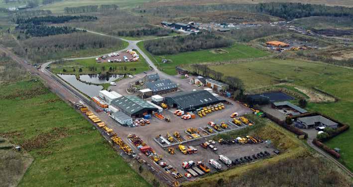
vegetation work. Alan has much experience of vegetation clearance equipment mounted on large forestry machines and the two work together to overcome the challenge of mounting such kit on on-track plant. Adrian explained that in planning these machines, there is a lot to consider, including ensuring that each machine fits within the railway loading gauge and can provide a stable platform when operating on the relatively narrow track gauge.
Over the last 30 years, QTS has developed various unique items of on-track plant for vegetation clearance work, including the original Mega Chipper. Also, part of the fleet are Forwarders, a Compactor, and a Baler. In forestry work,
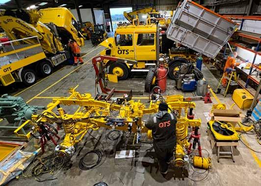
a Forwarder is a vehicle that carries felled logs clear of the ground to an unloading point or is used together with other machinery. The rail Forwarder that has been developed by QTS features the power of the Mega Chipper V2 mounted onto the back. This allows the Forwarder to chip 150m3 per hour.
QTS’s first Mega Chipper was developed in 2015 and has a 27-inch chipper powered by a 300hp engine. Feedback
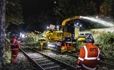 (Below) QTS Rench Farm facility in 2022.
(Left) Rench Farm’s workshop.
FEATURE 35 Rail Engineer | Issue 199 | Nov-Dec 2022
(Above) Mega Chipper V2 in action.
Tree about to be compressed in the Compactor.
from its operators was used to produce the Mega Chipper V2 which was introduced in 2021. This has a 460hp engine which has an output of 150 cubic metres per hour and so can chip a 40-foot tree in under 60 seconds. It also has a metal detector which stops the machine if, say, a Pandrol Clip is about to be fed into the chipper. For smaller vegetation clearance work, QTS has several Road Rail Unimogs which have been adapted to carry a frontmounted Ducker Chipper.
Forestry management
Where it is acceptable to do so, the Mega Chipper can spread chips to a 100mm depth. However, where chipping is not permissible, the vegetation Compactor comes into its own. This was introduced by QTS in 2020 and is secured to a standard trailer with ISO twist locks. It is the
only plant of its kind currently operating on the UK rail infrastructure. The Compactor works in conjunction with a Liebherr Road Rail Excavator with a tree shear attachment that can remove vegetation up to 400mm in diameter up to eight metres from track without need for manual felling with no impact on lineside ground or drainage.
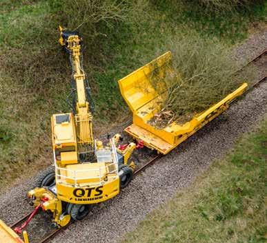
The Compactor has moveable sides which open to receive vegetation from the excavator and then close to compress it to an in-gauge load before more vegetation is received. In this way, it can hold 10 times the volume of a traditional trailer. Once the Compactor has moved the removed vegetation off site it can be processed with whole tree chippers and potentially used as biofuel. This process is a better option than noisy chainsaws as it significantly reduces the impact on lineside neighbours. Another well-proven forestry management technology that QTS has adapted to rail is its Baler. This has a powerful compactor and fast-rotating bundling system which can produce around 20 bundles per hour that are typically three metres long, 600mm in diameter, and weigh 400 kilogrammes.
These can be safely left on site to support wildlife, in particular mosses, lichens, and insects. Alan is certain that this is a world-first as he has been unable to find such a rail baler anywhere else. When this joins the QTS fleet in 2023 it will reduce the time and cost of vegetation clearance by
eliminating the need to dispose of cleared vegetation off site where chipping is not possible.
QTS has also developed a Weed Control Unit which holds 3,000 litres of water with a separate tank that injects chemicals into the spray nozzles. It can spray up to 6 metres up a cutting or down an embankment and has two hand lances for spot spraying. Except for such spot spraying, the machine can operate under live OLE.
For drainage work, the Rail Mega Vac has been developed. This has a 120-metre hose reel that can jet 300 litres of water per minute at 138 bar. Waste and debris that has been jetted into catch pits is then extracted with a vacuum that exhausts 3,000 cubic feet per minute to a large capacity waste system that can hold three cubic metres of waste and seven cubic metres of water. The Rail MegaVac is used in conjunction with a CCTV mini crawler system to survey each drainage pipe.
Long reach plant has also been developed. The Road Rail Mega Crane can lift 810kg at its maximum reach of 28 metres, whilst the Road Rail Gallmac Mobile Equipment Platform (MEWP) has a capacity of 350kg at an 11-metre reach. This makes it suitable for ash die back as such trees are not structurally safe for climbing.
Social value
QTS’s innovative plant fleet is the result of an investment of millions of pounds each year. Yet for Alan, investing
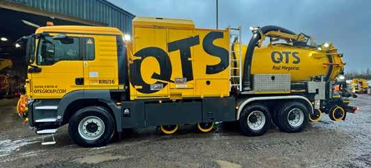
FEATURE 36 Rail Engineer | Issue 199 | Nov-Dec 2022
QTS’s Rail MegaVac.
in people is also crucial. This includes supporting the communities in which QTS operates by, for example, sponsoring young athletes and involvement with various local and national organisations including Women in Rail, Darvel Football Club, and Ayr Rugby Club. From 2018 until earlier this year, QTS was the principal sponsor of the Youth and Philanthropy Initiative in which teams of pupils work to understand the social issues affecting their local community.
In each school, there is a competition in which teams compete for to a £3,000 grant for their chosen local charity. Engaging with young learners is also a real focus for QTS. Earlier this year, the business hosted its inaugural ‘Future of Rail’ event at its Drumclog HQ, in partnership with AmcoGiffen, Carnell, and Scotland’s Railway. Over 150 Ayrshire and Lanarkshire pupils attended the first day of the event which was designed to encourage young people to consider careers in the rail industry. The youngsters saw some of the QTS plant in
action and had the opportunity to speak to other young people working for AmcoGiffen, QTS, and Network Rail about their routes into rail.
In 2022, QTS launched its Rail Skills Academy, in partnership with East Ayrshire Council and the Young Person’s Guarantee. The unique programme, delivered by QTS Training, is designed to help such youngsters acquire railway competencies. These included PTS and track induction as well as small tools and first aid.
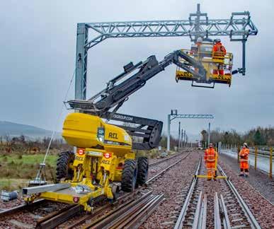
In August, 10 youngsters successfully completed this programme of five weeks of classroom training and four weeks of on-site work experience. Five then joined QTS and five joined other contractors. The second cohort of young people graduated in October and were again all helped into finding employment.

In recognition of such partnerships in both England and Scotland, the company’s work with businesses across the UK, QTS became the first dedicated UK rail company to receive a Social Value Quality Mark in April 2022.
Training
QTS Training was launched in 2009 and is a National Skills Academy for Rail (NSAR) gold-rated provider of railway safety critical and on-track plant training. It is also certified by various other industry bodies such as the prefabricated access supplier’s and manufacturers association (PASMA) and the Construction skills certification scheme (CSCS).
In February, a bespoke rope access training centre was completed at Rench Farm and then approved for use by the industrial rope access trade association (IRATA). This new facility complements the existing training facilities which include a 700-metre double line railway training track, an underground confined space chamber and tunnel system.
The first youngsters to successfully complete the QTS Rail Skills Academy programme.

(Below left) Rope access training centre.
(Below right) Rench Farm’s OLE training facility.
FEATURE 37 Rail Engineer | Issue 199 | Nov-Dec 2022
In addition to the training provided at Rench Farm, QTS also offers training in Nottinghamshire and its first standalone site in Knottingley. It offers over 150 courses, not all of which are railway specific. These cover on-track plant, railway safety roles, health and safety, rope access, confined spaces, construction, and personal development.
This year, QTS was also awarded the highest accolade by Investors in Young People as it secured the platinum award, one of only eight businesses in Scotland recognised at this level.
YouTube

A tour to see the offices, workshop, training facilities, rail infrastructure, and the various types of on track plant at the extensive Rench Farm facility showed how much QTS has achieved in its 30 years, which includes the 23 years since QTS established its base there.
The board room has a model of the recovery of the Class 66 locomotive which had to be cut up on site when it went down a hillside after it derailed at Loch Treig. Though this was 13 years ago, this recovery of this locomotive is still remembered as a particularly challenging job, as can be seen on the QTS You Tube channel (search Loco Recovery QTS).
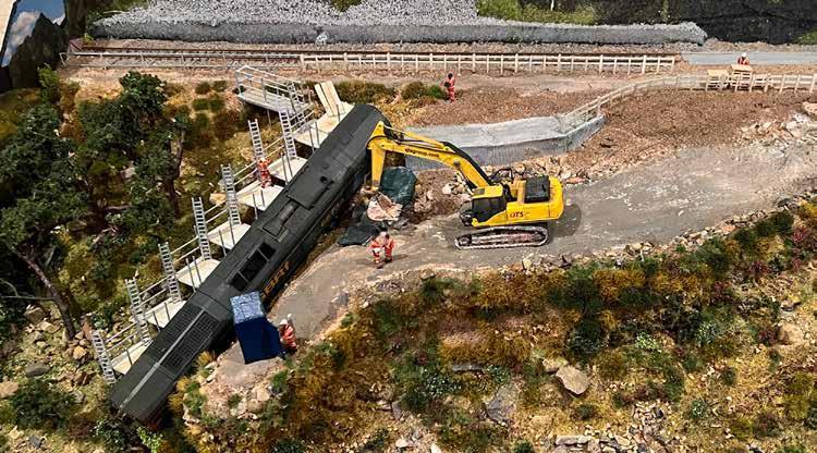
The QTS YouTube Channel also shows the on-track plant featured in this article in action. When an unsafe hotel building closed the Ayr to Stranraer line for many weeks in 2018, advantage of this closure
was taken for the Mega Chipper v1 to clear a six-metre-wide strip either side of the line along 25 miles of track in eight weeks. A more recent video shows the Mega Chipper v2 clearing vegetation along 32 miles of track for the Glasgow to Barrhead and Kilmarnock electrification project.
Electrification work is featured in other YouTube videos. One shows the electrification of 800 metres of sidings using portals spanning six tracks at Hitachi’s Newton Aycliffe plant. Another shows new OLE portal structures being installed at Morpeth in connection with the recent embankment stabilisation work.
Clearing drains with the Railboss RRBO1 on-track machine is the subject of another YouTube video. Another shows a novel technique that doesn’t involve on-track machines. This was the installation of tactile studs at Crainlarich station using a small multi-hole drilling trolley developed in Australia.
Alan also mentioned another novel job which was the recent use of a helicopter to help renew five kilometres of fencing in a remote area on the West Highland line above Loch Long to prevent livestock getting on the line. The helicopter delivered 20 tonnes of material in 21 lifts.
With the award of Network Rail Scotland’s £100 million Geotech framework contract in 2019, QTS will be undertaking further challenging jobs in remote areas which will make the best use of their specialised machinery and well-trained staff.
In its 30 years, QTS has come a long way since it was Quality Tree Surgeons. As Alan says, it has now morphed into Quality Technical Services. It seems clear that key to QTS’s success is its generous investment in plant innovation and people, and in particular the development of young talent. Alan McLeish is surely right in his firm belief that investment in people and innovation across the rail sector will continue to create more jobs and promote positive socioeconomic change throughout the UK.
Rail Engineer is delighted to announce that Alan McLeish was honoured with the Lifetime Achievement Award at the 2022 RailStaff Awards on Thursday 24 November. Alan faced strong competition, but his contribution to the industry over the past 30 years, as well as his dedication to the people who work for him, wowed the judging panel. Congratulations Alan!
Alan McLeish won the RailStaff Awards Lifetime Achievement Award.

FEATURE 38 Rail Engineer | Issue 199 | Nov-Dec 2022
Model of Class 66 locomotive recovery at Loch Treig and inset QR code for QTS YouTube channel.
MORE THAN AN AWARD


Thank you to all those that made the 2022 RailSta Awards so special! You can be part of this amazing event in 2023. Contact the Rail Media team to enquire about sponsorship opportunities on 01530 816 444. Photos & Videos now live on www.railsta awards.com


THE RAILSTAFF AWARDS 2023
THE NEC, BIRMINGHAM // NOVEMBER 2023
GCRE
offers testers a welcome in the hillsides

The global rolling-stock market is estimated to be worth £55 billion and growing at 4% per annum. Hence, there is a significant demand for rail test facilities - of which few have long loops that offer high-speed running, such as the Czech test facility at Velim. Moreover, most test tracks focus on rolling stock, rather than infrastructure testing.
After engaging with manufacturers wishing to build rolling stock factories in the UK, the Welsh Government became aware of the need for international-standard rail testing facilities. To develop this idea further, a mining site on a hill in South Wales was identified as an ideal site. This was the former Nant Helen opencast mining site and the Onllwyn washery at the head of the Dulais Valley, 15 miles northeast of Swansea. This has a large area that can be purchased at an affordable price at a location where testing can be done 24 hours a day. It is rail-connected and close to deep water ports.
The vision is that this testing centre will become a leading hub of research and innovation that will provide customerspecific engineering and operational test programmes as well as engineering measurement and certification services. It is also the intention to facilitate collaborative joint projects from manufacturing, research, and academic sectors. It will in fact become the Global Centre of Rail Excellence (GCRE).
GCRE

The site straddles both the local authority areas of Neath Port Talbot and Powys which are strong supporters.

GCRE is expected to provide high-quality jobs, promote wider inward investment, and provide the regional economy with GVA (gross value added) benefits of up to £70 million over 10 years. However, building such a large, comprehensive facility on a disused mining site at the top of a Welsh mountain is not cheap, with the cost now estimated to be £250 million.
To progress the project, a new company - GCRE Ltd.has been created to deliver the project for which financial commitments of £50 million and £20 million have been obtained from the Welsh and UK Governments respectively, with a further £7.4 million of R&D funding being provided through Innovate UK. Planning permission from both Councils was granted in summer 2021 and the 700-hectare site was
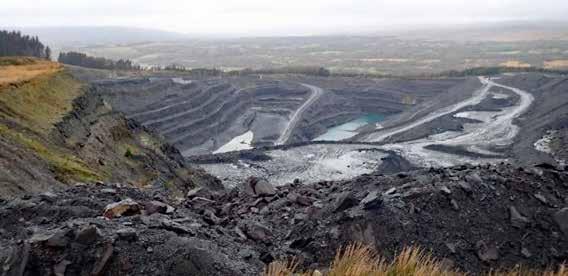 DAVID SHIRRES
40 Rail Engineer | Issue 199 | Nov-Dec 2022 PERMANENT WAY & LINESIDE ASSETS
Nant Helen open cast mine.
purchased from Celtic Energy in late September. In addition to the government grants, the intention is to fund this from equity investment of more than £100 million and debt finance of around £70 million.
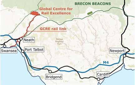
Simon Jones, GCRE’s chief executive, gave more information when he spoke at a recent event in Cardiff that sought innovative ideas for construction of the GCRE facility. He stressed that this was a unique UK project that will provide a site where technologies can be tested, demonstrated, and certified for safe use on the UK and international railways in a safe, offline, but realistic environment. He advised that GCRE would offer three core services: rolling stock testing; infrastructure testing; and storage and maintenance.
Simon also explained that there had been lots of commercial interest with potential users including Network Rail, Transport for Wales, passenger and freight train operators, TfL, HS2 as well as infrastructure suppliers of all sizes. GCRE’s chief commercial officer, Kelly Warburton, reinforced this point as she spoke of the strong interest she had received from many European companies when promoting GCRE at Innotrans.
Developing the site
The GCRE site has been subject to extensive surface and subsurface coal mining activities over the past century. Mining there ceased in 2021 and, as a result, it currently consists of brownfield restored land, overburden mounds, coal stocking areas, and mining facilities. The Nant Helen Open Cast mine is at the top of a hill whose summit is 335 metres above ordnance datum (AOD) and is at the head of three principal river catchments.
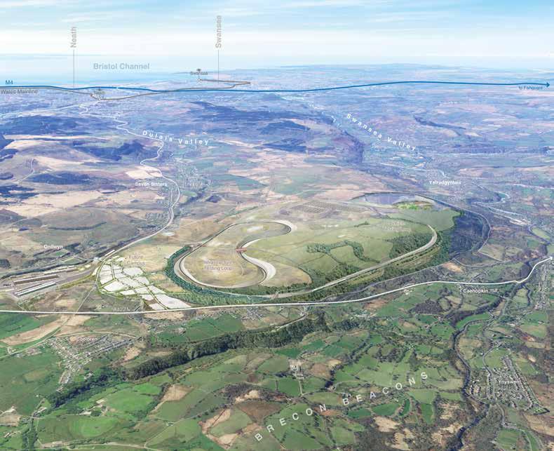
41 Rail Engineer | Issue 199 | Nov-Dec 2022 PERMANENT WAY & LINESIDE ASSETS
Test loop cross section –Loop will be built with a single track with passive provision for a second.
One of these is the Dulais valley, which has the rail line to the Onllwyn Washery Centre which is 230 metres AOD. Trains access this line by leaving the main line at Briton Ferry station and reversing at Swansea’s Burrows Sidings.
The site’s northern boundary is a kilometre from the Brecon Beacons National Park. About 116 hectares of the site is designated as common land and has several public rights of way across it. Although some of these will be extinguished, better connected routes will be created. It is anticipated that 12km of cycle paths will be created.
A detailed environmental statement produced by Arup was completed in 2020. This explains how the GCRE has been developed to mitigate environmental constraints which
included: visual impact from the adjacent national park; noise and traffic impact on adjacent settlements; topography and ground conditions; and ecological sensitivities as well as water resources and drainage. The site also has features of historic interest including the 1830s Ystradgynlais tramway which is a scheduled monument. Another constraint is the 130kV and 400kV overhead transmission lines over the site.
Although the Nant Helen hilltop has the large area needed for its test tracks, it is not flat. Hence, its tracks will require cuttings up to 25 metres deep and embankments up to 35 metres high which will require three million cubic metres of earth movements. These earthworks were designed to maintain an
acceptable cut and fill balance. The Nant Helen test track will be between 245 and 270 metres AOD. Rail access to the test tracks from the Onllwyn servicing area is up a rail line with a 1 in 37 gradient.
The environmental statement explains how, in September 2018, the design was developed by considering seven base loop options that varied in speeds between 80 and 125mph. The final design has a 6.9km vehicle testing loop and a 4km infrastructure testing loop. These loops will have 25kV overhead line electrification and a 3-metrewide access track. They will be single track with twin track OLE cantilevers and a 17.5-metrewide formation to give passive provision for double track.
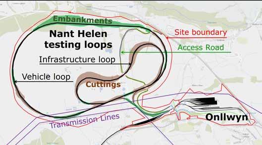
GCRE facilities
The Nant Helen part of the site will have the test loops with full 5G and GSM-R coverage. Their OLE will be fed from a static frequency converter powered by a 12MW onsite solar farm and a direct connection to a 20MW wind farm. The intention is for GCRE to become Britain’s first netzero carbon railway.
The 6.9km vehicle testing loop will be constructed to Network Rail’s Cat 1A 200 km/h TSI standard. Potentially, part of it could be built to HS2 standard. It will have 530 and 800 metre radius curves with two straights of 1,100 and 1,430 metres. Although built to 200 km/h standards, its configuration will only allow 177 km/h running. However, expert advice is being sought on whether 200 km/h might be possible. Signalling will be ETCS Level 2 with no conventional signals. However, the site could potentially also be used for Level 3 testing.
The 4km infrastructure testing loop will be constructed to typical Network Rail 120km/h standards to various track designs using recycled equipment where possible. The maximum speed on this
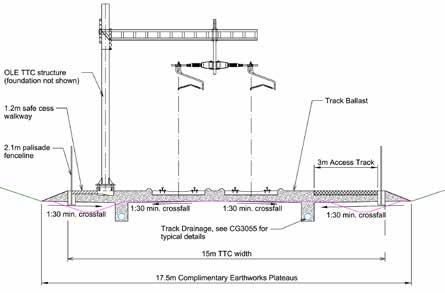
42 Rail Engineer | Issue 199 | Nov-Dec 2022 PERMANENT WAY & LINESIDE ASSETS
loop would be 65km/h. It will have 220, 260, and 425 metre curves of about the same length and an 803 metre straight. The OLE on the infrastructure loop will be UK Masterseries and the vehicle loop will be Series 1. There will be a defined section to test new systems such as alternative droppers or novel piling techniques.
Signalling will be conventional signalling with track circuits and axle counters, with four-aspect signalling in one direction and two-aspect in another. A replaceable bridge deck will enable testing of structures and a section of track will be used to test switches and crossings. There will be passive provision for third and fourth rail operation.
Automatic train operation


Planning permission has been received for 24-hour-a-day operation. For infrastructure testing, the plan is to use Automatic Train Operation (ATO) to run trains 16 hours per day, five days a week, in a ten-week cycle with a two-week downtime to set up and remove experiments. In this way, every three months the loop will be loaded with 5 million gross tonnes, giving 20 million gross tonnes annually, with over 60,000 axle passes.
For train testing it will be possible to combine the loops to run in a ‘figure of eight’ to test the transitions between different systems and incorporate defects for train and infrastructure


certification. There will also be a representative station platform and a few virtual stopping points.


At the Onllwyn, the coal washery site and existing sidings at the end of the Dulais valley rail line will become a multi-purpose GCRE hub with a wide range of facilities. Its sidings will hold up to 280 vehicles in warm storage and 120 vehicles in cold storage (i.e., with and without an electrical shore supply). There will be four sidings where rolling stock can await its turn on the testing loops, further storage sidings, and washing and fuelling roads including future provision for hydrogen trains. Although it is anticipated that most rolling stock will come to GCRE by rail, the centre will be able to accept trains delivered by road.

43 Rail Engineer | Issue 199 | Nov-Dec 2022 PERMANENT WAY & LINESIDE ASSETS
GCRE site being prepared for construction.
GCRE is expected to be used to test HS2 train fleet.
Facilities at Onllwyn will also include a multi-storey control building from where testing activities will be managed, a four-road rolling stock maintenance shed, a multi-storey staff block with overnight stay facilities, conference facilities, and a research and development centre. In an agreement signed at Innotrans, the University of Birmingham’s Centre for Railway Research and Education (BCRRE) will work with Welsh Universities to set up a Centre of Excellence for Railway Testing and Validation at the GCRE site. BCRRE will thus be able to support industry R&D activities at the test centre.
What next
new HS2 fleet as its first trains are expected to come off the production line in 2026.
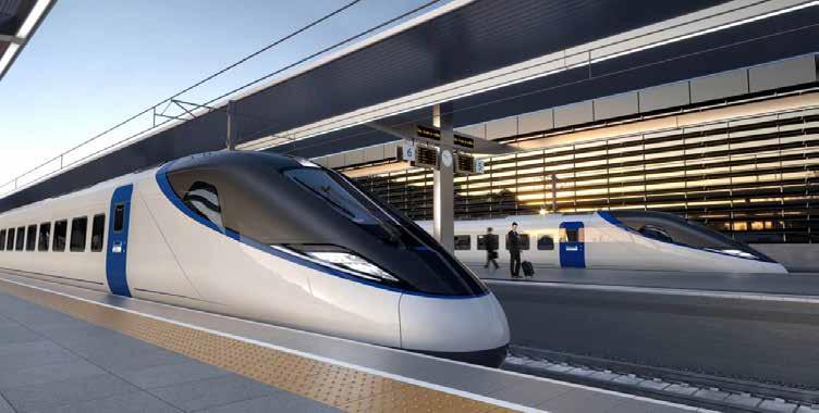
In October, GCRE acquired a fleet of three Class 360/2 EMUs. Built in 2004, these trains previously operated stopping services to Heathrow and became surplus to requirements with the introduction of Elizabeth line services. They will be used to test specific rolling stock systems such as suspension, ETCS, and novel train control. Also, when heavily loaded, unmanned continuous running of these units on the infrastructure test loop, under ATO for 16 hours per day, would provide the required cumulative track loading over a high axle count.
much-needed GCRE facility at what might first seem to be an unlikely site. Although it is an expensive development, for the first time it will enable new modern trains to be tested and commissioned within the UK. This will reduce the costs and speed up the introduction of new trains. It will also do the same for new infrastructure components.
Kelly Warburton reinforces these points by noting that “GCRE will act as a technology innovator, accelerating innovation, reducing costs, improving the passenger experience, and addressing challenges of decarbonisation.”
Class 360/2 operating Heathrow Express service.
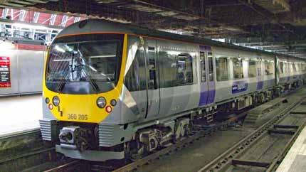
A range of consultants and contractors including Walters, Atkins, Fifth Studio, Arcadis, Mott MacDonald, and SLC Rail are working in an alliance to design and construct the GCRE facilities. Work started in November with the intention that the storage sidings at Onllwyn will be operational by summer 2023 to provide GCRE with its initial revenue.
Track laying is expected to start in 2024 with GCRE becoming fully operational by mid-2025. It is hoped that GCRE will be used for the testing and commissioning of the
The Welsh Government is to be congratulated for having the vision to develop the
At this challenging economic time, it is to be hoped that funding can be secured for this worthwhile investment.
44 Rail Engineer | Issue 199 | Nov-Dec 2022 PERMANENT WAY & LINESIDE ASSETS
PHOTO: SUNIL PRASANNAN
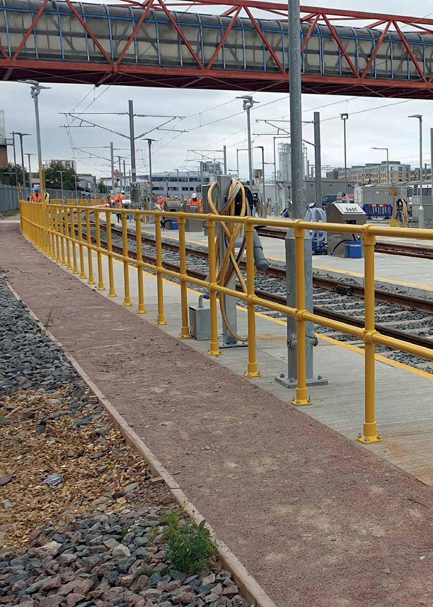

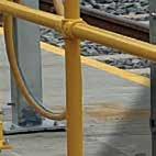





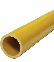


Platform, Depot & Trackside GRP Access Solutions GRP Walkways GRP Hand Railing GRP Catch Pit Covers GRP Embankment Stairs GRP Access Equipment GRP Maintenance Platforms GRP Roof, Track & Cess Walkways GRP Vehicular & Pedestrian Trench Covers GRP Platform Gates, Steps, Ramps & Fencing for the RAIL INDUSTRY Step on Safety www.steponsafety.co.uk 01206 396 446 GRP - THE LONG-LASTING, LOW-MAINTENANCE ALTERNATIVE TO STEEL
Innovative GCRE Construction Competition
DAVID SHIRRES


Innovate UK drives economic growth by supporting businesses to develop new ideas. It does so by connecting businesses to those that can help them and by providing funding. Since 2007 it has funded around 11,000 projects which, with industry matched funding, have a value of over £4.3 billion. This is estimated to have created 70,000 jobs and generated £18 billion in added value to the economy.
One way of providing this funding is through open competitions of which the latest is a £7.4 million competition to encourage innovation in construction of the Global Centre of Rail Excellence (GCRE). This is being funded by the Department for Business, Energy, and Industrial Strategy (BEIS).
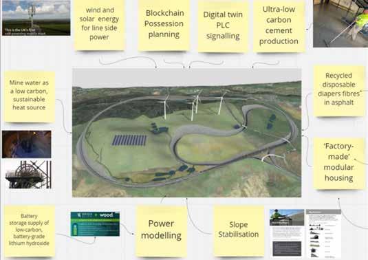
BEIS funding
This competition was launched at an event in Cardiff on 3 October at which companies were invited to hear how they could enter. Speaking at this event, Mike Noakes, BEIS’s head of rail explained that his department was funding this railway competition as constructing GCRE addressed the BEIS priorities associated with innovation, upskilling, net zero, levelling up, and stimulating economic regeneration.
He also explained that BEIS sought to provide the supply chain with what it needs to do its job. He feels that the high-quality railway supply chain has the potential to be enormously innovative. Yet it is constrained by insufficient UK testing facilities. As a result, suppliers must go to the Czech Republic or take chunks of the network out of commission to test their products.
GCRE will provide the required facilities and will also promote innovation. Hence it makes sense to build in innovation as it is being built. Mike considers that the ideas from this competition should be relevant to railways around the world and thus this was the beginning of an export opportunity. He also feels companies will be attracted to GCRE when its testing and research facilities are provided.
Innovation opportunities offered by GCRE.
46 Rail Engineer | Issue 199 | Nov-Dec 2022 PERMANENT WAY & LINESIDE ASSETS
He noted that this had happened at the automotive technology hub of Silverstone Park which now generates millions of pounds of revenue.
Kelvin Davies is Innovate UK’s lead technologist for rail and is currently seconded to GCRE. He noted that, to date, Innovate UK’s rail-related competitions had been funded by the Department for Transport (DfT) with the aim of improving the railway and that this competition is funded by BEIS as its focus is growing the economy.
Explaining the competition
The competition is intended to help make industry more competitive and to reduce capital costs for railway construction at GCRE, and globally. Hence, entrants must demonstrate, for example, how their innovations will reduce whole life costs, reduce timescales, or result in more efficient materials handling or efficient use of resources.
It has two phases. The first is the production of a feasibility study with plans to demonstrate innovation in railway construction whilst
working with the teams building GCRE. Entrants who produce a successful feasibility study will then be invited to a phase 2 competition for a much larger grant to deliver and demonstrate their innovation at the GCRE site.
Kelvin considers that the real prize is an innovation that works on the whole railway. He feels that the prize was not just a funding opportunity but an invaluable opportunity for a company to showcase its product at what will become a new railway technology hub.
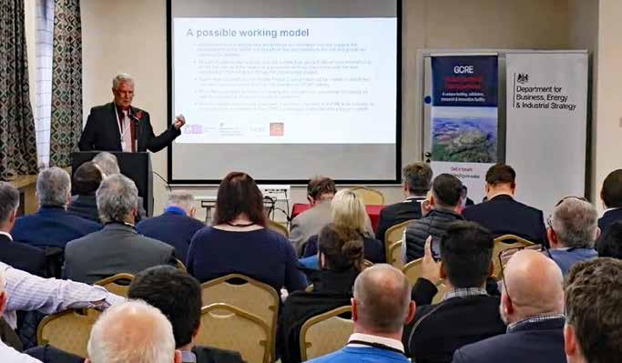
Entrants will have to ensure that their innovation addresses one of the following themes: trackwork; OLE; earthworks and structures; power supply infrastructure; telecommunications; perimeter and cyber security; monitoring and maintenance; railway operation and automated systems; or ecology and habitat creation. Kelvin advises that a portfolio approach will be taken when choosing successful applicants, so the aim is to fund at least one project in each of the nine themes.
Contracts to be let by GCRE.
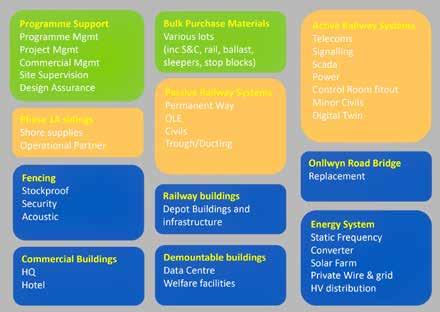 Kelvin Davies explains the competition.
47 Rail Engineer | Issue 199 | Nov-Dec 2022 PERMANENT WAY & LINESIDE ASSETS
Competition plan.
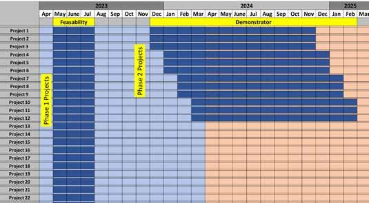
Phases 1 and 2
Competition entrants will first be bidding for the opportunity to take part in phase 1. This is a series of three-month feasibility studies with a maximum cost of £40,000 that start in May 2023, and for which funding of £575,000 has been allocated. This is for 23 studies each funded by £25,000. As a percentage of total cost, the grant given is between 50% for large organisations and 70% for small organisations.
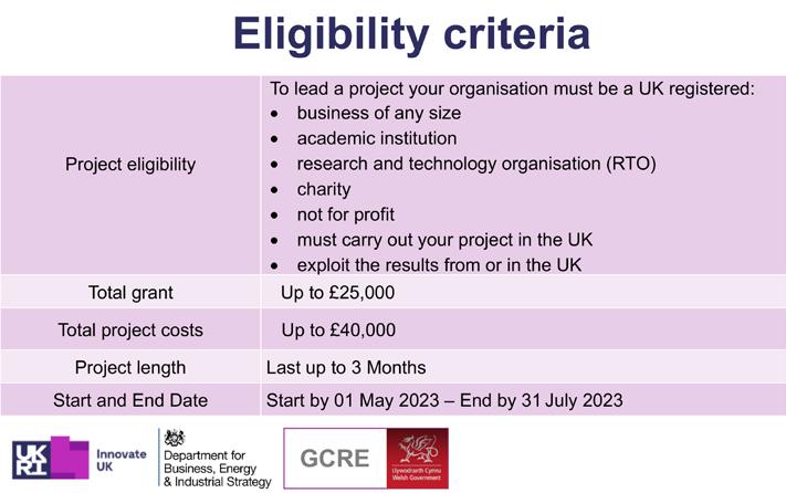
The feasibility study is a stepping stone to phase 2. Hence, it must describe how proposed innovations are to be delivered at the GCRE. This must include details of the working relationships with the
lead construction teams which BEIS and GCRE will introduce to the competition entrants. Phase 2 projects will start around early 2024, depending on the construction activity concerned. These will be delivered by the teams invited to enter the phase 2 competition because of their successful feasibility studies. Funding of £6.8 million has been allocated for phase 2. This is for a nominal 12 projects each with a grant of £575,000 with matched funding up to £0.8 million to £1 million per project. The exact number of projects funded depends on the grants awarded to the phase 2 winners. Hence Kelvin pleaded entrants not to bid
for higher level funding than necessary.
The phase 2 projects must have a demonstration event, for which teams must obtain the required permissions and approvals, as well as an evaluation activity to assess the innovation’s commercial impact on the railway network. It is also a competition condition that the technology concerned must be left on site as part of an extended test and demonstration exercise.
The competition closed on 14 December and applicants will be informed whether they have been successful on 27 January.
Rail Engineer looks forward to featuring the successful applicants.
48 Rail Engineer | Issue 199 | Nov-Dec 2022 PERMANENT WAY & LINESIDE ASSETS
Radio Based Limited Supervision

One of the features and benefits of rail is the very energy efficient, low friction, steel wheel on steel rail interface. This does however mean it is difficult to stop a train, especially within the distance a driver can see ahead, resulting in the need for railway signalling and, in particular, train warning and protection systems.
The latest initiative by Network Rail is Radio Based Limited Supervision (RBLS). RBLS will supplement the Automatic Warning System (AWS) and Train Protection and Warning System (TPWS), until fully Automatic train Protection (ATP) via European Train Control System (ETCS) is rolled out.
For many years, AWS has been provided to warn drivers of caution and stop signals. AWS gives a warning that the associated signal is not green and applies the brakes if the driver doesn’t acknowledge the warning. A drawback with AWS, however, is that there is no distinction between stop and caution signals. Drivers running on consecutive ‘double yellows’ receive a series of warnings, which can make cancelling the warning an automatic reaction without acknowledging the signal aspect.
Clapham Junction
Following the Clapham Junction train crash in 1988, one of the recommendations was to provide ATP throughout the GB network. ATP systems take into account the state of the signals, speed restrictions, and gradients, and constantly supervise train speed, intervening if the driver attempts to drive faster than the safe speed. British Rail instigated trials of two systems on the Chiltern Line and on the Great Western route between London and Bristol. However, it was established that the cost and benefits of fitting ATP to the national network could not be justified.
Signals past at danger (SPADs) were still a serious safety hazard however, and so the Signals Passed At Danger Reduction And Mitigation (SPADRAM) project was set up. It was identified that most SPADs were caused by drivers leaving it too late to brake and passed the signal by a short distance. These usually have no consequence, as signalling design considers the possibility that a train may not stop where it should, and signals are sited with a protective ‘overlap’ before the fouling point.
The relatively simple and costeffective TPWS was therefore developed to instigate a brake activation and to mitigate the consequences of a SPAD. Signals protecting junctions would be fitted with a train stop and speed controls. So, if a train was approaching a stop signal at an excessive speed, TPWS would react with an emergency brake application.
Limitations
TPWS has been a great success in reducing and mitigating SPADs. The lower cost and simplicity of TPWS meant that nationwide implementation was more rapid than nationwide roll out of ATP would have been, and TPWS has prevented incidents which would probably have had consequences similar to Ladbroke Grove. However, TPWS does not cover all driver errors.
The purpose of TPWS, where TPWS track equipment is fitted, is to automatically initiate a brake demand, if the


Rail Engineer | Issue 199 | Nov-Dec 2022 49 PERMANENT WAY & LINESIDE ASSETS
PAUL DARLINGTON
train has: (i) passed a signal at danger without authority; (ii) approached a signal at danger too fast; (iii) approached a reduction in permissible speed too fast; or (iv) has approached buffer stops too fast.
A TPWS installation consists of an on-track transmitter adjacent to a signal, activated when the signal is at danger. A train that passes the signal will have its emergency brake activated. If the train is travelling at speed, this may be too late to stop it before the point of collision, therefore a second transmitter may be placed on the approach to the signal that applies the brakes on trains going too quickly approaching the signal at danger. This is positioned to stop the majority of trains approaching at up to 75mph (120km/h).
The train protection risk reduction capability of TPWS has proven to be higher than originally envisaged, but the residual risk considerations between the capability of TPWS and ATP (ETCS) include that not all signals are fitted with TPWS and not all trains are able to be stopped before the conflict point, even at fitted signals. Not all Permanent Speed
Restrictions (PSRs) - including lower speed turnouts - are protected with TPWS and the protection arrangements are limited. Temporary and Emergency Speed Restrictions (TSRs and ESRs) are also not fitted with TPWS and TPWS is not a failsafe design system. It was always intended as an interim arrangement until ETCS with ATP was provided.
RBLS
The need for RBLS was prompted in 2019 around the time of the anniversary of the Ladbroke Grove crash, when two passenger trains collided almost head-on after one of them had passed a signal at danger. RBLS centres on the train protection residual safety risks between TPWS and ATP delivered by ETCS.
Currently, the roll-out of ETCS is extended to that envisaged when the strategy of TPWS as an interim train protection strategy was adopted. The GB Long Term Deployment Plan also highlights that TPWS will still be operational on some routes in 40 years’ time. So, it was identified that a way was required for the GB rail system to manage the identified train
protection residual risk, So Far As Is Reasonably Practicable (SFAIRP), prior to the full roll out ETCS ATP. The result was RBLS.
RBLS cab indications will provide updates of signal status to ensure speed supervision profiles are at all times aligned with signal aspects and are such that the infrastructure safety envelope is not exceeded. RBLS will also allow trains with higher braking capabilities to pass double yellow signals and delay braking – improving signalling headways with no repetitive AWS cancellations.
The RBLS architecture could use ETCS onboard systems or a specific RBLS onboard system for fleets not envisaged to be fitted with ETCS onboard – these could use Global Navigation Satellite System (GNSS) with other measures for their positional reference. In addition, the architecture could include ETCS Radio Block Centre (RBC) with RBLS capability, TSR and ESR data, and topographical and static speed profile data – which for the specific RBLS onboard solution using GNSS, would be downloaded to the train by a Track Map system.
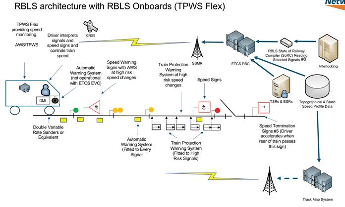
Rail Engineer | Issue 199 | Nov-Dec 2022 50 PERMANENT WAY & LINESIDE ASSETS
OTTO
The Optimised Train Track Operations (OTTO) concept is a set of systems and railway configurations derived from the RBLS concept that have the potential to deliver safety, operational efficiencies, and performance benefits, linked to business needs of the existing network ahead of ETCS deployment.
The OTTO concept has the potential to address safety issues faster than is possible through ETCS deployment. These safety issues include: overspeed, track worker, possession management, and level crossing (footpath and user worked crossing). OTTO also has the potential to provide SPAD mitigations and performance benefits with the braking capability of trains maximised, resulting in less restrictive aspects, which is also a safety benefit. The OTTO concept will be modular in design such that the system configuration can be aligned to the business needs of a route section/train operator and will consist of a number of systems/ configurations:
Speed Restriction Management System (permanent/ temporary/ emergency) to facilitate the application of ‘zero speed restrictions’ required for track worker protection, possessions management system, and level crossing management.
TPWS Flex+ (RBLS specific onboard with Driver Machine Interface - DMI). This will use GNSS geospatial positioning to provide autonomous vehicle location (similar to a car SATNAV). Information will be provided to the driver of the speed restrictions applicable or approaching and will continuously monitor the train speed and automatically apply the train brakes if going too fast.
Isolated Speed Limited Authority (ISLA) - enhanced RBLS train positioning system. This will be independent of the signalling system and will consist of a Track Map server to provide the speed information to the TPWS Flex+ system. It will connect to Network Rail’s Network Model (Axiom) to provide topographical information and to the speed restriction management system for information on speed restrictions.
OTTO Overlay (RBLS state of railway compiler) – will provide ETCS functionality that can be interpreted by TPWS Flex+ (and ETCS) fitted trains. It will connect to the signalling system by a simple interface and facilitates SPAD protection plus speed limit control for diverging routes. The OTTO overlay also improves SPAD management by ensuring that all trains will be able to stop before conflict points.
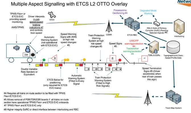
The business case
The initial business and safety analysis has concluded that OTTO has the potential for extracting business benefits (including safety benefits) to GB rail if all trains are retrofitted with TPWS Flex+ and the majority of infrastructure with ISLA, and to fit ETCS Level 2 with no signals for all conventional signalling renewals when all trains on the route section are fitted with TPWS Flex+ or ETCS.
The technologies associated with OTTO are still at concept and early development phases. The full benefits will not be realised until at least the end of Control Period 7 (2029) and need to be aligned with TPWS Flex+ fitment.
The OTTO strategy has the potential to be the ALARP solution for the migration to ETCS based on the early system benefits associated with the ISLA/TPWS Flex+ configuration, therefore further development activities including ALARP safety analysis and more detailed business analysis, and operational trials are being undertaken. However, until such time as OTTO can demonstrate maturity on an operational railway, the base case is to maintain the current ETCS programme supporting the Control Period 7 and 8 renewal plans (2024-2034).
Many thanks to Andrew Simmons, Head of System Authority Network Rail for his assistance with this article.
Rail Engineer | Issue 199 | Nov-Dec 2022 51 PERMANENT WAY & LINESIDE ASSETS
FFU crossings and sleepers
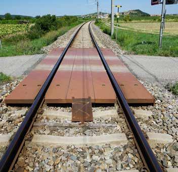
In the past, agricultural level crossings on branch lines were usually constructed from wood. Weathering effects and the high demands of agricultural and forestry vehicles and equipment, mean that these wood constructions have relatively short lifespans.
In contrast to wood, (Fibrereinforced Foamed Urethane (FFU) synthetic wood is based on a near-non-porous material. It does not absorb moisture, not does it require chemical treatment which can be harmful to the environment. It is also weather-resistant.
These aspects increase the safety of crossings and offer longer maintenance-free functionality. In addition to the high life expectancy of FFU synthetic wood, it can be fully recycled too.
Many crossings have already been built using synthetic wood in Japan, Austria, and, since 2022, also in Great Britain. In 2022, Network Rail installed its first FFU crossings, meeting the standards of BS EN 19912-:2003: Action on Structures – Traffic loads on bridges. Furthermore, the required surface safety for walking and driving on these crossings also had to be approved.
Together with Network Rail, the FFU level crossing pieces were designed so that each of them can be easily handled by two people, meeting Network Rail’s health and safety regulations.
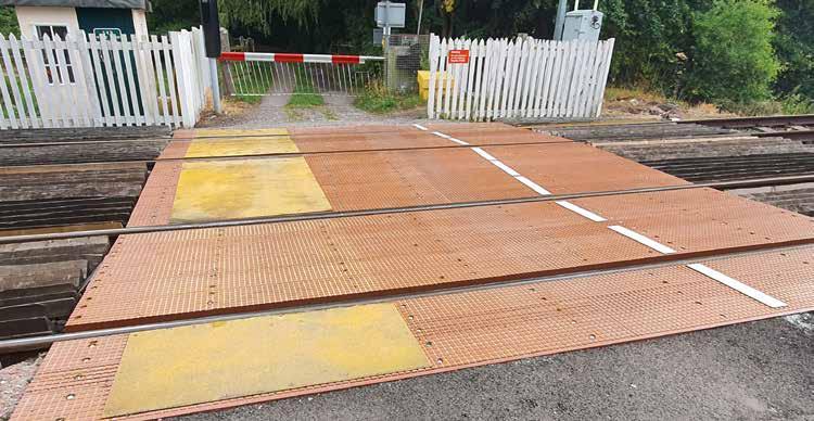
Why FFU?
In the 1970s, the Japanese Railway identified that the life expectancy of the wooden sleepers it was using was noticeably short, primarily because of environment exposure. As a result, the Japanese Railway wanted to manufacture railway sleepers with the same material properties as their wooden counterpart, but which could withstand the region’s climatic conditions. Sekisui, in partnership with the Japanese Railway, developed FFU in 1978.
FFU synthetic railway sleepers are produced by the pultrusion process (Fig. 4), in which the base material of the sleeper is created by drawing the individual material components through a moulding casing. Continuous surface-optimised glass fibres are drawn precisely into the moulding casing, and a special polyurethane composite is added in the moulding channel which moves along with it. This saturates the very dense glass fibres completely and non-porously. A precisely controlled temperature, and a closely-monitored draw speed guarantee a very high and durable material quality.
The finished FFU strand is continuously extracted at the other end of the casing
52 Rail Engineer | Issue 199 | Nov-Dec 2022 PERMANENT WAY & LINESIDE ASSETS
channel and monitored as it is cooled. It is then cut to the required length and checked again for its quality.
Customised production
This technology offers the advantage that sleepers can be manufactured in almost any shape produced just as precisely as wooden sleepers. This applies, for example, to sole plates, which can be produced from a height of as little as a few millimetres up to a length of 16m, width of 70cm, and height of 35cm.
The synthetic wood can be worked with on the track in the same way as natural wood using high quality tools. On request, pre-prepared drillings precise to the millimetre, processing of any kind, doubling, numbering and much more can be carried out in the factory.
Sleepers can be specially produced depending on the project. Cambers in curve areas, milled grooves for support bearings, holes, and much more, are precision premanufactured in the factory according to customer requirements. The sleepers are
numbered according to the plan, stamped with the production period, and delivered to the construction site for installation.
Built dimensions
On mainline railways in Europe, sleepers with a construction height of 10cm, width of 26cm and length of 2.6 metres are used, especially on bridges with ballast tracks and on regular tracks at points where the ballast thickness under the sleepers can be maximised by this. Points sleepers of length up to 9.6 metres have also already been installed in Japan and other sleepers around insulated rail joints with a width of up to 60cm in one piece are in use.
For trains, trams, and underground railways, the minimum constructed height is 10cm. Areas where these are used are light and heavy mass-spring systems, direct fixings on bridges, and on points on ballast tracks.
Longitudinal sleepers in a single piece of dimensions of up to 70cm width, 16m length, and 35cm height have been installed on the British and Irish networks on points and bridges.
percent by volume ratio of glass fibres in the cross section of the FFUrailway sleeper.


Herstellungsprozess FFU 1 2 Glass fibres distribution Glass fibres impregnation moulding Cooling pultrusion cutting Finishing and inspection
50
53 Rail Engineer | Issue 199 | Nov-Dec 2022 PERMANENT WAY & LINESIDE ASSETS
FFU Synthetic Wood Railway Sleeper Manufacturing Process.
Recycled FFU production waste (K-FFU) between FFU sleeper and thrust bearing.
Recycling/sustainability
The first sleepers, installed in 1980, are still in safe use. As yet, there has been no need to recycle any of these sleepers.
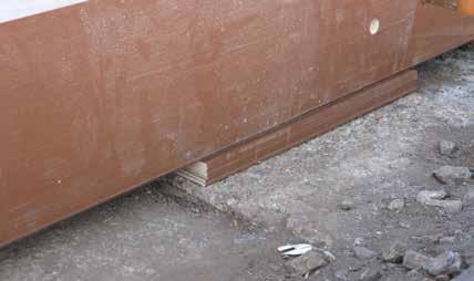
Any waste from the manufacturing process comes in the form of drilling waste dust, chippings from milling, and sanding. One hundred percent of this waste is recycled. The manufacturer also guarantees that it will recycle all synthetic sleepers at the end of their lifetime and create new products out of them. For example, FFU in the form of so-called K-FFU, is made from manufacturing waste and has been used in projects in Austria as sole-plates in bridge abutment wall bearings with a constructive height of a few millimetres (Fig. 6).
Sekisui’s environmental credentials have been recognised by industry bodies, globally. In early March, the company received the Bronze Award at the third ESG Finance Awards in Japan, hosted by the country’s Ministry of the Environment. Sekisui took the award in the Environmentally Sustainable Company category. It was recognised for integrating environmental issues into its business strategy, its high awareness of environmental issues in promoting (ESG) management, and its planning and implementation of a medium-term environmental plan.
In February, Sekisui was given a “Silver Class” sustainability ranking by S&P Global, a global ESG investment investigation and ranking company, and in
January it was selected as one of the 2022 Global 100 Most Sustainable Corporations in the World, by Corporate Knights Inc. The Canadian company recognised Sekisui’s efforts towards a sustainable business based on environment, society, and governance. Sekisui has also been selected for 10 consecutive years by the World Index of the Dow Jones Sustainability Indices (DJSI) and has attained the highest rank in the Development Bank of Japan’s Environmentally Rated Loan Program, in recognition of its environmentally conscious initiatives.
Advantages of using FFU
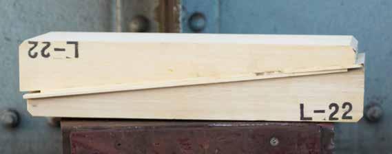
A Life Cycle Cost analysis by the Graz University of Technology shows a possible rate of return of up to 25% when using FFU on Deutsche Bahn’s steel bridges. As mentioned, the technology has been in use in Japan since 1980 and, in 1985, Japan’s Railway Research Technical Institute (RTRI) forecast a life expectancy of 50 years or
1.7 billion tonnes of load. This forecast was reconfirmed in 2010 when sleepers that had been in use for 30 years were examined by RTRI.
In terms of safety, experience and references, this technology has been used on more than 1,800km of installed equivalent track (mainly on bridges and at points). The gauge remains safe due to the strength and the low thermal expansion coefficients. The linear elastic properties of FFU are guaranteed to -65 degrees Celsius.
Safety on the tracks
Experience with a wide variety of synthetic sleepers in the railway sector has shown that the various technologies differ considerably in terms of quality, technical characteristics, and the behaviour of the technical materials used. For this reason, by classifying the materials into types, specialists from operators of rail networks in many countries have presented these differences in a manner that is practical for the ISO Standard 12856-1 for synthetic sleepers.
Sekisui’s FFU sleepers have been successfully used in continuous operation on rail networks for over 42 years. The patented construction method guarantees the highest level of safety and reliability in daily use on railway tracks. In many countries all over the world, FFU synthetic wood has set the standard for the reliable use of synthetic railway sleepers on bridges, in points and in tunnels.
London Underground Chiswick Park, FFU wedge and layer pads.
54 Rail Engineer | Issue 199 | Nov-Dec 2022 PERMANENT WAY & LINESIDE ASSETS
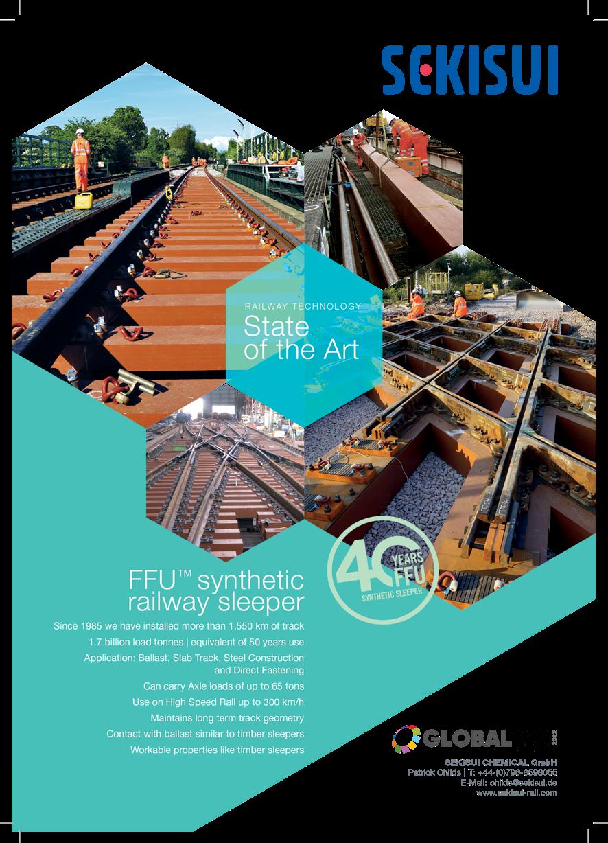
alternativeAn
TO INSTALLING PANTOGRAPHS WITH 200MM CLEARANCES
The 2019 Railway Industry Association electrification cost challenge report assessed the successes and failings of electrifying the Great Western Electrification Programme (GWEP). Its opening statement stated that the cost of electrification was increased due to factors including “unpreparedness in using novel technologies resulting in poor productivity”. New technologies may seem daunting to the railway; however, the adoption of these techniques is key to adapting, remaining efficient and making improvements.
One such technique is probabilistic gauging. Whilst absolute gauging is safe, tested, and consistent for the railway, this conservative approach can waste millions in unnecessary work. With improvements in dynamic vehicle modelling and up-todate survey data, gauging is becoming closer to reality than ever before and so offers significant opportunities to reduce both the cost of electrification and gauge clearance work for rail freight. Currently the UK rail network has few routes that can accommodate container trains. Clearing additional routes for such trains is essential if such inter-modal rail freight traffic is to be increased.
Regarding electrification, clearances through our infrastructure are still too tight to safely offer 200mm of clearance between the pantograph and the infrastructure. D/Gauge engineers are well versed in the tolerances and conservatism that are incorporated into absolute gauging to keep the railway safe, but on the second inspection, how can we confidently reduce the space between the OLE and the vehicle, without comprimising safety?
The accident-free history of rolling stock indicated that tolerances are preventing strikes, however it also may indicate differences in expected clearance outcomes in practice versus conservative calculations. Digital simulation is
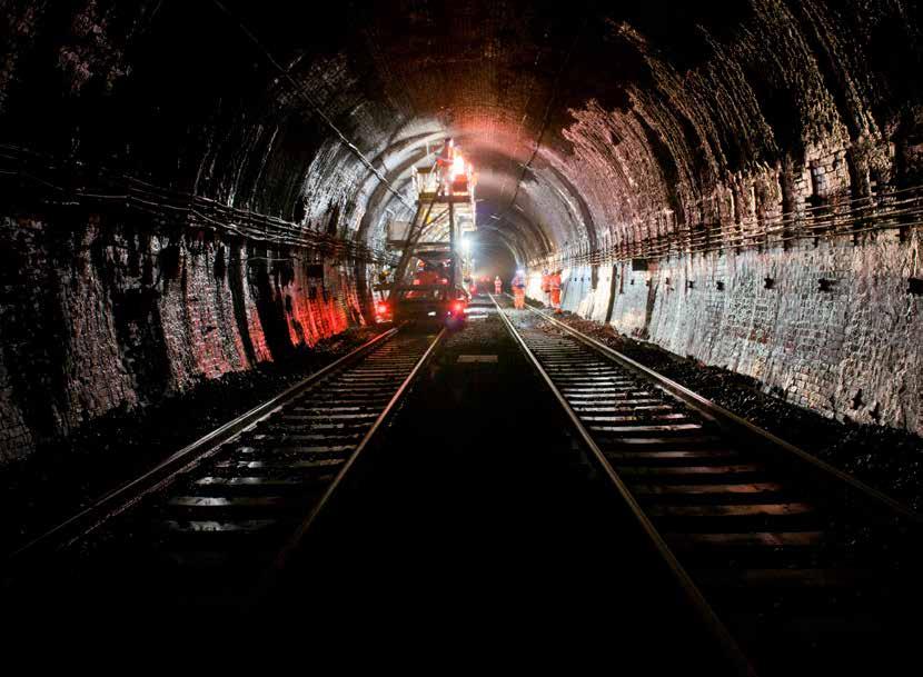
a strong indicator of the vehicle movements, track conditions, and location of OLE equipment. In practice, the track moves over time, rails and wheels wear over time, and loading conditions vary. Tolerances are accommodating for these variations and work to the safest possible outcome.
By assuming that every single element will not be in its worstcase scenario (as is assumed for absolute gauging), secondary analysis can determine more representative in-life clearance outcomes. Rather than use a conventional rulebased approach to gauging, probabilistic pantograph gauging is linked to a ‘Monte Carlo’ event generator which generates ‘events’ where all tolerances are within their prescribed bounds, and which occur within their probability distribution. Alongside the rapid calculation of clearance, we can undertake 10,000 or more simulations and quickly generate probability distributions of the resultant clearances that would occur over this representative lifetime.
Rail Engineer | Issue 199 | Nov-Dec 2022 56 PERMANENT WAY & LINESIDE ASSETS
As an industry, we choose to take safe, less risky decisions. Balancing risk versus uncertainty is not easily done and changing the status quo can only be done after a thorough investigation and analysis of the consequences of doing something different. To make probabilistic pantograph gauging a success, the industry had to have assurances that new, innovative methods of approaching electrification will not affect risk or safety on the railway.
RSSB commissioned two research projects (T373 – “Uncertainty in Structure Gauging” and T670 – “Investigation of the accumulative effect of vehicle tolerances on gauging”) which specifically analysed “uncertainty analysis”, to investigate tolerances in a mathematically correct manner. The reduction of uncertainty considered how individual tolerances varied, and how they were accumulated as part of a system.
Network Rail Scotland Successes
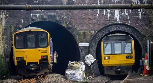
Since its roll-out with Network Rail Scotland, probabilistic pantograph gauging has reduced the cost of electrification by avoiding bridge reconstructions and so supports the drive to make electrification affordable. A probabilistic pantograph gauging sweep across circa 560 structures in Scotland used modern, probabilistic engineering methodologies to establish where tighter clearances pose actual risks. Combined with VCC overhead systems, (which were extremely successful in the 2018 Andromeda test with Network Rail Scotland), the technologies have reduced the cost of electrification by £187,000 per single track kilometre or £300 million for Scotland’s planned electrification programme which will decarbonise Scotland’s Railway by 2035. Thus probabilistic pantograph gauging brings the business case cost for electrification down and should be used to reassess the real cost of electrification on the rest of the UK network.
Alan Ross, Director of Engineering and Asset Management for Network Rail shared the huge cost savings at the April 2022 PWI conference in Glasgow.

The future of gauging for electrification
Probabilistic pantograph gauging is a comprehensive methodology, specially developed by D/Gauge. Absolute gauging is just as accurate as probabilistic, but its specialism lies in ensuring a higher level of safety and/or demonstrating areas of the network which have no tight clearance spots and OLE can be installed without any considerable disruption or additional costs.
The power of probabilistic lies in assessment in the tight sectors of the UK, where electrification schemes are failing to gain the capital investment to kickstart electrification, or fears of extensive infrastructure works grind work to a stalling stop before they even begin. By utilising the power of novel technologies, more schemes can be reinstated and progressed to move towards the overall goal of electrifying the whole UK Railway.
About D/Gauge
D/Gauge is a 30-strong team dedicated to clearance, including some of the UK’s most celebrated experts in gauging. Its expertise lies in software development, data management, and project consultancy. In 2021 it delivered over 180 projects and over its short history it has worked for 110 clients across the globe.
57 Rail Engineer | Issue 199 | Nov-Dec 2022 PERMANENT WAY & LINESIDE ASSETS
Dr David Johnson, Technical Director of D/Gauge has been pivotal in gaining acceptance for probabilistic pantograph gauging in the railway.
BOB HAZELL


The impact of hot weather on British railway plain line track
Plain line railway track construction is designed to resist the operational forces associated with passing trains and the forces and impact associated with the prevailing weather conditions. However, as global temperatures increase, more of the current track construction types get closer to the Critical Rail Temperatures (CRTs). This then starts to impact on the track’s stability in very hot conditions.
Steel rails expand as they get hotter and contract as they cool down. The coefficient of expansion (how much it expands as it gets hotter) of normal grade carbon steel, commonly used in the manufacture of rails, is 0.0000115 per °C. Manganese steel rail, a harder wearing steel used in limited amounts has a coefficient of expansion of 0.000018 per °C, which is some 56% greater than that of normal grade steel.
Air temperatures in Britain this summer broke all-time records reaching 40°C in Lincolnshire on 19 July. Rail temperatures on hot days with no wind or cloud cover can reach 20°C or more above the air temperature. This resulted in rail temperatures in the high 50s °C.
Typical rail temperatures in the UK have normally varied from -15°C, some winters lower, to 55°C. This resulted in a typical overall temperature variation of 70°C. This variation, and the resultant rail expansion and contraction must be safely accommodated in the track design.
Based upon the above temperature ranges, in theory, the West Coast Main line between London Euston and Glasgow Central is 540 metres longer on a hot summer day than it is on a cold winter’s night. Of course, the distance between London and Glasgow doesn’t vary, so how is the expansion and contraction accommodated on this, and all other routes, and what does the increasing risk of higher rail temperatures mean for the track engineer?
Jointed track
The management of thermal expansion and contraction of rails was historically dealt with by creating a joint with a gap between each rail. The normal length of rails in jointed track on the UK network was and still is 60ft (18.288 metres), although longer lengths, up to 120ft and shorter rails exist. The joints, at 60ft intervals, results in the classic clickety clack noise as trains passed over them.
Jointed rails are joined by fishplates, of which there have been various designs. The fishplates and fishbolts in jointed track were designed to allow contraction of the rails in cold weather and expansion in hot weather, without the rails and track becoming distorted and buckling. Typical examples are shown in the photo below. The diagram below shows the typical dimensions of the fishbolt holes in the rail and fishplate, as well as the fishbolt diameter.
Based upon a 70°C rail temperature range, a 60ft rail will expand and contract by 15mm. Correctly manufactured rail joints can allow
Rail Engineer | Issue 199 | Nov-Dec 2022 58 PERMANENT WAY & LINESIDE ASSETS
approximately 11mm expansion, therefore, at the hottest temperatures the rail in jointed track is in compression, and at the coldest temperatures the rail and joints go into tension. The colder temperatures induce forces on the bolts, fishplates as well as on the fishbolt holes in the rails.
Jointed track, and the joints themselves are labour intensive to maintain, particularly in terms of preparation for hot and cold weather. The rail joints require annual lubrication, which involves removal of the fishplates, inspection of the rail ends for any signs of visible cracking, lubricating the underside of the railhead and upper part of the rail foot (the fishing surfaces) that contact the fishplate, and then replacing the fishplates and bolts, tightening them up to the correct torque.
Ultrasonic testing avoids the need to remove the fishplates to detect cracking of the ends and fishbolt holes in the rails. Developments in lubricants by companies such as Interflon, mean that fishplate lubrication can be carried out without the removal of the fishplates. Whilst these developments reduce some of the maintenance requirements, some rails in jointed track can creep along, generally in the direction of traffic.
This creep causes bunching of the rails and the closing up of the expansion gaps. The gaps require monitoring and measuring and, if too many consecutive rail expansion gaps are closed up in the cooler weather, the rails and rail gaps need to be adjusted, regulating them, so that the correct expansion gaps are available before the onset of hot weather.
Track buckle in jointed track
Failure to carry these maintenance tasks out can result in the jointed track buckling. An example of a track buckle in jointed track is shown in images on this page.
As global temperatures rise, the focus on the correct maintenance of jointed track becomes even more critical if track buckles of this track form are to be avoided. Even minor deficiencies, including that of the ballast profile, can result in a reduction in the critical rail temperature which, in turn, results in the risk speed restrictions being applied to limit the track forces applied.
Track ballast
Both jointed and continuously welded track rely on track ballast for the stability of ballasted track. The angular nature and interlocking of the ballast provide frictional resistance to both the underside (soffit) and sides of the sleepers. The frictional resistance increases as the ballast and sleepers consolidate themselves due to the repetitive loading from rail traffic. The increased consolidation results in an increase of the calculated CRT. If track is disturbed, typically by tamping or activities that disturbs the ballast, the frictional resistance is reduced.
This frictional reduction results in a reduction in the CRT. It is essential, therefore, that track is not disturbed in, or just before the onset of hot weather. If ballast must be disturbed, the calculated CRT must be adjusted (lowered) and any necessary mitigation, such as speed restrictions to reduce the impact forces on the track, applied until sufficient traffic has been carried to fully consolidate the track and ballast. On-track machines with dynamic track stabilisation (DTS) can be used to accelerate the consolidation of the track and ballast and increase the CRT. DTS machines can be used to reduce the risk of speed restrictions in hot weather but were originally introduced to consolidate newly laid track to allow it to be opened to traffic at higher speeds, up to 125mph.
59 Rail Engineer | Issue 199 | Nov-Dec 2022 PERMANENT WAY & LINESIDE ASSETS
Long welded rail
With the requirement to reduce maintenance, improve ride quality, and increase speeds, developments were made with trials of long welded rail. Initially, bullhead rails were used. These were welded into 300ft lengths with machined tight joint fishplates joining the long welded rail. London Passenger Transport Board started installing long welded rail in 1939. By 1948 some 60 miles of track had been laid on the London Transport network.
In a 1948 paper to the Institution of Civil Engineers, the author Cedric Dunton tentatively concluded the maximum rail length of 1470 feet (448 metres) with a breathing gap between rails of five to nine inches (127-229mm) could be achieved in long welded rail. The breathing gap was achieved with what were then called expansion joints.
Long welded rail reduced the number of joints the maintenance teams had to maintain and helped to improve ride quality, but it still had a significant number of joints and required maintenance input to prepare for the various seasons, especially summer.
Continuously welded rail
The next step was to develop continuously welded rail (CWR). Trials on the mainline railway were undertaken on the Southern Region and in France, but it was not until 1953 that early CWR was trialled and installed on other Regions of British Railways.
In those days the track consisted of softwood sleepers with cast baseplates or chairs, with early pre-stressed concrete sleepers installed on the later trial sites including a site at Llanwern.
The Llanwern site consisted of two sections of CWR track, each half a mile in length. The 300ft rails were further welded on site using the thermic welding process into the full half mile length.
Expansion or adjustment switches were installed at each end of the CWR to allow for expansion and contraction of the end sections of the CWR. These expansion switches also isolated the stresses in the CWR from the adjoining jointed track.
In the early days of CWR, before the development of hydraulic stressors, the rail was heated and expanded to the correct stress-free
temperature using rail warmers before being clipped down to the sleepers. Rail warmers are still used, mainly in complex areas where it is not possible to use hydraulic stressing equipment or where a sufficient stress anchor cannot be achieved, typically in and around switch and crossing layouts.
Today, CWR is stressed to 27°C when it is installed. This is the stress-free temperature (SFT). It is, therefore, in tension at temperatures below this and in compression at temperatures above 27°C.

CWR is delivered to site in lengths of 216 metres on special CWR trains. These lengths of rail are then welded on site making them a continuous string of rails with no expansion joints (some insulated joints may be welded into the string for track circuit signalling purposes). The rail is clipped to sleepers, which tend to be concrete, although timber, steel and plastic sleepers are used in Britain. The heavier concrete sleepers offer good resistance to buckling.
When installed, the rail, before being clipped down to the sleepers, is physically stretched, usually using hydraulic tensors. The extension required is calculated using the difference between 27°C and the actual rail temperature, and the length of free unclipped rail and coefficient of expansion of the steel used to manufacture the rail. To limit the effects of friction on the length of free rail during the stressing operation the rail is placed up upon rollers.
There is no maximum limit to the length of rail that can be welded together but there are limits on the length of rail that can be stressed in one go, mainly due to limitations of the stressing equipment and the greater risk of an uneven pull due to snagging of the rail over longer distances, along with the risk on curves that the rail will attempt to straighten itself whilst being stretched. To prevent the rail from pulling in, side rollers, to guide the rail, are installed on curves during stressing. The maximum length of free rail when stressing is 900 metres.
When the correct expansion of the rail has been achieved for the rail temperature, the rollers are removed, the rail is clipped down to the sleepers and welded up with the adjacent rail to form a continuous length.
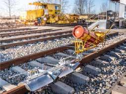
Records are kept of the stress in the rail. The stress achieved during the stressing operation is known as the stress free temperature (SFT). This is normally 27°C but can vary between 21°C and 30°C.
Other, less common methods of stressing the CWR include heating the rail and natural stressing in warm weather. Heating or thermal stressing of rails is achieved by using a heat source that is moved along an unclipped rail until the required rail temperature and expansion is achieved. When the correct temperature is achieved the section of rail at the correct temperature is lowered
60 Rail Engineer | Issue 199 | Nov-Dec 2022 PERMANENT WAY & LINESIDE ASSETS
from rollers and clipped to the sleepers. The operation must be achieved swiftly before the rail starts to cool below the required SFT limit.
Natural stressing can be used, where the sun, or ambient temperature, warms the rail to achieve the required SFT. In this case the unclipped rail is still placed upon rollers but the rail expands naturally without using tensors or heaters. The rail must be clipped down and welded before it becomes too hot in which case the rail becomes overstressed.
Adjustment switches are now generally only installed at interfaces with jointed track and some older switch and crossings layouts that were not designed for the high stresses encountered in CWR.
Rail expansion joints are installed where there is a requirement to isolate the track stresses and longitudinal forces from that of large structures that the track passes over, typically around large span underbridges.

Special precautions
Special precautions are required when replacing rails in CWR. The rail stresses need to be maintained or restored to 27°C. The process is strictly controlled, and records taken of the changes in rail and the stress achieved. If there is insufficient possession time to maintain the correct stress in the rail, and the replacement rail is installed with an SFT significantly below 27°C, plans must be put in place to restress the rail before the onset of hot weather. This is often why, along with sites of any recently disturbed track and any known weaknesses, speed restrictions are applied in hot weather. Speed restrictions reduce the impact forces upon the rail and track which reduces the risk of instability. As global temperatures increase and rails suffer higher temperatures, the risk of speed restrictions increases.
The high temperatures of summer 2022 have seen an increasing number of hot-weather-related speed restrictions applied. In some cases, the sites become so numerous that it is not possible to sign all of the locations on site, so blanket speed restrictions over large areas are applied. The first of these was applied in the summer of 2003, when exceptionally high air temperatures with rail temperatures of 57°C recorded at Tonbridge in Kent caused a blanket speed restriction across much of the Southern Region. Generally, using detailed predicted air temperature forecasts, the sites of these are determined and published days in advance so the train operators can establish the implications on their timetables and this can be communicated to their customers.
In later editions we shall review what can be done and what is being done to make the track more resilient to the increasing temperatures that Britain is predicted to encounter in the future.
61 Rail Engineer | Issue 199 | Nov-Dec 2022 PERMANENT WAY & LINESIDE ASSETS
Light Rail SUMMIT
If one word was used to sum up September’s Light Rail Summit it would be ‘partnership’. The event was held in Manchester, the city where the UK’s first modern generation street tramway was inaugurated in 1992 which now boasts the country’s biggest tram system with 64 route miles of standard gauge track, 99 tram stops, and 147 three-bogie articulated trams.
Unlike any other UK street tramways, Manchester’s trams have a high floor and all stops have high platforms, a feature that has enabled relatively easy conversion of heavy rail lines to tramways and was a feature of the original 1992 system.
UKTram and the Light Rail Safety and Standards Board used the event to report back to members, but other presentations highlighted developments throughout the industry - see also the 2021 summit covered in Rail Engineer 193 (November/December 2021).
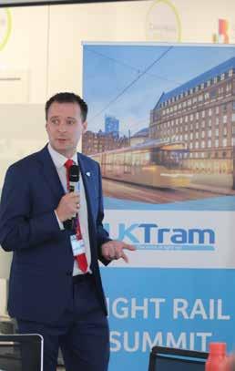

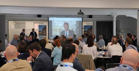
Business plan

James Hammett, Managing Director of UKTram, explained how there is now much better engagement between the light rail industry and the Treasury, Department for Transport (DfT), and Transport Scotland, which is often weekly and with open and honest exchanges of views. This is a major improvement developed over the last couple years.
George Lowder, chair of UKTram, welcomed what was probably the last tranche of government Covid funding: £380 million from DfT and £37 million from Transport Scotland. James added that the Light Rail Strategy for the UK, published in early 2022, had been welcomed by the Government and this, together with a favourable report by the Office of Rail and Road (ORR) had been instrumental in delivering a long-term funding agreement for UKTram and the Light Rail Safety and Standards Board (LRSSB).
James described the priorities in the 202225 business plan which include helping to define the viability for up to seven new light rail schemes; an ambitious decarbonisation/ sustainability agenda both underpinned by innovation and R&D activities; sector growth; and the pursuit of a diversity and inclusion agenda.
MALCOLM DOBELL
62 Rail Engineer | Issue 199 | Nov-Dec 2022 LIGHT RAIL & METRO
James Hammett.
Partnership with young people
Building on diversity and inclusion, James Wingerath, commercial director of Youth Employment UK, presented the results of the Youth Voice Census 2022. This involved 4,000 responses to a survey of 11- to 31-year-olds, together with six regional focus groups to explore issues in their local areas. James presented a bleak picture of the impact of Covid-19, with young people feeling debilitated by mental health issues, the cost-of-living crisis, and political tensions.
The report states starkly that: “…our findings also reveal that we have now 17 years of cohorts telling us that they feel unprepared for their futures and fear that they do not have the work experience, life skills or practical job-hunting skills that they need to progress.”
James encouraged light rail operators to facilitate work experience for school children and to offer opportunities to young people. James also made remarks about many schools’ poor record in preparing their students for work, and it was noticeable that, during the break, James was surrounded by delegates who were also school governors (including your writer!).
Safety improvement
Neil Clark, CEO of Integrated Human Factors Ltd, provided an update of the FOCUS+ system, developed under the Driver Innovation Safety Challenge initiative, which was described in detail at the 2021 Summit. In brief, the aim is to reduce the risk of accidents due to medical or physiological impairment on the part of the driver. This is against the background that only 20% of all rail and road accidents are a consequence of mechanical issues and they are often linked to driver error. Currently, health/fatigue issues are only identified post-event, and FOCUS+ aims to help identify circumstances where errors might occur so that action can be taken before any incident occurs.
FOCUS+ hardware includes a wrist worn device with sensors in contact with the user’s skin. This communicates with a belt worn, or cab mounted, hub with built in GPS and 3/4G comms. Biometric data from the wearer is anonymised and stored in the cloud. This data is processed and machine learning models identify an individual baseline for each wearer. The algorithm can then highlight deviations from the baseline and send green, amber, or red alerts. Neil said that it was important to over emphasise transparent communication to ensure that users trust both the system and how the alerts are used by employers. In terms of progress, Neil said that work had been delayed by Covid, ice storms, and even the stranding of the Ever Given container ship in the Suez canal, but there are now pilots on five sites with a total of 30 volunteers with more users coming on stream.

Safer journeys
Julian Smedley, a former police officer and now operations manager for Keolis at Nottingham Trams, described his team’s work in combatting anti-social behaviour on the outer sections of the tram network. This behaviour was discouraging passengers, and there was an impact of staff welfare with a risk that drivers might refuse to drive through the affected areas. None of this would be good for the system’s reputation, of course. He had had difficulty getting the police
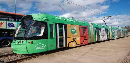
63 Rail Engineer | Issue 199 | Nov-Dec 2022 LIGHT RAIL & METRO
Consent coalition.
interested but the arrival of a new police lead for the area saw a change of attitude.
Julian had called together his organisation, the police, all other transport providers, and Network Rail to pool knowledge and understand what was happening across the modes: “an itch that had to be scratched”, as Julian put it.
Starting in one area, funded police patrols in affected areas delivered great results, dealing with many knife, drug, and county lines related crimes. There was also training for the tramway’s staff on how to identify vulnerable people and what to do if they were found. It was not just enforcement but co-ordinated diversion activity, including working with youth outreach teams such as the Pythian Club which focuses on ‘supporting communities within deprived areas, providing diversionary activities, and constructive pathways’.
This was a great success leading to other community groups becoming involved and an all-over advert in one of the trams featuring the Consent Coalition – 20 Nottinghambased statutory and voluntary sector organisations aiming to raise awareness of consent and reduce sexual violence.
Equally important was keeping the staff involved through the unions, employee support noticeboards and faceto-face meetings.
Manchester update

Danny Vaughan, head of Metrolink for Transport for Greater Manchster/partnership (TfGM), and Guillaume Chanussot, managing director of Keolis Amy Metrolink (KAM), presented current activity beyond merely running a safe and efficient tramway. Guillaume presented a single slide (below) showing all the main partnership activities highlighting significant success, for example, in significantly expanding the network, doubling the passenger journeys to 45.6 million (2019 figure) whilst needing zero operating subsidy (pre-Covid). He pointed to a bright future ahead, whilst highlighting challenges including inflation and HS2. The latter stems from the current plan to sever the line to Ashton-under-Lyme, to the east of Piccadilly station whilst the HS2 station is constructed.
As well as the network’s success as a public transport provider (which your writer evaluated extensively on the day before the event with an excellent value £4.90 off peak day ticket), the presentation turned to the social sustainability and environment agenda. This builds on light rail’s excellent rail credentials with no emissions at point of use.
LRSSB: partnership with operators
The good news is the three-year funding deal following a positive review by the ORR, reported Mark Ashmore, LRSSB’s safety assurance manager. He also introduced Russell Copley from Greenborough who presented the improvements to the Tram Accident and Incident Reporting system (TAIR). TAIR has been vital in developing the light rail sector risk model and
 Guillaume Chanussot.
64 Rail Engineer | Issue 199 | Nov-Dec 2022 LIGHT RAIL & METRO
Manchester Metrolink partnership slide.
continues to evolve. Following a thorough tender process to find a software partner, Synergi Tech Ltd was chosen to help upgrade the system.
The specification was refined to include only the art of the possible and an implementation group with representatives from four operators was set up. Features include single data entry for all accidents, incidents and near misses; programmed data export to any Operating Company systems (e.g. asset management); reduced data input, minimising data errors; real time reporting; and seamless link with the risk model, generally giving greater accuracy and less work. Future developments include full integration of individual network risk models; full integration with the sector’s overall risk model; integration of RIDDOR reporting; and integration of RAIB reporting.
More light rail systems?
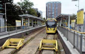
The final presentation –‘Restoring Railways’ - was delivered by Colin Robey, Chair of UKTram’s Centre of Excellence, who, so far, has had a 55-year career in British Railways and light rail. The Centre of Excellence (COE) was set up in 2013, initially to explore reducing cost of light rail schemes following a critical National Audit Office report. Colin reported that the COE’s investigation found that UK trams systems cost no more

than their foreign counterparts and sometimes less.
UK costs seemed higher because the cost of diverting utilities and general works aimed at ‘beautifying the public realm’ were seen as tramway costs in the UK but not in the costs of the foreign systems. Since then, the COE has been helping promoters with their business cases. Often, promoters would come to UKTram with a proposed solution and the COE would patiently help them though the often tortuous route map (likened to a marathon – with hurdles every nine metres) to arrive at the right solution for their particular needs. Inevitably, to have any chance of success, partnership between promoters, politicians, and other stakeholders will increase the chance of success.
Colin said that his group has developed a list of key questions that promoters should answer and, if they can provide positive answers
to at least eight of them, his view was that they might have a chance of making it all the way through the process. The questions cover a full range of issues that potential promoters will be faced with covering: alternative modes, local political support, and financial support throughout from feasibility to operation. The following locations are currently being examined: Bath, Bristol, Stoke on Trent, Isle of Wight, and Folkstone. There will be others.
Colin observed that the current ‘Restore your Railways’ initiative was initially flawed as it focussed on ‘heavy rail’. If these schemes were to be examined more holistically, perhaps including a section of on-street running, they may have more chance of success as they would no longer have to interface with the onerous standards necessary for main line running. UKTram is now invited onto the review panels of those schemes that may have a potential light rail solution.
Finally, and coming back to the route map, Colin observed that the Transport and Works Act, which was intended to make infrastructure works easier to get approved, requires review as it presents endless possibilities for delay caused by what might be described ‘professional objectors’. The COE is exploring how it might be amended and has engaged with the person who drafted it originally.
All in all, another excellent event, and looking forward to 2023.
66 Rail Engineer | Issue 199 | Nov-Dec 2022 LIGHT RAIL & METRO
Media City. Colin Robey.
RailStaff magazine


RailStaff
As well as
developments
• Health • Safety • Wellbeing • Careers and training We also cover stories that
achievements of staff. Such is the freely-distributed magazine’s
the only industry-wide people
the RailStaff
and
Request a free subscription at www.railsubs.com Call 01530 816 444 or visit www.railstaff.co.uk for more information
has been championing the rail industry’s workforce since 1997.
getting to the heart of ‘what you need to know’ each month, its team of writers focus on the latest
in:
celebrate the great
success that
recognition scheme,
Awards, was launched in 2007,
has been held ever since.
Newhaven tram extension ALMOST COMPLETE
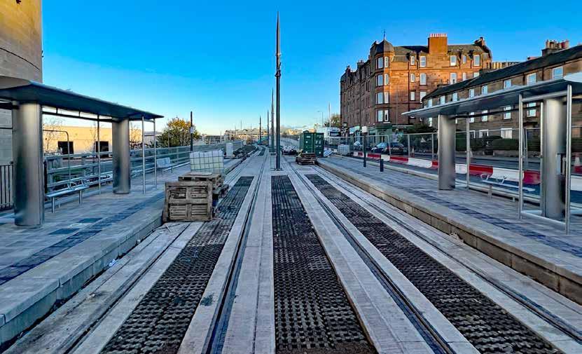
Almost complete Newhaven tram stop.
After many years, Newhaven is soon to get a tram service. Plans for an Edinburgh tram route from Haymarket station to Newhaven were unveiled in 1999. These were further developed into an agreed proposal for a 2006 Act of the Scottish Parliament, which led to the project to construct a 18.5km tram line from Edinburgh Airport via Princess Street to Newhaven. When construction started in June 2008, the line was expected to open in 2011 at an estimated cost of £521 million, including £40 million for the trams.
for the Council to commission a business case for the completion of the original tram project to Newhaven. After this was finalised, the City of Edinburgh Council approved the Newhaven tram extension in 2019 just two years before the expiry of powers to build the extension granted under the 2006 Edinburgh Tram Act.
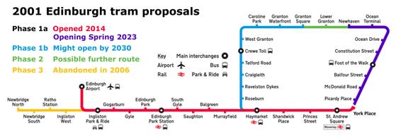
Two contracts


After its well-publicised difficulties, the Edinburgh Tram system opened in May 2014 at a cost of £1 billion for only 75% of the original project. Due to the project’s cost overrun, in 2011 it was decided not to build the city centre-toNewhaven section despite much utility work being done along this part of the route.
By 2014, trams were a toxic subject in the city due to the project’s excessive cost and delays, with associated extended disruption. Yet when the trams started running that year, they proved to be popular, with ridership well above original predictions. Perhaps surprisingly, it then became politically acceptable
In March 2019, the Council awarded two contracts for the tram extension. The first was a design and build Infrastructure and Systems Contract (ISC) for a value of £90 million to a joint venture of Farrans, Sacyr and Neopul (SFNJV). Siemens was also sub-contracted to SFNJV under terms previously negotiated with the Council for the delivery of electrification, Supervisory Control and Data Acquisition (SCADA), telecoms, and signalling for trams and road traffic.
The second contract was a £25 million Swept Path Contract (SPC) to clear utilities and obstructions below ground and for the tram’s overhead
68 Rail Engineer | Issue 199 | Nov-Dec 2022 LIGHT RAIL & METRO
DAVID SHIRRES
line system. This contract also included the requirement for archaeological investigations as part of the route clearance. This was awarded to Morrison Utility Services (MUS).
When these contracts were awarded, the cost of the 4.7km extension was estimated to be £207 million with project completion planned for October 2022, or £44 million per kilometre at 2019 prices. This compares with the £35 million per kilometre for the original Edinburgh tram estimate and £78 million per kilometre for its actual cost.
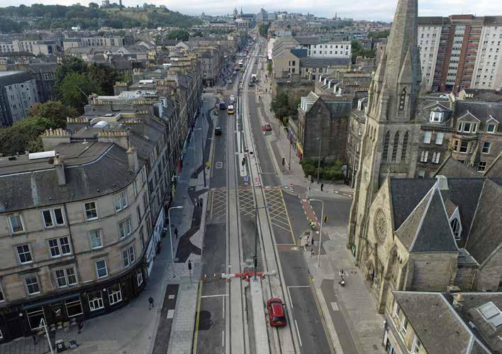
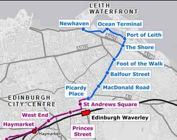
However, it should be noted that the Edinburgh tram project included utility work for the Newhaven section and required much more civil engineering work than the original tram project.

January 2021
Rail Engineer issue 188 (JanFeb 2021) reported on the Newhaven tram project and progress since construction work started in November 2019. Track laying had started in November 2020 and was then in progress along 20% of the route by January.
Excavations, drainage, ducting, and utility work, including the diversion of a 500mm gas main, were also underway although at that time work had yet to start along a third of the route.
Key to the effective delivery of the project were the traffic management arrangements of which the most difficult part was Leith Walk, the busy 1.8km road between Edinburgh and Leith which, during 2021, could only carry one-way traffic. There were four logistics hubs along Leith Walk to provide last mile support for largesized deliveries. This was part of a £2.4 million Support for Business package.
In 2020, Covid-19 stopped work on the project between March and June. An updated programme showed that the tram project would be completed in Spring 2023 within its original £207 million budget.
November 2022
A tour of the project in early November showed good progress with utility diversions having been completed by July and, with two final concrete
(Below) Tracks laid on Leith Walk.
(Inset) Foot of the Walk Logistics Hub.
PHOTO: CITY OF EDINBURGH COUNCIL
69 Rail Engineer | Issue 199 | Nov-Dec 2022 LIGHT RAIL & METRO
pours, track laying completed in October. By the end of that month, five of the eight new tram stops were substantially complete, 136 overhead line poles erected (64% of the total), 8.5km of communications and utility ducting had been installed as well as 4.3km of drainage. In addition, 609 metres of drainage attenuation pipes have been provided to increase capacity and reduce runoff rate.
Two historic objects were returned during the year. As the 1898 statue of Robert Burns needed to be moved two metres east, it had been removed in December 2019. After receiving specialist conservation work it was placed in its new position and unveiled with suitable ceremony on the morning of Burns night (25 January). August saw the return of the 1857 London Road clock which had been restored by a specialist clock maker. This had been absent for 15 years after being removed in 2007 for the original tram project’s utility clearance work.


In early November, surfacing, hard landscaping, and system infrastructure works were evident throughout the route. At York Place, the end of the 2014 tram line, the single line tram stop was removed in February to be replaced by a double track connection to the new tram extension. Trams currently terminate at St Andrews Square and use York Place as a turnback only. When the route to Newhaven opens, the York Place tram stop will be replaced by a new stop at Picardy Place, 80 metres to the east.
Along Leith Walk almost all overhead line poles had been erected with registration arms fitted to those close to York Place. The project has announced that overhead wires will be energised in stages in November and December with the first live section being between York Place and Elm Row (about 700 metres). With much of Leith Walk open to
two-way traffic, there has been a reduction in the number of logistics hubs.
The new tram route will make Leith’s narrow historic Constitution Street open only to trams and pedestrians. During the construction works, footfall has been much reduced, in part due to the impact of Covid-19. One initiative to support businesses during this work is the sale of £5 Itison vouchers which give £10 to spend in Constitution Street businesses.


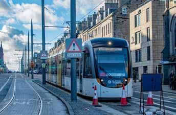
As the South Leith Parish Church graveyard extended across Constitution Street in medieval times, archaeological investigations were an essential part of the route clearance work. This was done by Guard Archaeology in consultation with the city’s archaeologist. As well as the 369 bodies found during the dig in front of the graveyard wall, other finds included whale bones, a cannonball, and a slipway, all of which reveals much of Leith’s long history. With the dig complete, the project is now rebuilding the 90-metre church wall which will incorporate four OLE poles from which tram wire spans will be secured in buildings on the other side of the street.
From the end of Constitution Street, the route runs adjacent to Leith docks and crosses the Water of Leith on the Ocean Drive bridge which had to be strengthened to accommodate the trams. When this bridge was built in the mid-1990s, it closed navigation to Leith’s inner docks. The route then runs past the Ocean Terminal shopping centre where the Royal Yacht Britannia is berthed. The first tram track was laid here in November 2020. Just beyond is Melrose Drive where the last track was installed. From there a ramp raises the formation to its Newhaven terminus. This is the project’s only earthwork. The Newhaven tram stop is substantially complete and has double track extending 60 metres beyond it to provide a stabling facility.
(Above left) Robert Burns Statue returned to Leith. (Above right) London Road Clock.
York Place with tram stop removed, end of the line for now.
70 Rail Engineer | Issue 199 | Nov-Dec 2022 LIGHT RAIL & METRO
(Above) Part of Leith Walk now open to two-way traffic. (Below) Remaining paving works in Leith Walk.
The delayed inquiry
In March 2019, when the City of Edinburgh Council was deciding to authorise the Newhaven tram extension, it was suggested that this decision should await the findings of the Edinburgh Tram public inquiry. It is fortunate that this was not done as this inquiry, which was set up in 2014, has yet to report despite its public hearings being concluded in May 2018. To date, this inquiry has cost £13 million and has taken over eight years. This is two years longer than the Edinburgh tram project.
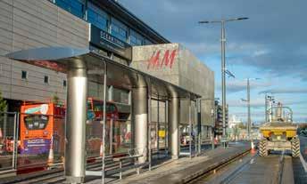
In answer to concerns about the length of the inquiry, a spokesperson advised that: “Lord Hardie’s remit is to conduct a robust inquiry and he has made it clear it will take as long as is necessary to get the answers the public wants in relation to the issues surrounding the Edinburgh Trams project.” Yet surely the public would have wanted these answers before the Newhaven tram project was set up? There is certainly public concern about the length and cost of this inquiry.
Without the need for this inquiry report, the substantive reasons for the original Edinburgh tram project’s problems can be found on the inquiry’s website which has 189 hearing transcripts, 228 witness statements, and 6,428 documents. These were, no doubt, studied by those managing the tram extension project. Lessons certainly seem to have been learned from the original project. The Newhaven tram extension has provided improved business support and community engagement. It also remains on track to finish within its £207 million budget in spring 2023 which, due to Covid-19, is only a few months later than the original completion date.
What next?
When trams start running to Newhaven next year, it will be 24 years since they were first proposed and 10 years since Newhaven might have got its
trams, had the Edinburgh tram project been delivered to plan.
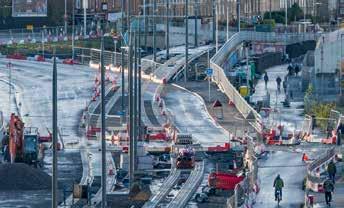
As the new line will serve one of Edinburgh’s most densely populated areas, it will no doubt be well used. It will also provide improved connectivity between the Leith waterfront priority investment zone and the city centre.
In 2020, the City of Edinburgh commissioned a Strategic Sustainable Transport Study to build on the tram’s success and accommodate the city’s growth. Between 2010 and 2020 the city’s population grew by 12.3% which is higher than most UK cities and compares with the Scottish average of 3.8%. The study identified 10 possible tram corridors of which two were prioritised for further development. One is a 6km route to Granton which is mainly along a disused railway that is now a cycle path. This was phase 1b of the 2001 tram proposal. The other is a 12km route to the city’s southeast serving Edinburgh Royal Infirmary. The council plans to complete a final business case for these tram routes in 2025 and aims to have these tram lines completed by 2030.
With the Newhaven tram extension costing £44 million per kilometre, this is a bold vision. Yet the ability of trams to carry, in comfort and with safety, the greatest number of passengers possible in less road space than other forms of transport, offers significant benefits. These are illustrated by UK Tram’s ‘Light Rail Strategy for the UK’ which provides many examples of how trams support economic development and the transition to net zero carbon.
This strategy also shows how Edinburgh’s trams have been instrumental in developers’ investment decisions, enabled various businesses to open new market sectors, and made offices by the tram line more profitable and attractive for staff. With such advantages it is to be hoped that, despite high infrastructure cost and a difficult economic
climate, there will be a strong business case for two new tram routes to Granton and Southeast Edinburgh.

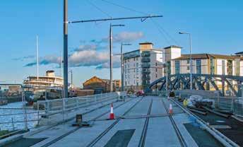
(Above left) Church wall work in Constitution Street. (Above right) The Shore tram stop at the end of Constitution St.

(Above) Ocean Drive bridge. (Below) Ocean Terminal tram stop.
(Below) View from Ocean terminal showing newly laid track, and ramp to Newhaven tram stop which can be seen on the top right of the photograph.
71 Rail Engineer | Issue 199 | Nov-Dec 2022 LIGHT RAIL & METRO
(Below) Work in progress, new LED lighting in situ. No longer concealed lighting over seats.
(Inset) 1992 Tube Stock interior 2022 showing original lighting.
The demand for train services in London is large, growing, and is expected to continue to do so despite the hiatus caused by Covid-19. This trend has been apparent since the early 1980s. London Underground (LU) has been running more and more services for over 30 years and has been upgrading its lines’ capability as trains and signalling become due for renewal. The Central line (see Panel) was the first such integrated upgrade with the 1992 tube stock trains introduced from 1993 and ATO in 2000/2001.
The trains are now nearly 30 years old and are doing far more work than was ever planned, some 160,000 km per train, per year compared with the designed 127,000 km. This article will describe how London Underground is dealing with train reliability and obsolescence issues for the next 10 years or so.


Background

During the early 1980’s LU started to introduce electronics on its trains and there was also great interest in further reducing train weight. 1973 tube stock (Piccadilly line), D stock (District line), and 1983 tube stock (Jubilee line) were fitted with electronic equipment monitoring systems, and LU had pioneered
the use of aluminium in the construction of its trains. Tube trains had retained the steel underframe, but LU wanted to take advantage of the strength and light weight of monocoque aluminium structures using large aluminium extrusions. In addition, GTO thyristor ‘chopper’ control and electronic control systems were becoming readily available.
Chopper control allowed much higher performance in the open sections of the line whilst enabling lower speed in tunnels without the waste of energy that would have been involved if resistance controllers had been retained, as there were no resistors needed in the motor circuits for lower tunnel speeds. This and ATO delivered a muchimproved service frequency with reduced journey times. 85 trains were required, only about five more than the old fleet size. All these concepts were tried out on the 1986 tube stock prototypes prior to the 1992 tube stock being ordered from British Rail Engineering Ltd in 1989. 1992 tube stock is made up of four, two-car units with all axles motored. They have a lot of electronics and are the lightest passenger cars on the LU network.
Most of the electronic components specified were new and had never been fitted to trains before. They included components that could
 MALCOLM DOBELL
72 Rail Engineer | Issue 199 | Nov-Dec 2022 LIGHT RAIL & METRO
PHOTO: BRIAN HARDY
London Underground’s UPGRADING CENTRAL LINE TUBE STOCK
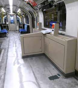
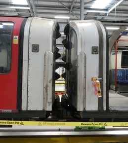
reasonably be expected to be obsolete long before the end of the nominal 40-year life of the mechanical parts. No one knew what the life of the electronics might be, but the best advice was ‘about 20 years’.
In service, the 1992 tube stock has been more troublesome than had been hoped and has required significant unexpected expenditure to keep it going, including the replacement of the bogie frames due to premature cracking. The traction motors themselves have a very hard life with frequent motoring and braking and need a lot of maintenance – much more than forecast. Given that there are 32 motors on every train, this has been a significant burden. There have also been some body cracks. The electronics have been reasonably trouble free but, over time, some of the individual components and, indeed, solder and printed circuit cards have started to fail. Something had to be done, leading to a programme of
works known as the Central Line Improvement Project (CLIP), valued at approximately £500 million.
As well as dealing with reliability and obsolescence issues, the programme also includes provision of features to comply with the Rail Vehicle Accessibility Regulations, age related body repairs, and some heavy maintenance activities. Apart from RVAR legal compliance, the project is expected to deliver reduced maintenance cost, a significant increase in reliability and, as a bonus, there is also an expected 120 second reduction in journey time from end to end. Rail Engineer visited London Underground’s Acton Works in November 2022 to see the work in progress.
The scope includes:
» Replacement of the DC chopper system and DC motors with a modern three phase AC traction package. This involves replacing 2,720 traction motors, fitting 680
variable voltage variable frequency inverters, and replacing 340 auxiliary converters. Supplier: Alstom Sweden, motors from ABB Sweden.
» Replacement of the Train Management System (known as DTS) that will help support the passenger information system capturing more data from upgraded systems with automatic download via 4G and station Wi-Fi. Supplier: EKE-Electronics, Finland.
» Upgrade of the passenger information system with in-saloon displays. Supplier: EKE-Electronics/FOCON.
» Install saloon security CCTV using two cameras per car.
» LED lamps requiring less power (to enable PIS and CCTV) and delivering better illumination. Supplier: LPA, UK.
» Modification to provide compliance with the Rail Vehicle Accessibility Regulations 2010, including spaces for wheelchairs to a design by LU.
(Left) Modification to provide compliance with the Rail Vehicle Accessibility Regulations 2010, including spaces for wheelchairs to a design by LU.
(Right) New (left) and original body ends.
73 Rail Engineer | Issue 199 | Nov-Dec 2022 LIGHT RAIL & METRO
» Repairing door pillar cracks and floor corrosion on all cars; typically 80-90 welds per two car unit.
» Completing replacement of body ends originally started in 2012.
» Door overhaul (8160 pneumatic door engines and doors).
» Bogie overhaul (1340 bogies).
The first trains are currently being modified. The first is due in service in March 2023
and the programme is due for completion in 2027. Observant readers will see that this date is well beyond the 2020 deadline for RVAR works; LU has obtained a dispensation from the DfT.
Planning and programme
Talking to Project Manager Sam McDonough it was clear that this extensive programme would have been even more complicated had trains been sent to established major modification centres around the
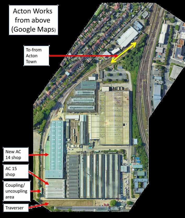
country as moving tube trains over the main line network is far from trivial. In the end, LU decided to do the work in house and in its plans, LU also anticipated the need to overhaul the large sub-surface S stock fleet and forthcoming Piccadilly line 2024 tube stock both of which are not easy to separate into individual cars.
To satisfy this long-term need, a new 170-metre-long workshop known as AC14 has been constructed on former sidings at Acton Works. This provides four 150-metre-long pitted roads, (two of which are each equipped with 32 Mechan lifting stations enabling simultaneous lifting of an 8-car train or individual units/cars), as well as a great deal of storage and office space. For CLIP, AC14 is used for ‘clean’ work, and the adjacent shop AC15 (formerly known as ‘Heavy Repair’) for ‘dirty’ work.
Sam outlined progress since the project procurement kicked off in 2018 and physical work in 2019. Train 1 was the prototype for the AC traction conversion. This work was carried out by Bombardier (prior to Alstom’s take over) in Derby with testing at RIDC Melton. Train 2 was used to develop the saloon electronic equipment installation and Train 3 is the first train with all the modifications. Train 4 will
74 Rail Engineer | Issue 199 | Nov-Dec 2022 LIGHT RAIL & METRO
be the first to include bogie overhaul.
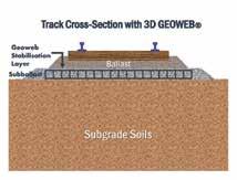
When the programme is up to speed, there will be five trains out of service and each will take 10 weeks/50 days to complete, with one train out of service/ back into service every 10 days.
To deliver the five-train float, the service requirement was reduced by two trains and the remaining three came from the maintenance float. Sam said that, with declining reliability, fleet availability was “tight”.

Each train goes though these stages:
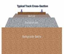
» Ruislip depot: Train fitted with tripcock and driven via the Metropolitan and Piccadilly lines to Acton.
» Acton Works AC15: Train split into individual cars and moved via traverser to AC15. Doors and door engines are removed for overhaul; DC chopper and other redundant material removed for scrap; seats removed; floor coverings and door pillar
covers removed to allow inspection and rectification of cracks/corrosion; fittings removed from centre of cars 2 and 7 to allow fitting of RVAR wheelchair bays; body ends replaced where required; new brackets fitted; and all drilling carried out.

» Acton Works AC14: Cars coupled into units. Doors and door engines refitted;
extensive new wiring installed; brackets to support new saloon displays and window masks fitted; new lights, CCTV, and TDS fitted; traction equipment, brake resistor, and static converter fitted; cars lowered onto bogies fitted with new traction motors; recovered seats fitted; static testing.
» Acton Works: Train tested on
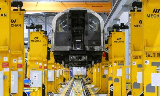
75 Rail Engineer | Issue 199 | Nov-Dec 2022 LIGHT RAIL & METRO
Vehicle on Mechan lifting jacks.
Bogie location on undergframe. New 3 phase traction motor cables in foreground.
short test track; driven back to Ruislip depot.
» Ruislip depot: Tripcocks removed; ATO/ATP recommissioning; authorised to enter service.
Examining trains 1, 2, and 3 in the workshop, it was clear that accommodating all the required equipment in the small space of a tube train is a major challenge with the CLIP requiring more equipment and cabling, not less. Engineers described some of the clever repurposing of existing cables to suit the new LED lighting but, in general, space had to be found for more cables, often in the ceilings where space is severely constrained. There are six seat bays on each car, each of which accommodates two door engines, a heating and ventilation system with much corrugated ducting as well as a variety of equipment.
As Emma Costerton, CLIP’s Electrical Engineer, said: “Every seat bay became a mini project to determine equipment layout and wiring.” Given the number of different car types, that’s approximately 20 different seat bays and in each one the new equipment had to be located and additional wiring provided,
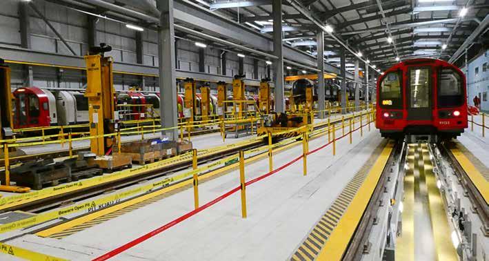
whilst still allowing space for access to and replacement of door engines.
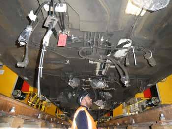
With the new lighting, new flooring and new seats, the trains are starting to look good again and Sam advised that some 'vinyl; film decoration will be carried out. He added that some 100 people are currently employed on CLIP physical works and this number will ramp up to about 180 when the project is completely up to speed.
What next?
The remaining life of the 1992 tube stock is still a live issue. It was bought with a nominal life of 40 years which, based on entry into service, suggests nominal life expiry between 2033-35. But the nominal life
of the existing Bakerloo and Piccadilly line trains was circa 36 years, and they are already well into their 40s. When the contract with Siemens for new Piccadilly line trains was announced reference was made to options for Central line (and Bakerloo line) trains. But since then, TfL’s financial situation, particularly following Covid, has changed significantly. It is possible therefore that 1992 tube stock will have to soldier on, with further engineering interventions from time to time as other parts become obsolete.
Thanks are due to Sam McDonough and the CLIP engineering team for their help in preparing this article.
76 Rail Engineer | Issue 199 | Nov-Dec 2022 LIGHT RAIL & METRO
Interior of AC14 shop.
Central line
The Central London Railway opened in 1900 as the third of London’s tube gauge railways. It originally ran from Shepherd’s Bush to Bank and, with gradual extensions, it eventually reached Ongar (cut back to Epping in 1994) and Hainault in the east and Ealing Broadway and West Ruislip in the west. The line serves 49 stations and is approximately 74km long.
It was originally built with a smaller than standard tunnel diameter, centre third rail, and locomotive hauled trains. It has undergone many transformations and changes of rolling stock over the years, such that it can now be served by standard sized tube trains but with high lift shoe gear. It does have two significant constraints in the form of the most severely curved platform at Bank and also a very small-radius curve between Shepherd’s Bush and White City.

Its designers provided one of the first energy saving features in the form of hump profiles. The track descends on the way out of stations and rises on the approach thus using gravity to help accelerate and brake the trains. This feature proved to be a constraint when the platforms were extended in the 1930s and visitors to central London platforms can observe that platform ends are sometimes on a gradient.
Pre-Covid, it was the busiest line on the Underground
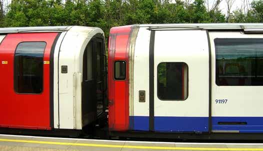
carrying over 250 million journeys annually. It serves four of the 10 busiest stations and also serves five of the 10 least busy stations on the entire network. Passenger numbers are expected to grow significantly before the line is next due for upgrade, despite what is believed to be temporary relief brought by the Elizabeth line.
The current peak service frequency is between 27 trains per hour (tph) and 30 tph. Off peak the service is 24tph.
PHOTO: BRIAN HARDY
77 Rail Engineer | Issue 199 | Nov-Dec 2022 LIGHT RAIL & METRO
PHOTO: BRIAN HARDY
MALCOLM DOBELL

Heritage Rail Association: SAFETY, SUSTAINABILITY, AND GOVERNANCE
Heritage Railway Association Autumn Conference.
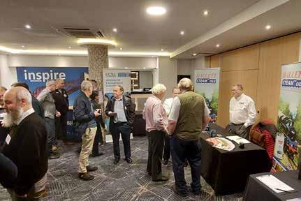
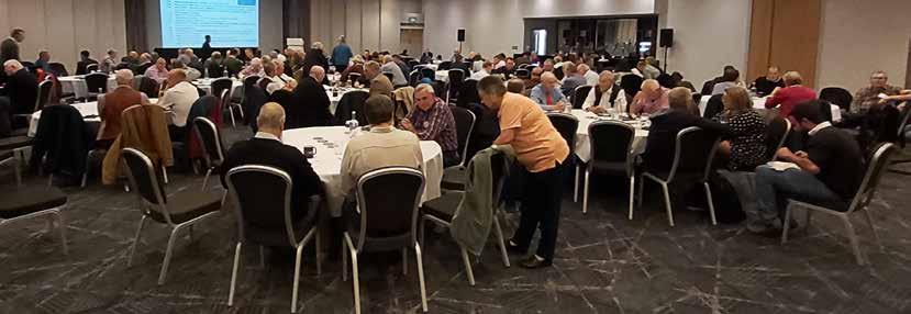
In Issue 168 (October 2018) Rail Engineer published a heritage rail article titled ‘20th Century Heritage, 21st Century Safety’. Since then, Covid, 2022’s extremely hot summer, inflation, and staff/volunteer shortage have all meant significant challenges for heritage rail. It was with great interest, then, that we visited day one of the Heritage Rail Association’s (HRA) Autumn Conference in Birmingham in November 2022. The main themes for the day were safety, sustainability, and governance. Here are the highlights.
HRA’s chief executive, Stephen Oates, welcomed a very healthy turnout (nearly 200 people over two days) and outlined the challenges ahead based on a recent business confidence poll of his members. Generalisation is risky, but just under half of the respondents had a worse 2022 than 2021 with operating surpluses reducing, unpredictable demand, and with a significant minority seeing customers spend less.
20th Century assets, 21st Century safety

Andy Castledine, an independent railway consultant, and Operations and Safety Director of West Somerset Railway (WSR), set the scene. He outlined WSR’s journey after a troubled time pre-Covid. When he arrived, Andy said he found that WSR had a good rule book but that there were gaps in systems and processes which meant that “they couldn’t prove that the
rule book was being complied with”. After several visits from the ORR, work to create a robust safety management system was implemented with a large action tracker sheet and keeping the ORR informed of progress.
Andy turned to the big picture. Most of the heritage sector works with obsolete assets, using old skills deployed by a largely volunteer workforce. This leads to a high risk profile that involves risks not seen on the main line railway. He presented some worrying statistics. For example, whether measured by mileage or passenger journeys, the heritage sector represents a tiny proportion of the national network but received a third of all ORR enforcement action.
Heritage Railway Association Autumn Conference exhibition area.
Some operators were struggling to attract sufficient volunteers, not necessarily caused by fewer new volunteers, but often because existing volunteers cannot work as many days due to pressures such as fuel costs for journeys to and from the railway. Most operators think their activities for the end of 2022 will see the same or higher numbers than in 2021. Looking ahead, most were expecting to open for the same of more days next year, but in terms of business confidence nearly 80% were unsure or not confident.
FEATURE 78 Rail Engineer | Issue 199 | Nov-Dec 2022
Andy wondered: “Why are these factors so prevalent and do our systems, processes, and competence management systems recognise the fallibility of people?”
He added: “…are our medical standards adequate? Are our assessments adequate? Do we assess cognitive performance as it declines with age? Do we have adequate occupational health provision?”
Addressing all these factors will have a cost but Andy stressed that failure to do so would cost a lot more.
This has led HRA to conclude that something must be done and it is seeking to set up a Heritage Rail Safety and Standards Board (HRSSB). Andy said that discussions are taking place about whether the DfT or the Department of Culture, Media, and Sport should take the lead in funding HRSSB. He added that, as a fallback, the current HRA Operations and Safety Committee (which he chairs) might be expanded to produce more safety standards and additional technical advisory documents.
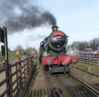
An inspector calls
Three representatives from ORR spoke. HM Deputy Chief Inspector for Railway Safety Richard Hines set the scene, echoing the Chief Inspector’s remarks in the 2021-22 Annual Report of Health and Safety on Britain’s Railways: “… Whilst it was reassuring that
our inspections continued to find that individual railways were making progress to address gaps in their safety management systems, we did identify some significant shortcomings through our inspection and investigation work…”.
Richard said that his team recognised their role in keeping heritage alive for future generations, but he reiterated Andy Castledine’s point that 21st century levels of safety were required despite using old assets, adding that in current economic conditions some hard decisions might be required, e.g., if considering deferring maintenance, the risks of so doing must be properly evaluated. Richard also emphasised the importance of skills and knowledge in governance rather than ‘time served’, before adding that ORR supports the creation of HRSSB and is actively helping to secure funding.
Reflecting on the last year, Patrick Talbot, HM Assistant Chief Inspector of Railways and head of the non-main line team, said that the ORR’s Risk Management Maturity model shows the heritage sector in general is working between ‘adhoc’ and ‘managed’ – the lower levels of the maturity model. Two enforcement notices had been issued, there had been a number of operational incidents (two of them serious), asset management of both trains and infrastructure is an issue, and competence management is an underlying factor in many incidents. He illustrated the condition of cast iron columns, uncontrolled movement of rail vehicles and working at height as current concerns.
Investigation
Alongside a representative of the railway concerned, Simon Barber, HM Principal Inspector of Railways, presented a case study of the investigation following a collision. A locomotive was being driven into a platform to couple to a train where passengers were boarding. It was driven by someone not yet passed out to drive that loco, under the supervision of a traction inspector.
The driver misjudged the distance and collided with the train at low speed causing minor injuries to a small number of the 175 people on board the train. ORR undertook a site visit, held discussions with staff and reviewed records, CCTV,
 Ex Southern Railway West Country ‘Taw Valley’ Severn Valley Railway 2018.
FEATURE 79 Rail Engineer | Issue 199 | Nov-Dec 2022
Great Central Railway Visitor train for Repoint demonstration 2019
Bure Valley Railway testing ‘Ecocoal’ 2021.
photographs, and the railway’s safety management system/ supporting documentation.
The inspector found that the railway could not demonstrate the competence of the traction inspector and an Improvement Notice was issued. The railway’s representative had quickly identified that the root cause was human error. As the ORR investigated, the railway thought that its computerised operations management system would demonstrate appropriate competence but found that the computer system had been relied on too much without auditing the paperwork inputs.
It was after this discovery, and following a round table discussion between the railway’s management and the ORR inspector, that the Improvement Notice was issued, something that the railway felt amounted to a joint decision. An external consultant helped them to improve the competence management system and the Improvement Notice was closed on time.
people will not work. The wrong structure with the right people will only keep going as long as all these people continue to work well together, and nothing goes wrong.
Nick outlined five structures that could be used, noting that the first two and the last are most frequently used:
» Company Limited by Shares (CLS): Shareholders own the company; profits can be withdrawn as dividends; cannot be charitable; hard to raise money from the public.
» Company Limited by Guarantee (CLG): No shareholders, members instead; cannot easily withdraw profits; can be charitable; can raise funds from donations and debt.
» Charitable Incorporated Organisation (CIO): A bit like a charitable CLG registered solely though the Charity Commission.
» Community Benefit Society (CBS): A bit like a CLG but regulated by the Financial Conduct Authority (FCA); must be set up based on model rules from a ‘sponsor’ and must be ‘for the benefit of the community’.
» Unincorporated Association (UA): very flexible but no limited liability.
Nick highlighted that typically, heritage organisations might set themselves up as CLGs at the top level but set up one or more subsidiary CLS companies to allow the CLG to receive profits from trading.
He also reminded everyone about the duties of directors. They must: act within their powers; promote the success of the company; exercise independent judgement; exercise reasonable care, skill and diligence; avoid (preferred) or declare conflicts of interest (for example, someone might sit on the heritage railway board and on the board of a company that owns rolling stock that runs on the railway); and not accept benefits from third parties.
Asset management
Heritage railways have to manage old assets. Compared with what is typical on Network Rail, they are often able to take line closures to enable inspection to be carried out during daylight. Heritage railways also represent ‘safe spaces’ for organisations to test new techniques. David Gent from ECSL, a bridge inspection specialist, outlined some of the techniques his company uses for clients including about a dozen heritage railways.
He described a number of constraints that create inspection and assessment challenges for heritage railways including: limited access to expertise to understand structures/ materials; being tied to standards which are geared towards modern structures/ materials; together with financial, site, programme, and access constraints. Tools and techniques include laser
London Transport Pannier Tank L92. Epping Ongar Railway 2021.
Governance duties and structures
Returning to governance, Nick Dunn from Wrigleys Solicitors outlined the importance of setting up and maintaining the right structures to ensure that railways can deliver their objectives. Whilst having an appropriate structure is important, it is also vital to have the right people round the boardroom table. The right structure with the wrong
FEATURE 80 Rail Engineer | Issue 199 | Nov-Dec 2022
and drone surveys, with many of ECSL’s surveyors qualified as drone pilots. David showed an example where a turntable whose operation was stiff was found to have a very small deviation on its track which was revealed in a laser survey.
Timothy Pennock from Collins Aerospace discussed how airborne reconnaissance systems might be adapted for railway applications. Cutting a long and complicated story short, the principle is that sensors are used to create repeatable 3D images that can be overlaid and analysed for variations. Tim demonstrated how spalling of bricks forming a tunnel might be determined from this data acquisition and analysis, a process requiring far less access than would be necessary if carried out manually. He proposed how this process might be extended to the permanent way giving information about the track itself and the general area between boundaries.
Carbon neutral?
Ian Purkis, who volunteers with the Keighley and Worth Valley Railway and Paul Vidler, a volunteer for the Kent and East Sussex Railway, delivered a presentation titled ‘What Does a Carbon Neutral or Environmentally Responsible Railway Look Like?’. They said: “Heritage Rail may only burn a tiny fraction of the coal burnt in UK (e.g., steel, cement) but that doesn’t make it any easier
or even possible to be carbon neutral. The same applies to diesel fuel, again a tiny fraction of total UK use.”
Their interpretation was that carbon emitted should be equal to or less than the amount absorbed or stored.
But it’s not just about coal and diesel, they mused:
» Carbon - is it just carbon or does it include other emissions such as methane?
» Does the change in carbon storage capacity of land that you control (trees, soils etc.) count?
» What about emissions from indirect use e.g., electricity and emissions from things you have bought?
» Are you responsible for emissions by your visitors, staff, and volunteers travelling to/from site?
» How far ahead do you look?
Is it a plan for 50 years? (20 years or less won’t include full benefits from growing trees, for example).
They showed figures to demonstrate that planting a tree to offset CO2 from coal requires an unsustainably large number of saplings. They were forced to conclude that it is unlikely that a carbon neutral heritage railway can exist, but that decarbonising in every possible way is good for the environment and as a way of engaging with visitors and stakeholders. This must start from the top with board and management commitment and strategy for sustainability and protection of the environment (there is HRA guidance). They should communicate though the railway’s website, briefings, presentations, and newsletters to demonstrate that the environment and sustainability is embedded within all aspects and all levels of the business.
Further green concerns Clearly, extending the life of vehicles, equipment, materials, and buildings that would otherwise go to scrap is a key sustainable activity. Generally, heritage railways have been recycling scrap metal for many years.
Ex BR 9F class ‘City of Leicester’ at Leicester North, Great Central Railway October 2021.
Great Central Railway. 2nd World War event 2021 “Up Yours Adolf”.

FEATURE 81 Rail Engineer | Issue 199 | Nov-Dec 2022
Romney Hythe and Dymchurch Railway 2014. Loco Hurricane at Dungerness.
Numerous examples were presented demonstrating care for the environment whilst making the railway more attractive such as station gardens with bee-friendly plants, bird boxes, bug hotels, and more extensive work such as lineside habitat conservation. And then helping educate visitors about what has been done including leaflets, children’s activity sheets and on-train guides.
As a final point they expressed the view that heritage railways really must end the practice of discharging toilet waste from passenger coaches onto the track, something that must end on heritage vehicles on the main line by 2023.
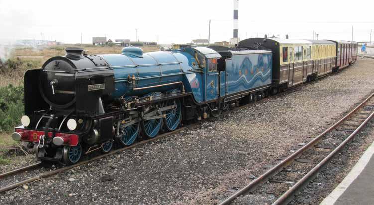
This was a very wide-ranging event including a second day about more commercial matters which Rail Engineer did not attend.
With thanks to the Heritage Railway Association’s Mark Pearce and Amy Sugrue for their help.
The ORR’s Risk Management Maturity model can be found at: www.orr.gov.uk/sites/default/files/2021-03/rm3-for-heritage-sector.pdf
HERITAGE RAILWAY ASSOCIATION
There’s more to heritage rail than just the trains. It’s a sector that has grown continuously since the 1950s and generates enormous benefits for communities throughout the UK.
The UK heritage rail sector is an important component of the tourism industry, generating value to the UK visitor economy. It is a key element of many tourists’ holidays. The sector protects, conserves, and brings to life part of the nation’s cultural heritage, and helps to promote the UK around the world.
Heritage rail provides social, community, and wellbeing benefits to employees, volunteers, and visitors throughout the UK.
The Heritage Railway Association represents: » 173 working railways » Nine operational tramways » Eight cliff railways » 24 museums and steam centres many of which operate trains on selected days
17 commercial partners » 100 societies, funding groups, and locomotive and carriage owning trusts » 22,000 volunteers » 4,000 paid employees
Its members own or operate: » 560 miles of track » 460 stations » 800 steam locomotives » 1,000 diesel locomotives » 2,000 carriages » 4,000 wagons
Its impact on the UK economy: » 4,000 employees » £400 million economic value » 13 million visitors who take 18.6 million passenger journeys covering 130 million passenger miles.
»
FEATURE 82 Rail Engineer | Issue 199 | Nov-Dec 2022

way People.com
the
of
RailwayPeople.com is the largest dedicated rail job site in the UK. With thousands of job opportunities updated daily, your next career is a fingertip away. Visit RailwayPeople.com to find your next role today. Tel: +44 (0)1530 816 450 @railwaypeople CAREERS 83 Rail Engineer | Issue 199 | Nov-Dec 2022
At
heart
UK rail…
What is RailwayPeople.com?


RailwayPeople.com is the largest dedicated rail job board in the UK.


How can it help me?
With the top career opportunities updated daily, your next move is a fingertip away.


What


role! way People visit: www.RailwayPeople.com / email: rp@rail-media.com / telephone: 01530 816 450
should I do? Visit RailwayPeople.com to find your next role and become an essential part of the UK’s rail industry to help the nation build back better. With roles updated daily, don’t delay – visit the website, today. Find your
Together
Signalling a career in Western Australia


Signaller / Network Controller Career Opportunities


About Arc Infrastructure
Arc Infrastructure manages and develops transport infrastructure assets that support growth and create jobs in Western Australia (WA). Rail is at the heart of our business, and the 5,500km rail network is the backbone of freight transport in Western Australia. Spanning a region around the same area as continental Europe, from the Midwest across to the Goldfields, and through to the stunning South West and Great Southern.We’re committed to working with industry, our customers, partners and communities to find new opportunities that will support and strengthen our rail network for the benefit of WA.
The Opportunity

Arc Infrastructure’s network control team is critical to our business, and responsible for the safe, economical, and effective monitoring and control of train services across our entire rail network.
We currently have opportunities for experienced Signallers / Network Controllers to join our team and make a difference on our network.
About you


The successful applicant will be an experienced Signaller/Network Controller who remains calm under pressure, is motivated, and is an excellent communicator.

You will be provided with in-house theoretical and on the job training. From our Perth-based network control centres, our experienced network controllers will work with you to help you adapt your skills and experience to our network. You will be working 12-hour shifts on a rolling roster over an average 38 hour working week.
Careers at Arc Infrastructure


Arc Infrastructure has created a culture of team work where diverse skills, ideas, and experience are valued. We promote a work environment that is characterised by personal accountability, mutual trust, and respect. At Arc, we take a genuine interest in our employees and their development. We understand our employees are the key to our success and, as a team, our focus is to ensure they feel safe, valued and fulfilled in the work that they do.
We will provide the successful applicant with a competitive remuneration package starting at $99,000 base salary, plus annual shift allowance of $27,663, plus employer superannuation contributions of 10.5%. In addition, we offer a benefits package including Visa sponsorship and relocation assistance.

ARC’S RECRUITMENT PROCESS

Arc Infrastructure will be in the UK as part of our recruitment drive in early 2023, please scan the QR code to apply.


www.arcinfra.com

WE GO BEYOND


…This Christma s we’vegotyou thejobyou’ v e always wanted…
…with the largest dedicated website for rail opportunities, we’re sure to have the career for you
VISIT WWW.RAILWAYPEOPLE.COM TODAY Railway People wishes you a very Merry Christmas and a Happy New Career.
We are constantly
for new talent to strengthen the Colas Rail UK team.
Our people are our strength, and everyone working for Colas Rail UK plays a vital part in the company’s success.
Joining Colas Rail UK provides the opportunity to not only establish yourself within one of the biggest contractors in the rail industry, but also the springboard to take your career to new heights.
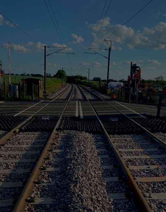
We’re always looking for passionate people to join our business and with several bases across the UK, there are plenty of opportunities to join our Railway family.
We offer an attractive salary and benefits with a culture of can do, empowerment and flexibility, to allow you to make a real difference.
We would like to hear from people who would like to work in the rail industry.
Please register your interest by sending your CV to recruitment@colasrail.com and we will provide you with further information.
www.colasrail.co.uk » Production Manager » Site Supervisor » Site Engineer » Project Lead » Site Manager » Project Lead » Technical Engineer » Apprentice P-Way » Development Manager » Pway Supervisor » Development Manager DRIVEN BY CHANGE Join Our Anglia Rail Team Career Opportunities Include: CARE | SHARE | DARE
looking

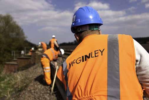
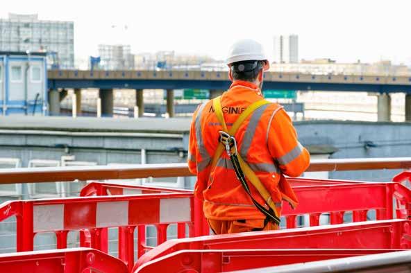

People for Infrastructure Call now 0845 543 5953 info@mcginley.co.uk Scan me to view live roles. McGinley hires workers or finds permanent employees for companies in the infrastructure sector of the construction industry, building and managing workforces all over the UK Whether you are looking for a job or a supply chain partner, we have the knowledge and expertise to help you succeed As true infrastructure experts we have over 40 years ' experience and an unparalleled network. This combined with a large number of accreditations, memberships and awards give you the confidence you need to engage with us. • PTS & safety critical contingent labour • Signalling & telecoms • Overhead line electrification • Track welding • Minor works packages • Flexi-jobs apprenticeships WE ARE RECRUITING


 (Right) The world’s first electric train.


 PHOTO: LNERGRAEME ELGAR


 DAVID SHIRRES


 (Below) QTS Rench Farm facility in 2022.
(Left) Rench Farm’s workshop.


 DAVID SHIRRES


 Kelvin Davies explains the competition.


 Guillaume Chanussot.


 MALCOLM DOBELL


 Ex Southern Railway West Country ‘Taw Valley’ Severn Valley Railway 2018.


