1 minute read
FSS#1
Nexorade
Tehran, Iran | Winter 2019
Advertisement
Role: Manager and Tutor
Credits: Photos and diagrams were created by the workshop students and instructors. https://issuu.com/ramtinhaghnazar/docs/fss1-nexorade-portfolio2
FSS program, Freeform Space Structure, is a part of long term research which leads by me in Digital Craft House. This research tries to study different ways to build a freeform space structure.
In each step, the various researcher focuses on a topic and try to develop it. The result of this development appears in an academic workshop. FSS#1 was an academic workshop that worked on the Nexorade structure based on Olivier Baverel’s research. FSS#1 was a 10 days workshop.
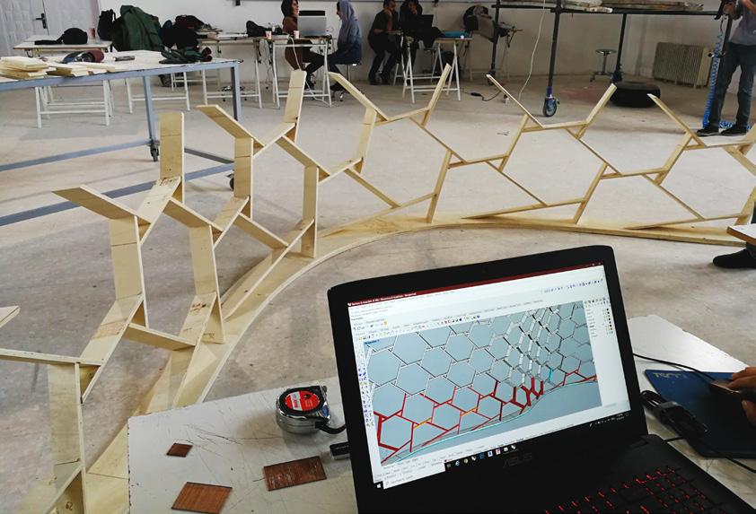
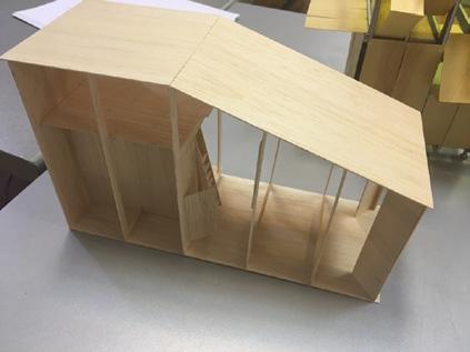
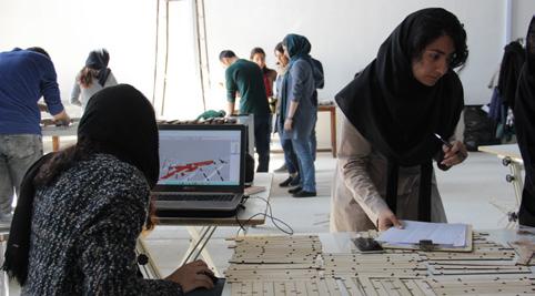
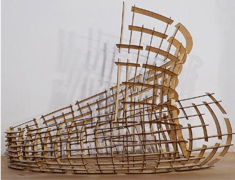
In the second phase, students experienced integrated computational design and fabrication. They tried to design a Nexorade which was able to build using 3mm thick plywood and laser cutting system. They consider a simple joint detail and developed a Grasshopper code to generate model and shop drawing.
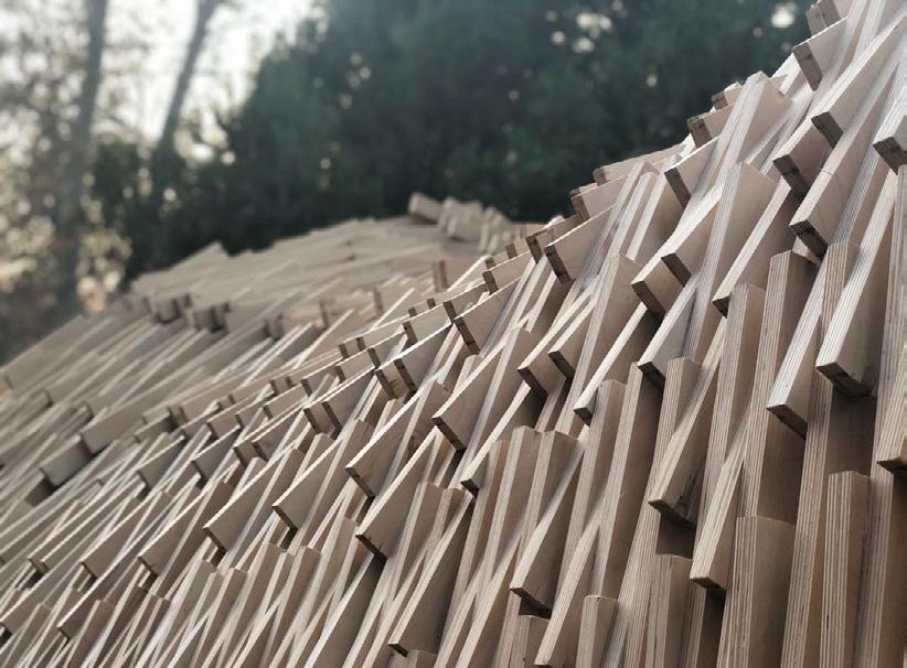
In the beginning, students tried to understand the logic of the Nexorade. Thus, they tried to build a simple structure by overlaying simple wooden sticks.
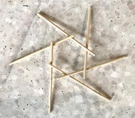
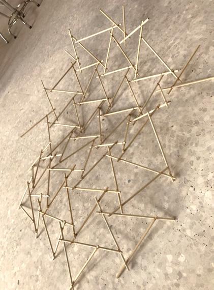
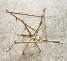
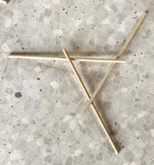
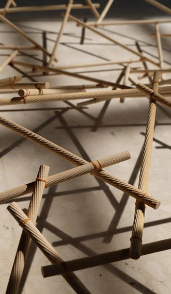

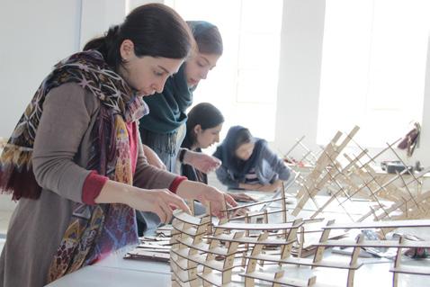
Below: Students’ samples for the first phase.
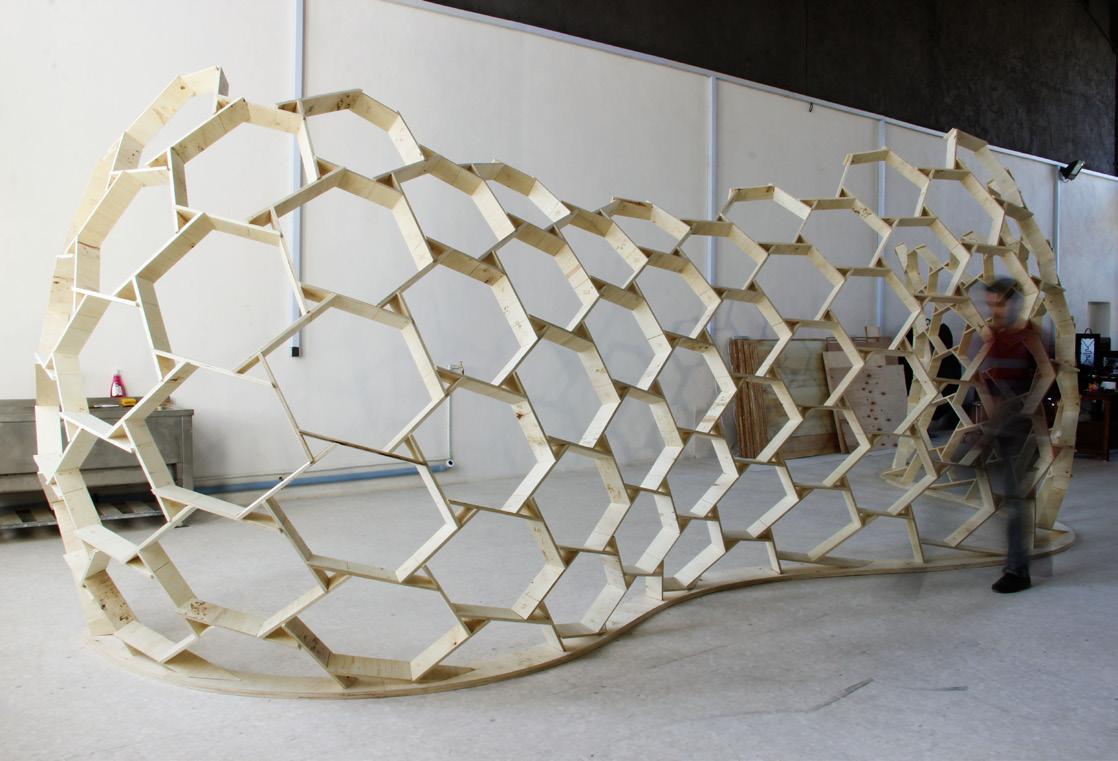
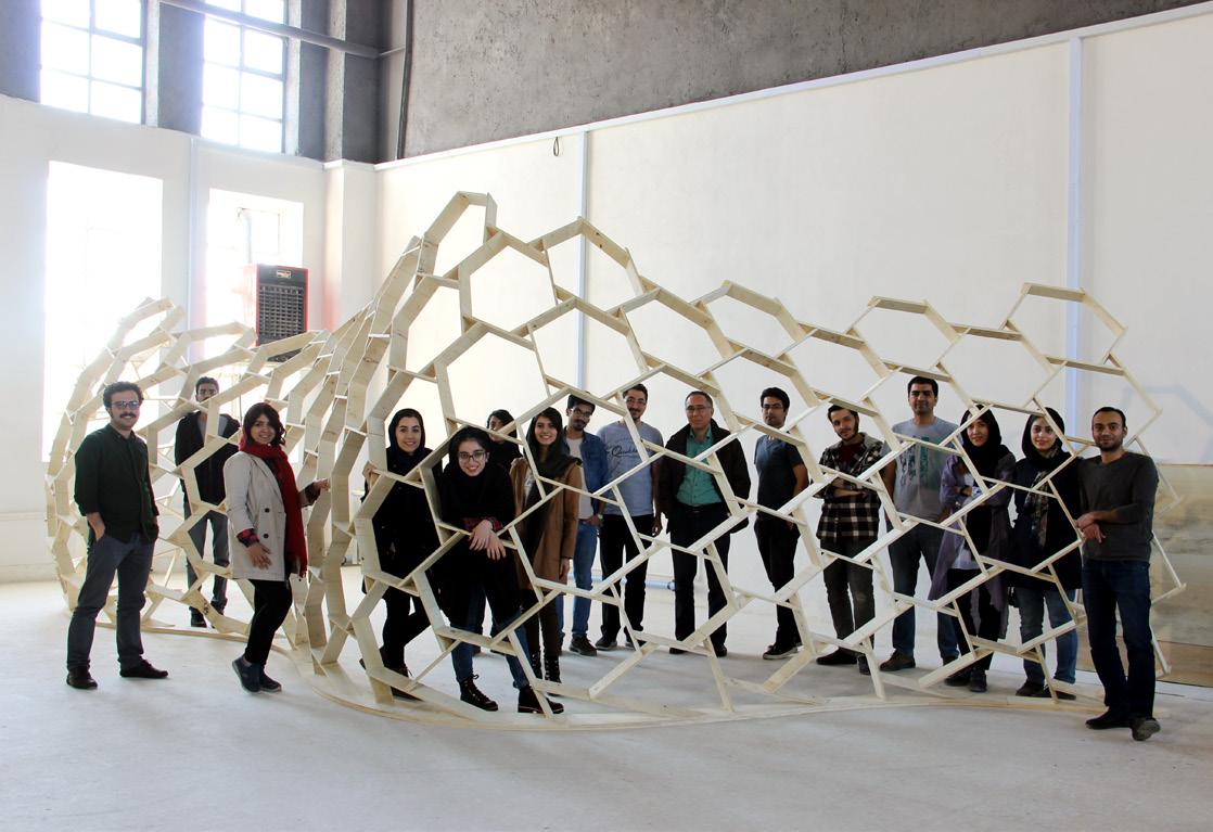
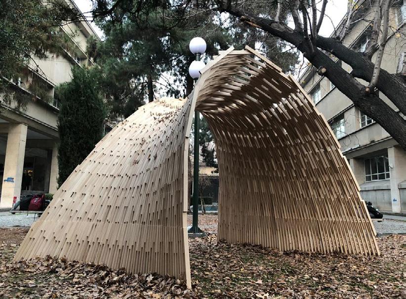
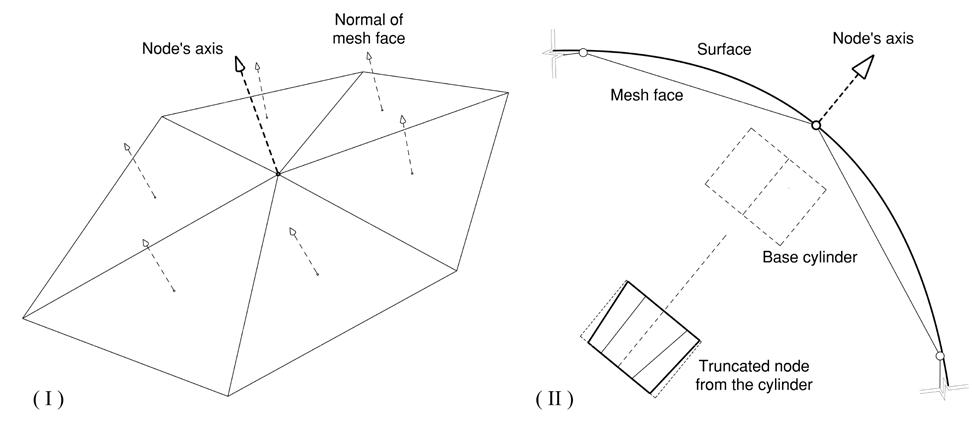
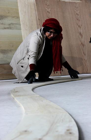
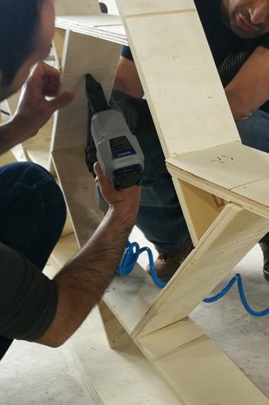
In the final phase, one of the students’ models accepted for the final real scale model. This proposal contained a partition which separated two parts of the DCHouse. Here, students try to find the best detail for the joints considering restrictions; material was restricted to 12mm thick plywood, and technique was limited to CNC milling machine.
Preliminary wire mesh
Extending the elements Rotating the elements
Generating the surface
Three things added the final model:
Footprint of the element
Pattern drawing
A line considered design and carved the CNC to show nailing position
Rotating the elements
Making the elements’ base
Generating the final shape of the elements
Extending the elements
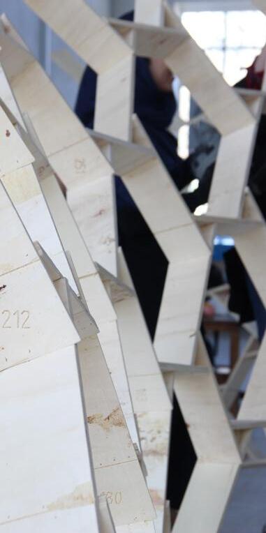
To ease in assembling, footprint of each element engraved on the
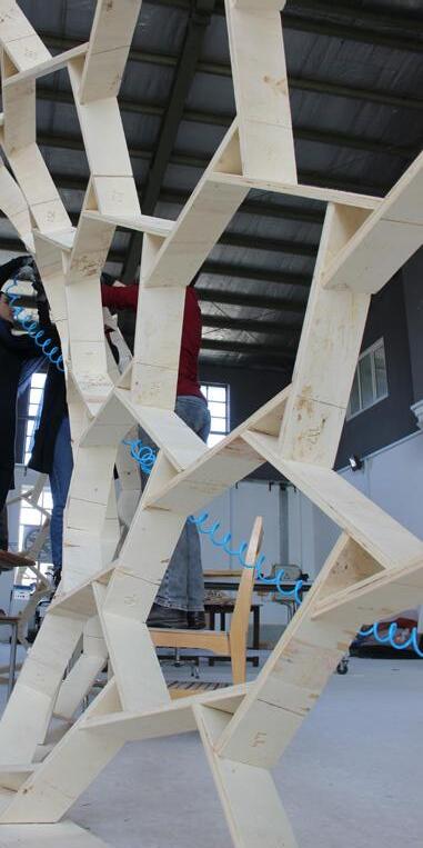
After creating the model as illustrated, the team has tried to make a G-Code for the CNC milling machine to cut the elements in the designed angle. Then, the structure footprint considered as the base plate. Next, students tried to place elements one by one to the end. During this process, a person navigates the others and tells them how to place each element. Installation takes around 15 hours. in the carved bay show the position assembling, element other. added to model: Numbering Nailing line the other element model Fabrication
