32 minute read
Innovative Field Development Solutions: Enabling Technologies for Long Subsea Oil Tiebacks
Alessandro Radicioni, Giorgio Arcangeletti, Annalisa Di Felice, Amerigo D’Amico, Enrico La Sorda, SAIPEM S.p.A.
Introduction
In a market scenario dominated by low oil prices, operators are keen to find new architectural solutions for field development that bring about a reduction in the CAPEX and OPEX. In this context, developing new floating facilities and the related subsea network for a production of around 50kbopd is overly expensive. Today, the preferred solution appears to be a subsea tieback to an existing facility. Traditionally, the industry has developed tiebacks within a range of 10 to 30km.
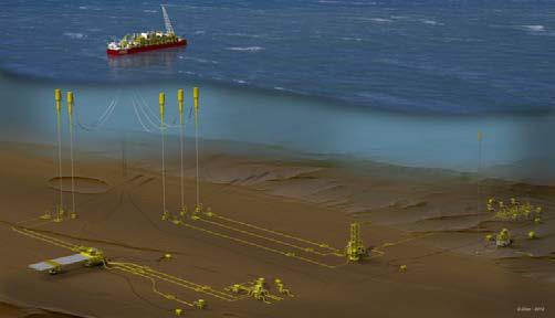
Looking towards the future, the target tieback length could increase to 50km or more (see Fig. 1) but several challenges have to be overcome to make it technically feasible and economically viable, mainly: • flow assurance linked to hydraulic, thermal and operability requirements, especially in transient conditions (see next section). • technologies needed to overcome the flow assurance challenges, especially considering the long distances from the wells to the topside facilities. • the necessary topside equipment integration and/or modifications.
The long distance between the oil production wells and the treatment facilities generally requires the use of subsea pumps that have to be installed in the correct position based on the fluid characteristics and the well flowing conditions along with the chosen transport line diameter. Moreover, wet insulated or PiP and heated lines become necessary.
By increasing the step-out distance, other elements of the traditional architecture may reach their technical and/or economical limits. For example, conventional chemical distribution and subsea facility control using hydraulic systems will have to be rethought, switching to the subsea chemical distribution and all electric concept.
Optimizing the development of these types of tiebacks considering all these challenges is not an easy exercise but it is one that offshore O&G industry players are trying to do.
To offer the best response, considering all the aspects involved such as system design, selection and procurement of the main technologies, fabrication and installation challenges etc., SAIPEM launched an in-house project whose aim was to design, develop and optimize the subsea field scheme. This project is based on SAIPEM’s extensive experience in challenging URF EPCI projects and on technologies that SAIPEM has already developed or is developing. Identification of technology requirements and their relative status along with the potential development plan is an essential part of this initiative. To achieve the project’s aim, several case studies were selected and investigated to define the best development schemes with the aim of identifying and developing technologies to be used as building blocks for long subsea tiebacks and to generalize the results achieved. The goal was to build the main innovative elements of subsea field architecture to propose to Clients in order to fulfill specific project requirements and constraints, and to make the exploitation of new reservoirs profitable, maximizing the use of existing facilities.
Some key or new technologies were identified and included in specific R&D programs aimed at developing proprietary technologies, or at entering into agreements with potential partners (i.e. Siemens for the Control System) in order to gain a commercial advantage in that market segment.
Fig.1 – Example of an ultra-deep water long tieback field architecture
Long subsea oil tieback flow assurance challenges
The transportation of live oil over long distances poses several challenges due to a combination of factors: • the fluid characteristics, such as the intrinsic risk of deposits (asphaltene, scaling, waxes) • the available pressure and temperature downstream of the production chokes to produce reservoir fluid up to the topside • •the low ambient temperature leading to the risk of hydrate formation These criticalities, which are also present in short tiebacks, are managed through a combination of the design of the transport facilities, the injection of chemicals (at the correct point of the subsea systems) and the development of appropriate operating procedures, to keep the operating envelope away from dangerous conditions, above all in transient conditions. The main flow assurance issues are traditionally managed using thermal insulated looped lines (conventional loop with identical production lines or hybrid loop with a dedicated service line) with the aim of delivering production fluid above the wax or hydrate appearance temperature (WAT/HAT). This design minimizes the use of chemicals because of the possibility of displacing live fluid in the case of shut-down and the possibility of pre-heating the flowlines before the field restarts. For pressure management in the transport system, the tools typically used in the scenarios considered are gas lift, either in the subsea wells or at the riser base and the use of production
system based on a preservationsingle heated line, different configurations can be arranged to fulfill prof long subsea flowline from the critical path in oduction requirements and respect brownfield constraintsemergency shut-down for specific field requirements. Since some of proposed technologies require high subsea electrical power, the subsea power distribution system will become a main part of the new developments, to be integrated and optimized in conjunction The heated flowline is the main building block in these types of developments. Other building blocks need to with more conventional systems.be identified to propose solutions that are effective in solving the criticalities of tiebacks to existing facilities and that enable the development of reliable and flexible solutions. Table 1 below sums up the main building blocks to take into consideration and that are applicable to long subsea oil tieback development. Considering that the most promising solution is a transport system based on a single heated line, different configurations can be arranged to fulfill production requirements and respect brownfield constraints for specific field requirements. Since some of the proposed technologies require high subsea electrical power, the subsea power distribution system will become a main part of the new developments, to be integrated and optimized in conjunction with more conventional systems. subsea pumps. Considering that the preservation of additional long tiebacks to existing facilities will be postponed until after the original production loops and that the distance from-to the floater increases, this design and operating philosophy are difficult to apply due to: • CAPEX of double line • time constraints to put the displacement and heating in place • large volume of displacement fluid to be hosted onboard the FPSO For the above reasons, new concepts have been introduced in the development of these fields, specifically, the single heated line. The following operating scenarios can be managed with a heated line:
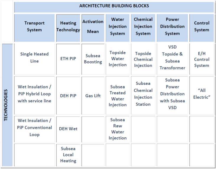
Tab. 1 - LSSTB System main building blocksTab. 1 - LSSTB System main building blocks
Figure 2 below shows an example of a subsea architecture solution for a tieback of • keeping the production flowline transport around kbpd and 50 - 60 km with very limited space on the host facilities. system warm: the heating system is maintained at minimum power to keep the fluid above HAT in the case of short shut-down • •re-heating operation: in the case of a prolonged shut-down, the live fluid cools down to sea bed temperature. When production is ready to be restarted, the heating system is activated to raise the fluid temperature above HAT or WAT • low turn-down/transient management: the heating system can be kept on to enable production at a reduced rate or to Tab. 1 - LSSTB System main building blocksmanage specific transient operations Figure 2 below shows an example of a subsea architecture solution for a tieback of around kbpd and 50 - 60 km with very limited space on the host facilities. Current technologies to heat a subsea pipeline are: 50
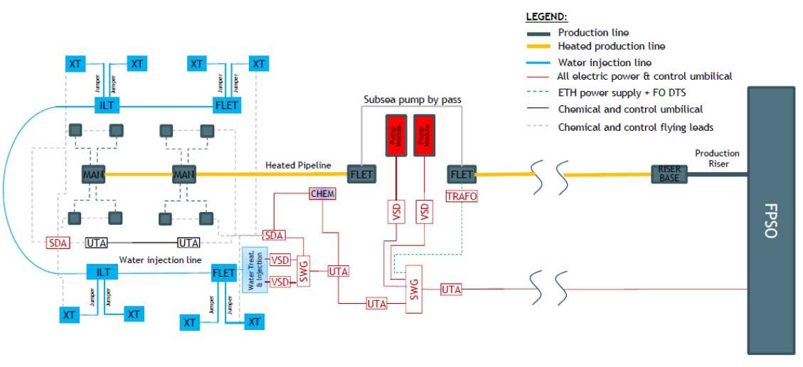
Fig. 2 – Example of a long ultra-deepwater oil tieback field architecture
4
• Direct Electrical Heating (DEH) with wet or pipe-in-pipe insulation • Electrical Tracing Heating (ETH) with pipe-in-pipe
The DEH technology is well-proven with wet insulation even if improvements are ongoing in order to optimize it for more challenging scenarios. SAIPEM has focused on the development of ETH – PiP because it represents the best combination in terms of thermal performance and optimization of power consumption and, hence, a containment of the OPEX.
Long subsea oiltieback architecture selection
As stated above, the key element able to make long subsea tiebacks feasible is the heated pipeline. This technology has several benefits: • it reduces the number of pipelines from-to the FPSO • it reduces the amount of displacement fluids and chemicals that has to be stored onboard the topside facility • it removes the preservation of long subsea flowlines from the critical path n the case of emergency shut-down
The heated flowline is the main building block in these types of developments. Other building blocks need to be identified to propose solutions that are effective in solving the criticalities of tiebacks to existing facilities and that enable the development of reliable and flexible solutions. Table 1 below sums up the main building blocks to take into consideration and that are applicable to long subsea oil tieback development. Considering that the most promising solution is a transport system based on a single heated line, different configurations can be arranged to fulfill production requirements and respect brownfield constraints for specific field requirements. Since some of the proposed technologies require high subsea electrical power, the subsea power distribution system will become a main part of the new developments, to be integrated and optimized in conjunction with more conventional systems
Figure 2 below shows an example of a subsea architecture solution for a tieback of around 50 kbpd and 50 - 60 km with very limited space on the host facilities.
A single heated production line is envisioned. Together with the subsea pumps, the heating system is supplied via a subsea electrical power chain. Seawater treatment and injection and chemical injection could be located subsea allowing significant savings in the number of slots required to tie in the new field and in the
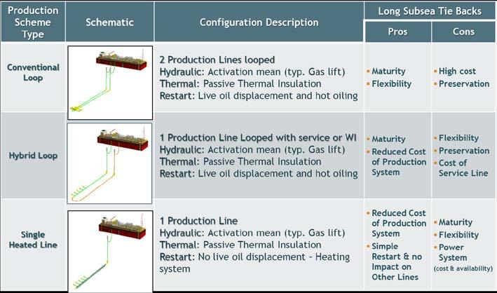
Fig. 3 - Long tieback field architectures options Fig. 3 - Long tieback field architectures optionsFig. 3 - Long tieback field architectures options
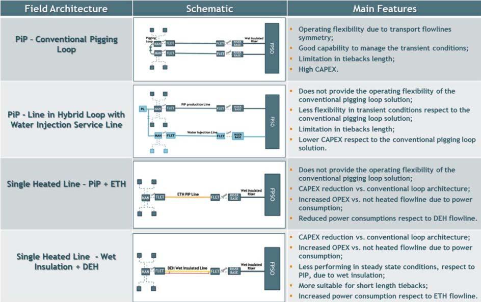
Fig. 4 - Heated pipeline systems options Fig. 4 - Heated pipeline systemsFig. 4 - Heated pipeline systems options options
footprint on the FPSO. This concept, coupled with the all-electric control system, simplifies the main umbilical that could become a power cable. This solution allows a reduction in the investment in power cables, reducing the cross-section diameter and simplifying the power cable packing and installation tasks .
Heated and insulated flowline system
The flowline system is the backbone of a subsea production and transportation system. Its sizing must respect the hydraulic and thermal requirements in all the operating phases envisaged during the life of the field. Figures 3 and 4 below summarize the main architecture and flowline systems potentially applicable in long subsea oil tiebacks. The configuration with heated pipeline is the most promising to manage the shut-down and restart phases from the point of view of both cost and flexibility. The need to develop a SAIPEM ETH PiP emerged during the numerous field architecture studies, showing the advantages of this highly efficient heating solution in long subsea tiebacks and the need for an ETH PiP suitable for very to ultra-deepwater.
The SAIPEM Electrically Trace-Heated PipeIn-Pipe (ETH PIP) is the heated version of the field-proven SAIPEM sliding PIP that has been installed in subsea fields for distances of more than 100 km.
Historically, for deep waters, SAIPEM developed a non-heated sliding PiP system adapted to J-lay for installation using the FDS or the FDS 2 installation vessels starting from quadjoints fabricated at an onshore yard.
The main principle of the ETH PIP is to couple the performant dry insulation of a pipe-inpipe with an active heating system. This system includes several 3-phase electrical cables
5 5

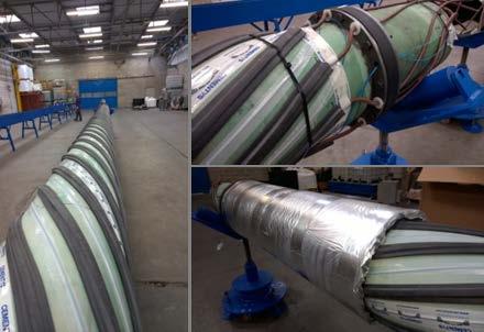
wrapped around the inner pipe. An electrical current is injected into these cables which, due to the resistive effect, generate heat. In Fig. 5-SAIPEM ETH PiP arrangement 6 Fig. 6-SAIPEM ETH PiP prototype Fig. 6-SAIPEM ETH PiP prototype turn, this heat is transferred by conduction to the steel inner pipe and the production fluid. In order to guarantee efficient control of the heating system in operating conditions, one or more fiber optic cables are also laid inside the 6 annulus, thus allowing real time monitoring of the temperature and pipeline strain along the pipeline. In order to ensure the heating of the overall flowline, each quad joint is fitted with these cables and continuity between two adjacent quad joints is obtained using an electrical connection system at each end. These connections are performed offshore on every quad-joint during J-Lay installation. The development and qualification of the technology and the related components began in 2014-2015. In this period, SAIPEM designed a 1st generation ETH PIP system featuring their field-proven sliding PIP concept and hosting heating cables capable of delivering the required power over 12 km with a voltage of less than 3 kV. The 1st generation technology passed a qualification program performed at SAIPEM facilities in France, achieving an overall maturity level of API 17Q TRL 4. In 2017, SAIPEM launched the development of the 2nd generation ETH PIP able to cover longer tiebacks thanks to a higher voltage (6.6 kV). The qualification program is ongoing at component level to reach a maturity level of API 17Q TRL 4 for each new component. A full scale qualification test on the integrated system will then allow for the achievement of an overall maturity level of API 17Q TRL 5 by the end of 2019. The 2nd generation ETH PIP is being developed for both J-lay and reel-lay installation methods to enable SAIPEM to propose the most suitable and cost effective solution for every project. Indeed, on one hand, the reel-lay installation method is well-known for ETH PIP in the Oil & Gas industry; on the other, the J-lay
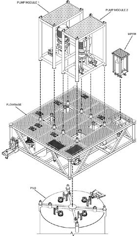
Fig. 7-Subsea boosting station layout and tie-in to production
installation method can unlock water depths, pipe size or geographical zones that are inaccessible at present with reeling. Moreover, the J-Lay can be more cost effective for very long distances where the reeling operation has to be split into many sections due to the limit set by the allowable packing and/or weight of the lay vessel.
Subsea boosting system
The use of a subsea boosting station in a long tieback is made necessary by the lack of pressure from the wellhead to overcome the combination of long distance and great water depth.
As a secondary effect, the presence of a subsea boosting station helps reduce the Gas Volume Fraction (GVF) of the fluid and limits the velocity based on the erosion criteria. Moreover, the pump usually increases the temperature of the fluid by a few degrees and this also has a positive effect on the system. life. Boosting is usually also required at mid/ end life to tackle the increase in water content. In the case of very deep fields, in addition to the subsea pumping system, gas lift could also be necessary to facilitate the management of the transient phase such as field restart or flow rate turndown, especially in late life.
Depending on the nature of the produced fluid, above all the GVF, a different configuration of the boosting pumps may be required: Hybrid (GVF<30%) or Multiphase (GVF>30%).
The sparing philosophy for the subsea pump usually ranges from 2x70% or 80% up to full redundancy.
In terms of architecture, the boosting station has been designed in such a way as to have a foundation pile supporting a flowbase and two retrievable Subsea Boosting Systems working in parallel, in order to fulfil possible requirements in terms of sparing philosophy.
The subsea boosting module configuration will be inspired by the following general design: Pump control is achieved using Variable Speed Drives (VSD) installed subsea in order to minimize the distance between the Pump Motor and the VSD itself, as described in more detail abve. The location of the pumping station in the field layout is based on: • the characteristics of the produced fluid • the location of the wells and gathering structure • the need to minimize the GVF at suction to improve efficiency • the attempt to minimize the cost of the electrical feeding system, if possible
The pumping station is normally the main consumer of subsea power so it is the driving factor in the design of subsea power distribution.
Subsea power distribution system
back development (subsea boosting, active heating, subsea water injection, subsea chemical injection) are usually characterized by a significant power demand and so they pose a real challenge in terms of the electrical power distribution from the topside facilities down to the subsea field. Typical long step-out developments include two boosting pumps (working in parallel usually with an operational philosophy of 2x70%), one or more sections of heated pipelines and other technologies that are coming onto the stage such as subsea water treatment/injection and subsea chemical injection.
The high power demand of this technology requires a distribution system for medium voltage (MV) electrical power from the topside facilities (FPSO or platform) down to the subsea equipment. This, together with the long distances, poses new challenges compared to traditional field development.
In a field development where the power chain equipment is located topside, each utility would require a dedicated electrical feeder, namely: • for active heating, an off-load tap changer step-up or step-down transformer, type of transformer depending on the point of connection to the PiP (at the riser base or far away from it), power cables, subsea step-down transformer (far from the riser base) • for each pump, a dedicated VSD, step-up transformer, power cables and step-down transformer
It is clear that, due to the high number of subsea utilities and the long distance, such a solution is likely to be extremely expensive and/ or not feasible. In addition to this, there are limits to the maximum distance between a Variable Speed Drive VSD and the controlled motor. At present, the longest installed chain for a subsea motor exceeds 40 km in the Asgard field. SAIPEM carried out simulation analyses, together with the vendors of the subsea power chain equipment, that ascertained the controllability of the motor up to 70 km.
Another aspect to consider is the significant impact that a topside based power architecture would have on an FPSO. In a brownfield development, an FPSO may not have such a large footprint available for all of the topside power system and may not have the required number of free positions available at the hang-off balcony or turret, therefore the traditional topside power architecture may not be feasible at all. Furthermore, the topside power distribution architecture could require a long FPSO shutdown.
Bearing in mind the above considerations, SAIPEM’s studies have focused on the use of subsea power distribution components that have been qualified in recent years by the two main suppliers (ABB and Siemens) and will be ready for the market in the near future. These components are the subsea Switchgear, subsea Variable Speed Drive (VSD) and subsea High Voltage Wet Mate Connectors.
These forthcoming technologies will drastically reduce the amount of power equipment installed topside as well as the subsea power cables between the FPSO and the subsea utilities with an ensuing reduction in equipment and installation related costs.
Other constraints that affect the architecture of the power distribution system for long tieback field development are: • retrievability of subsea components - systems must be as modular as possible and connected by wet mateable connectors.
The use of wet mateable connectors reduces intervention costs and duration and allow the use of intervention vessels with lower rated equipment since only the faulty module has to be retrieved • system branches will be individually isolable to avoid the propagation of faults
A key factor in the design of the electrical chain is the expected contemporaneity of the loads.
In the cases studied, the following operating philosophy was considered for the system, based on flow assurance analysis and considerations on the operational philosophy of the fields:
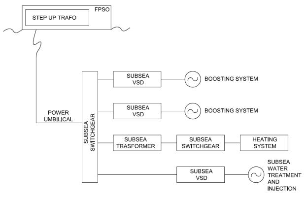
Fig. 8 Fig. 8 - Example of a Subsea Electrical Distribution System Architecture Example of a Subsea Electrical Distribution System Architecture Detailed electrical simulations and analyses have been carried out using the Electrical Transient Analyzer Program (ETAP®) Power Station software version 12.5.0. After the preliminary sizing of the power chain, a market study was performed to actual status of the technology of the subsea electrical component and to understand each system component. Vendor feedback showed that all of the main components of the subsea electrical chain are least TRL 4. 9
• Normal operation: pumps running at their maximum, while the heating system is switched off • Turndown phase: pump running at reduced rate, while part of the heating system is switched on • Start up: pump running at reduced rate, with part of the heating system switched on • Preservation: pump off, heating system switched on In all the above cases, the normal operating case dictates the sizing of the electrical chain. The typical values of the electrical power demand identified during the study are summarized below: • Max shaft power of the subsea pumps is around 3 MW for each pump • The heating system duty depends on specific flow assurance requirements. It may range between 0.5 MW and 1.5 MW for 50 km step out distance Given the above, the subsea power supply for the ETH system has no impact on the subsea power cable, as this is normally driven by the energy demand of the boosting station. By adopting a subsea electrical power distribution with a subsea switchgear it is possible to install just one subsea power cable, providing power at high voltage for all subsea utilities. In all cases studied by SAIPEM, the typical power demand of a 50-60 km step-out can be met with a transmission voltage that does not exceed 30 kV and with conductor cores in the range of 150 to 300 mm2. Since the VSD for the subsea motors can accept an input voltage of to 30 kV, no subsea step-down transformer is required for the pumps, so they can be connected directly to the subsea switchgear.
Subsea step-down transformers are needed for the ETH system, in order to adapt the transmission voltage to the exact voltage required by each function of the ETH system itself. Fig. 8 below shows the typical subsea architecture described above.
Detailed electrical simulations and analyses have been carried out using the Electrical Transient Analyzer Program (ETAP®) Power Station software version 12.5.0.
After the preliminary sizing of the power chain, a market study was performed to benchmark the actual status of the technology of the subsea electrical component and to understand the TRL of each system component.
Vendor feedback showed that all of the main components of the subsea electrical chain are at least TRL 4.
Subsea all electric control system
• Subsea Power and Communication Distribution Modules (PCDM) that receive the electrical power and distribute it to the subsea local control facilities (x-mas trees and manifold control modules) and receive the fiber optic signals, convert them to electrical signal and communicate with the subsea facilities local control equipment power typically ranging from 40-70W equipped tree, when in operation. for a SEM in idle mode, up to 300W for a SEM of a fully • Distribution of the chemical services by the main umbilical from the topside facilities down to one or more hydraulic disFor all-electrical actuators, the power is inversely dependent on the required operating times. tribution units located in the field, from SAIPEM calculated that, to achieve performances comparable to hydraulic actuators, a drop type all-electrical actuator for a 5-1/8” gate valve would require at actuator terminals which the chemicals are distributed to the manifold and x-mas trees by means of flying leads or infield umbilicals between 3kW and 12kW for operating times of between 120” and 30”. In addition to this must be considered that the brushless motor electronic boards have constant power absorption The first result of introducing an all-electric typically of between 5W and 15W. This means that an XT with 15 valves would have a cosystem is the elimination of the low and high minimum power demand up to 225W. pressure supply lines. Bearing in mind the above, the power supply architecture becomes of paramount importance. SAIPEM Fig. 9 – Electrical Actuators power supply architecture identified the following philosophies, each having its pros and cons:
The hydraulic and chemical lines are among the most burdensome components of the subsea control system distribution CAPEX, accounting for up to 80% of the cost of a subsea control umbilical.
For this reason, a key optimization to reduce subsea control system procurement and installation costs is the elimination of the hydraulic and chemical lines from the umbilicals and this can be achieved by adopting all-electric control systems, where the valves are no longer actuated by hydraulic power but by electrical motors.
In recent years various players have developed or are developing all-electric systems and a few of them have been already installed and are being operated by Oil Companies, creating reassurance that the technology has gained sufficient maturity for a wider use in the present or near future.
The potential benefits that they can provide in the context of a long tie-back have been evaluated by SAIPEM including the all-electric control systems in the studied innovative schemes. Several projects have been carried out together with subsea equipment manufacturers (e.g. Siemens) to design and optimize control system architectures, perform verification analyses of the chosen design and identify technology gaps and future areas of development. In this respect, SAIPEM has been active for several years, conducting a development program in cooperation with Siemens for the subsea all-electric control system for the SAIPEM SPRINGS® water treatment and injection system and for subsea separation. SAIPEM-Siemens all-electric control system is currently under qualification and is due to achieve TRL 4 certification by the 2nd quarter of 2019. The results and experience gained during the design and industrialization of SPRINGS have been transferred to long subsea tie-back field development.
The overall architecture is the same as a traditional E/H control system with the hydraulic actuators replaced by electric ones, with: • Topside located control equipment: MCS,
EPU and modem unit connected via the ethernet network and an open protocol such as MDIS with the host DCS • Subsea power cables and fiber optic cables to provide to the subsea control equipment the necessary dual redundant electrical power and communication
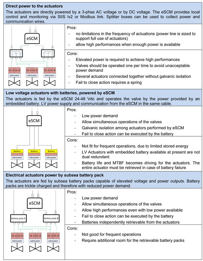
Fig. 10 - Example of Subsea Control system Architecture
Mod em UTA
ETH Electrical Trace Heating MAN Manifold PCDM Power and Communication Distribution Module SWG Subsea Switchgear UTA Umbilical Termination Assembly VSD Subsea Variable Speed Drive XT X-mas tree SWG
UTA UTA PCDM
XT XT
PCDM XT XT
MAN
XT XT
VFD ETH
M
VFD M
MV power cable (3-phase AC) LV power cable (3-phase AC) Control power & Comms cable Fibre optic cable Transformer
By adopting an all-electric control up to the x-mas trees it is possible to eliminate the low and high pressure control lines (typically 2 + 2) from the main umbilical, the hydraulic subsea distribution module, flying leads and infield umbilicals. SAIPEM calculated that on a typical steel tube umbilical for an oil field, the elimination of the control lines would save between 10% and 15% on the cost of the main umbilical and between 15% and 20% on the infield umbilicals. A further significant optimization can be obtained by introducing subsea chemical storage and injection facilities that enable a further reduction of the umbilical tubing, see the following section. The most relevant factor in system sizing is the power demand of the subsea control system equipment, which is significantly influenced by the required performance of the electrical actuators and by the architecture selected for their power feeding. In a traditional E/H control system, the power demand of a x-mas tree or a manifold can be determined knowing the current drawn by each equipment in, or connected to, the SEMs, with power typically ranging from 40-70W for a SEM in idle mode, up to 300W for a SEM of a fully equipped tree, when in operation. For all-electrical actuators, the power is inversely dependent on the required operating times. SAIPEM calculated that, to achieve performances comparable to hydraulic actuators, a drop-in type all-electrical actuator for a 5-1/8” gate valve would require at actuator terminals a power between 3kW and 12kW for operating times of between 120” and 30”. In addition to this power, it must be considered that the brushless motor electronic boards have constant power absorption typically of between 5W and 15W. This means that an XT with 15 valves would have a constant minimum power demand up to 225W.
Fig. 10 - Example of Subsea Control system ArchitectureBearing in mind the above, the power supply architecture becomes of paramount imporEven although this is an established architecture, the presence of the fibertance. SAIPEM identified the following philos- optic link, necessary due to the long distance, enables several important features and future improvements. ophies, each having its pros and cons: With an ethernet infrastructure reaching any point in the field, it would be possible to run several From the studies carried out it emerged that no protocols such as a deterministic industrial ethernet for fast control loops (<10ms), condition monitoring protocols or power system management protocols based on IEC 61850. “fit-for-all” design can be identified among the alternatives indicated above. A further interesting development is the possibility of implementThe direct power architecture best suits appli- ing a safe protocol to be used with SIL compliant devices. This would consist of a safety overlay working over the standard ethernet cations requiring high power combined with frequent operations of the valves. Typically, equipment via a technique known as “back channel” and that would allow this is the situation of subsea factory applica- for the construction of safety chain up to the x-mas tree. tions. A possible interesting future development is the possibility Valves at ILTs and PLETs are infrequently opof having all the sensors and electrical actuators in the manifolds, x-mas trees or PLETs, directly implementing an Ethernet protocol. erated and do not normally have strict performance requirements so SAIPEM proposes 12 LV actuators with embedded batteries for this type of application, with the actuators tied back to the closest eSCM. The capability of accepting 24-48 Vdc makes this solution feasible also as a retrofit solution, in the presence of E/H X-mas trees. Direct power can be considered as well if dual redundancy is required and as long as the available power is sufficient for acceptable operating times. The all-electric x-mas trees represent a factor of uncertainty as today there is no consolidated design. Albeit all of the above alternatives can be adopted for x-mas trees and manifolds, direct power seems to have several disadvantages. In a cluster populated by a manifold, 4-6 production wells and other water injection wells, direct power feed would require very large and powerful electrical distribution units to switch and isolate the utilities and large conductor diameters in the umbilicals to avoid excessive voltage drops. On the contrary, all-electric x-mas trees with subsea batteries (either embedded in the actuators or centralized), would have a power demand that is similar to traditional E/H systems, greatly simplifying the power management of the subsea control system. Over long step-out distances, efficient transmission of electrical power to the control equipment is necessary to limit the cost of electric cables. The situation is aggravated by the all-electric control system, whose power demand is inherently higher than a traditional E/H one. Several electrical distribution methods were investigated. For these high power demands, it is necessary to increase the transmission voltage (typically to 3kV) and to consider quite large conductors, such as 35-50mm2, to avoid unacceptable voltage drops. The AC voltage was preferred, as the conversion is generally simpler. In addition to the above, the use of AC voltage is a good match with the medium voltage already present in the field to provide power to the boosting station and the heated pipelines. SAIPEM believes that the most straightforward way for control system power supply for long tie-backs is to obtain the low voltage from the MV power where possible. This will provide very high power and at the same time eliminate the need for large low voltage conductors for the control power through the entire length of the main umbilical. The communication distribution architecture for a long subsea tie-back development, either with E/H or all-electric control system, can be considered consolidated, consisting of fiber optic communication for the long-step distance between the topside or shore facilities up to a communication distribution unit (typically integrated in the PCDM) in the field. From the communication distribution unit, the communication signals are converted to electrical signal and transmitted to the manifold and to the x-mas trees. Even although this is an established architecture, the presence of the fiber optic link, necessary due to the long distance, enables several important features and future improvements.
With an ethernet infrastructure reaching any point in the field, it would be possible to run several protocols such as a deterministic industrial ethernet for fast control loops (<10ms), condition monitoring protocols or power system management protocols based on IEC 61850.
A further interesting development is the possibility of implementing a safe protocol to be used with SIL compliant devices. This would consist of a safety overlay working over the standard ethernet equipment via a technique known as “back channel” and that would allow for the construction of a safety chain up to the x-mas tree.
A possible interesting future development is the possibility of having all the sensors and electrical actuators in the manifolds, x-mas trees or PLETs, directly implementing an Ethernet protocol.
Subsea components would connect directly to the ethernet network by means of a subsea ethernet switch, like those normally present in the communication distribution units, and be directly controlled and monitored from topside, without necessarily being connected to a SCM.
Subsea chemical injection system
The traditional approach adopted to supply chemicals to a subsea tieback is to position the chemical injection pumps on the topside platform/FPSO and the associated chemical lines in a high pressure umbilical down to the subsea injection points.
In the development of a long tieback, because of the very long distance from the receiving facilities, the cost and complexity of the traditional umbilical grows and pressure drops and control of chemical delivery pressures and flowrates through such a long umbilical can be extremely challenging. The consequence is high diameters and big unit weights umbilical that can create packing and installation challenges. These factors have led to the need to review this architecture to make the development of a long tieback sustainable from the point of view of both cost and technology. To overcome these major criticalities, the idea is to move the chemical injection system subsea, possibly close to the injection points.
The advantages of this solution are: • Simplification of the umbilical due to the elimination of the steel tubes for the (if coupled with “all electric control” allows the elimination of all steel tubes) transport of chemicals • Simplification of the installation procedures • Reduction of topside space requirements by placing the chemical injection package (storage tanks, pumps, regulation systems, etc.) subsea.
Over recent years, SAIPEM has mapped the typical chemical demand for a representative size of oil fields, with the main aim of defining a subsea chemical injection system architecture and the related main components.
The main result of this exercise is the definition of a concentrated architecture for subsea chemical storage and injection facilities to be located close to the wells. The overall system can comprise modules individually dedicated to one specific chemical that include the pump system, the tank and the relevant control and power system.
As far as we are aware, there is still no real case of permanently installed subsea chemical storage and injection systems but there are many players that are working on different technologies to make this feasible. SAIPEM also is active in this field to identify and qualify the needed technologies.
Subsea water treatment and injection system
Water injection (either Raw Sea water or Treated Sea Water) can be managed by the Total/ SAIPEM/Veolia SPRINGS® unit powered through the subsea electrical distribution system.
This solution avoids the installation of the entire water injection loop and the related modification to the topside facilities. The SPRINGS station can be located at the wellhead area to minimize the cost of water injection line.
CONCLUSIONS
The studies and analyses performed on both study cases and real fields, whose main results are summarized in this paper lead to the following main conclusions:
• New field development architectures for challenging subsea fields like oil long subsea tiebacks can be achieved by combining different building blocks, each expressing a suitable technology for a specific function (Product Transportation, Control, Power, etc.), in the optimum architecture that minimizes costs;’ • The best selection and combination of technologies, along with the overall architecture is strictly linked to the flow assur-
ance peculiarities of the field itself and its topology; • Technology has advanced greatly in terms of technical readiness in recent years. In particular, Pipeline Heating
Systems, Subsea Power Distribution
Systems and All-Electric Control Systems are now field-proven or at least ready to be integrated in a complex system; • The above technologies, combined with Subsea Water Treatment and Injection, like SPRINGS®, and Subsea
Chemical Storage and Injection, can significantly improve the development scheme enabling feasible and cost effective development of subsea fields far from the product receiving/treatment unit; • From an economic point of view, it has been noted that, in the case of a long step-out distance, economic benefits in terms of CAPEX and OPEX can be obtained by adopting a combination of these technologies. It has also been noted that the flexibility offered by new development schemes based on the new technologies described here can significantly improve plant operations in transient conditions, at startup and at shut-down and can consequently reduce the OPEX. • AIPEM is active in the development of new technologies for challenging subsea field developments, in particular long subsea tieback distances and is also a knowledge owner and integrator of new technologies developed by others.
ABBREVIATIONS
DCS: Distributed Control System DEH: Direct Electrical Heating EPU: Electrical Power Unit ETH: Electrical Trace Heating GVF: Gas Volume Fraction HAT: Hydrate Appearance Temperature MCS: Master Control Station PCDM: Power & Control Distribution Module PiP: Pipe in Pipe SCM: Subsea Control Module SEM: Subsea Electrical Module TRL: Total Readiness Level URF: Umbilical Risers Flowlines VSD: Variable Speed Driver WAT: Wax Appearance Temperature


