The Burnley Family Reconciliation Centre
1
Portfolio | Saif Hajazi Studio 3.2 | &rchitecture

Burnley has the second highest divorce rate in the entirety of Lancashire at 10.33%, higher than the national average of 3%. For every 100 residents in Burnley, 10 are divorced.
Daniel and Kelly Live in Burnley, UK, where divorce rates are 10.3%, higher than the national average of 9.3% in 2021. This means for every 100 residents in Burnley, 10 are divorced.
The Burnley Family Reconciliation Centre allows Daniel to spend time with his children, Jack and Amelia. It serves as a safe haven for visitation and repairing his relationship with Kelly. Kelly waits for Daniel in the reception area.

Daniel and Kelly initially hesitate to talk to each other, but as their children laugh and play, the tension eases, and they start interacting with each other through their children, facilitated by the buildings activity walls.


According to a report conducted by the Lancashire city council in 2021 using the English indices of deprivation, Burnley is classified as the most deprived town in Lancashire. This existing deprivation, alongside the present cost of living crisis puts further strain onto families, leading to higher levels of divorce and family separation.


As Jack and Amelia join the other children in the building to play, Daniel and Kelly decide to go upstairs to the reflection garden. This peaceful space allows them to have a private conversation about their relationship.


Daniel and Kelly openly express their regret over the way their marriage ended. They both acknowledge the importance of raising their children in a nuclear family and are willing to take gradual steps towards reconciliation.
As the day winds down, Daniel lovingly embraces his children and bids them farewell. Just as he is about to leave, Kelly expresses her enjoyment of the day and suggests the possibility of arranging similar gettogethers on a weekly basis. She appreciates seeing Daniel actively engaged in playing with the children once again.
After several visits, Daniel and Kelly rekindle their relationship, breathing new life into it. Kelly agrees to let Daniel move back home and help raise their children, allowing them to live together as a nuclear family once more.
The Burnley Family Reconciliation Centre plays a crucial role in revitalising broken marriages, fostering interactions within its interactive environment without the need for formal counselling.


Through materiality, the building aims to demonstrate a personal journey from darkness to light, symbolising a transition from a trapped a state to a place of sanctuary and refuge.

The use of garden spaces promotes spaces of contemplation, creating spaces for private conversation between couples in a serene and secure environment.


The activity walls challenge traditional methods of reconciliation through physical form, promoting engagement between parents and children, easing tensions and promoting conversations.
With structures that evoke the synthesis of human emotional expression in built form, it essential to offer spaces of security privacy, prioritised in the RIBA sustainable outcomes guide.
Economic Actors
Site Connections - Figure Ground
Street Network - Route to Site

Street Network
Since my economic actors are families, they naturally reside in suburbs adjacent to the town centre. By beginning to establish connections, I can construct a network that depicts the common interconnections of my economic actors' locations.
Possible site accessibility difficulties can be detected by research on street networks and establishing access to the place. Thankfully, my economic actors can walk to the site, which is less than a 15-minute walk away. You must, however, cross A roads, which might operate as site restrictions for pedestrians.
Greenery and Rivers - Boundaries to Site RIBA Sustainable Outcomes - Project Goals


Sustainable Land Use & Ecology
• Leave a site in a better regenerative ecological condition
• Priortitise Brownfield Site Selection
Rivers and Greenery
Burnley
The area of Brunshaw is bounded by the Leeds and Liverpool Canal, which is there only one main crossover towards the Site. This acts as a boundary, that can make access to the site limited. Moreover Whittlefield is isolated by the M65, and requires walking through an underpass to get towards the site, once again hindering accessibility to the site.
• Create a range of green spaces
Sustainable Communities and Social Value
• Create secure places for privacy
• Create inclusive spaces for social interaction
• Prioritise place-making that expresses identity
Good Health and Wellbeing
• Provide a strong visual connection to the outside
• Design spaces that are inclusive and acessible
• Design spaces to adaptive thermal comfort standards
Linking the masterplan to the RIBA outcomes, it’s vital to establish a site that positively influences the surrounding locale, creating sustainable communities that facilitate social interaction, and prioritising sustainable land use, and user wellbeing to ensure the site has a positive influence on the surrounding community.

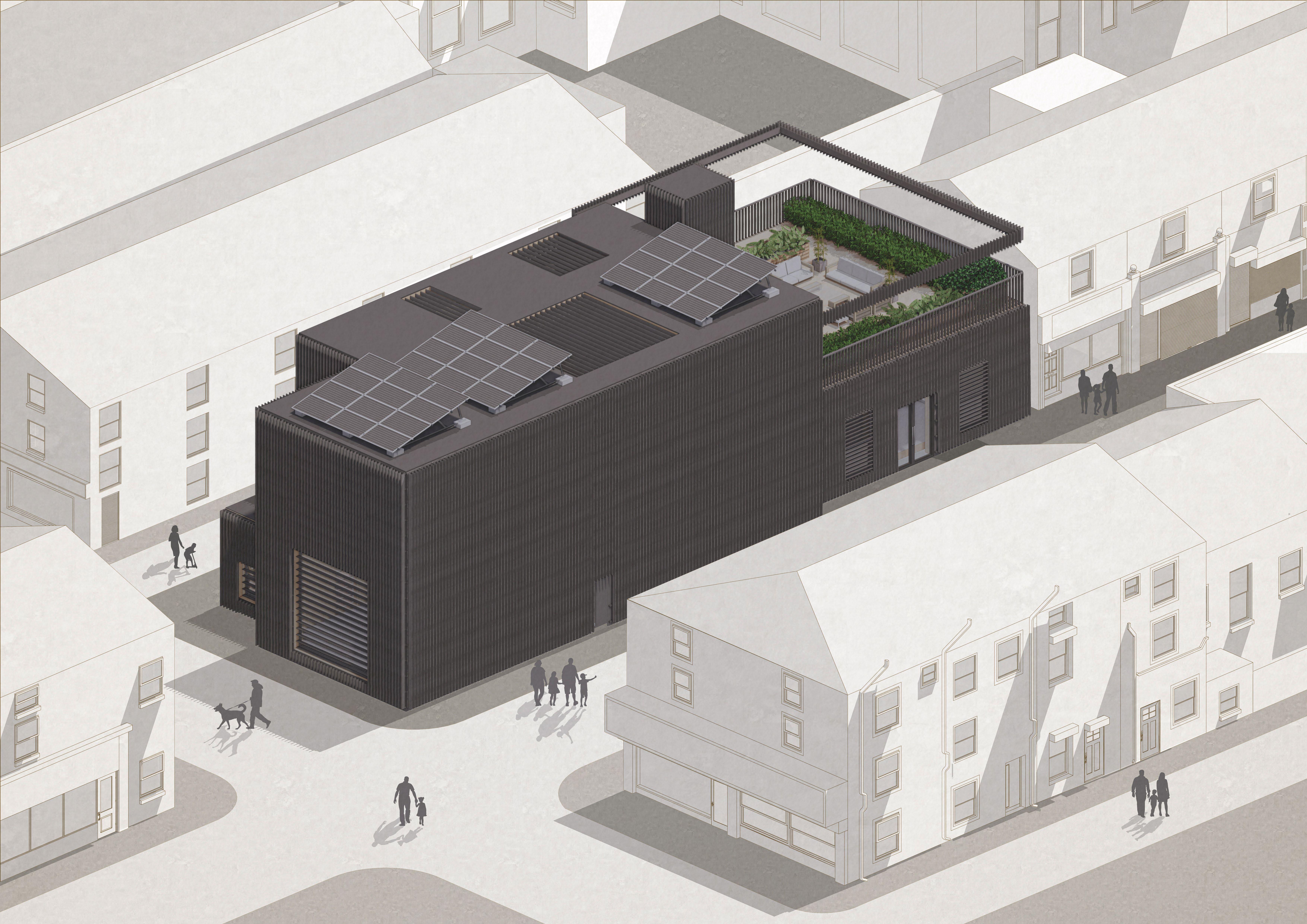
In the planning stage of the building, I made the conscious decision to build a structure that sits within the exiting urban fabric and built environment. To accomplish this, I opted to match the dark colour tones of the Burnley Market, a key sub site in the project, to create a distinct visual connection between the two buildings. So while the building stands out in the immediate vicinity, it aims to create a wider connection through materiality to Burnley Market, to make the building sit comfortably within the urban fabric.


 Ground Floor
1:200@A4
1. Lobby Space
2. Activity Walls
4. W.C
5. Indoor Reflection Garden
6. Outdoor Roof Garden
3. Breakout Spaces
4. W.C
First Floor
1:200@A4
Ground Floor
1:200@A4
1. Lobby Space
2. Activity Walls
4. W.C
5. Indoor Reflection Garden
6. Outdoor Roof Garden
3. Breakout Spaces
4. W.C
First Floor
1:200@A4


Lifespan: 60 Years
Embodied Carbon: 0.437 kgCO2e/kg
Locally Sourced: Offsite
Prefabrication from Derby - 115 miles from site
Post Life Reuse: can be re-used, commonly turned into biomass
Deconstruction: By using screws and bolts rather than adhesives, CLT can be dismantled
Lifespan: 100 Years
Embodied Carbon: 0.9 kgCO2e/kg
Locally Sourced: Sourced within Burnley - 1.6 miles from site
Post Life Reuse: can be crushed and reused for other purposes
Deconstruction: cannotbe dismantled
Lifespan: 50 Years
Embodied Carbon: 1.8 kgCO2e/kg
Locally Sourced: Sourced
From Preston - 30 miles from site
Post Life Reuse: Ground into powder and reused for other products
Deconstruction: can be removed if assembled using screws.
Lifespan: 50 Years
Embodied Carbon: 0.14 kgCO2e/kg
Locally Sourced: Not grown in the UK - can be sourced from within 30 miles in Lancashire
Post Life Reuse: Can be Reused after Service life Deconstruction: can be removed if assembled using bolts and screws.
Lifespan: 100 years
Embodied Carbon: 0.512 kgCO2e/kg
Locally Sourced: Locally Sourced From Preston,20 miles from site
Post Life Reuse: Glulam can be reused and recycled after its service life Deconstruction: Glulam can be deconstructed through using screws and bolts.
Lifespan: 60 Years
Embodied Carbon: 0.3 kgCO2e/kg
Locally Sourced: Preston - 11 miles from the site
Post Life Reuse: can be re-used if maintained Deconstruction: Held on by screws and bolts can be easily dismantled after service life.
Lifespan: 100 Years
Embodied Carbon: 1.3 kgCO2e/kg
Locally Sourced: Sourced within Burnley - 5.5 miles from site
Post Life Reuse can be recycled and reused for other purposes
Deconstruction: can be dismantled through bolts
Lifespan: 30 Years
Embodied Carbon: 0.5 kgCO2e/kg
Locally Sourced: Sourced within Blackburn - 11 miles from site
Post Life Reuse: can be recycled and reused if maintained
Deconstruction: can be dismantled if part of a unitised envelope system
Lifespan: 25-30 Years
Embodied Carbon: 0.9 kgCO2e/kg
Locally Sourced: Grown in Scotland - Sourced in Lancashire - 30 miles
Post Life Reuse: Can be Reused if maintained Deconstruction: can be removed if assembled using bolts and screws.
Lifespan: 25 -50 Years
Embodied Carbon: 0.3 kgCO2e/kg
Locally Sourced: Lancashire- 24 miles from site
Post Life Reuse: may be reused if maintained - complex to recycle Deconstruction: Can be dismantled if a part of a rainscreen system
Lifespan: 50 Years
Embodied Carbon: 0.1 kgCO2e/kg
Locally Sourced: Sourced within Blackburn - 11 miles from site
Post Life Reuse: may be reused if maintained Deconstruction: Can be dismantled if a part of a unitised envelope system

Lifespan: 50 -100 Years
Embodied Carbon: 1.1 kgCO2e/kg
Locally Sourced: Sourced from Manchester - 30 miles from site
Post Life Reuse: Cannot be reused or recycled after its service life
Deconstruction: Cannot be easily dismantled and is considered hazardous
Lifespan: 20 years
Embodied Carbon: 6kgCO2e/kg
Locally Sourced: Locally Sourced From Blackburn 12 miles from site
Post Life Reuse: Possible - but a very complex process and uncommon Deconstruction: can be dismantled when assembled as a rainscreen fixture
Lifespan: 100 years
Embodied Carbon: 2.5kgCO2e/kg
Locally Sourced: Locally Sourced From Bolton- 22 miles from site
Post Life Reuse: Highest recycling rates of any metal 90% of all zinc recycled Deconstruction: easily disassembled in a rainscreen.
Lifespan: 60 Years
Embodied Carbon: 1.1 kgCO2e/kg
Locally Sourced: Supplied from Lancaster, 40 miles from site
Post Life Reuse: Can be Reused into other products
Deconstruction: can be removed if assembled in a unitised envelope
Lifespan: 50 Years
Embodied Carbon: 1.3 kgCO2e/kg
Locally Sourced: Supplied from Blackburn, 12 miles from site
Post Life Reuse: Can be Reused into other products
Deconstruction: can be dismantled - caution needed as it is irritant.
Timber Cladding
Locally Sourced Sitka Spruce
Windows
Ecosense Glass Triple Glazed
Window Frame
Recyled Aluminium Frame
Black Falun Pigment
Applied Over Timber Cladding
Alternative to Charring
Sheathing
18mm OSB Panel
Ashcrete
Activity Walls
Sustainable Concrete Alternative

Primary Structure
Cross Laminated Timber Internal Wall Finish
Locally Sourced Prefabricated Panels
Knotted Cedar
Locally Sourced Planter Boxes
Floor Finish
White Stained Cork
Insulation
Wood FIbre Based Insulation
Locally Sourced
Adopting a circular economies perspective, a simplified and minimal palette of materials offers a number of benefits. This approach reduces the distance required to transport materials, which in turn leads to a decrease in embodied carbon. Furthermore, incorporating recycled and reclaimed materials, as well as by-products from other industries, contributes to a lower embodied carbon structure that prioritises the use of local and sustainable materials. By adopting this approach, the design aims to enhance the ecological state of the site and aligns with the RIBA Sustainable Outcomes Guide. Overall, this approach supports a regenerative and locally-centric approach to building that prioritises environmental sustainability.


Through the buildup of the envelope and floors, there is a conscious decision to prioritise wood based and bio-based materials, as they can be locally sourced, are can facilitate carbon negative design. Furthermore, once these materials reach their end of service life, they can be easily reused and recycled for other purposes.


1. EPDM Roof Membrane
2. 200mm Wood Fibre Insulation
3. Timber Roof Joists
4. Insulation Between Joists
5. 200mm CLT Structure
6. Suspended Ceiling Roof Joists
7. 25mm Stained Cork Ceiling
8. Aluminium Roof Flashing
By locally sourcing materials, the embodied carbon of the material is reduced through transportation and distribution. This can contribute to more sustainable and environmentallyfriendly practices, as well as supporting local economies and communities.
Trees absorb CO2 from the air and store it in their tissues. When trees are harvested, the carbon remains stored in the wood. By maximising the use of timber structures, the carbon is sequestered in the building materials rather than being released back into the atmosphere, facilitating carbon negative design.

By using circular economy principles, There is an aim to design the structure with its end of use life as a priority, by creating the building with materials that can be easily recycled and reused , as well as responsible sourcing of materials through reclamation and by-products of other industries.

To minimise the release of embodied carbon at the end of the buildings lifespan, allowing the building to be disassembled by avoiding the use of adhesives and permanent fixtures allows for the materials in the buildings to be recycled and reused once the building is dismantled.
9. 12mm Grey Stained Cork Floor
10. 200mm Wood Fibre Insulation
11. Suspended Timber Floor Joists
12. Insulation Between Joists
13. 200mm Structural CLT
14. Suspended Ceiling Joists
15. 25mm Stained Cork Ceiling
16. Aluminium Joint Plate
17. External Sitka Spruce Cladding
18. Horizontal Battens

The interior materiality of the structure has been revised to align with a circular economy design and carbon-negative construction approach. The use of loadbearing CLT walls eliminates the need for plasterboard, reducing the building’s carbon footprint. The flooring now features white-stained cork on a timber suspended floor, further decreasing embodied carbon.

The outdoor garden follows the RIBA sustainable outcome principles, prioritising good health and well-being, sustainable communities, and social value. It includes visual connections to the surroundings, diverse green spaces, secure areas for privacy, outdoor planted spaces, and adheres to part K with a minimum 1100m railing height. Additionally, a large spanning element provides panoramic views while ensuring occupant privacy.

The reception space features CLT as the main structural and interior wall material, demonstrating a restrained material palette. The staircase is also made entirely of CLT. This design approach prioritises low embodied carbon construction and maximises natural light for an engaging atmosphere. The building’s exterior showcases black timber cladding, while the interior emphasises light-filled spaces and highlights CLT in the design.


The Hidden Embodied Carbon Of Material Production

Material extraction significantly contributes to the accumulation of hidden embodied carbon emissions, as the energy-intensive extraction and transportation of raw materials result in the release of greenhouse gases that are often overlooked in traditional carbon accounting methods.
The production of materials is a significant contributor to hidden embodied carbon emissions, as the energy-intensive procedures associated with material manufacturing, such as refining, processing, and shaping, result in the release of greenhouse gases.

The transportation of materials from the location of extraction to the site of manufacturing and then to the building site, are hidden emissions that are embedded in the embodied carbon of a material. By locally sourcing, we can significantly reduce the amount of emissions caused by transportation.


The Solution: Sustainable, Locally Sourced Manufacturing | Cladding Manufacturing Sequence


As reported in the UN global statistics report in 2017, embodied carbon emissions account for 63% of a materials whole life carbon emissions. Alongside mitigating operational carbon, it is vital to reduce the “hidden” embodied carbon emissions.
The
Total Embodied Carbon Of 4x4m Fragment = 256.2kg CO2e
Total Carbon Savings Through Sequestration = 3731kg CO2e
Total Envelope Embodied Carbon After 60 years = -3474.8kg CO2e
- The calculations were taken from a 4000mm height fragment of the envelope
- All timber based elements were sourced sustainably, utilising sustainable forest management schemes such as FSC.
- All envelope elements were locally sourced, and had a transportation distance of 30 miles maximum.
- All finishing and manufacturing methods were industry standard, and used fossil fuels in the manufacturing of the product

Trees, as biogenic carbon sinks, absorb carbon dioxide through photosynthesis. The height and age of a tree determine the amount of carbon it can store. Using sustainably managed forests is crucial to maintain the carbon cycle by replanting replacement trees.


Timber used in construction retains the carbon dioxide stored within it, as wood is a stable material that doesn’t readily decompose. About 50% of dry wood’s composition is carbon dioxide, which remains stored in the building structure rather than being released into the atmosphere.
A CLT wall that is 4000mm tall and 200mm thick, transported 30 miles, sourced sustainably, uses standard finishing methods and is made from Douglas Fir would sequester an estimated 1.5 tonnes of carbon over 60 years.


The CLT would be carbon negative by 1340kg CO2e over 60 years which is calculated by subtracting the embodied carbon of 160kg from the total carbon sequestration of 1500kg.
Carbon Negative OSB
The longer timber elements in a building are used, the more carbon they can sequester. This enables buildings to become carbon negative over their service lifespan, offsetting the embodied carbon associated with manufacturing, finishing, and transportation of the material.
Timber products can be reused or recycled into various items like paper, furniture, and packaging at the end of their service life. This helps maintain the stored carbon and contributes to the circular economy, as the timber is continually repurposed instead of being left to decompose or discarded in landfills.
The OSB board has an embodied carbon of 32kg CO2e. The board would sequester an estimated 384kg of carbon over 60 years, which is calculated by multiplying the annual sequestration rate of 6.4kg by 60 years.
The OSB Board would be carbon negative by 352kg CO2e over 60 years. This is calculated by subtracting the embodied carbon of 32 kg from the total carbon sequestration of 384kg.
The Sitka spruce cladding has an embodied carbon of 57kg CO2e. The cladding would sequester an estimated 1.33 tonnes of carbon over 60 years, which is calculated by multiplying the annual sequestration rate of 22.5kg by 60 years.

The cladding would be carbon negative by 1293kg CO2e over 60 years. This is calculated by subtracting the embodied carbon of 57kg from the total carbon sequestration of 1350kg.
The Wood Fibre Insulation board has an embodied carbon of 4kg CO2e. The board would sequester an estimated 750kg of carbon over 60 years, which is calculated by multiplying the annual sequestration rate of 12.5kg by 60 years.


The Insulation Board would be carbon negative by 746kg CO2e over 60 years. This is calculated by subtracting the embodied carbon of 4kg from the total carbon sequestration of 750kg.

Using exposed screws rather than concealed methods promotes easy dismantling of the facade at the end of its service life.
Metal bracket and screws concealed in the floor and ceiling spaces, allowing for easy deconstruction and minimising waste.
CLT Wall to Floor Junction | 1:5@A4
A balloon ledger joint with a steel angle between the wall and floor and an engineered wood block that facilitates the connection of the floor to wall with screws


A practical method for easy disassembly is the bracket screw system, using L-shaped brackets and screws to secure floor and wall joints. This system offers substantial strength for heavy loads and quick installation to minimize on-site waste. However, it may be susceptible to corrosion and can present challenges when installed in tight spaces.


While this may come at an “aesthetic cost” it promotes function over form through the preservation of materials by avoiding permanent fixtures.
Within a rainscreen system, various methods can be used to attach the cladding, such as screws, concealed clips, and sliding brackets. In this case, I have chosen screw attachment for its quick and efficient construction and dismantling. To maintain aesthetic appeal, the screw heads can be PVD coated in black to match the facade’s black timber rainscreen.
The balloon ledger joint is an alternative option, using screws and a wooden block to facilitate easy dismantling. It offers sustainability advantages by utilising timber and fewer materials. However, this system has lower load-bearing capacities compared to metal brackets and requires careful installation to avoid instability.


In the “Plan for Use” stage of the RIBA plan of work, designing for deconstruction is emphasised. By incorporating universal methods like screws and brackets, waste is minimised and efficiency is maximised. The same tools can be used for both assembling the facade and the loadbearing CLT frame. This approach reduces energy consumption and eliminates the need for specialised equipment.


CLT Prefabrication
Cladding Prefabrication

Wood Fibre Insulation Prefabrication Floor Joists Prefabrication

The use of a panelisted CLT primary structure allows for the offsite prefabrication of the materials cut to precise dimensions, minimising onsite wastage.


The timber cladding can be prefabricated and painted offsite to ensure a precise finish under factory quality control conditions, ensuring minimal waste and high finishing standards.
Wood fibre insulation allows for the sustainable sourcing of offsite insulation, as it composed of waste wood products. These are prefabricated into panels and installed onsite.

As all the floor joists are a standardised measurement, these can be efficiently cut to size off-site, minimising waste and increasing the speed of production.

In RIBA Stage 5, it begins with the erection of the slab foundation as the site sits on loadbearing limestone, making it ideal for the building’s loadbearing capacity.
Secondly, the ground floor can be constructed, consisting of the panellised CLT structure and floor joists. The internal walls are also loadbearing, as they uphold the first floor mezzanine floor.
Next, construct the ground floor ceiling, first storey floor joists, panellised primary CLT structural walls, and staircase installation with easy crane access into the staircase core without a roof.

After both floors are constructed, the first floor ceiling and the CLT roof slabs can be installed. The veneer flooring of the outdoor garden space can also be installed at this stage.

Following the installation of the Roof Slabs, the roof can be finished, through the installation of roof joists, insulation and roof flashings and an EPDM roof membrane.
Next is the installation of the wall buildup, insulation, breather/ vapour layers and sheathing prior to the installation of the cladding. At this stage, doors and windows can also be installed.
As the structure of the building is now complete, the transition into the hadover stage begings and into the final finishes. The rainscreen cladding is installed around the building.
Finally, the building enters the use stage, where floor finishes, furniture and building services are installed. A post occupancy can be carried out to determine the buildings success.
1. Foundation Erection 5. Roof Finishes 6. Wall Buildup, Doors & Windows 7. Cladding Installation 8. Floor Finishes, Services & Furniture 2. Ground Floor CLT Panels & Floor 3. Gr-Flr Ceiling, 1Flr CLT Panels & Floor 4. First Floor Ceiling and Roof SlabsPrevious First Floor Layout


Previous Exterior Visualisation


Revised West Perspective Section
In my previous iterations of plans, I had not devised a space for the access to building services such as boilers, electric and heating/cooling systems, which are necessary to house the buildings mechanical systems
In the exterior of the building, I utilise different heights of spaces to create visual interest to an otherwise “boxy” building. This is evident through the ancillary coor having a lower ceiling height than the main public space.
The section further demonstrates the implementation of the plant space on the first floor above the breakout room. This only leaves one space at a smaller ceiling height, but still adds variation to the buildings shape.

As my building has two separate cores, ancillary core and a public one, I was able to extend the ancillary core to include a plant room, whilst minimising lost void space in the mezzanine. As a result I only had to extend the mezzanine by 1200m to fit space for the door, as the plant space sits ontop of the ancillary core.
As I had to extend the ancillary core to incorporate the plant space on the first floor, this does slightly diminish the varying heights of the spaces, but it isn’t as noticeable as I first envisioned when adding the plant space
The section on the East side of the building shows that the mezzanine void space remains largely uninterrupted due to separating the building into two separate cores, as the first floor only needed to be extended by 1200mm to include the door into the plant space.


Open Solar Shades
Closed Solar Shades
Summer Strategy


Solar shades play a fundamental part in the heating and cooling strategy of the building, and can save between 10-50% of a buildings energy cost. They can also improve user comfort by reducing glare.

Open Solar Shades
Closed Solar Shades
Summer Strategy
DaytimeLouvres Closed
In summer, closed louvres block sunlight and reduce the cooling load. The windows are opened to allow for passive ventilation.


Night /Morning Louvres Open

The solar shading louvres are opened in the early morning and at night to let cool air in and let warm air out, facilitating a passive heating and cooling system in summer.
Winter Strategy
The activity walls are in a south facing area, where it receives direct sunlight during the early evening from 4-6pm. The solar shades aid in user comfort by reducing glare, allowing for better clarity.
The reflection garden uses a large roof skylight, which is prone to direct sunlight throughout the early afternoon from 11am-2pm. The solar shades reduce glare and improve user comfort.
Solar shades reduce energy costs by reflecting sunlight and preventing overheating. Sunlight emits an average of 32,000 to 100,000 lux, with the south-facing window in the visual reaching 89,000 lux. Closing the solar shading halves the lux, improving userccomfort and cutting energy expenses.


Night /Morning Louvres Closed
In winter, the louvres are closed during the coldest parts of the day to reduce heat loss, preserving and distributing the stored heat in the buildings CLT thermal mass during cooler periods of the day.


Winter Strategy
DaytimeLouvres Open
The louvres are open during direct sunlight hours to let solar energy in, storing heat in the CLT thermal mass for distribution during cooler periods of the day.
The reception area utilises East facing windows, which receives direct sunlight during the early morning. The solar shades do aid in reducing glare in this space, but can also make the space feel dark.


The breakout rooms uses South facing windows, receiving evening daylight. The shades aid in significantly reducing glare, as the furniture is directly against the south facing window.


PV cells convert sunlight into DC energy through the photovoltaic effect. Optimal orientation is essential for maximising sunlight input. In the northern hemisphere, panels should face south to receive the most sunlight throughout the day as the sun moves from east to west.

DC electricity from the solar panels is converted to AC using an inverter. The inverter connects to the main electrical panel, distributing electricity throughout the building to lighting systems and electrical inputs.


PV panels are the best way to generate sustainable onsite energy, powering lighting, appliances, and HVAC systems. UK statistics show that households with solar panels can reduce carbon emissions by 1.3 - 1.6 tonnes annually by sending surplus energy back to the grid.

Once DC energy is converted to AC and sent to the mains electrical panel, it can be distributed to lighting fixtures via electrical wires. LED lighting reduces energy consumption, enhancing overall building efficiency and reducing the energy load.


The
Excess energy from solar panels can be sent back to the grid, offsetting building energy costs and creating a fully renewable onsite energy system for lighting and appliances. This, combined with a negative embodied strategy, can result in a carbon-negative structures.
1. Solar Shading: During daytime heat peaks, solar shades are closed to block direct sunlight, preventing building overheating. The CLT thermal mass absorbs excess heat, further mitigating overheating.
2. Fresh Air Supply: The mechanical ventilation and heat recovery system operates normally, extracting stale air from areas like bathrooms to remove pollutants, moisture, and harmful chemicals from poorly ventilated rooms.
3. Heat Recovery: Stale air extracted from the building can be used to pre-cool the warm incoming air during summer, providing a supply of fresh and cool air. The system adjusts to provide more cool air in summer for maintaining a comfortable indoor temperature.
4. Distribution: The cooler air generated by the MVHR system can then be distributed to the occupied spaces in the building. This cooler air travels through series of ductworks located in the buildings suspended ceiling and in the void gap in the CLT walls.
5. Night Ventilation: In the evening, opening the solar shading allows cool air into the building. The MVHR system supplies continuous fresh cool air to occupants. As the cool air circulates, it interacts with the thermal mass, which absorbs and slowly releases it, regulating indoor temperature overnight.

1. Solar Shading: In the morning hours, the solar shades are open to allow sunlight to penetrate into the building, providing passive solar heating. The heat is absorbed by the CLT thermal mass to be released in the evening hours.
2. MVHR System: the mechanical ventilation and heat recovery system operates as normal, extracting stale air from areas such as bathrooms. The stale air is extracted to remove pollutants, moisture and harmful chemicals from the rooms that are not well ventilated.
3. Heat Recovery The MVHR system uses heat from the extracted stale air to warm the incoming fresh air entering through the roof inlet. This heat recovery process is facilitated by a MVHR unit with a heat exchanger.

4. Warm Air Distribution The MVHR unit warms the fresh air by utilising heat from the interior stale air. This warm air is then distributed to occupied spaces through ductwork in the suspended ceiling and CLT walls.
5. Thermal Mass: as outdoor temperatures begin to decline in the evening, the thermal mass CLT starts to release the heat is absorbed during the day, maintaining a constant comfortable indoor temperature whilst simultaneously eliminating mechanical HVAC systems.
MVHR system provides sustainable ventilation

Solar shades reduce overheating and provide user comfort
Utilising local materials to reduce carbon miles
Designing for the deconstruction of building elements
Designing for universal inclusivity and accessibility
Design spaces with good indoor daylighting
Create Places for social interaction
Create Secure places with overlooking views
Use of Solar energy to avoid fossil fuel usage
Use of energy efficient appliances to lower energy usage
Using mass timber construction to create carbon negative structures
Net Zero Operational Carbon Net Zero Embodied Carbon
Prioritising post life reuse of building materials
Provide Indoor and outdoor planted spaces
Design spaces with good indoor air quality
Good Health & Well-being
Create Secure spaces for privacy
Sustainable Communities & Social Value
Provide high quality links to social amenities

1. EPDM Roof Membrane
2. 200mm Wood Fibre Insulation
3. Timber Roof Joists
4. Insulation Between Joists
5. 200mm CLT
6. Suspended Ceiling

7. 25mm Stained
8. Aluminium Roof
9. Sitka Spruce
11. Vertical Counter

Envelope Floor to Wall Joint


17. 12mm Stained
Cork Floor
18. 200mm Wood Fibre Insulation
21. 200mm
Structural CLT
In the lobby before entering the toilets, there was not enough space for a full turning circle required by Part M regulations of 1500mm in all directions, with the toilet doors blocking the turning circle.


This was amended by making the staircase core smaller, as it was oversized, allowing me to push the wall back in the restroom lobby, allowing for a full, unobstructed 1500mm turning circle
Before entering the lifts, there is a narrow circulation space which was not part M compliant as the turning circle overlapped with the lift and interior walls.


To counter this, I reduced the size of the lift from 2100mmx2100mm to 2000x1600, which allowed me to open up the circulation space allowing for a full turning circle, and still keeping a part M compliant lift.


The restroom design adheres to Part M, by having a floor space wide enough for a full turning circle, whilst incorporating aids such as grabbing handles. Whilst the sink overlaps the turning circle, it is raised and allows for a wheelchair to roll underneath.

The staircase design follows the minimum dimensions stated in part K, of rise of 150 and a going of 250, the minimum stated for a general access utility stair. Furthermore, the stair railings are 1200mm high, which exceeds the 900 minimum.


The U value of the envelope is 0.115 W/(m²/K), which far exceeds the maximum Passivhaus limit of 0.15. This creates an airtight building that is thermally efficient, but comes at the cost of wall and envelope thickness.
As stated in part B, the maximum travel distance if there is more than one direction of escape is 45m. In my ground floor, there are 3 directions of escape, and each are below the maximum travel distance of 45m.
As there is a 1200mm slope on the site, the use of a wheelchair platform lift aids in easy accessibility to the raised elements of the building. With internal dimensions of 1500x960 and a door opening of 900mm, allows for easy access for wheelchair users.
In Part K, the minimum railing for a roof balcony is 1100m. In my design I have incorporated a 1230mm railing. This ensures maximum safety while still providing optimal views of the surrounding environment.


The U value of the floor buildup is 0.090 W/(m²/K), which is extremely thermal efficient, and much below the passivhaus maximum of 0.15. This is due to both the underfloor insulation and the insulation between the floor joists, leading to a very thermally efficient floor.
Where there is only one direction of escape, Part B states the maximum travel distance is 18m. In my design, the furthest point is 12.5m. Furthermore, the maximum travel distance for a space in outdoor air is 60, and the furthest point on my roof garden is 13.4m.
The lift size in the building far exceeds the part M minimum requirements of 900x1250, and istead opts for 200x1600 with a door opening of 1100m, to allow for a full turning circle, and to accomodate wheelchair users and other users.
As there is a glass door behind the activity walls, there is a risk a stray ball could shatter the glass. This can adhere to part K by using shatter proof glass, which is more resistant to impact, and to provide softer balls that do not have the capacity to shatter glass.

Part L regulations, which focus on energy conservation in buildings, encourages the installation of solar panels as a sustainable solution to generate renewable energy and reduce carbon emissions, to meet minimum energy performance standards.
In Part B, it is stated that a minimum of 1000m width for a fire escape stair is required to ensure people can escape the building quickly and safely in the event of a fire. My staircase is slightly above the minimum at 1050mm, allowing for an uncongested escape route.


The focal point of my architectural design revolves around prioritising economic actors by providing the necessary infrastructure to support the local community. This approach has been the primary driving force behind the social agenda of my design. It is rooted in a narrative that intertwines with my personal background, as well as the current statistical data on divorce rates in Burnley, which stood at 10.33% in 2020, surpassing the national average of 9.1%.
Moreover, Burnley has been identified as the most deprived borough in Lancashire according to the 2019 index of multiple deprivation. Poverty exerts significant pressure on relationships, making it increasingly challenging for couples to navigate obstacles such as unemployment, debt, and poor health. Consequently, there arises a crucial need for dedicated infrastructure to address the escalating issue of divorce.
As a result, the aforementioned factors have profoundly influenced the narrative behind the design, shaping its direction and purpose.
The ethos of designing for a circular economy has driven the conscious design of the building from its inception. This founded my construction principles, which explicitly stated the importance of carbon negative design. Following this was the rigorous study on how to make this feasible, through the exploration of locally sourced materials, mass timber construction and offsite prefabrication.
Whilst focusing on the programme of a family reconciliation centre, the narrative of the building also evolved into the celebration of sustainable design through circular economy principles, creating a structure that is exemplar through it’s rigorous development in embodied and operational carbon, contributing to a net zero future.
Overall, the use of circular economies is a founding principal which guided me through the fabric first approach, and it is an ethos that I will take into practise and onto further study.
The rigorous study of the Everyman building developed my knowledge on sustainable design methodologies, through the study of how the building achieved an excellent BREAAM rating. The building sets a clear precedent in how to design for passive strategies whilst still maintaining appropriate user comfort and minimising energy usage.
However, what is more significant is the social value of the Everyman, and how this can be translated into our studio designs. The building is clearly designed to be a permanent hub for the community, and celebrates this through the provision of public space, and even the celebration of the locale through the etching of the community on the buildings solar shades. It takes the concept of designing for a economic actor (the community) and demonstrates how it can be translated into built form.

My design project focused on expanding on the ethos of circular economies, and how this could be further celebrated through cladding. The concept of the system was to take donated items from the community, such as plastic containers, and reclaim them to be used as a cladding system, avoiding landfill usage and contributing to a circular economy.
This was achieved through the use of low tech assembly exclusively, by using hand tools, such as a drill, nuts and bolts to efficiently allow for the assembly and disassembly of the cladding system. This was further achieved by attaching the items onto a perforated metal sheet that acted as a grid system, allowing items of different shapes and sizes to be attached.


As my building is a community centre, the use of low tech assembly allowed to community to contribute, as they can attach lower parts of the cladding to the building themselves, teaching construction skills in the process.
Overall, the design project expanded on my ethos of designing for a circular economy, by creating a universal cladding system that minimises landfill waste.

The humanities elective “Oceans as an archive” relates closely to the position of &rchitecture, by centring on a social agenda. In my study, I focused on a community called the Gumuz in Ethiopia, and how they were being threatened by displacement due to the flooding of the reservoir in the completion of the Grand Ethiopian Renaissance Dam.

This further expanded on my knowledge on the wider role the construction industry plays in the displacement of indigenous populations and the need of designing for indigenous communities. Ultimately as architects, we hold the responsibility of designing holistically for those who are marginalised, and this further linked into my studio project of designing for divorced families, and how we can design holistically and sensitively for communities who need the infrastructure the most, without thinking about designing for profit or for a capitalist society.
The elective inspired me to question the role we play as architects in designing for marginalised populations, and the need for holistic design that protects the most vulnerable.