Motions of Garment Making

Affordable Housing in Pilsen
Chicago Studio Spring 2022 Samantha Druhot and Jack Flaherty
TABLE OF CONTENTS
Context and Concept Project Overview History
Conceptual Studies
Planning and Program Site Plan Roof plan Program Massing Sustainability Building and Development Floor plans Unit Plans
Elevation Building Section
Assemblies and Details Wall Sections Details
Matrix
2 Integrative Design Studio - Chicago - Spring 2022
Structural Plans MEP/FP Egress Accessibility Code
Process 6 8 10 22 24 28 30 38 48 54 58 64 66 68 72 80 82 84

3 Samantha Druhot / Jack Flaherty
CONTEXT AND CONCEPT
PROJECT OVERVIEW
AFFORDABLE HOUSING
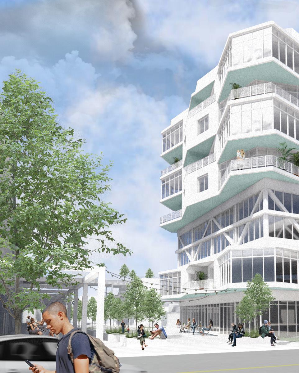
The city of Chicago is planning to develop an empty lot to provide affordable housing and retail for the neighborhood’s increasing displaced population. The site, located in Pilsen on Chicago’s Lower West Side, sits to the south of the active Metra rail lines and adjacent to the city’s newest “rails-to-trails” initiative, the Paseo Trail. To the west of the site is Pilsen’s existing commercial corridor lined with local restaurants and small businesses. The city aims to test various densities of planning, requiring a 50% parking ratio and at least 25% open space. It will be zoned as RM-6 and treated as a planned development (PD).

6 Integrative Design Studio - Chicago - Spring 2022

7
/
Samantha Druhot
Jack Flaherty
HISTORY
PILSEN, CHICAGO
In 1910, on the corner of 18th Street and Halstead, a Pilsen resident walked out of the garment factory she worked in, protesting poor working conditions and unfair wages. Her call for change echoed throughout Chicago, sparking the Garment Worker’s Strike of 1910. This led to the formation of the largest clothing workers unions in the country. The strength and courage to advocate for herself and her community is a common trait seen in Pilsen residents throughout history and in present day.


project site
garment factories/warehouses, c. 1910 rail service, c. 1910
8 Integrative Design Studio - Chicago - Spring 2022
9 Samantha Druhot / Jack Flaherty
URBAN FABRIC

City Neighborhood

10 Integrative Design Studio - Chicago - Spring 2022
Neighborhood Site


11 Samantha Druhot / Jack Flaherty
THE WEAVE CONCEPT TO SITE
The first step in the garment making process is the procurement of the fabric. The power loom became the key invention for this manufacturing process, using various dynamic components to achieve a woven fabric.

Diagramming the motions of a loom develops several ideas of direction and movement. An idea of two things sliding past each other to allow something else to move through it is translated into urban scale moves on the site.
Vehicle Circulation: Weaving in the existing urban fabric to create logical street circulation and service space for parking and alleyways.

12 Integrative Design Studio - Chicago - Spring 2022
Power Loom
The heddles of the loom move past each other vertically, separating threads of the warp, allowing the shuttle to weave the threads of the weft.

Weave
Several dynamic elements make up the machine, placing a focus on layering directions of movement.
13 Samantha Druhot / Jack Flaherty
THE ASSEMBLY CONCEPT TO SITE
The factory process for garment manufacturing was perfected during the second industrial revolution. A need for efficiency bred simplified strategies in the floor plan arrangements of input and output.


When examining the factory process, it becomes clear that the human action happens in relation to the common resource. The site can then be oriented to achieve a similar understanding of space, order, and program.
Residential Programming: Assembling the residences on the site in the same manner as the factory: blocks of living spaces oriented around community spaces, like amenities in the lobby of the apartment building.
14 Integrative Design Studio - Chicago - Spring 2022
Organization
The layout of these facilities separated workers into cutting and sewing teams for streamlined production.

Assemble
Cutting teams move cut fabric patterns to a central communal table for the sewing teams to gather and reassemble.
WORK STATION WORK STATION WORK STATION WORK STATION WORK STATION WORK STATION WORK STATION WORK STATION WORK STATION WORK STATION WORK STATION WORK STATION P A R T S DISTRIBUTION INPUT OUTPUT P A R T S DISTRIBUTION WORK STATION WORK STATION WORK STATION WORK STATION WORK STATION WORK STATION P A R T S DISTRIBUTION SEWING TEAM SEWING TEAM WORK STATION WORK STATION WORK STATION WORK STATION WORK STATION WORK STATION SEWING TEAM SEWING TEAM SEWING TEAM SEWING TEAM SEWING TEAM INPUT OUTPUT INPUT OUTPUT
15 Samantha Druhot / Jack Flaherty
THE STITCH CONCEPT TO SITE

Cutting teams take rolls of the woven fabric and cut patterns from the whole. These patterns designed for the contours of the body are then passed through the factory production line to be sewn back together.

Once the cut patterns reach the sewing teams, they are re-assembled to be joined together by various types of stitches. The act of the stitch is repetitive and layered, allowing for creations of new and richer wholes.
Pedestrian
Circulation: Stitching all sides of the site back together with pedestrian walkways that run adjacent to restaurants and retail and connect back to the shared street along the major outdoor space at the Paseo Trail.
16 Integrative Design Studio - Chicago - Spring 2022
Pattern Cutting and Sewing
Cutting teams cut geometries called patterns from sheets of fabric and pass along to be sewn back together.

Stitch
Various stitch patterns are used to reattach patterns and create new wholes.
17 Samantha Druhot / Jack Flaherty
PLANNING AND PROGRAM
SITE SEQUENCE
CONCEPT TO SITE
Following the same sequence fabric travels through to become a finished garment, the site must experience each step in the process.
Examining a woven fabric informs proportions, scales, and layers within the newly formed site. These layers occur as broadly as city street grids and as personally as sidewalks and entry pathways.

 Garment Workers’ Mural on Paseo Trail
20 Integrative Design Studio - Chicago - Spring 2022


Establish Urban Fabric Distribute Residences Weave Community Spaces Stitch Walking Paths 21 Samantha Druhot / Jack Flaherty
SITE PLAN CONCEPT
The existing city street grids reestablishes itself on the empty lot, weaving the urban fabric of Chicago back together.

The residences are then distributed orienting themselves around the retail center of the site and the community space housed in the apartment building lobby.
The residences are then woven together using indoor and outdoor community bridges.
Features of the site plan include a continuation of 18th Street’s commercial corridor on the new Peoria Street; a shared street to the west, adjacent to the Paseo Trail, promoting walk-ability and engagement with the outdoors; additional pedestrian paths connecting the edges of the site back to the Paseo Trail.
key restaurant/cafe retail community center day care bike shop lobby/lounge loading dock playground basketball court
9 1 2 3 4 5 6 7 8 9
8
22 Integrative Design Studio - Chicago - Spring 2022

1 1 1 1 1 2 2 5 4 3 6 6 7 7 8 8 23 Samantha Druhot / Jack Flaherty
ROOF PLAN CONCEPT
The enhancement of this historic community continues as residences are distributed above ground floor retail and around communal areas. A series of elevated indoor and outdoor bridges act as community and amenity spaces, weaving residences together again.

The outdoor bridges are accessible by exterior staircases and weave over smaller housing typologies. The public is able to explore seating areas, pergola covered grilling stations, and communal garden spaces.
The apartment building is woven together with two interior bridges that span over Peoria Street. These spaces hold amenities like a sewing education center, fitness gym and yoga studio, and community kitchens.
1 2 3 4 5 6 key
5 4
roof terrace elevated garden shade pergola green roof pv arrays mechanical space
24 Integrative Design Studio - Chicago - Spring 2022

1 2 2 5 4 3 6 6 2 3 3 3 2 5 5 5 1 4 1 4 5 6 25 Samantha Druhot / Jack Flaherty

26 Integrative Design Studio - Chicago - Spring 2022

27
/
Samantha Druhot
Jack Flaherty
PROGRAM
KEY
residences restaurants/retail community spaces/amenities lobby utility/back of house parking


Ground Floor Residences
unit matrix studio 56 1 bedroom 120 2 bedroom 105 3 bedroom 109 total 390
parking matrix street spaces 46 lot spaces 74 structure spaces 80 total 200 28 Integrative Design Studio - Chicago - Spring 2022
Community Bridges open space matrix paseo trail 56 corner park 120 pedestrian paths 105 community bridges 109 total % 390


29 Samantha Druhot / Jack Flaherty
PROGRAM
SUSTAINABILITY AND WELLNESS
Retention Pond
This pond collects and consolidates water during heavy rainfall. It also creates a wellness destination for the community.
Permeable Pavers
Made of a porous concrete or stone, water can slowly penetrate the surfaces leading to better drainage and filtered runoff.
Bioswales
These vegetated storm water management systems maintain a walkable, green street-scape while treating and filtering water.
Roof Gardens
Wellness is increased through vegetated and well circulated green spaces. Some in which are elevated for better views.
Waste Management
Waste is consolidated with convenient trash chutes that use a vacuum system to transfer trash to the service center to be processed.
Solar Panels

Throughout the site there are more than 1,200 panels producing a total of 360 KW. This is the optimal amount for a site this large.
Service Center
The service center stores excess energy and rain water. It also services the retention pond, maintaining its water level.
30 Integrative Design Studio - Chicago - Spring 2022

31 Samantha Druhot / Jack Flaherty
BUILDING AND DEVELOPMENT
BUILDING
CONCEPT TO FORM
Referring back to motions of the power loom, the apartment building is formed reflecting different components of the machine.
The main bar buildings shift past each other like heddles of a loom, the difference in height representing the vertical displacement of the threads of the warp.
The community bridges weave over and through the bar buildings in the perpendicular direction, achieving the weft of the woven fabric.
Loom Weave Motion
34 Integrative Design Studio - Chicago - Spring 2022
RESIDENTIAL RESIDENTIAL COMMUNITY + COMMUNITY 35 Samantha Druhot / Jack Flaherty
36 Integrative Design Studio - Chicago - Spring 2022

37
Samantha Druhot / Jack Flaherty
FLOOR PLANS
1ST AND 2ND
The ground level and 2nd floor of the apartment building sit on either side of Peoria Street. Entrances are easily noted underneath the above community bridges.
A restaurant and bar fills the street-front along 18th Street while a cafe at the southern end of the west bar building’s lobby connects the building to the pedestrian path.

38 Integrative Design Studio - Chicago - Spring 2022
Ground Floor Plan
2nd Floor Plan
39 Samantha Druhot / Jack Flaherty
FLOOR PLANS

3RD AND 4TH
The first community bridge connects both apartment bars at the 3rd floor with a community kitchen and public workspaces at either end and the sewing education center in the space spanning over the street.
The 4th floor allows a double height space in the main community areas. However the floor plate of the apartment continues through the bridge space, allowing one to weave over or through the amenity space.
40 Integrative Design Studio - Chicago - Spring 2022
3rd Floor Plan
4th Floor Plan
41 Samantha Druhot / Jack Flaherty
FLOOR PLANS
5TH AND 6TH
The second community bridge connects continuously at the 5th floor with smaller breakout spaces at the 6th floor overlooking the active double height spaces.
Where the bridges weave into the apartment building, a change in program and articulation occurs. Studio apartments infill spaces with floor-toceiling glass windows, again calling to the warp and weft patterns of weaving.

42 Integrative Design Studio - Chicago - Spring 2022
5th Floor Plan
6th Floor Plan
43 Samantha Druhot / Jack Flaherty
FLOOR PLANS
7TH AND 8TH
The 7th and 8th floors are uninterrupted by bridges weaving through and maintain the stitch pattern of the 1 bedroom units and 2 bedroom corner units.

44 Integrative Design Studio - Chicago - Spring 2022
7th Floor Plan
8th Floor Plan
45 Samantha Druhot / Jack Flaherty
UNITS
CONCEPT TO FORM
Recalling the repetitive over-under motion of stitch patterns, the facade of the apartment building layers to reflect this step of the garment making process.
Two unit types are developed from this stitch pattern, integrating the balcony into the peak or valley of the form.

Stitch Layer
Stack
UnitTypeB UnitTypeA UnitTypeB UnitTypeA
46 Integrative Design Studio - Chicago - Spring 2022
UnitTypeA
UnitTypeB

47 Samantha Druhot / Jack Flaherty
UNIT PLAN
TYPICAL STUDIO
Window walls in the studio units allow daylight to reach as much of the floor area as possible.

Studio units are organized with a wet wall to allow for the mechanical and plumbing equipment to be vertically continuous when the floor plan changes to a one-bedroom above or below.
Studio - 440 sf

48 Integrative Design Studio - Chicago - Spring 2022

49 Samantha Druhot / Jack Flaherty
Studio Apartment: A window wall washes the kitchen and living space with daylight while the bed area is pulled further into the unit, giving it some privacy.
UNIT PLAN
1 BEDROOM
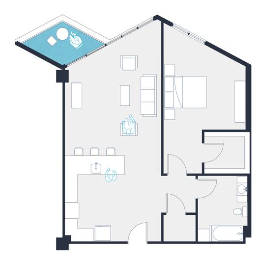

Two one bedroom unit types exist in either a peak or a valley to create the undulating stitch of the facade.
Living spaces have window walls that open onto a private balcony. Bedrooms have punched window openings in a solid wall to provide privacy from the balcony.
Unit (B) - 890 sf
Unit (A) - 900 sf
50 Integrative Design Studio - Chicago - Spring 2022

51 Samantha Druhot / Jack Flaherty
One-Bedroom Apartment: A U-shaped kitchen opens to the living area, granting views and daylight to both gathering spaces.
UNIT PLAN
2 BEDROOM

Two types of two bedroom units exist at the corners of the building, providing either a large extending corner living space or a private corner balcony.

Bedrooms at either exterior wall follow the same rule with punched openings, while the living spaces maintain window walls for light and air.
Unit (B) - 1,250 sf
Unit (A) - 1,220 sf
52 Integrative Design Studio - Chicago - Spring 2022
53 Samantha Druhot / Jack Flaherty
Two-Bedroom Apartment: The corner living room and kitchen are surrounded with daylight, opening onto a balcony with panoramic views.
ELEVATION
WEST
Recalling the motions of the loom and dynamics of a weave, the stitch pattern of the elevation is broken up by horizontal bands of glass where the bridges meet the building.
A vertical weave is achieved with alternating fenestration patterns that indicate the program of the spaces behind it.

54 Integrative Design Studio - Chicago - Spring 2022

55
Samantha Druhot / Jack Flaherty
COMMUNITY BRIDGES
AMENITIES
Community bridges weave into the building at the 3rd, 4th, 5th, and 6th floors.
The 3rd/4th floor bridge provides more public amenities that can be accessed by the public from the elevator lobby at the ground floor.
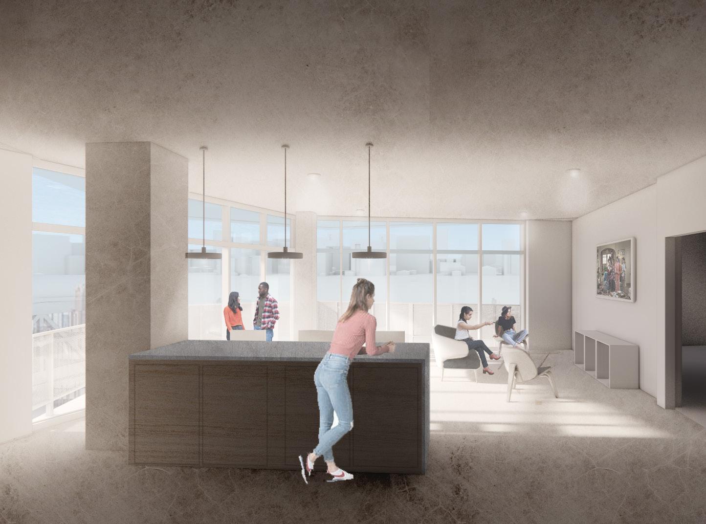
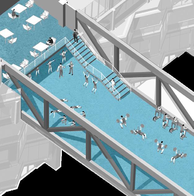
The 5th/6th floor bridge provides amenities private to the residents of the building. Fitness areas span over the street, placing active spaces on display as visual connections to the community from the ground.


On Site Amenities
• Community Center (1st Floor)
• Cafe (1st Floor)
• Lounges (1st, 4th, and 6th Floors)
• Reserved Work Spaces (3rd Floor)
• Sewing Education Center (3rd Floor)
• Community Breakfast Bar (3rd Floor)
• Yoga Studio (5th Floor)
• Fitness Center (5th Floor)
• Community Kitchen (5th Floor)
• Rooftop Patio and Grill Areas (5th Floor)
Breakout Space Fitness Center
56 Integrative Design Studio - Chicago - Spring 2022
Community Kitchen
57 Samantha Druhot / Jack Flaherty
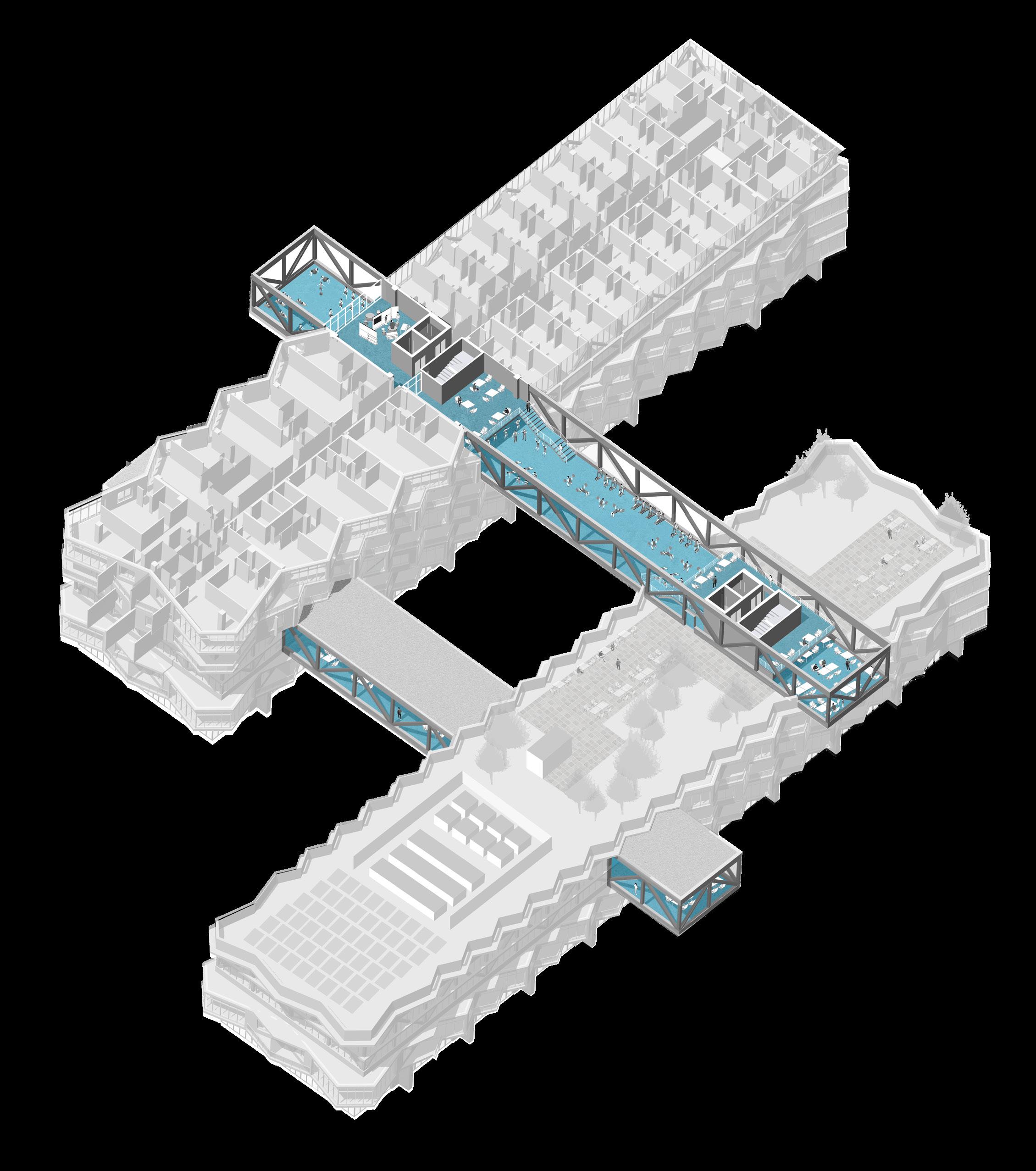
BUILDING SECTION
THROUGH BRIDGES
Highlighting the activity spaces and human moments, the community bridge connects the east and west apartment buildings with a fitness area spanning over Peoria Street.
1 2 3 5 6 8 6 58 Integrative Design Studio - Chicago - Spring 2022
7 1
1
8
lobby mechanical/service fitness center yoga studio community kitchen seating area pv array green roof 4
roof (+ 84’-0”)
8th floor (+ 74’-0”)
7th floor (+ 64’-0”)
5th floor (+ 44’-0”)
3rd floor (+ 24’-0”)
2nd floor (+ 14’-0”) ground floor (+ 0’-0”)
2 3 4 5 6 7
2 6 6
20’ 40’ 59 Samantha Druhot / Jack Flaherty
0 10’

60 Integrative Design Studio - Chicago - Spring 2022

61 Samantha
/
Druhot
Jack Flaherty
ASSEMBLIES AND DETAILS
WALL SECTIONS
3 TYPES
The wall sections cut through balconies to examine the conditions created by the undulating floor plans.
Three major conditions arise when the community bridge weaves into the building:
1. A section through the lobby and typical units above, uninterrupted
2. A section through the lobby and typical units above, interrupted by the steel truss bridge at the indicated floors
3. A section through the lobby and typical units above, interrupted by a curtain wall at the studio apartment units
BALCONY WALL SECTION 1” = 1’-0”
PUNCHED WINDOW OPENING
PRE-CAST CONCRETE WALL ASSEMBLY
CONCRETE FLOOR SLAB
WINDOW WALL BEYOND PRE-CAST CONCRETE WALL ASSEMBLY
BALCONY DRAIN TO INT. CHASE
CONCRETE FLOOR SLAB
PRE-CAST CONCRETE WALL ASSEMBLY
PUNCHED WINDOW OPENING
2’ 1’ 4’ 0
64 Integrative Design Studio - Chicago - Spring 2022
1 2 3
TOP OF BALCONY
3” = 1’-0”
DETAIL
WINDOW SILL
5/8” INT. GYP. BOARD
5 5/8“ MTL. STUD WALL W/ BATT ROLL INSUL. 5/8“ EXT. GYP. BOARD PERMEABLE MEMBRANE
2” RIGID INSULATION AIR SPACE
CONCRETE FLOOR SLAB EMBED. STL. ANGLE EMBED. STL. PLATE
4” EXTERIOR PRE-CAST CONCRETE PANEL
SOFFIT ASSEMBLY MTL. FLASHING
BOTTOM OF BALCONY DETAIL
3” = 1’-0”
GUARD RAIL BASE ASSEMBLY BALCONY PAVERS
2” RIGID INSULATION
CONCRETE FLOOR SLAB EMBED. STL. ANGLE EMBED. STL. PLATE
1” AIR SPACE
3” RIGID INSULATION
PERMEABLE MEMBRANE
5/8” EXT. GYP. BOARD
5 5/8” MTL. STUD WALL W/ BATT ROLL INSULATION
5/8” INT. GYP. BOARD WINDOW HEAD
1 2 3
65 Samantha Druhot / Jack Flaherty
DEEP DIVE CONCEPT TO DETAIL
BALCONY DRAIN TO INT. CHASE
The floor plan of the apartment building follows a stitch pattern. This conceptually relates units to each other both vertically and horizontally.

The repetition of the over/under stitch pattern creates positive and negative spaces for integrated balconies.
CONCRETE FLOOR SLAB
PRE-CAST CONCRETE WALL ASSEMBLY
The multi-directional motions of the wall section are explored further in the detailing of the balcony connections.
PUNCHED WINDOW OPENING BALCONY WALL SECTION 1” = 1’-0”
PUNCHED WINDOW OPENING PRE-CAST CONCRETE WALL ASSEMBLY
CONCRETE FLOOR SLAB
Stitch Layer Vertical
WINDOW WALL BEYOND PRE-CAST CONCRETE WALL ASSEMBLY
66 Integrative Design Studio -
- Spring 2022
Chicago
BOTTOM OF BALCONY DETAIL
3” = 1’-0”
GUARD RAIL BASE ASSEMBLY BALCONY PAVERS
2” RIGID INSULATION
CONCRETE FLOOR SLAB
EMBED. STL. ANGLE EMBED. STL. PLATE
1” AIR SPACE
3” RIGID INSULATION
PERMEABLE MEMBRANE
5/8” EXT. GYP. BOARD
5 5/8” MTL. STUD WALL W/ BATT ROLL INSULATION
5/8” INT. GYP. BOARD WINDOW HEAD
TOP OF BALCONY DETAIL
WINDOW SILL
5/8” INT. GYP. BOARD
5 5/8“ MTL. STUD WALL W/ BATT ROLL INSUL. 5/8“ EXT. GYP. BOARD PERMEABLE MEMBRANE
2” RIGID INSULATION
AIR SPACE
CONCRETE FLOOR SLAB
EMBED. STL. ANGLE EMBED. STL. PLATE
4” EXTERIOR PRE-CAST CONCRETE PANEL SOFFIT ASSEMBLY MTL. FLASHING
3” = 1’-0” BOTTOM OF BALCONY DETAIL
67 Samantha Druhot / Jack Flaherty
FOUNDATION PLAN
Column and Caisson Shear Walls
Notes
• System: Concrete Columns and Slab
• Typ. Grid: 25’-0” x 30’-0”
• # of Stories: 8 (caissons required)
INTEGRATED 30’ 30’ 30’ 12’ 8’ 8’ 25’ 30’ 8’
68 Integrative Design Studio - Chicago - Spring 2022
69 Samantha Druhot / Jack Flaherty
STRUCTURAL PLAN
Column Shear Walls Notes
• System: Concrete Columns
• Floor: Post-Tensioned Slab
• Min. Slab Thickness: 8”
• Max. Span: 30’-0”
• Max. Cantilever: 8’-0”
W/D W/D W/D W/D W/D W/D E.C. TRASH W/D W/D W/D W/D
INTEGRATED 30’ 30’ 30’ 12’ 8’ 8’ 25’ 30’ 8’
70 Integrative Design Studio - Chicago - Spring 2022
W/D W/D W/D W/D W/D W/D W/D W/D W/D W/D E.C. TRASH W/D W/D W/D W/D W/D W/D E.C.
W/D W/D 71 Samantha Druhot / Jack Flaherty
TRASH
W/D W/D W/D W/D W/D W/D E.C. TRASH W/D W/D W/D W/D W/D W/D E.C. TRASH W/D W/D W/D W/D W/D W/D W/D W/D W/D W/D W/D E.C. W/D W/D W/D W/D
PLAN INTEGRATED Heat Pump Supply Shaft Return Shaft Intake Outtake
• Make-up air shafts
corridor • Heat pumps placed
accommodate inverting unit
72 Integrative Design Studio - Chicago - Spring 2022
MECHANICAL
Notes
at ends of
to
plans from floor to floor
W/D W/D W/D W/D W/D W/D W/D W/D W/D W/D E.C. TRASH W/D W/D W/D W/D W/D W/D E.C.
W/D W/D 73 Samantha Druhot / Jack Flaherty
TRASH
W/D W/D W/D W/D W/D W/D E.C. TRASH W/D W/D W/D W/D W/D W/D W/D W/D W/D W/D E.C. TRASH W/D W/D W/D W/D S S SS S S GFI GFI GFI GFI GFI GFI GFI S GFI GFI GFI GFI GFI GFI S S GFI GFI GFI GFI GFI GFI GFI GFI GFI GFI S GFI GFI GFI GFI GFI S S SS S S GFI GFI GFI GFI GFI GFI S GFI GFI GFI GFI S GFI GFI GFI GFI GFI GFI GFI GFI GFI GFI GFI S S GFI S S GFI S S S S S S S S S S GFI GFI GFI GFI GFI GFI S S GFI GFI GFI GFI GFI S S S S S S S S S GFI S GFI GFI GFI S S S S S S S S S GFI S S S S S GFI GFI S S S S S S S S S S GFI GFI GFI GFI GFI S S S S S S S S S GFI GFI GFI GFI S S S GFI S S S S S GFI GFI S S S S S S S S S S GFI GFI GFI GFI GFI S S S S S S S S S GFI GFI GFI GFI S S S S S S S S S S S S GFI GFI GFI GFI S S S S S GFI GFI GFI S S S S S GFI GFI S S S S S S S S S S GFI GFI GFI GFI GFI S S S S S S S S S GFI GFI GFI GFI S W/D W/D W/D W/D W/D W/D E.C. TRASH W/D W/D W/D W/D W/D W/D W/D W/D GFI S S GFI GFI GFI GFI GFI GFI GFI GFI GFI GFI S GFI GFI GFI GFI GFI GFI GFI GFI GFI GFI GFI GFI GFI GFI S GFI GFI GFI GFI S S S GFI GFI GFI GFI GFI S S GFI GFI GFI GFI GFI GFI GFI GFI GFI GFI GFI GFI GFI GFI GFI S S GFI GFI GFI GFI GFI GFI GFI GFI GFI S GFI GFI GFI GFI S S GFI GFI GFI GFI GFI ELECTRICAL PLAN INTEGRATED Outlet GFI Outlet Switch Recessed Can Light Wall Mounted Light Electrical Panel
• Max. Distance from corner: 4’-0” • Max. Distance b/w outlets: 12’-0” 74 Integrative Design Studio - Chicago - Spring 2022
Notes
W/D W/D W/D W/D W/D W/D W/D W/D W/D W/D E.C. TRASH W/D W/D W/D W/D W/D W/D W/D W/D W/D W/D E.C. TRASH S GFI GFI GFI GFI GFI S GFI GFI GFI GFI GFI GFI S GFI GFI GFI GFI GFI GFI S GFI GFI GFI GFI GFI GFI S GFI GFI GFI GFI GFI GFI GFI S S S GFI GFI GFI GFI GFI GFI S S GFI GFI GFI GFI GFI GFI S S SS S S S SS S GFI GFI GFI GFI GFI GFI GFI GFI GFI GFI GFI GFI S W/D W/D W/D W/D W/D W/D E.C. TRASH W/D W/D S S S GFI GFI S S GFI GFI S S S S S S S GFI GFI S S S S S S S S S S GFI GFI GFI GFI GFI GFI S S S S S GFI GFI GFI GFI GFI S S S S S S S S S GFI GFI GFI GFI S 75 Samantha Druhot / Jack Flaherty
PLUMBING PLAN
INTEGRATED
Waste Pipe Hot - Cold - Vent Riser
Notes
• Waste Pipe dia. : 6”
• Typical Riser Pipe dia. : 4”
• Min. Wall thickness: 8”
W/D W/D W/D W/D W/D W/D E.C. TRASH W/D W/D W/D W/D
76 Integrative Design Studio - Chicago - Spring 2022
W/D W/D W/D W/D W/D W/D W/D W/D W/D W/D E.C. TRASH W/D W/D W/D W/D W/D W/D E.C.
W/D W/D 77 Samantha Druhot / Jack Flaherty
TRASH
FIRE PROTECTION PLAN INTEGRATED
Notes
• Max. Distance b/w sprinklers: 12’-0” • Min. Slope of sprinkler line: 1/8” per 1’-0”
W/D W/D W/D W/D W/D W/D E.C. TRASH W/D W/D W/D W/D W/D W/D W/D W/D W/D W/D E.C. TRASH W/D W/D W/D W/D
Ceiling
Standpipe
Wall Mounted Sprinkler
Mounted Sprinkler
78 Integrative Design Studio - Chicago - Spring 2022
W/D W/D W/D W/D W/D W/D W/D W/D W/D W/D E.C. TRASH W/D W/D W/D W/D W/D W/D W/D W/D W/D W/D E.C. TRASH W/D W/D W/D W/D W/D W/D E.C. TRASH W/D W/D 79 Samantha Druhot / Jack Flaherty
LIFE SAFETY AND EGRESS PLAN INTEGRATED
Travel Path
2 Hour Rated Wall
1 Hour Rated Wall
Notes
• Max. Travel Distance: 150’-0”
• Max. Dead-End Corridor: 50’-0”
• 2 HR fire rating at stairs and shafts
• 1 HR fire rating at corridor and b/w units
• Occupant Load: - Floor Area: 23,180 SF
- Factor: 125 SF / Occupant
- Total Floor Occupant Load: 186 people
Travel Distance: 77’ - 2”
Stair #1: Width: 44” (2 widths) Capacity: 60 people/width Egress: 120 people
Travel Distance: 68’ - 2”
Travel Distance: 100’ - 0”
Stair #2: Width: 44” (2 Capacity: 60 Egress: 120 people
W/D W/D W/D W/D W/D W/D E.C. TRASH W/D W/D W/D W/D W/D W/D W/D W/D W/D W/D E.C. TRASH W/D W/D W/D W/D
80 Integrative Design Studio - Chicago - Spring 2022
Travel Distance: 131’ - 7”
Travel Distance: 105’ - 3”
Travel Distance: 54’ - 5” widths) people/width people
Stair #3: Width: 44” (2 widths) Capacity: 60 people/width Egress: 120 people
W/D W/D W/D W/D W/D W/D W/D W/D W/D W/D E.C. TRASH W/D W/D W/D W/D W/D W/D W/D W/D W/D W/D E.C. TRASH W/D W/D W/D W/D W/D W/D E.C.
W/D W/D
TRASH
81 Samantha Druhot / Jack Flaherty
ADA ACCESSIBLE UNIT
INTEGRATED
Living Room
• 60” turning radius
• Clear of furniture and walls
Kitchen
• 30” x 48” clear spaces for parallel or front approach to all appliances
• Knee and toe clear space at workspace
• Knee and toe clear space at sink
Laundry
• 30” x 48” clear space for front approach to either appliance
Bedroom
• Typical “T” turn (60” x 60”)
• Parallel and front approach to bed
Closet
• 60” turning radius
• 18” clear for pull/push of door
Bathroom
• Toilet center line 18” from wall
• Grab bars at toilet
• 18” clear for pull/push of door
• 60” turning radius
• 30” parallel approach to shower
• No step shower entry
• 18” deep shower seat
• 18” clear for pull/push of door
82 Integrative Design Studio - Chicago - Spring 2022
83 Samantha Druhot / Jack Flaherty
CODE MATRIX
INTEGRATED
CODES USED
Zoning Ordinance: City of Chicago Zoning Ordinance 2016 Building Codes: Chicago Building Code Title 14B 2019 Chicago Building Rehabilitation Code Title 14R 2019
Energy Code Chicago Energy Conservation Code Title 14N 2019 Accessibility Code: Chicago Building Code 14B-11 2019 ANSI 117.1 2009 Capital Development Board Illinois Accessibility Code 2018 Federal ADA Standards for Accessible Design 2010
ZONING ISSUE CHAPTER/ARTICLE
1.01 Zoning District a) Use of Property 17-02-0104 RM
1.02 Landmark Building /District 1.03 Lakefront Protection District
1.04 Zoning Overlay PD 1614
1.05 Pedestrian Street
1.06 Minimum Lot Area 17-02-0301 Min. Lot Area Per Unit 17-02-303-A
1.07 Maximum Floor Area Ratio 17-02-304-A
1.08 Total Building Area 1.09 Building Height & Limitations 17-02-311-A a) Exception to Height Limits 17-13-0600
1.10 Setbacks
a) Minimum Front Setback 17-02-0305-B b) Other Setbacks 17-02-0309-A d) Allowed Projections
1.11 On-Site Open Space 17-02-0308 PD 1614
1.12 Number of Dwelling Units PD 1614
1.13 Off Street Parking PD 1614 a) ADA Parking Spaces IAC 208
1.14 Bicycle Parking 17-10-0208
1.15 Off Street Loading 17-10-1100
1.16 Landscaping 17-10-1101-B
BUILDING CODE ISSUE
CHAPTER/ARTICLE
Chapter 3 Classification by Occupancy 14B-3-303 a) X Use Occupancy 14B-5-508
Chapter 10 Occupant load 14B-10-1004 Table 1004.5
Chapter 5 Building Height and Number of Stories 14B-5-504
a) Occupiable Rooftops
14B-5-503.1.4 b) Height in Feet 14B-5-504.3
c) Number of Stories
14B-5-504.4 d) Mixed Use and Occupance Height 14B-5-508.2.2
Mezzanine Height and Area 14B-5-505.2 Building Area
14B-506.2 Table 506.2
a) Sprinkler System 14R-9-903.3.1 b) Mixed Use and Occupancy Area 14R-5-508.2.3
Chapter
Type 84 Integrative Design Studio - Chicago - Spring 2022
6 Classification by Construction
REQUIREMENT
ACTUAL N/A SHEET
RM6 RM6 Multi-Unit Residential Multi-Family No - X No - X PD 1614 PD 1614 No - X 1,650 SF 316,000 SF 300 SF 810 SF 4.4 (FA of all buildings / net site area) 1.35 Varies 512,223 SF None 84' PD 161415' or 12% Lot Depth (Whichever is less) 10'-4" (12% of 86') Side Setbacks - 10% of lots width, Townhouses are 10' 4'-6" (10% of 45') Balconies and minor building projections - X 36 SF per dwelling unit 251 SF per unit 25% gross site area, minimum 31% Varies 390 100 spots 200 5 for every 100 parking spaces 10 Minimum 2-50 - X 1 per 200,000 SF of Floor Area, (Loading spot is 10'x25') 3 1 parkway tree for every 25' of street front -
REQUIREMENT
ACTUAL N/A SHEET
RM-6 RM-6
Multi Family Residential Multi Family Res. 1004.5 R=125 gross, 20 net 2,264
Type 1A Construction: Unlimited 84' (8 stories) not included in building area compliant Unlimited 84' Unlimited 8 with main occupancy accordingly compliant - X Unlimited 512,223 SF Automatic Sprinkler System Automatic Unlimited
X 85 Samantha Druhot / Jack Flaherty
CODE MATRIX
INTEGRATED
a) Minimum Front Setback 17-02-0305-B b) Other Setbacks 17-02-0309-A
d) Allowed Projections
1.11 On-Site Open Space 17-02-0308 PD 1614
1.12 Number of Dwelling Units PD 1614
1.13 Off Street Parking PD 1614 a) ADA Parking Spaces IAC 208
1.14 Bicycle Parking 17-10-0208 1.15 Off Street Loading 17-10-1100 1.16 Landscaping 17-10-1101-B
BUILDING CODE ISSUE CHAPTER/ARTICLE
Chapter 3 Classification by Occupancy 14B-3-303 a) X Use Occupancy 14B-5-508 Chapter 10 Occupant load 14B-10-1004 Table 1004.5
Chapter 5 Building Height and Number of Stories 14B-5-504 a) Occupiable Rooftops 14B-5-503.1.4 b) Height in Feet 14B-5-504.3 c) Number of Stories 14B-5-504.4 d) Mixed Use and Occupance Height 14B-5-508.2.2 Mezzanine Height and Area 14B-5-505.2 Building Area 14B-506.2 Table 506.2 a) Sprinkler System 14R-9-903.3.1 b) Mixed Use and Occupancy Area 14R-5-508.2.3
Chapter 6 Classification by Construction Type a) Building X 14B-6-602.1 Separated Occupancies 14B-5-508.4 Table 508.4 Fire-Resistive Rating Requirements 14B-6-601 Table 601 a) Primary Structural Frame e) Roof Support 14B-6-601(a) (b) b) Exterior Bearing Walls 14B-6-601 Fire separation distance 14B-6-602 Exterior Structural Members 14B-6-601 (f) c) Interior Bearing Walls 14B-6-601 d) Exterior Non-bearing Walls 14B-6-601 d) Interior Non-bearing Walls 14B-6-601 e) Floor Construction and assoc. secondary members 14B-6-601 (g) e) Roof Construction and assoc. secondary members 14B-6-601 (b)(c)(h) Basement Construction 14B-6-605
Chapter 7 Fire Resistive Requirements
Exterior Structural Members 14B-7-704.10 Bottom Flange Protection 14B-7-704.11 Exterior Walls - Projections 14B-7-705.2 Max Area of Exterior Wall Opening 14B-7-705.8
Parapets 14B-7-705.11
Vertical Openings 14B-7-712
Shaft Enclosures 14B-7-713.4
Chutes 14B-7-713.13
Elevator, Dubmwaiter and other Hoistways 14B-7-713.14
Opening Protectives 14B-7-716.1(2) Ducts and Air Transfer Penetrations 14B-7-717
Furnace Boiler / Incidental Use 14B-5-509 Corridor 14B-10-1020.1
Chapter 8 Interior Finishes
Interior Wall and Ceiling Finish 14B-8-803.13 Interior Floor Finish 14B-8-804.4
Chapter 9 Fire Protection Equipment a) Sprinkler System 14B-9-903.3.1
Chapter 12 Interior Enviroment
Natural Ventilation Required
14B-12-1202.5.1 a) Residential basements 14B-12-1202.5.1.3
1.10 Setbacks
86 Integrative Design Studio - Chicago - Spring 2022
15' or 12% Lot Depth (Whichever is less)
-
10'-4" (12% of 86')
Side Setbacks - 10% of lots width, Townhouses are 10' 4'-6" (10% of 45')
Balconies and minor building projections - X 36 SF per dwelling unit 251 SF per unit 25% gross site area, minimum 31% Varies 390 100 spots 200 5 for every 100 parking spaces 10 Minimum 2-50 - X 1 per 200,000 SF of Floor Area, (Loading spot is 10'x25') 3 1 parkway tree for every 25' of street front -
REQUIREMENT
ACTUAL N/A SHEET
RM-6 RM-6 Multi Family Residential Multi Family Res. 1004.5 R=125 gross, 20 net 2,264 Type 1A Construction: Unlimited 84' (8 stories) not included in building area compliant Unlimited 84' Unlimited 8 with main occupancy accordingly compliant - X Unlimited 512,223 SF Automatic Sprinkler System Automatic Unlimited X Type 1A Type 1A 1A 1A 3 HR 3HR 1.5 HR 1.5HR 3 HR x 10' - 30' = 1HR; +30' = 3 HR 3HR 3HR 3HR 3HR 3HR 0HR 0HR 0HR 0HR 2HR 2HR 1.5HR 1.5HR - X 3HR 3HR
>30', Sprinklered = No Limit Unlimited equal to supporting wall compliant - X 2HR 2HR 2HR 2HR 2HR 2HR 2HR 2HR 2HR 2HR 2HR 2HR 1HR 1HR Automatic Sprinkler System Automatic area of operable openings >/= 4% floor area of unit 8.23% of req. unit area - X
87 Samantha Druhot / Jack Flaherty
CODE MATRIX INTEGRATED
a) Primary Structural Frame
e) Roof Support
14B-6-601(a) (b)
b) Exterior Bearing Walls 14B-6-601
a) Minimum Front Setback 17-02-0305-B b) Other Setbacks 17-02-0309-A
Fire separation distance 14B-6-602
d) Allowed Projections
1.11 On-Site Open Space 17-02-0308 PD 1614
Exterior Structural Members 14B-6-601 (f) c) Interior Bearing Walls 14B-6-601
1.12 Number of Dwelling Units PD 1614
1.13 Off Street Parking PD 1614 a) ADA Parking Spaces IAC 208
1.14 Bicycle Parking 17-10-0208 1.15 Off Street Loading 17-10-1100 1.16 Landscaping 17-10-1101-B
d) Exterior Non-bearing Walls 14B-6-601 d) Interior Non-bearing Walls 14B-6-601 e) Floor Construction and assoc. secondary members 14B-6-601 (g) e) Roof Construction and assoc. secondary members 14B-6-601 (b)(c)(h) Basement Construction 14B-6-605
BUILDING CODE ISSUE
Chapter 7 Fire Resistive Requirements
CHAPTER/ARTICLE
Exterior Structural Members 14B-7-704.10
Chapter 3 Classification by Occupancy 14B-3-303 a) X Use Occupancy 14B-5-508 Chapter 10 Occupant load 14B-10-1004 Table 1004.5
Bottom Flange Protection 14B-7-704.11 Exterior Walls - Projections 14B-7-705.2
Max Area of Exterior Wall Opening 14B-7-705.8 Parapets 14B-7-705.11 Vertical Openings 14B-7-712 Shaft Enclosures 14B-7-713.4 Chutes 14B-7-713.13 Elevator, Dubmwaiter and other Hoistways 14B-7-713.14 Opening Protectives 14B-7-716.1(2) Ducts and Air Transfer Penetrations 14B-7-717 Furnace Boiler / Incidental Use 14B-5-509 Corridor 14B-10-1020.1
Chapter 5 Building Height and Number of Stories 14B-5-504 a) Occupiable Rooftops 14B-5-503.1.4 b) Height in Feet 14B-5-504.3 c) Number of Stories 14B-5-504.4 d) Mixed Use and Occupance Height 14B-5-508.2.2 Mezzanine Height and Area 14B-5-505.2 Building Area 14B-506.2 Table 506.2 a) Sprinkler System 14R-9-903.3.1 b) Mixed Use and Occupancy Area 14R-5-508.2.3
Chapter 8 Interior Finishes
Interior Wall and Ceiling Finish 14B-8-803.13 Interior Floor Finish 14B-8-804.4
Chapter 9 Fire Protection Equipment
a) Sprinkler System 14B-9-903.3.1 Chapter 12 Interior Enviroment
Natural Ventilation Required 14B-12-1202.5.1 a) Residential basements 14B-12-1202.5.1.3 b) Openings below grade 14B-12-1202.5.1.4 Natural Light Required 14B-12-1204.2.1 a) Residential basements 14B-12-1204.2.4 b) Openings below grade 14B-12-1204.2.6 Ceiling Height 14B-12-1207.2
EXITS ISSUE CHAPTER/ARTICLE
Chapter 10 Means of Egress
Chapter 6 Classification by Construction Type a) Building X 14B-6-602.1 Separated Occupancies 14B-5-508.4 Table 508.4 Fire-Resistive Rating Requirements 14B-6-601 Table 601 a) Primary Structural Frame e) Roof Support 14B-6-601(a) (b) b) Exterior Bearing Walls 14B-6-601 Fire separation distance 14B-6-602 Exterior Structural Members 14B-6-601 (f) c) Interior Bearing Walls 14B-6-601 d) Exterior Non-bearing Walls 14B-6-601 d) Interior Non-bearing Walls 14B-6-601 e) Floor Construction and assoc. secondary members 14B-6-601 (g) e) Roof Construction and assoc. secondary members 14B-6-601 (b)(c)(h) Basement Construction 14B-6-605
Chapter 7 Fire Resistive Requirements
Exterior Structural Members 14B-7-704.10 Bottom Flange Protection 14B-7-704.11
Minimum Number of Exits 14B-10-1006.2 Egress from Stories or Occupiable Rooftop 14B-10-1006.3 a) Single Exits Allowed 14B-10-1006.3.3 b) Outdoor Area Exits 14-10-1004.7 Travel Distance to Exits 14B-10-1017.2 Max Distance from End of Corridor 14B-10-1020.4
Minimum Width of Exits
Exterior Walls - Projections 14B-7-705.2 Max Area of Exterior Wall Opening 14B-7-705.8 Parapets 14B-7-705.11
a) Stairs
Vertical Openings 14B-7-712 Shaft Enclosures 14B-7-713.4 Chutes 14B-7-713.13
Elevator, Dubmwaiter and other Hoistways 14B-7-713.14
Opening Protectives 14B-7-716.1(2) Ducts and Air Transfer Penetrations 14B-7-717
Furnace Boiler / Incidental Use 14B-5-509 Corridor 14B-10-1020.1
14B-10-1005.3.1 14B-10-1011.2 b) Other Egress Components 14B-10-1005.3.2 c) Doors 14B-10-1010.1.1 Swing of Doors 14B-10-1010.1.2.1 Landing length at doors 14B-10-1010.1.6 Hardware 14B-10-1010.1.9 Revolving Doors 14B-10-1010.1.4.1
Chapter 8 Interior Finishes
Electrically Locked Egress 14B-10-1010.1.9.7
Panic Hardware Required 14B-10-1010.1.10
Stairways
Interior Wall and Ceiling Finish 14B-8-803.13 Interior Floor Finish 14B-8-804.4
Chapter 9 Fire Protection Equipment
a) Headroom
a) Sprinkler System 14B-9-903.3.1
14B-10-1011.3 b) Tread and Risers 14B-10-1011.5
Chapter 12 Interior Enviroment Natural Ventilation Required 14B-12-1202.5.1 a) Residential basements 14B-12-1202.5.1.3
c) Stairway Landings 14B-10-1011.6 b) Handrail location required 14B-10-1011.11 e) Stair to roof and elevator equipment 14B-10-1011.12
14B-10-1011.15
f) Ship's ladder
1.10 Setbacks
b)
below grade
Openings
14B-12-1202.5.1.4
88 Integrative Design Studio - Chicago - Spring 2022
3 HR 3HR
15' or 12% Lot Depth (Whichever is less) 10'-4" (12% of 86') Side Setbacks - 10% of lots width, Townhouses are 10' 4'-6" (10% of 45')
1.5 HR 1.5HR 3 HR x
Balconies and minor building projections - X 36 SF per dwelling unit 251 SF per unit 25% gross site area, minimum 31% Varies 390 100 spots 200 5 for every 100 parking spaces 10 Minimum 2-50 - X 1 per 200,000 SF of Floor Area, (Loading spot is 10'x25') 3 1 parkway tree for every 25' of street front -
REQUIREMENT
10' - 30' = 1HR; +30' = 3 HR 3HR 3HR 3HR 3HR 3HR 0HR 0HR 0HR 0HR 2HR 2HR 1.5HR 1.5HR - X 3HR 3HR
ACTUAL N/A SHEET
RM-6 RM-6
Multi Family Residential Multi Family Res. 1004.5 R=125 gross, 20 net 2,264
>30', Sprinklered = No Limit Unlimited equal to supporting wall compliant - X 2HR 2HR 2HR 2HR 2HR 2HR 2HR 2HR 2HR 2HR 2HR 2HR 1HR 1HR Automatic
area of operable openings >/= 4% floor area of unit 8.23% of req. unit area - X - X glazed area >/= 8% floor area of unit 23.67% of req. unit area - X - X
storage, mezzanine, etc.
habitable, 8'-0' corridor,
Type 1A Construction: Unlimited 84' (8 stories) not included in building area compliant Unlimited 84' Unlimited 8 with main occupancy accordingly compliant - X Unlimited 512,223 SF Automatic Sprinkler System Automatic Unlimited X Type 1A Type 1A 1A 1A 3 HR 3HR 1.5 HR 1.5HR 3 HR x 10' - 30' = 1HR; +30' = 3 HR 3HR 3HR 3HR 3HR 3HR 0HR 0HR 0HR 0HR 2HR 2HR 1.5HR 1.5HR - X 3HR 3HR
>30', Sprinklered = No Limit Unlimited equal to supporting wall compliant - X 2HR 2HR 2HR 2HR 2HR 2HR 2HR 2HR 2HR 2HR 2HR 2HR 1HR 1HR Automatic Sprinkler System Automatic area of operable openings >/= 4% floor area of unit 8.23% of req. unit area -
Egress Capacity Factor: 0.15 x occupant 339 32" 32" Swing in direction of egress compliant 44" 44"
Should be accessible without locks or keys and not include tight grasping, tight pinching, or twisting of the wrist to operate compliant - X - X on doors swinging in direction of egress compliant 7' clear (from nose of stair) 10' min. 4" max 7" riser, min 11" tread 6 3/4" riser, 11" tread equal to width of stair or 48", whichever is less 48" both sides of stairs more than 3 risers compliant yes compliant
Sprinkler System Automatic
7'-6" habitable space and corridors, 7'-0" bathrooms,
8'-6"
baths REQUIREMENT ACTUAL N/A SHEET 2 Exits 3 Exits 2 Exits 2 Exits - X 2 Exits 2 Exits 250' (sprinklered) Max. 131'-7" 50' 15'-0" 44" 44"
X 89 Samantha Druhot / Jack Flaherty
X
Interior Wall and Ceiling Finish 14B-8-803.13
Interior Floor Finish 14B-8-804.4
Chapter 9 Fire Protection Equipment
a) Sprinkler System
Chapter 12 Interior Enviroment
CODE MATRIX INTEGRATED
14B-9-903.3.1
14B-12-1202.5.1 a) Residential basements 14B-12-1202.5.1.3 b) Openings below grade 14B-12-1202.5.1.4
Natural Ventilation Required
Natural Light Required 14B-12-1204.2.1 a) Residential basements 14B-12-1204.2.4 b) Openings below grade 14B-12-1204.2.6 Ceiling Height 14B-12-1207.2
EXITS ISSUE CHAPTER/ARTICLE
Chapter 10 Means of Egress
Minimum Number of Exits
14B-10-1006.2 Egress from Stories or Occupiable Rooftop 14B-10-1006.3 a) Single Exits Allowed 14B-10-1006.3.3 b) Outdoor Area Exits 14-10-1004.7 Travel Distance to Exits 14B-10-1017.2 Max Distance from End of Corridor 14B-10-1020.4
Minimum Width of Exits
a) Stairs
14B-10-1005.3.1 14B-10-1011.2 b) Other Egress Components 14B-10-1005.3.2 c) Doors 14B-10-1010.1.1 Swing of Doors 14B-10-1010.1.2.1 Landing length at doors 14B-10-1010.1.6 Hardware 14B-10-1010.1.9 Revolving Doors
14B-10-1010.1.4.1 Electrically Locked Egress 14B-10-1010.1.9.7 Panic Hardware Required 14B-10-1010.1.10 Stairways
a) Headroom
14B-10-1011.3 b) Tread and Risers 14B-10-1011.5 c) Stairway Landings 14B-10-1011.6 b) Handrail location required 14B-10-1011.11 e) Stair to roof and elevator equipment 14B-10-1011.12 f) Ship's ladder 14B-10-1011.15 g) Ladders 14B-10-1011.16
Handrails
a) Height 14B-10-1014.2 b) Extensions 14B-10-1014.6 c) Projections 14B-10-1014.8 Guards a) Where required
14B-10-1015.2 b) Height 14B-10-1015.3 c) Openings (ball test) 14B-10-1015.4 d) Window Openings 14B-10-1015.8 Stairway Enclosures 14B-10-1019.2 Corridor Width 14B-10-1020.2 Signage 14B-10-1023.9 Exterior stair as means of egress 14B-10-1027.2
90 Integrative Design Studio - Chicago - Spring 2022
area of operable openings >/= 4% floor area of unit 8.23% of req. unit area - X - X glazed area >/= 8% floor area of unit 23.67% of req. unit area - X - X
7'-6" habitable space and corridors, 7'-0" bathrooms, storage, mezzanine, etc. 8'-6" habitable, 8'-0' corridor, baths
REQUIREMENT
ACTUAL N/A SHEET
2 Exits 3 Exits 2 Exits 2 Exits - X
2 Exits 2 Exits 250' (sprinklered) Max. 131'-7" 50' 15'-0" 44" 44"
Egress Capacity Factor: 0.15 x occupant 339 32" 32" Swing in direction of egress compliant 44" 44" Should be accessible without locks or keys and not include tight grasping, tight pinching, or twisting of the wrist to operate compliant - X - X on doors swinging in direction of egress compliant 7' clear (from nose of stair) 10' min. 4" max 7" riser, min 11" tread 6 3/4" riser, 11" tread equal to width of stair or 48", whichever is less 48" both sides of stairs more than 3 risers compliant yes compliant - X - X 34"-38" measured from nose of stair 36" extends sloping for length of one tread at bottom, then horizontal for min. 12", horizontal for min. 12" at top riser compliant required 1.5" between handrail and adjacent surface compliant along open sided walking surfaces compliant 42" 42" spaced to prevent passage of a 4" diameter sphere compliant prevent passge of 4" sphere at <36", 6" sphere at ,42" compliant exit stairways require 2HR fire rating enclosure compliant depends on occupancy 60" exit signage in corridors and amenities compliant allowed for levels <45' above grade compliant
Automatic
System Automatic
Sprinkler
91 Samantha Druhot / Jack Flaherty
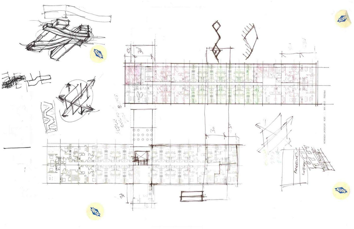
SKETCHES
PROCESS
SITE PLANNING AND CONTEXT

Left: Sketches exploring different weaving pattern, proportions, and scales on the site.
Right: Contextual perspective sketches depicting the experiential approach to the site from the surrounding neighborhood.


94 Integrative Design Studio - Chicago - Spring 2022


95 Samantha Druhot / Jack Flaherty
PROCESS
PROGRAMMING AND FORM
Left: Development of the site plan into 3 dimensional architecture, exploring different layers of the concept. Initial ground level programming thoughts.

Right: Building program beginnings showing unit types and community space integration.

96 Integrative Design Studio - Chicago - Spring 2022


97 Samantha Druhot / Jack Flaherty
PROCESS
ELEVATION AND EXPERIENCE
Left: Investigations of the conceptual applications in elevation, focus on bridge interaction and articulating fenestration.


Right: Preliminary perspective sketches depicting general massing and form.

98 Integrative Design Studio - Chicago - Spring 2022


99 Samantha Druhot / Jack Flaherty
PROCESS
ELEVATION AND EXPERIENCE
Left: Sketches looking to understand relationships between the form of the plan and the elevational consequences.

Right: Preliminary perspective sketches depicting general massing and form.

100 Integrative Design Studio - Chicago - Spring 2022
101 Samantha Druhot / Jack Flaherty
