
ii
C aring for S hip M odel S
Also by Rob Napier
Reconditioning an Eighteenth-Century Ship Model: ValkeniSSe, Retourschip of 1717
Legacy of a Ship Model: Examining HMS prinCeSS royal of 1773
Caring for S hip M odel S
A Narrative of Thought and Application
by Rob Napier

© 2022 by Rob Napier. All rights reserved.
No part of this book may be reproduced in any form without written permission from the publisher.
Published and Distributed by:
SeaWatch Books LLC
2040 Milburn Ave, Suite 102 #109 Maplewood, NJ 07040
web: www.seawatchbooks.com
e-mail: info@seawatchbooks.com
ISBN 979-8-9862370-0-8
Manufactured in the United States of America
First edition, first printing, 2022
This book was set in 11-point Adobe Caslon Pro.

Contents Case Study Roster vi Foreward by Grant Walker vii Part One: Prologue 3 Part Two: Perspectives on Ship Modeling 7 Focus on Compelling Impression: Blocks 10 Part Three: Practices and Applications 21 Focus on Dehydration 34 Part Four: Case Studies 57 Addendum 161 Epilogue 167 Acknowledgments 167 Notes 169 Sources 173 Index 181
Case Study Roster
vi
No. Vessel Name Vessel Type Date Page 1 Unidentified English fourth rate 1695 58 2 Valkenisse Dutch East Indiaman 1717 62 3 Princess Royal British second rate 1773 63 4 Warrior British third rate 1781 64 5 Constitution American frigate 1797 65 6 Unidentified French third rate about 1800 74 7 Unidentified French second rate about 1800 76 8 Andromeda British corvette 1810 81 9 Inez American merchant ship 1828 83 10 Yorkshire American packet ship 1843 86 11 Unidentified British steamship about 1865 90 12 Dunderberg American ironclad 1865 93 13 Unidentified American Down Easter about 1870 100 14 Belle American schooner yacht 1870 109 15 Panay American Down Easter 1877 110 16 Enterprise American cutter yacht 1878 114 17 Tioga American schooner yacht 1881 116 18 Corona American schooner yacht 1893 118 19 Roxana American houseboat yacht 1903 120 20 Doctor Saboia British hopper barge 1907 123 21 Unidentified American schooner yacht about 1910 124 22 Elena American schooner yacht 1911 127 23 Arizona American battleship 1916 136 24 Roseden British tramp 1918 137 25 Curacoa British light cruiser 1918 138 26 Helen Barnet Gring American merchant schooner 1919 148 27 Royal Scot British steamer 1930 149 28 Yare American sloop yacht 1936 150 29 Ocean Pearl American ketch yacht 1958 152
Foreword
Rob Napier has been widely recognized for many years as one of the leading ship modelers in America. This book shows why, but not for the reasons I expected.
Back when I first met him in the late 1990s, I thought his reputation rested solely on the highly-prized models he had made for private owners and institutions from coast to coast. In fact, I believe I first heard about him from a local Annapolitan ship modeler-collector who invited me to his home to show off his new Rob Napier model. He was happy as a lark to have it, and it was easy to see why. Compared to the owner’s other models, this one was in a class of its own.
Later, even after I became aware of his project to refurbish the contemporary model of the Dutch East Indiaman Valkenisse of 1717 at the Museum of Fine Arts, Boston, I still thought of him as primarily a ship-model builder. He must have told me otherwise, but I still somehow saw his effort to return this timeworn model to its original appearance as an exception to his usual routine of scratch-building new models of ships and boats of all shapes and sizes. I wasn’t paying attention.
I got another glimpse of this side of Rob’s professional life the first time he gave me a private tour of the models on display in the New York Yacht Club. Until then, I had only the vaguest notion of the traditions of world-class racing yachts, and no idea whatsoever of the often-exquisite scale models that depict them. My eyes opened wide as he showed me one beautiful example after another, pointing out details that identified cer-
tain models as the work of specific modelers whom he revered. He also noted several examples of once-damaged models that he had restored to health in his role as caretaker of this unmatched collection. Aside from his infectious enthusiasm and jaw-dropping knowledge of even the tiniest details of these superb models, the thing I remember best was the respect he felt for the people who had built them with such loving care over the past one hundred and fifty years.
Our paths next crossed in 2004 after I noticed one day that, for no apparent reason, an ivory window sash had fallen out of the starboard quarter gallery of one of the U.S. Naval Academy Museum’s most striking dockyard models — the British three-decker Princess Royal of 1773 — and was lying on its baseboard. A few weeks later, a knee supporting an upper deck beam followed suit, coming to rest on the deck below. Concern became alarm when one end of the foremost quarterdeck beam came adrift, causing it to droop down ominously.
A look inside the model’s below-deck spaces with a surgical arthroscope revealed a shocking number of ledges, carlings, and other loose parts lying scattered about on the middle and lower gundecks. It seemed evident that, after two hundred and twenty-five years, the hide glue holding the thousands of joints together had dried out and was no longer adhesive. We had no idea when the problem started, but from the experience of the previous few months, it seemed to be getting worse. It was clear that if nothing were done to arrest the decay, this precious model would eventually fall into ruin.
Recognizing the enormity of the challenge, and with financial support provided by the Academy’s Class of 1951, we agreed to approach the world’s leading professional model makers with a job offer to save the Princess Royal. The person at the top of the list was Rob Napier, and when we contacted him, he jumped at the chance.
I won’t soon forget watching him in action when he came to the Academy to dismantle the model before transporting it back to his home in Newburyport, Massachusetts. His solution to keeping track of its more than three thousand parts — memory boards — was, in a word, brilliant, a remarkably simple but effective method he explains in detail in this book’s Part Three, Practices and Applications.
I was fortunate to visit him several times during the seventeen months Princess Royal was in his possession. Each time, he eagerly showed me what he was doing and explained what he was planning next to address the model’s many issues. But whatever stage he was in, he assured me that foremost among his goals was always to respect the intentions of the model’s anonymous builder(s). When he returned the refurbished Princess Royal to Annapolis, the once-ailing model looked fresh and alive, appearing like its maker(s) intended when it was brand new.
After that, I at last began to see how important his work on tattered models made by other modelers has been to him, and what a large part doing so has played
in his life. Yet it is only now, having read this fascinating narrative of his five decades as a professional modelwright (a term he coined), that I see the enormous span of his work, and the remarkable intellectual and mechanical skills he has consistently brought to realizing the vision of other modelers from times past.
In his lifetime of refurbishing fine models of every type and description, he explains how he approaches every job with the same bedrock principles, namely: Always keep respect for the original modelwright’s vision foremost. Do not try to outdo or improve upon his work, even if you are capable of doing so. Instead, do your utmost to understand and replicate what he was trying to convey about a full-scale ship or boat, real or imagined. And when assessing a model’s “quality,” ask yourself if it yields a compelling impression of the vessel it depicts, and what its maker did to achieve it.
For me, reading anything Rob writes has always been a true delight. He has a dry wit that often comes through in his writing, such as the following caption he wrote for an illustration on page 21: “Infestation. Those items that look like spider webs and dead flies are spider webs and dead flies....”
On a more introspective note, I leave you with this eloquent observation from page 17: “The modeler who builds details no one will see is looking inward, toward his own motives for modeling. They are private, possibly even secret. He is having an assignation with his muse.” ¯
Grant Walker U.S. Naval Academy Museum, Annapolis
viii
C aring for S hip M odel S
Patience is only required for things you do not love.
— George Kaiser
Part One Prologue
Simply put, this book is about taking care of ship models. Most ship-modeling texts concern themselves with building new models. So, why am I, a life-long, full-time, ship-model professional, compelled to write about models that have already been built and that have deteriorated for one reason or another and to one degree or another? The answer is that ship-model repair, restoration, and conservation, which are distinct processes we will define in A Model Comes Through the Door in Part Two, are altogether different than building. Builders of new models tend to settle into niches that might be aligned with vessels of particular use, nationality, or era. Such builders tend to develop and occasionally perfect methods that yield the high-quality results they seek. But the person who accepts commissions to work on models built by others is forced to venture outside of his or her comfort zone.
There is a challenge in not knowing what will come through the door. Or, as the celebrated American painter Frederick Remington wrote, “The zest of the whole thing lies in not knowing the difficulties beforehand.”1 The point is that the variety and improvisational demands of repair work, especially repair work executed away from the home studio, keep the mind open.
There is a parallel in the yachting world. Many people enjoy recreational sailing. “There is nothing… half so much worth doing,” Water Rat raves in The Wind and the Willows, “as simply messing about in boats.”2 My guess, however, is that Water Rat and
his pals choose to mess about only in fine weather. If it’s too windy, too cold, too rainy, they likely stay indoors and have tea. But many sailors are driven to see how well they and their boats are able to perform in competition: they race. Racing teaches sailors to face conditions they might otherwise avoid in favor of tea or, perhaps, stronger waters. It is easy to sail in eight to twelve knots of breeze on a balmy afternoon. It is really hard to sail on a blistering day in a oneknot zephyr and make predictable headway against a contrary current. It is also risky to sail in twenty-five to thirty knots and be really safe. But the race committee fires the starting gun, and off you go, regardless. Many people disapprove of competitive learning environments, but the lessons are powerful: if you can make a sailboat perform in no wind, you are a pretty good sailor. And the reward is that you will know how to make your boat work when others don’t bother to go out.
If you want to broaden your maritime experience through the world of ship modeling, there is no better way than by accepting jobs on deteriorated models that were built by other people, in other periods, and of other traditions. Why? Because attending to the needs of other builders’ models is like learning to sail in a calm or a gale.
This project has been a long time coming. Believe it or not, my first outline for it dates to the early 1960s, when I was in high school. It was clear to me, even then, what I wanted to spend my life doing. But whenever I con-

sidered assembling a book like this, I stumbled because I wanted to include everything I knew, yet I always knew I had more to learn. I realized that I’d never learn everything I wanted to record and share, so the project languished. Repeatedly. Now, with five decades of notes in hand and my seventy-fifth birthday in the rear-view, it’s likely my experiences won’t be expanding much further. It’s now or never.
My first two books, Reconditioning an Eighteenth-Century Ship Model, ValkeniSSe, Retourschip of 1717, and Legacy of a Ship Model, Examining HMS prinCeSS royal 1773, were essentially expanded treatment reports. Each reviewed in perhaps excessive detail a substantial model project that I had done for a museum. Because they progressed more or less chronologically through a project, the books seemed to write themselves. This new book is more challenging because it offers a combination of opinions that require substantiation and experiences I think you will find interesting.
This book will, I hope, be of primary interest to two groups. The first embraces ship modelers who have built their own new models for themselves or paying clients but are considering doing repair work on models built by others. While these practitioners already know something about ships and models, they might not know about appropriate approaches to repair work, and no guide exists for this. The second group includes professional object conservators who work for non-maritime museums and other institutions that do not have a particular or broad focus on ship models but hold some in their collections. These folks are trained in the materials and processes necessary for properly caring for objects, but they may not know much about the details of how, for instance, rigging works. I have enough experience in both spheres to help the former understand something about applying conservation principles to ship models and to help the latter understand something about the maritime subjects they must occasionally address.
You are not experiencing déjà vu if some material included in the following pages seems familiar. I make no apologies for recalling content from earlier articles and editorials, mostly from my stint with the Nautical Research Journal. My explanation? Bob Friedman, publisher of my first two books, told me that getting ideas between hard covers increases their longevity.3 I cite where I’ve discussed topics earlier not out of hubris but so you may find further discussion.
I never wasn’t interested in ship models. A snapshot shows me at about seven repainting a toy dory. The last kit I built, Model Shipways’ Fair American, was complete before I finished high school in 1964.
That summer, a man watching me sail pond models at the beach where we summered on Cape Cod asked if I’d care to repair a decrepit model that had been collecting soot in his attic for years. “Yes,” I said. “Good,” he replied, “Send me a bill when you’re done.” I charged him $75, but his check was for $125. I returned it, noting: “You sent the wrong check.” He mailed it back, noting: “You sent the wrong bill.” This was my first paid job; I realized I might be on to something.
After two years at university, I enlisted in the U.S. Navy and served as a Navy journalist during two combat deployments to Vietnam aboard an attack aircraft carrier. When I separated in 1970, I wanted to continue life around the water on Cape Cod. Another fellow and I, sharing the dream of building wooden small craft, assumed the operation of a neighborhood boatyard. I realized quickly that full-size was the wrong scale for me and kept responding eagerly to folks who had old ship models that needed attention. I also found a ready market for new models. I left the boatyard to my partner and decided, in 1973, to do anything necessary to support myself with ship modeling.
By the end of the 1970s, I was writing modeling articles for the Nautical Research Journal and commuting annually from the Cape to maintain a large model collection at Forbes Trinchera Ranch in southern Colo-
4
The earliest image of me working on a model made by someone else. It’s about 1953 and I’m about seven. (Photograph by Elisabeth Napier Ovans)
rado. The 1980s were spent amplifying what I’d begun. I relocated to Newburyport, Massachusetts, a community with a significant maritime heritage and better access to historical resources. In about 1990, I first worked at the Museum of Fine Arts, Boston, with academically trained conservators who dynamically reshaped how I thought about caring for ship models. During the 1990s, my schedule was filled with lecturing, emceeing national ship model conferences, judging national and regional ship model competitions, and, for five and half years, wielding the editor’s pencil of the Nautical Research Journal.
The new millennium brought new opportunities. I became lead modeler for the reinstallation of a historic collection of America’s Cup yacht models at the New York Yacht Club. That was followed by a trio of intense repair and conservation projects, each of which involved a single model and consumed more than a year’s time, for the Museum of Fine Arts, the United States Naval Academy Museum, Annapolis, and the New York Yacht Club. Several trips were made in 2008 to the Art Gallery of Ontario, Toronto, to assist with the preparation for exhibition of more than a hundred Thomson Collection models in a new gallery space designed by Frank Gehry. During this period, my first two books were published by SeaWatch Books. More recently, I was commissioned by the Mystic Seaport Museum and the Massachusetts Institute of Technology to make quality and condition, but not monetary, assessments of every model in their collections.
During the periods already highlighted, I was also engaged with hundreds of smaller building and repair projects. As of mid-April 2022, the log I keep of my work indicated that I have focused professional attention on about 3,100 models. Of these, I built 811 half-hull and 72 full-hull models; the rest, or about 2,220, were built by other modelers. I do not have a Web site, nor do I participate in any social media. With no sign on my studio door, I prefer appointments and discourage drop-ins. In almost fifty years,
I have never been without a backlog: Do I need a Web site?
In 1967, David MacAdam, an experienced trekker from my home on Cape Cod, and I were hiking in Mexico. An awkward tenderfoot, I was struggling to find a route for scrambling up and between huge, steep boulders. Not sure how to place my feet for best traction, I tried mimicking David’s every footfall, I the timid page to David’s King Wenceslas. After a while, he explained carefully that he was choosing a route for him, that I didn’t have to copy his steps, and that I should make what were literally step-bystep decisions for myself. 4 Thus, I learned there is more than one path to success.
Now, people new to ship modeling (and other, similar disciplines) seem to seek the one right way to address each component they must build or fix. But there is seldom a single, correct way. Even Queeg said there were “four ways of doing a thing aboard ship — the right way, the wrong way, the Navy way, and [his] way.”5 Maritime practices vary widely on vessels because of their eras; nationalities; regions of origin and cities within nations; size and use; and builders’, owners’, and masters’ individual preferences. And then there are traditions that defy codification. Model-building practices can vary nearly as broadly because of model design choices; builder experience levels; available materials and information; and so on. There is no single right method to construct a hull, to lay or clean a deck, to repair or belay a line.

All this is to say that, in the following, I restrict my narrative to the paths I have taken. You may elect to
5
Cleaning, repairing, and rerigging this folk-art model of a late-nineteenth-century American bark was my first paid commission. (Photograph by Alice Beal Baker Hyde)
travel your own paths to the same destinations: I encourage you to do so.
Except for what I’ve gathered through observation, I learned almost everything I know about photography from two men. The first was MacAdam. He didn’t teach me how to compose, expose, or print photographs; however, in the mid-1960s, he demonstrated by example the notions that evocative photographs could be created of everyday subjects by regular people and that it’s sensible to carry the best equipment you can possibly afford. The second was Ron Testa, a Navy photographer and a shipmate with whom I served aboard the aircraft carrier. Knowingly or not, he showed me how to see subjects and manage the balances of composition and exposure. He taught me how to work in a darkroom.
Unless they are otherwise credited, I made all the images in this book. It will become quickly evident that the photographs were taken under varied and frequently terrible conditions and with a considerable range of expertise. In the Case Studies, it would be ideal to have good before and after images of each project. However, the usefulness to this book of some projects didn’t become evident until they were well underway, so I missed the before shots. And many projects left the shop too quickly to get after shots. Please be patient with these disparities and understand that they frustrate me as much as you.
While collecting material for this book, the temptation was great to comment on many topics that might be of ship-modeling interest, whether they were concerned with model care or building. I’ve worked hard to keep content relevant to model care, but some things have probably slipped through the filter. The devil takes many disguises.
Let me clarify that this book is concerned with what are considered fine-scale ship models. While I have some experience with pond models, folk-art models,
and others made for engineering purposes, they have not been the focus of my career.
With brevity in mind, I have opted to omit definitions of nautical terms that should be relatively familiar to most readers in the ship-modeling literature. I offer my apologies if some language seems obscure. Moreover, I have not included a list of sources for products because, in today’s world, company names and contact information change so unpredictably and because they are readily available on the Internet. Books mentioned in the text are included in the Sources.
Regrettably, several examples of work that would be of significant relevance in these pages had to be overlooked. Many clients prefer to keep private the material concerning objects in their collections. I respect their wishes for discretion. In almost all cases, I have acquired oral or written permission to include the models that are mentioned, discussed, and illustrated.
To avoid awkward constructions regarding gender, I have used the following conventions. Almost all the ship modelers I know and know of are men, so I refer to modelers with masculine pronouns. All the art conservators and most of the curators with whom I have worked are women, so I use feminine pronouns for that group. My clientele has been about equally divided, so I have tried to split masculine and feminine forms for them.
This book has four parts. Part One is this prologue. Part Two offers perspectives on various aspects and philosophies of the ship-modeling experience. Part Three focuses on practices and applications I have used during my career. Part Four reviews Case Studies that examine influential and interesting projects.
In revisiting hundreds of treatment reports for material to include here, I found a rare note I made regarding a model of an English steam-powered side-paddle tugboat: “Pre-installation review found a complete and happy model.”6 If they were all like that, I’d be out of a job! ¯
6
Part Two Perspectives on Ship Modeling
Aship model is an invitation to visit an object — not the model itself, but, specifically and hopefully, the vessel that the model portrays. Further, the invitation is to step aboard that vessel. Let me be clear, now, for those who don’t know me: I love looking at ships. Consequently, every time I see a model, I accept that invitation to visit and look, if not to step aboard. I want the model to make me feel like I am approaching a ship, and I want to be rewarded for doing so. I advance on a model until I am so myopically close that it no longer can convince me that I am looking at a ship; only then do I see the model for what it is.1 Some models are so good that even under closest scrutiny they still appear to be ships. Regrettably, at the other end of the seesaw, some models are poor enough that they never really resemble ships from any distance.
While advancing, I instinctively consider visual textures, scale conformity, and what story the model is telling. As an example, I used to think that the mere indication of a detail — like a windshield wiper on a warship bridge drawn as a paint line — was engaging modeling. But as my observational skills matured and I took that invitation more seriously, I wanted that wiper to resolve with an arm and a blade.
Film critic Anthony Lane wrote “Texture, not volume, is the key to the wondrous.”2 This is why models, like Bob Steinbrunn’s 1:192-scale USS Kidd (DD-661), work so well. His Kidd entices viewers with its over-
all sense of realism, but then astonishes them with the texture that they discover once they are aboard. I have approached this model until my near-sighted eyes were only a few inches from its surfaces and was still able to suspend my skepticism.
So, the paradox. While many have written about what ship models are, here I will say what they are not. Contrary to the previous concept that I want to see them as ships, the obvious must be stated and understood. Ship models are not ships.
To be successful in this foolery, the model must be only somewhat more compelling than the knowledge of the viewer. In other words, the more a viewer knows about the subject of a model, the more critical he or she will be about how well the model works.
But Are They Art?

This delivers us to the perennial question: Are ship models art? The theory I propose starts with the idea that if ship models are not art, then all models built from a common information base should be indistinguishable. Imagine you are a manufacturer who requires multisourced widgets to fit on your product. You would send the widget’s specifications to various machine shops. And you would expect the widgets you received from each shop to be identical to the
Paradox
Bob Steinbrunn’s 23-inch, 1:192-scale model of USS Kidd (DD-661). The bridge window wipers have arms and blades. (Photograph by Bob Steinbrunn)
point of being interchangeable. The widgets would be crafted.
By way of contrast, I have long fancied conducting the following two-part experiment. First, I would make a packet that contained information on a single vessel; it doesn’t matter which one. The packet might contain for the vessel a set of lines and other plans, a group of photos, copies of a couple of paintings, some details about the sort of gear with which it was fitted, and a condensed history of its career. Identical packets would be distributed among a half-dozen technically proficient and recognized ship-model professionals. At the end of an agreed-upon time, say eighteen months, each modeler would emerge with a creation. If ship modeling is to be defined entirely within the realm of being a craft, like the machined widgets, then all six models should be identical, or nearly so.
For the experiment’s second part, imagine that you desire to have your portrait painted. You want to engage six artists to interpret you so you can determine whose work best captures the real you. Having unlimited resources, you are able to use your time machine to arrange to sit for, let’s say, Leonardo da Vinci, Johannes Vermeer, Mary Cassatt, John Singer Sargent, Pablo Picasso, and Andy Warhol. When you have the results, you will have six remarkable portraits of yourself to treasure. But here is the point: While each painting will be immediately recognizable as being of you, each will also be immediately recognizable as the work of its creator. The same will be true with the six ship models created from the identical information packets; there will be, say, models by Horace Boucher, Norman Ough, Joseph Wheeler Appleton, Donald McNarry, Harold Hahn, and Erik A. R. Ronnberg, Jr.
Another analogy is also germane. Artists working in any medium are continually making thousands of decisions about how finished pieces will express their messages and how these will be perceived. I know what you’re thinking: Many artists insist that their work just gushes from within them with no decision-making ef-
forts on their parts. But somewhere in their systems or psyches, ideas form and decisions are made. Otherwise, there would be no way for the artist to manage results. From here, I will focus on writing and painting because I know something about them, but I suspect that my understanding is applicable across the arts. In the 1980s, feeling jaded with ship modeling and thinking I might change fields, I enrolled in several college-level art appreciation courses. Okay, it was a mid-life crisis. From studying the work of scores of artists from across the centuries and around the world, I concluded sophomorically that all the paintings that could be painted had already been painted. There seemed to be no remaining new ways to apply paint to canvas. To test this, I took studio painting courses to learn the rudiments of color theory, brushwork, and composition. I went to work. Initially, I assumed that a new dab of paint acted only on its spot in the painting, but I discovered that a single dab of paint applied anywhere on a canvas affected the entire picture. Each new lighter or darker hue had the effect of warming or cooling, advancing or receding; brushstrokes could be smooth and slippery or coarse and arresting. Each new dab seemed to be at the center of a spherical universe and, thus, could direct a viewer in any direction the artist intended. The next dab did the same thing from the center of its own new universe. The path to epiphany was short. There is an infinity of universes; only a tiny fraction of all the paintings that can be painted have yet been painted.
Now, let’s look at another medium — one that, if you are here, you are currently engaged with: writing. In writing, the use or placement of every word and punctuation mark affects the intent of a sentence, a paragraph, or a story just like the brushed color dabs in painting. We would like to suppose the choices for color in painting and for words in writing flow spontaneously from our inner beings through the end of the brush as it touches the canvas or the pen as it touches the paper. But I do not believe they do. I believe that
8
a creative jolt arrives inside us and that we then make conscious decisions to express it. Considering this, we can acknowledge that the artistic process can be expressed as a lengthy chain of deliberate decision making that will lead to substantially different interpretations of the same subject by different artists.
The ship model is created in the same way. Each new part will alter the interpretation of the model as it already sits and of how the rest of it will be conceived and constructed. A modeler is hired or inspired to create a portrait, not of a person, but of a ship. The modeler chooses, for instance, wood and brass and line instead of paints or words. The modeler then, during the eighteen months of work (as suggested for the experiment mentioned earlier), makes thousands of decisions. Among them are scale, hull-construction technique, materials for everything, which details are to be included, which tools to take in hand, colors, presentation, and so forth. The modeler is working just like the painter or writer. In this way, ship modeling is art, indeed.
But what kind of art is it? In museums, most objects on display are accompanied by labels that provide basic information about the object. These might include the title, the maker’s name and dates, the subject matter, the materials used, and the basic form of the artwork. What would a ship model’s label say? “Ship Sooloo of 1861 by Rob Napier (active 1973-), polychrome multimedia sculpture.” “Polychrome” because the model has several colors and finishes; “multimedia” because it is made from wood, brass, linen, silk, and other things; and “sculpture” because it is unambiguously three-dimensional.
The Elusive Definition
During the early 1990s, it was my occasional pleasure to engage conversationally with Bruce Hoff. He was an accomplished ship modeler and a highly skilled analytical thinker. We were actively seeking language to replace the catchphrase “museum quality” because it had
become exhausted to the point of being meaningless. It says nothing whatsoever about quality or about what is important to museums. Although Hoff and I never found anything as succinct, we were content when we developed the following: “A high-quality scale ship model provides a compelling impression of an actual vessel within the constraints of historical accuracy.” Yes, it’s a mouthful. This expression, co-authored by Hoff and me, first appeared in print in the Nautical Research Journal. 3
The two-part definition has a subjective arm and an objective arm. Let’s look at the second first. “Historical accuracy” encompasses all the objective, or measurable, standards of technical exactness that might apply to a ship model. These embrace the obvious: hull shape and fairness; precision in fittings, rigging, and colors; lack of anachronisms; and so forth. But it also encompasses all aspects of craftsmanship because the lack of craftsmanship creates unrealistic and, therefore, historically inaccurate blemishes on a model. It’s easy to understand that paintbrush marks on a small-scale model of a large vessel are a problem of craft that would detract from historical accuracy. The phrase “historically accurate” alone effectively replaces the intention of the now-vapid “museum quality.”

But now we add “compelling impression,” our definition’s subjective arm. It allows and encourages aesthetic interpretation of a vessel that will help propel viewers to make the leap of faith that allows a model to work or to willingly suspend the disbelief that keeps a model from working. Both processes help viewers accept the invitation to visit a ship instead of a model. Compelling impression is the result of applying artistic and interpretive decision-making processes — such
9
A 32-inch (at the sheer), 1:64-scale full-hull, rigged, plankon-frame model of the 1861 American ship Sooloo (II).

A B

Focus on Compelling Impression: Blocks
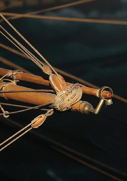
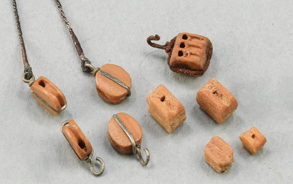
To observe the concept of “compelling impression,” one could choose from among dozens of shipboard systems. More than any, though, blocks fascinate me. They were the only labor-saving machinery used in rigging for centuries. Their utility has not changed, and their refinement continues to evolve. With a name as prosaic as “block,” they are sculpturally sophisticated. How can a few blocks speak for the quality of an entire model? Many veteran model viewers agree there is one feature on models they notice first; it differs for each person. The first things I see on a model, assuming it’s of a square-rigger, are the ends of the lower yards — they are closest to me in a display case. They are frequently fitted with a cluster of blocks. If these blocks and their associated gear are well-crafted, I am immediately engaged, but if they are crude, I struggle to observe the rest of the model objectively. (You can determine what you notice first by paying attention to where your eyes settle first on models new to you; it will take hundreds of models.)
A and B. Are you more likely to invest additional time in the 18-inch folkart model of an American ship (A) or the Rogers Collection dockyard model of a British 36-gun frigate of about 1800 (B)? (Photograph B courtesy United States Naval Academy Museum)
C. To establish perspective, consider a real, 3-inch, weathered block with a single-piece wooden shell, steel sheave, canvas-covered rope strop, and a nicely wrought steel hook. Blocks of this type were ubiquitous on sailing vessels. Next to it are six compelling nineteenth-century model blocks. They are built just like the real block except for canvas on the strops.
D. Forty old and new model blocks. In the upper left are two rope-stropped examples from the previous image (C). To their right is a group of nine metal blocks; all are brass or plated brass from early twentieth-century builders’ models except the two to the lower left in the group. The single with the perforated shell is a white metal casting by Vincent Castello from 1970. The seven wooden blocks in the upper right are my work. The large fiddle and single and the small ebony double have single-piece shells; the other four are built up of pearwood or boxwood with separate cheeks, fillers, sheaves, internal strops, and pins. The late Jim Shoesmith
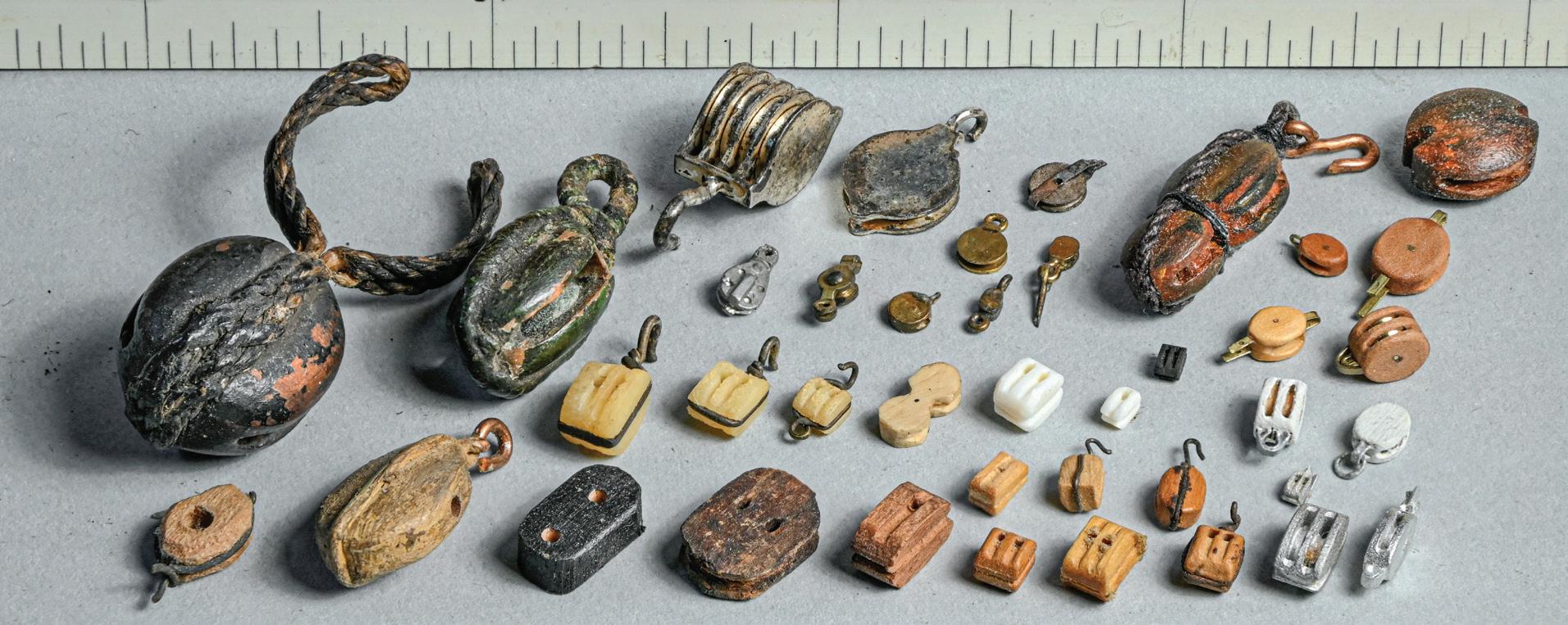
made the two white blocks with one-piece shells and silver-painted internal strops. The three wire-hooked doubles in the center are synthetic ivory from a 1922 builder’s model. The central fiddle is antique bone from the early nineteenth century. The two white, unstropped blocks are new ivory. The row of four blocks in the bottom left are from folk-art models (the black one is leather!). In the lower right are ten twentieth-century commercially available wooden and Britannia metal single and double samples with and without strops. Which of these forty examples give compelling impressions of actual gear?
E. Nine boxwood blocks. The four on the left are from a model custom built by the H. E. Boucher Manufacturing Co. in about 1915. They are appropriately flat and elliptical, have well-sculpted sheaves, and strops flattened into grooves in the surfaces of the shells. The five to the right are much chunkier, have unfaired, sharp-edged sheave holes, and unrefined wire strops. These five were marketed to hobbyists by Boucher in a 1934 catalog as “the type used on fine ship models for which the Boucher organization has been famous for nearly thirty years.” Differences between the two styles are clear. The largest block here is about 3/16 inch long. Note the lovely faux wire-rope splices on the pendants of the two blocks in the upper left.
F. A page from the 1934 Boucher catalog. The five chunky blocks to the right in the previous image (E) are what you received if you purchased from this catalog.

10
E F D C
as weathering and placing models in dioramas — to amplify a model beyond being a mere assemblage of parts. Generally, the smaller the scale of the model or the larger the prototype vessel, the more crucial this sort of interpretation is. This is because the larger the scale, the more nearly a model is like a ship and less like a model and vice versa.
One could argue that it is more important and more difficult to teach inexperienced modelers how to tell if their model yields a compelling impression than it is to teach them how to put the thing together. If they are only interested in being satisfied with the latter, then the former is even tougher.
Each winter, starting in 2009, I conduct a day-long seminar for the USS Constitution Model Shipwright Guild. The gathering is open to the guild’s entire membership, but it serves primarily as a mandatory refresher for the judges for the guild’s annual competition. The seminar is built around interpreting the above definition of a high-quality scale model. I never developed the syllabus for publication.
It is important to recognize that neither arm of our definition considers how a model was made. There is no assessment of whether entire models or components of them are built from scratch, built from kits, or built by teams of modelers. The main thing is the appearance of the finished model. The ends justify the means.
Teamwork
Please consider the notion that a ship model can be built by a team of modelers. To do this, though, we must acknowledge first that ship modeling today is principally a domain inhabited by individuals working alone. Models are built by and credited to solo practitioners. They write books, speak at conferences, and record videos about their work; they win the awards in competitions. However, suppose a team of modelers was formed to construct a single model? The adage “two heads are better than one” comes
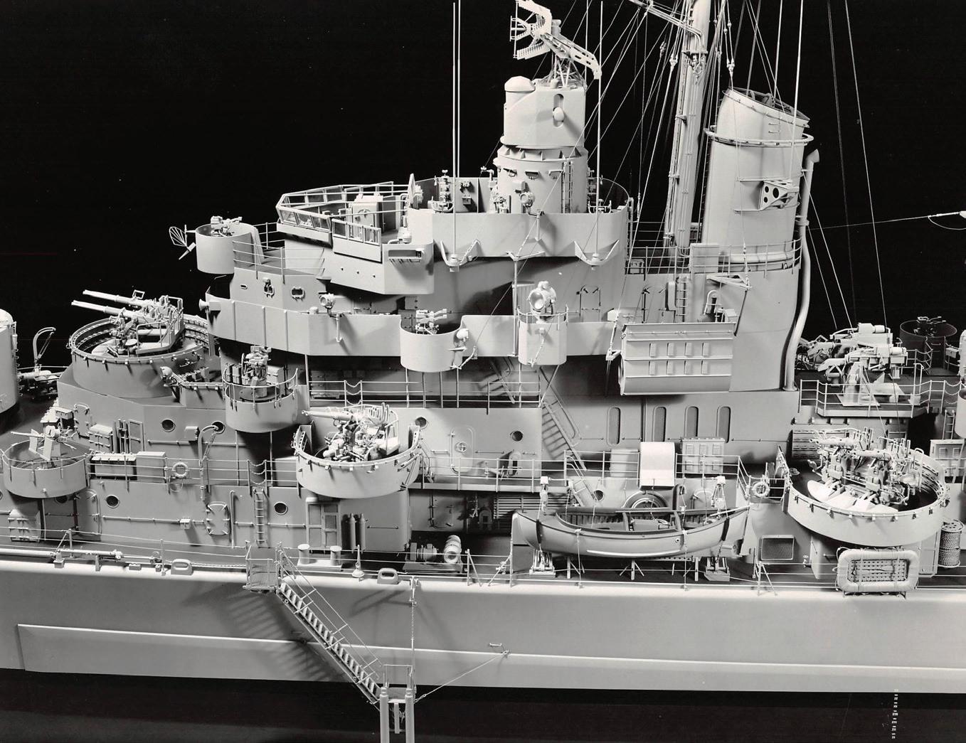
to mind. The proposition should not sound even remotely outlandish because the models that we position at the pinnacle of virtuosity were built by teams. Think of the complex seventeenth- and eighteenth-century European dockyard models of elaborate warships, nineteenth- and twentieth-century shipping office or builders’ models of steamers, and, of course, the mid-twentieth-century Gibbs & Cox models of American warships. There are no models of any similarly complex vessels being built today, by any individual, anywhere, that compare with these spectacular achievements.
We should encourage groups of two or more modelers to pool their skills and other resources.
Well-organized collaborations might yield some incredibly synergistic results. For instance, for a model sailing ship, one contributor might focus on framing, another on miniature carving, another on rigging hardware, and another on creating cordage. Or for a steel warship the foci might be hull plating, fine painting, open gun mounts, or aircraft.
If the goal is to produce better ship models, does it matter how many people work on a project? I maintain that it does not. One drawback to my thesis is that, if we agree that the work of individual ship modelers is as consistent and identifiable as that of other artists, it would be tough for all hands working on a team to match their “styles” to produce a visually cohesive model. However, if modelers are not encouraged to work together, how will we ever be able to produce re-
11
The 135-inch, 1:48-scale model of USS Juneau (CL-119) by Gibbs & Cox. This model is four times the scale of Bob Steinbrunn's USS Kidd on page 7. In other words, Kidd’s 26-foot motor whaleboat is one quarter the length of Juneau’s. (Photograph courtesy Naval Surface Warfare Center, Carderock Division)
sults that match the team efforts of previous generations?
Ship-model competitions in America and elsewhere encourage modeling excellence and offer rewards for it. Little effort would be needed to include categories for models built by groups. Team entries would certainly advance the purpose of any event.4
Longevity
Earlier, I said that model quality doesn’t depend on how a model was made, but that isn’t the whole story. My guess is that most modelers assume, or at least hope, that their creations will last far into the future. They want their efforts to be appreciated by their grandchildren, private collectors, or museum visitors. The U.S. Navy, in its “Specifications for Construction of ⅛” = 1’ Scale or Smaller Technical and Exhibition Models of Naval Vessels,” states that builders must design models so they will “last one hundred years before deterioration is visible.”5 This is a long time. Imagine your house not needing major repairs until it hit the century mark.
Such a remote goal demands that models be constructed with materials and techniques that will ensure survival. Unfortunately, success in this mission requires great forethought that is not generally observable in the short term.
If you want your model to last, to grow long in the tooth, you must render it strong. I have worked on hundreds of models — old, new, good, bad, large, small, simple, and complex — and report here with certainty that materials used in ship models are continually striving toward self-destruction.
Further, it is naïve to expect that a model will survive simply because it is strongly built. It must also be built so it can be repaired. The person in all of time who will care most for your model is you. And you have the edge. Because you built the model, you know how it went together and how to get it apart to reduce the
invasiveness of repairs. You can help the next person charged with caring for your effort — hopefully, there will be one. Make it possible to remove deck houses, to open shackles, to lift coils of line from belaying pins, and to adjust the tension of rigging components. The key here is to make these things as true-to-life as possible so their operation on a model can be understood. Realism is the common denominator, the universal solvent.
To withstand the withering vicissitudes of time, ship models must endure handling, cleaning, merchandizing, grandchildren, cocktail parties, and the cat. It seems probable that many will succumb. In the end, a model may survive because of the care taken of it rather than the care that was taken in building it. However, if the latter isn’t attended to, the model is likely to fail far sooner.
Achieving modeling results that are historically correct and visually satisfying is difficult enough. Add to the mix the challenge of making a model that will last a hundred years, and the extent of the cumulative challenge to the modeler is increased several-fold.
Many modelers intend that their models will speak as documents of their original research into some arcane aspect of maritime history, for instance how a particular vessel appeared at a particular moment. If we accept this idea, then concerns for model longevity become more important. Of what value is a research document if its author outlives it?6
Respect
Every ship model was, in the beginning, created by what I have come to identify as its “original modelwright.” The phrase could describe an individual working alone. Or, as suggested earlier, it could identify a team of modelers working collectively. You may be an original modelwright! A model exists solely as an expression of the original modelwright. It continues to exist solely because of the care that is taken of it by
12
others, and those others must strive to understand the original modelwright.
Thus, the rule that guides me is: Respect the work of the original modelwright. His, her, or their work, or so-called “hand,” should be protected or preserved when possible and emulated when necessary. Never erase or damage signatures or other markings left by the original modelwright; they contribute to the model’s significance as a document. These rules are true regardless of how good a model is, how well it was built, how well it has been cared for, or how well it tells its story. Art critic Calvin Tompkins wrote that the “whole responsibility is to [the] artist. Not to the dealer, not to the owner, not to the public, but to the artist.”7 I’m pretty sure this is how you would like to have your model treated later, when you are no longer able to tend to it.
When a client brings into my shop a model by a still-active modeler, I suggest that, if possible, the modeler be given the opportunity to work on the piece. This is most respectful to the model and its builder. And, as mentioned, the builder will be most qualified to do the work.
Permit me a pair of clarifying anecdotes. In the early 1980s, I built a model on speculation of a Herreshoff New York 30. Happily, it sold quickly. Months later, I learned through the grapevine that, despite adequate crating, the model had been damaged during transportation to its new home several hundred miles away. For repairs, the buyer took the model to someone else who was near enough to me that it would have been simple to bring the model right to me. I was upset that I was denied the opportunity to repair my own piece, to make it right for the buyer. On the flipside, when I moved to Newburyport in 1986, I introduced myself to Ed Piel, a well-known local modeler (who we’ll visit in Part Four in the Case Study 13 for the Unidentified Down Easter). I said that I hoped he wouldn’t consider my move to his city an infringement on his turf. He graciously replied that I was welcome
to hang my shingle and asked only one thing. If, as seemed likely, people brought to me models made by him, I would send those people to him. This was more than reasonable. Sticking to that request for more than thirty years helped build and maintain good community relations.8
A Model Comes Through the Door
In conversation with the client, whether individual or institutional, I discuss a model’s condition, losses, quality, and needs. I learn the client’s goals for the model and propose treatments. These can vary widely from simply dusting the model and perhaps fixing a broken piece of rigging to completely disassembling and rebuilding the model.
First- or one-time private clients will probably want to have a model restored. Institutional clients, such as museums or holders of large collections, will probably want cleaning and repairs. If they also want major work, they will likely call it “conservation,” not “restoration.”
Most models need cleaning (processes are discussed in Cleaning in Part Three,). And most models need at least some work beyond cleaning. Something will be loose, broken, or missing. If tasks are few, simple, and noninvasive, I call it “repair” work. But many models need more significant treatment. So, it is the difference between “restoration” and “conservation” that I’d like to bring to your attention.
In the museum world, according to the American Institute for Conservation, to restore a “cultural property” (an object that has “artistic, historic, scientific, religious, or social significance”) is to return it “to a known or assumed state” that is, as career conservator Sherry Phillips further clarifies, dictated by evidence presented by the object. Restoration often involves “the addition of non-original material.”9 Conspicuously, this definition does not license alterations to the nature or detail of the original object. For us, it
13
implies and encourages respect for the original modelwright.
But most ship modelers, both amateur and professional, are far from strict about this usage. Regrettably, they use “restoration” to label any more or less large-scale undertaking on a model. And, although “restoration” implies deeper immersion than “repair,” there are no limits in the craft world on any facet of “restoration;” the horizon for clarification is open and vast: nothing is sacred. Usage of “restoration” is so entrenched, yet vague, in the ship-modeling community that it is all but hopeless, today, to restrict its meaning to the museum professional’s considerably more cautious interpretation.
Let’s construct an example. A client presents a twohundred-year-old model of a square-rigger that lacks, say, a set of steps to connect the main deck with the quarterdeck. Such steps were common and necessary on real ships. Many modelers would see an opportunity to make the model more accurate by adding steps, and they would consider the addition part of their restoration. But museum professionals will search for evidence — glue footprints, fastener holes, paint gaps, and the like — that steps had been fitted originally on that model. If there is no evidence, they would not add steps, and the addition of steps would not be restoration; it would be disrespect. They listen to evidence provided by the object and, by doing so, they respect the original modelwright.
Museum and independent specialists called “conservators” employ another practice. This is “conservation,” and it is somewhat more complex. The Institute for Conservation defines it as a process “devoted to the preservation of cultural property for the future.” In turn, it defines “preservation” as “the protection of cultural property through activities that minimize chemical and physical deterioration and damage and that prevent loss of informational content.”10 While working with several conservators over the course of thirty-five years, two aspects of conservation grew clear.
To me, the less imperative aspect involves being educated in the chemistry of objects. All conservators with whom I’ve spent time apply a solid knowledge of how materials, adhesives, and finishes react with one another. While I attend to what we might call the shippy aspects of model jobs at museums, conservators prescribe the limits of materials and processes that will be appropriate to use. Chemistry is not my forte, so I welcome, appreciate, and adhere to conservators’ input.
Now, the aspect of conservation more important to me is that everything that has become part of an object becomes a part of that object’s story — its “informational content.” What does this mean to us as ship modelers?
Let’s say a client presents that same square-rigger already fitted with the steps. By close examination of fit, finish, and materials, the conservator can see that the steps are not original gear. A previous hand was not “restoring” the steps because there is no evidence the steps were original. But the conservator, accepting the entire object, will leave those steps aboard because everything, original and new, contributes to the model’s overall story. In this example, someone built a model, but left off the steps. Who knows why? But then, a century later, someone added steps because they would “improve” the model. The conservator recognizes that even errors by previous hands become part of and relate a model’s history. So, the conservator acts conservatively and alters as little as possible. The conservator preserves and stabilizes but doesn’t correct. As Phillips explained, the conservator “leaves [her] ego at the door.”11 This can be interpreted to mean that the ego of the piece is more important than the ego of the conservator and that the piece should speak louder than its custodians.
Another hypothesis bears consideration. That same square-rigger is presented. There are no steps, but clear evidence indicates they had been fitted originally. Notches in the quarterdeck rail show wood slivers em-
14
bedded in old, dried glue, and there are nail holes in the deck. There were steps! Now the conservator has license to build and install new, replacement steps. This is proper restoration, dictated by the model and respecting the original modelwright.
These differences will not be appreciated by all clients, but they will be by some. Thus, it is important to be able distinguish various approaches to treatment.
With full disclosure in mind, I must declare that, when starting out, I didn’t know about, let alone apply, any conservational theories. Several models fell victim to my early heavy-handedness, and I assure you there are a couple of jobs I wish I could undo. Fortunately, I gradually developed a lighter touch and learned to respect the models and their builders. I approached a fork in my path and left the amateurs’ version of restoration at that fork. I now avoid almost entirely the use of “restoration” in favor of other words.
Never Upgrade the Model
For another perspective, I should add that before learning about professional conservation, I had, from time to time, people assisting me with repair work. To help guide them, I had independently developed what is an effective working corollary to the policy of respecting the original modelwright. This is: Never upgrade a model. I explained that when it’s apparent an original modeler made a mistake — installed a blatant anachronism, say — the error must be preserved. (Conservators consider removal of original work, even if it is wrong, among the most scandalous taboos.) Further, it’s important to match original workmanship. If it is fine, then repairs must be fine. If a model was made crudely, then, ironically, high-quality repairs must be crude. I told my colleagues that a model builder creates a world, an environment, and a story. It’s incumbent on us to understand and enter that domain, to attempt to be the original modelwright. The availability of modern research, materials,
and tools does not justify the violation of an artist’s intentions and craftsmanship. The goal is not to correct the original modelwright, but to re-invigorate him. If a person repairing a model wants to make a “better” model, he or she should build an entirely new one.
Two Debates
A pair of debates seems always to be on-going about ship-model work. To understand the first, imagine an old but historically relevant plank-on-frame model that has been severely damaged and is missing quite a bit of its structure. The model is going to be rebuilt for a museum exhibition. The question is: Should replacement work be executed so it blends inconspicuously with the old model, thus making the model appear whole? Or should new work be made to contrast with the model’s original fabric so viewers can make no mistake about what portions of the model are new and old? My response is to make the model appear whole. This is because inexperienced viewers will likely not care about and will be confused by the visual evidence of the rebuilding. They will see it as a part of the portrait of the ship. Conversely, informed viewers who care about the rebuilding will be able to distinguish between original fabric and new work no matter how well it’s made to blend in. I would only support the idea of contrasting work if the museum’s story is primarily about rebuilding the model.
For the second debate, it’s important to know that, within most old models, one can find debris of one sort or another. There may be dust, shavings, bits of woodworking or rigging, evidence of infestation by rodents or insects, and more. What is to be done with these things? Items that are recognizable as having been fitted to the finished model, but, for one reason or another, came adrift and were tossed below for safe keeping, may be reinstalled externally with confidence.
15
Shavings, dust, and scraps, however, seem to have no value. Curators and conservators do not like to discard anything because everything may contribute someday to the model’s story, even if its language isn’t yet known. One policy is to leave everything in situ that cannot be reinstalled confidently. The thinking is that the model is the best place to keep material against a time when as-yet undeveloped analytical processes may reveal more than is possible today. This policy avoids the need to archive things separately from the model — the model is the file cabinet. Another policy is to remove as much debris as possible. The advantages are that the model will look better, that some buried items may surface that might not have been noticed, and that the debris can be studied later without reinvading the model. The model also profits environmentally because impacted dust can retain moisture, which is usually debilitating, and because the more that air circulates, the healthier the model’s fabric will be. The only inconvenience is that a filing system and space are required to catalog and store removed three-dimensional materials.
A Few Perspectives on the Arcane
The remaining eight sections of Part Two are musings. They are not directly related to ship-model building or repair. However, I suspect that, from conversations I’ve had through the years, these topics burble occasionally to the surface of many modelers’ minds in one form or another. This seems to happen when they are engaged in lengthy, repetitive tasks that occupy the hands but that leave room for thought. I hope that their inclusion here will help solitary modelers feel less isolated; in an obscure way, we share a common work space.
Profoundly Handmade
Seventeenth- and eighteenth-century British Navy Board models, which we revere, were made before
the advent of steam power and electricity. Modelers operated spectacularly with manual frame saws, chisels, knives, bow and pump drills, planes, gravers, scrapers, and hand or pole lathes. And they labored with no electric lighting to enable work in dimly lit rooms or on gloomy days, which there were plenty of in England. This was before the refinement, in the nineteenth century and later, of the modern circular saw, band saw, power sander, and drill press, not to mention the incomparable engine lathe. When those earlier ship modelers first saw a circular saw, I’ll bet they cried, “Hot damn! Gotta get me one o’ those!” They immediately recognized a tool that could be adapted, with effort, to their tasks; that could make their work easier, faster, and more precise. I’ll bet few condemned the device for its lack of being traditional.
We take our electric, circular-motion tools so absolutely for granted that we forget they were once technologically advanced. Imagine building a complex plankon-frame model and all you have is a hand-powered frame or jeweler’s saw, scrapers, and planes. Ripping a hundred feet of dimensioned boxwood decking (by candlelight!) suddenly becomes daunting. To prepare a board, you must handsaw and plane it to consistent thickness; scribe off a plank; handsaw that to width; then scrape it smooth. The planks had to be identical, and they were, to tolerances we have trouble attaining with the Preac-brand table saw. If we think of our work today as being handmade, even with our power tools, then we must think of the master seventeenth- and eighteenth-century modelwrights’ work, who literally worked with their hands, as being profoundly handmade.
Nowadays there are those who think innovations like photo-etching, 3D printing, and other computer-based techniques should be rejected chiefly because they are not traditional. There is no reason to suppose that ship modeling has evolved to its ultimate phase. So, let’s look back from the future per -
16
spective of, say, the twenty-fourth century. By then, the technologies of table saws and computers will be relatively the same age. They will have been around always, and modelers will be using both without qualms. Why? Because computers make production of ship-model components easier, faster, and more precise — exactly like the table saw. This will occur regardless of how we label or shun today’s breakthroughs. With the present era’s exponential increases in developing technology, there will be even newer methods about which we haven’t yet imagined a glimmer. 12
Personally, I favor working with wood, brass, and natural fiber line. I just like the stuff; I grew up with it. But progress is important. We should not make blanket rejections of technology simply because some processes may not yet be proven.13 If we do not experiment with new ways to solve old problems, we would not be human; we’d still be living in caves, perhaps under rocks. The obvious fact is that if we do not experiment, we will never discover what will work to create models that will last a hundred years.
Tryst
Over time, I’ve asked many ship modelers why they install features that will never see the light of day inside their models. I suspected there must be some deep-rooted reason, some drive, that those modelers were reluctant to articulate. But they seemed to guard their reasons. Their pat answer felt too flip: “Because I can.” This didn’t tell me anything; it didn’t sit well. I felt like my question hadn’t been given any real thought. Then, during a model repair trip to Long Island’s North Fork in 2011, the answer came to me in the small hours of the morning. It is this: Ship modeling is solitary, and, as such, trends generally inward. A modeler really doesn’t want to admit his feelings, whether he can express them or not, any more than someone wants to admit an affair of the
heart that occurs outside established boundaries. The modeler who builds details no one will see is looking inward, toward his own motives for modeling. They are private, possibly even secret. He is having an assignation with his muse.
Spirit
My eyes opened briefly to see the barber intently trimming my beard and mustache. It was 2008, the first time in perhaps thirty years I was getting my hair cut by an unfamiliar barber in another country. It was a highly recommended, old-world-style shop. Three efficient barbers were working, six men were waiting. It’s a risky business. How do I tell him what I want; will it turn out okay? The barber was completely focused. Only inches from my face, his eyes didn’t blink when mine opened. I was glad of that. Right then, I wondered if I look at ship models with that barber’s intensity. It might be harder to understand what I wondered next. Does a ship model perceive me looking at it? Does it feel my concentration? Does it know if my hands are steady? Does it enjoy my attention? Can it tell if my tools are doing the right things? If so, is it grateful; if not, is it resentful? Can it remember? If I mess it up, can it affect the effort of future hands? Does it understand I am trying to help it? Does it feel refreshed when I’m done?
I know I’m anthropomorphizing an inanimate object. However, from experience at sea, I have come to believe that some vessels have genuine presence, that they have spirits. They seem to enjoy being the vessels they are, or not, and comport themselves accordingly. Why not models? Do some models see me like I saw that that barber?
The Orbit of Pluto
Everyone knows the Law of Lost Parts: A lost part is always found in the last place one looks. But there is an

17
Does this large model of an eighteenth-century warship perceive that I am peering into it with the same concentration as that barber had when he looked at me?
obscure First Corollary: The smaller a lost part is, the more likely it will be found in the last place one can look. In 2014, a ferocious deadline to finish a model was looming, and I was making the gang of blocks. They were built up with separate cheeks, fillers, pins, sheaves, and internal metal strops. The largest was 5/16 inch long, and the average time spent on each was considerable. One popped out of my grasp, fell to the floor. I searched the area on hands and knees with a flashlight to produce raking light to amplify the block’s shadow and make it more visible. No luck. I spent more time searching than it finally took to make a replacement. Some modelers say that such parts are sucked into the black hole of the Milky Way. I, however, believe they enter the Belt of Missing Parts just beyond poor little Pluto’s orbit. And the proof was that block. If it had been sucked into a black hole, it would have been gone forever. But, lo, more than a year later it reappeared in a cabinet, at least 10 feet from where I had been sitting. This happens frequently enough that I have formulated the Law of Lost Parts, Second Corollary: The time required to locate a vanished part is inversely proportional to the part’s mass yet directly proportional to the part’s building time, these factored against the time spent searching prior to the realization that, yes dammit, you’ll have to remake the part anyway.
The Zone
When doing repetitive model work, I sometimes find myself in the Zone. The work is flowing, thanks to experience, practice, and muscle memory. I think about the actual moves I am making — holding the pencil so it marks properly, moving the knife so it cuts the right bevel, snaping the end of a wooden strip without tearing — things like this. But I think not only about processes, I am also mentally verbalizing them in phrases or sentences. There are two side effects. First, I’m pleased that I can convert action into language
spontaneously. Second, if I want to save the language, I must write it down immediately, and that might take me out of the Zone.
The Zone embraces me in another way when I’m concentrating on something numbing, like rattling down shrouds. At the start, I find myself totaling the number of times I’ll have to repeat a task, in this case tying clove hitches. Then, in my head, I serially recalculate the percentage of the job I’ve finished so far. Eventually, the numbers fade — the Zone takes over. I usually resurface at about the 90-percent mark, then figure percentages down to the finish.
My mother, a music major at university, encouraged me to listen to classical music; popular music had no place in our home. I didn’t question this: It was what it was. I realized only lately that this was beneficial in a way I’d never considered. Mother recognized I was fervent about ship models, and I suspect she understood how much effort and time they would require. She knew that classical music also required enormous effort and concentration to compose and perform, especially when compared to pop music. Perhaps seeing classical music and ship modeling in parallel, she may have understood that listening to the former offered the appropriate environment for creating the latter. I didn’t learn hard facts about classical music, but I absorbed its moods, complexities, and power. Long compositions helped me focus on lengthy problem solving in ship-model work.
Later, when I turned pro, each ten-hour workshop day was filled with music — classical, jazz, rock, in that order — but now I prefer just the steady whirr of a fan. I’ve asked other modelers about the Zone. Bob Steinbrunn refers to the Zone as the “alpha state,” and says that “all great artists” feel a “flash of irritation” when they are dragged “back to full awareness” by interruptions. Joel Sanborn “can’t listen to music with lyrics…music needs to be background ‘noise’. Opera is okay if it is in Italian or German.” David
18
Antscherl says he meditates once he’s “achieved the muscle-memory rhythm” and listens “to classical/baroque music to help time pass enjoyably.” Clay Feldman “used to listen to NPR,” but now has “de-zoned altogether” with “no more radio at all.” Bob Filipowski suggests that the Zone has a “dark side” where he is so focused he forgets about nearby fragile objects and occasionally breaks them. “That brings [him] back to reality quickly.”14 Some modelers relieve long Zone sessions by rewarding themselves with other tasks. My preference is to just steam through to the finish — I like the Zone.
Autodidact
When people ask how I learned my trade, it pleases me to reply that I am an autodidact. But is this entirely true? Granted, no schools offer formal curricula for researching, building, and caring for historically accurate and significant ship models. (However, in recent decades, brief ship-model conservation workshops have been offered by a couple of European institutions.) Nonetheless, there are other ways to learn. For instance, I have retained a perfect mental video of watching, when I was sixteen, New York modeler Don Peterson’s hands manipulate a miniature plane to shape a grab rail for a yacht model’s deckhouse. Whenever I work with trained conservators, I absorb everything possible. These generous folks didn’t know they were teaching me, but I was learning from them. I’ve read countless books and studied other people’s models, old and new. I let them all teach me about ship modeling. I’ve spent thousands of hours at the workbench, often making mistakes and redoing things. Does this mean I am self-taught?
For more than twenty years, the Forbes Trinchera Ranch collection was in my care. I was assisted there on many annual trips by Racket Shreve, a fellow modeler and marine artist. We received from the client no guidance whatever on what we were to do. Racket
compared us with a M.A.S.H. unit. We worked in the ill-equipped field, triaged the collection’s needs incessantly, and did what we could in a hurry to keep models intact. I always hoped the owners would take a more active rôle. Had they, though, we would never have learned as much as we did. This was on-the-job training by the models themselves. Was I self-taught, or did I let the models teach me?
Sometimes I find myself not liking a model I’m working on. But I know that, through the effort of the work, the model will teach me something; I will learn from it, and I will like it more because there is something of me in it. If I don’t learn something positive from the model, I haven’t put enough of myself into it.
Anxiety
Anxiety affects my ship modeling. After fifty years, how can this be? Suppose I am building a set of fittings for a model and consider them finished well enough to move on. I start thinking about the next task and that it will be challenging for any of several reasons I’d prefer to avoid. So, rather than advance, I take shelter by retreating to the earlier project — by adding another level of detail, say. There are two results. First, the model gets better. Second, I have delayed the inevitable. But soon I can stall no longer, even if that next step does seem too difficult, complicated, or scary.
Now, when avoiding a task for these reasons, I must remember “fear is the mind-killer.”15 This central message from Frank Herbert’s Dune is that anxiety prevents one from thinking through a problem to the point of solution or action. It is key to finding success. So, what do I do when I don’t know what to do, or how to search for a new approach, process, or outlook?
Another venerable maxim becomes operable: Do something, even if it’s wrong. The paralysis of inaction can be cured by taking a first step, even if I’m not sure it’s on the right path. For instance, a wing transom for a large wooden vessel’s frame incorporates complex geom-
19
etry that is particularly tricky to visualize, to pin down in space. The timber usually curves and tapers in a couple of directions and abuts neighboring timbers without the convenience of right angles. I can’t visualize how to start. Finally, I draw what I hope is a likely line on a piece of wood and cut it. I will know immediately, by whether I can picture the following step, if I have discovered the correct first step. If I’m not sure, the second cut cinches it, even if it tells me I need to restart, and I know I will succeed. If the path is altogether wrong, I recall the lesson of a friend from my Navy days: “If you try something three times and it still doesn’t work, try something else.”16
You may think I’m nuts for assessing problem solving this way, but there it is. It has prodded me to deeper levels of accomplishment consistently for fifty years. There must be something to it.
About Money
It is inevitable that, during the question-and-answer period following every talk I present to lay audiences, the subject of how much I charge for my work will arise. My policy is to say either how long a project took or how much it cost overall. But I never reveal both because people want to do the math to learn my hourly rate. When asked directly, I say that it’s business between my client and me. My observation is that clients don’t care what my hourly rate is; during my career, I may have been asked only three times. Clients are only interested in the bottom line.
Amateurs boast about how long projects take them as if longer is better. Professionals boast about how quickly they do projects because they need to keep hours down.
My work is divided into three areas: half-model building, model repair and conservation, and full-hull model building. The list inversely orders profitability. In the early 1970s, I sometimes worked for as little as $2 an hour, and I could make a profit at that on some projects. And there is no doubt that full-hull model building, which requires thousands of hours, will generate a lower hourly income, on average, than shorter projects simply because, for full-hulls, the hours can really pile up.
I know roughly what academically trained, independent conservators charge (and get, judging from their backlogs). Not being an accredited conservator, I do not bring their level of expertise to the bench. Thus, I have always kept my rates lower.
Incidentally, it’s ironic that the security of an extended backlog erases the joy of spontaneity. I always know what I’ll be doing next week, next year, and the knowledge is debilitating.
In the 1970s, I had a mentor who did exclusive yacht designing. When I asked him about charging for custom work, he counseled firmly: “Never give a client anything to complain about except the price.” This was terrific advice for a young practitioner. And I heeded it. But as I have wandered into my seniority, I find it increasingly difficult to meet deadlines. ¯
20
Part Three Practices and Applications
Why Are They Here?
What brings ship models to my shop? Models suffer many woes that can be sorted into two basic categories. Let’s call them external and internal issues. External issues might be considered those things that happen to models. They are generally severe. Models are damaged by poor handling; by careless viewers; by passersby; by heat, smoke, and fire; by objects falling on them; by falling on the floor; and so on. Such catastrophes and more are easily understood, and the results are obvious.
One client called to say he was sending a small, bone prisoner-of-war model for repair; it travelled across the country in a paper mailing envelope; do I need to describe it? The upper masts and rigging of an-
other bone model had been crushed by a customs agent who reached zealously into a shipping carton before looking to see what was there. I’ve rebuilt more than one steering wheel that shattered when someone at a cocktail party saw it and said, “Look at that! I wonder if it works”: nope. A collection of large models suffered a fire; models that weren’t charred were covered with smoke residue. One of the first models I built was swept off a mantel, thus one of my earliest professional jobs was rebuilding my own work. Another model and its display case were mauled by airline baggage handlers. And another, “professionally” packed and shipped to me for minor repairs, arrived with its brass mast bent into a double-S curve and penetrating the carton top; all the rigging was destroyed. The first time I saw one 11-foot builder’s model of a British liner, it was covered
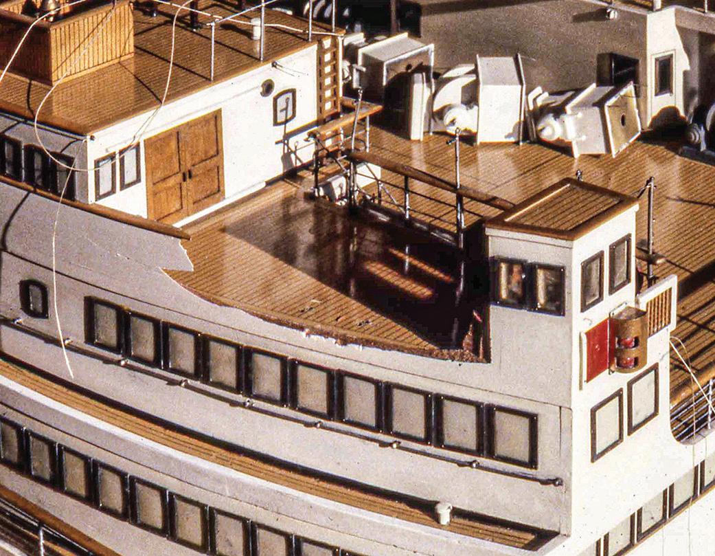
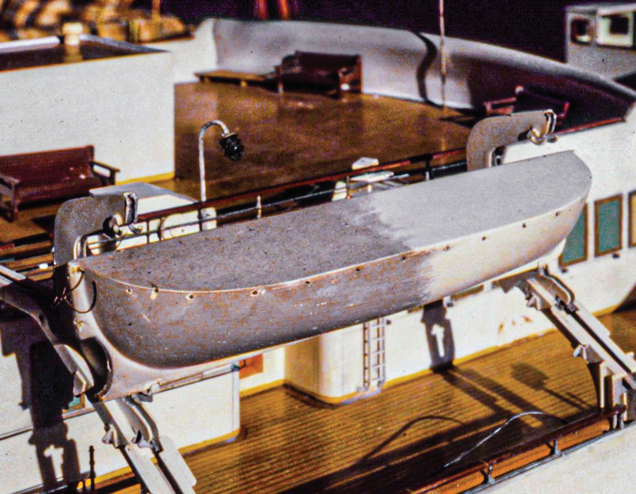
Far left. Smoke damage. The lifeboat’s uncleaned aft end shows how smoke residue completely enveloped this 142inch, 1:48-scale builder’s model of the Royal Mail Line’s short-lived 1948 twin-screw turbine ship Magdalena Center. The port bridge bulwark was slashed by a shard of 3/8inch glass falling from a shattered case. Detail from the 138inch, 1:48-scale builder’s model of the New Zealand Shipping Company’s 1929 twin-screw passenger liner Rangitiki.

Left. A foam-like drop of melted acoustic ceiling tile grips a bent lifeline stanchion, and one ivoroid (or other early synthetic ivory) block has partially melted in its wire strop. Parts are from the 121-inch, 1:48-scale builder’s model of the British India Steam Navigation Company’s 1922 twin-screw passenger steamer Mulbera

with fresh snow inside a house. Then there is the irony of models that are severely damaged by the shattering of the cases intended to protect them. Not all instances are so radical, certainly, but you get the idea. Internal issues might be more difficult to recognize and identify. Rigging might move enough to chafe to the point of failure. Chemical reactions within parts can cause them to disintegrate. Wooden components can dehydrate to the point that glued joints in them fail and they shed finishes. Creatures greater and smaller — mammals, insects, worms — can leave unpleasant residues of residence within models. Encased models might struggle in a static, acidic miasma that attacks rigging and metal.
In about 1980, a woman arrived with a clipper ship model that was so dehydrated that its glue joints had separated, and its wood collapsed with only slight pressure; it wasn’t balsa. A waterline diorama of a square-rigger sailing in a sea made of cotton batting had been sealed in a case for a hundred years; when I opened the case, fetid air left me gasping. Rigging line is often so rotten from exposure to ultraviolet light it powders when touched. Models in a New Hampshire collection were coated with crystalized mouse urine flecked liberally with accreted droppings. Sails on a

large, schooner yacht model had been molded to shape with starch that was attacked by mildew (probably because the model was in a too-humid environment); the waste fell to the deck and destroyed its varnished finish. These conditions were all bad, but each was the start of a new adventure.
First Looks and Appraisals
Initial contact with a new client can come in one of several ways. For me, it can be a face-to-face meeting or via telephone, surface mail, or e-mail. The most revenue-generating method, I find, is the telephone. During initial contact, I generally ask for basic information about a model or collection — what it represents, how large it is, where it is, how old it is, if models are cased, if model builders are known, and so on. Until asked, I never mention quality because everyone wants to think they have a good model.
Assuming I first see a model in three dimensions, initial glimpses provide me with immediate impressions of its issues, and I’ve learned to trust these impressions. With the model under good light, I survey what needs cleaning and repair. If it is older, I wonder how much of it is original. What has been done by

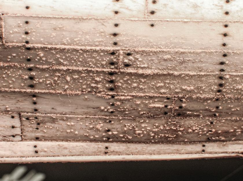
22
This prisoner-of-war model’s masts and rigging were crushed by the collapse of the glass case intended to protect it.
Infestation. Those items that look like spider webs and dead flies are spider webs and dead flies. Detail from the 116-inch, 1:48-scale builder’s model of the Peninsular and Oriental Steam Navigation Company’s 1901 twin-screw passenger liner Sicilia
Chafe. The mizzen topmast staysail sheet pendants (arrows) secure to the halyard block in its lowered position in the main top. The sheet pendants crossed the top railing, then led down. The swaying motion of the loosely draped sheets caused them to chafe to failure on the sharp-edged railing. Detail on the 36-inch (or so), 1:48-scale modern model of the British 22-gun corvette Andromeda of 1810.
Like new snow on a warm brick patio, a feathery bloom of mold or fungus traces the seams between the bone planks on this 18-inch prisoner-of-war model.
other hands since the original modelwright? I look for consistency in scale; depiction of detail; finishes; rigging line and knot work; and so forth. I check for previous repairs. While inspecting, I probe gently with tweezers. Are pieces firmly attached? Are finishes bonded or peeling or lost? How fragile is rigging line? Is everything present or are things missing? More abstractly, I’m asking: Is the model inviting? Do I want to get involved? Will it be a pleasure or a job? I listen as the model dictates the amount of care it will require.
A preliminary goal is to demonstrate to the owner that the model’s care is important to me.1
A good way to do this is to involve him or her with processes or techniques that I will use. If the model is dirty, which most are, I do a test cleaning with the enzyme technique (more on this later).
The examination is simple and mostly visual. It yields enough information to identify a model’s salient problems and to serve as a basis for estimating work that needs to be done. The estimate will usually be good for the client and me. Its formality will depend on our relationship. Beware of customers who say or imply that money is no object — it will be.
Estimates contain the proviso that they may be revised if unforeseen issues arise that require more sophisticated observation than I can provide in-house. Here are a couple of examples: A small model named L’Mars at the Museum of Fine Arts had extremely fine, fragile-looking, shiny rigging. Chemical analysis in 1992 showed the rigging was sheep’s wool saturated with pine resin, and high-power optical microscopy revealed the shine was attributable to fine brass and copper filings captured in the resin; the rigging was robust.2 In 2004, the 1773 model of Princess Royal at the U.S. Naval Academy Museum required disassembly, but we needed to know first if its structure depended on metal fasteners. A visit to the radiology lab at the school’s clinic produced X-rays that showed practically no fasteners at all. These noninvasive investigative
processes were performed by outside services prior to working on models.
Investigating the interiors of medium-sized and larger models is easy and inexpensive with borescopes (which are used by tradespeople) and endoscopes (which are basically refined borescopes used medically). Hand-held X-ray fluorescence spectrometers instantly analyze the percentage of each element in a specimen and report its metallic composition. And a small, ultraviolet-light flashlight is handy for identifying types of glue and for finding and reading obscure penciled information on objects. The one I use is made by Inova.
If I can’t view a model right away, I request snapshots of it. This was cumbersome and often resulted in extended delays in the era of film photography, but it is simple with today’s ubiquity of digital imaging and e-mail. I ask for pictures from several angles, and suggest they include specific damage and something of iconic size, like a ruler, to help determine the model’s size. Ironically, I’ve learned that the more precise my picture-taking instructions are, the less useful the pictures turn out to be. Keep instructions simple. First looks at images are usually reliable, but I let them settle. A day or two later, I study them more deeply to see whatever can be seen. Then the client and I chat again. Institutions and veteran collectors are usually fluent in the language of ship models and appreciate the nature of what they have. But many one-time clients are unfamiliar with these things. They want to learn, but it is counterproductive for me to inflate a sense of quality if it isn’t there. I shoot straight when I speak directly to a model’s quality with a client.
Many one-time clients present models built by their hobbyist fathers, grandfathers, or husbands. (I have worked on models that women helped build, but never on one built solely by a woman, that I know of.) I realize I’m generalizing, but such models were frequently built from published instructions or kits; over time, they have been cherished but not well cared for.
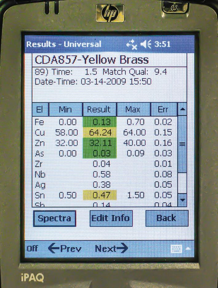

23
The readout on a hand-held X-ray fluorescence spectrometer provides the percentages of iron, copper, zinc, and other elements found in a model anchor. The device's software calculated the resulting alloy to be yellow brass.
The anchor assessed in the above trial was about 2 inches long.
Owners will be surprised to learn that maintenance expenses will exceed, sometimes substantially, the model’s value. Owners are then faced with the tough job of quantifying their sentimentality.
Understandably, folks want to know what their models are worth, either in the marketplace or for insurance purposes. Thus, I am asked occasionally to assess the monetary value of a single model or a collection. This is a service I do not provide. A qualified appraiser must have considerable knowledge of prices that models fetch in galleries and auctions. I do sell models I have made, and I have steered collectors toward models they might appreciate. However, it has never been my business to broker models made by others or to request finder’s fees. A person might say they don’t need an official appraisal then add quickly, “Well, you’ve worked with models all your life, surely you can give me a rough idea of what mine is worth.” A rough idea is an appraisal.3 In the end, I am healthier for maintaining this policy; no one comes back at me for misjudging what a model might bring if they try to sell it.
When a new owner plans to acquire an old model, he or she should be prepared to have its condition assessed by a ship-model professional. This can be done in person or with a group of high-quality photographs. The analysis will hopefully educate the owner about issues concerning the model’s age, authenticity, condition, and quality; it should discuss how the model is or can be displayed and protected in its new owner’s location; and it may include advice and estimates for treatments.
Documentation
A model repair project will likely involve two types of documentation. The first is the material you will gather to learn about your subject, both model and vessel. The second is the material you will generate during the project.
As for the first, track down everything you can; you can’t have too much. The quantity and nature of available information will differ for every project. Check your own library; museum libraries, models, and art collections; the National Archives (if it’s a deep project); and so forth. For a given vessel, there may be primary source material, including original plans or other technical drawings, builders’ half-models, photographs, paintings or other artwork, logbooks, and personal journals. There may also be secondary material in books, magazines, and other interpretations of the vessel including modern models and paintings. Seek answers or at least give reasonable consideration to every question you can think of.
When reconditioning an existing model, that model is your primary source regardless of its quality, pedigree, or provenance. Other material about the vessel may be useful, but it must serve only to guide how the original modelwright interpreted the vessel for that model, not to guide alterations to the model. Kits and plans developed for model builders are not generally reliable unless you know that the model on your bench came from a particular kit or plan. Remember: other models are generally secondary sources, at best, so they shouldn’t be trusted.
Establish for your gathered documents an order of credibility. In which documents will you put the most faith? The easiest and most obvious order is chronological because it helps develop the vessel’s story for you. When referring to them, always look through them in that order. I enforce this by copying documents, plans, and images to 8½- by 11-inch paper and putting the pages in chronological order in a binder.
The second type of documentation will open with the results of the observations and analyses discussed earlier. You should photograph the model. Thoroughness here depends on the complexity of the job, but the rule is that you will never have too many images. They will be key to reassembling the model. Keep a written record of what you do. Include all specialized
24
materials and techniques you employ. This record will be the basis for a treatment report that you prepare for your client.
Memory Boards
To facilitate cleaning or extensive repairs, it’s sometimes expedient to remove so many parts from a model that remembering where each belongs is impossible. Another form of documentation is needed. An alphanumeric cataloging system might be a helpful solution. This will require placing on each part marks that must later be removed, or it will require hundreds of labeled containers that will create frustrating clutter and waste. I developed an elegant alternative for disassembling Princess Royal in 2006 at the U.S. Naval Academy Museum.
With a digital camera, capture a series of straightdown images of a deck. The number of images depends on a model’s length. In your preferred image editor (I use Adobe Photoshop), align the images to form a layered composite of the entire deck. Print each layer so it is somewhat larger than the model’s size. Attach the images to a sheet of foamcore with spray adhesive. The result is a photographic deck plan. Now, remove a part from the model and place it on the photo of itself, keeping it properly aligned: fore and aft, top and bottom, port and starboard. With a large needle in a pin vise (or a similar tool), poke a hole through the foamcore on each side of the part. Span the part with a length of soft brass wire bent like a staple, insert each wire end through a hole, and twist the ends together underneath. Repeat; two wires for every part. The result is a panel with parts ordered, secure, visible, and handy. A separate panel will be required for each deck of multi-decked models.
It is tempting to think that many of a model’s parts are interchangeable — like rail stanchions or deck cleats — so it isn’t necessary to keep track of where each one goes. But models are fussy about this. It does matter. This is when this system pays off.
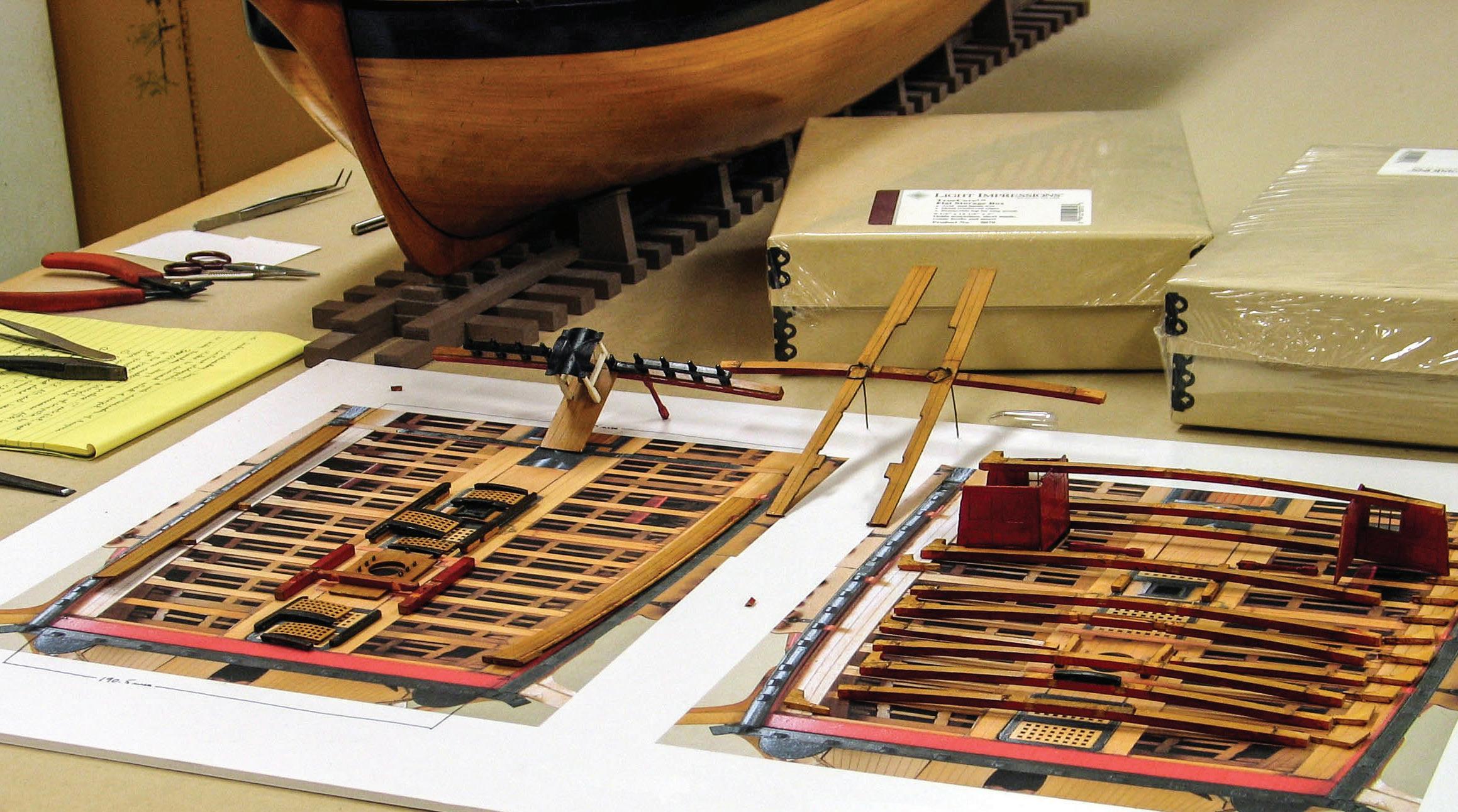
A woman named Katherine Twomey was visiting the museum and watching me disassemble Princess Royal. She was curious about the analog system I was using to catalog parts and suggested the foamcore sheet be called a “memory board.”4 The handle stuck. Later, snipping the wires to release the parts from the memory board and reinstalling them on the model feels a lot like building a kit!
Means of Support
Frequently a model must be supported for work when its own cradles, pedestals, or other display components aren’t available. I’ve devised a few dependable systems for this. The easiest, especially when working away from home, is a simple cardboard box. Conveniently available in almost any size, a box should be chosen that is shorter and deeper than the hull. With a utility knife, cut a notch in each end. The notches only need to fit the hull approximately but should be deep enough
25
Memory boards. Components and single pieces of the forecastle deck laid out on memory boards for the 55-inch, 1:48-scale, dockyard model of the British 90-gun second-rate Princess Royal of 1773.
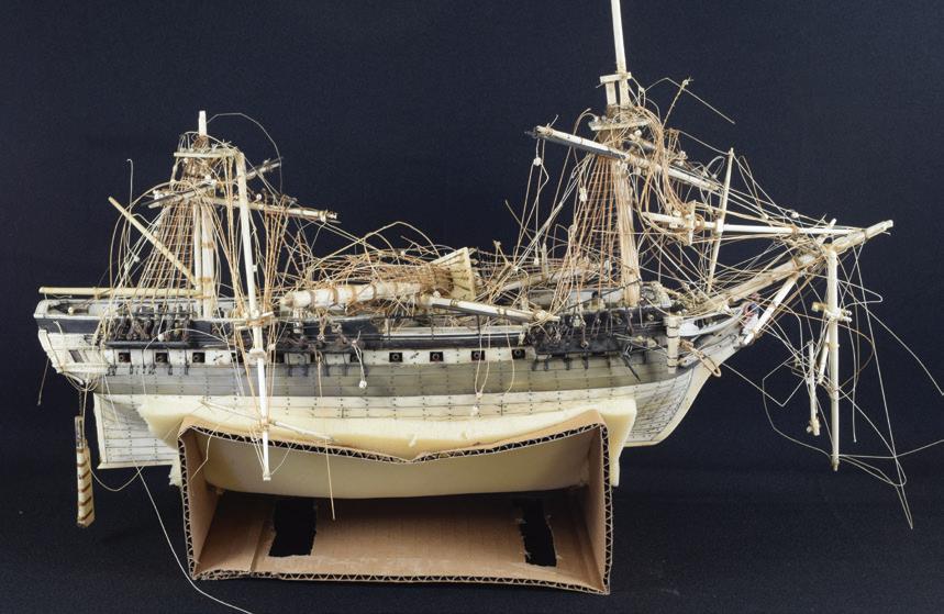
to keep it stable. If the hull’s finish is fragile, line the notches with foam, cloth, or a paper towel. This solution is quick, inexpensive, and disposable.
Once, while on the road, I needed to support a model steamship that, at about 6 feet long, was too heavy for a cardboard box. I quickly sketched a structure that could be made of 2- by 4-inch stock by carpenters at the site. The support was a rectangular framed base with an upright at each corner. Lengths of sturdy cloth were stapled across each pair of uprights to serve as slings to support the model. Differently shaped models can be accommodated by restapling the slings.
Then it occurred to me that a fully adjustable cradle would be useful. Inspired by travel lifts at local boatyards, I designed and built a device that could accommodate a wide range of models. Wooden pieces are ¾-inch plywood. Size adjustments are easily made by shifting bolts that drop into holes in the athwartship and longitudinal pieces. Each sling is a length of nylon webbing that is secured with screws to the upright on one side and takes up on a reel on the other side. The cradle can be adjusted to accommodate models from about 4 inches to 14½ inches in beam. When the straps are maximally separated by 36 inches, the cradle can support models up to about 10 feet long. The device can be disassembled for travel to off-site work.

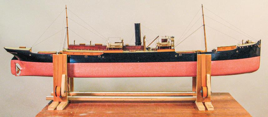
Howard Chatterton at the U.S. Naval Academy Museum devised a system dubbed the “gallows” to help reorganize spars and rigging of crushed models without stressing the rigging. The device supports from above instead of from below. In my version, two arms are mounted about 2 feet apart on the shelf above my bench. A rod or dowel spans the arms over the model’s centerline. A string is tied to a spar, then draped over the rod. An electrician’s retractable-hook test clip maintains tension on the string. The idea is to lift spars
gradually without threatening adjacent rigging, to sort out related rigging, and to gradually coax the spars and rigging to their proper positions. When idle, the gallows’s arms swing inward to stow conveniently next to each other on the shelf.
About Tools
I am neither tool maven nor collector. I acquire tools to do specific jobs well. If I need to construct a tool for a particular job, I spend little time on its aesthetics. If, when you look at a plane iron, knife, chisel, or gouge edge-on, the edge reflects even a slender silver line, or if the blade will not shave your arm hairs on a single pass, the tool isn’t close to sharp. For years, I jested that the best way to sharpen carving tools was not to let them get dull. Therein lurks a kernel of truth, but it is easier said than done. I sharpened edge tools seasonally on a cheap stone lubricated with a general-purpose household lubricant. Rather than use bevel-controlling jigs, I tried to keep my arm and wrist action smooth. Tools got sharp-ish, at least enough for me, but I knew I was missing something. Eventually, I made the mature decision to acquire a sharpening system and settled on a Swedish Tormek machine because it is quiet, water cooled, and pleasantly slow-running. Within minutes, I felt like d’Artagnan honing his sword. I realized I hadn’t known what sharp is or how easy it is to keep edges in perfect form. My work improved immediately.
Pencils are tools, also, so keep them as sharp as possible. No regular hand-crank or electric pencil sharpener will grind a truly sharp point. Dress points with 400- or 600-grit sandpaper. Or, better yet, use a traditional draftsman’s lead holder and pointer.
Keep hand tools clean. Finger oils and other grime make them slippery; dirty rulers are harder to read. Occasionally running metallic hand tools through the dishwasher or ultrasonic cleaner improves their handling characteristics enormously. Isopropyl alcohol
26
Notches cut in the ends of an improvised corrugated cardboard cradle have been lined with soft foam to support this severely damaged 15-inch prisoner-of-war model.
The adjustable cradle with a 1:64-scale, 67-inch builder’s model of an English tramp steamer.
Exploded view of the adjustable cradle. This version uses ¾-inch plywood for all wooden components and ¼-inch No. 20 hex-head bolts (without nuts) as toggles for adjustment. The slings’ take-up reels are empty Ashaway Cuttyhunk linen line spools.
pads clean wooden and plastic tools nicely. Acetone will take care of most stickiness on tweezers.
It is tempting, when working small, to think that smaller, lighter tools will better suit modeling tasks. I’ve learned, however, to use the largest tool that will reasonably do a job. Why? Because then the tool’s mass does more of the work. Moreover, if you feel like you’re spending too much time making sawdust with sandpaper, you probably didn’t spend enough time making shavings with edge tools.
Feed workpieces into power tools with consistent speed and pressure or distortion will occur somewhere. Drum sanders will cut slightly deeper during pauses in the feed. Band saw blades may wander differently. Table saw blades may burn or scorch.
With notable exceptions — like the late Charlie Files’s “pioneering”5 Preac miniature table saw and the Dobson String-Along line-serving tool (and its modern iterations) — tools built specifically for ship modelers generally do not achieve their billing. Our field has too few practitioners, both amateur and pro, to generate the competitiveness that drives development of better products like we find in, for instance, model railroading. Neophyte ship modelers, targeted by retailers, may spend good money on devices that are poorly designed for narrow applications. These devices, they are led to believe, will simplify and improve their efforts. But such devices end up collecting dust and discouraging beginners. They reflect: If good results can’t be achieved with specialized tools, how can better results be achieved with more general tools?
Jewelers’ hand tools, on the other hand, are built for a large industry that includes production-oriented artisans in unglamorous workplaces. To be competitive, tool makers manufacture hard-working, durable utensils for reasonable prices. Many jewelers’ hand tools have descended through centuries with little change in design. Most of the files, drills, saw blades, cutting burrs, tweezers, gravers, mandrels, reamers, and rifflers I use were made for jewelers. Many jewelry mak-
ers’ supply houses have excellent Web sites. I have had success with Gesswein in Bridgeport, Connecticut. Most larger cities — I have experience in New York, Boston, and Toronto — have jewelry districts that include suppliers who sell retail. They are usually upstairs to avoid inflated street-level rents.
A powerful tool I have adopted from jewelers is the flex shaft. Unlike cumbersome, hand-held units with integral motors, a flex shaft’s motor mounts remotely and drives the hand piece via a flexible cable. The result is that a flex shaft’s hand piece is far smaller, lighter, and easier to control. Many options for motors, shafts, hand pieces, and power controls are available. I use a Foredom-brand hang-up style flex shaft with a three-jaw chuck handpiece (which holds 0.010-inch drills securely), and a smooth, variable-speed, foot-operated control. The system is almost fifty years old and still robust.
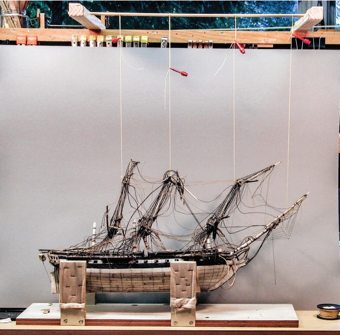
Jewelers’ gravers — palm-held, finger- and wrist-controlled microchisels — are efficient for freehand cutting on model makers’ machine lathes. Held against a tool rest or firmly in hand, well-honed gravers cut brass, wood, and ivory sweetly. They come in many shapes and can be ground on the Tormek to others, if necessary.
Although it’s said that one can’t have too many clamps, I’ve found it’s more important to have a variety of them in many sizes. Bar clamps and C-clamps are indispensable and come in many sizes and styles. I have four ancient 6-inch steel bar clamps that were my father’s. With threaded adjustment, they are tough, powerful, and precise. But the bars on many modern bar clamps are so bendy that great pressure on them distorts their direction of effort. One-hand, quick-release bar clamps are handy, but also lack
27
Gallows. Broken spars are suspended by strings from a dowel above the bench. Strings are easily adjusted with the red, retractable-hook test clips. The idea is to raise one part at a time while gradually organizing the rigging. Notice the simplified adjustable cradle.


power. I use metal C-clamps ranging in size from about ⅝ to 6 inches. They are strong and easy to set. My favorites may be the tiny Preac jobs made of aluminum with nylon screws. Hand-powered spring clamps are generally powerful and versatile. Perhaps the most basic are the old-fashioned spring-activated wooden clothespins. I use the standard and two smaller sizes. They are lightweight and inexpensive and can be easily altered to any shape needed. Larger, stronger, metal spring clamps are terrific for fast, direct pressure. The traditional wooden, handscrew clamps used by furniture makers may be the most powerful of all because, with their double-screw mechanism, they can exert tremendous leverage to close seams.
Ingenuity and improvisation are important elements for successful clamping. They can generate clever blocking so pressure is exerted where it’s needed. Jaws on some modern clamps can be adjusted to push things apart rather than pull them together. It’s also smart to keep a selection of smaller and larger wooden wedges handy. They are valuable for exerting local force where a clamp might not fit.
I adopted an item particularly useful for model rigging from the electrician’s tool kit. This is the retractable-hook test clip. With a spring-loaded plunger, a small hook can be opened and closed to secure a line temporarily without having to tie a knot. This is terrific for maintaining tension on deadeye lanyards, for instance, until all are installed and a mast is where you want it. More powerful than they look, they are available in a host of sizes, styles, and colors from sites on the Internet.
Sometimes, while working on display cases, large pieces of glass must be manipulated. This can be especially dicey when disassembling old cases that may be falling apart. Many outfits make manual pump-action suction cups that reduce the fear of handling glass. They provide a firm grip and let you control the glass without holding it by what may be sharp edges.
Sitting on my tool shelf is a jam jar of those double-ended dental picks — the kind hygienists seem to wield medievally. I only use one or two occasionally. I always think dental tools, like burrs and polishing brushes, will be more useful for modeling than they turn out to be.
Orderliness
Cluttered workshops are visually engaging, no doubt. But such environments make me claustrophobic and unproductive. There is a place in my shop for every item. Every week or three, I put everything away and sweep up. Every few months I vacuum exposed surfaces. About once a year I do a thorough cleaning. All spaces and items are vacuumed or cleaned; nothing goes untouched. I do it in the spring or fall, with door and windows wide. The effort takes eight or ten hours, but there are benefits. The first is a pragmatic review of all my tools and materials that refreshes my memory, reinvigorates my creativity, and reacquaints me with old friends. It helps me cull stuff I’ll never really need “someday.” The second is aesthetic. A shop layered with dust becomes monochromatic; removing the dust

28
Retractable-hook test clips. These are 2¼- and 1½-inch examples. The red one to the left is being held open to expose the copper hook.
Five retractable-hook test clips (and a small squeeze clamp) hold various lines while rigging is being adjusted in the top of a prsioner-of-war model.
Stripwood tray. Vertical dividers hot-glued to a foamcore base form eight slots for organizing stripwood. Sticks below the foamcore provide rigidity.
brings the colors and depth back to everything — a Kodak moment. It is a healthier environment for caring for ship models.
A few easily made items help reduce clutter. One is a piece of foamcore about 1 foot square partitioned with wood battens hot-glued to it. The device organizes stripwoods of different sizes and species for a given job. A ¾-inch-thick pine board with troughs ripped out on the table saw does the same job for metal rods and tubes.6 A 4-inch wooden cube with 9/16-inch holes bored into the top manages two dozen pairs of pliers.
Then there is the phenomenon I call workbench creep. I am right-handed, so I inevitably put tools down immediately to the right of the spot where I am working. The result is that each tool lands a bit to the left of the previously used tool, and the working space creeps incrementally leftward until I am at the end of the bench or up against something. Then it’s time to tidy up.
Work comfortably. I use two chairs and two stools; all are set at different heights so I can easily change positions for different tasks and so my posture doesn’t fossilize. I also stand a lot (but not always, like some modelers). If a model is tall, be prepared to put it on the
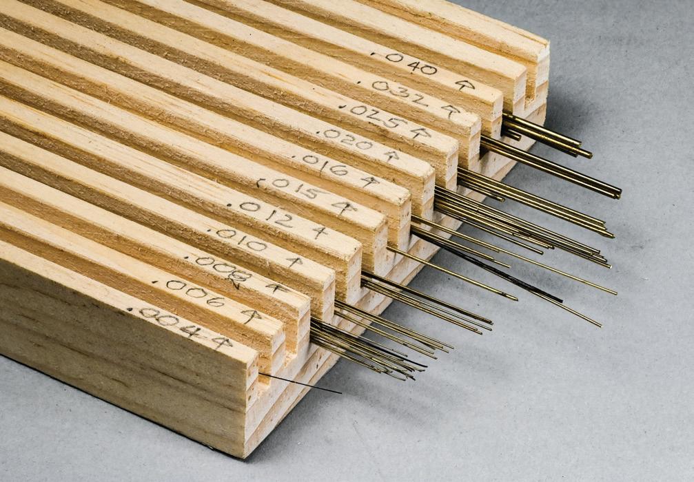
floor. Sometimes I must work on a step ladder, which is awkward but better than working with my hands above shoulder level.
Keep all your fingers in the original digital world. We all understand that dangers lurk in any workshop. Without proselytizing at length, I will share some things I keep in mind. I keep tools sharp and clean, so they behave predictably. No matter which cutting tool I’m using, I keep my eyes on the blade where it enters the workpiece, and I try to never let my fingers interrupt that view. I try to focus on a power tool’s immediate job, so my thoughts don’t wander to what’s for dinner or if that noise outside is the UPS man. While it’s occasionally necessary, I avoid having two power tools run at the same time — unless one is the vacuum. A continuously running 6-inch-square equipment-cooling fan provides white noise that isolates me from startling distractions; its direction can be adjusted to provide airflow and ventilation where I need it. I am attentive to the sounds of tools and materials interacting. When the band saw makes an erratic, fluttering noise, I have learned the blade is about to break; I stop the saw immediately, find the crack, and change the blade. I remove chuck keys from chucks, so they won’t fly out and hit me in the face when the tool is turned on. In fifty years, I have never done any three-dimensional work — with power tools or otherwise — after having a drop of an alcoholic beverage on a given day, ever.
The Department of Cheap Insurance
The threat of accidentally damaging a model lurks always. But several ways to minimize accidents are easy and inexpensive. Their success depends on consistent application. Here are some suggestions:
The first spar to get broken on most square-rigger models is the bowsprit. Next is an upper segment of the tallest mast. Then it’s the main yard. Do I need to say that these are the model’s extremities? Rigging associated with these spars is also the first to go. To prevent

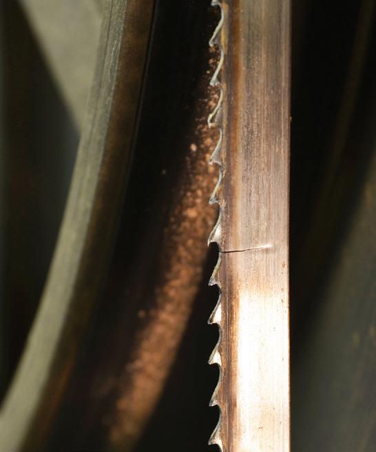
29
Rod storage. A pine board with slots ripped on the table saw manages brass rod, tubing, and other similar materials. This rack is 24 inches long and just wide enough to fit with several others in a partitioned drawer.
A 4-inch cherry cube bored to hold twenty-four pliers, cutters, and similar tools.
The tear in the band saw blade (arrow) was detected by the change in sound the blade made as it cut through a workpiece. The blade was changed before it broke. The tear was not at the weld.
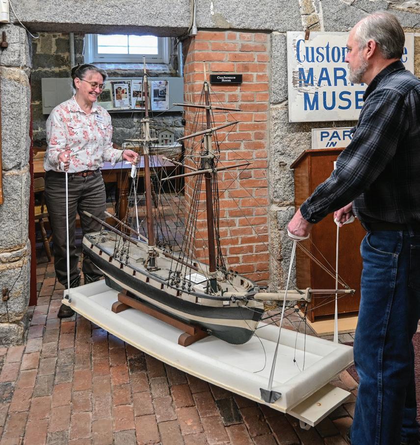
Joan Whitlow, director of the Custom House
a lot of this, make both working bases and final display bases large enough to extend under the full length and breadth of a model, including its rig. This eliminates the temptation to set items (like tools or cocktails) within a model’s perimeter, and thus, the possibility of breaking a bowsprit, yard, or worse when lifting the item suddenly. Large bases also protect the model when it’s being moved or stored.
When working with another person on opposite sides of a model, agree on how you will pass tools and parts to each other. Avoid lifting objects over the model or through its rigging. Reach around the model’s ends, or, if it spans a space between two benches, pass under the model.
Know before you pick up a model where you will put it down and have that space prepared. Keep the model level. Until you prove otherwise, always assume fullhull models are loose in their cradles and half-models are not attached to their backboards. Doing so may prevent models from taking flight.
When lifting a model with two people, choreograph the action, especially if the model is being moved into or out of a case or crate. One person should be in charge and should call each step of the move. I have watched too many topgallant masts shatter when one person moved while the other paused. If there are more than two people, the potential for confusion will be even greater because each will want to be the boss. Avoid having extra people who just want to help.
A highlight of my career was working with Dana Wegner, curator of ship models for the U.S. Navy at the David Taylor Model Basin in Bethesda, Maryland. From 1990, we sat three times as judges for the Mariners’ Museum quinquennial Scale Ship Model Competition and Exhibition. Wegner explained that, in his Navy workplace, there is an established way to move models. One way isn’t better than another; rather, in the heat of labors, a predictable system of moves is safer for the models because everyone knows what to expect,7 like traffic at a roundabout. Wegner’s rule is to
carry or transport models, even if encased, bow first. If they must be carried athwartship — as in a vehicle or on a cart — always have the bow to the right. If they must be rotated, always rotate the same way, clockwise or anticlockwise. Some people may call this sort of slavishness superstition; I call it cheap insurance.
Now, on your bench is a model, and you need to work on its other side. Contrary to the previous suggestion, when turning it, always turn it so the same end — bow or stern — crosses in front of you. Doing so alternates clockwise and anticlockwise. This means you will always be dodging the same projection — say the bowsprit — at one end and the other end will always be avoiding the same obstacles on your bench.
Occasionally a tall model must be moved through low spaces or doorways. Bending over to carry the model near the floor is uncomfortable and can place your face in the rigging. To avoid this, build a simple tray that is as long as the model. To each end of the tray, secure a rope and tie bowlines in its ends. Place the model on the tray. Now the model can be lifted by the ropes and moved easily.
Always protect lower edges and corners of baseboards, cases, and half-model backboards by setting them on sticks on your table or workbench. This prevents scratches and provides room for fingers later, when lifting the items.
Shelves protruding over workbenches can negatively impact upward projections on a model when it is casually pushed to the rear of the bench. To avoid this, tack a rail to the bench that limits how far back the model can go.
A few tricks will help prevent the loss of small parts. First, always carry them in a container, not just in your hand. Likewise, work them from one container to another on the workbench, not from one open heap to another. Second, to avoid losing parts on the floor, install a rail along the edge of the workbench and work inboard of the rail as far as comfort will allow. Third, vacuum frequently the area around your bench and
30
Maritime Museum in Newburyport, Massachusetts, and her husband Scott move a large model of a mid-nineteenth-century topsail schooner named Sylph through a low doorway on a heavy foamcore tray fitted with twill tape lifting straps.
chair to simplify retrieval of tiny parts that find their way to the floor; it’s easier finding small parts on a bare floor than in dusty mess. Fourth, using a jeweler’s saw requires both hands, so there is no way to grasp small cut-offs. They habitually end up in the Belt of Missing Parts. If a hole pierces the part, tether it to the bench with a length of light-weight wire. Fifth, place small parts on a sheet of white paper so they don’t disappear into bench clutter.
Glass Cases and Lead Sickness
There are two kinds of model collectors. The first prefers protecting models by displaying them in cases. The second prefers displaying models without cases to avoid having large glass boxes, which are conspicuously architectural and clutter rooms. To be professional, I always recommend that collectors, whether of a single model or a large fleet, use cases. But I sympathize with those who don’t want them. Honestly? It won’t surprise you to learn that I prefer having nothing between ship models and me.
Ship models have been exhibited successfully in all sorts of cases. It is not my intention to present or support a particular design for display cases because individual requirements depend on too many factors. These include the abilities of case makers, the design and physical environments where cases are to live, and so forth. However, I do recommend a few things. First, good case designs favor and do not visually overpower the nature of the models within. Second, good cases are secure on their bases, yet are easy to either open or remove. Third, healthy cases are not airtight, as we will see.
Bear in mind that cased models, while protected from physical injury, are not necessarily out of harm’s way. Many cases are constructed to be airtight in the belief that doing so will better protect a model. But Dana Wegner’s revelatory 1998 article “Lead Corrosion in Exhibition Ship Models”8 tells us that malicious
forces work within sealed cases. It seems that virtually all materials used in ship modeling outgas. It’s not surprising that paints, glues, and other chemical products do this. It’s unnerving, though, to learn that wood is among the worst culprits. (Basswood ranks in the most offensive category.) Materials used to make cases also outgas. The worst offenders are plexiglass and related acrylics. (However, real glass is stable and does not outgas.) The offensive outgassing is acetic acid that intensifies enough to attack the most basic element in the closed environment, and this is usually lead. Lead was used regularly for anchors, top platforms, and trestletree-crosstree units on folk-art and, less often, on prisoner-of-war models. It was also used for blocks, deadeyes, chainplates, guns, and other fittings. It is prevalent in soft solder. Lead’s ease of use is offset by its susceptibility to outgassing in a condition called “lead corrosion” or “lead sickness.”
Lead sickness is like an ailing canary in a coal mine: If you see it, there is a problem with the atmosphere. The malady’s primary symptom is a powdery white bloom or exfoliation on surfaces of lead fittings. In advanced states, white flakes fall from fittings to form snowy footprints on a model’s deck or baseboard. Eventually, lead fittings will be consumed altogether and will collapse; soft-soldered joints will fail.
There is a two-step solution to reducing the outgassing problem. The first is to ensure that air can circulate in and out of a case. In high-end museum installations this is done with systems of air-circulating pumps and filters. But Wegner has demonstrated that passive air exchange works satisfactorily. Case design should incorporate construction details or small fittings that will allow air to flow in and out. (Two 1-inch-diameter openings in a baseboard of a large model are sufficient. The holes can be under the model and screened to prevent access for unwanted creatures.) The second is to not use plexiglass or related materials for a case. Use real glass. It may be heavier and somewhat more fragile, but it won’t destroy models all by itself. Of course, the
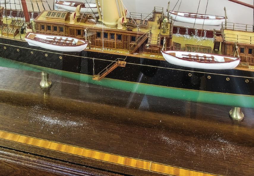
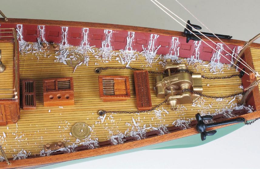
31
Advanced lead sickness. The highly acidic environment in this model’s sealed case denigrated the condition of the two white boats that were cast of lead or a high-lead-content alloy. Flaking lead has left snow-like debris on the model’s baseboard.
The same model’s bulwark stanchions were so slim that they are almost wholly consumed. This modern imported model at about 1:96 scale represents the 1891 American single-screw steam yacht Corsair II

best way to avoid lead sickness in new models is to not use lead at all.
The best treatment I learned for lead sickness was from Museum of Fines Arts conservators in 1989. First, the white powder is scraped away with a blade or dental scaler until the lead is silvery bright. This must be done with good ventilation to avoid breathing the toxic dust. Then B-72 (more about this in Sticky Stuff) is brushed on the lead, and the fitting is “in-painted,” or touched up, with acrylics to the appropriate color. The idea is that the B-72 forms a barrier to whatever was attacking the lead. It was understood that the B-72 works better than any paint but was still an imperfect foil; it hinders but does not prevent reoccurrence.
Different folks swear by their own methods for cleaning glass cases. Some use commercial cleaners like Windex. Some use a solution of 3 percent acetic acid or of 50 percent isopropyl alcohol in water. Some use soap or vinegar and water. Some use moisture from their breath. They wipe with cotton cloths, paper towels, newspapers, or squeegees. Microfiber cloth is handy until it absorbs what it has removed, then it must be washed. With care, they all work. I use what comes to hand.
Remounting
Models that need major repairs may also need work on their displays. Displays range from simple baseboards to complex cases and cabinets. A display might just have a scratch in its finish, or it might be shattered entirely, but it’s likely somewhere between. Clients may want a model moved to a new display to meet installation requirements. Or they might want a simpler display. Clients facing major expense to have an uncased model repaired frequently consider a case. Clients and I spend generally as much time discussing a display as we do the model that will be fitted to it.
Years ago, case making was a service I offered. But it requires different tools and materials, and a separate mindset. In time, I learned to avoid aggravation by sub-
contracting the work to specialists, and this has paid off. Now, knowing my subcontractors’ skills, I plan a display with a client. Later, the case is delivered, ready for me to install the model.
Models require support. This might be a pair of cradles (which are harder to fit to a hull than you think they ought to be), a pair of pedestals, a set of keel blocks and bilge poppets, or something else. Of course, it’s a good idea to preserve the intent of the original modelwright, especially if the model is old. But this isn’t always possible. Some collectors and institutions feel that a mounting system is not a critical part of a model. They might want all their models’ displays to be uniform, even if early display components are sacrificed. Decisions about these things must be worked out.
Many display components are more or less generic. Nonetheless, some modelers — Horace Boucher, Donald McNarry, and Erik A. R. Ronnberg, Jr., come to mind — strove to identify their work with individually consistent display designs. In such instances, it seems even more appropriate to honor their efforts.
Although I no longer make cases, I make support components and install models in new displays. Always fussy, installation requires careful measuring and a good eye for where a model’s volume fits inside a vitrine, or glass cover.
Be sure that a model is firmly attached to its supports. Eliminate all motion that may have developed over the years. If a model wobbles on keel pedestals, try adding shims so the keel-to-hull joint is not stressed. If it rocks side to side in cradles, shim the appropriate sides to prevent chafe to the hull’s finish and to keep the model properly vertical.
Sometimes holes for mounting screws or bolts in displays or models are not vertical. Perhaps they were bored that way or they have become worn with multiple remountings of a model. The result is that it may be difficult to remount a model so it is properly vertical, especially when viewing it from the ends. There is a simple cure: the bent-screw technique. If the model
32
The upper tool, a sharp-edged, hooked scaler of the sort used to scrape teeth clean, is excellent for scraping lead exfoliation off fittings. The lower tool is useful for scraping in tight places; see Case Study 5, USS Constitution
A B E D C

tilts to one side with the screws set as snuggly as they should go, note the angle of the tilt. Then mark the screw’s head on the side toward the tilt. Remove the screw. With pliers or in a vice, bend the screw at the point where it enters the bottom of the keel. The angle of the bend should be the same as the tilt, and the bend should be away from the tilt. When the screw is reinserted, the model will wobble side to side until the screw is seated, then it should be vertical. Adjustments may be required, but you get the idea.
Dehydration
Perhaps the most important thing to understand about wood as a material for making objects from houses to ship models is that it starts wet. The lumber industry’s colloquial standard period of time for letting wood dry in air so it will be relatively stable for working is one year for every 1 inch of thickness. But this is just the beginning.
The National Park Service, in The Museum Handbook, Part I Museum Collections, reports that, although figures vary by species, air-dried and kiln-dried woods dehydrate until they reach moisture contents of 10 to 25 percent and about 7 percent, respectively. While drying, wood changes size and shape. Changes in size are mostly across the grain and, averaging about 8 percent (or about ½ inch across a 6-inch-wide board), are conspicuous. Changes along the grain, or in length,
however, average only about 0.1 percent and are inconspicuous. In both cases, the change is shrinkage. Wood eventually reaches an “equilibrium with its environment…as long as the [relative humidity] remains constant.” Later, the wood can continue to shrink if the relative humidity drops more or swell if it increases.9
Shape changes — warping, dishing, diamonding, twisting, and so forth — depend on from where in a log a piece of wood was cut. These changes are predicable in larger pieces of wood where the end grain can be seen and evaluated, but they are more difficult to predict in smaller pieces, like stripwood.
The best method for keeping wood where you want it is to house it in a stable environment where there are minimal or, ideally, no fluctuations in humidity. Temperature is also a factor because it affects humidity.10 Humidity parameters are recommended by the National Park Service:
The ideal relative humidity level in most areas of the [United States] for wooden objects is 50% plus or minus 5%. In dry climates, such as the southwest, 35% to 40% is acceptable. These levels are difficult to achieve in very dry climates because the moisture content in wood drops rapidly below 35% [relative humidity], causing splits. Below 30% the glue may desiccate, joints may loosen, and finishes will become brittle. Along the coast, 55% to 60% is acceptable, but above 70% mold and insects may become problems. When humidity is this high, glue may weaken, finishes may bloom, hardware will corrode, and wood fibers will swell exces-
The bent-screw technique. At A, the model is properly mounted with holes in the hull and in the display vertical. At B, the hole in the keel is off center to the right, so the model tilts to the left when the screw is inserted. At C, the hole in the keel is centered, but the hole in the display is not vertical, so the model tilts to the left. At D, The screw has been bent to the right to correct for the misaligned hole in the hull. At E, the screw has also been bent to the right to correct for the misaligned hole in the display.
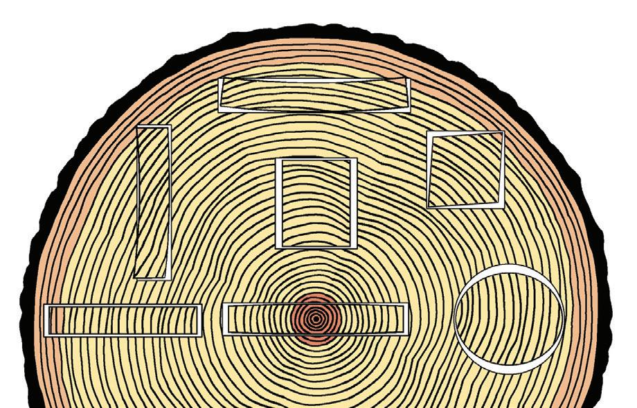
Typical wood shrinkage. How lumber cut from various parts of a log generally changes shape during dehydration. (Adapted from “Appendix N, Curatorial Care of Wooden Objects (2002),” The Museum Handbook, Part I: Museum Collections (Washington, D.C.: National Park Service, Museum Management Program, n.d.), p. N:16)
33


Focus on Dehydration
A. White paint has separated from the pine substrate on a 46inch, 1:32-scale decorative half-model of the 1893 American racing schooner Corona
B. This half-model was constructed with alternating lifts of different species of wood that dehydrated at different rates. The result is that the model looks stepped. Builder’s half-model of the 1874 brig J. F. Merry. (Photograph courtesy Maine Maritime Museum)
C. The wooden funnel has shrunk inside the pinned-on brass band to which are shackled the upper ends of the funnel guys. Notice the gap (arrows) on the aft side. Detail of the model of Rangitiki.
D. A model hull about 12 inches deep from deck to keel had a single-piece, sawn-brass sternpost, propeller aperture, rudder, and keel unit. The wood shrank, the brass didn't. There is a noticeable gap (arrow) between the bottom of the wooden hull and the brass frame. Detail of a 116-inch, 1:48-scale builder’s model of a proposed but unnamed single-screw transatlantic liner of about 1880.
E and F. If you don’t believe the wood of a model’s hull can shrink to the point of self destruction, this may convince you.
The bulwarks of this large, solid-hull model were integrally carved from a laminated hull block. Ends of the superstructure components, which also had their grain running fore and aft, were covered wvith athwartship panels so finishes would not be applied to end grain. The wood of the hull and superstructure shrank across its grain, but the athwartship panels did not shrink in their lengths. The result was that the panels blew out the bulwarks, as shown. This was corrected by removing the panels, drawing in and gluing the sprung bulwarks, then shortening and reinstalling the panels. Details of the 164-inch, 1:48-scale builder’s model of the Orient Line’s beautiful 1929 twin-screw passenger liner Orontes G. This deckhouse was a single block of softwood with panels mitered into its forward and after ends so all painted finishes are on side grain. Despite the two screws securing it to the deck, the main block has shrunk across its grain, but the panels have not shrunk in their lengths, so they have been forced out of the main block at the miters (arrows). The model was about eighty years old when this image was made. The cure was to shorten and reinstall the panels. Detail from the model of Sicilia.


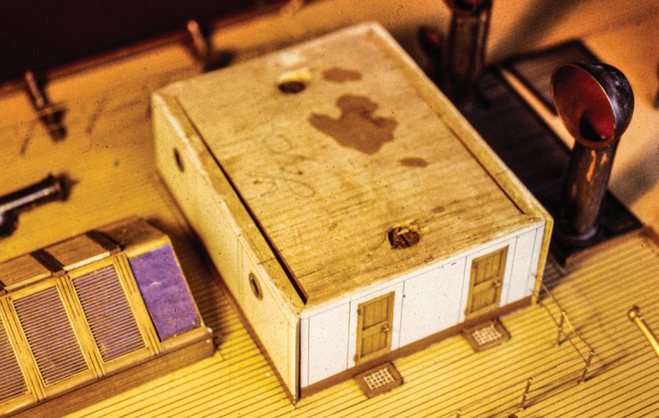
34
A B E F G D C
sively…. Avoid temporarily heating, air conditioning, or humidifying spaces that house wooden objects. Do not turn off heat or air conditioning at night.11
Relative humidity is difficult to maintain in private or non-institutional settings. I have recommended to a client in an extremely arid region that he place humidifiers near his models, but even when operating full time, they didn’t do enough. I suspect homes in climates that require year-round air conditioning are the most stable.
Dehydration symptoms are easy to spot. A 5½foot model steamship I maintained was built in 1930 of laminated wooden lifts. When I first saw it in 1983, it was more than fifty years old. The lifts had dehydrated to the point that glue lines between them were visible as hairlines, but paint over the seams had not broken. I thought the model had shrunk as much as it could; it had probably achieved equilibrium. Now, in its new, extremely dry home, the humidity was measured at 10 percent in winter. Shrinkage renewed; only four years later, the seams had opened visibly, and metallic parts, which stay the same in size, were separating from wooden parts, which had changed.
Wooden spars shrink in diameter. Bands with rigging eyes, if not pinned to the spars or set against shoulders, will slide on spars; rigging tension is compromised and difficult to correct. A mast that was snug in its step may shrink and settle, thus loosening shrouds and other rigging.
Paint has difficulty sticking to improperly primed wooden hulls that have shrunk. It will chip and fall away. Repairing an immediate area of loss may not keep adjacent paint from falling off the substrate later. The least treatment is usually best, especially if conditions can be stabilized.
Cleaning
Nothing will teach me — or you — more about a model than the cleaning process. To clean things well,
you must really look at them. Their condition and construction come into focus quickly. Most old ship models need cleaning. An initial look will reveal if a model is dusty or if it is dusty and dirty. By dirty, I mean that the model is coated with something that can’t be brushed away.
If a model is reasonably large and robust, I start with an artist’s soft, 1-inch nylon brush to learn if dust can be removed easily. I stroke lightly but, if that is inadequate, I work harder. After testing rigging for strength, I run a smaller brush carefully along each line. If it’s a big job or if there is a lot of dust, I work either with a fan to blow away brush-loosened dust or I brush dust directly into a vacuum nozzle. When vacuuming, it’s good to install a clean filter so parts can be retrieved if they get sucked in. Although some vacuums are made for small items, like computer keyboards, I find them inefficient. Canned air marketed for dusting may be okay to use on rugged models, but, on fragile ones, it tends to break rigging and to blow small items all the way to the Belt of Missing Parts.
Smaller and more fragile models receive about the same treatments as larger ones, but they require smaller tools, a much lighter touch, and, ironically, more time per square inch.
Being systematic keeps track of progress, especially when it’s hard to tell what has been cleaned and what hasn’t. I begin at the bow on the starboard side, work to and around the stern, then forward on the port side, always working right to left because I am righthanded. I continue at the top of masting and work down. If a model has a prominent superstructure, like a battleship’s, I work from the top down, then around the hull. If I have the good fortune to have a colleague, we work from bow to stern on opposite sides of the model.
Keep a container handy to receive everything that separates from the model. Items dropped on the bench stand a reasonable chance of being swept to the floor and discovered with an audible crunch. If there is any
35


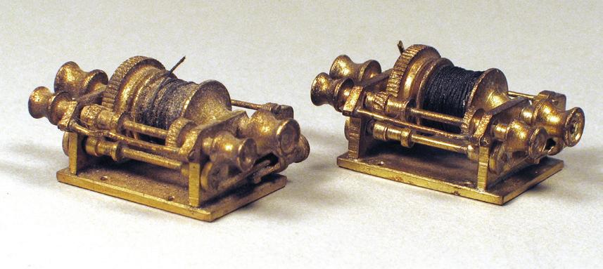
doubt about remembering where a part came from, bag and tag it.
While dusting, I consider possible cleaning processes and make tests. Models with larger exposed surface areas, like half-models, may clean up quickly with a cloth damp with water. If necessary, a weak solution of detergent in water may be used. Some projects require more aggressive cleansers, but they should be tested thoroughly and inconspicuously. In cases using anything except plain water, surfaces should be rinsed after cleaning. Dry damp surfaces quickly to prevent moisture absorption.
Cleaning can be done with several kinds of applicators. I use soft cotton cloths, paper towels and facial tissues, sponges, and even, occasionally, old worn toothbrushes. Cotton balls and swabs are indispensable.
No matter the temptation, avoid drastic full-immersion cleaning methods, even if they do save many hours. British ship modeler and author Harold A. Underhill wrote, classically, that when the dust got too bad on a model, he put it on the roof outside his office window “for five or six hours of a pouring wet day — [he] always picked a good one.” After letting it drain over his sink, the model was “returned to its shelf…good as new.”12 I recently heard of someone cleaning a model while he was in his swimming pool (chlorine can’t be good), and I once cleaned a 39-inch toylike destroyer model with a garden hose on my deck. Really? I don’t do these things, now.
Dirt and grime settle mostly on a model’s upper surfaces, but there is a formidable exception that also coats undersides of everything. I think of it as nicotine and tars from exhalations of tobacco products. Conservator Mimi Leveque calls it “airborne particulate matter.”13 Either way, it is evil. It is characterized by a revolting brownish-yellowish residue on wipes and swabs and, when dampened, smells like wet ashtrays. Removal requires many applications. I usually use detergent in water, then rinse.
Modelers frequently sheathe hull bottoms with individual copper plates. Besides being hard to do well, the practice leads to maintenance nightmares. Gen-
erally, the plates are attached with contact cement or two-sided tape. Even if these don’t fail, there is the chance that the wooden substrate under the copper will shrink, thus wrinkling the copper or causing it to peel. When it comes to cleaning copper, my advice is to do as little as possible. Any action must be performed in the direction of the lapped plates. That is, if the plates are laid from the bottom up (like shingles on a house), wiping must be from the top down, off the laps’ edges. Otherwise, the copper and cleaning applicator will tear at each other destructively. If any liquid is used to clean, great care must be taken to not let it seep under the copper.
Ultrasonic cleaners are indispensable for cleaning dirt, oil, the detritus from soft soldering, loose paint, and other grunge from metallic and other nonporous parts that are separable from a model. An ultrasonic cleaner has a reservoir filled with a solution of water and perhaps a drop or two of detergent. The device vibrates the water rapidly. A five-minute immersion usually suffices. The devices are available in many capacities from jewelry supply houses. I have the smallest from Gesswein; it holds a pint of water.
The holds of plank-on-frame models or hollowed solid-hull models are generally inaccessible for cleaning. However, it is occasionally necessary, for academic reasons, to go below to investigate and fetch whatever is there. Assuming you can’t get your arm and hand inside, the easiest cleaning tool is a pliable plastic tube attached to a vacuum pump equipped with a filtered receptacle. I work the tube everywhere I can; I also use a magnet and tweezers.
The Enzyme Technique and The Amazing Cotton Swab
Most models will benefit from what is called the “enzyme technique.” This is euphemistic for spit polishing. The process is simple. Moisten a cotton swab with saliva, then wipe the model’s deck with the swab. Do an
36
Tobacco residue. A paper towel moistened with water and mild detergent removed this airborne tobacco residue from a half-model in a single wipe. From a contemporary, 46-inch, 1:32-scale, decorative half-model of the 1893 America’s Cup defender Vigilant
A 1-pint ultrasonic cleaner.
The 1:96-scale cargo winch on the left has not been cleaned ultrasonically; its mate to the right has.
area about 1-inch square at a time. If space permits, use the side of the swab and roll it on the surface to maximize swab usage. If the swab comes up black, repeat the application with new swabs until one comes up clean. For tenacious grime, moisten an area with a wet swab, then let it sit for a minute or two to work before wiping. To keep your workspace looking professional, toss used swabs into the trash immediately; don’t let them accumulate. You don’t want to put a dirty one in your mouth, but it happens.
Clients may be taken aback when I demonstrate the enzyme technique. However, I learned it in 1989 from conservators at the Museum of Fine Arts. It isn’t as bad as it sounds. Enzymes in saliva are the first agents in food digestion, so they have some power. They lose effectiveness quickly and are neutral on the pH scale. After a sip of acidic coffee or tea, saliva becomes neutral again after a swallow or two. The technique leaves little residue; some conservators want surfaces rinsed with distilled water after using the enzyme technique, but others do not. Your mouth will not run dry. One observer commented that I was “licking the models.”
Now, the enzyme technique wholly depends on the lowly cotton swab (or cotton “bud” in British English) so it deserves comment. In the 1920s, a Polish-American named Leo Gerstenzang wrapped the end of a toothpick with cotton. He founded the Leo Gerstenzang Infant Novelty Company, and the product morphed through several names until it finally became Q-tips. “Q” stands for Quality.14
Use only 100-percent cotton products because they are softer, won’t scratch, and are far more absorbent than synthetics. I use three types of commercially available swabs. The first is the familiar double-tipped variety that is sold in drug stores and supermarkets. The cotton tips are bulbous. They come hundreds to the pack and have 3-inch paper or plastic sticks. I prefer paper sticks because they can bend to get into awkward spots. The second type is the single-ended swab
on a 6-inch wooden stick. Longer sticks are great for reaching across models with dense rigging and under overhanging decks. The third type is also on a 6-inch wooden stick, but its end tapers to a finer point. These get into corners the bulbous tips can’t. Both 6-inch types come in hundred-count packets, ten packets to a box; I order them by the ten-box carton from Solon or Fisher Scientific.
Drug store double-ended swabs are by far the most economical. The 6-inch regular-tipped swabs are next, and 6-inch tapered-tip swabs are most expensive. Despite costing more than eight times as much per tip (at this writing) as shorter, double-tipped swabs, the longer, taper-tip type will quickly become your swab of choice for all except the most open areas. You might think that hundreds of wooden 6-inch swab sticks might be useful after their business ends are soiled; some folks may consider them a resource too vast to ignore. Not me: I pitch them.
Many conservators roll their own swabs. The only advantage I see to this labor is they can be sized and shaped to fit any application. I roll my own only when I need to reach tiny spaces on small models. I sharpen the end of a 6-inch wooden stick, pinch a tuft off a cotton ball, lick the stick, apply it to the tuft, and spin it between my fingers: Presto! It won’t last long, but it’ll do the trick. Pull off and toss the cotton; re-use the stick.
Raw wood and flat finishes; sharp corners and wire ends; belaying pin bottoms; the edges of cracked paint; and countless other culprits lurk to rip fibers from cotton swabs. I call these annoying strands “fuzzies.” Nothing erodes the sense of compelling impression in close-up model photography faster than fuzzies. They’re difficult to see before they dry, so be sure to review recently swabbed areas. Remove fuzzies — you’ll need fine tweezers — the moment you spot them because you will never remember them all, later. You won’t see them again until the model is cased, then it’ll be too late. If you find fuzzies already on a model, they are
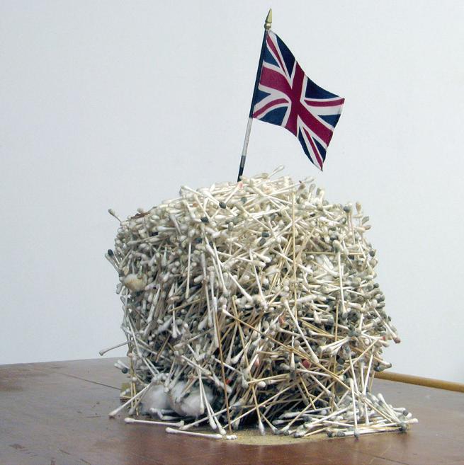
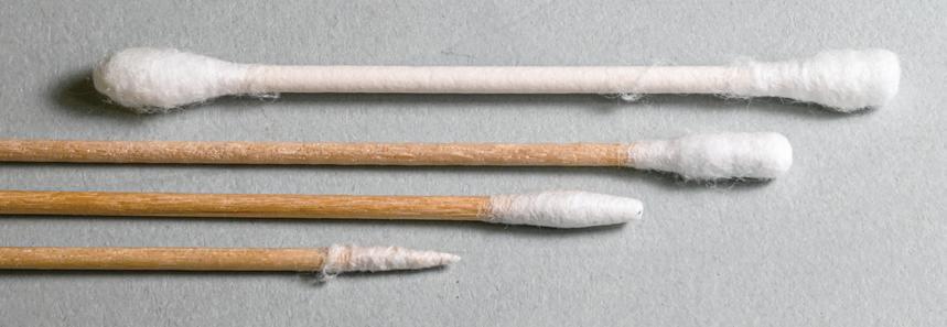

37
Mount Ever-Swab. This accreted mass of used cotton swabs and balls was turned out of a trash basket like a muffin from a tin. They cleaned the model of Princess Royal
Four swab types: standard pharmacy double-ended (A); long, wooden-sticked (B); long wooden-sticked fine tip (C); and fine-pointed hand-rolled (D).
A commercial swab next to a sharply pointed hand-rolled swab at gunports on a small prisoner-of-war model. See Case Study 7.
A B C D

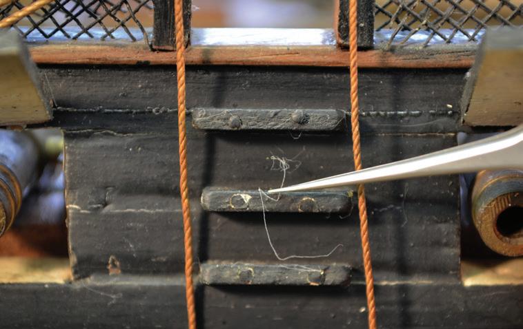

evidence that another hand has cleaned it before; you must finish his work.
It’s irksome to swab areas inside bulwarks. Those on the model’s near side are hard to see because of tumblehome, rigging, cannon, and boats. And those on the far side, while physically close, are frustratingly hard to reach because of a dense hedge of deck structures, guns, other fittings, and rigging. I can use mirrors successfully for examinations, but I am hopeless at using them for actual work, like dentists. So, when swabbing the inside of the near bulwark, I work by touch while watching the far bulwark to understand where I’m going. To help concentrate on reaching small, remote spots, I repeat the mantra “If I can see it, I can clean it.”
Tight spots are challenges. Visualize the deck inside the fife rail on a sailing ship model. Among the pumps, deck blocks, belaying pins, coiled lines, and friable rigging, tiny areas will be visible, but shadowy. Use your sharp-pointed, self-rolled swabs. It’s worth the effort to clean the dim corners and see the bright deck peek through the congestion if only to hear clients marvel, “How the heck did you get in there?” Don’t be surprised to find such spots are dirtier than the model’s more accessible surfaces. This is further evidence, like remaindered fuzzies, that someone less dedicated preceded you. Don’t let your successor have the same satisfaction.
On liners and modern warships, there are many overhanging decks supported at the sides by railings, bulwarks, and stanchions that hinder access to the deck sheltered by the overhang. To clean such inaccessible areas, I employ a sort of mega-swab. Moisten an entire cotton ball with saliva, place it on the deck, and push and pull it longitudinally with a stick from the ends. Cotton balls use a lot of saliva, but you won’t need many of them. Cotton balls also expedite cleaning large, open deck expanses.
Use your idle hand to brace loose, but undetachable, parts such as yards pivoting on their cranes and anchors hanging from their catheads. Put a fingertip
behind each block you clean — you must swab them all. The falls of boats hanging from davits chafe on unfaired sheave holes in their davits; so be sure to steady the boats.
Cannon on models of sailing warships present their own problems. Fragile gun tackles restrict access to axles, trucks, and the deck below them. This is another place to utilize the smallest home-rolled swabs. Consider that it may be easiest to get swabs to the cannon from outboard, through the gunports. Cannon with open-muzzled barrels can be steadied by holding a stick or drill bit inserted into the bore.
We all know that removing pictures that have been hanging on the wall for years can leave unfaded rectangles. This can happen with moveable objects on a model’s decks. The unfaded areas are called “light shadows;” they can’t be cleaned away. Be sure to replace the objects that caused them in the right places.
Often your swabbing hand needs to be inside a model’s rigging to get the best working angle. Inserting and removing your hand for each swab is dicey. So, use your free hand to remove used swabs from and offer new swabs to the hand that remains inside. By the way, when working in and around rigging, remove wristwatches, bracelets, and large rings or eventually they will snag something you can’t repair easily. This is a rider on your cheap insurance policy.
The truth about how well you cleaned the first side of a model will be revealed when you start the other side. Large and small areas that were missed announce themselves, and they need to be attended to. Don’t forget the fuzzies.
Sticky Stuff
I am frequently asked, “What glue do you use?” The answer: “Several.” Let’s look. Hide and fish glues have been around for centuries. They are rendered from parts of various animals. These glues are water soluble, reversible (so they can be undone), noninvasive (so
38
An obvious fuzzy snagged by a pinhead on each of two adjacent steps of the accommodation ladder.
Removing the fuzzy with sharp MM tweezers.
The largest fuzzy is gone, but nearly sub-visual fuzzies remain, as indicated by the white arrows. Notice that these are nearly invisible in the top and middle images.
they don’t attack the composition of what they hold together), and traditional. Hide glue comes as flakes that must be dissolved in water and worked hot, but it sets quickly. Fish glue comes as a viscous liquid, can be thinned with water, works at room temperature, and sets more slowly. Both dry hard, shiny, and brown. When set, they are indistinguishable, at least to me, but are identifiable from other glues on old models because they fluoresce under ultraviolet light. These glues are good for wood, paper, fiber, and other porous materials. Hardened animal glues can be softened with a hot knife edge15 or with acetone. I use fish glue from Lee Valley Tools.
Polyvinyl acetate (PVA), or white, glues are water soluble until they set, suitable for porous materials, and easy to use. They have great initial strength, but they can fail in time. Old PVA is grayish. It becomes rubbery but hard and is difficult to carve away. It can be softened with isopropyl alcohol.16 I use Elmer’s GlueAll, which is available everywhere. Carpenter’s yellow glues (which are also polyvinyl acetates) have a fast tack that hampers working time and are too viscous to ooze out of close joints; they seem to get in their own way, so I avoid them entirely.
Cyanoacrylate, or super, glues come as liquids or gels with stated setting times usually measurable in seconds. They work on denser materials. They vary greatly in quality. They wick deeply into the materials they are connecting, and reportedly have a short life expectancy for tenacity.17 I use cyanoacrylates only for noncritical detail work. I prefer Loctite products.
Two-part epoxies are formulated for a wide range of applications. I have experience only with those for general use. They are occasionally essential, and work on many materials. They are messy to work and store, despite clever packaging, and clean up with acetone or lacquer thinner. Avoid epoxies advertised to work to full strength in five minutes. When they are old, epoxies are hard to remove with blade or chisel. I’ve had success with West System epoxy.
Then there is paraloid (formerly acryloid) B-72. Nearly a wonder drug, it is a stable, clear, colorless, thermoplastic acrylic resin. It retails as dry pellets and is soluble in several solvents; I prefer acetone. B-72 is reversible and noninvasive. In thicker solution, say about 20 percent, B-72 works as an adhesive in nonstress situations for almost everything from glass to paper. B-72 sets as quickly as the acetone evaporates and leaves the acrylic resin as a relatively impermeable coating or binding agent. In thin, brushable, 5 to 10 percent solution, it is an effective wood and fiber sealer for priming and in-painting. When combined with materials like sawdust or glass microballoons, it serves as a filler that can be tinted with acrylic paint or other chemically neutral pigments. The end of a rigging line dipped in B-72 won’t fray; it becomes needle-like, which is handy for reeving through small holes.
Conservators also favor methyl cellulose and parchment size as stable adhesives for relatively light-duty use with paper and textiles. The former comes as a powder that mixes with water, and the latter comes as a gel, both from Talas in Brooklyn, New York.
Ambroid liquid cement attaches paper patterns to wood and brass for cutting. When used properly, Pliobond contact cement is excellent for gluing copper plates on wooden hulls. I’ve used Original Gorilla water-activated polyurethane glue successfully on large wooden projects, but I have no experience with the brand’s other products.
Museum conservation departments are justifiably concerned with the glues that are used on their objects. They want glues to be reversible and noninvasive. This generally means that, on their ship models, I am restricted to using hide, fish, and other animal glues. Museums also support use of B-72, methyl cellulose, parchment size, and other materials as adhesives. PVA glues like Elmer’s are not favored by conservators, but some recommend a less invasive PVA called Weldbond.18 There is no tolerance in the museum world for cyanoacrylates.


39
An assortment of adhesives. From the left in back: Elmer’s polyvinyl acetate, Lee Valley fish glue, 3M spray adhesive, Titebond liquid hide glue, Talas methyl cellulose, adhesive B-72 in a tube; in front: Museum Wax microcrystalline wax, Loctite cyanoacrylate gel, Lee Valley granular hide glue, and Ambroid liquid cement.
Paraloid B-72 pellets as purchased, before dissolving them in acetone.
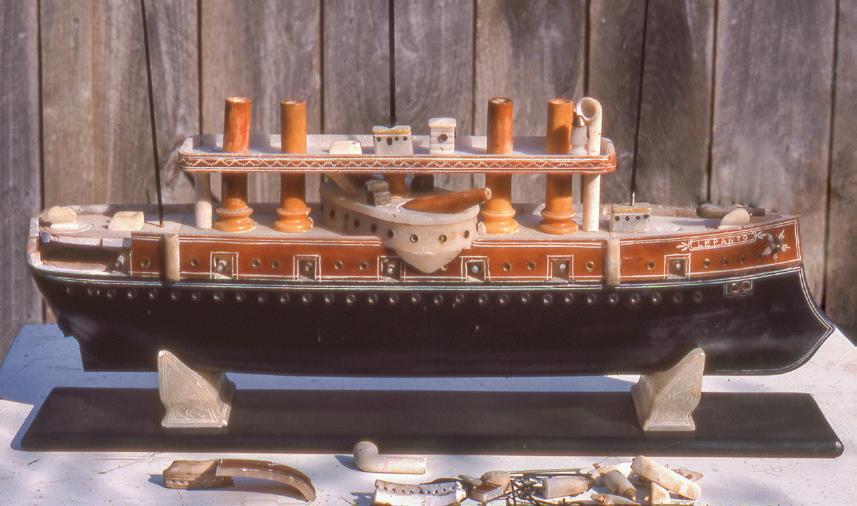

Private and non-museum institutional clients with model collections are generally less concerned with strict conservation rules. They still want jobs done right, but, less engaged in the materials debate, they want jobs done expeditiously. If asked, which they should be, they will likely permit use of regular PVAs, cyanoacrylates, and epoxies.
Materials and Processes
Model ships can be made of nearly anything. I’ve worked or consulted on models with hulls made of wood; clay; cast and worked metals; fiberglass and epoxy resins; plastics; fabrics (including medicinal adhesive tape!); silver; soapstone; real and ersatz bone and ivory; paper; tree bark; and glass. The name on the stern of a model of USS Constitution was spelled out with pasta alphabet soup letters. The hull of an Inuit-made model was a single walrus tusk that had been cut in half by C.I.A. agents anticipating a spy radio. While ship model builders get to choose their materials, modelers doing repairs and conservation do not. They will ultimately find themselves faced with stuff they know nothing about and that will give them headaches. Hopefully they will be interesting, at least.
Choices for materials used for repair, restoration, and conservation should be steered by the characteristics of the model on the bench. The proper path is to choose materials that reflect to the greatest degree possible the intentions of the original modelwright, whether the model is centuries old or relatively new. Often, it will be tempting to use modern materials that work quickly and easily, but decisions to use them should be made only in conference with the client.
Then the question arises: If work on an old model requires materials like those used by the original modelwright, must they be fashioned with the same tools and techniques as well? In a word: no. Unless the actual process is important to you or the client, the ends justify the means.
What do you do when a material or process is completely unfamiliar? Experiment to learn what may or may not work. Approach the problem from different directions. If it will not harm the model, try guessing. If there is no timely gain, then consult people who have the requisite experience. They may be other modelers, conservators, or materials specialists outside of ship modeling. Over the years, I’ve hired furniture and object conservators, a gun engraver, investment casters, circuit board printers, and other ship modelers.
When faced with replacing stranded glass running rigging on an early nineteenth-century French allglass model, glass conservators Sarah and Christopher Watts tried twisting together glass rods softened with a modern torch, but it was too hot. Trying increasingly cool heat sources, they discovered they could manage the job with a votive candle, a common item when the model was made. To duplicate processes from antiquity, we must consider frequently the tools and materials that restricted yesterday’s artisans so we can get the same results, like the Watts did. But we do not need to be constrained to using early techniques.
A tip to the prudent: When preparing material for a project, always make twice as much as you think you will need. This is the best way to assure that you will have enough at the same size. It’s always tricky to match previous dimensions, especially when working to small tolerances.
A potential source of parts for old models is old models themselves. Regretfully, it is sometimes necessary to discard a ship model. In the late 1970s, a collection of builders’ models of British steamships had been subjected to an explosion and flash fire, and I prepared an insurance claim for each model. Four were so damaged that estimates for their repair exceeded their insured value; they were totaled. The client opted for the cash and to dispose of the models. I wasn’t positioned, then, to assume custody of them. However, I thought their parts might be useful on other models
40
A roughly 20-inch-long folk-art model made almost entirely of soapstone, including the cradle and base, of the 1887 Italian battleship Lepanto
Cannibalized parts. Sample fittings stripped from two British builders’ models create a study in scales. From the top left are steam cargo winches; lifeline stanchions; turnbuckles (the larger, with a thimble, is fully operable), mooring bitts; cargo fall blocks; ladders; and steam whistles. Larger examples are from the 1:48-scale model of Mulbera; smaller examples are from the 45-inch, 1:96-scale model of the 1918 single-screw freighter Roseden, Case Study 24.
in the collection, someday. I requested and received permission to cannibalize each model for its parts and held them in trust for that collection. Occasionally, the trove provided parts (notably 1:48-scale operable turnbuckles for wire rigging) that were adopted for use within the collection until it was dispersed many years later. The parts in this trove and others I’ve scavenged have the fascinating side benefit of standing for entire modeling genres — their styles, workmanship, visual texture, materials, and finish. For one repair job, I recycled parts I had cannibalized from the Model Shipways kit of Fair American I had built in the early 1960s and discarded in the early 1980s. (Just for the record, I never saved any parts from the plastic kits I built as a boy.)
By the 1870s, printed card models started to appear. By the 1890s, British commercial model-building firms began offering ready-made parts for independent and amateur modelers. This didn’t happen in America until the early twentieth century. Concepts that drove development of modern kits formed in the 1910s and accelerated between the wars. Injection-molded plastic kits, an offshoot of Second World War technology, appeared in 1945.19 All these provided modelers with materials and possibilities they hadn’t been exposed to before. And, of course, more materials are available nowadays than ever.
For a truly remarkable review of materials that are used in the making and maintenance of all forms of the arts, there is the electronics database called Conservation and Art Materials Encyclopedia Online, or CAMEO. This Web site was built and is kept up to date by the Museum of Fine Arts. CAMEO “compiles, defines, and disseminates technical information on the distinct collection of terms, materials, and techniques used in the fields of art conservation and historic preservation.” Listings for more than ten thousand natural and manmade items include their basic characteristics, working and chemical properties, and much more.20
Repairs
It isn’t possible to report on all the ways there are to fix problems with ship models; we might as easily count barnacles on a ship’s bottom. I’ll mention some techniques here; there are more among the Case Studies. When doing repairs, keep in mind that it is important to preserve as much original material as possible.21
Somehow, a chunk of a model’s main rail has been crushed or completely lost. Rather than replacing the entire rail, it may be better to install a new filler called a “graving piece.”22 It is usually made of matching wood, so it looks, behaves, and takes finish like the wood it is replacing. Usually, a damaged area’s edges are rough. They should be squared and smoothed with knives, chisels, or files. Then a piece of wood is selected to match the species, color, grain, and, if possible, the figure of the original. If finishes are natural, then grain and figure are aligned with the existing rail. The new wood is cut to fit and glued in. Clamping will help make joints inconspicuous. The graving piece is then faired to the exposed surfaces of the original, then it is stained or in-painted to match.
Spars are always vulnerable. When struck or otherwise stressed, they break at weak spots (where there are internal sheaves or other holes), at points that provide fulcra (like mast caps and deck holes), and along their grain (if it isn’t exactly coaxial with the spar). Repairs to spars restrained by intact rigging can be managed in situ, but it is easier if they can be removed from the model. Spars should be repaired promptly, before other work on the model, including cleaning, causes feather edges along breaks to be softened, bent, or otherwise compromised. It is best to repair short breaks with internal, coaxial pins, but this is always awkward without removing the spar from the model. Long splits can be glued successfully. If ridges along the grain of both parts are pronounced enough, they can guarantee proper alignment. Either way, clamping is important. Transverse pinning can reinforce long splits. Binding a


41
All the fittings stripped from the 41-inch, 1:96-scale builder’s model of the 1948 single-screw steamship Admiral Fraser See page 166.
A complex arrangement of overlapping and abutting basswood graving pieces aid the reconstruction of the shattered bulwark of a 1:48-scale model of the 1916 American schooner-yacht Elena, Case Study 22.

Two pieces of a half-model's broken keel are being glued together using a rectangle of 3/16-inch glass as a surface plate. The squeeze clamps on each end hold the keel pieces flat on the glass. The keel break is compressed by wedges.
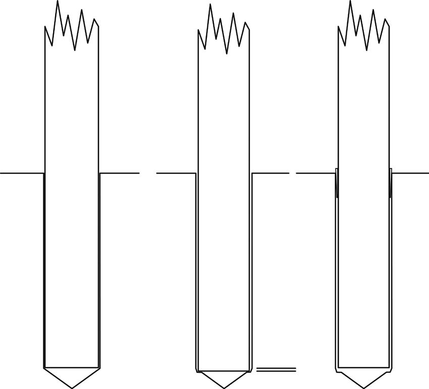
At A, a mast sits in a hole in a wooden hull bored with a regular pointed bit. In time, the mast dehydrates and shrinks in diameter and its heel compresses the wood in the step (B). The result is that the mast lowers a bit and rigging slackens. One solution is to manually lift the mast until the rigging is taut, then drive wedges (red arrows) around the circumference of the mast (C).
fractured spar with line or wire is a lubberly, unprofessional solution.
A couple of tricks are useful for aligning some pieces that are being glued together. If pieces must share a planar surface, clamp them to a piece of plate glass. The glass assures the plane, and being transparent, makes the back of the joint visible. Also, it’s handy use a V-groove in a block of wood to assure that two pieces of a broken spar align properly.
If a mast’s standing rigging is slack, it may be a symptom that the mast has settled in its socket in the hull or step. This is generally caused by dehydration. Proper repair will involve retensioning all the rigging, which is an enormous job on a complex square-rigger. There is temporary solution. If, when the mast is raised somewhat, the rigging becomes uniformly taut, it may be possible to keep the mast up by inserting small wooden wedges around the mast at the deck level.23 A more intrusive cure is to drill a hole as horizontal as possible into the mast where it enters the deck and insert a small pin or peg. This is only suitable if the surface that will bear the new load is hard and the spot is inconspicuous. The best fix is to remove the mast and insert a shim to hold it up.
We’ve all been tempted by the notion that a previously repaired glue joint that has failed can be repaired well enough if remains of the old glue on each surface of the joint are meshed perfectly — after all, it was this way before the old glue failed. But this does not work. Glue is meant to work when faying surfaces contact each other. Old glue prevents that. So, inconvenient as it may be, scrape, carve, file, or sand away that old glue so the faying surfaces mate completely, as they likely did originally. But there is a caution. When cleaning away old glue, avoid removing any of the wood to which it is stuck. Doing so, or sanding faying surfaces smooth, will alter the size of the original piece. In the cases of spars, it will make them shorter, causing original rigging to not fit properly. Be sure to spread glue evenly across the entire area of a joint.
Wood gets dented. Satisfactory repairs must be inconspicuous, especially in naturally finished wood. With an opaque finish, a dent can be filled with compound or a graving piece, then the area can be in-painted. For compound, I used regular household spackle or, for finer work, Lepage Polyfix, a product recommended by conservators that resembles drywall spackle, but has much finer fill and shrinks less. Dings in naturally finished wood are more challenging. One method is to use a syringe to inject hot water directly into the wood, parallel with the grain. Several injections may be necessary until the water erupts from the wood. The idea is that the hot water causes the wood to swell to its original dimension. The softer the wood and the fresher the ding, the better this will work; a fresh ding in pine will respond, but an ancient ding in cherry will not. A ½-cubic-centimeter syringe with a 0.013-inch-diameter needle used by diabetics works for me. I recently learned another method from Kirby Francis, a local luthier.24 If a ding has not broken the fibers of the wood, place a damp paper towel on the ding, then work over the towel gently with a hot electric soldering iron. This process steams the wood back into shape and works on older, harder surfaces.
Wire or rod lifelines are commonly found on steamship models. Frequently abused by rough handling, they tend to get distorted between stanchions. To a certain degree, they can be straightened with the fingers. But I have also found that rubbing a lifeline along its length between stanchions with the flats of a pair of sticks (like popsicle sticks or tongue depressors) works better.25
Half-hull models are generally mounted on backboards that frame them visually and protect them. But many half-models have been removed from original backboards to facilitate displaying more models in a given space or to provide them with uniform backgrounds. Older half-models of sailing vessels frequently have external details like stems, keels, sternposts, and rudders that are only attached to the models’ thin edge
42
A B C

along the rabbet. When a model so fitted is removed from its original backboard, these details are vulnerable. To reinforce the thin joints, intermediate hands often glued across the joints some sort of lining or backing such as cloth, thick paper, metal shim, or leather. Over time, these materials fail: glue holding metal shims parts, paper and cloth split and tear, and leather just falls apart. When these symptoms present themselves, I usually remove the linings and glue on replacements made of thin wooden sheet. Typically, I use 1/16- to 3/32inch basswood with the edges tapered so there are no sharp corners to catch anything. If a new backing piece is likely to be visible when the model is on the wall, I paint it black.
By the nature of their profession, conservators tend to use the least invasive techniques they can imagine for repairs. But sometimes these efforts don’t succeed. In such cases, repairs must be undone, cleaned up, and redone with stronger methods or materials.26
Finishes and Refinishing
In the realms of antique furniture and musical instruments, it’s understood that it is best to preserve an object’s original finish. It’s no different with ship models. In A Model Comes Through the Door in Part Two, I wrote that there’s no limit to the harm modelers do habitually in the name of restoration. The worst area for this is in the treatment of finishes. Way too often, someone says they stripped the old finish off a model, down to bare wood, so they could give it a “proper” new paint job. Make no mistake, wholesale stripping and refinishing is a bad idea. It insults the original modelwright and destroys the aesthetic and monetary values of a piece.
Like model-building materials, model finishes differ so widely it’s impossible to compile exhaustive lists. But we don’t have to. We must, however, have a sense for how to repair and preserve the finishes we encounter.
Conservators use a process called “consolidation” to stabilize and repair damaged or deteriorating finishes. They employ several methods that depend on the finish, the substrate, and the condition’s extent. The chemistry is mysterious to me, but the idea is to convince a finish that it prefers to stay put rather than peel, crackle, craze, chip, flake, or just fall off. Depending on the job, this is done by flowing a liquid adhesive called a “consolidant” under portions of an unstable finish. The consolidant’s vehicle evaporates, and the finish is reconnected to the substrate. Under instruction from several conservators, I have used B-72 (at 4-percent solution), parchment size, B500 Rohamere (which helps other chemicals combine), and isopropyl alcohol as consolidants. Surfaces can be prepped with other chemicals that will encourage consolidants to flow farther under the damaged finish and, thus, be more effective.
A dockyard model of a British 52-gun two-decker of 1774,27 which I worked on in 2008, had a boxwood figurehead that was finished naturally, likely with shel-
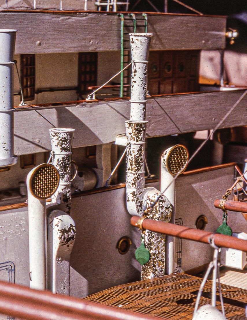
43
Failing Paint. White paint flakes from these brass ventilators probably because the surfaces were improperly primed. Also, the model suffered great temperature fluctuations that caused the brass to shrink and swell slightly, thus loosening paint. Notice the trompe l’oeil grating on the hatch cover. Details from the model of Orontes.
A new 1/16-inch-thick wooden shim backs tenuous joints between the keel, sternpost, and lifts of this early half-model without a backboard.
lac. The finish was split and peeling everywhere, but there was no loss of material. With a finely pointed brush, I applied isopropyl alcohol to the crevice where each tiny flake contacted the wood. This gradually softened the finish, and each flake could be curled down gently with the brush. The result was magic.
Another job was more complex. The seams between the lifts of a 9½-foot, 1:48-scale solid-hull builder’s model of a British India Steam Navigation Company liner of 188728 had opened because of dehydration, and the painted finish was crackled along many seams below the waterline. With the model rolled partially on its side, I worked along each seam in about 1-foot increments. I moistened a damaged area with water, then introduced isopropyl alcohol to the water to make it more penetrating. I flowed B500 Rohamere diluted 50 percent in water into the water-alcohol mix and left things to dry. Then I applied gum arabic as a barrier or primer to bare wood areas, in-painted the seam with watercolors, and matched the original gloss with acrylic gel medium. The ridges of disturbed finish were still visible, but less so, and they were stable.
On a 3½-foot, 1:48-scale builder’s model of a self-propelled hopper barge,29 white paint had flaked off a life ring; tiny flakes lay on deck. They were re-assembled, one fragment at a time, jigsaw-puzzle fashion, on the ring with parchment size.
Consolidation does not always conceal damaged finishes altogether, but that may be the maximum treatment that conservators and museums want. Other clients may want finishes repaired so models look reasonably pristine. This may require another set of procedures.
Surfaces will have to be cleaned and prepped. The border where a finish has suffered loss and where it is still healthy may need to be feathered to the substrate, usually with fine sandpaper, say 220-grit, then the substrate needs to be sealed with B-72 and in-painted. Or it may be better, if the old finish has a distinct edge, to
not feather its edge and to apply filler to the level of the old finish, and then in-paint. I fill with Lepage Polyfix and sand it to blend with adjacent surfaces with 220- to 600-grit paper.
For colored finishes, I now use almost exclusively artist’s acrylic paints from tubes. Colors can be matched with relative ease; can be mixed and cleaned up with water; and are reversible and noninvasive. I use a minimal color selection, which saves money and storage space. The colors I depend on are bleached and unbleached titanium white, neutral gray No. 5, mars black, red oxide, raw sienna, phthalo blue, and burnt umber. Brighter colors, like cadmium red and yellow, are occasionally useful as are iridescent copper, bronze, silver, and graphite. I use Liquitex and Golden products.
A 3- by 9-inch rectangle of 3/16-inch plate glass serves as my mixing palette. This is small enough to not crowd the work area, is convenient to hold, can be scraped clean quickly with a razor blade (when paint has dried), and is eco-friendly. Acrylic colors are generally lighter while being mixed and applied than when they are dry. A few years ago, I learned that when acrylics are viewed through the glass palette — from the underside — they will be the same value as when they are dry.30 When working away from home, I carry a 3- by 3-inch pad of sticky notes. The sheets make excellent disposable palettes because the paper is coated enough to not absorb paints.
Mixing an appropriate color takes educated experimentation. Once a color is close on the palette, I brush a tiny bit on the receiving surface to see what adjustments are necessary. I have a damp swab immediately at hand to wipe it away. Getting the color right, though, is only the first step. The second is matching the gloss. The wrong gloss will stand out worse than a wrong color; correct gloss can camouflage an imperfect color. For this, two products are indispensable: gloss and matte media. They are thick, uncolored liquids that can be mixed individually or in combination directly with paint or as an overlay to match the
44
gloss of a nearby finish. Companies marketing acrylic paints for artists also offer these products; it’s best to have both on hand.
High-quality sable brushes can lay down acrylics with almost no brush marks. If smoother is required, a flat brush damp (but not dripping) with water can smooth a still-wet paint surface before it sets.
For repairing natural finishes on wood, I have reasonable success with Zinsser white and amber shellac; Watco spray and brushed lacquer; and Minwax wipe-on polyurethane. They can be tinted with powdered pigments and wood stains.
Many late-nineteenth and early-twentieth century builders’ models have metal fittings that were polished or electroplated so they were shiny and bright. The finishes were protected with lacquer. This made for elegant but unrealistic models. (Who ever saw highly polished cargo winches or battleship cannon barrels on a ship?) Lacquer is difficult to brush because it dries fast, so it was applied quickly, frequently using a cloth pad. Coverage wasn’t always complete. Over time, less protected areas tarnished, thus leaving the effect of dark streaks swiped along still-protected bright areas. Where this has happened, the metal parts can be cleaned and polished and relacquered.
Perhaps a word is in order about finishes I no longer use. In the beginning, I occasionally applied linseed oil or furniture wax to brighten naturally finished wood. But they remain sticky enough to collect dust. Traditional spar varnish is wonderful on real boats, but it’s thick and buttery (as described by Dana Wegner31) on models, especially on small fittings. Floquil colors have finely ground pigments and are great for new work, but, because they are developed to match specific colors, primarily for model railroaders, they are hopeless for color matching in repair work.
Be wary of tapes. Before using any tape to mask a painting line (or for anything else) on old surfaces, make a test to ensure whatever tape you may have will not pull off remaining original finishes. Even so-called
“low-tack” painters’ tape can peel old varnish from a wooden surface.
Never assume that the coat of finish you are currently applying will be the last. Living with this expectation frequently leads to disappointment when another coat is needed to correct some tiny but unacceptable flaw. By always expecting that another coat will be needed, you will be delighted when you get to the point that none is. It is better to be pleased that you are finished than disappointed that you have more to do.
Gold was used on many vessels to highlight names, carvings, and other features. The same is true on models. Success in replicating the look of gold varies considerably. Real gold leaf usually doesn’t look great on models because it is garish. Paints offering gold (or other) metallic finishes seldom resemble the metal they are intended to imitate. Unless a model’s owner or provenance requires it, I avoid the re-application of real gold leaf. My trick is to understate a finish’s goldlike appearance, so it isn’t distracting. I apply a regular acrylic paint in a gold-like solid color, usually raw sienna. Then I sparingly apply a metallic acrylic paint (antique bronze gives a deep, rich tone) on the yellow. This provides highlights without attracting attention to itself.
Dribs and Drabs
None of us works quite as cleanly as we’d like. Glue oozes out of joints leaving glue goobies. Fibers tear off cotton swabs leaving the fuzzies we’ve already discussed. In corners too small to reach, reside the gunks of centuries, dubbed “kanorvna” by Racket Shreve.32 And, for ages, sailors have called those last few lines (and other leftover gear) that don’t get trimmed quite short enough “manavelins.”
The best policy is to remove these annoyances immediately, like typos when you’re writing. It’s counterproductive to think you’ll remember where each little

45
It is unlikely that the gun barrels, cowl vents, davits, and other fittings of the destroyer portrayed by this model were polished to a bright silver. Detail from a 74-inch builder’s model of an unidentified twin-screw, ram-bow destroyer.
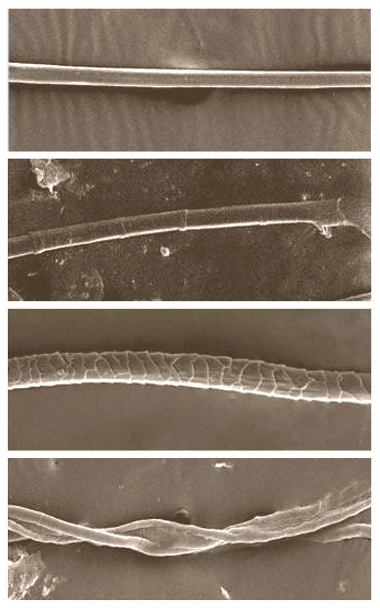

nuisance is and that you’ll get them all later in one pass. Even if you make a list, you’ll forget where you put it. While on the subject, most tapes leave some sort of sticky residue. If it’s on a hard surface, try rubbing it away with a smooth wooden stick. Art erasers work sometimes, as do the pink erasers on a standard Ticonderoga No. 2 pencil. I have also had luck with a razor-sharp chisel. And success can be had with Goo Gone, but it isn’t good for many surfaces.
Rigging and Knot Work
Ship models have been rigged with lines of all sorts. Originally, they were natural fibers — cotton and linen from plants, silk and wool from animals. Wire came on the scene in the nineteenth century, and synthetics appeared in the mid-twentieth. Including the above, I’ve treated models rigged with strands of baleen, boxwood, glass, nylon, dacron, polyester, hemp, and paper.
Since I became a citizen in the ship-modeling community in the 1960s, at least, it has stoked a love affair with linen as the line to use for rigging. It’s true that twisted Cuttyhunk-style linen fishing lines marketed by Ashaway, the Cape Cod Line Co., Newton’s, Gladding, and likely others that predated the advent to monofilament fishing line faithfully resemble three-strand rope in color and texture. It’s also true that linen, having been used for shrouding Egyptian mummies, has a reputation for longevity. Linen is hard, strong, and pleasant to work. But not all linen is wonderful, and too many modelers use linen that is soft, fuzzy, and twisted poorly just because it is linen. I have never understood this obsession, this linen mystique, because it works against good ship modeling. 33
Usually, rigging material can be identified visually, but closer looks may be required. Under a 300-power microscope, silk is as smooth as wire because it is extruded by the caterpillar; linen has subtly bamboo-like
jointed segments; wool is scaly (which is why it itches); and cotton has a sort of webbed double strand. Wire can be checked magnetically or by finding an exposed area and looking at color. Synthetics are smooth extrusions that are hard to identify.
To a limited degree, rigging fragility can be determined visually, before touching it. If many lines on a model have failed or have been damaged, little harm will be done to test a fragment for tensile strength. Dusting with a soft brush will reveal more. If fluids are used for cleaning around rigging, try to keep it dry.
Fiber rigging deteriorates from abrupt contact, gradual dehydration, acidic environments, exposure to ultraviolet light, and chafe. Running rigging usually fails before standing rigging because the former is lighter in weight, chafes on the sharp edges of unfaired rigging hardware, and is in harm’s way. If a line has failed between two points but everything else is fine, then it is victim of one or more of the first four problems. Natural fiber line survives far longer if its exposure to light is minimized. Linen’s integrity under normal conditions (that is, not in dark, bone-dry Egyptian tombs) lasts about two hundred years; silk’s about one hundred.34
Fiber rigging commonly fails at blocks for two reasons. First, acids in wooden blocks weaken lines. Second, lines chafe to failure where they pass through sharpedged holes in blocks that do not have faired sheaves. Ship modelers routinely coat fiber rigging with beeswax. Some conservators approve of this, but others feel that beeswax is too acidic and recommend avoiding it.
When rigging must be removed from a model, record it in a diagram. It can be schematic and not to scale. If losses are so severe that you can’t determine a line’s lead, check the model’s other side for clues — this is a significant advantage of the inherit bilateral symmetry of ships.
Scores of knots and other forms of applied rope work were likely in the repertoire of yesteryear’s salty sailor. A truly accurate model could mimic them all,
46
Photomicrographs of natural fibers at about 300x magnification. (Photographs by CNR-ISMAC, Institute for the Study of Macromolecules, Bielle, Italy)
Cross sections of two simple wooden blocks. In example A, the sheave hole was not faired, so the line is stressed unnecessarily at the sharp corners. At B, the hole was faired to resemble a sheave. The line through this block is not stressed, it is easier to adjust, and it looks far better. A
Silk
Linen Wool Cotton
B
and it’s safe to say that the larger a model’s scale, the more prototypical its knot work must be. Fortunately, modelwrights can succeed with relatively few knots. There are basic knots modelers should be as handy with as they are with tying their shoes. For illustrations of the following, I recommend The Ashley Book of Knots . The overhand knot is the simplest knot; it is easy to tie but can jam and be hard to loosen. The double overhand knot adds frequently desirable friction and bulk to the overhand knot. The square (or reef) knot is essentially a pair of opposing overhand knots that that can be released easily; even on models, avoid letting the evil granny knot try to pass for a proper square knot. The figure-eight knot is a handy small stopper. The half hitch is basic; it can be combined to become two half hitches or a clove hitch. The unsurpassed constrictor knot is the clove hitch on steroids. There are four or five ways to turn in a bowline; learn at least two so you aren’t always chasing the rabbit around the tree and down the hole. Proper bowlines can be untied easily. Knots formed from a rope’s individual strands, like the wall and crown, are only distinguishable at larger scales. Nothing looks better than a real eye splice; it will generate a large wow! factor, and it won’t pull out. There are other use-specific knots, but the above are the workhorses.
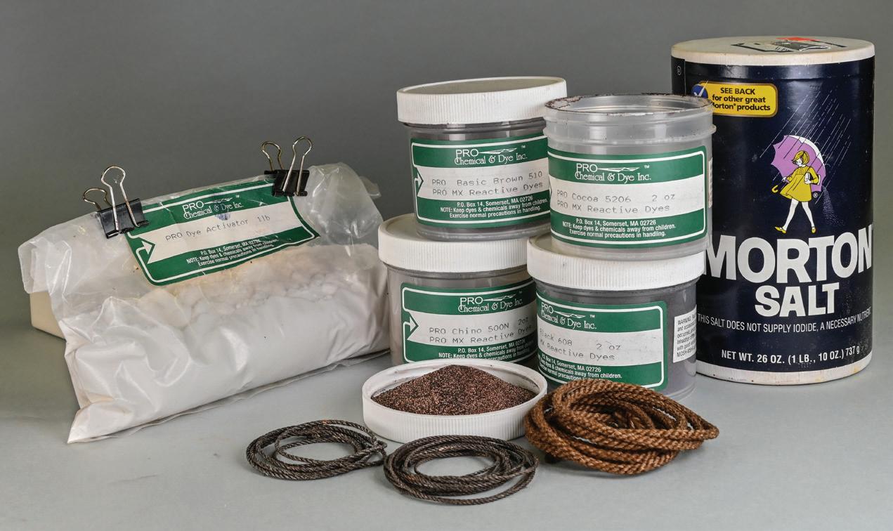
Depend on prototypical knot work, not glue, to secure rigging — after all, it worked on real vessels. Glue makes adjusting, untying, and retying difficult at blocks and belays. Some glues make lines brittle. On a model with taut, shipshape rigging, it may seem clever to spot-glue knots, but it isn’t. If knots are glued, there is no chance for fine-tuning by the original modelwright or a future hand.
Left. The three powdered components of fiber reactive dying are dye activator (in the baggie), the dyes (in plastic jars), and table salt. Each must be mixed in its own solution.
Below. Hardened rigging. Lengths of about 1/16-inch-diameter standing rigging became so rigid (like the spaghetti) with acidification that they don’t sag from their own weight. From a large, early folk-art model of a Dutch East Indiaman.

Belay lines on cleats, pins, and bitts properly; there are several correct ways. In all of them, the idea is to pass a line around a cleat or pin only a couple of times so it can be secure yet cast off quickly. Sailors do not store line by wrapping it around and around belaying points until it is expended. Learn to belay lines with tweezers in confined spaces. Learn the right ways to tie knots and to belay lines from sailors or from books about sailing, not from books about models.
Second- or third-generation rigging on a model usually exhibits less sophisticated knot work than that done originally. Why? The original modelwright had the advantage of being able to do delicate prep work off the model where there was more space and less congestion, and while all the lines were new and strong. Repairers are constrained because they must match materials and styles worked by an unfamiliar hand in frequently awkward places.
When replacing rigging, try to duplicate original fiber types, sizes, surface textures, and colors. To learn if two lines are the same diameter, hold them next to each other in front of a nonglare, light gray background; this prevents the illusion that lighter-colored things are larger than darker-colored things. Texture is the line’s lay, or twist. You might find the right stuff in your rigging trove (if it’s been growing for years), or you might
47

Double glue splice. The jib stay (A) passed through the ring of a tensioning inhaul (B), then forward and down through a sheave hole that was hidden by the blocks clustered at the jibboom's end. The stay had parted in the hole. A length of fine silk (C) was fed through the hole from below and glue-spliced to the stay there. When that had set, the silk was glue-spliced to the stay between the hole and the ring. Because there was no room to finger-roll the glue splice, it was clamped with retractable-hook test clips. To keep the clips from stressing adjacent rigging, they were laid on a card platform (D) that rested on both sprit yards. The green clothespin keeps the card from slipping aft. Tabs (E) cut and folded up from the card retain the clips. This is a modern, prisoner-of-war-style model frigate.

side of the break (B). The ends are inserted in the block (C), and the new lines are wrapped together inside the block so they look like (D). No glue is used.
have to make your own new line, which is a story on its own.35
To match color, line can be stained, dyed, or painted. Most standard wood stains will color fiber line, but they can be acidic and invasive. They can also be “fugitive,” meaning they fade with exposure to light. Color penetration is better on natural fibers than on synthetics. Some conservators stipulate coloring line with what are known as “fiber reactive” dyes because they are lightfast, they penetrate, and their colors can be mixed predictably. But the process is complex, time consuming, and messy. It involves creating three solutions; then prewashing the line, immersing and agitating it twice; and rinsing and hanging it to dry. I use products from Pro Chemical & Dye, Somerset, Massachusetts.36 Many folks casually suggest dying line for ship models with coffee or tea, but both are highly acidic and must be avoided. Water-thinned acrylic paints are handy for in-painting smaller amounts of line in local repairs.
Old line might have been glued where it was tied, belayed, or led through a block. If animal-based glue was used, knots can be eased by brushing on acetone and tweezing them gently until the line softens and releases.
Lines on some folk-art models become hard and brittle, like uncooked spaghetti. I’ve heard people say such lines are “acidified.” Pliability can be revived by soaking them in warm water with a few drops of nonionic detergent. The detergent breaks the surface tension of the water so it can penetrate the line. When the line dries, rigidity returns. Acetone doesn’t work here.
Let’s consider ways to repair broken lines without replacing them. These examples depend on the original line still having some integrity and a little slack. The first is the so-called “glue splice.” A line has parted in mid-length between two points; the ends are frayed. A dot of PVA glue is applied to one end,
then both frayed ends are rolled together between two fingers until the glue sets. The trick is to keep moving your fingers so the line doesn’t stick to them.37 If a line has parted at a block, you might insert one frayed end into each side of the block’s swallow and inject glue to hold them; but then the block is glue-clogged, which is bad. A refinement here is to put a short piece of similar new line through the swallow, fray both its ends, and glue-splice each new end to an end of the original line. But this increases the line’s length. A more elegant refinement is to clove-hitch a length of much smaller new line to each original end and lead the new lines through the swallow from opposite sides. Wrap the light lines around each other a couple of times in the swallow, then pull them through until the original frayed ends can be tucked into the swallow. Finish by in-painting the new line. The line will be the original length and there will be no glue in the swallow.
Knots securing lines directly to spars or fittings can mystically untie themselves, despite exhibiting no deterioration. Because an earlier hand likely snipped a line’s end off short, there is usually insufficient line to retie the knot. Further, the line’s fibers retain memory of the knot, making retying trickier. If the rigging system is slack and can run through blocks without failure, work the slack out toward the loose end — then there may be enough line to make retying possible.
Reeving frayed ends through small holes is difficult. Reduce fraying by working a little PVA glue, fish glue, or B-72 into the strands and twisting them together with the lay. Rereeving will be easier.
If there still isn’t enough slack in a system, check the line’s belaying point. Maybe there’s enough there and maybe it can be released so extra line can be worked back through the system to give the remote end enough length for refastening. This is where the original modelwright may have provided a useful resource for repair work, especially if he has coiled the line’s actual end instead of applying a separate, cosmetic coil.
48
D
A
C D C
E
B
B A
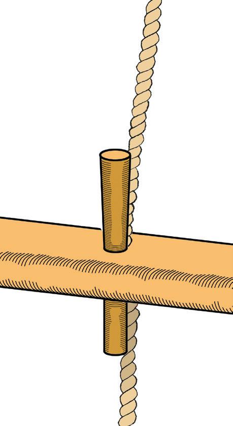

DThrough-mast splice. If two lines must end at the same hole in a spar, pass the bight of one line through the spar (A), pass the other line (B) through the bight, then pull the two ends against each other (C) until the bights are inside the spar (D).
Some modelers secured lines by passing them through holes in the pin rails where the belaying pins would go, then inserting the pins to jam the lines in place. With this quick, effective technique, the lines were reasonably adjustable, at least initially. Lines belayed this way are occasionally still pliable enough to be manipulated later, but usually they will fail where the pin enters the rail.
On simply rigged models, lines sometimes meet at holes through spars. A typical example involves the ends of topgallant shrouds where they act like futtock shrouds below the crosstrees. If these have failed, new shrouds can be passed down, through the crosstrees. Pass one shroud through the spar and back, to form a “bight,” or eye, then pass the other shroud through that bight. Work the ends against each other until the tension is right and the lines overlap inside the spar, then trim the ends.
A faux splice can be made easily even in surprisingly small lines by inserting the end of a line in the eye of a blunt needle. Work the needle’s tip through the

Faux splice. To make a convincing and strong splice in fine line, thread the line’s end through the eye of a blunted needle. Pass the needle under alternating strands of the line as shown, then pull the line through until an eye of the desired size is formed.

line three or four times, remove the needle, and pull the end through until the eye is the desired size.
If all the ratlines are gone, align replacements with a pattern. On a piece of card, draw horizontal lines the distance apart that the ratlines were originally. If none survive intact, remnants of the hitches that secured them to the shrouds may still be present, and these can determine spacing. Clip the pattern to the shrouds with retractable-hook test clips or small clothespins. If a model lacks precision, it may add visual texture to use the pattern for every fifth or sixth ratline, spacing others between by eye. Remember: ratlines rig parallel to the horizon, not to the sheer poles or rail. Model wire rigging is typically more durable and stable than fiber rigging. Still, it can suffer. It is usually steel, but other metals may be encountered. Copper wire rigging is found on some folk-art models; it’s usually slack because copper is more susceptible than other wires (including brass) to temperature changes, and it stretches easily. Unless a client makes a case for it, avoid copper.
49
A template for gauging ratline spacing behind the shrouds of the model of the Dutch East Indiaman of 1717.
A
B C
A line belayed by jamming it in the same hole with a belaying pin.
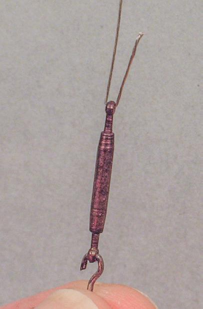
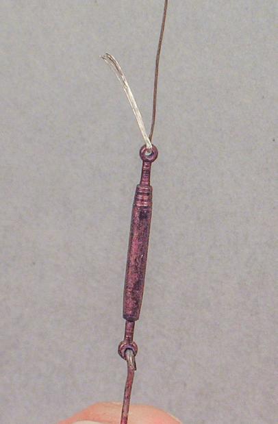

A B C D


In its earliest use on ships, in the mid-nineteenth century, a wire rope line was set up by turning its end around a fitting then back on itself, where it was seized, just like heavy fiber rigging. Later, end treatments became more elegant with splices and modern swage fittings. Wire clamps are seldom seen at sea.
Multistrand stainless steel wire rope is available in many sizes and configurations down to about 0.003inch diameter. I prefer softer wire that can be bent and shaped without spring-back and that will run easily through blocks. I have found success with wire rope products from Precision Scale Model Engineering.
When repairing or replacing wire on models, it must be set taut enough to remove spool memory and kinks; both look terrible. A good-looking faux wire splice can be made by bending a wire about, say, 3/8 to ⅝ inch from the end, inserting the bent end through a fitting’s eye, opening the strands back to the bend so they are flat and parallel (but not splayed), and fanning the strands into the lay of the wire’s standing part on the other side of the fitting. Loosely grip the strands against the wire with pliers. Simultaneously twirl the fitting and, with it, pull the wire and strands through the pliers. This action lays the strands into the wire’s lay. Serve the splice with fine thread and saturate it with B-72.
About Sails and Flags
Most of the old model sails I have encountered have been cotton, silk, or linen fabric, but there have also been paper, sheet metal, and carved wood examples. I’ve never encountered synthetic sails because I don’t work on modern pond models. Some sails are modeled as if furled, but most are depicted as fully set, either hanging slack from spars and stays, as in a calm, or formed to look full of wind.
The successful representation of billowing sails has been an elusive modeling goal for centuries. How do you convince a flexible two-dimensional object to remain three-dimensional? Some modelers shaped cotton sails by soaking them in varnish or starch and drying them on molds. Some sewed wire into a sail’s tablings, or outer hems, then formed the wire. Paper sails can be curled, but they won’t take compound curves without wrinkling. The same is true for sheet metal sails unless they are hammered.
The most elegant sails I have worked with are those that hang as if becalmed on the model of the French, ship-rigged, 18-gun corvette of 1775 at the Museum of Fine Arts. They are handstitched linen and so fine that they are nearly transparent; they are extremely fragile. The most evocative sails are those made by the H. E. Boucher Manufacturing Company on its models of sailing vessels underway. Perhaps the best-known of these is the iconic model of Flying Cloud, which is also at the Museum of Fine Arts.38 Boucher’s sails are multiple cotton plies laminated over wooden molds; we’ll investigate them in Case Study 22 of Elena.
Wooden and metallic sails can be treated like other model parts. But fabric has different needs, especially if it has been subjected to light for long periods. Think of window drapes that shred from their own weight after decades in direct sunlight.
Dust collects not only on the upper surfaces of furled sails, but it also clings to the textured vertical surfaces of set sails. Frequently, dust on fabric sails can
50
Wire rope splice. Pass soft, twisted wire rope through an eye (A); this is a 1:96-scale dummy turnbuckle. Open the wire rope’s strands so they are flat and parallel but not separated (B). Lay the open strands parallel to the twist of the wire rope and grasp gently with flat pliers (C). With the fingers, spin the eye to lay the open strands along the wire’s twist, letting the assembly spin in the pliers. The finished splice (D).
Finished splices. Splices on the fore and jib stays have been served with fine French linen. Detail of my 27-inch, 1:32-scale model of a 1912 New York 50 racing sloop.
be removed well enough by brushing them carefully with a soft ½-inch paint brush. Dust that has settled in an oily or smoky environment is more tenacious and problematic. The best cure I have seen is called “aspiration,” a technique I learned from textile conservators at the Museum of Fine Arts. It is basically vacuuming on a fine scale. Air is drawn gently through a 1/32-inch-diameter (or so) aperture in a polished-glass nozzle that is passed cautiously and repeatedly over a sail. The vacuumed air is water filtered to remove the dust from the atmosphere. The process is tedious and slow but reduces risk to the sail. A non-filtering device can be devised by adapting a small nozzle to a larger vacuum hose and controlling the vacuum with a rheostat to maintain a minimal draw.39 Aspiration should be done cold because heat can set the dirt. Be sure to keep moisture away from fabric sails while other parts of a model are being cleaned.
From the 1930s through the 1960s (at least), a “light weight unbleached…[and] fine quality” fabric called “Balloon Cloth”40 was marketed by Boucher and other retailers. This wonderful ecru cotton could be used confidently to replace sails on some fine old ship models. But it is gone now, and is not the same in texture, thread count, or quality as material being offered today under similar descriptions.
Paper has been used successfully for sails, especially on smaller-scale models. Some miniaturists prefer cig-
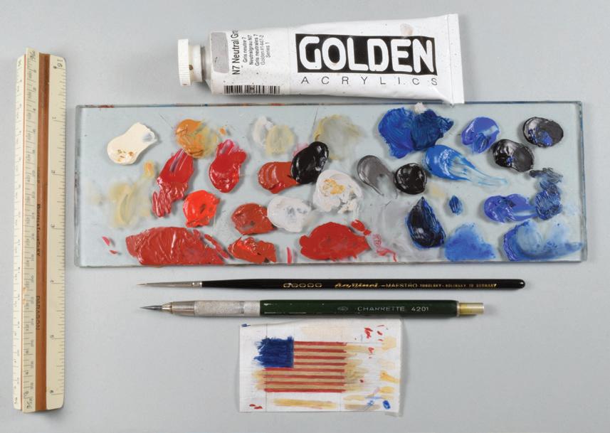
arette papers, but, by their nature, they are not made to last. If paper sails must be replaced, be sure to use acid-free or archival products. Art paper and conservation specialists offer suitable papers in wide varieties of weight, color, texture, and base material. Paper can be colored or tinted with thinned washes of acrylic paint; as noted for rigging, avoid tea and coffee.
Silkspan is a non-directional-weave plant fiber product useful for depicting furled sails but it is more often used for surfacing wings and fuselages on model airplanes. However, having been developed since the Second World War, it is inappropriate on older models.
As a rule of thumb, flags are more fragile than sails. Flags are made of lighter-weight material, usually cloth or paper, and sometimes metal foil. Hanging awkwardly by one corner of their hoist (the edge paralleling the pole), they are often shown extended stiffly to exhibit their iconography. This subjects them to different tensions than sails, the weights of which are distributed evenly along yards and stays: flags tend to pull or tear away from their halyards or poles. Crude repairs have been made by glueing the entire hoist to a pole, an untidy fix.
I have used three ways to make replacement flags. The first method uses paper. If the flag to be replaced was hand-painted, emulate its character and visual texture with a brush and paint. Tape smooth, acid-free rice paper to a piece of glass, then construct the flag’s
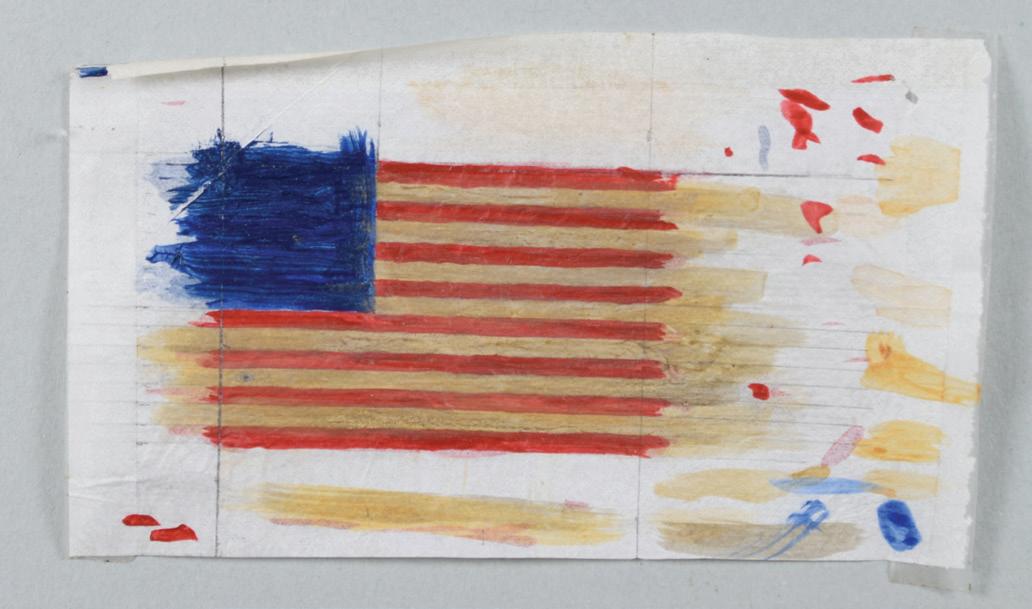

Far left. Tools and palette for painting a replacement 1- by 1½inch, 15-star American ensign made from rice paper for Donald McNarry's model of USS Constitution. See Case Study 5.
Center left. To make cutting straight lines easier, brushstrokes are not restricted to the flag’s outline. Note lots of tests for color and stroke.
Left. The new and shattered old ensigns compared. Yellowing of the original white stripes has been copied.
51
basic geometry with a ruler and needle-sharp 4H (or harder) pencil. Trace the drawing on the paper’s other side by backlighting it against a strong light. Make a palette of acrylic colors. Include acrylic retarder so the tiny amounts of paint and the brush will remain workable. To replicate a flag’s translucence, use thinned paint. The best technique for painting tiny stars was described by Erik A. R. Ronnberg, Jr.: “Let the brush tip form the star points using five radiating dabs for each star.”41
The second method also uses paper, but I construct the artwork on the computer in a program like Adobe Photoshop or Illustrator. I calibrate image placement so a flag can be registered to print accurately on both sides of a page. Inkjet printers do better than laser printers, and pigment-based inks will last longer than dye-based inks. Acid-free bond paper is good; lighter-weight stock can jam in a printer.
Older models likely had flags painted directly on fabric. They were usually cotton, linen, or silk. Use the same layout technique as for painted paper flags. Use paint thin enough to brush easily but thick enough to not run in the fabric. Be sure the first side is completely dry before painting the second side. Fabric flags are best on larger models.
I have seen eighteenth-century silk flags that have shredded to individual threads from exposure to light. The faint of heart would consider replacement. But the devout textile conservator will consider realigning every thread of warp and weft and mounting them on a substrate of crepeline, a “sheer, lightweight, open weave silk fabric.”42 In essence, they rebuild the fabric. I’ve never attempted this.
Transportation and Insurance
A significant amount of my business involves insurance claims for models that have been damaged during shipment. This is sad work because usually such damage can be avoided by making the right choices about
packers, packing, and shippers. For insurance claims, formal estimates must be submitted and respected, or things will get messy.
I’ve spoken with company sales representatives (not retail outlet clerks) at most readily available commercial shipping outfits such as FedEx, UPS, and USPS. Even with ads that indicate they will ship anything anywhere, they insist, nearly with one voice, that they will not knowingly ship a ship model. Yet, they do. And they say they will insure only those models they pack themselves. And their packing involves snuggly strangling models, even rigged models, in rigging-crushing bubblewrap or submerging them in oceans of foam peanuts. Both these schemes are lethal. The exceptions are half-models that can be wrapped in bubblewrap, packed in cartons so they don’t move, and shipped safely.
How are full-hull models transported confidently? I recommend three methods: private car, private currier, or fine arts mover. A nearby client will do best to put a model in the back of his car and drive it to my shop. No one will care for a model more than the person who owns it. If it is already in bad shape — which is why they’re bringing it to me — it probably won’t come to more harm in their car. When it’s time to return the model, the client and I take great care to assure the model, either cased or uncased, is secure in the vehicle. The model is cushioned on blankets, whether on a backseat or in an SUV’s cargo area. Cased models are generally top heavy, so they must be secured against falling over. A cased model can be secured in the backseat (with the bow to the right!) with a seatbelt and its buckle padded with, say, strips of cloth or foam to protect the case. Or cord or soft rope can be rigged to hold the case against the seatback by finding convenient belay ing points in the vehicle. Be careful: do not stress the flats of a case’s glass panes. If the model is riding in the back of an SUV, move the case forward until it braces against the back of the seat in front, then secure the case with cord. When
52
moving uncased models like this, the value of having full-size baseboards, as noted earlier, becomes obvious.
Only relatively local clients will want to deliver and retrieve their models. If the range is greater, or if deliveries must be made in difficult areas (I will not drive in New York City) then it’s useful to think about employing a private currier. Some curriers specialize in moving and caring for fine objects. For this service, preparing and packing a model is about the same as for a client’s car. The currier may prefer that the model, cased or not, be protected in a sturdy cardboard carton, sometimes called a “bin box,” that he can probably provide. He will manage the loading and securing of the model in his vehicle. Reputable curriers will provide a simple contract.
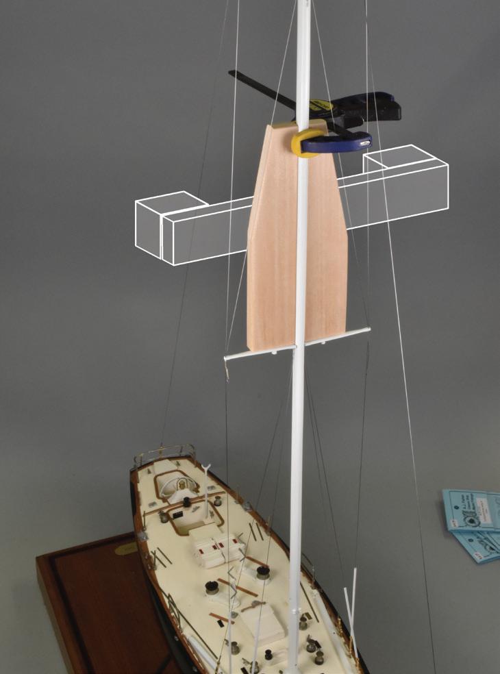
Models that are large, exceedingly valuable, or traveling long distances should be handled by specialists called “fine arts” movers. They are professional; they move paintings by Monet. After initial contact, a fine arts mover will send technicians to measure and assess a model. They will go back to their shops to build a sturdy crate for just that model. Back on site, they will install the model in the crate. It will rest on foam and will be braced with custom-cut foam blocking that will touch only safe surfaces on the model. Nothing will touch spars, rigging, or other fragile projections. The crate will be closed and taken away in an air-cushioned truck. This sort of service is justifiably expensive. There will be a contract for the crate, labor, transportation, and other fees. The by-product? You will have confidence in the move and own a nice crate.
If you must build a crate for others to handle, here are some suggestions. It will be heavy, but use ½- to ¾-inch
plywood to reduce chances of penetration and flexing in the larger side pieces. Decide if the model is going to be slid into the crate from the side or lowered from the top; it’s easier to slide cased models in sideways. Assure that the crate is a few inches longer, wider, and taller than the extremes of the model or its case. Use screws for assembly to avoid impact from hammers and to facilitate disassembly. Provide external handles for comfortable lifting without bending over. Line the entire crate with at least 1 inch of foam cut from sheets. If the model is cased, the entire space between the inside of the crate and the case should be filled with foam. Rest the model’s base or case on softer foam that can absorb vibration. Some movers use rigid foam, but this doesn’t keep old glue joints from failing. Relatively low, wide models, like modern steamships, will generally be stable enough on their own. But models with narrow keels and tall rigs, like modern sailing yachts, must be braced so they can neither pitch forward and aft nor roll side to side. Brace these models with foam blocking attached to the crate’s inner surfaces with hot glue. Brace really tall masts up high with athwartship blocking
Far left. By winding bubblewrap tightly around the hull and mast, commercial packers destroyed every piece of rigging and significantly damaged other details on this 22-inch, 1:32-scale model by Vincent Castello of the 1970 ocean-racing sloop Running Tide. The rest of the huge carton was crammed with bubblewrap.
Left. To return the model, a basswod block was grooved to embrace the mast and shaped to not touch any rigging. To the basswood was attached blocking (shaded shapes) that was screwed to the sides of a wooden crate. No stress was put on any replacement rigging.
53


to the crate sides. If anchors hanging from catheads or boats from davits can move, tuck foam or tissue around them to prevent chafe or breakage. Tie moveable cannon barrels together with thread to prevent losing them in the hold. Remember, the more professional a finished crate looks, the more professionally it will be treated by handlers; crates provided by some fine arts movers are elegant enough to serve as coffee tables later.
It is wise to discuss insurance with clients. I do not carry insurance for models in my care, and I make this clear. This is okay, because private clients usually have their models covered by homeowners’ policies, and in-

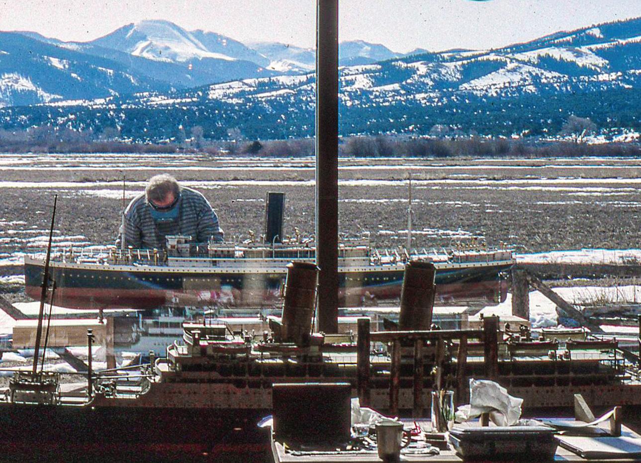
Far left. This model was packed well. The primary container is an extra-sturdy corrugated cardboard carton. Inside, the carton is lined with soft yellow foam panels about 2 inches thick. The model is mounted on its wooden base with heavy screws through short brass pedestals. Foam blocks, removed in this image, were packed tightly on each side, between the foam side panels and the hull at points where there were no details. Nothing else touched the model. This 1:96-scale model is of the single-screw 215-foot steam yacht Cythera of 1907 built by Ramage and Ferguson in Leith, Scotland.
Left. Cythera's baseboard (A) is protected by bubblewrap and rests on a full-size cardboard platform (B) that is stuffed with peanuts so it is firm but resilient. A cardboard sleeve (C) secures the baseboard to the cardboard platform. All of this rests on foam inside the shipping carton.
stitutional clients take care of themselves. Curriers and fine arts movers will be insured against loss or damage to objects in their care.
Taking the Act on the Road
If ship models can’t come to me, I go to them. In the late 1970s, I began accepting commissions to work on model collections away from my home studio. Initially, these jobs involved local, easy day trips. But then I got calls from farther afield. I’d pack a kit of tools, materials, and clothes and head out, in some cases, for as
Two spectacular but contrasting workspace views away from my home workshop. Far left, the view is in New York City, up Park Avenue toward Grand Central Terminal, the MetLife Building, and the incomparable Chrysler Building. The view to the left is of Trinchera Peak across a 2-mile-long meadow at 8,300 feet in southern Colorado's Sangre de Cristo Mountains. The model of two-funneled Orontes is silhouetted in the foreground, while my colleague Racket Shreve cleans the 108-inch, 1:48-scale builder's model of the 1907 Booth Steamship Company's twin-screw pasenger liner Lanfranc in the fresh mountain air. To the right, Tom Odell, who also accompanied me to Colorado, rerigs an accommodation ladder on the model of Magdalena.

54
B
C A
long as six weeks. I usually flew, but sometimes drove; later, I started taking the train. Sometimes I’d visit an individual model or collection only once, but other jobs required multiple visits for ongoing maintenance. I traveled regularly to Colorado for twenty-two years and to New York City for twenty (so far). I’ve also set up shop in California, Connecticut, Florida, Ontario, Rhode Island, and elsewhere.
When on site with large collections there is frequently insufficient time to do all the necessary work. That means either skipping some models entirely or doing only some work on all so each gets some attention. When it’s not possible to do everything, I identify in treatment reports the work that should be done as soon as practicable.
Ship model collections are not necessarily stagnant. Some collectors actively acquire and deaccession models. Once, several models that were sold from one collection I maintained appeared later in another. When this happens, it’s likely the collectors will expect different treatment disciplines. For instance, one owner may not care what glues or materials are used as long as a model looks good quickly, while a new owner may be extremely cautious about these things.
At the Second Western Ship Model Conference, aboard RMS Queen Mary at Long Beach, California, in 1996, I presented a seminar about various nuts-andbolts aspects of working far away from home. This talk became a Nautical Research Journal article.43 To save considerable space here, I refer readers to those pages for an expanded review of how to prepare and what to expect when working away from home.
I should mention that taking the act on the road became among the most appealing parts of my career. Travel keeps the job fresh and lively. It introduces me to new places, people, and customs. Some projects were complex enough that it was expedient to take a colleague from home on repeat visits. A particular camaraderie developed with three individuals. Racket Shreve and Tom Odell helped me in Colorado, and
John May joined me in New York. Moreover, time at remote sites is relatively pure; the telephone never (or hardly ever) rings for me, there is no mail, there are no interruptive chores or diversions, and I can work long, clear, productive, and satisfying hours on nothing but ship models. Life seems a little simpler for a few weeks, so: Have Tweezers, Will Travel.
About Photography
Like many photographers who began in the film era, I strove to ignore the inexorable advent of digital photography: I would never forsake film. But in 2003, a wonderful client in California requested frequent photo updates of progress on his model project. The timely way to provide them was with images sent by e-mail. So, I bought my first digital camera, a Canon G5 point-and-shoot. I was so smitten that I never finished shooting the Kodachrome in my film camera. Of course, once a camera and computer are paid for, digital photography frees picture taking from the burdensome expenses and time delays of film and its processing. It’s fun to have lots of sophisticated, up-to-date lenses, filters, flashes, and other stuff in your photo kit.

55
The shooting table in my workshop. The light fixture wires lead to a power strip below the table. The wooden slat across the table's leading edge holds the seamless backdrop paper down and provides a cutting edge when the paper is advanced.
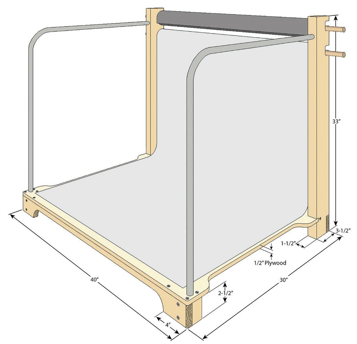
But I have learned that, for documenting workshop projects, it’s best to not let photography hobble the model work. For years I used low-end Nikon D5000-series digital single-lens reflex cameras with an 18- to 55-millimeter zoom lens. I have recently modernized to a Nikon Z-series mirrorless camera with an 18- to 140-millimeter zoom. My shop has a merciless mélange of incandescent, fluorescent, LED, and natural lighting, so I set the camera on auto white balance and let ’er rip. I use no filters because lighting can be manipulated and corrected so easily in today’s image processors. I use Adobe Photoshop and Lightroom. Photos exist to tell stories. Help clarify those stories by not losing your subjects in visually distracting bench and shop clutter. I once thought it was clever to use blue paper or cloth backdrops to evoke the sea and sky but now favor simple neutral gray or black backdrops to isolate subjects. Model detail gets blown out against too-contrasty white backdrops. And everything can be lost against pictorial backdrops, which never work, anyway. Include scale-defining tropes, like coins or pencil points, only if they amplify your story, otherwise they always destroy a sense of compelling impression or verisimilitude.
For photographing smaller items, I designed and built a shooting table. It supports two 36-inch rolls of seamless backdrop paper. (I can pull down 9-foot-wide seamless paper from a ceiling-mounted roll to shoot large items.) The table has two bent PVC rails for mounting four inexpensive, clip-on, diffuser-equipped photo lights and a power strip for their wiring. I use continuous lighting rather than strobes because the former facilitates modeling with the light. Experiment with lighting. Although you may get more light from several fixtures around a subject, multidirectional light tends to flatten subjects whereas monodirectional lighting creates shadows that can accentuate detail and help tell your story.
Depth of field has been the everlasting nemesis of ship-model photographers. We had to shoot at minimum apertures and extended shutter times to get everything more or less in focus from the bowsprit to the mizzen boom in quartering views. But in recent years a process called “focus stacking” has advanced enormously. The idea is to take many images of a subject, each one focused slightly farther along the subject, from front to back, than the previous one. Then focus-stacking software renders the group of images, taking the sharpest areas of each and marrying them into a fully crisp image. Focus stacking can be managed in Photoshop or in stand-alone packages. I prefer Helicon Focus. Some cameras can now manage focus stacking internally. ¯

56
A B
Focus stacking. Image A is a single exposure straight from the camera. On the upper scale, only the numeral 5 is in crisp focus. Image B has been focus stacked in Helicon Focus from twelve separate exposures focused incrementally along the length of the 6-inch scale. All the numerals are in focus. The shutter speed was 1/500 and the aperture was f/5.3 for all exposures in both images.
A schematic of the shooting table with basic dimensions.
Part Four Case Studies
Introduction
This part reviews some repair and conservation projects that have passed through my shop.
From the roughly twenty-two hundred models on which I have done repair and conservation work, I have chosen as Case Studies twenty-nine jobs that offer one or more specific experiences that I hope will be interesting and useful.
Most repair commissions are relatively straightforward, while some are complex and lengthy. Reflecting this, the following Case Studies run the gamut from brief notices about a single feature on a repair job to substantial rebuilding efforts. There is no way that the Studies can contain every task I performed on the models. Two stories, those of Valkenisse (Case Study 2) and Princess Royal (Case Study 3), have been published as full-length books. I include them here because they contributed significantly to my career, but you will do far better to find the books.
These Studies are arranged according to the chronology of when the original vessels sailed the seas. First, this advances the notion that there is no predicting what sort of model work would cross my threshold on any given day. Second, this is how most albums and catalogs of ship models are arranged. The progression helps relate the evolution of ships, a story that is perhaps more important than the evolution of models.
Some information is provided for vessels represented by the models, but it is inconsistent because the
models and vessels have such varied uses and histories. I include such things as designers, builders, critical dates, and basic dimensions when I know them. Some topics — for instance the history of a trade or a vessel — are broad enough that general readers should be familiar with them or can find them in the maritime literature. Racing records for yachts and combat records for warships are omitted because they can be traced easily and mean nothing to readers uninvolved with those specific vessels. Further, compiling and presenting such material devours resources.
A note about scales. The fractional method of expressing scales (as example: ¼" = 1') shows exactly what distance on a model, ¼ inch, equals 1 foot on a ship. This notation is convenient enough, but fractions do not work for all scales. I express scales as ratios (in this case 1:48) because doing so is consistent across all scales.
Working on a model obviously teaches me about the model’s characteristics. And these, in turn, teach me about its modelwright. After working on any model, I feel I have met its builder to some degree. Although not directly related to model treatment processes, I have taken, for some better-known modelwrights, the opportunity to tell their stories, especially if I have been privy to inside information. Some I’ve known personally or through correspondence; others I know through their works and reputations. In one case, I lived in a model collector’s house for three successive winters. Sharing these stories makes the case studies more relevant to me and might help other modelers better understand their own projects. ¯
Case Study 1
Unidentified
1695: English 48-Gun, Fourth-Rate Ship of the Line
Contemporary Rigged, Full-Hull, Dockyard Model
A
bout three and a quarter centuries ago, somebody was busy building this model. The time was seventy-five years after the Pilgrims landed at Plymouth, about thirty years after the Netherlands ceded Manhattan to Britain in favor of trade to Indonesia, and about one hundred twenty years before the American colonies seceded from Britain. This was an old ship model. Its stern displayed a bust of England’s King William III, but not of his wife Queen Mary II, so the model was tentatively dated to shortly after her death, or 1695.1

The model portrayed an unidentified English fourth-rate ship of the line. It was pierced for forty-eight guns on two full-length gun-bearing decks and the quarterdeck, but there were no weapons aboard. It was a 1:48-scale, full-hull model built in the plank-onframe style of English dockyard or Navy Board models.
As a class, these models are certainly the most elaborate creations in the ship-modeling world. Volumes have been written about their utility, aesthetics, history, evolution, and provenances, so it’s unnecessary to review them here. Readers desiring more information should refer to works by John Franklin, Arnold and Henry Kriegstein, Brian Lavery, Simon Stephens, and Grant Walker. Details are in the bibliography.
This model’s provenance is not known prior to its ownership in the early twentieth century by Clarkson A. Collins, Jr., a New York ship model collector. The model remained in the Collins family until it was acquired by its current owners in the 1970s. Contrary to at least one published record, it was never in the collection of Henry Huddleston Rogers. “With the exception of the masts, spars, and lower shrouds,” the rigging dates from Collins’s ownership. A considerable amount of cleaning, repair, and conservation work was done on the model by Philip Wride, an English ship model specialist, during the 1980s.2
When it came to me in 2015, the model presented two primary challenges. The first was that, when
viewed from broad off the beam, the mizzenmast raked forward inappropriately and unattractively. It was unclear if the mast was just stayed too far forward or if it had warped. If the latter, all the warp seemed to be, at least in photographs, in the few inches beneath the top. The second challenge was that there were no lower catharpins rigged in the fore or main shrouds.
The initial idea for correcting the mizzen problem was to slack off all the rigging that pulled the mast system forward and haul in on all the rigging that could pull it aft until the system was vertical and the warp, if present, was straightened. This seemed possible. But the strain would be severe on old and probably tired light-weight lines. It was like this: The mast was about the diameter of a standard wooden pencil. It would take considerable force to bend a pencil a few degrees in a short part of its length. If the lines weren’t up to the task, and if the mast had indeed warped, the second-best solution would be to replace the lower mast. But that remained a last resort.
Several rigging systems pulled the mast forward: the mizzen lower and topmast stays, which connected to the mainmast or its shrouds; the crossjack and lateen mizzen braces, and the mizzen topsail bowlines, all of which also connected to the main shrouds; and the main topsail and topgallant braces, which led to the mizzenmast. All these lines, except the lanyard for the mizzen stay, belayed at the rails or on deck.
The farther aloft and the more complex the tackles associated with these lines were, the more line would have to be paid out of each to let the upper portions of the mizzen shift aft far enough to be vertical. The highest affected lines, the hauling ends of the mizzen topmast stay bridles, would each require a few inches. Belays for some lines did incorporate small contiguous coils that could be exploited for their length, but none for the higher rigging were long enough. These lines would have to be replaced.
No mizzen standing rigging led far enough aft to be of significant help. This meant the task would rely
58
Vertical blue tape on the foamcore behind the model illustrates the mizzenmast’s forward rake. The mainmast is verticle, but appears to rake because of perspective.
on running rigging on the lateen mizzen yard. This included the hauling end of the mizzen topping lift, the double brails abaft the mast, the sheet, and the mizzen topsail braces. These lines had no length problem because they would be shortened. But the strain on them would be considerable, and possibly too much.
Regardless of the correction procedure chosen, the first steps were the same. I made a photographic record of the mizzenmast, its rigging, and the area around it. I wrote down each line’s lead as it was cast off from its belaying point. The mizzen lower shroud lanyards were released, the mast tackles were unhooked from the channels, and the futtock shrouds were unhooked from the lower ends of the topmast shroud futtock plates. All of these would require adjustment later.
Casting off each line at its belay was not entirely successful. Some lines had aged to the point of having little or no flexibility, and they failed. For instance, all eight mizzen shroud lanyards crumbled when their hitches on the shrouds were untied. I cut them away and used a drill to ream the fibers out of the deadeyes. I believe this work was from Collins’s hand.
With rigging no longer constraining things, a straightedge held against the lower mast revealed that there was little or no warp (perhaps it had been a photographic illusion). And, with my finger, I could — with some, but not much effort — push the mast aft until it paralleled the mainmast. That was a great relief!
A four-step plan was developed for resetting the mizzen. Each step involved the long lateen mizzen yard. First, the articulation of the yard at the point where it crossed the mast had to be as secure as possible. I overhauled (tightened) the parrel and its fall and the halyard’s fall. But this wasn’t enough. After conferring with the client, it was decided to pin the yard to the mast. I did this as inconspicuously as possible with a short length of 1/32-inch-diameter brass rod placed horizontally and athwartship through the yard. This provided a fixed fulcrum for the yard’s rotation.
Second, the sheet, which attached to the lateen yard just forward of the mast and belayed on deck near the stern, had a good angle for controlling the rake. Third, the brails and topsail braces would hold the yard’s aft end down. Fourth, the mizzen topping lift would pull the topmast head aft toward the lateen yard. I tested the existing rigging to see if it was strong enough. Not all of it was. The sheet, likely a Collins-era line, parted at its block. The other lines were rigged later, probably by Wride, and I thought they might hold. Nonetheless, to reduce chances of failure, I replaced the aft brails and the hauling end of the topping lift. I left untouched its lovely, complex bridle system on the assumption that it distributed strain as it was designed to do.
New lines are ecru Pearsall’s Chinese Twist silk. When the lines were adjusted to rake the mizzenmast properly, I stopped them temporarily with retractable-hook test clips. I rove off new shroud lanyards, then reset all the lines between the main and mizzenmasts. The challenge was to make them look taut without putting additional tension on the lines pulling the mizzenmast aft. New line was installed where old lines were no longer long enough.
Although the mizzen topmast’s trestletree-crosstree structure had been built properly, it had, at some point, been reinstalled upside down by a previous hand. This wouldn’t have been a problem, except such timbers properly taper on their bottoms, and now these tapers were on top. It would be simple to flip the structure, but the stack of rigging at the topmast head held it down. The stack included the topmast shrouds’ eyes, the standing ends of the topsail lifts, and the strops for the lateen yard topping lift and topsail lift blocks. There was also the topmast stay’s collar, and, seized to it, the topsail halyard collar.
The eyes gripped the masthead solidly. I was concerned that the stack might have solidified, as old model rigging sometimes does, and I didn’t want to break anything. I used the wiggle technique, gently working the stack one way then another until everything released.
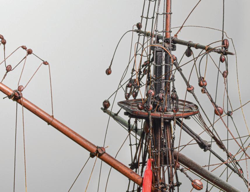

59
The tangle of lines around the mizzen top after releasing enough rigging to adjust the rake.
The mizzen topmast trestletrees-crosstrees unit is upside down.

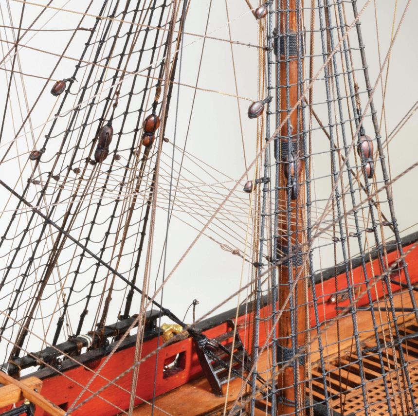
The topmast shrouds’ futtock plates were lifted out of their mortises in the top to provide enough slack.
The stay collar was large enough to lift over the trestletrees-crosstrees unit, but the halyard collar was not. Luckily, the structure could rotate within the halyard collar. Finally, I slid everything up and off the masthead. Working quickly because I didn’t want the eyes of the sundry lines to lose their memory and get confused, I flipped the trestletrees-crosstrees unit and reinstalled it on the masthead. Then the rigging was replaced in its proper order, and its stack was settled until the unit seated properly on its mast stops. When the futtock shrouds were reassembled, the task was complete.
Lower Catharpins
Simple in concept, catharpins were lines used to pull together the shrouds on each side of a lower mast to make the entire shroud system tighter — this in an age when lines stretched constantly because rigging materials were not as stable as they were to become. There were upper and lower catharpins. The former rigged between the port and starboard futtock staves and served to counter the outward pull on the lower shrouds by the topmast shrouds via the futtock shrouds. Upper catharpins nearly always appear on models. But we are concerned here with lower catharpins. British historian and ship modeler R. C. Anderson wrote that these appeared less frequently, perhaps because “they were a sort of emergency fitting used to set up the shrouds quickly in case of need, but not left permanently rove.” He recommended fitting them on models “because they look well and are very easy to do.”3 I agree: They look good. But to make installation easy, there is no doubt whatsoever that they should be rigged as early as possible. Doing the job with all the running rigging in place should be avoided, especially if it is frail.
In his analysis of English sailing warship rigging, James Lees reported that, during the period repre-
sented by this model, catharpins were rigged “about one third up the [lower] shrouds.” But he didn’t say from, or between what, that third should be gauged. Anderson came to the rescue: they were rigged “about halfway between the rail and the futtock staff.”4 Unfortunately, at this height on this model, they would be fouled by the upper blocks for the mast tackles. I rigged them just a bit lower.
Blocks and line for the fore and main lower catharpins had been prepared by Wride, but not installed before his retirement. He had made and stropped the blocks and had arranged them and the line on a card. I transferred each block to a shroud, where it was secured with a square knot.
Diagrams for catharpins show that one set of crosses passes under the other set. If you rig catharpins, you’ll find it far more sensible to install the lower batch first if you want to keep your sanity. The trick was making catharpins look taught without bowsing in the shrouds. Before starting, I turned a faux eye splice into one end of the line. When reeving off the long line, I led it initially through the blocks just far enough to see sense in the system. Later, I overhauled the line so it was taut and crisp at the blocks and the eye splice was right at the first block. The position for the eye in the other end was calibrated to leave a ¼- to 3/8-inch gap between the ends. This second eye had to be made in situ, a sketchy operation inside the rigging. The eyes were secured together with a lanyard to finish off the catharpin.
Knots and Rods
About thirty-five lines on the model had to be repaired or replaced. Several styles of knot work had secured the standing ends of lines. To respect the original modelwright, in each case where a line had to be replaced, I copied its original knot work. New knots, but not belays, were touched with fish glue diluted 50 percent in water.
Not wanting to miss an opportunity, I inspected the model’s interior with a borescope. It was an inexpensive
60
Brass rods (arrows) clipped across the shrouds on both sides serve as guides for seizing the catharpin blocks in level rows, and the flat brass bar across the rigging assures that the catharpins will be level. Working inside this maze was difficult.
The web of lower catharpins installed in the main rigging.
General Tools model intended for use by house carpenters and electricians to see inside walls. The 5/16-inch-diameter probe, equipped with a four-bulb LED and a camera, was at the end of a 36-inch moderately flexible snake attached to a handle that had no facility for on-board viewing of what the camera saw. Instead, the unit sent a signal to an app on a smartphone. The view could be watched on the phone and recorded as still or video imagery. This wasn’t sophisticated gear, but it worked in a Stone-Age kind of way. Unfortunately, the probe didn’t fit between the hull’s frames, but it passed nicely through the gunports. It was guided by twisting and turning the handpiece, while my eyes watched the iPhone propped up nearby. The LED was not strong; its light barely penetrated the gloom. Expected items drifted into view: the masts, the capstan’s undetailed lower barrel, the inboard ends of the anchor hawsers, and so on.
An interesting discovery was the presence of three transverse rods that had nothing to do with seventeenth-century ship construction. Inboard, their port ends, which I saw through starboard-side gunports, protruded from the clamp for the upper deck. (The model had its starboard ports open and port ports closed; the latter resisted opening, so I didn’t fuss with

them.) The rods were 1/16 to 3/32 inch in diameter, silver-gray in color, and, when clicked with tweezers, sounded and felt metallic, but they were non-magnetic. I searched outboard for evidence of them. Sure enough, their locations were visible on the lower strake of the upper wale, to which the fore and main rigging backing links were nailed. Blemishes on the wales’ outer surfaces at the location of each rod looked like holes that had been filled with compound and in-painted. One was above the No. 3 lower deck gunport, the second was at the accommodation ladder steps, and the third was about ½ inch forward of the No. 8 gunport, under the bulkhead at the quarterdeck’s break. What were the rods for? They were certainly not original gear. The only explanation I could envision was that the model was at some point deemed to be dimensionally unstable, and someone had hoped the rods would stabilize the sides in a manner that the model’s structure had been failing to do. My clients did not know about the rods, so the work predated Wride. This left Collins or an earlier hand. The visible parts of the rods were smooth. To hold the sides together, wouldn’t they have to be threaded? Perhaps they were glued in their holes. Regardless, they became a mystery that we couldn’t solve. ¯


61
The arrow indicates where a rod penetrates a black wale. Work on the model has been completed.
An athwartship rod (arrow) viewed through a gunport.
Case Study 2
Valkenisse
1717: Dutch East Indiaman
Contemporary Rigged, Full-Hull Model
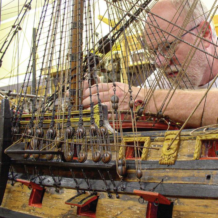
In 1932, the Museum of Fine Arts accessioned a large, atmospheric model named Valkenisse and dated 1717. It was unrigged, but was accompanied by a bundle of spars, deadeyes, blocks, rigging, and other gear. In 1993, I accepted a commission to reunite the parts and the model. The extant parts either predated the model’s known modern history or had been made in the 1920s for the model by its previous owner, Clarkson A. Collins, Jr., of New York. I had naïvely thought all the older parts were original, that those made by Collins were usable, and that it would be relatively simple to reassemble everything. However, after two research trips to the Netherlands and lengthy communications with Albert Hoving, the ship-model curator at Rijksmuseum, Amsterdam, we concluded that Valkenisse was a historically significantly model. It stands as a document that reliably presents how early eighteenth-century Dutch merchant vessels and models of them were built. But it had fallen on strange times.
The contemporary model portrays a known Dutch East Indiaman of the largest class. There are only about a dozen such models in Europe, and Valkenisse is the only one to have found its way to the Western Hemisphere. We determined, in the end, that only three spars and some rigging hardware from the bundle were original and, unfortunately, that Collins’s new work was not going to be appropriate. Amazingly, someone had tried long ago to alter this wonderfully Dutch model so it depicted a British ship. In doing so, he violated nearly all the concepts of respecting original modelwrights. Valkenisse’s story is one of discovering and interpreting evidence that was hidden in plain view. To do this satisfactorily, I had to compensate for an innate, but misaligned Anglocentric astigmatism that preached that the only right way to build a ship was the English way. I had to familiarize myself with a strikingly different but equally successful shipbuilding tradition. Among the challenges were learning an arcane mea-
suring system and determining the 69-inch model’s unusual scale of 1:29.3.
In addition to the bundle’s contents, many other items required adjustment or replacement so the model would be as representative of its era and heritage as possible. This was the first major project I did with the guidance of trained conservators, so it was the first in which I applied their philosophies and techniques. When, after a few years of on-again, off-again work, the task was complete and the model was installed, I prepared a lengthy treatment report. It discusses Valkenisse’s known history, the model’s provenance, and all the significant steps that were taken to research and rebuild the model. The treatment report was adapted to book form and was published as Reconditioning an Eighteenth-Century Ship Model, ValkeniSSe, Retourschip of 1717. Rather than take more space here to relate the processes, I recommend the book. ¯

62
Adjusting rigging at the base of the foremast on Valkenisse. (Photograph by Peter Hickey)
The model of Princess Royal was built concurrently with the vessel it represents, which was launched in 1773. The model is now part of the Rogers Collection at the U.S. Naval Academy Museum. The 54-inch, 1:48-scale hull is constructed in what is called the “Georgian” style. This means a solid softwood so-called “core” was carved to the hull’s dimensions inside of planking, then the core was planked all over. Inboard, the core was carved to the shape of the frame’s interior down to the lower deck; the hold was unfinished. From the lower deck upward, the core was ceiled with planking, and the structural work for all the decks was installed. The lower deck was planked, but those above it were unplanked. The result was a model that looked like it had been built in the plank-on-frame style. The interior was fitted with compartmentalization and fittings, and the exterior was decorated elaborately.
Beginning in the 1990s, the interiors of Princess Royal and other models in the Rogers Collection were given regular endoscopic exams by Grant Walker, the museum’s education specialist. It was observed that small structural pieces called deck “ledges” were falling with
accelerating frequency inside Princess Royal. The cause was the evident athwartship expansion of the model’s core. Each ledge fit a unique spot, but collectively they were largely indistinguishable; there were about a thousand of them. If all the ledges fell in, it would be impossible to reconstruct the hull confidently. Before this happened, the decision was made to pre-emptively dismantle the model’s interior, to correct the core’s shape, and to reassemble the model. I was given the contract to do the job, which began in 2006.
Case Study 3
Princess Royal
1773: British 90-Gun, Second-Rate Ship of the Line Contemporary Unrigged, Full-Hull, Dockyard Model
Among the project’s largest challenges was to develop a system for cataloging parts as they were removed from the model. An alphanumeric system would have been incredibly cumbersome. Instead, I developed what were later dubbed memory boards (see Memory Boards in Part Three). This analog method involved wiring each piece to its own image in a large photograph of the deck structure on a piece of foamcore.
Adjusting the core’s shape was another challenge. The solution was to build bulkheads on each side of the model like the sides of a dry dock. The bulkheads were penetrated by long adjustable bolts that seated in socketed blocks fitted to each gunport. By turning the bolts, the hull’s shape could be controlled with ease. This device became known as the corset because it managed the shape of the Princess’s midsection.

This colossal project involved hundreds of subtasks and, in all, consumed about eighteen months in Annapolis and Newburyport. It was fully reviewed in the treatment report submitted to the museum. As with Valkenisse, the treatment report was also adapted to book form and published as Legacy of a Ship Model, Examining HMS prinCeSS royal, 1773. The book provides a far more complete story about Princess Royal than I can tell here. ¯

63
Wiring pieces of the model of Princess Royal to the memory board for the upper deck with Howard Chatterton (left) at the U.S. Naval Academy Museum in 2006.
Case Study 4
Warrior
1781: British 74-Gun, Third-Rate Ship of the Line Contemporary Full-Hull, Prisoner-of-War Model


Warrior was an Alfred-class 74-gun thirdrate ship of the line launched from England’s Portsmouth Dockyard in 1781. The vessel participated in the tactically significant Battle of the Saints in 1782 and the Battle of Copenhagen in 1801. She later served as a receiving ship and a temporary quarantine ship. She was broken up in 1857.5
This model is in the typical style of a full-hull, rigged, wooden prisoner-of-war model that dated from the Napoleonic Wars. Fairly colorful for an example of this genre, Warrior’s 9-inch hull had a green bottom. Many details, like the decorative work in the stern galleries, were done in watercolor on paper. The window mullions were thread.
When it came to me in 2013, the model was in good condition. It required a light dusting with a soft, dry brush. The rigging, which is frequently fragile in models this old, had no parted lines. The client reported to me that the model had been “restored,” and if this included all the rigging, it was done by a skilled hand who lent a compelling impression of age to the model.
The display case had problems. The wooden base was a pine board surrounded with a plain but poorly mitered molding. The glass vitrine’s corner seams were concealed by glued-on wooden veneers. The case was recent, but it verified that displays, as well as models, can be the victims of dehydration. The base had warped quite badly. In the center, it now arched upward about ⅛ inch in just 53/8 inches of width. The warp was severe enough that the vitrine’s lower edges seated uncomfortably. It rocked from side to side, and one glass pane had cracked.
There were four screw or nail holes in the base’s bottom, but they were not aligned in any way that involved Warrior. In other words, this board had once been used for something else.
It is important, I believe, to offer a model the courtesy of using good materials and workmanship in its display. Because the display is part of the piece, the display should be as dignified as the piece. Here, the used,
warped, and poorly finished baseboard negatively impacted the model’s respectability. The case had little or no historical significance or connection to the model, so the client and I decided to reinstall the model in a wholly new case of the same dimensions. It was made by case specialist Dan Martin of Collector’s Showcase in Granby, Massachusetts.
The model balanced on two narrow cradles that offered it scant transverse stability. It could have fallen out easily. A pair of fine black fiber guy lines between the model and small metal eyes in the top of the base provided minimal additional restraint.
The bottom of each cradle had one tenon that fit snugly in a mortise in the old base. I wiggled them loose. Each mortise had been made by drilling two adjacent holes into the base and cutting out the wood between them with a chisel. I transferred the mortise locations to the new base, marked them with blue painter’s tape, and cut them. I discarded the original eyes and twisted up new ones from 24-gauge brass wire. The old cradles and new eyes were glued into the new base.
For new guy lines, I used Sherwood brand 5-0 black surgical braided silk suture. At about 0.005 inch in diameter, I cannot see if it was braided or twisted. I wish I had a dozen spools of the stuff. I copied the arrangement of the guys as they had been on the earlier base. To prevent the knots from coming undone in the slippery silk, I spotted each with a dot of fish glue.
The old case had been fitted with a wooden nameboard that had a sloped top, was painted black, and bore a legend that was hand-written in gold paint. This style was used for years by the venerable Parker Gallery of London. The label enhanced the model’s provenance, so it also had to be transferred to the new case. The label had been installed with double-stick tape. Please understand that I am not a fan of double-stick tape. It may be convenient, but it is nasty. I scraped away as much residue as possible with a razor blade, but this wasn’t enough, so I resorted to a quick swipe with a solvent. I installed the label in the new case with fish glue. ¯
64
The original baseboard’s large warp (arrows) is visible inside the vitrine. The corner posts have lifted off the base.
The finished model on the base for its new vitrine.
This black nameboard with ruled gold lettering is a signature of London’s Parker Gallery.
onald McNarry devoted his life to full-time ship modeling in 1955, when he was about thirty-four years old, but he was by no means a newcomer to the field. Like masters in many arenas, he became immersed in his subject before he was ten. When he was fourteen, he started winning awards “consistently” at Britain’s annual Model Engineering Exhibition, but, according to the late British ship model aficionado John Fisher, he had to stop competing when he turned professional.6
McNarry specialized in building miniature models. This may sound redundant — we generally think of most models as miniatures of larger things. However, in ship modeling, the word has adopted a specific meaning. Miniatures are built to the scale of 1:192, or smaller. This cutoff may seem subjective, but the idea is that miniature modeling utilizes tools, materials, and a mind-set considerably different than those applied to “regular” modeling at larger scales. The largest scale McNarry worked to normally was 1:192, but he frequently worked smaller, down to 1:384, 1:768, and 1:1200.
Saying McNarry was prolific is understatement. Model building was his life. He sequestered himself within a boundaried world of his own creation. He stated his own work regimen: “8 am to 1 pm and 2:30 pm to 7:30 pm, seven days a week, fifty-two weeks a year.” At 3,640 hours a year, this was about 180 percent of the standard American 2000-hour workyear. By the time of his death in 2010 at eighty-nine, he had produced about three hundred fifty models.7 A characteristic that amplified McNarry’s productivity was his drive to simply forge ahead. By all accounts, he strove to create work that was as historically accurate as possible. Surely he made, looking back from today, what we might identify as errors. But he came to ship modeling before most of us even thought about them, before many of us were born.
We now take access to information for granted. But in the era leading up to the 1970s, the availability of good modeling books and research resources for ship
modelers was limited. McNarry operated in a near vacuum, information-wise, especially regarding what he could learn about modeling from others. He had no books to teach him miniature modeling skills. But later miniaturists — for example, Lloyd McCaffery and Philip Reed (who both went on to write) — did have books from which to learn; they were written by McNarry. McNarry, the autodidact, invented how to do what he did. In so doing, he literally wrote the book. Perhaps I gush. But to understand McNarry’s contribution to our world, consider that the work of all miniature modelers today is compared with his, but his, in its time, could be compared to none other. He had no yardstick — became the yardstick.
McNarry’s Pen
Case Study 5 Constitution
1797: American 44-gun Frigate
Modern Rigged, Full-Hull, Miniature Model

McNarry wrote many articles for ship modeling magazines. He contributed consistently to Model Shipwright, arguably Britain’s most engaging relevant periodical of the twentieth century’s final quarter. However, unlike Norman Ough (who is featured in the Case Study 25 of Curacoa), McNarry also wrote books, and it is these for which he will be remembered because books, more than articles, are preserved, referenced, recalled, and revered, while magazines commonly find their way to recycling bins.8
Over a span of forty-one years, starting when he was thirty-four, McNarry published three books. In order, they were Shipbuilding in Miniature in 1955, Ship Models in Miniature twenty years later in 1975, and Royal Yachts in Miniature after another twenty-one years in 1996.
No doubt the second title, Ship Models in Miniature, was the landmark volume. I acquired it as a new
65
D
McNarry's fourth model of Constitution after treatment.
release in 1975 and spent most of a vacation reading it. With it, by far the best illustrated of his books (perhaps because it was printed on better paper), McNarry broadcast a stunning new standard for ship modeling. In 1975, the prevalent style reflected by the day’s best modelers produced results that may have been technically brilliant. But even efforts that were astonishingly complex were seldom more visually dynamic than three-dimensional interpretations of technical drawings.9 Frequently uninvitingly cool to the eye, they did not generate much sense of warmth, emotion, or action. McNarry’s new book changed all that. The images projected incandescently the concept that high-quality ship models provide compelling impressions of actual vessels. McNarry captured and then released the atmosphere of real ships.
What was different in McNarry’s work? First, I noticed that many lines that were not portrayed as being under strain had naturally draping catenary. Sails, which seemed too heavy or contrived on most models, looked real because they were well-sculpted of suitably thin material. Seawater was subtle, understated. On powered-vessel dioramas, overboard water discharges arced from pipes into the sea. Low-angle photography helped, too, because the point of view was upward, toward a vessel from sea level, as ships are seen. Finally, he demonstrated, through his enormous output, the ability to capture these and other lively qualities in models of all types of vessels. Recalling my initial impressions of McNarry in language I learned long after I first saw his book, I realized he was producing incredibly painterly models that gave compelling impressions of actual vessels. In the new book, I’d been studying the photographs for hours, genuinely awed by the models — especially the waterline dioramas — before I realized their miniature scales: then I went nuts.
When Ship Models in Miniature appeared, the great craft revolution of the late 1960s and early 1970s was in full stride. People, notably first-wave baby boom-
ers (like me), were busily rediscovering, reinventing, expanding, and reveling in the innumerable ways that things were made by hand. Ship models were no exception. This was just when I was committing myself to a ship modeling career. McNarry’s book displayed what he had been doing, but it didn’t reveal how he did things. Fortunately, in it he mentioned that he had written the earlier book, Shipbuilding in Miniature. 10 Although twenty years older, it was not well known on the American side of the Atlantic.
Anxious to see the earlier book, I wrote to McNarry to ask if it was still available. A few weeks later, a copy arrived from England — a loaner that he told me had been “frequently sent all over the world”11 in responses to requests like mine. I copied every page — a chore in 1975 — and returned it by air, as he requested. Shipbuilding in Miniature was exactly what I’d hoped: a discussion of many techniques McNarry applied to modeling all sorts of vessels. His methods were particularly manual, having been perfected decades before xerography, photo-etching, and today’s even more modern and high-tech cousins hit the street.
I was not alone in suggesting to McNarry that he republish Shipbuilding in Miniature. His response in 1977 was that there would “be no great difficulty” about doing so, but that he “would not be prepared to revise it up to [his] current standards.” He added that he’d “had such an unpleasant experience” with publishers that he thought he “would rather have nothing more to do with books.”12 Nonetheless, he heard the call because, in 1982, Shipbuilding in Miniature was reissued in a revised, enlarged edition.
McNarry’s final slim Royal Yachts in Miniature examines his affinity for twenty-six vessels that served as British royal yachts from 1660 through 1996. Still having difficulties getting his “normal publisher” to “do the book the way [he] wanted it,” McNarry privately issued the title in 1996 in a short press run of one hundred fifty copies that he distributed with his compliments.13
66
McNrry and Constitution
USS Constitution was predicted by Tobias Lear, American consul general to the Barbary Regencies in 1804, to “be a most fortunate ship.”14 She has proven thus by surviving battles, storms, idleness, mistreatment, renovations, elevation to the stature of American icon, and tourism. Her story is ubiquitous; review seems unnecessary.
History aside, though, it is important to know that she, like most long-lived military vessels, endured many alterations. Her most celebrated events as a warship took place during the War of 1812, and it is her appearance then that current efforts by the U.S. Navy strive to present. However, McNarry wanted his models of Constitution to portray her as she first appeared, fifteen years earlier in 1797 and immediately thereafter, when she was doing the duty she was built for — neutralizing the threat of North African predators on American maritime traffic in the Mediterranean Sea. He thought that “as built [she] must have been one of the most graceful frigates of her day despite her size. The hull form given in her early draughts and her tall slender masts seem to endow her with a buoyant and elegant aspect.”15
McNarry built six models of Constitution, all at 1:192. “Five were full-hull models with furled sails and…one was a waterline version with sails set.” He assured the full-hull models were not identical by altering the placements of spare spars, boats, anchors, and guns. The first model of the lot is in the Smithsonian Institution. The third is a full-hull in the U.S. Naval Academy Museum. The others, like the one presented here, are in private collections.16
While removing this model from its display plinth in 2015, I found a page tucked between the plinth and the case’s bottom. A handwritten note signed by McNarry, it read, “U.S. Frigate / Constitution (c1798) / Scale 16’ = 1” / the 4th virtually identical model / By / Donald McNarry / ‘The Yews’ / Camel Green / Dorset / May 1966.” Inside the Naval Academy model’s display
a similar note was dated February 1964 and indicated the model was third in the series. He later wrote that he still appreciated her aesthetics “even though [he had] done too many models of her” and would “do no more.”17
This was among the few models that gave me the jitters. It proved incredibly fragile. Two of us removed the vitrine with extreme care because it was held together only with exhausted cellophane tape. I made a temporary work base to support the model while the case was being looked after by a furniture conservator. For cheap insurance, the base was longer and wider than the extent of the model’s rig. McNarry had secured the model with two bolts. They were fixed in the hull and passed down, through the cradles and plinth; washers and nuts were underneath. I made bolt holes in the temporary base and cradles extra-large so the model wouldn’t be subjected to fidgety vibration while it was being fitted. Apparently building for the ages, McNarry had cemented the nuts and washers sloppily to the bolts with something hard, brown, and brittle, like hide glue. The glue prevented a wrench from fitting the nuts, so pliers and considerable effort were necessary to loosen them. To remove the model from the original display, I grasped the bottom at bow and stern, without touching any detail work or rigging, and rocked the model upward, fore and aft, to release it. It was placed immediately on the work base to avoid setting it down for the briefest moment.
Cannon
Before Constitution arrived at my studio, I had been told only that a few lines had parted and the case needed some work. On arrival, I saw straightaway the assessment had been optimistic. Many rigging lines were parted; several lengths lay disengaged from the model on the plinth; and some intact rigging displayed rough black flakiness. There were also chemical blooms and
67

other formations on equipment in the boats, on cannon barrels, and on capstan bars. It’s important to know that McNarry used wire for rigging, and the other effected parts were metal.
Outboard, every cannon barrel was more or less coated with a gooey substance. On some, it was just a film, but from most a sac hung under the muzzle. To a probe’s touch, the sacs jiggled like membranes filled with liquid, just like water balloons. The coatings and sacs looked black. Inboard, every barrel displayed an irregular blossoming of spherical globules that were harder than the sacs; they felt damp and sticky. They ranged in color from rusty reddish brown to whitish.
In Shipbuilding in Miniature, McNarry indicated a preference for making gun barrels from boxwood and finishing them with polished blacklead, which is chemically stable graphite. However, on this Constitution, the gun barrels were metal. Non-magnetic, they turned out to be copper. McNarry reported that he used “spirit aniline black powder [a traditional dye],

dissolved in methylated spirits [denatured alcohol], with a dash of French polish added”18 to color copper rigging, so perhaps these copper guns were blackened similarly.
The coatings, sacs, and globules had to be removed. For the outboard work, I selected a dental pick whose business end had a compound twist that ended in a short, hooked scraper (see page 32). It was perfect. I inserted the pick partway into a gunport, nestled the pick’s hook around a barrel, and drew the tool out, scraping the barrel’s top and sides. I pulled the drooping sacs off with the same pick. They were indeed full of fluid. The cannon bores contained the same fluid. I rolled a new sharpened cotton swab for each bore. But that wasn’t enough. I inserted a drill bit into the bore and twisted it a few times to collect more fluid in its flutes, then swabbed the bores. (For the record, lower deck gun muzzles accommodated a 1/32-inch drill — which was 6 inches on the scale; bores were about ⅛ inch deep. Forecastle and quar-
68
Above, left. Sacs hanging from the cannon barrels’ muzzles (white arrows) and globules on the capstan bars (black arrows). (Photograph by Dawn Rabinowitz)
Above, right. Scraping the barrels of an upper deck cannon from outboard with the hooked dental pick.
terdeck guns took a 0.025-inch drill into 1/16-inchdeep bores.)
The little hooked pick didn’t work inboard. Here, I used one with a broad, open curve called by my dentist a “sickle.” The globules were stuck to the barrels. Each little sphere had to be aggressively scraped or knocked off with the pick or plucked off with tweezers. The good news was that when the globules were removed no moisture remained.
Dental picks were too large to reach the visible areas inside the upper deck gunports. An even smaller tool with a flat surface was needed. Hypodermic needles have sharp points and, around their openings, a crisp edge that is excellent for scraping. I used a 0.020-inch-diameter needle to carve away the material, and it worked well.
Congestion created by the model’s details and rigging made the work exasperating. Outboard, cannon cleaning had to be done between deadeye lanyards and between chainplates. Inboard work was tougher because of the rigging’s dense matrix. Not having experience in such close and fragile quarters, I learned as I progressed. This, they told us in the Navy, was on-the-job training. I began with cannon on the uncongested open deck areas fore and aft. I worked into increasingly confined areas; guns directly inboard of the main rigging were toughest to reach.
Extreme concentration was required to manipulate tools inside the rigging. I had to avoid snagging the pick on its way in and out and to remember to keep the tweezers tips closed until they were at their target. Control was everything. I learned to work the sickle’s sharp point into the tiny crevices between cannon barrels and their wooden carriages. On many guns, contamination had filled the area where the breech ropes draped off the cascabels. (McNarry had inserted the cascabels through the lay of the breech ropes, a nice touch. But I wondered how he did it with ropes made of wire. Then I discovered that the breech ropes had
the resilient flexibility of fiber line and were, in fact, not wire.)
To contain the cleaning residue outboard, I slid a small aluminum dish along under each gunport to collect waste as it fell from the barrels and the channels. I strove to keep lower deck gun scrapings from falling inboard because it was impossible to get below to remove them. On the upper deck, the situation became messy quickly. Globules had to be retrieved individually with tweezers, an arduous process. I used a long-nosed, Swiss-made F-style tweezers that had a particularly gentle action and fine, serrated tips. Some waste was either too small or too powdery for tweezers. To lift this, I used dampened hand-rolled swabs. Other particles found their way into inaccessible spaces like those under the cannon. On a more stalwart model, I’d have used compressed air to blow out these areas. Instead, I blew gently through a 6-inch length of 1/16-inch-diameter aluminum tubing. (I’d tried a plastic soda straw, but it was too huge.) So, the process was: Pick globules off the cannon, tweeze or micro-swab them off the deck, blow out additional residue, lift it off the deck, and repeat.
Tools were frequently wiped on a tissue. The fluid from the guns was not black, it was dark brownish and resembled tar. Alarmingly, it etched the steel of a No. 11 blade. I should also mention that, early in the cleaning process, I wiped on my finger a drop of fluid the size of a bagel’s poppy seed. I soon experienced a mild burning sensation. To confirm this, I did the same thing again. Yes, the bloom burned my skin. Internet research showed that the oxidation of aniline substances can be toxic.19 This meant that this portion of the treatment had to be done with good ventilation and with care to avoid physical contact with the residue. I was not happy about that.
When the guns and decks were as clean as I could get them, the gun barrels’ visible surfaces were sealed with B-72 dissolved 50 percent in xylol. This solution was watery enough that it flowed easily and required
69

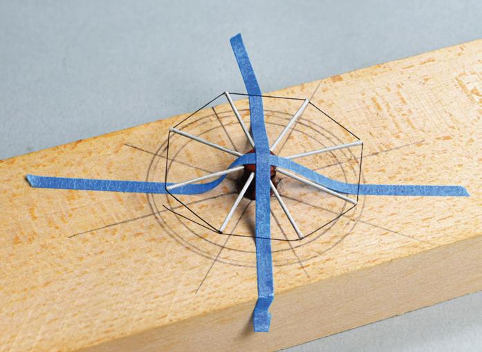
little brushing. For B-72 I usually use an old, worn brush without much shape. But here a fine tip was required, so I used a sharp new brush.
The Capstan
Abaft the mainmast stood the capstan. Its drumhead sported eight capstan bars, all of which were completely covered with a bloom more profuse than that on the cannon barrels. This bloom was not globular. It resembled the oxidation on the poles of a car battery or miniature white and tan popcorn. It looked fungal. Most of it scraped off easily, but not completely. I decided to remove the capstan bars for cleaning on the bench. I gripped one with tweezers and, sure enough, it moved a little. I kept wiggling and pulling gently — it’d have been catastrophic if the bar popped out and the tweezers recoiled into the rigging. One bar came, then another. They left clear, open sockets in the drumhead; later reinsertion would be easy. But, in mid-wiggle, one bar broke. The metal — it was copper or brass — had corroded to failure. In all, three broke. Making new bars would be simple, but I couldn’t get the stumps out of the drumhead with the capstan in situ. I decided to remove the entire capstan. It was glued in the deck and had to be pried out with a ⅛-inch-wide chisel. This tool normally feels tiny, but here it felt gigantic. I worked the edge under the capstan from four directions, prying gently. The glue gradually yielded and finally surrendered.
With even-pressured pulls, the stumps of the bars came out of the drumhead cleanly. I measured them: 0.025-inch rod. Because each socket had a different depth, I cut new brass bars of the same diameter to length after they were inserted. Then the keeper line was added. The complete capstan was disk-like. To install it, I held it with tweezers, turned it edge-wise, inserted it from aft to forward abaft the main rigging, lowered it to the deck while twisting it right-side-up,
sliding it forward, and pressing it into its socket on the hatch. It was dicey, but it worked.
Rigging
On McNarry’s models, systems of blocks and tackles appear operable. But how did he bore such tiny holes in such tiny blocks and reeve line through them? The answer is that he didn’t. In Shipbuilding in Miniature, McNarry revealed his process: “No knotting, bending or reeving is carried out anywhere…. There is consequently no strain on the masts, as each piece is quite rigid.” The real eye-opener was that this meant “that one rope on the prototype may be made of several pieces all assembled at different times on the model.”20 In other words, each length of line between a pair of blocks in a tackle was a separate piece of wire. Everything was illusion.
McNarry wrote that he fashioned most rigging from copper wire. I did not test it all, but this rigging appeared to be non-magnetic. The running rigging was painted light tan, and every bit was in good, solid condition. The standing rigging was another story. It was blackened, likely with aniline spirits as I suspected the cannon barrels were.21 On some smaller diameter standing rigging lines — say the size of topgallant backstays and smaller — a visible, flakey roughness had developed. Many, if not most, of these lines had failed. No lines that lacked the roughness had failed.
I experimented on fragments. By scraping, I found that they were not orange, like copper; they were silver. When I passed a magnet near drooping broken lines, they swayed. They were ferrous: not all McNarry’s rigging was copper! The smaller flakey lines were likely steel wire. Lines without the roughness displayed no magnetism. So, McNarry used both non-ferrous and ferrous wires in the standing rigging. And whatever coloring method he used seemed to have had a deleterious effect on the ferrous wire. More study showed that line failure was inversely proportional to its diameter.
70
tape points forward. The capstan bar at the upper right is still encrusted with reddish-brown globules.
Rigging the keeper line to the new capstan bars. Narrow strips of blue tape hold the capstan barrel in place in the jig.
Lines had parted in several ways, so I developed a technique to repair each. Most of my repairs utilized some form of glue splice. That is, glue was used to connect a line’s ends. One might think initially that fast-acting cyanoacrylate glue would be handiest, but with little or no working tack, they’d permit no flexibility or adjustment while working. I used undiluted fish glue. It was strong enough for this job, it had a lot of initial tack which held line ends together until they could be properly adjusted, it retained some flexibility later, and it was conservationally appropriate.
The lines easiest to fix were those that had broken near where they attached to something firm, like a spar or a block. For these, only one end had to be managed. More challenging were lines that had parted in midlength or in two places because both ends had to be managed concurrently.
A test was made for every repair. If the wire had simply parted, if both parts were still present, if they still met, and if they looked like they’d survive, I’d pro-
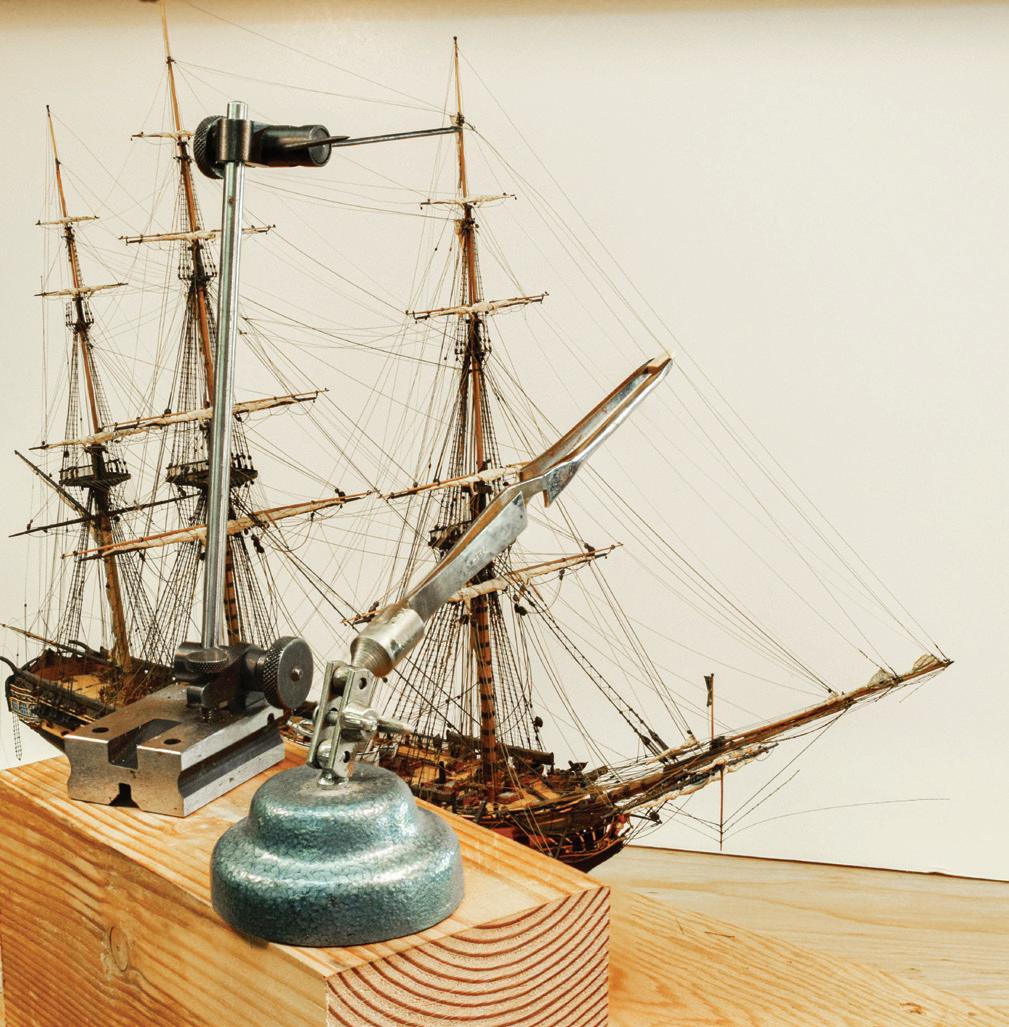
ceed. Some lines were short or light enough to permit gluing with no support. Others were longer and heavier and required support.
For this I used two devices designed for other work. The first was a third hand, a pair of reverse-action tweezers held in a universal clamp on a heavy base. The tool was marketed as a soldering aid for jewelers. The tweezers’ tips could be adjusted to any position, but they were rough. So, I glued to them a pair of softwood blocks the noses of which were beveled inward to form a shallow V for pushing a line into position without letting it slip away. The second device was a surface gauge, a probe on a shaft that could be screw-adjusted for height and reach. It is useful in ship modeling for striking waterlines. On the probe, I glued a brass hook for pulling lines into position. Together, the two devices provided precise control. When a repair was high on the model, they were raised on large wooden blocks adjacent to the model’s work base.


The surface gauge can be adjusted in many directions with great precision.
Far left. The hook on the on the upper extension of the surface gauge (A) pulls the fore royal stay to its place on the mast, and the third hand (B) supports the stay at its mid-length. Both devices are raised on a large wooden block, and white card behind the model makes seeing the detailed rigging easier.
Left. The mizzen royal mast had broken at the rigging stops. A stack of wooden blocks on each side of the model supports a cross beam (A) that holds the mast in position so the tweezers’ jaws on the third hand (B) can push the masthead forward during gluing. Notice that the lower edge of the beam has been scooped out so it does not contact the mizzen royal yard.
71
A B A B
After scripting my moves, I applied a tiny drop of fish glue on each free end of the line, working the ends until the drops grabbed each other. Then the third hand and surface gauge were eased into place. This sounds simple enough. But precision adjustment of the devices inside the rigging maze was nerve-wracking. It was nearly impossible to tell if lines passed in front of or behind one another. Spaces were extremely small and tight. To reduce eye strain, a white placard placed behind the model eliminated visual background clutter.
If a portion of wire was missing, I tried replacing it with a piece of disengaged original wire of the same size. Where necessary, I used new brass rod, which I have in sizes down to 0.004 inch in diameter. Below that, I used nickel-chromium wire, which comes spooled in sizes down to 0.001 inch. To clean the new material and give its surface some tooth, it was rubbed with 0000 steel wool. I painted the metal black with artist’s acrylic. Then it was cut to length and installed with fish glue.
Rigging repair was slow. Each glue splice had to sit overnight to let the fish glue fully set; during that time the model had to remain stationary. No less than three dozen lines required at least one glue splice, and many required two.
I found at least one previous repair. A stay had parted near a mast. It had been repaired with a glue splice, but the ends of the stay didn’t quite meet. This meant the stay was too slack; it draped too low, and that wouldn’t do. The old repair had to be undone. First, I used a knife blade heated in a candle flame, but the old glue did not react. But a drop of water applied to the old glue worked in a few seconds. A new glue splice was made that joined the lines properly.
The Display Constitution was mounted on a pair of cradles fixed to a plinth that mounted on a base. The plinth looked heavy but was actually a lightly constructed inverted veneered
box. The base was a shallow plywood tray, with a veneered frame. The base was screwed from the underside to corner blocks glued inside the plinth. The plinth was ¼ inch smaller than the inside of the base, all around. In the gap, a glass vitrine stood on a gasket made of rubber and felt strips. The vitrine’s exposed vertical and upper edges were veneered to resemble wooden posts with a top frame. All the veneer was rosewood. Originally, the vitrine had been secured to the base with twine threaded through holes in the base and the bottom of the vitrine in a method peculiar to McNarry.22 There were three obvious problems with the display. First, there were many blemishes in the veneer on the base and plinth. Most reflected the locations of internal fasteners. Second, the veneer on the plinth was severely rippled and was separating from its substrate. Third, the veneer moldings on the vitrine’s edges were coming off. For this job, I retained the services of professional furniture conservator Melissa Carr of Masterwork Conservation in Arlington, Massachusetts. Most of the following was taken from Carr’s treatment report for this job.23 She treated each of the three components separately.
Carr filled the dents and splits in the veneer on the base with a product called Modostuc, a dense, low-shrinkage paste that uses a PVA as a binder and calcium carbonate as a filler. She in-painted treated surfaces. An engraved brass nameplate identifying the model and its builder was mounted on each side of the base. One plate had separated from the four pins that held it to the wood. On its backside was scratched “C IV,” another of McNarry’s markers that this was his fourth model of Constitution. Carr removed old varnish from the plates, polished them with Nevr-Dull (see Case Study 12 of Dunderberg), lacquered them, and reseated them with B-72.
On the plinth, many nail heads had pushed filler through the veneer, the veneer was detaching from the substrate, and varnish was peeling from the veneer. Carr attributed the movement of the nails to wood de-
72
hydration. She lifted the split veneer, removed the old putty, replaced it with Modostuc, laid down and glued the splits, and then in-painted. Veneer separation was mostly on the ends of the plinth where its grain was at odds with the substrate. Carr released the veneer with a water and ethanol solution, pulled the veneer down tightly over the edges, and fastened it with fish glue. The substrate had shrunk enough to let the veneer extend 1/16 inch below the bottom edge. She filed off the overhang. Regarding the varnish, Carr wrote, “few finishes adhere well over time to the naturally oily surface of rosewood. Compounding the problem was the rotary-cut process of producing the veneer that creates microscopic cracks in the thin sheet. These are failure points for the finish and were visible as ridges.” She removed the old varnish “mechanically” and replaced it with shellac.
The vitrine presented lesser issues. Carr cleaned the glass with a 1:1 solution of water and denatured ethanol. Loose, non-structural veneer was resecured with fish glue.
The Real Problem and Its Solution
Lining the perimeter of the inside of the base were strips of rubber along the ends and felt along the sides. They cushioned the bare, sharp bottom edges of the glass vitrine. They also acted as a gasket to create a “sealed chamber.” Usually made by McNarry of a plasticine bead or a felt strip, he intended that such gaskets protect the model from dust.24
The downside was that the seal trapped off-gassed compounds inside the vitrine. Carr said that sulfur from the rubber gaskets was a notably “aggressive degrading agent for the metal components of any object” and “a particularly bad actor for lead…. Materials such as vulcanized rubber containing sulfur should not be used in contact with objects and should not share the same airtight…enclosure. Sulfur compounds are known to discolor, corrode and/or weaken some objects.”25 She had
the sulfur content of the rubber portions of the gasket analyzed by a colleague in the conservation laboratory of a Boston museum. The result was that she had “never seen such a strong positive reaction for sulfur.”
My guess is that McNarry didn’t use lead in his models because it doesn’t work to his fine tolerances. However, he did use a wide range of materials and finishes, and despite what he may have written, we have seen that he wandered from his own stated preferences, as many of us do. Although I have suggested that McNarry colored the cannon barrels and rigging with aniline spirits, I don’t know that he did. There is no doubt that the cannon barrels, the capstan bars, and some finer standing rigging were suffering an attack on their surfaces. This begs the question: were these three areas colored with a lead-bearing paint? If it wasn’t this, then the indication is strong that these items alone were finished with something that was unusually susceptible to the caustic sulfuric atmosphere emanating from the sulfur-bearing rubber portions of the case’s cushioning gasket.
Carr removed the original rubber and felt gasket material from the display base. Then, knowing that ventilation helps prevent atmospheric issues inside cases, she made a new gasket that cushions the bottom edges of the vitrine and allows air to circulate. She cut a sheet of ⅛-inch-thick Volara, a closed-cell polyethylene foam, in such a way that it supports the corners of the vitrine for about 3 or 4 inches on each side and end. This left most of the lengths of the sides and ends suspended about ⅛ inch above the bottom of the base. And this, in turn, left plenty of space for air to pass in and out of the case.
This seemed like a simple solution to a complicated problem, and we hope that it was. I have experience with five other McNarry models but was not able to examine how the cases were sealed. Time will tell if this model of Constitution stays healthy. The concern, however, is about McNarry’s hundreds of other models. Are they also trapped? ¯

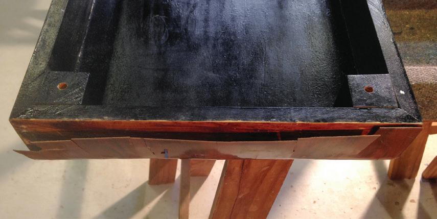

73
Two of many places where filler in the countersinks for nail heads (arrows) had pushed out enough to fracture the rosewood veneer on the rounded edge of the plinth. The nails hold together structural parts of the plinth under the veneer.
Because the structural parts of the plinth shrank with dehydration and becasue glue doesn't do well with rosewood, the veneer lifted away from the plinth’s structure. (Photograph by Melissa Carr)
Part of the new Volara insert that cushions the vitrine’s bottom edges and allows passive ventilation. (Photograph by Melissa Carr)
Case Study 6
Unidentified
about 1800: French 70-Gun, Third-Rate Ship of the Line
Miniature Rigged, Full-Hull, Prisoner-of-War Model
When this model arrived in 2013, not much was known about it. By noting the deck arrangement and counting gunports, it could be labeled as a 70-gun third-rate ship of the line. I suspected the vessel’s specific identity would be difficult to establish, but that it would be possible to determine its era and nationality.
I e-mailed a group of photographs of the model to Grant Walker at the U.S. Naval Academy Museum. He recognized a set of markers that did the job. Walker noted the following: The spanker set on a boom and gaff (this dates onward from the 1770s); the gangboards were flush from the forecastle to the quarterdeck (onward from the 1770s); the boat beams across the well (the open area between the gangways) were permanently fixed (onward from the 1780s); the well had rounded corners (French, onward from the mid-1750s); the fore jeers capstan mounted on the forecastle (purely French); scuttlebutts were fitted at the base of the mainmast (only on French prisoner-of-war models); the bowsprit had a dolphin striker (not before the 1790s); the built-up quarterdeck bulwarks were squared off (onward from the 1790s); and the bottom was shown as coppered (onward from the 1770s). Walker concluded that this evidence points to

a French prisoner-of-war model representing a vessel of the 1790s.26
The model was fitted with two British flags, a white ensign at the peak of the gaff and a long commissioning pennant at the main truck. This was typical of prisoner-of-war models that were based on French vessels, but on which British flags and names were frequently displayed.
Taffrail to figurehead, the hull was about 3¼ inches long and below the waterline it was solid copper. If it was a single block, the keel, stem, and sternpost, which were discrete pieces, were let into a rabbet along the centerline. If the hull was two halves, they embraced a copper backbone. Either way, rivets along the deadwood held things together. Wooden upper works were attached to the top of the copper block. I couldn’t determine at what height the copper stopped. However, when looking through the open chase ports on the gun deck, daylight was visible ahead, and the view forward through the upper deck stern gallery felt almost expansive.
The jibboom, main topgallant mast, and gaff were broken. The rigging was made of the lightest-weight line I had ever seen and unbelievably fragile; many lines had parted. The largest deadeyes were less than 1/32 inch in diameter, were pierced to scale, and lanyards ran through them. Repairs to two spars and most of the rig-

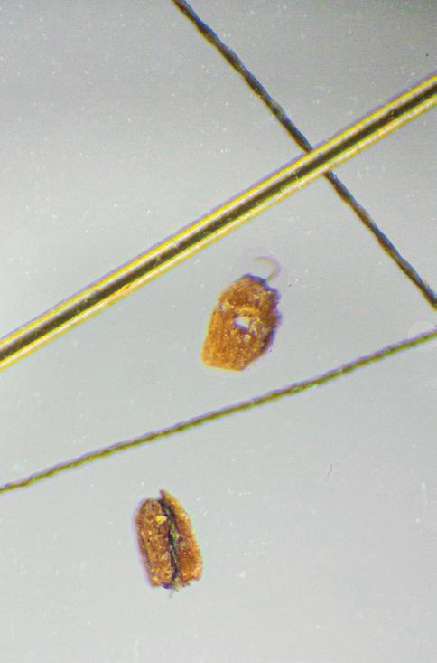
74
Right. This miniature model has a solid copper bottom. Note the size of the block (arrow). That is not a trick ruler. Center. A Canon 5D Mk II digital single-lens reflex camera mounted on an AmScope binocular microscope.
Far right. Photomicrograph of a 0.003-inch brass rod (arrow), blocks, and lines. To conserve space, the lower block was digitally moved from another area of the image; its size was not altered.
ging was straightforward but delicate work for which I used fish glue. An intermediate hand had repaired the gaff crookedly and had left no slack in its rigging. Some lines had to be sacrificed to realign the parts of the gaff. At this point things became interesting.
When they were on the model, I hadn’t considered the actual size of the blocks and rigging line. But when they were on the workbench, I realized they were really small; I wanted to quantify their sizes. The two blocks I removed were too tiny to measure with a micrometer because the tips of my finest tweezers got in the way, and the two sizes of line were too fragile. I enlisted the aid of Scott Bradner, a ship-modeling colleague in Cambridge, Massachusetts, who has a binocular microscope on which he mounts a digital camera.
We considered several ways to measure the specimens. The simplest was to prepare a microscope slide with both blocks, both line samples, and a length of something whose size we knew. This was 0.003-inch-diameter brass rod. Scott made a photomicrograph. Using a micrometer to measure the rod and specimens in a greatly enlarged print of the micrograph, the blocks, which were nearly the same size, were calculated to be about 0.011 inch long and 0.007 inch wide. The one measurable sheave hole was irreg-
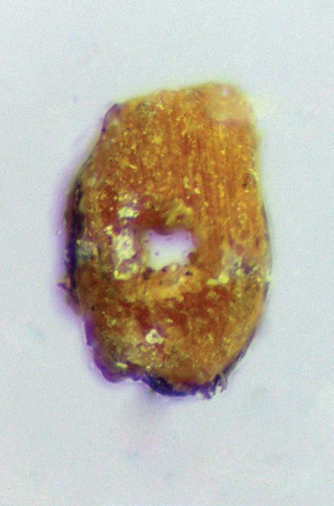
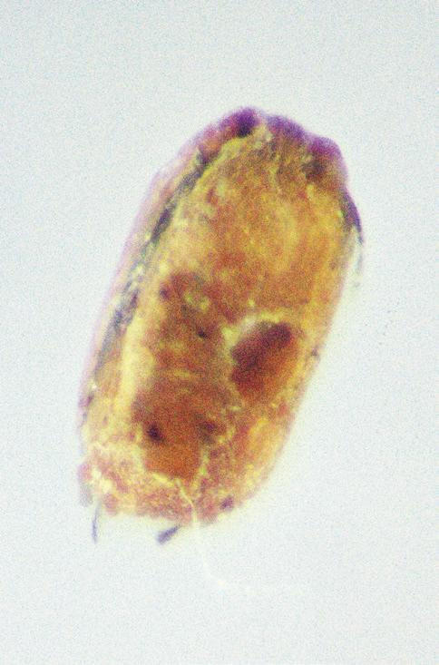
ularly shaped and was about 0.0014 by 0.0019 inch. There were remnants of strops in grooves around the blocks.
What about the lines? In the micrograph, it appeared the larger line would just fit through the sheave hole in the block. When calculated against the brass rod, the larger line was about 0.00115 inch in diameter and the smaller line was about 0.0008 inch in diameter. During subsequent microscopy, we determined that both lines had been twisted from two strands. The larger sample’s strands were half the diameter of the line, or 0.00057 inch, and those strands’ three constituent fibers were about 0.00027 inch. (In three-strand line, one strand equals the diameter of the line times .462.)
At this point, we deemed it easier to convert the measurements to numbers with fewer zeros. One micron equals 0.000039 inch. So, it turns out that the larger line’s 29-micron diameter was twisted from two 14.5-micron strands that were twisted from three 6.7-micron fibers. This was consistent with the 5- to 10-micron diameter typical of silk fibers produced by the Bombyx mori, the domestic silk moth.27 The smaller line was a simple twist of two fibers. I had never imaged working with rigging whose size was easier to gauge in microns than inches! ¯

Far left and center. The two blocks enormously enlarged.
Left. The larger and smaller silk lines showing their make-up.
Below. The larger silk line against a micron scale.

75
Case Study 7
Unidentified
about 1800: French 90-Gun, Second-Rate Ship of the Line Contemporary Full-Hull, Prisoner-of-War Model
This model was built in the roughly standard format for bone models of the prisoner-of-war genre. The model represented a three-decked ship of the line of about 90 guns. No name was associated with the model, but the French Tricolor flew from the mizzen peak and a long French pennant streamed from the main truck. The hull measured about 5¼ inches long and supported a 9½-inch-long rig. This was small, but not unusually so. The rigging was fine and complex. The model was supported on an exquisite early straw work base.


When it had been packed for a transatlantic flight, the case’s vitrine had been removed from the base and inverted. The model had been nested in foam inside the vitrine, and the case’s base had been placed on edge outside the vitrine and against an inside surface of the heavy cardboard shipping carton. No packing protected the model from above. Someone, I was told it might have been a customs agent, had carelessly reached into the carton and, in so doing, had crushed the model’s upper masting and rigging. This would not have happened if the vitrine had been right-side up protecting the model.
My commission in 2014 was to interpret the mess for insurance purposes. I was to determine which damage resulted from the modern accident and which issues, if any, might have occurred earlier. For the latter, I was to determine which had been repaired by a previous hand and if those repairs had failed. Oh, yes: I was also to clean and repair everything.
When faced with a complex job, I first familiarize myself with the model — its construction, level of detailing, fragility or robustness, finish, dirtiness, and
stability. During this cautious period, I assume everything can fail. I probe softly, usually with gentle-action tweezers.
In this case, I learned recent damage was restricted to the region above the fore and main topmast trestletrees-crosstrees units. (A feature of smaller prisoner-of-war models was that the topmast trestletrees and crosstrees were generally fashioned as a unit from a single flat piece of bone.) The fore and main topgallant masts and many related lines were broken. I suspected the downward crush on the forward-leading stays had jerked the bowsprit upward sharply enough to break the weakest rigging components beneath, namely the bobstay lanyards and the gammoning. A few lines not associated with the recent damage had parted, but most rigging was intact and fairly strong. Many deck details were loose, but none were broken.
Though I knew it would be removed eventually, I left failed rigging in place for as long as possible. The longer I work around broken rigging, the more likely I am to remember its characteristics. The more I remember, the less I must record.
I cleaned the model with the enzyme technique. The grime came away easily with a single application. Cleaning couldn’t be finished until I made decisions about specific damage. Where had the main and fore topgallant masts broken, exactly? How would I return them to their original positions? How much rigging could I save? How much did I have to remove?
The main topgallant mast was broken above the topmast’s cap. The surfaces of the break did not mate. This meant that a section of the mast was missing. By lifting the mast’s upper portion until its backstays, which were still sound, were taut from the channels, I estimated the loss was about ⅛ inch.
On most small prisoner-of-war models, standing and running rigging converged in a messy stack looped and tied around the mastheads above the lower tops and above the topmast trestletrees-crosstrees units. On this model, the stack also seemed to embrace the por-
76
The model after removal from its packing.
The worst parts of the wreckage were the broken spars and old globbed glue at the main topmast head.
tion of the heel of the topgallant mast below the cap, a place rigging was never found on real ships. Projecting above the stack, the topmast head and the topgallant stump remained in the cap. I tried wiggling the stump, only to discover that the topmast head and the topgallant stump were apparently fractured inside the stack of fiber rigging.
Because the break was inside the stack, there was no firm foundation for reconstructing the topgallant mast. I soon realized that someone else had faced this same problem earlier. The previous hand’s solution for repairing the two broken pieces was to saturate the stack with glue and to construct a large blob of glue, which I had initially mistaken for rigging, around the lower end of the topgallant mast.
That blob had to go. I considered softening it with a solvent but did not want to make matters worse by creating a gooey mess. Employing a mechanical answer, I twisted the point of a No. 11 blade between the dried glue and the bone surface of the trestletrees-crosstrees unit. To avoid stressing the rigging, I grasped the trestletrees-crosstrees unit firmly with one hand while working with the other. To minimize movement, I braced my hands on large wooden blocks placed on the workbench alongside the model. Gradually the glue chipped away. About an hour was consumed in this delicate step.
With the old glue gone, the topgallant mast stump below the cap came free. A tiny fragment of the heel

filled and remained stuck in its socket in the trestletrees-crosstrees unit. This shard had to come out, but it was too short to grip. Fortunately, it protruded about 1/64 inch below the unit. I placed one tip of a strong tweezers on the top of the unit and the other under the shard below. When I compressed the tweezers, the shard was forced up and liberated.
I then had the topgallant mast in five fragments, one of which was missing. At the doublings, the spar was about 3/64 inch in diameter. I could repair something this small with a coaxial pin. But, at the higher breaks, the diameters were too small to pin, and I would still have to grave in new material for the missing length. I decided to make a new topgallant mast.
Because of the embargo restricting traffic in elephant and marine mammal products, I used unregulated mammoth ivory. I ripped a 3/64-inch-square strip a few inches long on the Preac saw, marked off the overall length of the new 1⅝-inch-long topgallant mast, and tapered it on the table sander, keeping it four-square. I made a small jig to steady the tapered strip, then filed it round until the original topmast cap fit snugly at the right height. I smoothed the spar with 600-grit sandpaper, parted it from the strip, and filed the heel to step in the socket in the trestletrees-crosstrees unit.
Meanwhile, the upper bit of the topmast head was stuck in its mortise in the cap. Not wanting to fracture the cap, I soaked the pieces in water. This softened the glue and released the bit of mast.

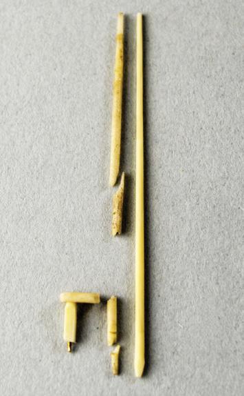
Far left. The new main topgallant mast is being steadied in a groove in a wooden block while filing the taper to shape.
Center left. Fitting the original cap to the new topgallant mast.
Near left. The new upper part of the topmast head (arrow), four fragments of the old topgallant mast, and the new mast. Note the brass pin in the bottom of the new topmast head.
77
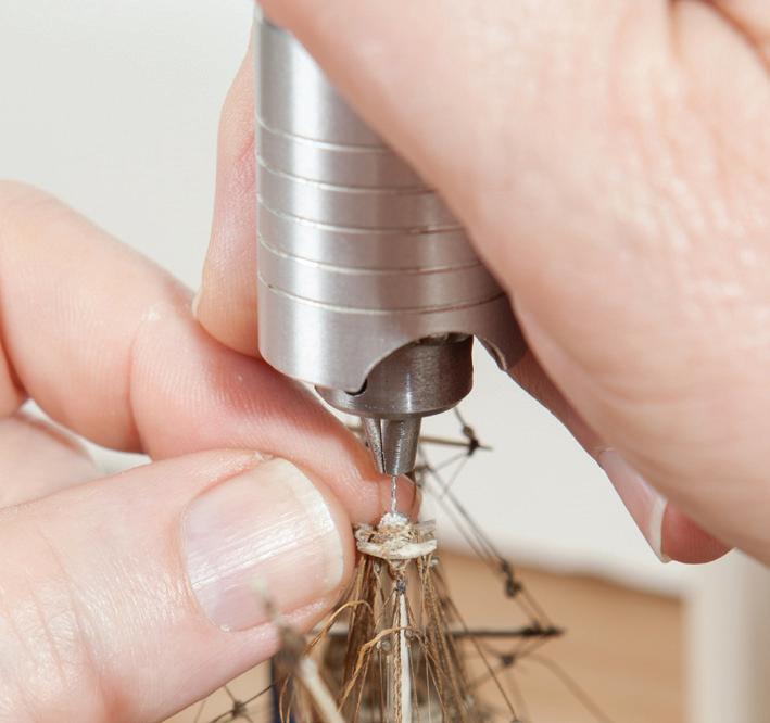
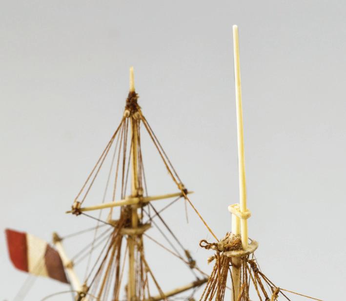
It turned out that the masthead break was just even with the top of the stack. The break’s mating surfaces were too ragged to drill well-aligned holes for coaxial pinning. If I smoothed both sides of the break enough to bore concentric holes, the head would be too short. So, from the mammoth ivory, I fashioned a new extension for the head. I pinned it to the topmast head’s stump, which I had smoothed to the level of the top of the stack.
Next to the model’s original aged bone and ivory, the new pieces were garishly white. They had to be muted. If painted with a solid color, they would still look out of place. I made a palette of four acrylic colors: titanium white, unbleached titanium white, burnt umber, and No. 6 neutral gray. The trick was to brush on a loosely mixed wash so all four colors influenced the appearance. I practiced on a piece of scrap.
The broken upper portion of the fore topgallant mast was trapped by its rigging but leaned precariously to starboard. As on the mainmast, this topmast head and topgallant mast had broken within the rigging stack on the trestletrees-crosstrees unit. But there was only one break in each part; no material was missing. This was all recent damage. I hoped to stand the mast upright without having to remove many lines. I considered flooding the area with glue, but then I’d have done no better than the previous hand on the main topmast. When I popped the topgallant shrouds, which were intact, into the notched ends of the crosstrees, they supported the mast properly and securely. With no glue or pinning, this was a simpler fix than I had anticipated. At this point, I understood the order of damage to the model. At the foremast, I assigned the breaks in the topmast head and topgallant mast to the recent poor handling. At the mainmast, the impact caused the breaks in the topgallant mast above the topmast cap. But the breaks within the rigging stack were older. All the damage to the standing rigging at and above the trestletrees-crosstrees units on both masts and to the running rigging associated with topsail and topgallant yards was the result of the impact. The impact was re-
sponsible for all the parted rigging under the bowsprit. The impact was not responsible for any of the loose fittings found around the model; these had come adrift because of glue failure over two centuries.
Before access to the decks was hindered by new rigging, I reinstalled the eighteen or so parts that had come adrift. None were subject to stress, so they were secured with fish glue.
Rigging
About sixty individual lines had to be repaired or replaced alow and aloft. A few warrant comment. I admit that I am not always confident about managing some aspects of model work. When faced with the small size and congested rigging on a model like this, I must overcome a sort of “rigger’s block.” I find that the best policy is to start with the largest components. This teaches me the muscle tensions that can be exerted on a given model. As details become smaller, those tensions are adjusted appropriately.
When sorting out the rigging, I noticed that some blocks were missing. Several, but not enough, were lying in the model. Fortunately, I had a little jar of random parts left over from other jobs. Magically it produced some tiny old blocks that were perfect for this job.
The smallest blocks were about 3/64 inch long. I turned them into pendants and seized them to spars in the normal fashion. In many instances, strops had parted, but the lines running through the blocks were sound. For these, I had to remove the strops without breaking the running lines. I couldn’t hold the tiny blocks in my fingers. To help, I used the third hand with the wood-padded jaws. With the third hand grasping the running line behind a block, I used a No. 11 blade to sever then peel away the failed strop. Later, I used the same device to hold the blocks for restropping.
Most of the fore and main topmast backstays had parted. I was able save them all with glue-splices at their eyes aloft. I used undiluted fish glue.
78
Drilling a 0.012-inch hole in the stump of the main topmast for a brass pin to repair the head. The hand holding the flex shaft is braced on a large block. (Photograph by Dawn Rabinowitz)
The new main topmast head and topgallant mast temporarily in place. Notice how much whiter the new spar is than the original ones.
As on many prisoner-of-war models, the fore and main lower yards were equipped with yard tackles. They were rigged outboard and, by means of long pendants, were secured to eyes in the baseboard. Their purpose was to give the model transverse stability in its cradles. On some models, a boat was suspended in the tackles or pinned to the baseboard so the tackles looked like they were doing something practical. Some yard tackles on this model had failed. These lines were tentatively repaired early in the game to create a square and solid foundation for re-establishing the rigging geometry farther aloft.
Squaring the yards was tricky because multiple adjustments were required as I overhauled new lines, and because I didn’t want to break original lines. All three of the all-but-weightless topsail and topgallant yards were held down, against the upward pull of their lifts and halyards, by lines not found on real ships I long ago dubbed gravity enhancers. These lines, rendered as inconspicuously as possible, are contrived to pull against spars to help other lines and tackles appear taught and weight-bearing. Here, the starboard main topsail yard gravity enhancer was gone, so it was replaced.
Many rigging lines leading down from aloft had been belayed outboard, to deadeye strops under the channels. This was not the way things were done on a ship, but, because the original modelwright had rendered them this way, I preserved the practice.
Installing running rigging on a square-rigger model is visually taxing, especially for lines passing from aloft to the deck through increasingly dense mazes alongside masts. On actual ships, it’s important to lead lines so they chafe as little as possible. On models, chafe isn’t much of a problem, but aesthetics are; lines twisted around each other are unsightly. I work hard to assure lines lead fairly.
I do this in two ways. The first involves procedure. To reeve a new line down a mast, I study the geometry of the existing rigging to learn the path the line must follow. Starting at the top, I take the line’s
end in a tweezers and lead it down until the fair passage of the tweezers is hindered. Then, below the obstruction, I bring in a second tweezers with my other hand, grab the line, and repeat. The trick is to not pull all the line through any given block or fairlead until the leading end is led through all of them. When the lead is correct, I overhaul the line. This reduces the chance of snagging big loops of line on fragile things. When using tweezers in close quarters, like within the rigging around a mast, make it a practice to keep the tweezers’ jaws pinched shut until they are immediately adjacent to what you want to grab. This cheap insurance protects fragile rigging.
The second involves color. If all the rigging is about the same color, or density of color, it is tough to see if a new line is in front of or behind others. As a foil for this, I generally install running rigging when it is light in color. Then I color it. Other modelers may think me mad, but it works for me.
Each new line requires a bitter end long enough to manipulate during leading, adjusting, and belaying. Lines are tensioned to look taut as if they are bearing weight. The spars they control must be square — meaning they must be horizontal when viewed from ahead and perpendicular to the centerline when viewed from above. Tackles must be free of twists. Knots and belays must be firmly set. Unsnipped bitter ends accrue into tangles that obscure visibility and accessibility. Occasionally, it’s necessary to decide that a group of lines is finished so they can be cleaned up and snipped. This event usually coincides with the completion of work in each area. On this model there were three such moments. The first was at the completion of work around the bowsprit, the second was when rigging for the main topmast and topgallant yards was complete, and the third was at the end of the job. (An irony to rigging small models is that the amount of line ending up on the model may be far shorter than the scrap cut away after rigging it.)


79
The third hand with gentle wood tips holds a gaff vang so its fiddle block (arrow) can be given a new strop without stressing the line.
The last batch of new rigging has been repaired and colored and is waiting to have the long white ends snipped off.
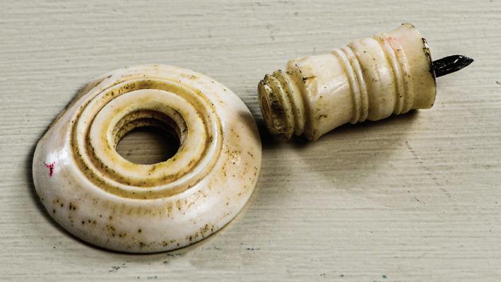
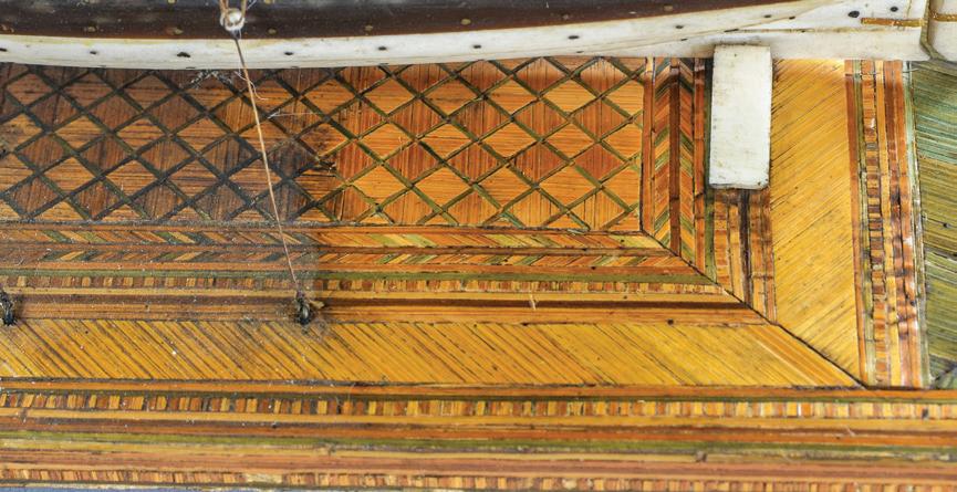
In the maritime world, it’s considered lubberly to let lines drape over a vessel’s side. There are good reasons why this is a bad habit, but the best is that it just looks sloppy. Never let the working ends of new rigging lines extend over a model’s side far enough to drag on the workbench. If the model is moved, an end can catch under the base and jerk something fragile to the point of failure. Leave lines long enough to adjust, but trim them so they hang just clear of the bench.
Have a pair of scissors dedicated to snipping. They should be pointed to access narrow spaces alongside other lines, and they must be exceedingly sharp so they snip the line on the first try and leave the end crisp. Be prepared for the inevitable! At some critical point, you will snip something you had no intention of snipping. You will have to go back in and fix it. You will not suffer alone; we have all done this.
As lines are snipped, something magical happens. The model begins to look increasingly like a ship because the final vestiges of the hand of the modeler are being removed. For me, when the last line is clipped short, the model seems to pop into focus as a finished ship. I love this moment.

The Baseboard
The baseboard was a simple 3¼- by 7½-inch wooden plank of pine or a similar softwood. Each corner was supported by a two-part leg assembled from a turned post that screwed into a turned pad or foot. The threads were hand-cut, and the parts were bone or ivory. Each leg fastened to the underside of the base with a steel pin. Directly above, each corner was adorned with an ivory finial. The plank served as a substrate for a covering of polychromed straw work. The straw work was fine in detail and quality. It was in reasonably good condition. There were few losses, and some bits of straw were only slightly wrinkled. All parts of the baseboard responded well to the enzyme technique, although the straw work required a couple of applications.
Straw work as a decorative motif dates from at least the seventeenth century. It is attractive as a medium because it is easy to dye and is durable. Its bright surface can be attributed to silica and wax inherent in the straw. Straw from several grains has been used, but winter oats seemed to have been the most suitable.28
Straw work amazes me. The delicacy and rigor of its geometric patterns are startling, especially when it is contrasted with something as abstract and complex as a ship model. I happened to photograph this model from directly above, and, looking at the image, it occurred to me that the straw work on the baseboard was particularly fine. I don’t know if anyone has ever analyzed straw work on ship model displays. If so, then here is an addition. If not, here is a start. This sort of exercise is only for the truly whacko. In Photoshop, I traced the straw work from the overhead photograph as accurately as I could. It seems that ship modelers like to count things, and I am no exception; there were roughly 4,980 pieces of straw in this composition, not including those on the vertical edges of the baseboard. And this is just a small example! ¯
80
Above. The straw-work to the right has been cleaned with the enzyme technique. The line leading to the base is a yard tackle that steadies the model in its cradles.
Below. The graphic interpretation of the straw work base.
The turned pad and post of a leg for the baseboard were joined with hand-cut threads (arrow).
This ship-rigged corvette was built in Maryland in 1810 and originally named Hannibal. She was captured by the Royal Navy in a chase action near Bordeaux, France, during the War of 1812, renamed Andromeda, and sold in 1816. Lines were taken off by the Admiralty, and the drawing may be viewed at the Web site of the Royal Museums Greenwich.29
The vessel’s dimensions were reported by David Lyon as 135 feet 6 inches in length on deck, 108 feet 6¼ inches in length on the keel for tonnage, and 37 feet 5½ inches in molded breadth. She measured 809 tons.30 She was fitted with twenty-two 32-pounders and two 12-pounders. This matched the arrangement on the model with one long 12-pounder right forward and eleven short 32s on each side. Happily, both the plan and the model showed that the steering arrangement was a tiller rigged to a wheel.
The Model
It’s always interesting to calculate a model’s scale. For Andromeda, we only needed to use the length on the
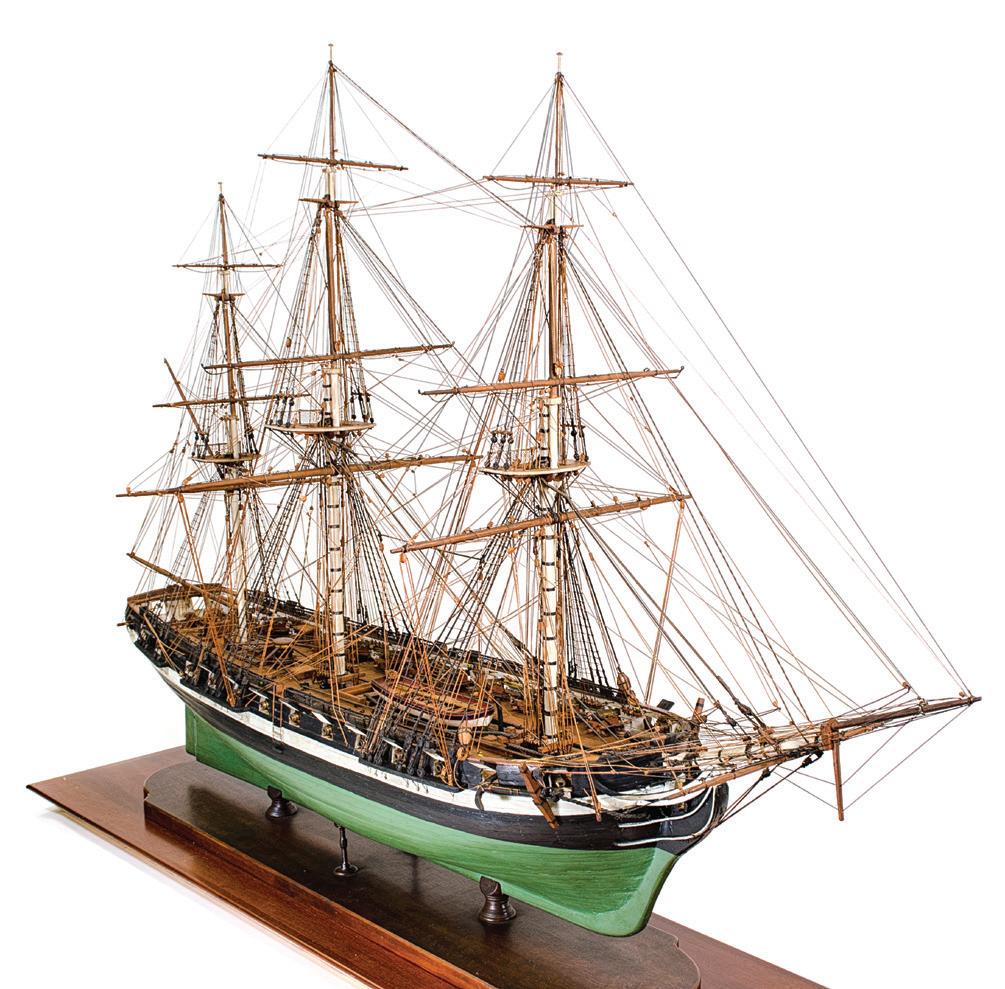
range of deck. Lyon described this as being measured from the “further edge of the rabbet cut into the stem and stern posts.”31 Always a little tricky to measure accurately on a model, this length on Andromeda was at most about 36 inches, but, because the deck terminated abaft the rudder post, it could have been slightly less. When the length on the range of deck was worked through the most probable scales, such as 1:64, 1:48, and 1:32, it became apparent that the model’s scale was 1:48.
Case Study 8
Andromeda ex-Hannibal
1810: British (ex-American) 24-Gun Corvette
Modern Rigged, Full-Hull Model
The model was covered with loose dust. In 2013, I went over everything lightly alow and aloft with a soft, ¾-inch nylon brush, starting the dust and sucking it up with a vacuum as I progressed. Then I applied the enzyme technique in the usual fashion.
The Helm
The steering wheel was in rueful condition. I wondered if it was the victim of a guest at a cocktail party. The wheel was boxwood. A one-piece turned rim was pierced for eight round spokes. The spokes socketed into a boxwood hub that was securely glued to the shaft of the barrel. The forward end of the shaft was supported by a two-legged pedestal that stood on an athwartship base that, in turn, fit into a trough in a boxwood deck grating. The base was secured with five steel pins, which

Far left. The finished model.
Left. The broken steering wheel. The rim is split (arrow), and all the spokes have come out of the hub. The two upper-left spokes are broken just inside the rim.
81


The post, pedestal, and steering wheel are the three main components of the helm.
seemed excessive. The shaft’s aft end was supported by a simple post that stood in a socket in the same grating. The steering rope took five or six turns around the barrel; it was slack. By how much its color differed from other rigging, it was easy to see that the steering rope had been replaced by an intermediate hand.
On one side, the wheel’s rim was split along its grain and in line with a spoke hole. That spoke and its two neighbors were broken where they emerged inside the rim. All the spokes were adrift. The entire system was rigid. To repair the wheel in situ would have meant working within the rigging and without benefit of a flat surface for aligning the spokes. Thus, it was easy to decide to repair the wheel on the workbench.
The wheel came off its hub easily because of the broken spokes. To withdraw the five pins that held the pedestal to the grating, I used a pair of nippers with sharply pointed jaws. I laid a block of scrap wood on the grating to protect it and to raise the nipper jaws to the height of the pinheads. I gently worked the jaws under the head of a pin then rocked the nippers back, levering the pin out as if I’d been pulling a 10-penny nail with a claw hammer. Here I used several short grabs. The fifth pin was between the pedestal’s legs; the space was too restricted for the nippers, so I used curved tweezers. The post was stuck but not glued in place, so I gently wig-
gled it free. All this released the barrel’s axle from its hole in the post. Then I unwound the steering rope.
To rebuild the wheel, a jig was required that had to accommodate the rope drum and the pedestal, but not the post. There had to be a surface at the plane of the aft side of the wheel so it would be, when reinstalled, perpendicular to the drum’s axis. I knew I’d spend more time making the jig than I would using it, so it was unrefined. In a block of scrap pine, a hole was drilled for the drum. A notch in the block registered the pedestal’s base so it would not rotate. Two flanking pieces were glued on the block to provide a plane for working the spokes back into the hub. When the spokes were right, I flowed a solution of PVA glue diluted about 30 percent in water into the complex joints around the hub. Excess glue was daubed away with a cotton swab.
The helm’s components were reinstalled in the opposite order of their removal. Wrapping the steering rope around the drum and getting the turns properly laid was, I thought, going to be frustrating. The process was made simple, though, because the rope hadn’t been taut, and it had a good memory of its own shape. I considered improving the rope’s looks by making it tighter, but its bitter ends were glued securely in holes in the tiller. I could not easily loosen them and certainly did not want to break them. So, I left it slack. ¯
Right. Because the wheel's hub could not be removed from the drum for the steering rope and the pedestal, the jig for repairing the wheel had to accomodate the pedestal and provide a plane for the wheel's rim. Far right. The repaired wheel from aft. The ends of the steering rope were secure in the tiller, so the slack that is apparent on the drum was not removed.


82
Removing a pin. The curved tweezers are braced on a block of wood (arrow) to avoid damaging the grating and to provide better leverage.
nez was a ship-rigged ocean carrier. She was built in 1829 at Haverhill, Massachusetts, a mill city at the head of the Merrimack River’s tidal reach. With register dimensions of about 112 feet in length and 350 tons, Inez was typical of thousands of vessels born along the river prior to the enormous escalation of vessel size in the mid-nineteenth century. Inez’s first registration was at Newburyport, Massachusetts, near the Merrimack’s mouth, on 1 January 1829. Her principal owner was Micajah Lunt. She was registered again in 1837, but her fate is unknown. She was likely gone, however, by 1851 when some of her owners registered a new Inez, a ship of about 700 tons built in Newburyport.32
This, the builder’s half-model for Inez, now resides in Newburyport’s Custom House Maritime Museum.33 The model is as characteristic of its era as was the ship built from it. The model was carved from an assembled block of seven horizontal, alternating pine and mahogany lifts, with pine bottom-most. The lifts were tenoned together vertically. The height of the planksheer was defined with a painted black band. Pencil lines marked vertically on the model’s centerline plane indicate that the model was measured for lofting the vessel. Now-empty screw holes indicate that the model was once mounted on a backboard. No evidence suggests that, after her service as a design tool had expired, any decorative work (such as a stem, keel, or rudder) was added other than the vessel’s name, year, and tonnage. Many years ago, the model had been disassembled so it could be displayed with its lifts separated. The backboard went missing. Worse, the tenons that secured the lifts together and that were integral parts of the model as a document, were lost.
In 2020, I was asked to replace the model’s tenons so it would be whole, again. This commission was accepted enthusiastically because I was eager to work with models and vessels of Inez’s type and vintage: I wanted to hear everything this model could tell me. The job provided opportunity to learn exactly how a
builder’s half-model was held together without any metallic fasteners or adhesive.
Inez was swathed in a blanket for the short ride to my shop. The two missing tenons held the lifts of the 32⅛-inch-long model together because they were tapered in both width and thickness. They passed upward, through mortises cut in the seven lifts. Their wide ends were faired with the model’s shaped bottom. The tenons tapered from about ½ by 23/16 inches at their lower ends to 3/8 by 115/16 inches where they exited the top lift. The tenons fit in the mortises precisely enough to eliminate movement in all the lifts. Locations for each mortise had been scribed on both surfaces of each lift. I suspect the mortises were cut with a chisel. Interestingly, the tenons’ vertical surfaces were not parallel to the model’s centerline plane. I was glad I did not have to cut new mortises — I had the easy end of the job.
Case Study 9 Inez
1828: American Merchant Ship
Contemporary Builder's Half-Hull Model
Fine old white pine was selected for the new tenons. I ripped it to be about 1/32 inch wider and thicker than their largest dimensions. On the bandsaw, the thickness taper was resawn into one side of each tenon. The sawn surface was smoothed on the table sander and refined until it fit snugly. Then the taper of the width was cut and fit. Initially, the tenons were left long. They’d be cut to length after they fit properly. When driven into the hull, they should draw the lifts together. A small wedge-shaped toggle was installed through a mortise through the top of each tenon. The 1⅛-inch-long wedges were mahogany and tapered slightly from their ¼- by 3/8-inch larger ends. Each wedge mortise was cut by predrilling a hole, inserting a jeweler’s saw blade in the hole, cutting the round hole to be rectangular, then dressing the hole with a file. The bottom edges of these mortises were below the top surface of the half-model so there was room for the toggles to draw the lifts together.
Unfortunately, an intermediate hand had nailed some lifts together. The square-cut nails had been severed and partially removed, likely when the model was


83
Inez with her lifts disassembled.
Wear and damage at the model’s bow.
I


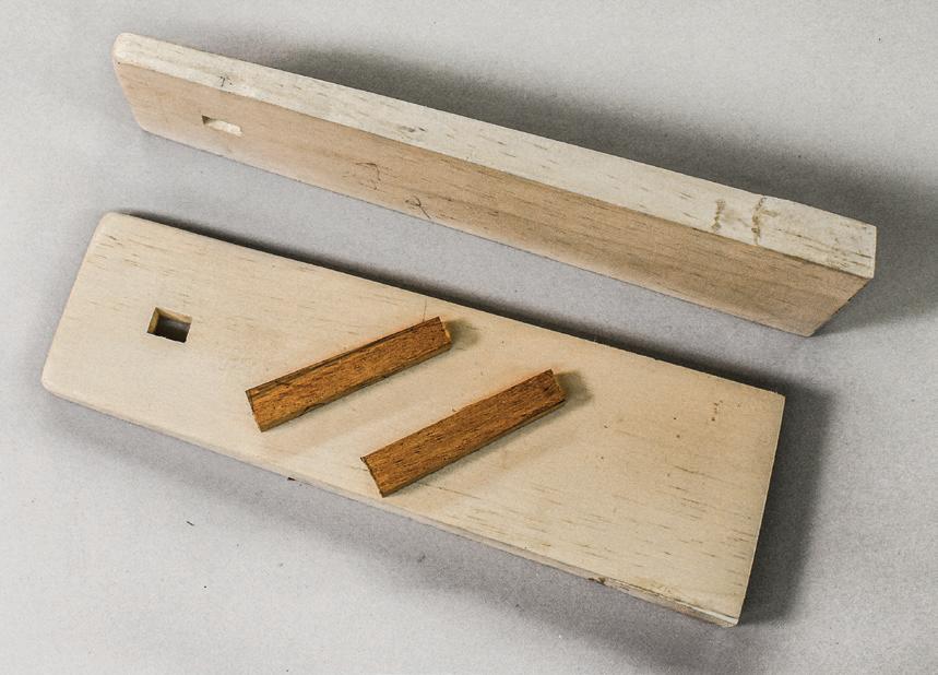

disassembled. But, in places, stump ends of these old nails still projected annoyingly from interior surfaces of the lifts and prevented them from faying against each other. I drove the nail remnants out with a nail punch. With the nails gone, the tenons drew the lifts together easily.
The model’s exterior surface had been exposed to daylight for so long that it was no longer possible to differentiate the pine and mahogany lifts; the dramatic design motif had become ineffectual. It was possible to strip off the old finish so the pine and mahogany could be distinguished but doing so would have sacrificed the original finish and the hand-lettered legend on the hull. Because the model had been disassembled and poorly treated for so long, the lifts’ edges and ends were dinged and chipped. This made the reassembled hull’s fairness difficult to read. By retouching the worn edges and ends with stain, the model’s appearance was reunified.
Another opportunity awaited that I would have been lax as a historian to have ignored. This was to record Inez’s hull shape for future reference by others. (Although a contemporary painting of Inez exists,34 I had no incentive to model her.)
Taking lines off half-models is laborious. I am awed by the efforts of historians, notably Howard Chapelle, who drew hundreds of vessel plans with what must have been speed and ease. It takes me a week to fair a set of lines, either on paper or on the computer. I didn’t want to take that time with Inez. Did I have an option? Yes: Simply trace and fair the information that the half-model presented.
The model’s bottom edge represented the hull’s keel rabbet. So, the assembled model was placed with that edge against the parallel rule on a traditional drawing board. The model’s profile was then traced in pencil on a sheet of drafting Mylar. The twenty-six station lines that were penciled on the half-model were then ticked off on the profile and erected with a triangle. Interestingly, the stations were neither
consistently spaced nor numbered. I maintained the irregular spacing and assigned numbers. Station No. 11, near the dead flat, was chosen as the dictator. I marked it with blue tape on each of the seven lifts. Each lift was placed on the Mylar, coordinated to Station 11, and traced in pencil. I now had six waterlines. The sheer line couldn’t be traced directly because the sheer was not flat. So, I transferred the sheer’s halfbreadths with dividers. Because a vessel was not actually being lofted from the model, the information density represented by all twenty-six stations was unnecessary. I only used the odd-numbered stations plus the last, No. 26. Also, at this point, I did not attempt to compensate for any damage along the lifts’ edges. I had now recorded almost all the information the halfmodel had to offer. Only the line of the cross seam at the stern was lacking.
The local copy shop scanned the large Mylar drawing in a single pass. The 300-dpi image was saved as a .jpeg file on a thumb drive, uploaded on my computer, and opened in Adobe Illustrator. The goal was to trace and fair the lines from the Mylar drawing.
The scan was rotated so the keel rabbet was horizontal. Then horizontal and vertical lines were drawn to create a grid that represented the heights of the waterlines (as shown by the thickness of the lifts, or roughly, but not precisely 13/16 inch), the irregular station locations, and the rabbet’s half-breadth, which was about 1/16 inch.
First, I traced the profile. Because of damage, there were many irregularities, especially along the bow profile. Using Illustrator’s pen tool, I drew lines that resmoothed damaged spots. Assuming all the damage created concave problems, I worked to the fair portions of existing curves. This was done for the profile and six waterlines. The half-breadth of the sheer was constructed from the tick marks that I picked off the half-model. An advantage of working on the computer is that lines can be rendered in different colors. This makes distinguishing congested lines relatively easy.
84
Station lines (arrows) marked on a lift’s centerline.
Locations for the mortises were scribed on both sides of every lift except the bottom of the bottom one.
The new pine tenons and mahogany wedges.
The new aft tenon before final fairing to the shape of the hull.
Drawing a gentle, sweeping curve, like a sheer line, is no easier on the computer than on the drawing board. On the latter, one must sight frequently along the length of a batten to assure it passes through offsets fairly. It is harder to do this on the computer. The line must still be foreshortened to check for fairness, but this can only be done (at least in Illustrator) by turning the monitor and sighting along the flat of the screen. There are no spline shadows to help reveal dips and humps in the curve. Practice is required.
Drawing a vessel’s lines reveals information that might not be recognized otherwise. On Inez, for instance, the heights of the bow and stern above the keel rabbet are identical. In profile, the sheer is symmetrical fore and aft. Its low point is at Station 13, just about exactly in the center of the ship’s length. Also, the hull’s side is flat (although it tumbles home) roughly from Stations 6 to 12 and from waterlines 2 to 6.
Normally, it’s possible to determine a model’s scale if the size of the vessel it represents is known. Inez registered 112 feet 5 inches in length and 26 feet 5 inches in beam.35 Such length on American merchant sailing vessels was measured along the deck, from the stern post to the deck’s fore-most contact with the stem. This distance is easily measured on a vessel but difficult to measure on a solid model because both defining locations are “inside” the volume of the model. So, to compensate for the difference, the length I worked with was 31 inches. (This reduction is based on the position of the sternpost’s rabbet relative to the stern.) It’s sensible to assume that the half-model was carved to a scale that was simple for shipwrights to work with. Tradition and the English measurement system suggest using 1:48 as a convenient scale. However, at 1:48, the model represents a vessel about 124 feet long on deck. This is too big. Adjusting the scale so the vessel fits the model makes the scale about 1:43, which doesn’t work conveniently with any easy English fraction.
It was not unusual for builders to alter the size of a vessel from that defined by its half-model. Naval archi-
tect and historian William A. Baker explained that “it was an easy matter to add a few frames amidships and breadths could be changed in proportion,” and Chapelle wrote that the practice of adding frames was “particularly common among New England builders.”36 But such changes, made in the mold loft, generally enlarged a vessel. A 112-foot vessel scaled from a model representing a 124-foot vessel was going the wrong way.
Another anomaly was that the length-to-beam ratios of the model and the vessel differed. The vessel was proportionally narrower than the model, thus supporting Baker’s and Chapelle’s idea that vessels were frequently lengthened during lofting or building. If this happened with Inez, perhaps her model’s scale could be calculated from its beam. Unfortunately, that didn’t work, either. In the end, I was unable to reckon the model’s scale with conviction.

The lines-taking exercise was designed to record information presented directly by the half-model of Inez. No attempt was made to construct from that information a full set of lines with a body plan, buttocks, and diagonals. However, from the data collected and preserved on the drawing, which can be found at the Custom House Maritime Museum, such work can be done in the future by anyone so inclined. ¯

85
Above. The assembled model.
Below. The profile, waterlines, and tenon locations taken from the model of Inez
Case Study 10
Yorkshire
1843: American Transatlantic Packet Modern Rigged, Full-Hull Model
YorkShire was a North Atlantic sailing packet, or a vessel that served a scheduled route to transport passengers and cargo, built in New York in 1843 by William H. Webb. William’s father, Isaac Webb, had started building ships in New York City early in the nineteenth century. By 1818, Isaac had his own shipyard, and he later took on a partner, John Allen. Born in 1816, young William became an apprentice in his father’s yard at fifteen. In 1840, at age forty-six, Isaac died suddenly. William was twenty-four but without hesitation took over the yard. He bought out Allen in 1843 to become the yard’s sole proprietor. In all, William created one hundred thirty-five vessels. He was known for innovative, successful ships and for his considerable business acumen. He built packets, ferries, side-paddle and screw steamers, and sailing vessels of all sorts including clippers. His career spanned the mid-century era when wooden ships increased enormously in size and when propulsion technology was making the complex transition from sail to steam. He closed his shipyard in 1869 because, following the American Civil War, there was a general depression in shipbuilding. Further, Webb, a dedicated builder of wooden ships, recognized the irrevocability of the trend favoring iron and steel. He was fifty-three. Perhaps Webb’s greatest legacy was the founding, in 1889, of what is now the Webb Institute in Glen Cove, Long Island, New York. America’s only school that specializes in naval architecture, the institute, through Webb’s philanthropy, remains active, influential, and tuition-free. Webb was a founding member, in 1893, of the prestigious Society of Naval Architects and Marine Engineers. He also assembled and published, in 1895, the massive, two-volume Plans of Wooden Vessels built by William H. Webb in the City of New York, 1840–1869. The work’s beautifully engraved plates are indispensable resources for today’s maritime historians and ship modelers. Webb died in 1899.37
Yorkshire was Webb’s thirteenth vessel and his third sailing packet. The forty-five packets he built embraced exactly a third of his total output of ships. Webb recorded that Yorkshire had a length on deck of 167 feet and a molded beam of 35 feet 4 inches. She measured 1,150 gross tons. (Marine historian Howard I. Chapelle indicated somewhat different dimensions.) The vessel had a cabin deck that extended from the mainmast aft to the taffrail; she carried forty-four cabin passengers. She was launched fully sparred, rigged, ballasted, and equipped with ground tackle and fresh water. She crossed royal yards on all three masts. Yorkshire was intended for the original Black Ball Line of packets that served between Liverpool and New York. Discussions of the North Atlantic packet trade are available in many sources. But it must be noted that Yorkshire was an impressive vessel. She “had the fastest general average of any of the one hundred and fifty ocean packets” of her type. In November 1846, she set a record for a west-bound Atlantic crossing of fifteen and a half days during a period when the average passage was about thirty days. Judging from her accomplishments, Webb’s note for Yorkshire in his Plans of Wooden Vessels was magnificently understated: she “proved a fast sailor and excellent sea boat and was a favorite in the trade.”
On 2 February 1862, Yorkshire sailed from New York for Liverpool and was never heard from again.38
Stylistically, Yorkshire’s lines plan is typical of many that appear in Plans of Wooden Vessels. Webb’s shipyard, like many, was devastated by fire, so numerous plans, models, and other records were lost. Fortunately, sail plans and tables of offsets seemed to survive. For Plans of Wooden Vessels, the offsets for vessels for which other sufficient information did not survive were rendered during the late 1880s as lines by Charles Philip Kunhardt, a skilled designer of smaller yachts.39 (Kunhardt was outspoken in the then-current vitriolic controversy of whether wide, shallow yachts were better or worse than deep, narrow ones; he used as a platform his position as yachting editor for the weekly sporting news-
86
paper Forest & Stream and wrote the book Small Yachts, Their Design and Construction, which first appeared in 1885.)
Peter Henrik Ness, who built this model of Yorkshire, was a native of Kristiansund, Norway. A mariner who sailed before the mast as a youth, Ness emigrated to the United States in 1912, at twenty-two. He petitioned for naturalization ten years later in 1922. He retired after twenty years at sea, took up ship modeling, and lived in East Boston, Massachusetts, until his death in 1956. His “private workshop” was on Leyden Street. He was productive, and his work became popular. His models may be found at the Science Museum, Boston, at Mystic Seaport Museum, and elsewhere.40
Ness’s powerful 1:48-scale model of Yorkshire (of which I regrettably do not have an overall image) had a solid wooden hull that had been planked over in what we today call the plank-on-block method. She was fully rigged. Running rigging for the square sails included braces, lifts, sheets, and clew lines, but there were no buntlines or leech lines.
Nearly all the model’s wooden components, including the spars, were made of varnished mahogany in a style that became Ness’s signature. Despite being mostly monochromatic and, thus, perhaps off-putting, the lack of a diverse palette was compensated by Ness’s attention to a range of entirely scratch-built gear, especially in the rig, that render his models compelling. His manner for choosing which details to stress likely stemmed from his time at sea. He knew instinctively what would be important to make models look like ships.
The model was in generally good condition because of Ness’s robust building practices and because it was encased. But the case was barely tall enough, and this was probably the reason for the model’s only problem: the main topgallant mast was broken. I suspect Yorkshire was being moved in or out of her case when the masthead ticked the case’s top frame. This specific damage is not uncommon and is frequently the result of two or more overzealous handlers who
are working too fast and not communicating as much as they should.
Working away from home in 1997, my tools and materials were limited to the few I carried in my briefcase.
The mast had broken at the mortise for the topgallant tye’s sheave for two reasons. First, the spar was weakened there by the mortise. Second, the stick for the mast had been poorly selected because its grain was not coaxial; it slashed across the spar. A straight-grained stick would have been more durable. Tellingly, the break was parallel to the slash and through the mortise. The good news was that the break was clean.
Access to the fracture was required. It is a tribute to Ness that he facilitated the repair to a significant degree. He had fashioned hardware and rigging so items could be disassembled, manipulated, and replaced relatively easily, like on a ship. This is a detailed review of the treatment.
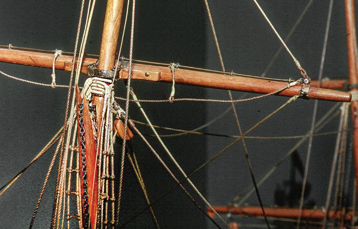
The portion of the topgallant mast above the break had to be raised quite a bit. But rigging above the break hindered upward movement. Lines had to be disengaged. I released the downward-pulling royal braces by unhooking their standing ends from their yardarm eyes. The royal yard’s gated parrel was opened by removing the locking pin. The main topgallant lifts were released by pulling the clevis pins from the yardarm shackles. The fore royal braces, which ran through blocks at the eyes of the main topgallant shrouds, were unhooked from their yardarm eyes. To provide plenty of slack in the main topgallant halyard system, I unhooked the whip tackle’s lower block from its ringbolt in the deck. The pair of topgallant backstays and the single royal backstay had to be released. The sensible scheme was to unhitch and overhaul the lanyards. However, Ness unfortunately tended to glue or varnish knot work
87
The break was through the mortise for the sheave for the chain topgallant yard tye. The slash break follows the spar’s grain. Notice the shackles and hooks at the royal yardarm bands and the served rigging eyes at the mast.

heavily. (On another of his models that I had repaired, he even varnished lines into blocks with working sheaves.) Varnished line doesn’t run through blocks and deadeyes, so it can’t be adjusted. Further, it becomes too brittle to untie without failure. These six backstay lanyards were saturated with glue where they were hitched to the shrouds, so they were sacrificed.
There still wasn’t enough upward movement above the break. It seemed like more standing rigging would have to be released. Then the solution came to me: Remove the topgallant mast’s fid at the trestletrees. Doing so permitted lowering the section of the mast below the break rather than requiring raising the section above.
Inspection of the fracture’s now-exposed surfaces revealed that mine was not the first attempt to repair it. There was already hard, crystalized glue in the break. The earlier repair was poor — there had been inadequate contact between the two pieces of the wooden spar. Glue had found its way into the mortise for the chain tye and had clogged its links and the brass sheave. Using a No. 11 blade and dental picks, I chipped away the old, brittle glue.
I considered two scenarios for the gluing process. The first was to glue the mast with the lower portion outside its step in the trestletrees and the cap. This would be most convenient, but the upper rigging would still be too taught to permit sufficient upward movement to get the mast through the cap. The second approach was to glue the mast with lower portion stepped. This is what I did.
It was critical to rehearse the proper mating of the spar’s two fragments. So far, I had avoided working the two surfaces against each other because wood fibers
in a break will only reassemble perfectly once. Every time a test fit is made, the fiber arrangement is compromised. Moves must be practiced so they can be duplicated once glue enters the scene and makes surfaces slippery and harder to see.
During rehearsal, I noticed that, when the mast was in its final position, the forward-pulling main topgallant and royal stays were extremely taut. I didn’t want their tension to stress unnecessarily the new glue joint. To counter the stays’ forward pull, I rove off and took tension on the new topgallant backstay lanyards. I didn’t want any glue in the sheave mortise, so many lines, especially the tye chain, were held out of the way with retractable-hook test clips.
At last, I coated the joint with PVA glue, then mated and clamped the two pieces of the mast. To clamp the two pieces together while the glue was setting, I used a small binder clip. Initially chosen simply because it was at hand, the clip worked excellently because it provided three-way support, the best for clamping a round object. Next, a 1/16-inch-diameter hole was drilled across the glued joint, and a length of brass rod was inserted in it. The rod’s alignment was about perpendicular to the break’s mating surfaces rather than horizontal. The idea was to reduce sheer stress on the glue line from the downward pull of the tight rigging. The rod was secured in place with a spot of cyanoacrylate glue. After excess glue was carved away, the repair was in-painted with artists’ acrylics.
The mast’s overall height had been reduced slightly, perhaps 1/32 to 3/64 inch, when the old glue was removed from the fracture’s faying surfaces, so the topgallant shroud lanyards were now slightly slack. They needed to be overhauled. But, having been varnished, they did not run in their deadeyes. These lanyards were also replaced.
With all the standing rigging secured anew, it was time to address the running rigging. This was done in the following order: I adjusted the length of the chain topgallant tye, which now ran smoothly over its sheave,
88
After disassembly, the topgallant mast break was open for inspection. Part of the tye mortise is visible at the upper end of the break. The brass tye sheave (arrow) is in the upper portion of the mast. The break’s surface was caked with old glue from a previous repair. Notice the brass sheaves in the blocks.
A binder clip provides three-way support on a round spar.
and rehooked the halyard fall to its deck ringbolt. The royal yard parrel gate was secured around the mast with its pin. I rehooked the main topgallant sheets and brace pendants and main royal braces to their respective yardarm eyes. The upper block for the main topgallant staysail halyard, which I didn’t want to replace, required a new strop, but the eye at the standing end of the halyard was stuck in the strop at the block’s arse. I carved away the old strop carefully to avoid cutting the halyard eye. I made a new strop, seized it in place, and hitched it to the stay as Ness had done elsewhere. Finally, both fore royal braces were rehooked to their yardarms.
To leave room for fine tuning, hooks were left open and new lanyards were left untrimmed until everything

was assembled and happy. All six new backstay lanyards were given a final adjustment and were hitched around their stays in Ness’s fashion: The lanyard passed through the gap between the deadeye and the stay, one hitch was made around the doubled stay, then three turns were made around the stay and a final hitch was made. This arrangement let the hitches slip because the turns did not seat snugly. Ness eliminated slippage with varnish or glue. In my case, the upper hitch seemed to want to come undone and to beg for glue; but I resisted the temptation.
New line was stained to match the original rigging. Hooks were closed and rigging ends were snipped close. Yorkshire needed no other work. ¯

Left. Using a hand-held pinvise (arrow) to drill the hole for the pin that will reduce sheer stress on the glue line. Retractable-hook test clips hold rigging out of the way.
Above. Downward force of the part of the mast above the repair is checked by the pin that is perpendicular to the break (A). With the pin horizontal (B), the upper part of the mast can work off the pin if the glue in the repair fails.
Right. The completed repair to the main topgallant mast. The glue line is faintly visible under in-painting.

89
A B
Case Study 11
Unidentified about 1865: British Merchant Steamship
Contemporary Rigged, Full-Hull, Builder's Model
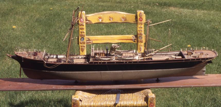
ome models are fascinating beyond what you know about them. Neither particularly large nor complex, this example presented a level of character that was visible even through considerable damage. At the now-distant 1979 moment when I encountered it, I hadn’t yet refined an understanding of the defining qualities of formal builders’ models — the genre of slick and visually powerful display models developed in nineteenth-century Britain concurrently with the advent of ever-larger and more sophisticated steamships of all stripes. At a length of about 48 inches, this example was part of a private collection of models that ranged up to about 165 inches in length and, among them, seemed all but insignificant. But it was a harbinger. It displayed many builders’ model characteristics that were to mature over the following few decades. For instance, its solid (and surprisingly heavy) wooden hull was completely smooth outboard with no representation of the vessel’s skin texture at all. Hatch cover and deck details were ruled crisply in ink on bright wood rather than built. Each boat was carved and hollowed from a single wooden block; interior detail was a wooden panel insert, and floorboards were paper strips glued inside the bottoms. Standing rigging was fashioned from twisted wire rope. But there were differences, too. The scale seemed to be 1:64 (or perhaps even 1:96), whereas later builders’ models were almost universally larger at 1:48. On deck, cargo winches and their gears were wooden and painted, in contrast to later models on which the assemblies were of machined and cast metal parts that were frequently left bright or plated. The funnel was bright brass, where later funnels were painted to display shipping company liveries. The ship’s wheel, lifeline stanchions, belaying pins, deadeyes, and blocks were well-crafted ivory, a substance rarely found on later builders’ models; their whiteness popped visually alow and aloft.
The vessel represented by the model was long, fullended, and capacious; there was no parallel mid-body.
It resembled more the sailing merchant ships in the final fling of the sail era than it did the steamers that would put them out of business. But this was a single-screw steamer with a decidedly auxiliary sailing rig. Forward, an elegant extended head with gilt décor concealed a conservative but true clipper bow. Abaft the raised forecastle was a well deck, then the rail rose again and continued unbroken to the counter stern. The principal deckhouse was amidships, but it was short, rising only as high as the rail. The house was surmounted by a small structure that was probably a pilothouse (though it lacked any access or fenestration) with a bridge winged to the sides, a single tall funnel, two boats (one with a saucy elliptical transom) on each side, and an engine room skylight with portholes. A steering wheel and elevated grating stood right aft on the poop; their elegance suggested this was the principal steering station, but it was almost certainly secondary to the pilothouse.41 She sported a pole bowsprit and was masted as a topsail schooner, with fore-and-aft sails on each of two masts and square sails on the foremast.
It wasn’t as easy, in 1979, to identify vessels as it is now. Unless you could afford traveling to and spending plenty of time — perhaps many days — at maritime museums, libraries, or other depositories of large image collections, you were limited to books. While books helped, they necessarily offered only relatively small samplings of individual vessels and vessel types. Possibly because the collection to which this model belonged represented mostly British vessels, I assumed it was also British. From one book, I quickly learned that the actual vessel was likely a small, early screw-propelled passenger-carrying cargo vessel.42 After looking through several books, it became clear that the ship didn’t date any later than the 1880s, and that was the closest my research could resolve things in the early 1980s.
But now we have the Internet. The romance of travel, the prospect of encountering interesting people and research traditions in far-away archives, and the thrill of discovering and handling actual artifacts may
90
The model as first seen.
S
be gone, but the economy and comfort of working at home are hard to resist. It’s easy to place a picture of a model in a window in the corner of your computer screen and quickly compare it with images on the Internet. The results of Internet research can be amazing. Many Web sites include thousands of photos of vessels of all sorts. As examples, in 2016, clydesite.co.uk listed twenty thousand vessels built on Scotland’s River Clyde; navsource.org listed seven thousand American naval vessels; norwayheritage.com listed fifteen hundred transatlantic immigrant ships that stopped in Norway; photoship.co.uk included nearly a quarter million images of vessels from everywhere (but it is now defunct); and wrecksite.eu tracked about one hundred sixty-five thousand vessels by their losses. Some of these archives can be sorted — by date, use, propulsion, shipping line, and so forth — to hasten searches.
Clicking and scrolling through virtual images, I kept several of the model’s markers in mind: the clipper bow with its pole bowsprit, the rail with the drop for the well deck, the single funnel, the lack of paddle boxes, the rail-high deckhouse, and the topsail schooner rig. By sorting an archive chronologically, it was easy to learn when features evolved and when they became passé. For instance, once I saw that clipper bows fell out of general favor on smaller passenger-cargo vessels in the mid-1870s, I could end searches for the prototype of this model then. There were few screw-propelled or clipper-bowed steamers with two-masted rigs; they were employed close to home, seldom traveling beyond the Baltic or the Mediterranean. Many examples matched the model in a couple of ways, but none in all.
Despite the Internet’s efficacy, though, it’s healthy to prepare for disappointment. Although hundreds of vessels may be listed, there may be images for relatively few, especially if the target date was before the advent of photography’s ubiquity. This swept in with the debut of dry-plate photography in the late 1870s. The new process allowed glass plates to be prepared with emulsion far in advance of the moment of exposure and processed
long after. The emulsion was many times more sensitive than those used with previous wet collodion techniques, so exposure times became short enough that cameras could be hand-held. Photography exploded.43
Incidentally, this improvement provides a tool useful for dating photographic maritime images. If water — say around anchored or docked vessels — appears pale and milky, the image was likely captured in the 1870s or earlier with a long exposure that couldn’t stop wave action. If water details are crisp, the exposure was short, and the image was likely made in the 1880s or more recently.
If a perfect match isn’t available, it’s generally possible to estimate a vessel’s place, time, and trade. For this model, that was the best I could do. Information from various sources helped me to determine, with some certainty, that the model represented a merchantman from about 1865. This was earlier than I’d originally thought, but that’s why the search was made. She principally carried cargo, but a few passengers could be accommodated, probably under the poop, as in sailing ship days. She was about 250 to 275 feet long and measured about 1,500 gross tons. The vessel was small and probably not intended for transatlantic routes, although she may have worked out to the East. Overall, the model displayed an elegance that may have eclipsed that of the vessel it portrayed.
The Work
The model was in shambles. The rudder and propeller were gone. The bowsprit was disengaged. Both topmasts were shattered. Lifeline stanchions were out of their sockets, and some were unfortunately broken. A section of the helmsman’s grating was missing, but, thankfully, the ivory wheel was in good shape. The four boats were a mess, and, somehow, the funnel had been squashed without destroying all the rigging between the two masts. This job was done on site in 1980. My workplace was an awkward round table on a residence’s glassed-in
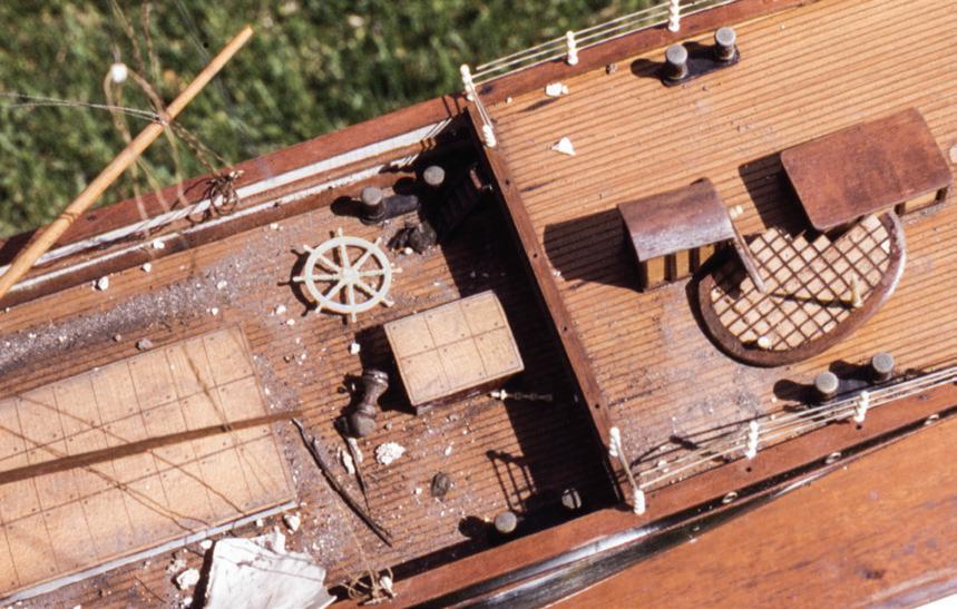
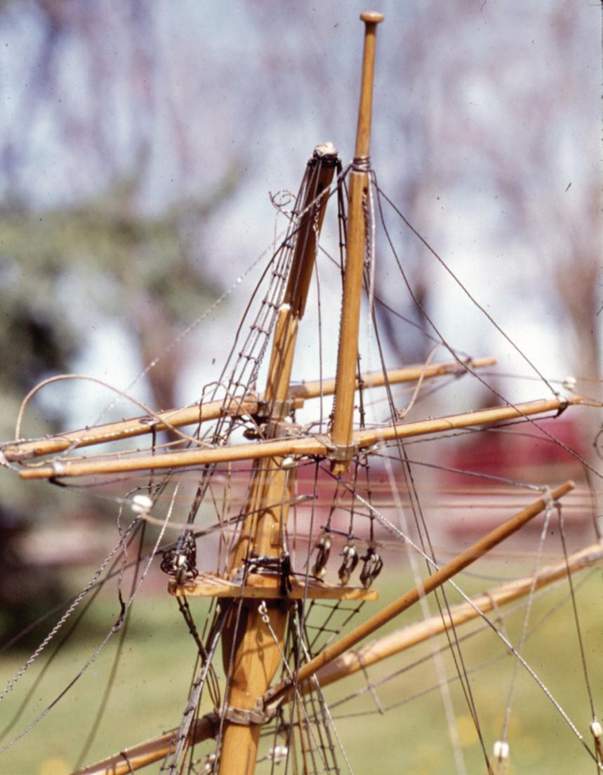
91
Dirt and debris near the stern. Amazingly, the ivory wheel was intact. The checker-board item is the helmsman's platform.
Breaks in components of the boxwood fore topmast.
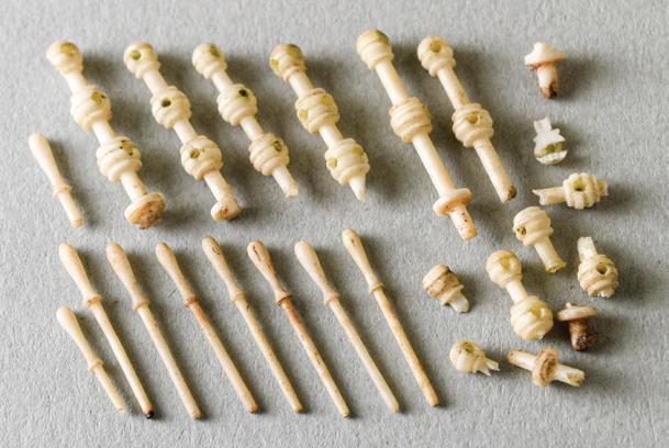
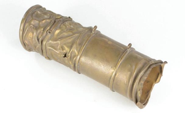

porch. I had only the tools and other resources I could carry with me and five days’ time.
Lots of soot, dust, and debris had to be removed. Almost everything inboard of the rails was finished in natural woods. A weak solution of linseed oil and turpentine in water applied sparingly with a pad of 0000 steel wool cut the grime. Then the parts were dried, waxed, and polished. The result was a hard finish that was easily maintained. This was early in my career; I later avoided these techniques, but they held up for the twenty-three years that I ministered to this uncased model.
Most of the repairs were straightforward. A new stern frame-rudder unit was made of basswood, installed like a graving piece, and in-painted. A propeller that fit was cannibalized from another model that had been destroyed beyond salvation.
The ivory lifeline stanchions posed a problem. While most fragments of the broken ones were with the model, I didn’t feel they could be repaired satisfactorily; they’d be too fragile. Attempts were made, but, because the model was displayed uncased in a busy passageway, the brittle stanchions continued succumbing to rough handling and looking poorly. With strength and longevity in mind, I began a program of replacing broken ivory stanchions — and belaying pins — with more durable brass ones machined by the late Chris Morrison, a ship modeling colleague from Cambridge, Massachusetts. The new brass was in-painted to resemble ivory.
The funnel was the toughest nut to crack. Being brass, it was soft, but the crushing, which had reduced it to about half its normal height, had work-hardened it in just the spots where it most needed attention. I called on Tom Odell of Chatham, Massachusetts, a creator of sculpture and jewelry in all sorts of metals and an all-around clever fellow. We didn’t think we could save the fitting, but we needed to know more about it. Odell started working the wrinkles out of the brass by pulling on the funnel’s ends with jeweler’s pliers, a
little here, a little there. He considered annealing the brass to render it more malleable. However, he realized that the applied details — reinforcing rings and eyes for the guys and steam escape pipe — prevented access to enough surface of the basic tube to smooth it to presentability. He decided to de-accordion the funnel just enough to determine its original size and the detail locations. He stopped when the brass began to break and tear because of metal fatigue. He then worked up a new funnel from a rectangle of 0.020-inch-thick brass sheet, rolling it into a tube and soldering the long seam, as the original had been. The rings and eyes were then easily made and applied.44
All the spars were boxwood. To make them accessible for repair, much of the rigging was removed and cataloged. Fortunately, breaks to the masts were long, ridged splits so they could be epoxied and clamped with perfect register and without slippage. Some unstressed spars were repaired with nonferrous coaxial pins. Most wire-rigging components — shrouds, stays, and pendants — survived and were reused; the headstays had to be replaced. The deadeye lanyards and most of the fiber running rigging were replaced so the rig could be tensioned properly.
It was disappointing that the model’s identity was never nailed down. But I felt like I had saved the model from the brink of fate: the bone yard. ¯

92
Above. The foremast has been repaired. Blocks and deadeyes are ivory; standing rigging is wire rope. Far right. The finished model.
Some of the original ivory belaying pins and fragments of lifeline stanchions.
The brass funnel after Tom Odell tried to straighten it.
ecause of its historical juxtaposition at the cusps of wood and metal construction and of steam and sail propulsion, and because both sides needed to amass weaponry for a war that had seen little arms build-up and that was thought would be short-lived, the American Civil War spawned a vast array of bizarre naval vessels. The odd-ball Monitor and the cobbled-up Virginia only foretold the future. Dozens of vessels built by the Confederate and Union navies struggled to fit the needs of specific combat environments. On the broader front, though, the Union feared foreign powers might enter the war. To help deter their involvement, the Union Navy sought a speedy, powerful, and longrange cruiser.45 The result was Dunderberg.
Dunderberg (a mountain on the Hudson River) looked like nothing less than the first warship with stealth capabilities. But she was actually an armed and armored, steam-powered propeller ram with an auxiliary topsail schooner rig. She was the creation of William H. Webb, the innovative New York City ship designer and builder. Although Webb was known for his sailing packets (as we saw with the study of Yorkshire, Case Study 10) and clippers, some believe Dunderberg, built near the end of his active career in the shipyard, “may have been his most significant contribution to American shipbuilding.”46
Dunderberg was started in 1862. After modifications during building that made her longer and narrower than originally intended, she was 377 feet 4 inches long and 72 feet 10 inches in breadth. Other modifications included the elimination of a pair of turrets atop the casemate (an armored gun housing) in favor of a longer casemate housing more carriage guns and the addition of the auxiliary sailing rig. She displaced about 7,000 tons, ready for sea. By comparison, the USS Kearsarge, which had a decidedly more significant role in the war, was about 201 feet long, 34 feet in breadth, and displaced 1,550 tons.47
Upon her launch in 1865, The New York Times reported that Dunderberg was a “formidable-look-
ing craft, of extraordinary dimensions and strange model.” In his 1882 official Report on the Ship-Building Industry of the United States, Henry Hall wrote that Dunderberg was “considered in her day the most formidable fighting ship in the world.” Modern historian Donald Canney wrote that she became in one moment “the most powerful [iron-clad] in terms of firepower in the U.S. Navy.” And maritime historian Llewellyn Howland III said she, like Isambard Kingdom Brunel’s Great Eastern of 1858, was “out of scale with the technology of her time.”48
Case Study 12
Dunderberg
1865: American Ironclad Steam-Powered Warship
Contemporary Rigged, Full-Hull, Builder's Model
Unfortunately for Webb (but fortunately for everyone else) the war ended before the mighty ship was completed in 1866. On trials in 1866 and 1867, she did not make her contract speed of 15 knots. Amid controversy, she was rejected by the Navy and was returned to Webb in exchange for advances he’d already been paid. With lots of money at stake, Webb had needed another buyer. Refusing offers from South American countries for political reasons, he succeeded with the French, who wanted to do some saber-rattling of their own and who renamed the vessel Rochambeau. They managed to get the 15 knots out of her, but reported that she was wet, had a quick roll, and was unsteerable under sail alone. They modified her inboard and out, shortened her overhanging stern, and re-armed her with French guns. She saw brief duty in 1868 before being put in reserve. In 1870, she was reactivated for Baltic Sea duty at the beginning of the Franco-Prussian War, but evidently wasn’t terribly useful and was again laid up. She was scrapped in 1874.49

93
The refurbished model of Dunderberg
B
Three Models
Webb reportedly sent a model to the Navy Department with his proposal for the ship in 1862. Dana Wegner told me that there has never been a model of Dunderberg in the Navy’s collection. The Smithsonian Institution does hold a half-model of her. The model “was donated by William H. Webb…in 1933.” It was built in the period from 1862 to 1865, and…shows the casemate, the funnel, stump masts, cowl vents, and the armored command station. It was a whopping 123 inches long and 11 inches in half-beam.50 If Webb sent this model as the proposal for Dunderberg, the model was as monumental as his scheme for the vessel. The original proposed length for the ship was 368 feet, so the model was built to the scale of 1:36, which was not common but somewhat unwieldy in the English system. It seems likely that Webb reclaimed the model when he settled accounts with the Navy in 1867, then the model found its way back to Washington in 1933.
In the Webb Institute’s Livingston Library resides one of two contemporary full-hull, rigged models of Dunderberg known to exist. The other is in the Musée de la Marine, in Paris, France.51 In photographs, these two early models appear to be identical. They show the vessel in her as-launched configuration with no turrets, the longer casemate, and the sailing rig.
I wondered if the two models were built before the ship and if they were used by Webb as sales tools. Perhaps there was a way to find out. When she was launched, Dunderberg was 377 feet 4 inches long. However, her proposed length was only 368 feet.52 By my measure, the model’s hull was 68⅞ inches long. At 1:64, a model of the proposed 368-foot vessel should be exactly 69 inches long. The ⅛-inch difference between the lengths of the model as it was and as it should have been to represent the 368-foot proposed length amounts to about 0.2 percent, a tiny error. A model of the completed 377-foot 4-inch vessel at the same scale should be 70¾ inches long, a difference of 2.6 percent.
Thus, I safely assume that the pair of models was built to the proposed specification, before the vessel was complete. But, if this was so, why did they show the asbuilt casemate, armament, and rig? Perhaps the models had been started before the vessel was altered, and then Webb had the models corrected to the ship’s final arrangement. If this was so, then it seemed likely that the full-hull models — the one in Glen Cove and the one in Paris — were used to promote the ship. It seems doubtful that Webb would have invested in the models after the vessel was gone.
The Institute’s Model
I’d read about Dunderberg many years before receiving a call from Webb Institute, so her oddity did not startle me. But I was surprised to learn that a model dating from Webb’s time with the ship was still around. I was told that the model had a few rigging problems, that the wooden deck was split, and that the model was made of iron. Made of iron?! This was a contemporary ironclad model of an ironclad vessel? I responded, “Please send photos right away!” I took the job. The model was transported from New York to my studio in a private car in 2008.
From the level of the main deck downward, the model had a solid wooden hull. At the bow was a huge,
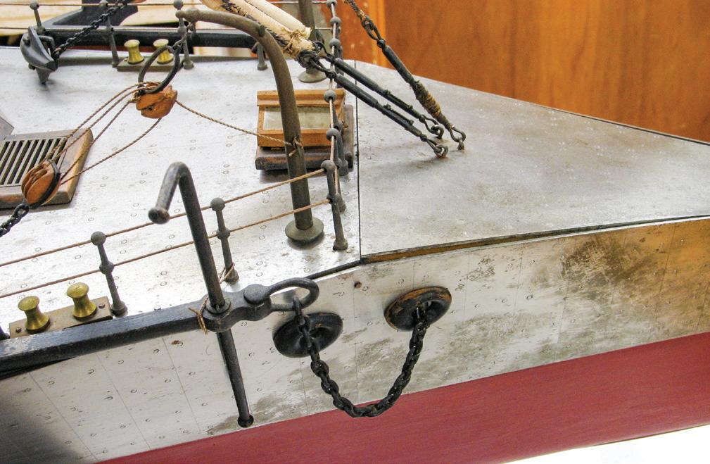
94
lethal-looking ram. At the stern, the hull was broad, flat, and shallow with faired side curtains that hung below the waterline to protect the single, four-bladed propeller and both rudders. Yes, she had two. The primary one hung normally on a rudder post abaft the propeller. The “reserve rudder” was built into “the deadwood ahead of the propeller.” It was, in Webb’s words, an “equipoise rudder” fitted in a “new and novel manner.” (Today we call this a “balanced trim tab.”) Above the main deck, a slope-sided casemate covered about 60 percent of the hull’s length. The casemate’s sides and ends were pierced with twenty-two gunports. On the model, there was a gun in each port, but the ship evidently never carried this many.53
The ram, the hull above the waterline, the main deck, and the casemate were, indeed, sheathed with metal plates. They were stamped with small circles to represent hundreds of bolts that held the original plates to their wooden substrate. But the plates were held to the model with relatively few, small fasteners that appeared to be hand-made cut nails. Many plates were loose, but none had come completely off. My guess is that the wooden hull under the plates had shrunk from dehydration, and this caused the nails to work free. A magnet told me the sheathing was iron-bearing, but I never determined if it was pure iron or an alloy. It had no finish. It was dark and tarnished, especially at the

ends where generations of handlers had picked up the hull with oily and acidic bare hands.
The casemate’s top was covered with a wooden deck. It was a single panel of wood with scribed planking. It also bore no finish, was stained here and there, and had a substantial twisted split toward each end. The funnel and engine room ventilation gratings were in the center of the deck, and the masts were forward and aft. The masting and standing rigging were intact and in fairly good shape. However, the running rigging, which was silk, was tired and ready to crumble. I treated it with great care. Not having made the leap entirely away from traditions of the sailing Navy, the upper deck’s sides were bracketed by hammocks stored in troughs.
Removing the Deck
The deck was a pale softwood. The split at one end was twisted and opened enough that I could measure the panel’s thickness at 5/32 inch. Initially, I thought it was beyond hope. To replace the deck, a new panel was prepared by resawing, edge-gluing, and planing to thickness a suitable straight-grained basswood plank.
My notes say that I “removed the old deck,” but it wasn’t that simple. Fasteners for the skylights, pilothouse, companionway, cowl vents, and other features were extracted easily. The funnel was secured by a large
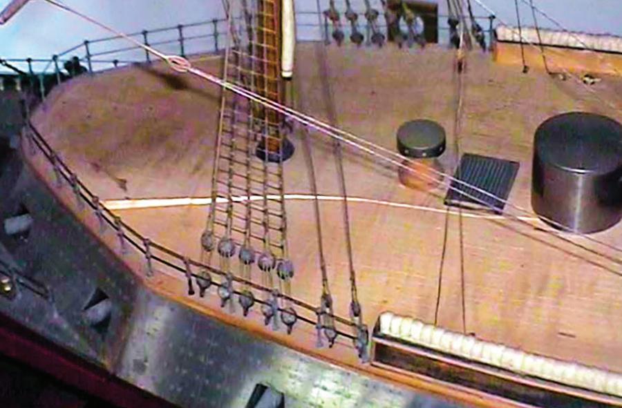

A carved cleat, a block with a served ropestropped block, and a thimble that has lost its line are near the deck edge, which has warped upward inside the margin. Behind is one of the major deck splits. Compare the block with those in image C on page 10.
Far left. Plates lifting from the wooden substrate at the complex intersection of the topsides, the upper surface of the ram, and the foredeck. Many false fasteners are visible, but only one real nail is evident as a dark spot between the hawse lips.
Center. There was severe tarnishing on the model’s metallic bow from being handled without gloves.
Left. The split in the forward portion of the wooden upper deck. There was a similar split in the other end. The cylindrical fixture to the right is the pilot house. (Photograph by the Webb Institute)
95
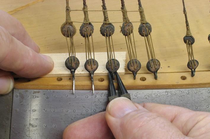


flathead wood screw in its center, so that was turned out. The lifeline stanchions were carefully pulled from the margin around the deck. All these things were installed on a memory board for the deck. Each mast was rigged independently of the other. No lines connected them. It would have been easy to sacrifice the deadeye lanyards for the standing rigging, but I wanted to preserve as much original rigging as possible. So, I gently pulled the fittings for the lower deadeyes out of the deck margins. I released the few running rigging lines that were belayed to beautifully sculpted wooden cleats around the deck and opened the links for the stays’ dummy turnbuckles. With this done, the masts lifted nicely out of the model as complete units with all their rigging intact. I “stepped” them in small stands made for the purpose and put them aside.
A wooden margin was pieced around the casemate’s top edge. The deck fit inside the margin and was flush with its top. The seam between the deck and the margin was exposed everywhere except under the hammock troughs. The hammocks kept me from seeing how the troughs were attached. The troughs wiggled, so it was clear they could be removed. They resisted being pried up, so I guessed they were screwed down. I could sense where the screws were. I lowered my view to the height of the seam and shone a flashlight through the narrow gap. Sure enough, I could see a screw. I used an auto-
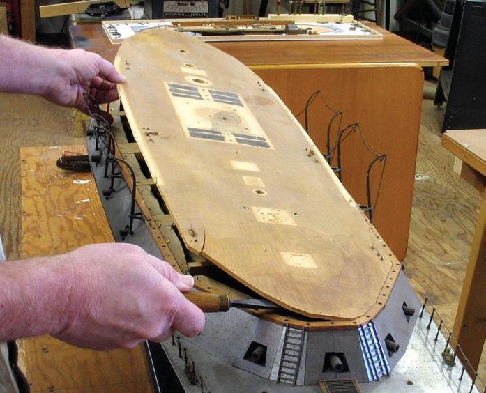
motive feeler gauge to show me its location, then removed the hammocks directly above. Bingo, there was the head of a wood screw. After removing it and several others, the troughs were free. Then the deck-to-margin seam was completely exposed.
Using a ⅝-inch flat chisel as a pry, I gently worked around the deck, lifting it away from the seam along the margins. Many small nails held the deck to the substrate. Under the deck were heavy beams that were useful for continuing the prying job. Soon, the deck was liberated.
In addition to the large split at each end, the deck panel had split at the location of each hammock trough screw. These small splits were old and were the result of the modelwright not drilling pilot holes. The splits had been completely covered by the troughs and were easy to squeeze shut with finger pressure.
I began thinking the original deck might be saved. To experiment, I worked PVA glue into a couple of the trough screw splits and clamped them closed. That worked. To flatten the deck — that is, to correct the twist and long split at each end — I considered installing shims on the underside, across the splits, to tie the two sides together. The shims would be placed to lie between the beams and the casemate sides. While puttering at this, I realized that the big splits would also close with effort, but not too much effort. I decided

96
Upper deck fittings and other gear on a memory board. The perimeter rim keeps unattached parts from falling off. The dirty and split upper deck lies in the background.
Removing the deck from the model. It was only attached around the periphery, not to the beams.
Removal of three hammocks, each of which was a short, bent length of fabric-covered wire, revealed a screw holding the hammock trough to the deck. The foreground fittings are davits.
Lifting deadeyes from the deck margin with roundnose pliers. The plier tips work against a block (arrow) that protects the soft deck.
After removing the mainmast from the model, it was placed in a temporary stand.
to keep the deck. To glue the splits closed accurately, I lay the deck panel on a piece of heavy plywood that extended over the edge of the worktable. After several gluing and clamping operations, the splits were closed, the deck was flattened, and the shims were in place. The shims added enormously to the gluing surfaces to help keep the big splits closed.
The original modelwright had never applied a finish to the deck. At some point, however, someone had tried to clean or treat a portion of it with some sort of cleaner or finish. It changed the color considerably. It did not look healthy and required correction. Taking a deep breath, I tried rubbing an inconspicuous corner of the deck with 220-grit sandpaper. Amazingly, this easily removed the discolorations and blemishes. Unfortunately, though, in a couple of places the scribing for the planking was compromised. To fix the scribing, I used the rounded back edge of a graver, dragged along a steel rule. This gave excellent control for matching the depth of the original scribing. After rubbing with 0000 steel wool, the deck was clean and lustrous, but still without finish.
The Interior, Briefly
Because nothing was visible through the casemate’s gunports, I was keen to see what was inside. With
the deck off, all was revealed. It was plain to see: No attempt whatsoever had been made to render the interior of the model like the interior of the ship. Up to the main deck level, the hull was solid wood. An obvious (and slightly open) centerline seam indicated the hull was constructed with port and starboard halves. The casemate sides were stout blocks of wood attached to the hull. Heavy, out-of-scale deck beams were mortised into and screwed to the casemate blocks. The only other things inside the casemate were the guns. Outboard, the guns looked complete, but inboard, they were simply unshaped extensions of the muzzles. They were stub cannon. The inner ends were strapped to wooden blocks, and the straps were screwed down. There was nothing else except a lot of grime and the detritus of the original model building — some wood shavings and the like. I photographed the interior for the record and then vacuumed it clean.
Plating
The metal plating presented two distinct challenges. The first was to clean the metal. The second was to reattach the loose plates.
It was important to avoid scratching the surface of the plates. I tried several cleansers, but all were in-


The interior of the casemate at the stern after cleaning. Notice how the blocks supporting the dummy cannon are chopped to fit in the space. What would it have been like to fight these guns? Blue tape protected the wooden deck margin while the casemate siding plating was being polished.

Far left. Gluing the major split in the forward part of the upper deck (A). A piece of ½-inch plywood (B) works as a surface plate to insure the deck is flat. Aluminum foil, which isn’t visible, prevents gluing the deck to the plywood. Pressure from the four wooden furniture clamps is distributed with athwartship cauls. The long orange-ended bar clamp (C) presses smaller plywood panels (D) against the edges of the deck to close the split. Squeeze clamps hold the smaller plywood panels to the base piece. And the long C-clamp (E) presses a block directly over the split. The deck is upside down to prevent marring with the clamps and to assure it is flat agains the plywood.
Left. The port side (top, in the image) of the after deck has been polished, but the starboard side (below) has not. The bright rectangle in the starboard side is the footprint of half of a skylight.
97
A B D E C

effective. Then I tried a standard metal polish called Nevr-Dull. It is billed as being mineral-spirits-based and uses calcium carbonate as an abrasive. It is stable and benign.54 The product is cotton-like wadding saturated with polish. Tear off a little of the wadding, scrub the metal until the metal is clean and the wadding is dirty, toss the wadding, start over. The process was messy. To protect the unfinished wooden margin around the top of the casemate, I masked it off with blue painter’s tape. For thoroughness, I removed the boat davits and their brackets. These I polished separately, along with the anchor davits, cowl vents, ladders, bitts, the funnel and its foundation, and other miscellaneous metal fittings. The process was slow and required gallons of elbow grease. But the tarnishing at the bow and stern and most other discoloration were removed. There were no new scratch marks. The plates became clean, bright, and uniform in appearance.
Most of the plates remained secure on the model. But several were loose or falling off. All of these had to be replaced somehow. Each plate was held by about eight to ten nails. Luckily, all but about ten of the original nails survived. Where necessary, I used new steel nails with their heads hammered square-ish to fit the holes and to imitate cut nails.
Removal of a couple of the plates revealed that, in addition to having been nailed on, they had been glued on. I found swirls of old, dried glue on the backs of the plates and on the hull and casemate. It was certainly some form of animal glue — hide glue was most likely. I spoke with a furniture repair specialist (he was not a conservator) who reported that hide glue would, in fact, hold steel to wood. I wasn’t so sure. It had failed on Dunderberg. To ensure as much contact as possible between the plates and the substrate, I scraped away all the old glue. Then I decided on a modern solution and used epoxy. I labored to replace the plates so the seams between them were tight and fair. This was complicated by the fact that the hull had shrunk somewhat — that’s why the plates were loose
in the first place. But I did not want to modify the edges of any plates for a better fit. This required a bit of scripting so things would proceed smoothly when I was actually fastening them. With the plates cleaned and replaced, I heaved a sigh of relief.
Reassembly
The last big job was to reinstall the deck panel on the casemate. But first, there was some foundation work to do. A large hole had been drilled in the deck beam that spanned the casemate under the pilothouse. The hole weakened the beam to the point that it wasn’t doing any work. I installed a basswood block on each side of the hole to support the center of the beam. The combination bulkhead and beam across the aft end of the casemate had not been fastened and was loose. I glued it in position. The tops of some of the beams were proud of the casemate blocks. I shaved down these beams so they were flush with the blocks. Although it had not been originally, I decided to glue the deck down. This was because I wasn’t confident that the fasteners that secured the deck would not split it again (it was now even drier and more fragile).
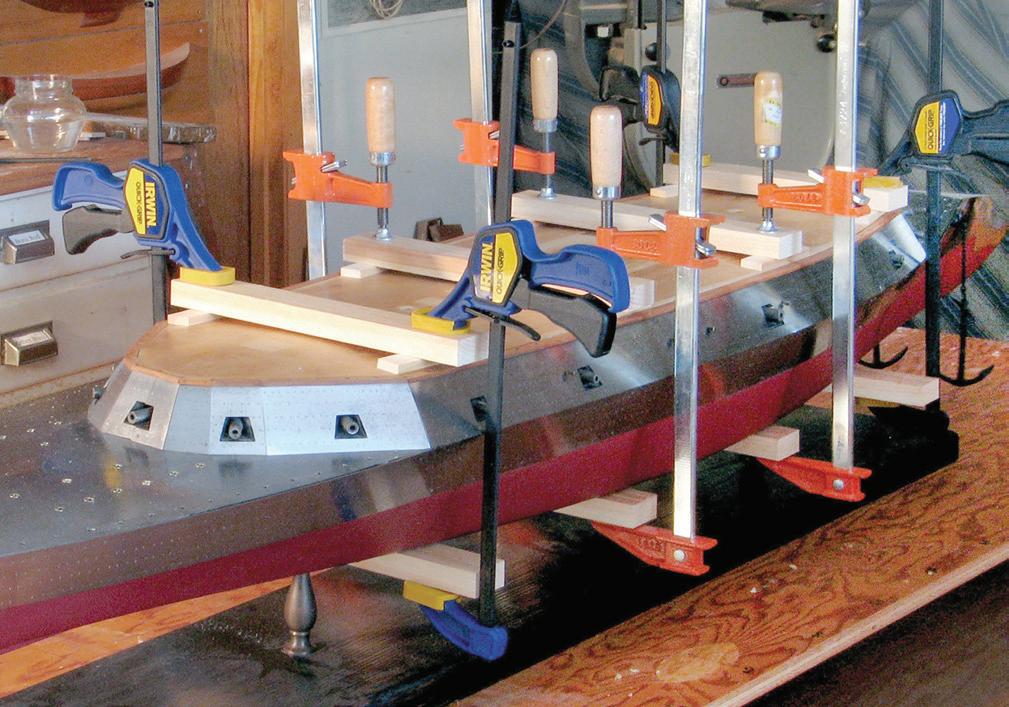
98
Armor plating at the stern extended below the waterline to protect the rudders and propeller. A corner of the opening for the “equipoise rudder,” which is above the propeller shaft in the deadwood, can just be seen (arrow). The nailing pattern for holding plates to the wooden substrate is visible where a plate has been removed at the stern.
The arrangement of clamps and cauls for gluing the new deck to the top of the casemate.
The bottom surface of the old deck was so roughly finished that it would not allow great contact with the substrate. So, I smoothed the bottom with 120-grit sandpaper.
After gluing the large splits in the deck, it was somewhat narrower than it had been. This meant the deck would not completely fill the area between the margins, port and starboard. There would be a gap. Because the masts and other fittings had to be on the centerline, the gap would have to be even on both sides. I didn’t like the idea of the gap and considered filling it with thin basswood splines. But this would look more invasive than the gaps that would, in any event, be mostly covered by the hammock troughs. I left the gaps open.
The gluing operation was large, but straightforward. Many cauls were used to span the deck above and the hull’s bottom below. The final step to the structural work was the reinstallation of the hammock troughs. Because of the dehydration and subsequent repairs, the screw holes in the troughs no longer aligned with the holes in the deck or in the casemate blocks below. To remedy this, I bored out the holes a little. I really didn’t want more splits.
Attention to Other Features
The skylight near the stern was missing the glazing and its backing from one side and all its framing. The glazing was mica. Fortunately, I had some stowed away. It was too thick, but I peeled away layers until it matched the surviving piece. Mica can be cut with sharp scissors. The backing was a piece of silk fabric. I knew I would never match the silk, so I turned to a modern solution. I photographed the surviving piece, downloaded the image to the computer, adjusted it to match the original, printed it, trimmed it to size, and installed it. It looks fine under the mica. New wood frames were copied and scaled from a similar but smaller skylight at the bow.
The model had originally been fitted with four boats, but two were missing. The two survivors were 53/8 and 63/8 inches long. Each was carved to a shell from a single piece of wood and had a separate transom installed. All the details were secured with pins, but without glue. The hull blocks had shrunk somewhat, and details had loosened. I replaced and refastened stems, keels, and thwarts as necessary.
All the original lifeline stanchions were present save one. I turned a brass replacement, but I’m not saying exactly where it is! When pressed home, the stanchions did not settle in their holes to equal heights. I made a simple jig to assure they’d all be the same. Some holes, noticeably along the after, starboard side of the main deck, had not been drilled vertically. For these, the stanchions had been bent slightly. The lifelines were fiber and had deteriorated to failure. I replaced them all with new linen line.
The masts were restepped, and the standing rigging was easily set up. The crane for the lower yard had been crushed somehow. To avoid having to remove the yard and all its rigging, the crane had to be repaired in situ. I did this with pliers of various shapes, bending a little this way and a little that until it was straight again. Several blocks required new served strops. In all, about fifteen lines were replaced.
This model was among the most visually robust I have seen. But it could have been more so. In surviving photographs taken of the vessel after the French renamed her Rochambeau, with men aboard, lifelines appear significantly lower than on the model. In other words, the model’s lifelines are too tall, and viewers tend to scale models by the sizes of things that are geared to the size of people, like stairs, lifelines, and doors. If the model’s lifelines were scaled to the proper height, the model would seem to represent an even more imposing ship.
In all, Dunderberg was an especially gratifying project. I felt I had rejuvenated an interesting and important model of a significant vessel, odd as it was. ¯
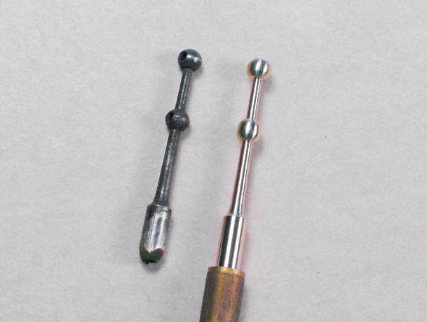
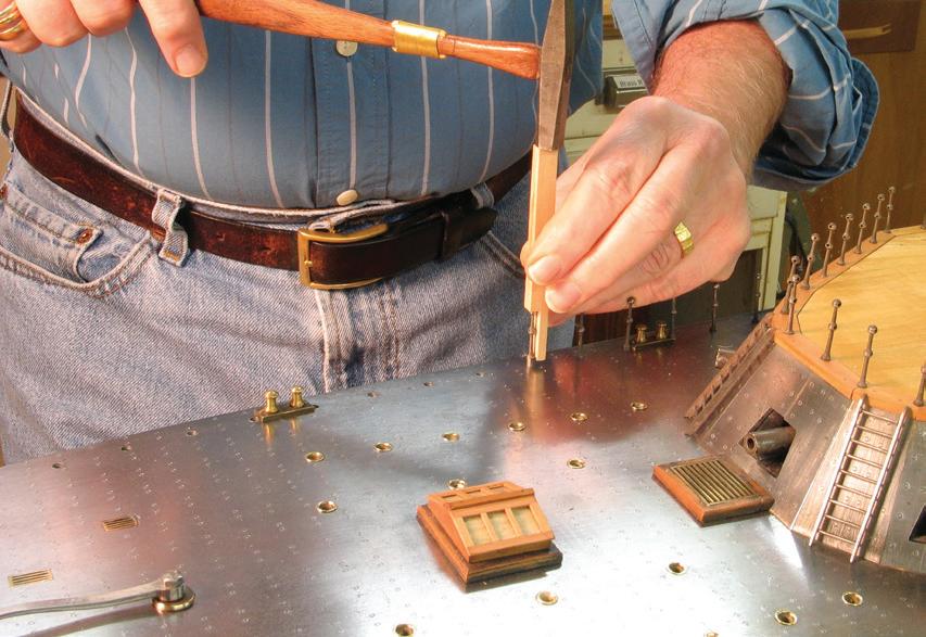
99
An original lifeline stanchion (left), and the one replacement that was required.
Driving the lifeline stanchions with a jig assured they all extended the same height above the deck. Notice the aft-facing emergency tiller; ahead of it is the rebuilt skylight.
Case Study 13
Unidentified about 1870: American Down Easter Modern Unrigged, Full-Hull Model
One day, Bill Partridge, the second proprietor of Piel Craftsmen in Newburyport, Massachusetts, telephoned to report that a model in which I might have an interest had come to roost in his shop. I meandered downtown to have a look. The model lay in a tired cardboard box, wrapped in crinkled, yellowed, and probably acidic paper. Several factors presented themselves immediately. Partridge had an unfinished model of an unidentified vessel by an unidentified modeler. Portions of it were in disrepair, and it had no display or support mechanism. The hull was all there was. Built in the plank-on-frame style, the hull was just the frame with no planking. It was dark, unpainted wood that appeared fairly clean. Except for mast locations, the vessel’s rig was not expressed at all. Nonetheless, it was an engaging, well-crafted vessel portrait created by a modelwright who understood the geometry and structure of his subject.

The model mounted on its new baseboard. There are no indications of decks above the framed main deck except for the pawl and stern posts. There are three hatches, but no indications of other deck structures. There are three mast openings, but no channels.
Let’s go back in time for a moment. In the 1930s, Ed Piel was a young Newburyport man. Perhaps because of being restricted from more vigorous activities by toddler-age polio, he developed a deep interest in ship modeling that gripped him for life. In 1938, Piel teamed up with two brothers named Atherton to form an outfit called LaBaron-Bonney that primarily offered ship models and maps. In time, the modeling flourished while the mapping waned. By 1952, Piel had morphed the ship modeling side into independence as Piel Craftsmen. He operated in a small shop behind his home. The business remained there for several decades, at times employing up to seven people, occasionally operating retail outlets in other locations, and producing a reported, and stag-
gering, thirty thousand models. When Piel approached retirement, the business was purchased, in 1995, by Partridge, another Newburyporter, who had worked during his 1960s-era high school years for Piel before studying engineering at university, serving in the Navy as a Seabee at Da Nang, and having a career in telecommunications. He was looking for something to do in his own retirement, and, like Piel before him, was infected with the ship-modeling bug, for which there is no known vaccine. Partridge moved the shop, still called Piel Craftsmen, to downtown Newburyport in 1996. He continued to produce models that Piel designed, and provided broad support to the region’s ship modelers and enthusiasts.55 In 2020, Partridge closed the Newburyport shop and moved the business to Norfolk, Massachusetts.
Partridge recollected being told that, in the late 1940s or early 1950s, Piel had accepted this model in lieu of monetary payment for a job. Partridge didn’t remember and perhaps never knew the customer’s name, but he was also from Newburyport. In about 2008 or 2009, Partridge was approached by Ted Piel, Ed’s son, about purchasing the model from Ed’s estate; Ed had died in 1999 at the age of eighty-four. Recognizing a good thing, Partridge and Ted Piel made a deal. Partridge asked me to repair the model and to design and acquire a new display for it. In about 2010, Partridge donated the model to the Custom House Maritime Museum in Newburyport, an institution that Ed Piel had helped create.56
The Vessel
Though lacking many details, this unidentified model told us a great deal. With no gunports, it wasn’t a warship. Small hatches indicated a sailing merchant vessel. There was no evidence of deck houses. The hull was full-bodied amidships with scant deadrise, firm but neither particularly soft nor sharp bilges, and topsides that tumbled home just enough to be noticed. Fullness
100
carried toward short, balanced ends that were moderately sharp for their length. The bow had pronounced flare right forward. The three mast locations spoke to the ship rig, but it may have been a bark.
In general demeanor, the vessel’s shape appeared typical of American clipper ships of the 1850s. However, the much fuller ends suggested the likelihood that the model represented the true clippers’ descendants. These vessels were known in their time as medium clippers. Writing in 1929, British sailor and historian Basil Lubbock said,
[American builders] began to build a medium clipper of greater power, yet with a good turn of speed, very strongly put together and economical to work, yet requiring only half the men needed by an out-and-out flyer. These medium-built Cape Horners came to be known as Down Easters because they were all built in the Down East ports — of Maine, such as Bath and Thomaston; of Massachusetts, such as East Boston and Newburyport; of New Hampshire, such as Portsmouth; and of Connecticut, such as Mystic and Stonington.
The designers and builders of these ports managed to evolve a magnificent type of a wooden fullrig ship, which soon became known the world over for her smart, spick and span appearance….57
Additional clarification of why the vessels were called Down Easters was found in William Armstrong Fairburn’s enormous compendium Merchant Sail:
As a general proposition, it could be said that during the early 1850’s fine-modeled, well-sparred and finished ships built for carrying passengers and cargo, to the same general specifications, cost about $70 to $72 per ton in New York, $55 to $60 per ton in Boston, $53 to $58 per ton at Portsmouth, N.H., and from $42 to $48 per ton in Maine.58
In other words, the farther Down East from New York the vessels were built, the less they cost, and we all know cost is a driving factor.
Over time, there has been discussion about the origin of the phrase “Down Easter.” It is generally accepted that these medium-bodied carriers were not so-labeled in their own time, and some notable historians tentatively ascribe the coinage to Lubbock, who used the term several times in 1915 in his first book, Round the Horn Before the Mast. 59 Whether or not the phrase dates from its own time, it now has a specific meaning that can be used confidently. In fact, it can be used with greater surety than “clipper ship,” about which debate also continues, but not here.
Down Easters were the last sailing blue-water carriers in the American merchant marine. They emerged as a class in the early 1860s and fell out of favor with the advent of American steel and steam shipbuilding in the 1890s. These vessels sailed long-range international trade routes and were in effect American East Indiamen.
The model’s two forward mast holes were the same size. This was typical in Down Easters (in which foreand mainmast components were generally interchangeable to save some manufacturing expense and to facilitate repair) but was not as prevalent in the predecessor clipper ships (in which fore- and mainmast components differed). In both types, the mizzen mast was smaller. The model had no channels for standing rigging. If present, their lengths would have revealed the relative amount of standing rigging for each mast. The fore- and mainmasts were certainly square rigged. If the mizzen channels were only slightly shorter, then the vessel was likely a ship. If the mizzen channels were substantially shorter, the vessel was likely a bark. We’ll never know. There was little likelihood that the model represented a barkentine or a threemasted schooner, the other rigs possible with three masts.
Size and Scale
In the American bureaucracy of ship measurement, three principal dimensions were used to calculate a vessel’s registered (or gross) tonnage. These were length, breadth, and depth. On vessels of the sort represented
101
A chart demonstrates the relationship between length-to-beam ratios and gross tonnage in thirty-eight selected Down Easters. The projected plot for the model in this Case Study is the lowest one on the left.
by this model, contemporary sources agreed that length for tonnage was measured inboard, along the upper deck (or the “second deck from below” in three-decked vessels). They also agreed that the forward measuring point was the farthest extent forward of the deck plank alongside the stem. But sources defined differently the aft end point. As examples, Henry Hall placed it at the “after part of the rudder-post,” while I. R. Butts placed it “inside of the plank on the stern timbers.” These were
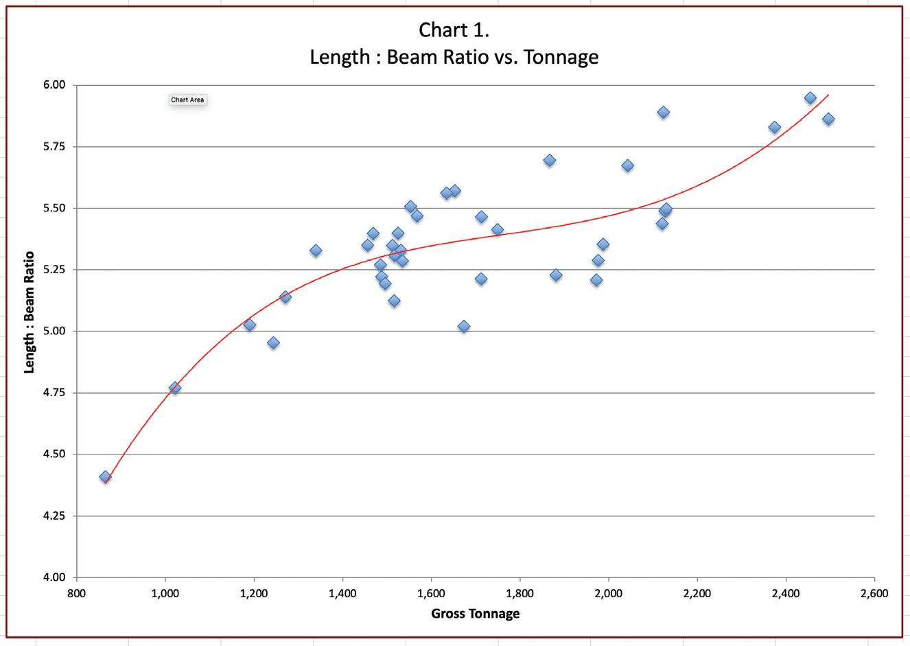
not the same, especially for vessels with long, overhanging sterns where there might have been several feet between the rudder post and the stern timbers. There were no differences about the other two tonnage dimensions. Breadth was measured at the widest part of the hull outside of planking, excluding appendages like channels. Depth was the distance from the top of the ceiling plank alongside the keelson to the underside of the upper full-length deck amidships.60
By Hall’s measurement system, the model’s tonnage length was 27⅛ inches, and by Butts’s it was 2713/32 inches, a difference of just over ¼ inch. In a model this
size of a vessel the size of a Down Easter, the difference would only be about a scale foot or so, which wasn’t enough to skew calculations. I chose Hall’s figure for length because it was slightly easier to work with and because, working for the federal government, his definition was more official.
The model’s breadth was 61/16 inches. Its depth was 3½ inches. The breadth and depth required adjustment because the hull lacked planking and ceiling. Being generally familiar with Down Easters, I felt safe estimating, for a start, that this hull measured about 1,000 gross tons. Hulls of such vessels of this size had 4-inchthick exterior plank and 5-inch ceiling.61 To reduce confusion in the following discussion of size and scale, we will abandon the use of feet and inches in favor feet and tenths, expressed with a decimal.
It seemed safe to assume that the model was built to a conventional scale. The most likely was either 1:96 or 1:64. Because it was more commonly used, I opted to work first with 1:96. At this scale, the model’s dimension for length converted to 217 feet. The breadth converted to 48.5 feet, but this had to be adjusted to include the plank on each side for a maximum beam of 49.16 feet. Adjusted for the ceiling, the depth converted to 27.6 feet.
For another project, I once made a study of thirty-five Maine Down Easters built between 1869 and 1893; I still had their dimensions. For more perspective, figures for three Boston-built Down Easters I’d also studied were added to the mix.62 In all, the thirty-eight ships ranged in length from 164.0 to 266.5 feet, in beam from 34.0 to 44.8 feet, and in tonnage from 963 to 2,495.
The average breadth for the four vessels on each side of the model’s 217 feet was 40.9 feet. At 1:96, our subject’s breadth of 49.16 feet was about 17 percent larger than that average and seemed way off kilter.
Could this data help determine the model’s scale? The method that came to mind was to compare lengthto-beam ratios. This ratio expresses the number of times the length of a vessel is divisible by its beam: A vessel
102
Length : Beam Ratio vs. Tonnage Gross Tonnage 800 1,000 1,200 1,400 1,600 1,800 2,000 2,200 2,400 2,600 6.00 5.75 5.50 5.25 5.00 4.75 4.50 4.25 4.00 Length : Beam Ratio
200 feet long and 40 feet broad has a length-to-beam ratio of 5:1, or simply 5.63
How did the length-to-beam ratio relate to vessel size generally? To find out, ratios for the sample vessels were calculated and plotted against their tonnages. The slope was shallow, but it was clear that larger vessels were relatively narrower than smaller vessels. Also, according to the computer-generated trend line, it appeared that, in samples under about 1600 tons, the ratio diminished more quickly as tonnage diminished. That is, the smaller Down Easters were, the beamier they were for their length.
The model’s length-to-beam ratio was 4.41. In the sample vessels, however, the average ratio was considerably larger at 5.37. The model was too beamy for its length. Did this mean that the model did not represent a Down Easter? Or that the Down Easter represented by the model was much smaller than anticipated? When the model’s 4.41 length-to-beam ratio was plotted and the chart’s trend line was projected, they met at about 865 tons. This was small for a Down Easter, but not impossibly so, especially for an earlier example.
The devil, it’s said, is in the details. So, to avoid jumping to a conclusion about scale, let’s consider another factor: the height of the bulwarks. The top of the main rail on vessels of this sort was generally about 4–5 feet above the surface of the deck. Correcting for the missing deck and rail with 1:96-scale dimensions, the height of the bulwark was about 6.24 feet on the ship.
It looked like, at 1:96, the bulwark height was too great for average Down Easters. When this realization was combined with the pudgy length-to-beam ratio, the scale of 1:96 became improbable. It was time to accept that the vessel was smaller and that the model had been built to a larger scale.
Dimensions were crunched for the model at two larger scales, 1:64 and 1:76.8 (5/32"= 1'). At 1:64, the ship would have been just 144.66 feet long and 32.83 feet in beam. Its bulwarks would have been lower than normal at 4.16 feet. At 1:76.8, the ship would have been 173.6 feet
long and 39.4 feet in beam. The bulwarks would have been about normal at 4.9 feet. While the 1:76.8 heights were good, the model’s 4.41 length-to-beam ratio was far more compelling at 1:64 for a smaller vessel, so this was the scale I concluded that the original modelwright had in mind.
Construction
The original modelwright designed the model’s plankon-frame style to mimic actual vessel construction. For the most part, the model was constructed of mahogany. For some reason known only to him, the deck beams alone, but not the carlins or ledges, were red cedar. The beam shelves and other internal longitudinal timbers may have been oak, but I wasn’t sure. The model appeared to represent the complete frame of a vessel. The frames were double-sawn. Most were full and crossed the keel, but at the bow and stern there were proper square and canted half-frames. There were hawse timbers and lovely fillers at the bow and horizontal transoms at the stern. The futtocks sided 3/16 inch, while the room and space were irregular but averaged ½ inch.
From the quarters forward to where one might expect to find the aft end of the topgallant forecastle, one top timber of each double frame was cut down to the planksheer and the other was left standing to be a timberhead for the bulwarks. From there to the stem, all the top timbers were left standing. They were not all finished to an even height. There was no main rail. However, surviving starboard quarter fashion pieces revealed that the rail, in plan view, curved softly from the sides to the stern.
The stem was fashioned from two timbers separated along the rabbet. The timber ahead of the rabbet was sided the normal thickness of the stem. The timber abaft the rabbet was sided to the width of the opening between the hawse pieces for the bowsprit. This wasn’t typical construction for a stem in a vessel of this size. The technique negated the need for the modeler to fit stem filler pieces and to cut the complex stem rabbet,
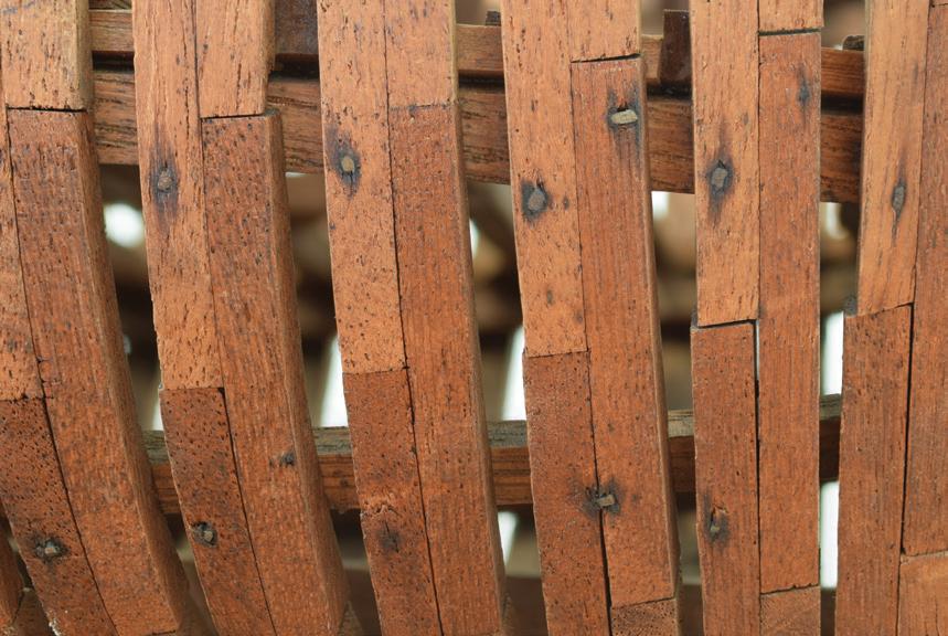
The frames are double-sawn and held together with steel nails of varying sizes. There does not appear to be any glue in the construction; note the clear gap between futtocks at the arrow.
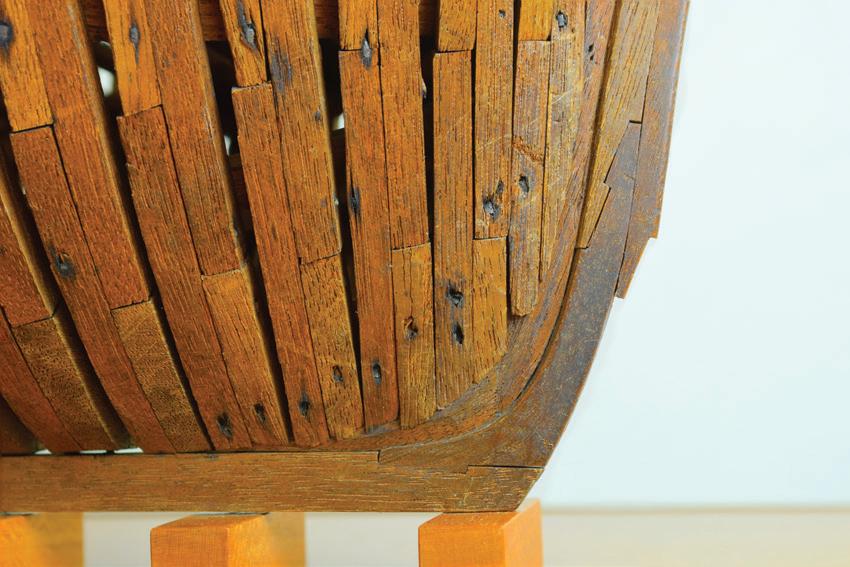
103
Nails secure frames to the deadwood at the bow. The seam between the two pieces of the stem is visible (arrow). Note the hook scarfs in the stem and keel. The gripe was missing; I didn’t replace it because I didn’t want to guess about its original shape.

much as using false stems does in some kinds of small boat construction.64
There was no rudder, but the upper 1½ inches or so of the stern post’s aft face and adjacent portions of neighboring timbers were grooved roughly for a plugstock rudder as if the modelwright intended to true them up later in the building process. That’s what I’d have done.
The planksheer was nicely through-mortised for each regular timberhead. Forward, the frames were closer together and their cant and flare created a difficult geometry for plotting the mortises. Here, the modelwright’s solution was to cut a long slot in the planksheer to form two legs. One leg was bent around the frames’ exterior to the stem rabbet, and the other faired against the frames’ interior. Only the exterior leg on the port side survived. The other three legs forward and the planksheer on both sides near the quarters were missing.
Framing was present for full-length main and lower decks. But some timbers were missing. There was no hint of framing for a topgallant forecastle other than the still-standing top timbers way forward and a tall post on the centerline for a windlass’s pawls. Aft, the stern post stood above the main deck to the height of the sheer, thus indicating that a poop had also been part of the plan. There were no hanging knees.
On American sailing merchant vessels, the waterways were generally left rectangular in section. But on this model their upper, inboard edges were strongly beveled, as those on warships were to allow cannon to roll closer to the sides.65 Here, the port waterway was complete from the stem nearly to the quarter, while only a short portion of the starboard one survived near the bow.
Nails and Other Fasteners
Most of the model was fastened with small nails that were magnetic and, thus, ferrous. With exposed rect-
angular ends about 1/32 to 3/64 inch across or larger, they appeared to have been irregularly handmade in the style of old-fashioned cut nails. If the model was made in Newburyport, a city historically significant in American shoe manufacturing especially during the last third of the nineteenth century, there’s a good chance these were cobbler’s nails, adapted to ship modeling. They were slightly corroded, which helped them do their job because the corrosion bound together the metal and wood. I’d hoped to isolate a nail for study, but it didn’t seem right to extract a fastener just to look at it.
Nails held the futtocks together. The nails were not necessarily perpendicular to faying surfaces but at angles, emerging irregularly in unexpected places, much as knots appear in some wood. Beam shelves were through-nailed to the frames; both ends of each nail were exposed and filed flush to the wooden surfaces, inboard and out. Nails were not used everywhere. The three strakes of narrow topside plank below the planksheer were secured with small wooden pegs or treenails about 1/32 inch in diameter. Their heads stood slightly proud of the planking, a condition likely caused by dehydration of the planks. A few other fasteners appeared to be modern and may have been parts of repairs made by an intermediate hand.
Little glue was found. Older applications were few and probably made by the original modelwright. Brown, hard, and crystalline, it was probably animal glue. However, when it was scraped away to clean up a joint for reassembly, it lacked animal glue’s characteristic odor and stickiness, so it may have been a twentieth-century derivative. The few blobs of another glue were gray and translucent. They were not hard enough to scrape off with a blade; they were tough and had to be carved away, like PVA glues. Old glue was caked irregularly on the aft face of the sternpost, as though a rudder had once been attached. I did not scrape the glue away because of the story it told.
104
The planksheer, shown lifted off its position on the model, was properly pierced for timberheads.
The Work
There were two problem areas. The first involved the stern framing and the second involved the main deck. Fortunately, a packet of parts accompanied the old model.
At the stern, enough remnants survived to starboard to inform us about the transition of shape from the topsides around the quarter to the stern. Framing from the port quarter was off the model. The heel of a single broken stern frame was still attached to the stern post, and eight others had left glue footprints on the wing transom.
The stern’s specific angle of rake could have been difficult to determine. However, one of the parts in the packet was the horn timber (the centerline structural component abaft the rudderstock opening), and it was still attached to the upper remnant of the No. 1 (counting out from the centerline) port stern timber, which had fractured near its lower end. The lower end was the piece still firmly attached to the post. These parts were easy to reassemble accurately
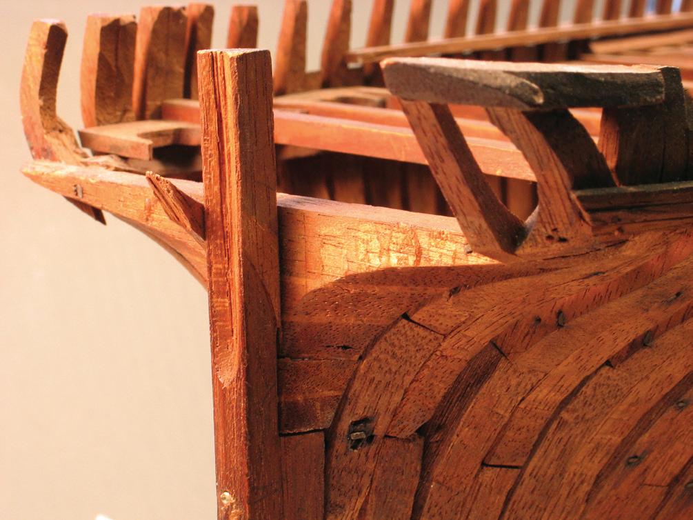
because the break was still jagged and could be knit together precisely and firmly, thus reestablishing the stern’s rake amidships. This was the first actual repair that I made.
Five of the eight other stern timbers were found in the parts bag. Glue footprints and the lengths of the timbers’ legs below their knuckles revealed the parts’ proper order and port-starboard placement along the wing transom. Starboard stern timbers were installed first. It was tempting to think that the heels of the timbers would settle right into their glue footprints to make good joints. But it never works that way. All the old glue must be removed so new joints will meet wood-to-wood. The timbers’ heels were glued to the wing transom with PVA glue. Each timber was held in place by the third hand strengthened with a spring clamp. To fashion replacements for the missing timbers, I traced one of the extant timbers to make an oaktag pattern for the tricky angle of the knuckle between the counter and the stern. I fashioned new timbers from mahogany.

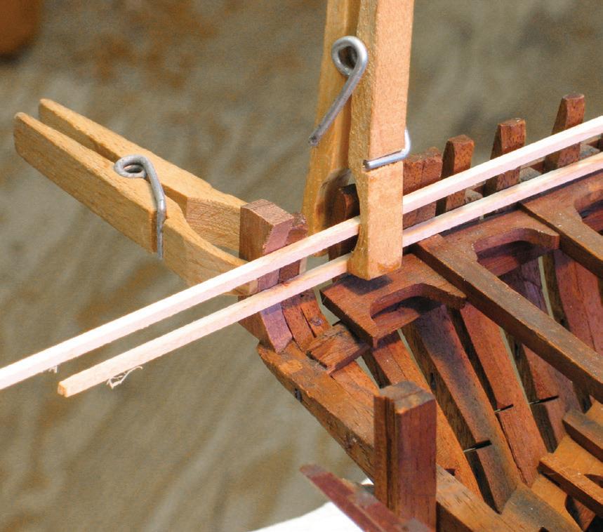
105
The stern before any reconstruction. Dessicated glue footprints on the wing transom (A) and the split frame (B) to port of the stern post helped align parts that were in the packet that came with the model. Note the rough groove in the post for a plug-stock rudder.
Reconstruction has begun. The broken stern frame has been repaired and the horn timber has been attached to it. Two starboard stern timbers are in place. These are all original parts. A modern pin (arrow) had been installed in the stern post by a previous hand.
B
A
C C
A clothespin with altered jaws (A) holds two battens in place that extend the fair shape of the inside of the frame while a new piece (B) is being fit. Notice that each pair of lodging knees (C) is a single piece.
A
B


With the starboard-side geometry re-established, it was time to rebuild the port quarter. Only the timberhead of the aft-most half-frame remained in situ. Fortunately, the quarter fashion piece was in the parts bag. Initial gluing was tentative and only connected its bottom end to the wing transom. I clamped a pair of battens in place on the inboard faces of neighboring timberheads to create a crude matrix for shaping fillers for the space between the surviving timberhead and the fashion piece. When complete, the quarter was reasonably solid.
Another set of glue footprints, these on the aft surfaces of the extant stern timbers just above the knuckles, told me the modelwright had connected the timbers with a single plank across the stern. No marks indicated that this piece had been nailed or pegged in place. Evidence of the previous piece provided the license for its replacement. A single wood strip would have to bend strongly in two ways, vertically and horizontally, to align with the knuckles; the bending would have stressed the joints between the stern frames and wing transom. So, the new piece required spiling to fit
as stress-free as possible. I made an oaktag template to fit the knuckle line, transferred its shape to mahogany, and cut out the piece. I pre-bent the piece to the stern’s curve by rubbing it on a hot, dry soldering iron. After installation, I dressed the piece to its final length.
Deck Framing
Issues regarding the main deck framing were not complex. About seventy deck beams, carlings, ledges, and lodging knees were not in place. I found only eight — two carlings, five ledges, and the starboard half-beam inside the stern — in the parts bag. The others had to be remade. The tricky part was that the locations of some of the original parts couldn’t be determined until other replacements were in. Most of the new parts were mahogany. The only anomaly was the use of cedar for the full-length deck beams and the half-beams inside the stern. I dutifully replaced them with red cedar. The model had appeared reasonably clean initially. When the new mahogany parts were added, though, I had difficulty finding a finish that made them visually

106
Using a soldering pencil to heat bend the counter piece so it will not stress the lower knuckles of the stern timbers.
The reconstructed stern from inboard.
comfortable with the old wood. I found that surfaces within the model were dirtier than I thought. Experimental cleaning with the enzyme technique showed that not just the tops, but every surface of every timber was coated with the yellow-brown grime, that, when moistened with the swabs, revealed the characteristic odor of tobacco smoke. Airborne particulate generally only settles on upper surfaces of models, but smokeborne stuff goes everywhere. When seeing the gunk on swabs, it is impossible to avoid imagining it coating the interior of human lungs. There was no efficient way to clean every surface of every timber. I did the entire exterior, and that brightened the model enormously. The new parts were then treated successfully with a little stain to blend with the old wood. I did not apply any sealing finish to the new work because there was none on the old.
A New Display
Because there had been no satisfactory way to support and brace the model while working on it, making a new

display was the opening act for this job. The contract called for a simple, inexpensive, and noninvasive solution. The model was dark and complex, so the display would be relatively light and plain to contrast with the model visually. Dan Martin was commissioned to build a cherry case with a brass-framed vitrine.
Portraying a vessel under construction, the model would’ve looked silly perched on pedestals or cradles; they would’ve shattered any compelling impression of an actual vessel the model might project. To enhance the piece’s informal nature, I mimicked a shipyard environment with keel blocks. A bilge block and wedge were installed under the turn of the bilge on each side at the dead flat. The keel’s longitudinal alignment was controlled with a pair of small blocks spanning two keel blocks near each end.
Something had to hold the model down. The keel was too fastening-sick and dehydrated for more holes. In one end of a length of annealed 3/32-inch-diameter brass rod, I bent a rectangular hook that fit up, between two frames, and over the keelson. The rod’s other end extended down, through one keel block and the base, where it was threaded and secured with two nuts. In time the exposed brass would tarnish and become inconspicuous
Reflections
When I first saw this model, it immediately summoned to my mind images of the model of the brig Lexington that Charles G. Davis used as his working subject for The Built-Up Ship Model. Published in 1933, over the next four or more decades the book gradually assumed near-biblical stature for American ship modelers. During the same period, the Lexington model became a grail of sorts, sought by but eluding the ship modeling public. I learned from Mainebased ship modeler Neal Parker that the model had been passed down in Davis’s family until his grandson, living in Portland, Maine, donated it to Mystic

107
The dirt on this swab came from cleaning nicotine residue off just half of this deck ledge.
The new display was intended to set off the dark model, to not compete visually with it, and to not put any new holes in it. The simple wooden components are all cherry. The angular brass hook fits over the keelson and secures with two nuts underneath. The pair of blocks spanning two keel blocks keeps the keel aligned.


Seaport Museum, where it was accessioned in 2010. Many ship modelers first attempted to build plankon-frame models by following Davis’s tutorial with Lexington. Davis’s primacy remained intact until the advent of the craft revolution of the early 1970s and the concurrent great leap forward in modern maritime research. By the mid-1980s, Davis’s scheme was eclipsed by the innovative process for plank-on-frame modeling developed by Harold M. Hahn and first published in 1972 in the Nautical Research Journal. 66 The “Hahn method,” as it became known, was the first to substantially eliminate for beginners the fear of experimenting with plank-on-frame construction.
Both Lexington and this Down Easter were built with double-sawn full, half-, and cant frames and with hawse pieces and transoms. Both were left unplanked and unrigged. (However, Parker confirmed that Davis added the bowsprit, lower masts, basic standing rigging, and unrigged cannon to the model after the final photos that appear in the book were made, but that masting and rigging were never completed. 67) I wondered if the Down Easter had been built following Davis’s practicum for Lexington . Other comparisons were inevitable. Davis used walnut for Lexington ’s frame, and I initially thought the Down Easter’s builder had done the same. Some woodworkers say that as walnut and mahogany age they can be mistaken for each other because their grain textures are superficially similar. But when I cleaned the Down Easter, the dark red quality of its mahogany surfaced.
Davis recommended fastening frame futtocks with treenails fashioned from 3/32-inch-diameter sticks from cotton swabs. The strength of the idea was two-fold. First, pegs mimic the use of treenails in actual wooden ship construction, even though Davis’s were about three times over scale. ( Lexington was built at 1:32.) Second, and more pragmatically, wooden fasteners would not interfere with later fairing of the frames or fasteners for other parts. In
the Down Easter, as we have seen, futtocks were fastened with steel nails. Maybe the modelwright was following Davis, but knew he would apply no planking, so he used nails. Davis recommended using wood screws to fasten the heels of cant and half-frames to the deadwood,68 but this was done with nails on the Down Easter.
Lexington had four broad, spiled strakes of topside plank below the planksheer and three more improbably wide strakes above the garboard seam. The Down Easter had three narrow strakes bent into position under the planksheer and nothing along the garboard. Davis recommended using two oak timbers for each deck clamp and fitting quarter knees between the clamps and the transom. In the Down Easter, the clamps were each one piece; they may have been oak; there were no quarter knees. In both models, pairs of lodging knees between deck beams and at the partners were rendered as single pieces.69
Other components can be compared, but I will spare you. In the end, Davis may have inspired the Down Easter’s builder. But it seems clear that the latter was comfortable following his own path. The use of the square nails may be the telling factor. By the time Davis produced Lexington in the 1930s, manufactured nails were common and cheap. It seems unlikely that a modeler would make his own nails if it could be avoided. The irregularity of the steel nails indicates they were individually made. This makes me think the Down Easter model might be quite a bit older, but I won’t hazard a guess on a specific age.
Why was this model never completed? It was certainly built well enough to provide an accurate and solid foundation for complete rigging. Did the modelwright simply lose interest? Did he feel he wasn’t doing a good enough job, so he left this project on the reject shelf? Perhaps he felt it was complete because his goal was, in fact, an unplanked and unrigged model. We can postulate, but, in the end, we’ll never learn his intention. ¯
108
These images are of the landmark model of the American brig Lexington by Charles G. Davis. Some components were added to the model after it was used in The Built-Up Ship Model, but it has never been fully rigged. Notice the figure in white trousers near the helm. (MSM 2010.4.1; photographs courtesy Mystic Seaport Museum)
The firm of C. & R. Poillon “began as a shipyard and sawmill located in Brooklyn [New York] at the foot of Bridge Street on the East River, where it eventually employed three hundred men and also owned wharfs and a yard in Gowanus, South Brooklyn.” The yard built a wide variety of vessels. As it happened, the brothers Cornelius and Richard Poillon were on the board of directors of the Webb Academy for Ship Builders, which later became Webb Institute.70
The brothers built a keel schooner yacht named Belle in 1870 for J. P. Gardner, a member of the Eastern Yacht Club in Marblehead, Massachusetts. She measured 57 feet 5 inches overall and 48 feet 6 inches on the waterline To determine the model’s scale at 1:24, I compared its dimensions with those of the vessel in Fox’s Yachting Annual for 1872. (Fox’s was the first American yacht register, in 1872, to include and standardize information for yachts from many clubs.71)
This may have been the Poillon’s original halfmodel with the addition of a decorative stem, keel, sternpost, and rudder. But it is also possible that this was a decorative model built later. The model and two brass nameplates were mounted on a simple mahogany backboard with a beveled edge.
The model was coated with the evidence of tobacco smoke, splattered with paint, and moldy. In 2012, I cleaned it in the usual fashion. Not wanting the brass plates to be too bright, I polished them with NevrDull just enough to remove fingerprints. I fastidiously prevented the wadding from touching the backboard’s finished surface.
But this story is about something I did not do. A gap had opened between the half-model’s hull and the upper portion of the applied decorative stem. At its forward end, the gap was about 3/32 inch wide. The space was unattractive on a model that was in otherwise fine condition. I wanted to close the gap.
It wasn’t clear what had happened. The original modelwright’s overall level of workmanship indicated
that he probably fit the stem nicely to the hull. That means that either the stem warped away from the hull or that the hull — meaning the forward part of the topsides lift and the bulwark lift — warped away from the stem. But both components were nailed or pinned to the backboard. It seemed more likely that the stem had moved because it was much more lightly built. Being S-shaped overall and having been cut from a single piece of cross-
Case Study 14
Belle
1870: American Keel Schooner Yacht Contemporary Half-Hull Model

grain wood, it had split in two places. But the splits did not affect the stem’s current placement. It seemed unlikely, but I suspected the hull components moved away from the stem. Evidence for this may have lain with the fact that the top of the bulwark lift protruded slightly beyond the backboard’s upper edge by 1/32 to 3/64 inch.
Unfortunately, there was no flexibility in either the stem or the hull. It would have been overly invasive to remove fasteners so the pieces could move. And, even if the fasteners came out, would the wood, now set in its ways, have willingly returned to its proper shape without further fracturing? The gap had been open for some time, perhaps more than a century; it had become a part of the model. It was clear how the pieces were intended to relate to each other. For these reasons, I decided to leave well enough alone after cleaning the model of Belle. ¯
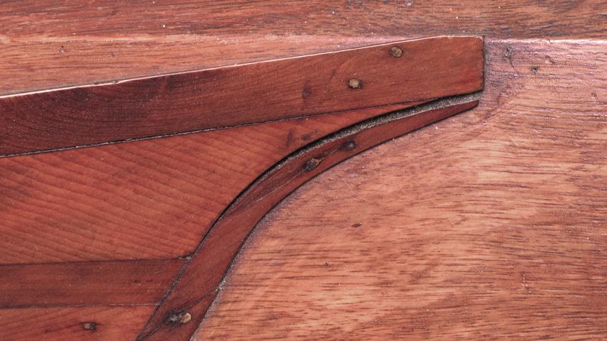
109
The half-model of Belle.
The stem and the topsides lift have parted company, but it’s hard to tell which moved.
Case Study 15
Panay
1877: American Down Easter
Modern, Rigged, Full-Hull Model
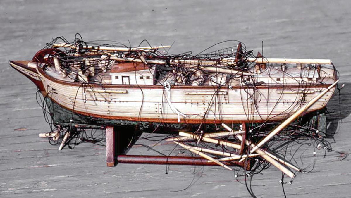
ome nineteenth-century shipbuilders attained such elevated reputations in the pantheon of American maritime history that today they overshadow dozens of builders who also produced superior vessels. Among the marginalized was the father-and-son team of John Taylor and his son Justin E. Taylor. In 1838, John started building ships with a partner. John went out on his own in 1846 in Medford, Massachusetts, then, when deeper water was needed to launch larger vessels, relocated to Chelsea in 1851 and finally to East Boston by 1861. “He turned out ships with remarkable rapidity…. During one year he launched nine.” His “ships numbered some of the best specimens of naval architecture known….” John died in 1877 at seventy after building eighty ships including extreme clippers and Down Easters.72
Justin, the son, was credited with building Panay, a fullrigged, 1,190-ton Down Easter that was launched in 1877. She cost $74,582.75 to construct and outfit. She made global passages to the Philippines to fetch hemp and sugar for Silsbee, Pickman and Allen, a firm located in Salem, Massachusetts, which was her official homeport, but which she never actually visited. Panay was the final ship in a stable of vessels commissioned by the owners from the Taylor yard for the same trade. These ships comprised “…the last of the great East India fleet, which, for over 100 years, had represented Salem merchants and the American flag.” Panay “was considered a lucky ship.” She broke no records but made “steady and consistent passages.” Her luck ran out in 1890 when, during her tenth voyage, she was wrecked while being towed near Simara in the Philippines. All her voyages except the eighth were made
under the command of Captain Stephen P. Bray of Newburyport, Massachusetts.73
This model of Panay was more than superficially reminiscent of the stylistic and ever-collectible prisoner-of-war models, but it was much more recent. Without applying anything like micro-precision, the model’s anonymous builder created a piece that offered the work-a-day character of a robust ocean carrier. So, like prisoner-of-war models, the model of Panay existed fundamentally as a work of art, or, more precisely, of folk art.
As in prisoner-of-war models, if the modelwright had a scale in mind, he did not apply it rigorously. Panay’s hull was 11⅛ inches long on deck and its maximum beam was 2⅞ inches. These distances on the ship were 202 feet and 35.6 feet.74 Rounding, the length converted to a scale of about 1:200, and the breadth to about 1:150. The discrepancy between them was about 25 percent. Another interpretation was that the actual Panay had a length-to-beam ratio of 5.6, whereas the model’s was only 4.2. These disparities eliminate this piece from the world of fine scale models, but they do not detract from its significance as folk art.
It was easy to assume that the modeler had been a sailor aboard Panay. But, according to Ewart Freeston, this was unlikely. In his authoritative treatise on prisoner-of-war models, he inferred that a sailor in a particular vessel would have a greater familiarity with the true arrangement of the structures and fittings on its decks than this model’s builder demonstrated.75 For instance, aboard the ship Panay, the forward end of the trunk cabin was abaft the quarterdeck break, but on the model it spanned the break, and, aloft, the ship set split topsails, but the model shows single topsails.
The model’s hull was a wooden block. Outboard, an overlay of bone planking was nailed above the waterline. There, the bone was inset so its exposed surface was flush with the wood below. Nailed around the hull was a 3/16-inch-wide band of bright shim copper whose upper edge coincided with the bone’s lower
110
S
The model of Panay when I acquired her in 1981.
edge. Bow and stern scrollwork was picked out in red, green, and black inks, but no incised carving. Spars were bone, tops were mahogany. Trestletree-crosstree units at the topmast heads were single pieces of ivory. I believe it was from a whale, as elephant ivory is striated, and this was not. White glass beads were used for deadeyes, blocks, and trucks. Most standing rig systems were represented. Running rigging was limited to lifts, braces, and a few other lines. Fife rails were fitted, but they bore no line remnants, so no running rigging led to the deck. Rigging was different weights of silk or hard-laid cotton. There was no color differentiation between standing and running rigging; it was all black. The model was equipped with other gear as one might expect, but everything was vastly simplified and stylized.
Today, skilled miniaturists building models this size of a ship of Panay’s size readily reproduce nearly all the details that we normally expect to see at substantially larger scales. (See Case Study 5 of Constitution, at 1:192, roughly Panay’s scale.) But Panay’s modelwright did not execute them. Was this because he desired only a more simplistic expression of the vessel, or because the tasks were beyond his skill level? These were good questions, but they were irrelevant to the choices I had to make regarding the renewal of the model. I was committed to the model as it was, to honor it and its maker.
When it came into my hands, the model was terribly dilapidated. There was no indication of any long-term erosion of the model’s fabric from adverse climatic effects, abusive sunlight, or unpleasant creatures. All the damage seemed to be of the same age. There was no evidence of work by any previous hand. So, I suspected the model took a catastrophic nosedive. When it struck, the jibboom shattered in three places. Its heel buckled the oak rail bent around the top of the bow. The rail’s convex surface would have resisted the blow like a curved dam resists being broken by the water compressing its convex, upstream side. The bowsprit was driven ½ to ¾ inch into the space under the top-
gallant forecastle. The impact separated the bone panels at the bow and forced the deck upward. All three lower masts broke at the deck, and many other spars broke. Considering the destruction, it was amazing that only three spar fragments were missing.
Working in 1987, I dusted the model with an artist’s stipple brush. Its stiffness loosened dirt nicely. All bone items were washed with a soft toothbrush and warm soapy water. I felt using water was safe because there were no traces of glue whose holding power would be jeopardized. Still, nothing was allowed to get soaking wet. After patting it dry with paper towels, I set the model under a warm lamp to evaporate quickly any remaining moisture. The bone cleaned up nicely. The glass beads were dipped briefly in a weak solution of bleach and rinsed. But that was thirty-five years ago. Today I would not use the stipple brush, any water, the lamp, or the bleach. Today I’d use a nonabrasive, nylon artist’s brush for dusting, the enzyme technique for cleaning, no heat, and, for the beads, the ultrasonic cleaner.
Spars
Although the model required many everyday repairs, the bone spars commanded the most attention. Let me stress that I repaired them before cleaning them. Take care when matching fragments of broken parts. You can damage delicate edges while mating pieces, especially if they are splintered wood. Align parts correctly before they touch so you don’t work the parts against each other. Use coloration and grime accumulation to guide alignment. If a previous hand repaired a break, clean out the old glue carefully. It’s easier to repair a spar by smoothing the surfaces of a break before joining, but this will shorten the spar. If new material is required, match it carefully with the old. Match the color and the orientations of wood’s grain and pattern. Failure to do this can result in the old and new pieces working against each other physically and visually.
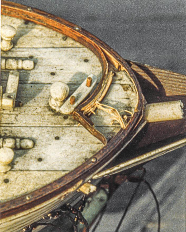
111
Damage at the bow.
The illustration to the right shows examples of some of the twenty-two scarfs I made in Panay’s spars. Sketch A shows a spar that was broken transversely and repaired with a coaxial pin. The pin should be about onethird the diameter of the spar and the depth of the hole on each side of the break should be about three times the diameter of the spar. This is the strongest way to repair a spar, and it is virtually invisible if the joint is tight. But it is hard to drill two perfectly aligned opposing holes. For this reason, ream the mouths of the holes slightly to provide room at the joint for bending the pin to accommodate slight misalignment.
Sketch B shows a transverse break at a hole for rigging. Two longitudinal pins straddle the hole. Sketch C shows the arrangement for two pins if there are two holes in proximity. These pins are necessarily smaller in diameter.
Sketch D shows a more longitudinal fracture. It was repaired with two transverse pins. This doesn’t make as strong a repair as a coaxial pin despite the greater surface area for glue. Further, the ends of the pins show and will require in-painting. Sketch E illustrates several breaks where I used a combination of pinning styles. The longitudinal interior pin was put in with the gluing; the transverse pin was installed later.

Sketch F shows a jagged transverse break near the heel of a lower mast. The hole for the pin was drilled from the end of the spar after gluing the fragments together. This eliminated the need for drilling opposing concentric holes and for starting a hole on a sharp peak of the break.
Sketch G shows how new material was graved in to replace a fragment missing from the spanker boom that had suffered a compound break. The short vertical joint at the bottom was part of the original break. Its
presence preserved the spar’s original length. Because it is exceedingly difficult to fit a graving piece to rough edges, the long edges of the break on both surviving pieces were filed smooth. Then the new material was glued into the resulting shallow, V-shaped notch. Pins were added after the glue set, then the graving piece and pin ends were faired to the spar’s surface.
Sketch H shows a yard with new tip. The jagged edge was smoothed, and a piece of new stock was added to the yard. After gluing and pinning, the piece was dressed to match the yard’s other end.
It’s important to keep pins perpendicular to a joint’s surface (see page 89). With this said, though, in joints requiring multiple pins, I purposefully made them not
112
A D B E F G H C

quite parallel to each other so holding power was increased. I used soft brass for pins because, if the spar should be stressed again, it is liable to break at the same point. A soft pin will bend, but the spar will stay together — frequently it can be bent back into position. A harder pin might cause fractures elsewhere or cause the material around the old break to splinter beyond repair.
In each mahogany top (A, above), material between the lubber holes and the lower masthead hole was broken away. Sketch B shows the rough edges cleaned up and a graving piece installed. Sketch C shows the graving piece faired to the lubber holes and pierced for the square heel of the topmast.
Despite the complexity of the real Panay’s rigging, this model’s creator kept things simple. For me, this meant that rigging advanced rapidly. I used silk throughout because it matched the appearance of the discarded cordage. Ratlines went on quickly because they had been sewn through shrouds rather than clove-hitched to them. Further, they were spaced 3/16 inch apart, much too far for the size of the model. The builder sacrificed credibility here, and it was difficult to refrain from placing new ratlines closer together.
Reflections
A look at the finished model reveals a problem. The components of the hull exhibit a warm sense of folk artiness or, to use modern parlance, funk. None of the same funk exists in the new rigging, which is now true, taut, and cold. The old hull and the new rigging are not happily married — their visual textures are at odds. My question is: How did the model look when it was new? Most modelers set up rigging so it is as taut and shipshape as
possible. The charm in this hull has always been there, but the charm to the rigging probably came later, as it aged. Panay was one of only a few models in my career that I purchased with the idea of fixing up to resell. It caught my eye at a summer marine antiques auction on Cape Cod. The catalog listing for the lot read:
Very fine planked bone model. Of a three-masted ship with real copper sheathing. The vessel is the Panay of Salem. Condition: Unfortunately, the model has been badly damaged throughout its rigging. All rigging is present but needs to be professionally restored. Bow sprit is broken off. Masts are broken off at the deck level. Model appears to be complete and completely restorable and well worth the effort.76
For the record, in this venture I was successful. ¯
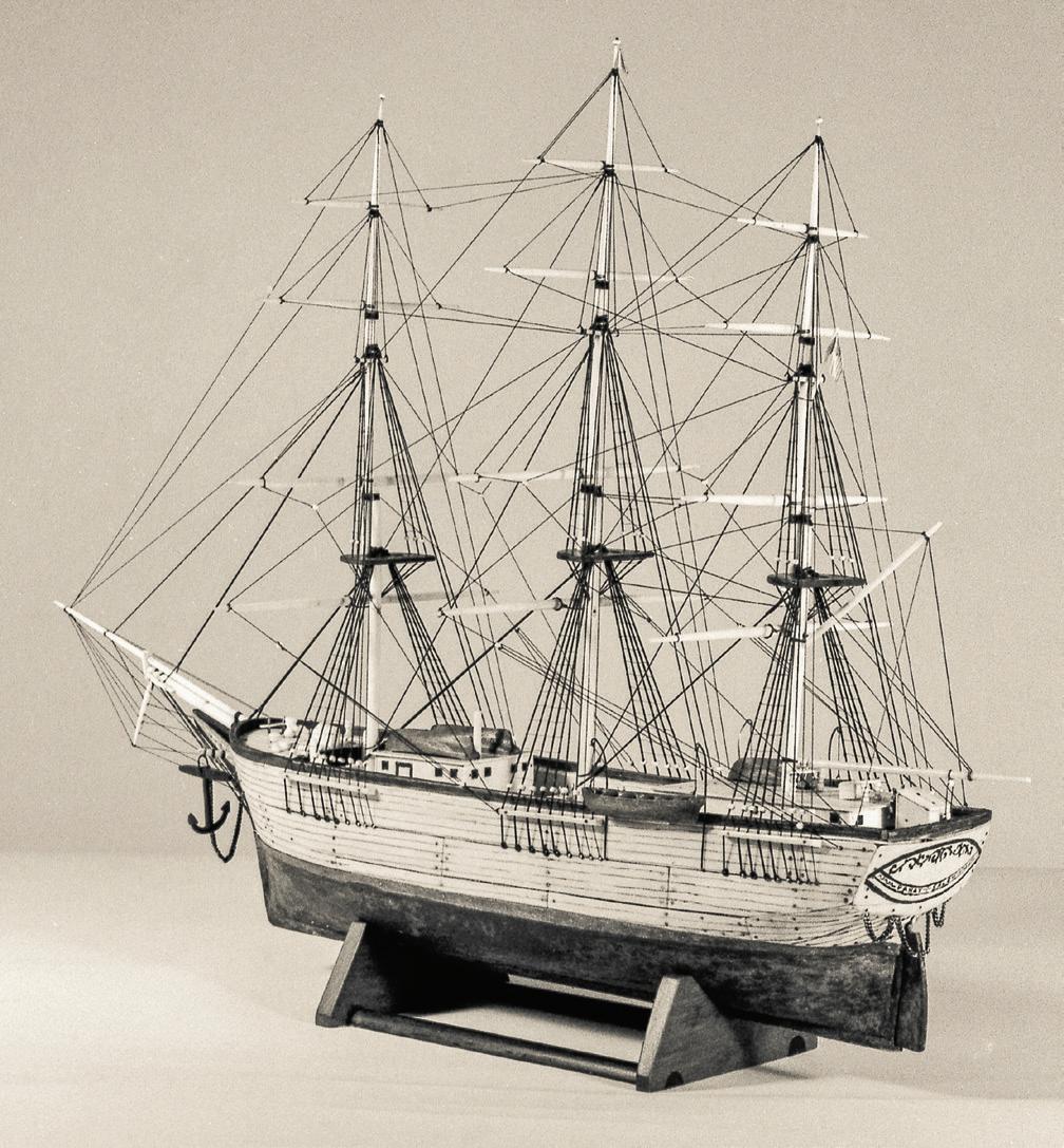
113
A
B C
Case
Study 16 Enterprise
1878: American Cutter Yacht Contemporary Half-Hull Model
EnterpriSe was an attractive mid-sized cutter yacht from 1878. The vessel’s design, according to the brass plate on this half-model’s backboard, was attributed to D. J. Lawlor. However, in the sixteen editions of The American Yacht List in which Enterprise appears,77 Lawlor is listed as her builder. He was likely both.
Dennison J. Lawlor was born in St. John, New Brunswick, in 1824 and emigrated to Boston when he was about fifteen. He initially apprenticed with Whitmore and Holbrook, then was employed by Winde and Clinkard, two Boston shipbuilding outfits. He began creating his own vessels in Chelsea and
was discovered in Plymouth, Massachusetts, in 1865.78 Lawlor died in 1892.
Several Lawlor vessels were celebrated in the late twentieth-century commercial ship-modeling world. As examples, in 1948, Model Shipways of Bogota, New Jersey, started offering a kit of Lawlor’s rakish 1854 brigantine Newsboy. In about 1960, the same company issued a kit of Lawlor’s handsome 1868 New York pilot boat Phantom. And in 1993 and 1994, Erik A. R. Ronnberg, Jr., published a landmark three-part article on Lawlor’s magnificent Boston pilot schooner Hesper of 1884.

East Boston in about 1850. Lawlor was influential in the evolution of vessel design in the maritime region we now know as the “Boston area,” but which was then known as “East of the Cape.” He “was said to have designed 179 steamers in addition to many hundreds of sailing craft,” or perhaps “nearly 500 vessels.” Howard I. Chapelle lauded Lawlor: “No designer has left a more lasting influence on fishing schooners than this man,” and, “He was probably the greatest rival of [George] Steers in schooner design.” This was no faint praise; Steers had designed the breakthrough 1851 schooner-yacht America. Lawlor also found interest in historic vessels; he made a study of the lines of Sparrow Hawk, a colonial vessel dating from 1626 that
The yacht Enterprise was built for Francis E. Peabody of Boston. He owned her for only a couple of years. Then she had a succession of owners in New York and Boston before disappearing from the yacht registers in 1897.79 Enterprise was 50 feet long overall, 43 feet 9 inches on the waterline, and 15 feet 8 inches in breadth. She had a “semicircular transom.” In his book Yacht Designing and Planning, Chapelle illustrated particular aspects of design with the lines of vessels that were not otherwise mentioned in the text. As it happened, he used Enterprise as an example of a vessel with a round stern. Chapelle wrote, “Lines to inside of plank: drawing shows lines as taken of half-model by lead bar method…before being faired.”80 So, this was likely Lawlor’s original model for Enterprise, and its dimensions converted nicely to the scale of 1:24.
The model’s hull was constructed from alternating lifts of two woods. The stem, keel, and sternpost were fashioned from a single piece of pine; the rudder was separate. The backboard was mahogany with a mitered frame. Three or four battens were let into the backboard’s rear surface to help prevent warping; they seem to have been effective. The model and backboard were finished naturally.
This job came to me in 2012. Overall, the piece was in good condition, but it presented a few issues. We’ll
114
The model of the sloop Enterprise. The upper tip of the stem is missing, but couldn’t be replaced because of the backboard’s molding. The matte finish on the dark rudder was modified to blend with the gloss on the rest of the model.
consider the stem first. The grain of the single-piece backbone was principally horizontal, so at the stem’s top the grain was across the run of the timber — not a good thing. The top of the timber had split away at about the height of, but not fair with, the sheer line and was lost. It appeared that the backboard’s frame was applied to its upper surface. My guess is that the loss occurred in antiquity: The stem’s top was sacrificed when the frame was put on. There was now no room to make the stem complete again. The stem might have been made fair with the sheer line if the bowsprit had penetrated the bulwarks. But a photo of the original yacht shows that the sprit passed over the bulwark, not through it. In the end, I decided to not replace the stem head. It would have been jammed against the molding and would look as poorly present as it did missing.
The second item was the rudder. To blend with the rest of the backbone, it should have been pine, but it was a darker wood. Further, its matte finish didn’t blend with the glossy model. Without removing it from the backboard, I smoothed the rudder somewhat, then adjusted the luster of its finish with acrylic gloss medium until it matched.
Third, the hull’s upper surface was spattered with white paint. This was the result of overzealous painting of the ceiling adjacent to where the model was displayed. The good news was that no one had wiped away the paint droplets, so they weren’t smeared. They had landed on the model, beaded, and stuck to the hard, finished surface. It may seem risky, but I have found

that such paint can be removed with an extremely sharp edge tool — I use a chisel sharpened so it will shave my arm hairs or a new No. 10 scalpel blade. I tuck the edge beneath the bead, into the boundary between the paint and the base finish. Usually only a small upward tick will loosen a paint spot, so it isn’t necessary to advance the chisel under the spot. If there are a hundred spots, this must be done a hundred times. Slight residue may be removed by polishing with a soft cloth. If this doesn’t work, 0000 steel wool should do the trick, followed by the soft cloth to reblend the surface’s appearance.
The fourth issue was on the backboard’s back surface. Applied to it was a length of modern masking tape that indicated the model’s display location in a collection. The tape was dehydrated, but its stickum remained slightly gooey. I removed the tape by working the chisel’s edge under it, a bit at a time, being careful not to tick the wood. Basically, I was only cutting the old stickum. When enough tape was lifted to grasp, it was pulled back until it tore. Then the process was repeated until the tape was gone. The stickum was then rubbed away. Screws that held one of the two brass nameplates to the backboard’s front were too long and protruded through the rear. They scratched any surface the model was set on. With heavy cutters, I nipped off the screws’ ends and filed them flush to the surface. Finally, with Nevr-Dull metal polish, I brightened the two brass plates just enough to remove stains from finger oils and to make them a little more readable with the model displayed high on the wall. ¯


Far left. A brand new No. 10 scalpel blade with the edge right on the surface of the original finish is directed at the point where a dot of white paint meets the surface.
Center. The sharp edge of the blade has ticked off the white dot, which is now on the blade. Left. Using a sharp, flat chisel blade to cut through the stickum of dessicated masking tape.
115
Case Study 17
Tioga
1881: American Keel Schooner Yacht Contemporary Half-Hull Model
In 1881, a man named Joshua Brown built the keel schooner-yacht Tioga. Brown was born in Greenland, New Hampshire, in 1828. During his life, he was associated with several shipbuilding and naval architectural firms including “the yard of Currier & Townsend” in Newburyport, Massachusetts. He settled in Salem, Massachusetts, in the early 1850s — that’s where he built Tioga — and died in 1901. A versatile practitioner, Brown became known for merchant vessels, fishermen, small boats, and yachts.81
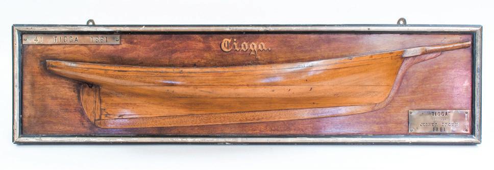
Tioga was 60 feet 11½ inches long overall, 54 feet 1½ inches on the waterline, and 15 feet ½ inch in beam. Her conservatively hollow stem rabbet produced an elegant and proper clipper bow. Her first sails were made by Wilson & Griffin, an outfit located on South Street in New York City. She was built for H. W. Perkins and was registered originally in New York. Her ownership changed five or six times, and she disappeared from the yacht registers by 1900.82
The back of Tioga’s backboard bore the painted legend “Built by Joshua Brown. Salem Mass.” This doesn’t tell us if it was Brown’s original design half-model for Tioga. As pleasant as it would be to think it was, the lack of any obvious way to disassemble the model’s lifts

for measurement and the presence of the head, stem, keel, post, and rudder indicate the model was likely intended to be decorative. The hull was formed of alternating lifts of pine and mahogany; the added centerline details appeared to be mahogany. The model’s upper surface was dressed with an oak veneer. The model and the surface of the backboard were finished naturally, but the latter had a black-painted frame with silver-gilt molding. The hull’s length of about 22 inches converted to a scale of 1:32.
The principal issue presented by Tioga lay with the 1/32-inch-thick oak veneer. Over time, it had separated from the model’s upper lift at two or three split and puckered areas. Dust and old, dried glue had accumulated in the openings and had to be removed to let the veneer lie flat again. This project dates from 2012. To clean out the area, I inserted a No. 10 scalpel blade under the veneer and lifted it gently. Then I used a dental sickle to scrape out the grime much like a caulker would reef out an old seam on a boat. With the dirt gone, the puckers flattened and closed. Opening the seam again with the sickle, I injected fish glue diluted about 50 percent in water under the lifted veneer with a bent-needle syringe.
For a caul to keep the wound closed, I used a stick of softwood flexible enough to conform to the model’s

116
Right. Using a dental sickle to lift the split veneer while injecting diluted fish glue with a bent-needle syringe into the gap.
Far right. Clamping the veneer. A thin pine caul (A) conforms to the sheer, and shiny cling wrap keeps the caul from sticking to the deck. Another pine caul (B) and a white paper towel (C) protect the backboard from the heavy bar clamps.
A B C
The model of Tioga.
sheer and large enough to cover all the puckers at once. A film of cling-wrap stretched over the deck prevented the permanent adherence of the caul to the model. Two heavy clamps pressed the caul down to shut the puckers. Another stick protected the bottom edge of the backboard, where the clamps found their purchase, and soft paper towels protected the backboard above the model. When the glue was dry, the clamps were removed, and excess glue was carved away.
The oak veneer, which displayed a pronounced wavy pattern, had chipped away for several inches along the sheer at the hull’s widest point. A graving piece was needed. With a steel rule and a pencil, I marked straight lines for trimming the veneer with the least loss of original wood. I started to cut the line with a knife along the rule, but the wavy grain caught and wobbled the blade. A wide chisel gave better control.
For the graving piece, I turned to a valuable resource. Years ago, Albert Constantine and Son, Inc., an outfit then in the Bronx, New York, supplied all sorts of fine woods, tools, and veneers to the cabinet-making trade.83 Among their most convenient products for users of small bits of wood was a box of fifty veneer samples, each with an identification label. The variety of colors and visual textures among the samples evoked exotic dark forests on remote continents. Over the years

I made several purchases from Constantine, but none fascinated me more than those veneer samples. In time, many of them found applications in my work — that was the point. This time, the box relinquished a sample labeled Quercus robur, which is commonly known as pendunculate or English oak.
The oak’s grain was not parallel to the sample’s edge, but it needed it to be. So, I sliced a strip off obliquely with a utility knife against the steel rule. Then the strip was trimmed to fit the gap on the model, leaving a good amount extra on the outboard side. The graving piece was inserted, glued, and clamped. When the glue had set, I spokeshaved the veneer to the fair deck-edge curve. Color was adjusted with Minwax special walnut stain applied judiciously with a cotton swab.
Over the years, metal polish had collected and dried in corners and edges around the two brass nameplates on the backboard. The white residue was removed with the enzyme technique. I brightened the plates just enough with Nevr-Dull to remove old finger stains and to make the plates more readable. The upper edges of the backboard had been scarred by screws used to hang the model. I filled the scrapes with LePage Polyfix. Then I faired and in-painted the filler. I didn’t address the areas on the frame where silver leaf had been worn off the molding by brass polishers. ¯
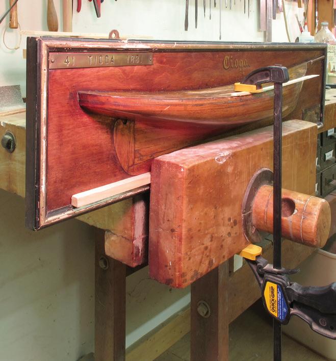
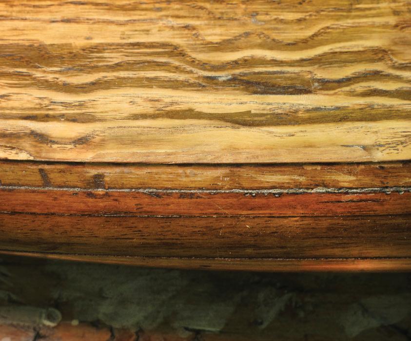
Far left. Fitting the graving piece after the edges of the damaged area were cleaned up.
Center. Gluing and clamping the graving piece. With the model in the vise, the clamp has a good purchase. The pine stick in the vise (arrow) protects the molding on the backboard.
Left. The graving piece has been faired to shape. Its location (arrows) is hard to see.
117
Case Study 18
Corona ex-Colonia
1893: American Keel Schooner Yacht
Contemporary Decorative Half-Hull Model
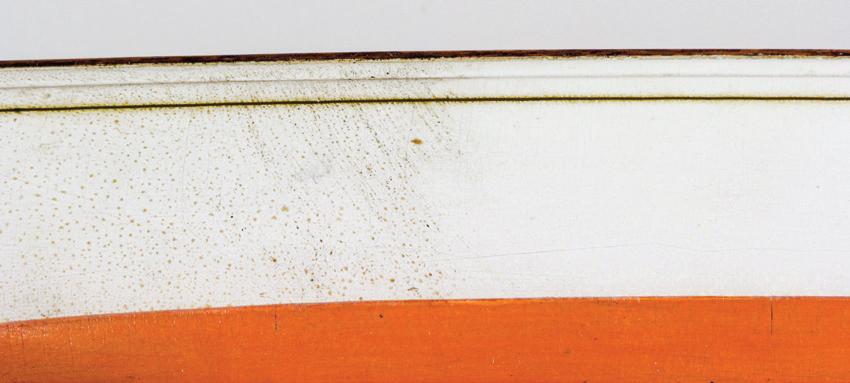
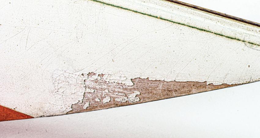
I
n 1893, after a six-year hiatus from a flurry of activity in the 1880s, enthusiasm rekindled in the always-conflagratory world of America’s Cup yacht racing. At this moment, the New York Yacht Club accepted a challenge from England’s Royal Yacht Squadron. The three previous defenses of the trophy had been with yachts designed by Boston’s prolific genius Edward Burgess, but, after his untimely 1891 fall to typhoid fever, new talent was sought. The brightening light was the Herreshoff Manufacturing Company in Bristol, Rhode Island. A New York syndicate headed by Archibald Rogers, commissioned the Herreshoffs to design and build a cutter named Colonia. The Herreshoffs also created a second contender, Vigilant, for other New York owners, and the defense trials ultimately involved two more yachts for a total of four. Colonia lost to Vigilant because Vigilant was more weatherly. Vigilant also beat the other two, won the trials, and beat the British challenger, Valkyrie II, in the 1893 America’s Cup finals.84
Colonia was built as a keel cutter with no centerboard. She was 126 feet in length on deck, 85 feet 6 inches on the waterline, and 24 feet in breadth. Her steel hull was plated with in-and-out strakes, and her original spars, at least, were wood and hollow.85

By December 1895, the Rogers syndicate had sold Colonia to C. A. Postley. He commissioned naval architect A. Cary Smith, who was “successful in designing schooners” to reconfigure Colonia with a centerboard for improving weather performance and to rerig her as a schooner. Intended to make sail handling more manageable by smaller crews, this was “not a very troublesome job” because the Herreshoffs had built in mast steps for just this purpose. The conversions were made for the 1896 racing season. By 1900, she had been renamed Corona, and she was the New York Yacht Club’s flagship through 1902. She was campaigned by various individuals and was last reported to have served in 1930 as tender to the new
J-class sloop Enterprise. She had “[outlived] all of the single stickers of her time.”86
This decorative half-model, whose waterline length of 32¾ inches converted to 1:32 scale, was constructed of three pine lifts. The model seemed light in weight for its size because the wood was substantially dehydrated. The hull had white topsides with a gold cove stripe, a vermilion (reddish orange) bottom, stub masts, and a centerboard. There was no backboard.
The model was dirty. In addition to the normal grime, many small dark dots that may have been mold or mildew covered the painted surfaces. They were most noticeable on the white topsides. They did not respond to the enzyme technique, but they were easily removed with a solution of mild detergent in water applied with cotton balls.
At the bow, a good deal of white paint had fallen away from its substrate, the end-grain of the wooden hull. After cleaning the area, I applied a thin coat of LePage Polyfix to raise the surface to that of the original paint. The filler was smoothed with 220-grit, then 400-grit sandpaper on a block, then it was primed and in-painted with off-white acrylics to blend with the adjacent finish.
The model’s most interesting feature was its centerboard. I’ve noted that the yacht did not have a board originally; it was installed in 1896. On the model, the board had been a panel of wood that was tacked into a long, shallow mortise in the back of the keel. The panel’s grain was horizontal and, thus, parallel to the keel’s bottom. When I first saw the model, I thought the board was missing. But it had broken off along its grain, flush with the keel. The portion in the mortise was still present. The broken edge and adjacent keel area had been in-painted to conceal the break. Unfortunately, the new paint was red and contrasted sharply with the hull’s vermilion bottom.
I wondered if the model had been built originally without a centerboard, as Colonia had, and if the centerboard had been added later, when the vessel had been refitted as a schooner. If this was so, it’s possible
118
Corona’s white topsides before cleaning, left, and after.
the model was made by Nathanael Herreshoff. In his biography of his father, L. Francis Herreshoff reported that Captain Nat made “duplicates for yacht clubs” of models he carved as design tools for vessels.87 Perhaps Captain Nat made this model as a duplicate of his original one for Colonia, and someone else later added the centerboard and the two stub masts.

Regardless, the centerboard required attention. In 2012, I pulled the tacks that retained the remainder of the old board. It was used as guide for the thickness — about 3/32 inch — of a new basswood panel. On the back of the model, an early hand had marked the rake of the centerboard’s leading edge with a pencil line, happily marked “CB”, that extended upward and forward from the bottom of the board’s mortise. I aligned the new basswood panel so its grain was parallel to the leading edge and, thus, crossed the keel’s bottom. It would not split easily, next time. For the aft edge, I used a compass to draw a radius from the approximate location of the board’s pivot. I cut out the board, feathered its aft edge, as the remains of the earlier board had been, rounded all the edges a bit, and primed the wood.
The real trick was matching the bottom’s original color. I worked with a palette of acrylics, keeping in mind that they dry slightly darker than when they are applied. Of course, it occurred to me that I could have repainted the entire bottom, but this would have destroyed over half of the model’s original finish; I didn’t want to do that. I tried matching the color with warmer and cooler red-oranges. I tried working under the complicated amalgam of incandescent and fluorescent lighting in my shop, under each alone, and under natural sunlight outdoors. After eight or ten tries, I finally mixed a color that worked.
Viewers may be puzzled by the bright reddish orange color on the bottom of this model. This is ver-
milion. It doesn’t replicate any color normally found on yacht bottoms. But the color is not coincidental. Models built for some formal collections had their bottoms color-coded to communicate the material with which the vessel was principally constructed. For instance, in 1905, the New York Yacht Club specified that models of yachts built of wood should have natural wood or green-painted bottoms; that composite-built yachts should be depicted by cream- or gray-bottomed models; that iron or steel hulls should be modeled with pink, vermilion, or crimson bottoms; and that models of yachts with bronze hulls should have gold- or bronze-painted bottoms.88 So, the vermilion bottom of this model accurately reports that the Herreshoffs built Corona of steel. (I suspect but cannot verify that many late-nineteenth and early twentieth century formal builders’ models of powered vessels were similarly coded.)
It was not my mission to make this model of Corona appear brand new. The visual textures of the original paint and of minor dings and scrapes offered viewers the notion that this was an old model with history attached. On the bottom, one substantial dent pierced the finish so that bright natural wood showed. The dent could have been filled, smoothed, and refinished, but I elected only to in-paint the raw wood with the vermilion. The bad red paint around the centerboard mortise was shaved away and inpainted, as well. ¯
The back of the unmounted half-hull shows that model was made of only a few pine lifts and how the stub masts and keyhole mounting plates were let into the hull block. The pencil line for the rake of the centerboard’s leading edge is visible (arrow).


119
The remnant of the original centerboard (arrow) and the poor red paint job that was intended to conceal it.
The red painting was removed with a sharp chisel and the area was touched up with hard-to-match vermilion.
Case Study 19
Roxana
1903: American Steam Houseboat Yacht Contemporary Rigged, Full-Hull, Builder’s Model
The Racine Boat Manufacturing Co. was founded in Racine, Wisconsin, on the west shore of Lake Michigan, in 1893, and was noted for creating a wide range of vessels. After a fire in 1903, the outfit relocated across the lake to Muskegon, Michigan, and it finally folded in 1916. In 1903, the yard designed and built Roxana for John W. Gates, a Chicago industrialist and investor.89
Gates wanted his new yacht in New York. Her progress along the Mississippi River and Gulf Coasts was followed in Mid-Western papers. In November 1903, it was reported that the “17-knot” yacht Roxana was “cruising down the Illinois and Mississippi Rivers” on her way to “Port Arthur, Texas, where Mr. Gates had his winter home.” Although she was still in the interior in December, there was concern that Roxana had “foundered in recent gales and that all were lost.” But she arrived safely in New York City in April 1904 after a passage from Wisconsin of one hundred seventy-seven days.90

Roxana was unusual: an elegant houseboat yacht. She was powered by twin triple-expansion steam engines that turned propellers in tunnels beneath her shoal-draft steel hull. As originally built, she was 97 feet long, 17 broad and, amazingly, drew only 2 feet 6 inches of water. She registered 99 gross tons. After her first year, Gates had her lengthened to 115 feet91 in New York. The initial puddle-floating 2½-foot draft gradually deepened: by 1908, it was 31/3 feet, and in 1911 it was 3½ feet, where it remained.
In 1906 or 1907, Roxana was acquired by Larz Anderson, a diplomat and philanthropist of Boston, Massachusetts, and Washington, D.C. Although he kept the boat in New York during the off seasons, she was used primarily in shallow, protected Southern waters. He chartered her to others.92 In 1916, Roxana made a lengthy cruise from New London, Connecticut, to
Key West, Florida. Anderson’s wife, the author Isabel Perkins Anderson, wrote an article about the trip for Harper’s Bazaar. It was directed toward genteel women, and for them she briefly described the yacht’s interior, which sounds more than comfortable:
My stateroom is in the centre, next to the dining room, quite large and very comfortable; forward are four staterooms and bath, and a tiny library. On the upper deck there is a sort of den and plenty of space for lounging. The dining room, which will seat eight persons, contains the little piano that had travelled all over America with us.93
After about twenty years with the Andersons, Roxana’s ownership and port of registry shifted to Providence, Rhode Island, then to Gloucester, Massachusetts. She was last registered in 1932.94
The Modelwright
The model of Roxana was signed with a small rectangular plate on the baseboard that read “The H.E. Boucher Mfg. Co., New York, N.Y., U.S.A.” Because he achieved eminence as an American ship modeler, we’ll look briefly at Horace E. Boucher and his career. According to family records, he was born in Messina, Italy, in 1874, emigrated with his parents to the United States in 1884, and became a naturalized citizen in 1890 when he was sixteen. After attending Trinity College (from which he did not graduate), he began work, first in naval architecture, then as a model maker, at the Washington Navy Yard’s Experimental Model Basin, the first American government-run tow tank, which began operations in 1896.95
In 1905, Boucher opened his own studio for building ship models near Wall Street at 95 Maiden Lane in New York City. He was about thirty-one. Within several years the company moved to 150 Lafayette Street in what is now SoHo.96 Soon, his market expanded from naval subjects to include models of yachts, merchant
120
The 1:48-scale, 28-inch model of Roxana by the H. E. Boucher Manufacturing Company of New York. The modeler’s name plate is just visible on the baseboard in the aft starboard corner.
ships, and more. A byproduct of custom modeling was being able to offer an extensive line of fittings, materials, plans, and kits to those who wanted to build their own ship models.
In 1922, Boucher inaugurated a new tenth-floor showroom at 415 Madison Avenue, only a few blocks from the New York Yacht Club, a principal client in Midtown Manhattan. He was dedicated to contemporary yachting: A member of at least four yacht clubs — the Atlantic, Larchmont, Manhasset Bay, and New York — he was on the race, regatta, or model committee of at least three of them. During the 1920s, Boucher’s modeling services diversified farther to embrace operational power and sailboat models, high-performance model engines of several types, and architectural and engineering models. Boucher’s “spectacular” model trains became so highly regarded that their present-day collectors barely recognize his enormous contribution to ship modeling97 (and vice versa!). By about 1930, he had moved back downtown to 126 Lafayette Street, which was a block south of his previous location, perhaps in reaction to the onset of the Great Depression.
Boucher died in 1935 at sixty-two, but his business continued in New York City. In 1949, Scottish-born Paton Lewis, an employee, became president of the company and renamed it Boucher-Lewis Precision Models. By the early 1960s, it had relocated to 36 East 12th Street in the Village, where I visited as a teenager. When Lewis retired in 1975, his son William shifted the business’s custom-modeling operation to Minnesota, where it continues but has converted to industrial pattern making. At about the same time, Arthur Montgomery assumed leadership of the ship model kits and fittings realm of the Boucher empire, renaming it Bluejacket Shipcrafters. Located first in South Norwalk and then Shelton, Connecticut, it moved through several other owners to Castine, Stockton Springs, and, finally, Searsport, Maine, where it also continues. 98
Boucher’s company “produced more than ninety” models for the New York Yacht Club and one hundred
sixteen for the U.S. Navy; both groups still hold these models. The Smithsonian Institution holds another forty or so. An additional ten Boucher models have been accessioned by Mystic Seaport Museum. There are no doubt hundreds if not thousands of others. As of this writing, I have focused professional attention on at least seventy.
At the beginning in New York, Boucher employed only two men, but that number grew quickly, reportedly reaching a hundred. Many of these were German cabinet-makers. At one time, another trendsetting American ship modeler, Charles G. Davis, (who, according to his diary, participated in Boucher’s evidently frenetic 1922 move to Madison Avenue) worked with Boucher “preparing the lines and complete drawings of early historic ships, blue prints of which [would] be available from” Boucher. Boucher also employed Frederick Avery and Joseph Bruzek, who both became caretakers of H. H. Rogers’s remarkable British dockyard model collection at the U.S. Naval Academy Museum. Other Boucher veterans left the Boucher fold to found new ship model kit companies. Among these were Ward Harmon, who started Marine Models in the 1930s on Long Island, and John Shedd and Sam Milone, who jointly founded Model Shipways in about 1946 in Bogota, New Jersey.99 Vincent Castello, a later Boucher employee, established his own productive New York studio in which many ship models were created for the New York Yacht Club and other clients. From the preceding, it is easy to see that Boucher had a long-ranging and lasting influence on American commercial ship modeling. In many ways, he defined formal ship modeling in this country.
Boucher’s business or departments of it have been reported variously as the Boucher Manufacturing Company; H. E. Boucher Manufacturing Company; Boucher Inc.; Boucher Playthings Mfg. Corp.; and other ways. However, all of them are referred to generally and simply as “Boucher.”

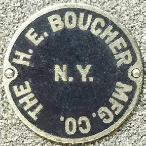

Three plates that identify models built by Horace Boucher and his associates. These would be found typically at the aft end of a model’s baseboard, either on the centerline or in a corner.
121
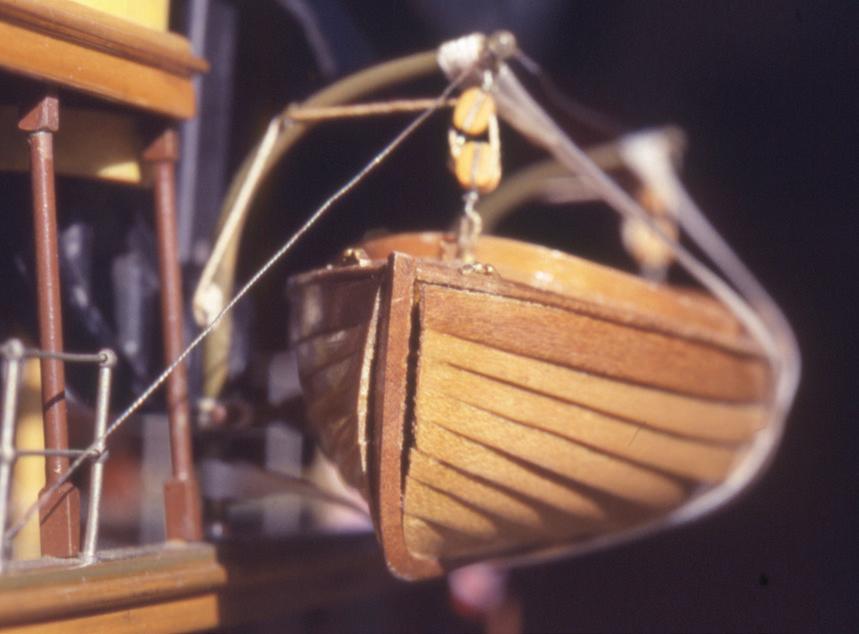
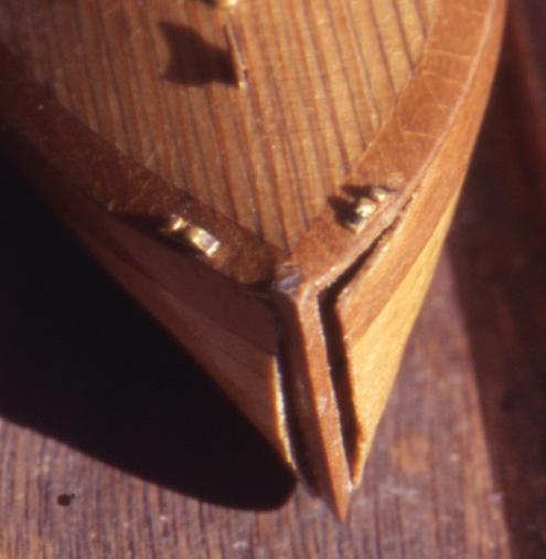

The Model
The model of Roxana’s overall length of about 28 inches converted to 1:48 scale for the yacht after Gates had her lengthened. The heads of two triple expansion steam engines were visible amidships at the main deck level in the open-air engine room.
Various ordinary problems — grime, lead sickness, parted lines, misplaced window glazings, a separated deck margin, and so on — afflicted the model, which I worked on in 2004. But the unique issue that presented itself involved the vessel’s boats. The two largest hung in davits: an open rowing boat to starboard and a partially decked power launch to port. A third boat, a smaller doubled-ended dinghy, was shown cradled and covered amidships at the stern. All were lovely models in their own right, built with individual lapped strakes laid over bent frames and fitted with interior details. At about 4 inches in length, the launch was the largest.
No mechanical fastenings were used in the boats. Their construction relied wholly on glue. Because the models were small, their parts were small; they offered precious little surface area for gluing. On both sides of the two larger boats the glue had failed completely at the hood ends of the strakes — that is, where they meet the stem. In addition, on the rowing boat, some starboard-side seams had failed near amidships.
If the boats had been larger, the obvious solution might have been to nail the planks in place. But such was not possible here. First, there wasn’t enough wood in the stem for even the finest pins. Second, mechanical fasteners would have changed the nature of Boucher’s interpretation of the boats. And third, fasteners would have looked horrid because on the original boats they would have been rendered as inconspicuously as possible. I had to rely on glue, as Boucher had. Any product I’d use would take time to cure, so I couldn’t hold the repairs with my fingers while the glue set up. A jig was required to hold the boat and to provide ways to secure the planks from several angles concurrently.
The jig evolved as I built it. The base was a piece of ¾-inch, dependably flat cabinet-grade plywood. I drew a centerline on the base and glued a pine block to the base on each side to position the launch snugly on the centerline. Two more blocks bracketed the quarters at the sides. Because the pressure on the glue lines at the stem would be toward the stern, a block was glued abaft the transom to be a backstop. Then another, larger block was placed at an angle near each side of the bow. It would have been terrific if these blocks could have pressed the planks directly into the stem. The blocks were flat, but the boat curved. So, I left plenty of room to work small sticks and wedges between the blocks and the planks. The wedges did the actual work.
The glue that held the planks to the stem had failed but had not gone away. Crisp and chunky, it prevented the joints from closing. I carved away the old glue with a No. 10 scalpel. Only when the faying surfaces were clean did I press the planks to the stem.
During the first dry run of assembly, I learned that pressure toward the stern caused by the wedges popped the stern up, out of the jig. The solution was to peg a covering block to the tops of the quarter blocks to lock the boat down.
The images show the yacht’s launch in the jig. The repair was made with PVA glue. A group of sticks and wedges held the strakes’ hood ends firmly against the stem. I left the boat in the jig for more than a full day, just to be sure.
Inevitably some glue oozed out of the joints. The jig and wedges left no room to wipe it away before it cured. After removing the boat from the jig, I carved away the excess glue with a fresh scalpel blade. This worked because the glue remained on the outer, glossy surface of the planking. Had the planks not been finished, and had the glue gotten into their grain, the story would have been different.
In all, this repair was successful. I have kept the jig, although it will probably never be useful again. But who knows? ¯
122
This view of the same boat reveals how the the sheer strake has separated from the deck.
An array of sticks and wedges worked into the spaces between the forward blocks and the hull ensures that every strake is pressed against the stem. Notice the launch’s detailing.
The power launch hanging in its davits on Roxana’s port side. The gap between the hood ends of the upper six regular planks and the stem is visible on both sides. To starboard, notice how thin the beveled ends of the planks are.
DoCtor Saboia was a steel single-screw hopper barge. She was constructed and engined by Lobnitz and Co., Ltd., of Renfrew, Scotland, in 1907, for S. Pearson & Son., Ltd.100 She measured 200.8 feet in length, 34.2 feet in breadth, and 949 register tons. She was powered with a triple-expansion steam engine.
To trace Doctor Saboia’s history, I turned to the Internet site for Lloyd’s Register. A brief historical blurb of the venerable Lloyd’s Register of Ships informed me that it was published from 1764 to 1766, then from 1768 to 1771, and then annually since 1775. It “records the details of merchant vessels of the world.” Starting in the 1870s, the Register tried to include all merchant vessels that were “self-propelled and seagoing, regardless of [their] classification” and more than 100 gross tons.101
I found that many, but not all, volumes of Lloyd’s Register of Ships had been digitized by the time of this writing and are available on-line. Because the volumes were not all scanned by the same organizations, the volumes are not all available at one site. But there are links from the Lloyd’s Register site to a site for each available volume. The volume for 1907, the year that Doctor Saboia was built, had not been scanned. The next available scan included the years 1930 to 1945. Doctor Saboia was

listed in the volumes for 1930, 1931, and 1932. During these years she was owned and registered in Pará, a state in northern Brazil. Then she disappeared. Her fate, whether wrecked or scrapped or renamed, was unnoted.102
Case Study 20
Doctor Saboia
1907: British Self-Propelled Hopper Barge
The 1:48-scale, 52-inch builder’s model had a solid wooden hull that was hollowed in the wake of the large midship hopper area. With many brightly plated metal fittings, the model was handsome and formal in a manner that belied the prosaic duties the vessel performed in her life.
Contemporary Rigged, Full-Hull, Builder's Model
Although over two decades I performed many maintenance chores on this model, I want to bring something else to your attention. The model was displayed in a such a way that it was easy to view from head-on at about normal eye level. One day I noticed that the pink boottop had been painted differently on each side of the bow. Its top edge was horizontal on the starboard side. To port, it swept downward, perhaps to parallel and accent the vessel’s conservative sheer. Was this a purposeful demonstration of two possibilities for painting the vessel? Or was it a masking mistake on the part of the original modelwright? In the realm of bilateral symmetry that is overwhelmingly prevalent in shipbuilding, I think this must have been an error, curious indeed, but an error nonetheless, on the part of the modelwright. Isn’t it surprising nobody noticed? I left Doctor Saboia as she was. ¯

123
Far left. A bow-on view of the model shows the unusual arrangement of the boottop.
Left. The 1:48-scale, 52-inch model of Doctor Saboia.
Case Study 21
Unidentified about 1910: American Schooner Yacht Contemporary Decorative Half-Hull Model

This decorative half-model portrays a large American two-masted schooner yacht typical of those built for racing and cruising in the early twentieth century. Although the model certainly represents a specific vessel, its identity is not known by the current members of the family that had owned the model for a few generations. No lore was associated with it.
In one photo the client sent, a basketball in the background was helpful for determining the model’s size. The ball might have been useful to calculate scale, but the project didn’t go down that path.
The model was constructed like many others of American yachts from those days. The pine hull presented the hull’s molded shape. Above the sheer, the bulwarks were represented by an added piece along the side that left the deck recessed. There was a rudder, a mahogany cap rail, two stub masts, and a stub bowsprit. The topsides were painted white, the bottom green. A cove stripe and bow scroll were painted gold. The portside model was mounted on a plain mahogany backboard with an ogee-molded edge.
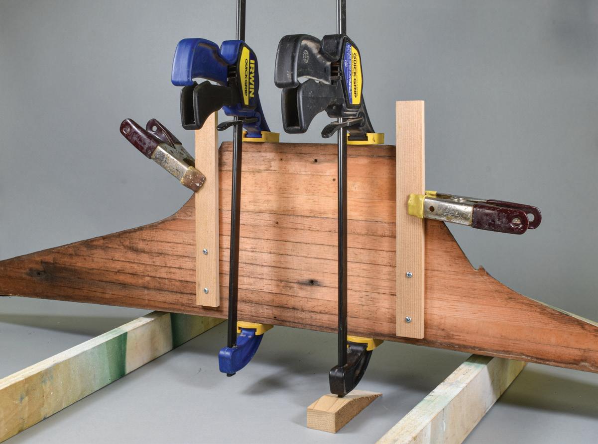
he didn’t want the model stripped and repainted. He wanted it to look lots better, but not perfect or new. This seemed good to me.
The hull was attached to the backboard with four steel, flathead woodscrews that had rusted into place. Steady, earnest force with a screwdriver blade that fit the screws’ slots fully and properly was required to start the screws. When they were out, the hull fell apart at a lift line near the top of the keel.
Above the separation, the lifts were ½ inch thick; below they were ¾ inch thick. There was a slight difference in the coloration of the two sizes of lifts, but not enough to state with certainty that they were cut from different species of wood.
There are two reasons for including this 2021 project here. The first is that it presented an assortment of problems. The most severe was dehydration that caused paint losses and failure of a glue line between two keel lifts. The backboard had been diligently doing its job of protecting the model for a century, but in so doing had sustained many dents and its finish was compromised.
The second reason is that it was important to my client that the sense of the model’s original finish and age be preserved. Although it was dirty and suffering losses,
Because the joint was clean, treatment for the separation was straightforward: Just glue the lift back onto the hull. The joint required clamping, and it was important to maintain the model’s true centerline plane. I didn’t want to use the backboard as a surface plate for gluing because it wasn’t perfectly flat. The solution was to extend downward the centerline plane of the upper portion of the hull. To do this, two ¼-inch-thick softwood battens were screwed to the back of the hull. To prevent splitting the battens, ⅛-inch pilot holes for No. 4 wood screws were drilled. The screws were positioned so they were not on glue lines between other lifts; screws driven in the glue lines could have caused more failures. Old glue was scraped off the mating surfaces of the two lifts. Then they were joined with PVA glue. Two squeeze clamps secured the lower part of the keel to the battens, and two tall Quik-Grip clamps compressed the joint.
For roughly the forward quarter of its length, the hull and bulwark were still securely joined, and I didn’t want to break the joint. So, the seam between them was cleaned out as much as possible with a knife blade and a dental pick. Then the lift was reglued. It wasn’t possible to clamp the bulwark directly to the hull because of its shape. So, for this step, the model was remounted on the backboard, and several wooden blocks
124
The model in a photo e-mailed to me. The battens sticking up behind the backboard were for mounting the model on a wall. The basketball helps define the model’s size.
The arrangement for clamping the two portions of the hull back together. The failure had been at the seam marked with the arrow. The wedge under the right tall clamp keeps the model from falling over.

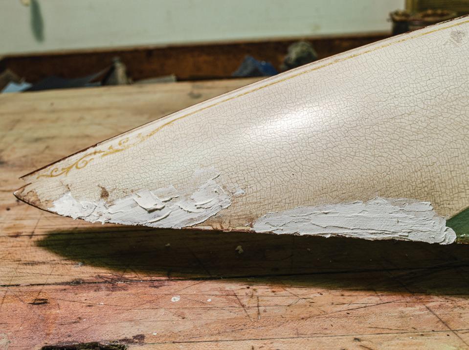

were clamped to the backboard above the model. Then wedges were pushed down between the blocks and the rail to force it against the hull to close the joint.
The model was cleaned with a combination of the enzyme technique and a mild solution of soap and water. Above the waterline, the old white paint had a noticeable craquelure almost everywhere. There were significant white paint losses at the bow, on the transom, and in a spotty area amidships. Lepage Polyfix was applied to fill losses, to fair the surfaces, and to help secure neighboring paint edges. The filler was sanded fair with 400-grit paper, taking care to avoid sanding any surface of the original paint.

In-painting was done with a palette of artist’s acrylic paints. The idea was to approximate the surrounding white color, although it had yellowed differently in different places on the model. Acrylic colors are darker after they dry than when they’re being applied, so some experimentation was necessary. Thinned color applications were made sparingly with a flat 3/8-inch sable brush. Several applications were necessary.
When in-painting the color was complete, it was time to adjust the gloss. I abandoned long ago the idea of trying to mix color and gloss for use in a single application. While matching colors is important, matching glosses is more so. Well-matched glosses can conceal ill-matched colors to a certain degree. For this trial-and-error task, mix equal dabs of gloss and matte media on the palette. Brush the result on an in-painted portion of the work. Let the mixture dry. If the new gloss matches the surrounding area on the first try, you have been lucky. If not, make a new mixture with a higher percentage of gloss or matte, as necessary. When the in-painted area seems to disappear, you will know you have been successful.
There was no work to do on the green bottom paint. The gold cove stripe had been painted along the hull
125
Paint loss at the bow before cleaning the model. Note the faded scroll and the extent of the craquelure.
Loose paint has been removed, the bare substrate primed with B-72, and the area filled with Lepage Polyfix.
The bow after in-painting the white and lightly retouching the cove stripe and scroll.
Cleaning dirt and old glue from the seam between the bulwark and the hull. The gold cove stripe follows this seam.
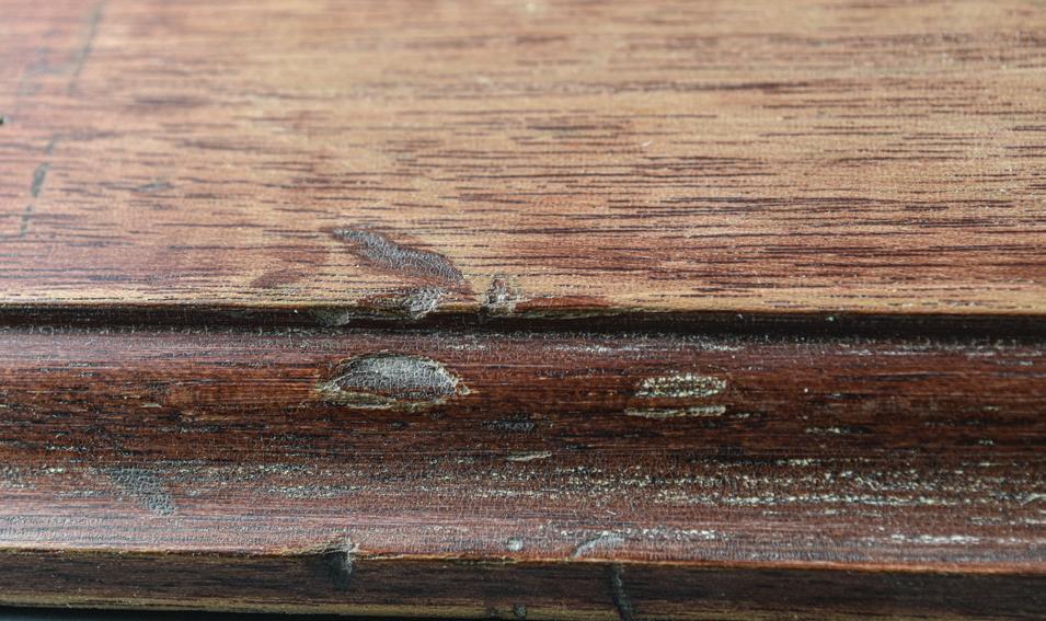


at the same height as the seam between the bulwark and the hull. Thus, the stripe was compromised along most of its length. Rather than making a new surface by filling the seam entirely, I cleaned it up by rubbing away some chipped paint. Then I in-painted the cove stripe and the bow scroll with touches of raw sienna only slightly highlighted with metallic gold acrylic. This kept the gold work subdued.
The backboard looked awful. When I first saw the snapshots that the client had e-mailed to me, I thought the backboard had been painted white and was just dirty. But it turned out the natural finish had oxidized and become chalky. I was able to sand away the whitened surface with 220-grit paper, and this left the original mahogany in pretty good shape in most places. Here and there I had been slightly too aggressive and had sanded through the original finish. I considered stripping the entire board to bare wood, but the client

and I did not want to do that. So, the finish had to be repaired.
We decided to reduce the more severe dents and dings in the backboard. I used Kirby Francis’s method of applying a damp paper towel on the dent, then rubbing the paper towel with a hot electric soldering pencil. This reduced the problem, but did not make it vanish because the method doesn’t work as well if there are broken wood fibers in the dent. He also suggested a method for blending the areas where I had penetrated the old finish to bare wood. Into a paper cup, spray a about a teaspoon of Watco spray lacquer. Add to this a drop or two of red mahogany stain. With a pad — I used a folded paper towel — wipe the tinted lacquer on with an on-off sweeping motion that resembles an airplane making touch-and-go landings. This worked.
When the model came to me, there were two battens mounted on the back of the backboard. They extended above the board and were meant for hanging the model on a wall. They didn’t look good, so I removed them. I replaced them with a pair of keyhole hangers (like those marketed by Hillman) mounted in mortises that I centered 32 inches apart (to aczcommodate standard house framing) in the backboard’s back. When the model and backboard were reunited, they presented a patina of well-preserved age. The client was happy and so was I. ¯
126
The finished model.
A damaged area along the upper edge of the backboard before it was cleaned.
Treating the blemish on the backboard’s front surface with a hot soldering iron on a paper towel dampened with water.
The damaged area after treatment isn’t pristine because wood fibers had been broken, but it looks a lot better.
uring the period from 1903 to 1915, the Herreshoff Manufacturing Company in Bristol, Rhode Island, produced seven majestic steel schooner yachts. Morton F. Plant, a Connecticut-based railroad and shipping financier, ordered the first, Ingomar, and fourth, Elena. Measuring 136 feet on deck and 26 feet 8 inches in beam, Elena was neither the largest nor the smallest of the group. However, built in 1911, she was the near twin of the third, Westward, which had come out in 1910. Although fitted with comfortable accommodations for guests and a professional crew, Elena was built to race. She campaigned consistently in northeastern American waters until the First World War after which her ownership changed twice before she disappeared from American yacht registers in 1942.103
In 1916, five years after the yacht was built, Horace Boucher’s New York studio created two sister models of Elena. They were numbered: The first went to the Larchmont Yacht Club in New York, where Plant was commodore, and the second went to the New York Yacht Club, where he was a member. Prior to or during 1922, Boucher built a third sister model that was retained by the Plant family but was accessioned by Mystic Seaport Museum in the 1930s.104 Our discussion concerns the New York Yacht Club’s model.
The Model
Boucher’s Elena exhibited most of the traits typical of fine-scale builders’ models. What made her unusual, however, was that she showed the schooner heeled to the breeze on port tack with sails full of wind. The hull was sliced at the level of the sea, which was a sheet of glass. Rarely does a ship model have such distinct topsides and bottom portions. The display allowed viewing of the hull’s bottom below the glass and of the rest of the model above it. The 1:48-scale model was about 48 inches long over its rig, but the dramatic presentation made it feel much grander. The hull was solid pine, deck planking was ruled in ink, deckhouses were
mahogany blocks, standing rigging was steel wire rope set up with operable turnbuckles, running rigging was silk, and the sails were molded fabric. The sails were the models’ particular wonderment because their visual power contrasted sharply with their apparent simplicity. Boucher had developed a process for making them that no one since has been able to duplicate. (Many present-day modelers have produced compelling wind-filled sails, but none of them visually resemble Boucher’s on Elena.)
Case Study 22
Elena
1911: American Schooner Yacht
Contemporary Rigged, Full-Hull Diorama
Without going into detail or speculation, I will report that the case in which Elena was displayed somehow instantaneously self-destructed in January 2007. Display issues were not in my jurisdiction for this job. We need to know only that the disaster nearly destroyed the model. Its 41-inch height above its glass sea had been reduced to about 2½ inches. She didn’t look good.
Principal areas of damage involved the bulwarks; ruled decking; wooden deck structures; metallic fittings; spars; most wire and all fiber rigging; and the eight laminated sails. Repairs to the hull, fittings, and spars are detailed in the treatment report submitted to the client and other institutions that contributed to the research effort of rebuilding Elena. These included the Eastern Yacht Club, Marblehead; the Museum of Fine Arts; and the Hart Nautical Collections, MIT Museum, Cambridge, all in Massachusetts; and Mystic Seaport Museum, Mystic, Connecticut. The project’s largest challenge, the reconstruction of Elena’s sails, is excerpted here with permission of the New York Yacht Club.105
Boucher’s sails on Elena were amazing. They looked like one imagines perfect sails on a classic yacht: taught, understated, and quietly powerful. They were made of molded fabric. They were rigid to the touch; the fabric’s weave was faintly visible, but not tactile. Four were 0.017 inch and four were 0.033 inch thick; they weighed between 10 and 106 grams. Other than their overall
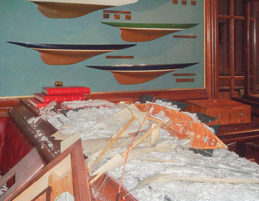
127
D
Elena in ruins. She appears to founder in a tumultuous sea. But it is really shards of tempered glass. (Photograph by the New York Yacht Club)
molded shapes, their surfaces were entirely two-dimensional. They had no actual stitching. On both sides of each sail, individual cloths, tablings, corner reinforcements, and batten pockets were ruled in pencil. Boltropes were not represented. The sails were attached to spars and stays with an appropriate assortment of metal

The composite image for Elena’s memory board. The sockets (A) are the locations of the two wood screws that connect the portion of the model above the sea glass to the portion below. The screws will be concealed by deck houses. Masts mount in the other sockets (B). The foremast broke at deck level; it’s stump is still in the socket.
Pacific.”106 Thus, working on this model was no small event for me. It was an opportunity to worship a hallowed artifact: one of America’s most revered and wellknown ship models.
Frederick C. Fletcher, a Boston collector, had commissioned Boucher to build this model of Flying Cloud in 1915. (For perspective, remember that the first two Elena models were built for Morton Plant in 1916.107) Twenty years later, in about 1935, when he donated Flying Cloud to the Museum of Fine Arts, Fletcher reminisced:
† In 2005, Kurt Hasselbalch of the MIT Museum compared closely the chronologies of Clark’s life and of Flying Cloud’s sailing career. Hasselbalch observed that Clark probably never actually saw Flying Cloud, except perhaps at her Boston launching when Clark was about ten years old. Clark was certainly never an officer in the ship, although he was an officer in at least two other American clipper ships and likely saw dozens more. Thus, Clark had considerable first-hand experience with clipper ships, so probably advised Boucher as well as anyone could.
hanks, sail track slides, and hoops, and fiber lashings. The sails were probably nearly white or light ecru when new but had darkened considerably. They bore no finish, were translucent, and glowed when backlighted.
The sails were fragile. It seemed that, even discounting the recent distress, they may have been near the end of their natural lives. Repairing or conserving them was never seriously considered.
How I assessed Elena’s sails may be established with a glance backward in time. In the late 1950s and early 1960s, I’d become familiar with Boucher’s iconic model of Flying Cloud in the Museum of Fine Arts and his Elena model at the Larchmont Yacht Club. Both models had these compelling sails, and, even in my teens, I recognized that they were made the same way.
In 1992, I had been hired to help prepare the potent ship-model collection at the Museum of Fine Arts for exhibition. I was doing minor work on Boucher’s Flying Cloud. About this “magnificent model,” English marine historian E. Keble Chatterton wrote with his somewhat purple ink that he thought “it would be difficult to find a more perfect combination of artistic craftsmanship and realistic expression of a vessel’s technical details…. The ‘Flying Cloud’ leaps to life as she did in those days when she went racing through the
In 1915 Horace Boucher, the builder of the “Flying Cloud” model, asked me if I was willing to give him an order to build a model of the Flying Cloud at cost in order to carry out a wish of Capt. Arthur H. Clark. Capt. Clark was the author of “The Clipper Ship Era” and other books, and was an officer of the Flying Cloud in her later days…. Clark wished to have a model built and was willing to give his time and the benefit of his knowledge of the Flying Cloud towards the building of such a model.
I agreed to allow Mr. Boucher to go ahead with the model. The building took about eighteen months on account of the sails, which I believe were the first sails of their character ever put on a ship model. In the process of building the model an electric fan was used to get the proper set of the sails and then molds were made and three or four plies of fine cambric were treated with a chemical and set on these molds. All the rigging and sails should be exactly correct because of Capt. Clark’s knowledge of this ship. The lines of the hull were taken from original drawings by the builder, Donald McKay of Boston. So in every particular this model should be an exact duplicate, in miniature, of the original Flying Cloud.108 †
Boucher managed to have Flying Cloud displayed for a while at the New York Yacht Club.109 It seems likely that Plant saw it there and that it was the inspiration for him to order his first two models of Elena. After disaster befell the New York Yacht Club’s Elena in 2007, it occurred to me that the Museum of Fine Arts might benefit from Elena’s misfortune. If the
128
A B B A

yacht club provided samples from Elena’s sails, then the museum could do materials analysis that would teach it about its Flying Cloud without being invasive. In return, the club and I would learn more about how Boucher built his sails.
I approached Mei-An Tsu, a staff conservator at the Museum of Fine Arts with whom I had worked. She agreed to the project and took into custody a few shards from the mainsail that she forwarded to Michele Derrick, an associate research scientist in the museum’s scientific research laboratory.
Knowing from visual examination of the ruined sails that they were laminated of several fabric plies, my specific question to Derrick was, “What agents were used to hold the plies together?” She reported that with an optical microscope she had learned that there were not three plies, as I had suspected, but five (at least for the big mainsail). This must have been news to the museum as well, because in a condition report from a decade earlier, another conservator had observed that the sails were just “two pieces of fabric.” Derrick recognized that the weave of each layer was skewed from its neighbors, so the final laminate worked much like modern plywood in which the grain direction alternates in each ply. The original fabric was a “plain weave, lightweight, loosely woven, cotton cambric.”110 This jibed with Fletcher’s note that said the sails were cambric. The material had a thread

count of “64x64,” or sixty-four threads per inch in the warp and in the weft. The museum’s photomicrograph revealed distinct porosity between the threads. They were quite fine, but no one attempted to gauge them.
Derrick’s report was less clear regarding the method of adhesion: “Infrared analysis indicates the fibers…have been sized with starch. All layers are additionally coated with shellac. Some evidence was found for a protein adhesive between layers.” When asked about the protein adhesive, she wrote that it was “most likely a hide glue, but to distinguish between hide glue and other types, like fish glue, is a rather extensive test.” She added that evidence showed that different plies were probably treated differently during the construction process and that some plies separated from the whole more readily than others.111 In all, the report was extremely helpful, but still confusing. We did not pursue the “extensive test.”
Setup and Materials
I thought naïvely that gathering materials as described by Fletcher and Derrick and making the sails would be straightforward. Only four things were needed: molds, fabric, adhesive, and a way to release the sails from the molds.
Each sail required its own male mold, so there were eight. Their shapes were derived from several sources.

Above, center. Pine blanks for molds for all the sails except the huge mainsail.
Above, right. Carving the mold for the fore gaff topsail.
129
Above, far left. Remains of the shattered mainsail show that the sail was laminated of fabric layers.

These included the original sails’ fragmented remains; Herreshoff’s sail plan for Elena, which was supplied by the Hart Nautical Collections at the MIT Museum;112 photos of Larchmont’s Elena model and of the actual yacht and similar vessels under sail; and card patterns made to fit the model.
The molds were built with 1⅛-inch clear Eastern pine. Most were made from a single piece, but some required two or more pieces that were glued together with PVA glue. No fasteners were used that might damage edge tools later. Outlines were cut with the band saw and sanded smooth. At least one edge of each sail was straight for bending to a spar or stay. The sails’ curved edges were drawn on the molds using a flexible batten. Carving the pine was relaxing because, unlike most ship modeling tasks, it was relatively free-form; aromatic shavings peeled away crisply with miniature bronze spokeshaves and a Stanley No. 9½ 6-inch block plane. I dressed final surfaces with 220-grit paper.
Molds for the mainsail, foresail, and three headsails were made first. How these first five sails set would define the spaces for the last three, so their molds could not be shaped until later. Some molds required minor reshaping when the first sails made on them didn’t fit satisfactorily.
The next challenge was fabric. From the 1930s through the 1960s (at least), Boucher had marketed a “Balloon Cloth” that was “very light weight unbleached…[and] fine quality” for use on pond models.113 My initial thought, which dated back to about 1960 when I’d become aware of Larchmont’s Elena model, was that Boucher’s sails were made from that cloth. I had remnants of it from earlier work on some pond models but now, when I stacked four or five plies together, the total thickness was far greater than we had measured on Elena, and the weave was tight, not open. So, Boucher’s balloon cloth was abandoned — he must have used something else.
A search began for what Derrick and Fletcher had called cambric. I sought an open-weave, 100-percent cotton that was no more than about 0.006 inch thick so four
plies would produce 0.024-inch-thick (or so) sails. If the material was ecru, dying could be avoided. At the Exeter Handkerchief Company in Exeter, New Hampshire, a knowledgeable staff helped me find a white, 100-percent cotton voile from the World Linen and Textile Company in Los Angeles, California. Based on a 9-square-inch swatch, I ordered 15 yards. (Coincidentally, “voile” is a French word for sail.)
An adhesive was required to bind together the fabric plies. It had to cure hard enough to hold a sail’s molded shape, to be sanded smooth for penciling the sails’ seaming, and to create non-tearing edges to support fittings that would connect the sails to the spars and stays. It had to be fluid enough to saturate the fabric. It had to be either brownish or tintable to color the white fabric. (Fabric dying was rejected when a textile specialist couldn’t be located who could promise a consistent job of dying the entire lot with conservator-approved, acid-free dyes.)
During months of testing, I tried many products including a couple of liquid hide glues, carpenter’s brown glues, and even a cyanoacrylate. All had problems. I laminated three plies with spar varnish; the result resembled an over-oiled tortilla fried in a too-hot skillet. I tried PVA glue, but it never hardens enough to ensure that a sail would keep its shape for a century. I tried B-72, but it didn’t have sufficient cohesion. I avoided starch.
Knowing from Derrick’s report that fish glue, which conservators use extensively, may have been in the original sails and has a lengthy open time, I tried it a dozen times; its brown color muted the white cloth nicely. But in every test, after curing for about six hours, bubbles erupted on the sail’s surface. Then there was traditional hide glue, which is fussy stuff. Considerable inconsistencies in purity, even in packets of the same brand, produced mold or fungal spotting in the fabric. I tried two varieties: pearl and granular. The pearl glue was too unpleasant to work with. The granular glue produced generally good results; finished surfaces were hard and
130
Bubbles on a trial sail; this was far from the worst case. To conserve fabric, trials were made on molds used in a different sail-making process for smaller sails on a previous project.
sanded to powdery smoothness for penciling. But bubbles persisted annoyingly. What caused them? In every case, bubbles formed after a sail looked perfect on a mold for about six hours. Everyone I met who understood hide glue shared the opinion that the bubbles occurred when a sail’s outer surface on the mold had dried enough to create a film that could not be penetrated by moisture still escaping from deeper in the laminate. So, I tried laying up sails one ply at a time, letting the glue set between plies. But newly applied hot hide glue reactivated the layer beneath, and bubbles bubbled.
The answer seemed closer with shellac — another animal-protein substance mentioned by Derrick. It is reasonably cohesive if it is wax-free. I invested in a couple of exotic brands of dewaxed dry shellac flake and learned to prepare them in custom-ordered, relatively pure denatured alcohol. Shellac dries as fast as its alcohol evaporates, but reactivates itself, like hot hide glue, with fresh contact. Amazingly, after six or eight hours of appearing perfect, no bubbles developed! But blotches did. What caused them? I never found out.
Meanwhile, I was experimenting with ways to prevent a sail from sticking to its mold. I tried finishing molds with urethane; wrapping them with foil and kitchen-variety cling wrap; and applying microcrystalline and candle waxes. All had problems.
Over time, I tried about a hundred combinations of all the materials and techniques described. I kept a log of the results. Admittedly, some tests produced results that generated immediate elation. But it was always short-lived because those results couldn’t be duplicated or improved upon predictably. Reverse engineering was not working.
The Solution
During the project, Harry Morgan became chairman of the yacht club’s model committee. He began experimenting independently. He reprised various techniques I had tried and got similar results. When he tried using
West System epoxy, the results were rough but promising. Although we would not be using traditional materials, we decided to make a full-size test with epoxy.
West System epoxy has two parts: Resin is mixed with hardener. Their proper ratio is calibrated by proportional pumps that fit the cans, one squirt of resin to one smaller squirt of hardener. At the recommendation of Mike Barnard, a technical advisor at West System, we worked with 105 Resin and 207 Hardener.114 Both are clear, so tinting was necessary. We used a “concentrated dye solution” marketed by TransTint: golden brown No. 6002. After testing, we settled on adding 1½ small drops to each pump-squirt of resin. To ensure that all the resin was tinted evenly, we pumped out the can (counting squirts), tinted the whole batch, and replaced it in the can. That was an afternoon.
A reliable release agent was still required. In an early attempt with kitchen cling-wrap, the release had been slick, but the surface showed wrinkles. I thought that heat-shrunk wrap, like that used to winterize boats, might work. Then Morgan suggested a clear film product that heat-shrinks to frames to form temporary storm windows. A Frost King Window Insulation Kit that included plastic film and double-stick tape did the trick. The film was stretched over a mold, pressed onto the tape around the sides, and shrunk with a hair dryer.
The epoxy tested well. There was neither bubbling nor blotching, color was consistent, and the release film worked perfectly. The epoxy set up hard in about three days. The sail’s surfaces could be sandpapered easily to the desired finish. They were then non-reflective and accepted pencil detailing easily. The best thing was that secondary attempts did not return us to square one, and predicted improvements worked.
The thickness of three-ply sails would have been more in keeping with the originals, but they were not rigid enough. So, we settled on four. The difference was about 0.004 inch: not much. Morgan and I regretted not being able to duplicate Boucher’s materials roster.
131


But we were satisfied with the choice of cotton voile and with the results we achieved for color, visual texture, and transparency. There was a solution, and I could advance.
The Process
A sail was made like this: A 2- or 3-yard length of the cotton voile was laundered in hot water to shrink it and remove whatever impurities it might contain. The fabric was ironed. Then four plies were cut, each being at least 1 inch wider all around than a mold’s working surface. No concern was given to the direction of the weave, but great concern was given to minimizing the amount of fabric that might be wasted. The plies were ironed again, carefully inspected for any surface issues, like bits of thread, and laid out flat on a clean surface without overlapping.
Meanwhile, the double-stick tape was applied as low on the sides of the mold as possible so that epoxy on the fabric wouldn’t adhere to the mold below the film. The mold’s working surface was wiped off immediately before applying the film because even the smallest-seeming mote could leave a pock mark in the sail. Then the film was applied and shrunk. For this and the following steps, the mold was secured by a mounting block in a vise.
The first fabric ply was placed on the mold and stapled to its sides at points roughly opposite each other. Then stapling progressed toward the ends. The fabric was pulled as tightly as possible. There had to be no wrinkles, and wraps at the edges and folds at the corners had to be crisp and smart. The job evoked memories of making my bunk at Navy boot camp. A staple was placed every 2 or 3 inches for each ply. This meant a hundred or more staples were used for each of the smaller sails, and the stapler had to be reloaded during a sail’s layup.
In a disposable plastic cup, two squirts of the tinted epoxy resin and two squirts of hardener were thor-
oughly mixed for a smaller sail. Epoxy was poured on the first ply, spread with the mixing stick, and squeegeed vigorously into the fabric. The epoxy was worked to just over the mold’s edges, but care was taken to keep it off the sides. Extra epoxy was squeegeed off to unify the surface. I placed staples as low as possible on the mold to keep them and the business end of the stapler free of epoxy. Despite this, three staplers were destroyed. Every impurity that appeared within the sail’s finished area was plucked away immediately; it would be impossible later. The second ply was then patted gently to the sticky surface of the first ply to reduce sliding while being stretched and stapled. Epoxy application, saturation, and smoothing followed. The cycle was repeated until four plies were applied. Each smaller sail took about half an hour to build.
The new sail assembly was left to cure on the mold for three days. Then the staples were removed using diagonal cutters and a long awl. To detect staples lurking under overlapping plies, I worked a putty knife under them to the mold’s upper edges. With the staples gone, the sail lifted easily off the release film. The hard sail was trimmed with metal-cutting shears to within about ⅛ inch of its final edge.
After release from the mold, the sail’s bottom, concave surface was glossy smooth from the release film, but the upper, convex surface had a pebbly texture. The surfaces had to be the same. The sail was returned to the mold and was held there by the lip around its edge. The convex surface was sanded with Norton Pro-Sand 120-grit paper to remove every bump and shiny brightness. Then 220-grit paper was used until the surface had a uniform, powdery smoothness. The sail was inverted, placed on the shape-conforming pad of a fluffy old terry cloth towel, and sanded until the concave side had the same finish as the first side.
The first five sails were off their molds and sanded before I proceeded. Meanwhile, the masts had been stepped in the model. Standing rigging had been installed and running rigging had been rove off so the
132
Laying the first cloth ply on the mold for the main (club) topsail. (Photograph by Dawn Rabinowitz)
Pouring tinted West System epoxy on the second ply of the main (club) topsail. (Photograph by Dawn Rabinowitz)
Saturating the fabric and removing excess epoxy with a squeegee. (Photograph by Dawn Rabinowitz).
booms and gaffs hung in their approximate positions. Nothing was permanently set up, but it was time to start fitting sails to the model.
The two gaff sails were first because their placement controlled how everything else went together. And the mainsail had to be the first of the two because securing it to its sail hoops, which were already on the mainmast, would be greatly hindered by the foresail. So, the mainsail was offered up to the spars and studied from every angle. The sail’s set and belly were compared to earlier photos of this and the Larchmont Elena models. When it seemed like everything was okay, the lip around the sail’s edge was trimmed away to the sail’s final size. The lip’s removal allowed some flexibility to the sail that, in turn, let its belly be controlled slightly with rigging. When I was satisfied with the shape, I dressed the hard edges on the table sander so they were straight or curved, as necessary.
Boucher had depicted sail detailing with pencil lines drawn directly on the molded fabric. The work was simple, sophisticated, and clean. The lines could be easily erased; they hadn’t been sealed. A single line around a sail’s perimeter represented the tabling. Other drawn detailing included corner reinforcing patches, and, on the mainsail, three batten pockets. Herreshoff’s original sail plan for Elena depicted a single reef band on the foresail and a pair of bands on the mainsail, but Boucher omitted them. Parallel lines drawn across a sail’s body represented the cloth panels from which the actual sail was built. On Elena, Boucher showed some sails with 15-inch-wide panels and some with 20-inchwide panels. Three sails — the foresail, mainsail, and main topmast staysail — were shown with the cross-cut pattern; that is, their cloths were perpendicular to the leech. The technique was reputedly an 1894 Herreshoff innovation.115 (It had been traditional practice to build sails with the cloths parallel to their sails’ leeches.) Four sails — the fore staysail, jib, jib topsail, and fore gaff topsail — were shown as miter-cut (that is, a seam bisected the angle at the clew, and panels were arranged
symmetrically to the miter and were more or less perpendicular to the leech and the foot). The huge main (club) topsail was built with a sort of hybrid pattern. The large upper portion of it had panels perpendicular to the leech, which was the upper edge. A miter seam isolated the lower corner of the sail, and its panels were about perpendicular to the foot.
Penciled details were copied as exactly as possible from the remains of the original sails. I used a No. 4H lead, sharpening it frequently, in a draftsman’s traditional lead holder. With a sail placed back on its mold, the tabling lines were drawn around the perimeter. This was done freehand using the carpenter’s method of bracing one’s fingers against the edge and dragging the pencil along about 3/32 inch from the edge. Next, the corner reinforcement panels were constructed using a French curve, a straight edge, and an ellipse template. Errors could be removed easily by lightly scraping the penciling off the hard epoxied surface with the curved edge of a new No. 10 scalpel blade. Finally, the sail’s cloths or panels were drawn. I followed Boucher’s lead for panel widths. Once the first seam was drawn, subsequent seams were gauged from it with a length of flexible, 0.015-inch-thick white styrene. For smaller sails, I could hold the strip with one hand, but for a larger sail, the strip was clamped to the sail’s edges, as well.
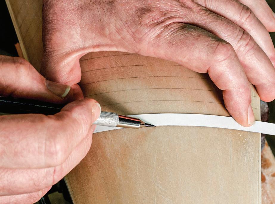
Knowing Elena would be backlit in her final display, it was important that the pencil work on both sides of the sail matched. To do this, I held the sail up to a window so the sun revealed the lines through the sail. Then, on the new side, I made tiny tick marks at the ends and middle of each seam. The sail was then set convex side
133
Lining off sail panels with a 4H lead in a draftsman’s lead holder. A styrene strip gauges the width from the previous panel.


down on the towel pad, and the lines were drawn on the concave side.
Assembly
With the first five sails finished, it was time to begin tensioning the rig. Shrouds for both masts were set up with their original operable turnbuckles. Amazingly, they had survived the case implosion, and they all worked except one screw that had stripped. The turnbuckles were a joy to use, so it was satisfying to adjust the masts.
The stays set up in a variety of ways, but none used turnbuckles. Most were unadjustable. That this was Herreshoff’s intention was expressed clearly on two drawings, one of standing rigging, the other of running rigging.116 The effect of the fixed-length stay system was that the relationship between the bowsprit and masts was immutable once the stays were installed. However, there was a safety. The mainmast and main topmast were fitted with a pair of preventers and a pair of running backstays, respectively, that led down and aft. These were tensioned at deck level by powerful tackles with fiber falls that could be adjusted and cleated easily. This meant the preventers and backstays were the means for fore-and-aft tensioning of the model’s entire rig.
in turn, meant that many (but not all) longer lines had to be replaced with new wire rope.
Boucher had used ecru silk for the fiber rigging. After about a hundred years, silk gets tired. This had been noted in a 1988 condition report regarding Flying Cloud at the Museum of Fine Arts: “The silk rigging is in extremely fragile condition and it will continue to deteriorate with exposure to light.”117 I had noticed, while working on Elena in November 2006, two months before the disaster, that much of her silk rigging was at its failure point. And, obviously, most of it failed or was destroyed during that disastrous moment. It was an easy decision to replace it all.
Over the years, I had hoarded Pearsall’s Chinese “twist silk” in many sizes, both ecru and black. It looked so much like what Boucher had used that I suspected it was close to the same line that he listed in his 1934 catalog as “Silk rigging lines for fine ship model work (Imported Chinese Twist).”118 I was pleased to use some of my dwindling cache on this job.
Bending the Sails

In the disaster that befell Elena, many lengths of the wire rigging were cut or otherwise broken. But many survived, as well. My goal was to reuse as much original material as possible. This meant using remnants of longer cut lines in new, shorter applications. And this,
The mainsail and foresail were the first sails to be installed. The foot of each sail was bent to a track on its boom with 0.016-inch wire V-shaped sail slides. I laced the sails’ heads to their gaffs with silk. Each sail, with its boom and gaff, was held loosely in place while I sewed the mast hoops, which were already on the masts, to its luff with extremely fine French linen. I had pre-drilled holes for these fittings and lacings in the hard-molded sails.
Each corner of nearly every sail was equipped with a clever bent-up wire cringle. The cringle’s legs went through two holes in the sail and were folded back on themselves so the fitting looked the same on both sides. The cringles were for tack lines, outhauls, halyards, and so forth, as necessary. Most of the cringles survived, but some new ones had to be made from 0.016-inch wire.
134
Portions of six of Elena’s eight sails are in this view of the foremast doublings. Ahead of the mast they are, from the left, the fore topmast staysail, jib, and fore staysail. Abaft the mast, they are from the top, the fore gaff topsail (only a sliver of which is visible), the main topmast staysail, and the foresail.
A B C
Original steel wire sail track slides (A), fore staysail hanks (B), and sail corner cringles (C).
Stress on the luff of the jib (which was set flying) was eliminated by lashing the sail to a wire rope luff line (arrow).

The fore staysail was hanked to its stay with tiny, oval wire links. With the fixed-length forestay already rigged and tensioned, the hanks had to be inserted as opened rings through holes bored in the sail’s luff, then closed around the wires. This was awkward work.
The jib went on next. It was set flying; that is, it did not ride on a stay. However, a 0.012-inch-diameter stranded wire rope was stitched with 0.005-inch single-strand wire to its luff so the downhaul and halyard could be pulled taught without stressing the sail. The jib topsail was hanked to its stay like the fore staysail.
Then it was time to build the last three sails. They required fussier fitting than the first five. For the fore topsail and main (club) topsail, poster board patterns were cut, offered to their spaces above their gaffs, and adjusted until they fit. Then the patterns were transferred to the wooden mold blanks, the molds were cut and carved duplicating the processes used on the earlier sails, and the sails were laminated. The fore topsail secured to its mast with hoops like the
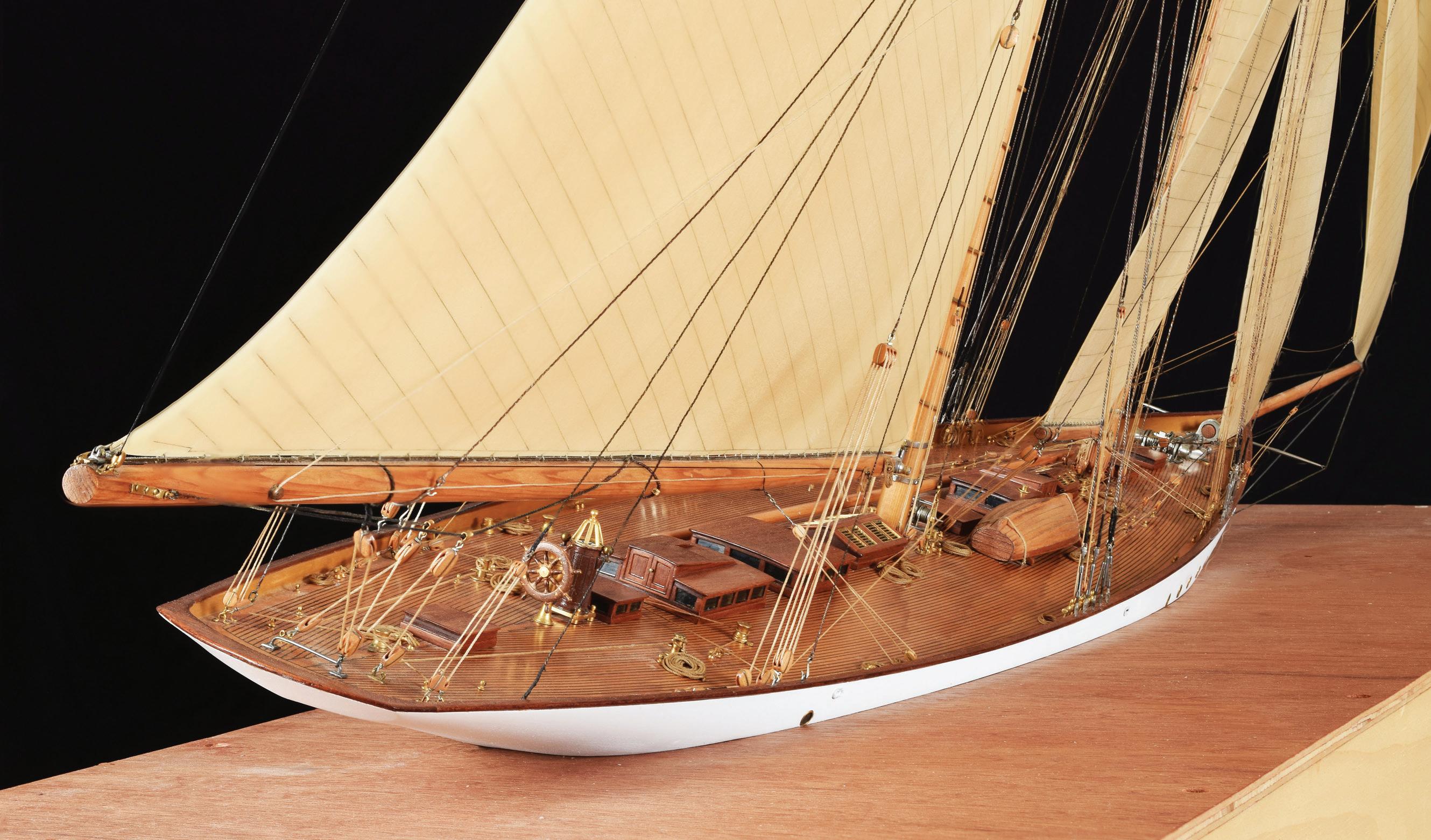
mainsail and foresail. The main (club) topsail’s luff and foot were attached by slides to tracks on the sail’s yard and club. (The yard was the vertical spar along the topmast, the club was the lower spar along the gaff.) The last sail was the main topmast staysail, and it was by far the most difficult. It was set flying, like the jib, without a stay. Further, it had to fit between the masts and other rigging, and it had to extend outboard of the starboard main spreader. Because of its weight, the installation of each sail changed the stresses on the rig, so the standing rigging required continuous adjustment.
The hard part of this job was concluded with the installation of the last sail and its rigging. The final tasks included tidying up the lines at their belaying points, adding coils where necessary, and coloring running rigging. I made and installed Morton F. Plant’s private signal on the mainsail’s leech and the New York Yacht Club burgee on a pig stick at the foremast’s truck, as they had been on the model originally. ¯
135
Above, left. The above- and below-water portions of Elena’s hull are joined on the shipping base made to support the model as it will be later on its new glass sea.
Above, right. Elena from the starboard quarter heeled to the breeze on port tack.
Case Study 23
Arizona
1916: American Battleship
Modern Rigged, Full-Hull Model
USS arizona (BB-39), a Pennsylvania-class battleship, was built at the New York Navy Yard in Brooklyn, New York. She was laid down in 1914, launched in 1915, and completed in 1916. As built, she was 608 feet in length, 97 feet in breadth, and displaced 31,400 tons. Her main battery was twelve 14-inch guns, and her secondary battery was twenty-two 5-inch guns. During her late-1920’s overhaul, her appearance was altered considerably when her superstructure was enlarged, and her original cage masts were replaced by tripod masts. There were also changes in the secondary armament and other specifications.119 A victim of the 7 December 1941 attack on Pearl Harbor, she now serves as a war memorial there.


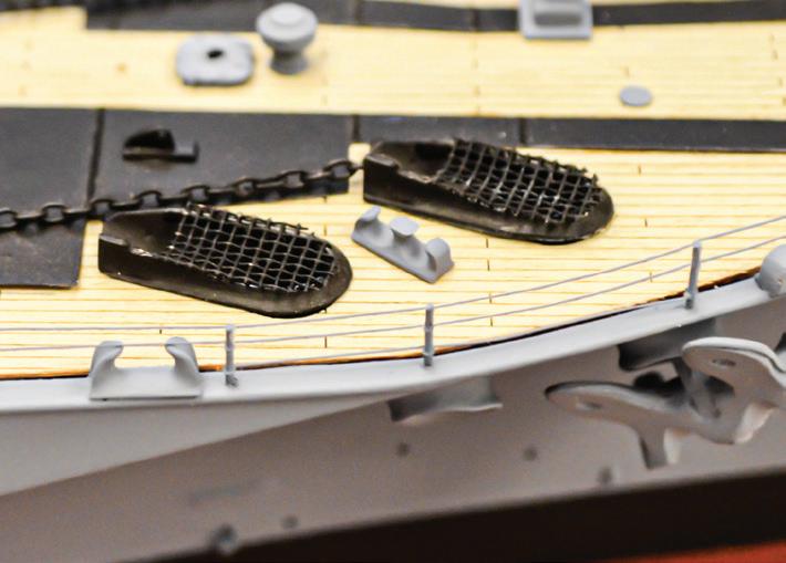
This Arizona model was one of an edition limited to one hundred thirty-nine finished units manufactured by Fine Arts Models of Marine City, Michigan, and released in 1995. In business since 1989, the company offers models of many transportation-related subjects: cars, ships, trains, aircraft, and military weaponry. At 1:192 scale, this piece was in the range considered by many to be a miniature ship model. However, at a length of 38 inches, it did not feel particularly small. Fine Arts Models indicates that they utilize a broad range of traditional and modern techniques and materials in their models.120
Although the work I did on Arizona took only a few minutes, I want to bring it to
your attention. It is the newest model presented in this book. I didn’t have the opportunity to analyze its complex construction, but the marriage of modern processes was visually seamless as far as I could tell.
The model had been cased, but somehow deckedge lifelines near the bow on the starboard side had been damaged. The client was a maritime museum that asked me to use conservatorially appropriate procedures. The lifelines appeared to be wire that had been soldered to rod stanchions. Everything was painted, so I didn’t know what kind of metal, solder, or paint was used. I didn’t want to test anything because the affected areas were all exposed. I certainly didn’t want to use heat to resolder the joints because it could have discolored or melted things. In making glue splices on fiber rigging, I’ve used fish glue to great advantage, but it dries brownish and would not look good, here, if excess glue was exposed. I’m a fan of B-72, but I’d always used it dissolved in a solvent. I learned that it is available in a tube like the plastic model cement I used (I admit it!) when I was a boy building kits.
I straightened the bent wire lifelines until they fit between the stanchions as they were intended, then touched each joint with a little B-72 on a pointed stick. B-72 dries rapidly, so my job was done quickly.
Since the edition that included this model of Arizona was released in the 1990s, Don Preul of the U.S. Naval Academy Museum has done considerable research for a model of Arizona he was commissioned to build for the USS Arizona Memorial Visitor Center at Pearl Harbor, Hawaii. It had been long and reasonably considered that most of the vessel’s exterior had been painted a uniform color. However, Preul learned that the tops of three of Arizona’s four main-battery turrets had been painted red so the ship could be identified from the air.121 It occurred to me to ask my client if they’d like to have the turret tops of this model painted red. But the museum decided that doing so would compromise the intent of the model’s original builders. So, they remain gray. ¯
136
The 1:192-scale, 38-inch model of Arizona
The damaged life rails. The straightened life rails.
oSeden was a tramp. She was built in 1918 by Blyth Shipbuilding & Dry Docks Co., Ltd., in Blyth, Northumberland, England. She was 363 feet long and 51 feet in breadth. Surviving the First World War, she typically carried sugar and traded between Java — in what was, before the Second World War, the Dutch East Indies, but is now Indonesia — and ports around the Mediterranean. In about 1936 she was sold and renamed Leo Dawson. In February 1940, while steaming toward England’s east coast with iron ore and no longer camouflaged, she was torpedoed by the German submarine U-37, and her entire crew perished.122
Roseden was an engaging 45-inch, 1:96-scale model. Her camouflage was strongly depicted and may be why the model was built, but the specific dazzle pattern was “probably from the imagination of the modeler.”123 The down-to-business visual effect of the camouflaged gray ship was, however, offset by the model’s enormous number of unpainted metallic fittings. While the camouflage spoke loudly for the model’s credibility, the bright brass provided countless interruptions.
Roseden’s scale was determined by measuring the draft marks at the bow. A look at the photograph will reveal why measuring them at the stern was impossible. The scale was confirmed by checking it against human-sized fittings like doors and life rails. Perhaps the smaller scale reflected restricted budgets for things as frivolous during the First World War as a model of a little freighter.
The model had been protected from normal damage by a case. But it was of little help against the flash from a gas explosion inside a building. The shards of the case’s shattered glass panes sliced through rigging and crushed other details. Worse, the flash turned one end of the case and the model’s stern into charcoal briquettes.
On this 1979 job, my task was to write an estimate for repairing the model, as forlorn as it looked. Honestly? I thought it was salvageable.
I developed an approximate strategy. First, I would determine how far forward the charring affected the wood substrate beneath the paint. This looked to be just aft of the superstructure. I’d do this with sandpaper and a scraper, which may sound harsh, but take another look at what I was working with. Next, I’d photograph and sketch the entire aft end of the model and remove and catalog all the fittings. (Memory boards were twenty-five years in my future.) I’d also transfer to a drawing the profile of the stern and sections of the hull at a few stations.
Case Study 24
Roseden
1918: British Merchant Steamer
Contemporary Rigged, Full-Hull, Builder’s Model
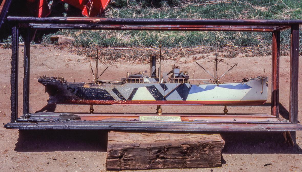
Then I’d amputate the stern. Material for a new stern would be prepared and temporarily joined to the model with two or three stout longitudinal pegs. The fair lines of the existing hull would be extended to the new block, then the block would be removed and carved to approximate shape using the sketches. When it was about right, the new stern would be fastened permanently and dressed to its final shape. Wooden deckhouses and other details would be prepared, then the new work would be painted. Everything would be dictated by the photos and sketches except the camouflage scheme, which would require reimagining.
Repairing the rest of the model would be time-consuming but average work. At the time, I imagined the baseboard and case were beyond hope. However, I now realize that a skilled furniture conservator could likely recover the loss.
In the end, the job did not happen. It would have been a marvelous challenge, but it boiled down to economics. My estimate exceeded the model’s insured value. However, all was not entirely lost; this was a model from which I was able to strip several hundred parts before it was sadly discarded. ¯
137
R
Roseden as first seen with her stern and case charred. The photo was taken outside the dark shed she where she was stored.
Case Study 25
Curacoa
1918: British Light Cruiser
Modern Rigged, Full-Hull Model
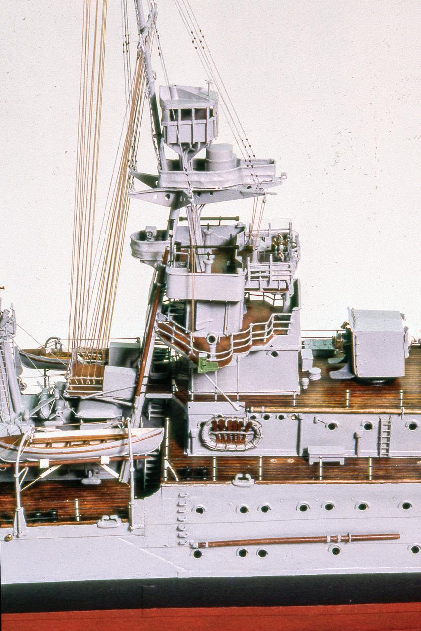
CuraCoa was one of five in the Ceres-group of C-class light cruisers ordered by Britain’s Royal Navy during the First World War. She was completed in 1918 at Pembroke Dockyard, in Wales. She was 450 feet 6 inches long and 43 feet 6 inches in beam. She displaced about 5,275 tons loaded. Initially configured for surface warfare, her main battery was five 6-inch, 50-caliber breech-loading guns in single mounts. She also carried two 3-inch high-angle guns, two 2-pounder pom-poms, and eight 21-inch torpedo tubes in four twin mounts. In late 1939 and early 1940, she was converted to an anti-aircraft cruiser, but those details aren’t part of this story.124
The ship was damaged by enemy action in both World Wars — a mine in the First and aerial bombing in the Second. Her fate, however, was at the hands of her friends. In October 1942, Curacoa fell victim to confusion during submarine evasion maneuvers and was rammed and sunk off Ireland by the huge, fast-moving, troop-laden Queen Mary, whom she was escorting. A closely kept secret, Curacoa’s loss was not reported to the public until after the close of the European war in May 1945.125
The Modelwright
Norman A. Ough (pronounce his name like the letter “O”) was a mid-twentieth-century English ship modeler. Like many other great modelers, he started early. A Londoner born in 1898, his interest dated to when he was “three and four,” and he began modeling “in earnest” while attending the Exeter School of Art. In his twenties, he “came into prominence” by modeling, for a 1925 exhibition at London’s Royal United Services Institution, a 1:1200-scale fleet of one hundred fifty-four vessels — every Royal Navy ship in the 1916 Battle of Jutland. The project took young Ough only ten months. For the same organization, he afterward built several 1:192-scale waterline models that were reviewed in the
journal Ships and Ship Models as “probably the most accurate and detailed ship models in existence.”126
These models moved on to London’s Imperial War Museum, a trustee of which, Francis Curzon, fifth Earl Howe, wrote Ough directly to say, “I have the greatest possible admiration for your work.” Curzon meant what he said because he commissioned Ough to build a 1:192-scale waterline model of the battleship HMS Queen Elizabeth for presentation to Sir David Beatty, who commanded the Royal Navy’s battlecruiser squadron at Jutland. Curzon had intended that Ough portray the ship as she appeared during the First World War, but Ough had depicted many details in peacetime colors to breathe more life into his work. This didn’t please Curzon, who wanted the portrait as drab as the ship had been in battle. Then Curzon ordered a second model for himself. To avoid problems with the second model, he specified that it represent Queen Elizabeth “as she was on the day of the surrender of the German Fleet, 25th November 1918.” The first model was delivered to Curzon after about only four months. For the second model, Ough charged two hundred pounds and later said he was paid two shillings an hour. The model, therefore, took him about two thousand hours. Even though he considered himself “rather on the fast side, as craftsmen go,” this seemed incredible because the model was delivered in early May 1931, slightly more than five months after it was ordered.127
Another of Ough’s noteworthy commissions was a waterline model at 1:192 of the D-class destroyer HMS Daring. This was for her commanding officer, Lord Louis Mountbatten, who wrote to Ough, “Your model has been much admired & is a masterpiece” — despite having some details to correct. Just a month before the outbreak of the Second World War in 1939, Mountbatten ordered a pair of smaller-scale models of his new command, the K-class destroyer HMS Kelly, one for himself and one “to be a gift for H.R.H. Princess Elizabeth.”128
138
The bridge structure on the rebuilt model of Curacoa. Note the contrast of metal and wood fittings and the speaker tubes leading from the enclosed lookout station down, along the forward leg of the tripod mast.
During the war, Ough helped build models and create special effects for the commercial motion picture industry. The Internet Movie Database lists him twice, but Ough’s recent biographer Alistair Roach credits him with more film work. By the early 1950s, Ough had reportedly built roughly four hundred models. Even if the big Jutland fleet is subtracted, the balance is about two hundred fifty models. If Ough worked consistently from age twenty to age sixty, that works out to about six models a year. I know of no professional ship modeler today who can work alone and approach that pace with Ough’s level of detailing. When asked why he never married, he “immediately” replied that he was “too much of a model maker” and “wouldn’t inflict [marriage] on any woman.” He died of cancer in 1965 with a couple of models still under construction.129
Ough shared his work with the modeling community. He displayed models at London’s annual Model Engineer Exhibition, but, like McNarry, was restricted from competitions because he was professional.130 He contributed often to many modeling magazines. Tracking publishing histories of periodicals of the 1930s and the Second World War is difficult, but it’s known that occasionally Ough had the same articles published in more than one periodical. Without doubt, the global ship modeling community would have benefited enormously if Ough had written a comprehensive book about modeling, but he never did.
During Ough’s career, the Royal Navy was not forthcoming with technical data concerning its vessels. This made research tough. Ough and his contemporaries had to work from information gathered by firsthand observation and photographs. Much of this was done during Navy Days, occasional weekends when Royal Navy dockyards and ships were more or less open to the public. Ough also conducted voluminous correspondence with the Admiralty.131
Fortunately, Ough recorded his research efforts in the form of plan sets for many vessels he mod-
eled. These were published during his lifetime. They were highly regarded and generated a modest income. Later, the plans were available in booklets and fullsize. Originals are now in the ship plans collection in the David MacGregor Library of the Brunel Institute, which is a part of the SS Great Britain in Bristol, England.132
Ough did not approve of the modeling style exemplified by highly finished and arguably simplified builders’ models. In contrast, he generally modeled in scales considerably smaller than the 1:48 standard for builders’ models. He covered his models with more and finer details. About high-gloss finishes, he wrote, “A model can be made or marred by the painting. Shiny paint is the ship model maker’s worst enemy, and it is astonishing how much work is spoilt every year by the use of it.” His painterly approach, smaller scales, clutterings of details, and muted finishes readily projected far more compelling impressions of real ships than did formal builders’ models. It is easy to look at an Ough model and believe that you are looking at a ship. Builders’ models were constructed in commercial studios with many employees. Although occasionally assisted in his work by another man,133 Ough worked, for the most part, secluded in a small room.
Ough built waterline and full-hull models. Most were static, but some, perhaps only two,134 were operable. One of these was built and rebuilt. This was Curacoa.
The Model
Ough evidently built two models of Curacoa. The first, a 1:192-scale waterline version, was likely made in the early 1930s, but it doesn’t concern us. We are focusing on a 1:96-scale Curacoa. It isn’t certain when Ough started it. In 1951, it was illustrated and appeared complete as a metal-hulled model in a brief article by G. W. Arthur-Brand. And John Fisher wrote that when he first met Ough at the 1952 Model Engineering Exhi-
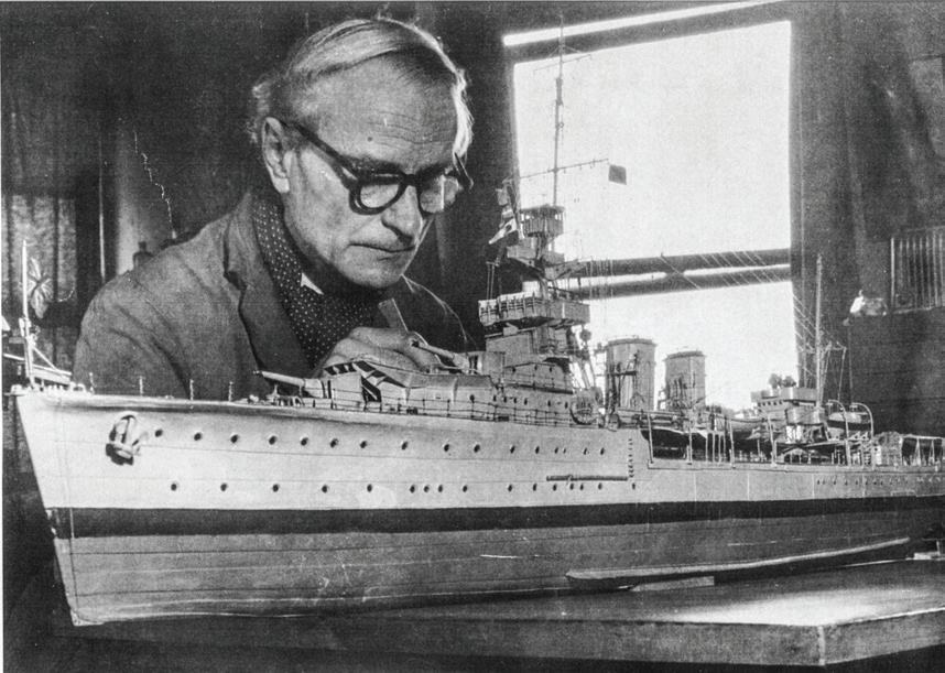
139
Ough with Curacoa. Strakes of shell plating are visible. (Photograph courtesy John Fisher)
bition, Ough had already exhibited “Curacoa in various incarnations at previous shows.”135
By the mid-1950s, Ough championed, and his writing dwelled on, the theory that operable warship models could be made of steel, like real warships. Further, he ardently opposed the conventional wisdom among modelers that hull shapes had to be altered to make models stable enough to be seaworthy. He described methods for building steel hulls; for calculating displacement, stability, ballast, and speed; and for fitting power plants.
This model of Curacoa was likely the first test platform for Ough’s beliefs, but it probably was not conceived with that in mind. For Ough, Curacoa may have always been a work in progress.
Some backstory is needed. Writing in 1955, Ough said that Curacoa was originally “made to satisfy a desire to have a boat to sail on the Round Pond in Kensington Gardens.” But he didn’t say when he initially acted on that desire. I suspected it was several years earlier, before the images with the metal hull appeared in Arthur-Brands’s 1951 article, because, Ough said, “the original hull was of wood with a tinplate superstructure and funnels, the plating being represented by brown paper strakes stuck on with shellac,” and that it had “twin screws driven by two electric motors.” It began to sound like Ough had built two operational models of Curacoa, a wooden one and a metal one. But he went on to say that, despite many coats of paint, the paper soaked off, and the hull leaked. To save the wooden hull, he cut it “horizontally just above the waterline” and rebuilt the portion above in tinplate. The hull still leaked, so he scrapped it entirely and built “the complete hull in tinplate.”136 To me, this sounded like entirely too much work.
With his all-metal hull, he evidently tried a new power source, as well. Perhaps he was rising to a higher challenge, or perhaps he found there was much more room to play with inside the newer, far more spacious metal model than there had been in the wooden one.
Regardless, a pair of miniature steam turbines built by Ough appeared in Arthur-Brand’s article. He reported that the turbines and a “flash-boiler” were for Curacoa. 137
There’s more. At roughly the time he was building the all-steel hull, Ough learned about radio control. Frustrated by the limitations of commercial products, he decided to build his own devices for “training and firing the guns, laying a smoke screen, controlling the engines for speed, either ahead or astern, switching on navigation and interior lights, and accurate steering.” This was quite a punch list by anyone’s standards. He wrote that, “After three years of spare time work,” he had “produced a mechanism that [gave] 31 controls.” He wrote prosaically about controlling the speed of “steam machinery” and romantically about “a model running with all lights on just after sunset while the detail [was] still visible, and the gleams from the port holes [reflected] from the wash along the sides.”138 A fine image! Unfortunately, though, Ough refrained from mentioning if any other features of his incredibly complex control system were completed or actually worked.
Also in 1955, British Pathé (a cinema newsreel service) recorded a two-minute silent film of Ough with Curacoa. In it, Ough works on a drawing, opens the model to show internal works in the metal hull, and loads a faux projectile into a gun’s breech. Also shown is a newspaper open to an article headlined “Five-ft model cruiser will have 30 ‘tricks’” and subheaded “Guns Fire by Remote Control.” The paper was not identifiable.139
The conclusion can be drawn that Ough’s work to animate Curacoa was on-going in 1955. But, because his schemes were presented in the future tense in both his own article and in the newspaper headline in the Pathé film, my guess is that beyond rudder and speed controls and lighting, his complete vision was not realized. Nonetheless, he wrote that his effort “succeeded” and “opened up a new field of model shipbuilding, to which it [was] impossible to assign limits.”140 In other words, he felt his cause was met.
140
When Curacoa came to my attention in 1989, there was clear evidence of a strong heat source in the form of black scorch marks and bubbled paint on the underside of the main deck and inside at least one deckhouse. These were certainly caused by something hotter than electric motors, so I believed the turbines and the boiler had been installed and operational. But the fire-breathing apparatus was gone. There was little evidence of any of the wires, mechanisms, platforms, battery boxes, or the like that filled the hull in the Pathé film. There was only a single, small electric motor. Bearing no marks of commercial manufacture, it appeared hand-made. It was not connected to the shafts and was associated with no gear except a disconnected switch.
Curacoa was plated with tinned steel strakes soft-soldered together. There were two principal decks. Installed permanently, the forecastle deck provided rigidity to the hull’s forward third. At the forecastle’s aft end, the sides stepped down to the main deck, which was removable and extended the remaining two-thirds of the length to the stern. Five transverse steel bulkheads provided hull rigidity under the main deck, but the deck was not attached to them. Decks were plywood with planking seams lined off in ink. Deckhouses were built-up of soft-soldered tinned steel. The structures were secured internally with metal tabs bent under the decks, like clothes on a paper doll. No fittings had operable features with the notable exception of the ship’s main battery of deck guns.
The model was in shambles. Paint was chipping, lifelines were mangled, and little rigging survived. Many components were loose on the decks. I determined their proper locations by analyzing empty holes, glue footprints, scraped paint, and other evidence. Ough didn’t restrict himself to a narrow palette when it came to media. On Curacoa, he used solid woods; plywood; plastic wood; steel, brass, and copper in sheets, rods,
tubes, and wire; paper; fabric; thread; card; celluloid; and, it seems, about anything else that came to hand. He employed only soft-soldering. He even sculpted fittings out of solder blobs. Each twin-tube torpedo mount was made of nearly sixty pieces of beech wood, plywood, brass, oaktag, paper, string, steel, brass, and copper. It’s no wonder they fell apart.
Through the mess, I saw that Curacoa was deliciously atmospheric, visually involving, and compelling. It was wonderful to examine closely and frequently. What a delight it was to discover speaking tubes veining down the mast from the lookout platform to the bridge! Ough’s techniques to produce visual texture depended on materials and their surfaces. James A. Powell wrote in Model Shipwright that Ough’s modeling approach combined with his building methods “to produce a model which was authentic in detail and… exuded ‘life’, something lacking in so many otherwise excellent models.”141 Curiously, though, taken individually and at close range, many components lacked refinement or consistency.
Overall, I had several positive initial impressions: Almost all parts seemed — amazingly — to be present; most components were built in such a way that fabricating replacements for losses would be relatively straightforward; and the model could be refinished to look crisp and uniform.
There were also questions: First, would an attempt be made to make the model operable again? No remnants of the original steam turbines or their gear survived. The extant electric motor didn’t work and gearing for connecting it to the propeller shafts was absent. The model was more fragile than it had been when it was new because of failed plating joints. So, henceforth, Curacoa would be a static model.
Second, how would opened plating seams in the hull be rejoined? Soft solder was appropriate because it had been Ough’s preference. For the large work, I acquired resistance soldering equipment; for small work, I relied on a regular soldering gun.
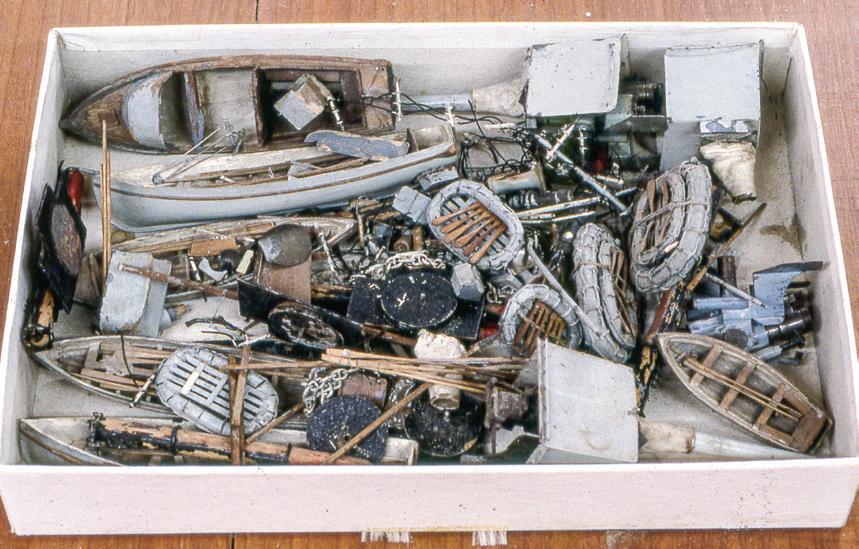

141 ¯
All these parts were found lying loose around Curacoa’s decks. There are 6-inch gun mounts; davits with falls; two twin torpedo tube mounts; six boats and five life rafts with oars and paddles; anchors with stud-link chain; gun directors; ladders; deck vents; and much more. The proper place was found for each item.
This tinplate deck house embraces the two funnels. It is shown upside down; forward is to the lower left. Six tabs (arrows) fold under the deck to secure the structure in place. Notice discolorations from the heat of powerplants.

Third, how much information was available about Curacoa? Of primary importance was a framed magazine cover with the model. It identified Ough and showed him with Curacoa. That was the Aha! moment because it positively tied Ough to the model. I obtained Ough’s published plans of Curacoa. The single 24- by 34-inch sheet delineated the profile, deck arrangements, and some deckhouse elevations at 1:192, half the model’s scale. Boats, weapons, and other systems were shown at the model’s scale of 1:96. There was no proper lines plan, but waterlines and a body plan were included. A note under the body plan read, “approximate only”142 and reflected that Ough developed hull shapes on his own, without benefit of Admiralty lines.
Three things immediately resolved in sharp focus: I had before me the work of a master modelwright, I had a once-in-a-lifetime opportunity to study his approach to modeling, and, at that moment, I became responsible for a portion of his considerable legacy. This challenge was not to be avoided!
Dimensional Instability
Years after finishing this job, I acquired copies of 1918era, 1:48-scale official Admiralty drawings of Curacoa that defined her as she had been built.143 They let me compare Ough’s work with original data.
Measured from the Admiralty drawing, Curacoa was 450 feet 6 inches long and 43 feet 6 inches in beam. In the legend on his published drawing, Ough stated the length as 460 feet and the beam as 43 feet 6 inches. Yet, measured on his drawing, the hull was 28⅝ inches long and 213/16 inches broad; these figures converted to 458 feet and 45 feet, respectively.144 The actual model was 58⅞ inches long and 513/16 inches in beam, which, at 1:96, converted to 471 feet and 46 feet 6 inches (see table above).
These figures were inconsistent, especially for length. As a self-proclaimed stickler who actively proselytized that operational models did not need to be larger than scale sizes to be stable in water, Ough’s increases in length by a scale 7½ feet on his drawing and 20½ feet on the model were disarming. More surprising still was that he built the model to be 13 scale feet longer than his own drawing dictated (or recorded). The 3/8-inch increase in beam on the model — or 3 feet on the ship — would have an even more significant effect on stability in an operational model than greater length.
Now, let’s compare the hull’s sections. In the illustration, black lines are from the Admiralty drawing. Red lines are from Ough’s drawing. For this overlay, the beam (but not the aspect ratio) of Ough’s body plan was adjusted to match the beam of the body plan on the Admiralty drawing. Then the heights of the deck amidships were aligned. Stations were at different fore-and-aft positions on each drawing, so they don’t coincide, but trends in shape are clear. If Ough really developed his lines just from dimensions, observation, and photos, he did a good job. He got the height-to-beam ratio just right. The sections coincide nicely in the sharply flared bow sections above the waterline and in the turn of the bilge amidships. However, Ough made the lower bow and the run — both below the waterline — quite a bit too full, and this gave his model still more than scale buoyancy. Was this accident or design? I suspect the answer is the former, but that it suited the latter.
In Ough’s defense, he was not working from Admiralty drawings. Nonetheless, the conclusion can be
142
Source Scale Measured Converts to Error Length Beam Length Beam Length Beam Admiralty Drawing Measured 1:48 112⅝" 21¾" 450'6" 43'6" 0 0 Ough's Drawing Stated 460'0" 43'6" + 9'6" 0 Measured 1:192 28⅝" 213/16" 458'0" 45'0" + 7'6" + 1' 6" Model Measured 1:96 58⅞" 513/16" 471'0" 46'6" + 20'6" + 3'0"
Ough with Curacoa on the cover of the December 1956 issue of the Dutch magazine Hand Bedeken

Superimposed tracings of the body plans from the Admiralty draft (in black) and from Ough’s plan (in red). Detail for locating the propeller and armor has been omitted from the Admiralty draft, but all the information from Ough’s drawing is present. The drawings have been adjusted to a common breadth. Notice that the Admiralty draft shows slight drag to the bottom of the hull, while Ough shows the bottom level.
drawn that he did not work out dimensions as well as he might have liked us to believe, and his own work did not agree with itself, at least here. But please make no mistake. No matter what shortcomings in Ough’s modeling are discernible from our vantage in time, “all twentieth century warship modelers are in his debt,” according to Philip Reed, another great British modeler.145
Admiralty drawings would be crucial for creating a new model. But it was key to realize that I wasn’t building a model, I was rebuilding a model. I didn’t have to listen to how Ough’s model should have been, I had to listen to how Ough’s model was. For this, Ough’s drawing and the model were really all I needed.
The Work
There were hundreds of subprojects within this job, but we’ll leave most aside in favor of five that were unique
to this model. These include resoldering the hull and testing its stability; reinforcing the main deck and relining its planking; cleaning and refitting the 6-inch guns; reinstalling the lifelines; and preparing the awning. Work on Curacoa consumed about three months and was completed in 2001.
A word on cleaning is in order. Vigorous application of the enzyme technique removed the grime on wooden decks and fittings. Metallic parts, especially inside the hull, were coated with a film of oil or the residue of soldering flux that couldn’t be wiped off. These were scrubbed away with detergent and a toothbrush until everything looked and felt clean. Today, the process would be streamlined with an ultrasonic cleaner. Where many parts came off the model, they left gobs of glue, paint, and solder. All would inhibit reconstruction, so they were chipped, scraped, filed, and carved away as necessary.
Plating
Curacoa’s plating was soldered together, and some seams had opened. The plates were made of tinned steel (or tinplate), a material Ough loved. It was available free from used tin cans or could be purchased inexpensively. Tinplate’s advantage is that it can be soft-soldered while plain steel can’t. At the time, I had extensive experience soft-soldering, but had never managed anything as extensive as a model’s entire hull. A small soldering gun wasn’t up to the job.
I had recently learned about resistance soldering. Heat is generated by passing an electrical current through the metal to be joined. This can be done on a large or local scale. I acquired a Hotip resistance soldering outfit from PBL, a firm popular with model railroaders.
Resistance soldering demands that surfaces be scrupulously clean, bright, and conductive. On Curacoa this meant removing old paint and solder. On exposed surfaces, this was easy with a wire brush mounted
143


The arrangement of components at the edge of the main deck. The three wooden components — deck beam (A), plywood deck (B), and rail (C) — and the outboard metal plate (D) are glued and pinned together to form the deck structure. The deck structure sits down, over the folded upper edge of the shell plate (E). The deck structure is secured to the shell plate only with one larger yellow pin (F) on each side. This pin is removable so the deck and the structures on it can be lifted off the hull.
in the flex shaft. Less accessible seam interiors were cleaned with thin ceramic cut-off wheels in the flex shaft.
To solder a seam, I brushed in liquid flux liberally, inserted bits of solder, pressed the seam closed from inboard and out with the soldering probes, and depressed the soldering system’s foot treadle to send current through the area. When the seam was tight, I filed or ground away excess solder and rinsed off the water-soluble flux. In all, I closed two seams in the bottom and two in the topsides. Voids in one seam could not be closed tightly; they drank a lot of solder.
Ough used plastic wood to fill gaps between the plates. In places, it had cracked. Water could enter the hull, but not directly. I sealed interior surfaces of the plastic wood with epoxy. Outboard, loose filler edges were lifted with a knife and the gaps were saturated with epoxy. Pushing the filler bits into place forced epoxy into problem areas.
To paint the waterline, the model’s draft needed to be determined, and the boy in me wanted to check the hull’s watertight integrity and stability. The model didn’t fit in the bathtub, and I wanted a more controlled environment than the town green’s duck pond. A tank was needed. I nailed together a frame of 2- by 4-inch stock on edge. Over the frame, a 2- by 10-foot sheet of polyethylene was draped and filled with water. Presto! Ough stated Curacoa’s draft as 16 feet 6 inches. I marked this at stem and stern with pieces of tape and lowered the model ceremoniously into the water. She looked wonderful and happy, floating high without ballast or superstructure. Then I shipped the two chunks of lead Ough used as ballast. The larger, at 3 pounds 8½ ounces, sat under the funnel casing. The smaller, at 15 ounces, fit between the propeller shafts. Now, the hull was stable because the ballast was low. When all the structural components and details were installed, the model floated about on its marks, but the center of gravity was much higher, and the model seemed mighty tender.
Floating the hull after so much work was gratifying. In half an hour, about a half-teaspoon of water had leaked in. I called that dry enough.
Decks
Curacoa’s main deck was 3/32-inch-thick plywood 38 inches long. It rested on a shelf folded inward along the top edge of the upper strake of shell plates. A vertical tinplate band was nailed to the deck’s edge. The band’s upper edge was flush with the wood, and its lower edge hung down, outboard of the hull. There were no mechanical connections between the deck and the hull so I added one long pin on each side for security.
The deck was pinned to five cambered, plywood deck beams. The pins had loosened, and the beams had split. Using an original beam as a camber template, I made five new basswood beams. They were sided about ½ inch and placed between deckhouse openings to assure full transverse support. I wire-brushed the paint off the deck’s underside to provide clean wood-towood surfaces for gluing.
Outboard of the deckhouse openings, Ough had thinned the deck’s underside, probably to make room for machinery. To starboard, the deck had split in this area for much of its length. The split’s edges pursed up-
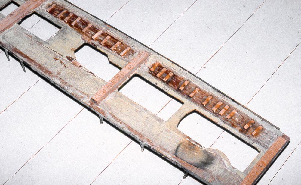
144
The underside of the main deck showing three of the five new deck beams (arrows) and twenty repair splines. Notice the heat discoloration.
The impromptu test tank.
Curacoa afloat in the tank. Basic structures are temporarily installed to see if the model floats on its lines.
A B C
D E F
ward conspicuously. I flattened and closed the split by epoxying twenty-two basswood splines across it on the underside.
The forecastle deck was also one piece of plywood, but it was screwed to a wooden beam shelf installed inside the shell plating’s upper edge. I replaced missing screws with similar copper, flat-head wood screws. Counterbores were filled with Lepage Polyfix. The edges where the forecastle met the hull plating were far from perfect, especially under the tightly rolled forward flare. Irregularities had been filled with plastic wood. This work likely dated from when Ough twice rebuilt the hull.146 I repaired the cracked filler as I had in the plating seams.
The wooden decks had cleaned up nicely but had lost their luster. To refinish them, Ough’s original ruled-ink planking had to be sacrificed. I did not relish this. After removing everything removable, I sanded the decks clean with 220-grit paper. The process left the surfaces with irregular colors. These were unified with Minwax special walnut stain that was sealed with two coats of Minwax clear satin polyurethane.
Ough’s deck seam ruling was erratic. It was neither equally spaced nor all parallel to the centerline. The deck edge was far from bilaterally symmetrical, port to starboard, and the train of midship deck structures wavered from the centerline by as much as ⅛ inch. Many seam lines were misaligned as if they’d been drawn in sections. Some planks were drawn carefully nibbed into margins; others ran out to feather edges. Some nibbing was concealed under deckhouses.
I’d hoped to trace Ough’s work, but it was mostly lost to the sandpaper. I started from scratch. It rubbed against my grain, but I followed Ough’s lead and ruled planks not parallel to the centerline. Chanting the mantra, “Do not upgrade the model,” I inked a few more planks to port than to starboard. Ough likely inked the decks without the impediment of attached fittings — chief among these being the permanently fixed forecastle breakwater. I didn’t have the same luxury.
Product directions always suggest testing a process inconspicuously. I chose the narrow athwartship area abaft the forecastle deckhouse on the forecastle. I sanded the urethane with 220-grit paper to give it a little tooth. Ough probably worked with a traditional ruling pen. I used a Pentel Ceramicron 500 II technical pen. The results were good. After ruling, I sealed the ink with an overcoat of urethane.
The 6-Inch Guns
The main battery of five 6-inch, 50-caliber guns was partially operable. They elevated and trained. They had spring-loaded recoil mechanisms, threaded breeches, removable tampions, and faux projectiles. There was no evidence of gear for remote manipulation or firing.
The guns were inconsistently rendered. Elevation racks, loading trays, and breech closures appeared on some but not others. I sought evidence that details were uniformly applied, and that some were just missing, but there were no telltale signs. Parts were made from brass and steel with no system. Two guns were missing their loading lights and brackets. There was evidence that they’d been fitted, so I made brass replacements.
To keep the guns workable, they had been oiled; a fine film covered everything. For cleaning, I disassembled the guns as much as possible and washed the parts. I polished the bright metal components with a buffing wheel in the flex shaft. To avoid having new oil negatively impact surrounding finishes, I did not relubricate the parts.
Brittle and cracked beyond salvation, the fabric blast bags required replacement. Each was a piece of fabric wrapped into a truncated cone. The larger, inner end fit the aperture in the gun shield. The smaller end rode around the barrel. Shield aperture sizes differed on each gun, so five individual paper patterns were needed. I cut each bag from cotton balloon cloth marketed by Boucher in the 1950s and 1960s. I folded a bag’s inboard end around a wire ring that I had shaped to match the

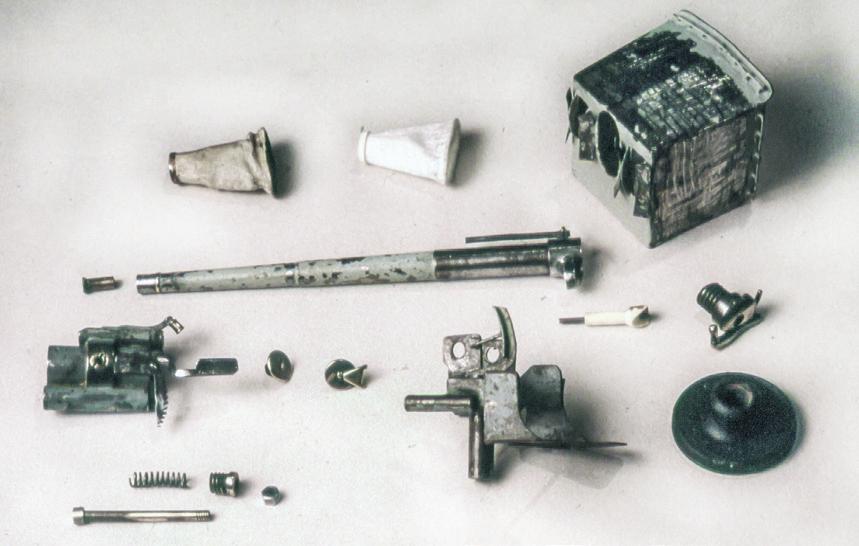
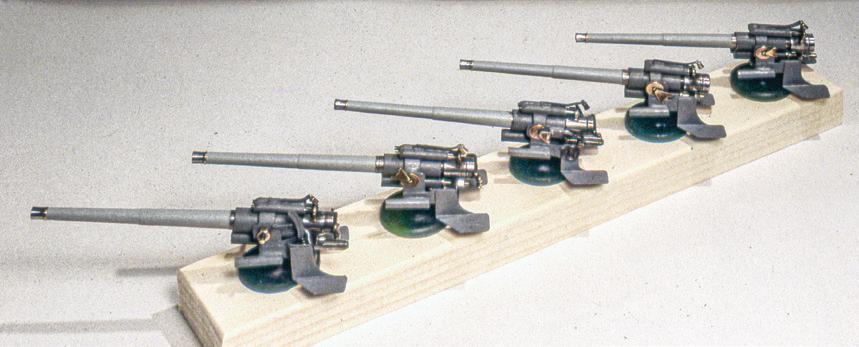
145
Sighting along the length of the hull from astern reveals considerable asymmetry.
One 6-inch gun disassembled. The projectile is the white item to the right of center. All parts are steel or brass except the fabric blast bags and the wooden circular mount. Paint has been stripped from the gun shield.
The five 6-inch guns rebuilt. Careful observation reveals that they are similar but not identical.
aperture and glued the ring inside the shield. At the outboard end, I wrapped a narrow paper band several turns over the fabric on the barrel and glued it to itself. When the glue set, the outer end maintained a circular shape that slid over the barrel easily.
Lifelines
Lifelines protected ten decks areas around the model. Here, especially, a capricious aspect of Ough’s workmanship prevailed. He built lifelines in five styles and three heights. Here are some examples: Some steel wire stanchions were either butt-soldered to the deck’s surface or into holes in the deck. Some stanchions were 0.025-inch soft steel wire soldered to a curtain plate. Some were made from common pins with their heads filed flat and soldered to the deck. Some penetrated the deck with pinheads below. Most stanchions were cut off square at their tops, as one might suspect. But many were common pins with their business ends sticking up unclipped, ready to bloody any handler. Stanchion spacing seemed erratic. On the model, it ranged from 4½ to 13½ scale feet. On Ough’s drawing, spacing was distinctly regular.
Lifelines are fragile and take beatings. Repairs are always fussy; these were no exception. I wanted to preserve as many stanchions as possible. For replacements, 0.025-inch brass rod was used. I risked angering the conservation gods by cutting all the tops square, without any blood-letting points. Where stanchions had been simply soldered to the top surface of a deck, I drilled holes so they’d have better seating.
The lower bridge lifelines had been severely compromised, especially to port, where the running light had been folded over and curtain plates had been torn away. Working with pliers of various shapes, I sculpted everything into alignment. I replaced two port-side rail segments and resoldered many joints.
Stanchions that framed gates, breaks in the lifelines, and corners were supported by angled brackets that Ough also formed in different ways. In some cases,
the stanchion and the bracket were formed from a single wire that was bent, staple-like, and inserted from the underside. The bracket part of the staple was simply bent inward and soldered to the stanchion. Other brackets were separate pieces seated in holes in the deck and soldered to the stanchions.
Where Ough used wire for rails, I replaced it with 0.012-inch brass rod because it resisted mistreatment. Working in situ, I soldered the rod to one stanchion, bent the rod to meet the next stanchion, soldered it there, and repeated. This worked more smoothly than I anticipated.
Ough used plain black thread for many life rails. I used linen. Like Ough, I secured it with overhand knots on the outboard faces of the stanchions.
The model’s sheer, particularly forward, was not particularly fair. Viewed obliquely, the foredeck edges were country roads of curves. This condition was likely a legacy of the model’s two rebuildings. Because the problem was integral with the bow’s structure, I left it alone. However, a visual ruse corrected things. Ough did not ensure his thread life rails were parallel to each other or to the deck, so I had room to work and still maintain his intent. When I rigged the rails, I installed the upper ones first. Instead of making them equidistant from the deck, I gave them a fair sheer. Then I spaced the middle and bottom rails evenly between the top rail and the deck at each stanchion. Now, when viewed obliquely, the foreshortening of the lifelines increases their visual power, and they help carry the eye away from the unfair deck edge.
The Awning
Along the main deck edge, from the stern to the aft deckhouse, there were sockets for tall, bracketed stanchions. About half survived; I replaced the missing ones with brass. Each had a hook at the top that matched in height a similar hook on the stern’s tripodal ensign staff. Also, along each edge of the flash shield on the
146
aft deckhouse, eight or nine short lugs stood upright. These were all for an awning.
Although there were no remnants of an awning, one was clearly present in a photo of Ough with Curacoa. I fit an awning to add another visual dimension and to preserve Ough’s documented intention. After finishing Curacoa, I found an article in which Ough described making an awning for a model.147 Unwittingly, I seemed to have followed his lead nicely.
For a ridge line, I stretched a 0.016-inch brass rod from the hook on the ensign tripod to the centerline lug on the flash shield. To make a pattern, I cut a piece of paper to the shape estimated for the awning’s starboard side and folded a tab about ⅛-inch wide along the centerline edge to drape over the ridge rod. I pressed the paper down to dimple it on the tops of the stanchions and lugs, marked off the dimple locations with pencil ticks toward the centerline, then trimmed the paper to just inside the dimples, leaving the pencil ticks.
The awning had a complex shape because it had two slopes — one from the ridge to the stanchions, the other from the flash shield to the stanchions. To relieve the resulting buckle, I cut the pattern to make a dart, as in clothing, then, with a needle, poked a hole at each tick for lacing the pattern to the stanchions and lugs. I repeated the process for the port side.
The long centerline tabs on the two patterns were glued together. To check that the whole awning could be made from one piece, the pattern was traced onto a new paper that was cut out and rigged. It fit.
Using a No. 4H pencil, the pattern was traced on a pre-starched and pre-ironed piece of the balloon cloth used for the blast bags. A 1/16-inch margin was added all around. I lightly scored the traced line, which was to be folded to create a hem, with a glass cutter; folded the margins under; and ironed them flat to form a hem that was snipped at each stanchion and lug to avoid wrinkles and to provide a slight gap for lacing. To reinforce the edges, 0.020-inch linen cord was glued in the
hem that mounted along the stanchions, and 0.020inch brass rod was glued in the hem that mounted along the blast shield. I used PVA glue and ironed the seams flat again. On a ship, awning stanchions were connected by a guy to which the awning was laced. On the model, a guy would strengthen the system. A long 0.016-inch rod was bent in the middle and soldered to the eye in the ensign tripod. Each end was then bent to extend in straight lines from stanchion to stanchion and was soldered to each.
Before installing the awning, I made sure everything that had to go on deck beneath it was in place. Then the awning was lashed to the stanchions and lugs with fine linen line. The fabric was colored in situ with a wash of equal parts water and Liquitex acrylic paint. ¯ Curacoa was among the most gratifying of all my complex model repair projects. The satisfaction of saving an important model from almost certain loss was amplified by two other factors. The first was the challenge of working in a medium, tinplate, that had been altogether foreign to me. The second was the pleasure of becoming acquainted with Norman Ough. ¯


147
The new fabric awning rides on a centerline ridgepole and is stretched between the blast shield and the guy wire along the awning stanchions.
Case Study 26
Helen Barnet Gring
1919: American Four-Masted Schooner
Modern Rigged, Full-Hull Model
I
n 1919, Robert L. Bean of Camden, Maine, launched the four-masted coasting schooner Helen Barnet Gring for Crowell and Thurlow, a shipping company in Boston, Massachusetts. She was registered in Portland, Maine. The 1,226-ton vessel measured 202.8 feet in length and 40.4 feet in breadth. She worked in the American East Coast and West Indies trades laden with cargoes of stone, lumber, and coal. She notably ran over and sank the stoneladen three-master William Booth in 1928. While sailing from Las Piedras, Puerto Rico, for Jacksonville, Florida, in 1940, Helen Barnet Gring was wrecked on the coast of Cuba at the age of twenty-one.148

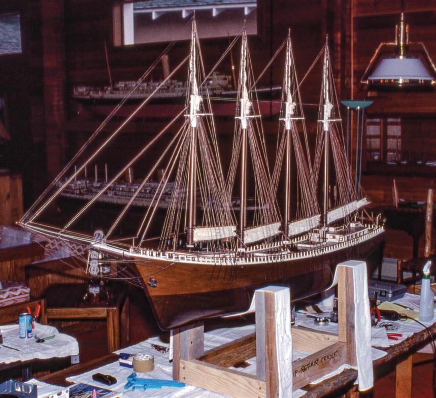
Almost certainly this model was built from plans drawn and published by Harold A. Underhill. A prolific mid-twentieth-century British ship modeler, he was noted in America for drawing modelers’ plans of nearly a hundred vessels, most of which were merchant ships. He was also well-known for a series of books about ships. His last work was the inspiring two-volume Plank-on-Frame Models and Scale Masting and Rigging. Underhill was always helpful with beginners. He once remarked that “it did not matter if a person was making something from a kit, plastic, wood or cardboard or whether he was making the thing right up from scratch. The important thing was that he was making something and was not relying on others to do it for him.” Underhill died in 1965 at sixty-eight.149
The three-sheet plan set for Helen Barnet Gring was drawn by Underhill, but he was quick to clarify that his work on American coasting schooners wouldn’t
have been possible without the unflagging aid of a Bostonian marine historian named Charles S. Morgan. The two exchanged voluminous correspondence about Helen Barnet Gring and other vessels just prior to the outbreak of the Second World War in Europe in 1939. Underhill wrote that Morgan sent him measurements down to “the thickness of stove pipes.” Underhill made drawings and submitted them to Morgan for vetting.150
A builder’s note found inside this plank-on-frame model said it was built at 1:48 scale (the same as Underhill’s plans) in 1981 by Leonard R. Currie, of Huntingdon, England, for Langfords Marine Antiques in London. For years, this gallery specialized in ship models and was operated by Lawrence Langford in association with his family’s principal business as dealers in fine antique silver.151
The model somehow seemed larger than it was. It was rigged with her four principal gaff sails. The gaffs were lowered, but peaked up slightly, with the sails bunted loosely between the gaffs and booms. I worked for a couple of decades with the collection that held this model. Not being cased, it received periodic cleanings. Exhibited high on a wall, it escaped harm and was in generally good condition. But something annoyed me — it never seemed comfortable or in repose. I finally realized it was because the four gaffs were not parallel to their booms. The sails looked just plain silly with their leeches flapping.
In a case of the exception proving the rule, I decided in 1995 to change how the original modeler had left the sails. The move was predicated on the fact that there were coils of line on the pins where the throat and peak halyards belayed, the coils were contiguous with the lines, and the coils hadn’t been glued to the pins. I cast off and overhauled the peak halyards enough to lower the gaffs so they paralleled the booms and tightened the gaskets that held the gaffs down. I felt a little guilty: I hope Mr. Currie will forgive me, but the model looks far more shipshape and comfortable. ¯
148
Helen Barnett Gring with her gaffs peaked up slightly.
The peak halyards have been slacked to make the gaffs and booms parallel. This was my first adjustable cradle.
The steel steamer Royal Scot was built and engined by the Caledon Shipbuilding & Engineering Co., Ltd., of Dundee, Scotland, in 1930. She registered 260.8 feet long, 38.3 feet in breadth, and 1,444 gross tons. Her single triple-expansion steam engine drove her at 12 knots. In June 1941, while steaming “from London to Feith with general cargo,” she struck a mine at the mouth of the Humber River on England’s east coast and quickly sank with her master and ten hands.152
Royal Scot was a strikingly colorful 68-inch 1:48-scale builder’s model of the most formal sort. The model produced a strong image of an upright and staunch little vessel. The hull was laminated from wooden lifts, and its considerable physical weight indicated that it was solid and had not been hollowed. Two symptoms of dehydration presented themselves. The first was that some lamination seams in the hull had opened and caused the paint covering them to crack visibly.
The second involved the cream-colored rail cap and cove beads that surrounded the hull’s otherwise black topsides. The beads were made of full-length, half-round brass bands that were pinned to the wooden hull. As the hull dehydrated over the years, its perimeter, around which the brass bands had been stretched, became shorter. But the dimensionally stable brass bands remained their original length. The result was that the bands had buckled away from the hull in many places and had, in so doing, pulled out many of the pins that secured them.
think the model had done all the dehydrating it was going to do. By then, the bands had already pulled away, but only slightly. To fix them then, I just pushed the pins back into their sockets. But the hull continued to shrink in its new and exceedingly arid environment. By a decade later, in the early 1990s, the problem had magnified to the state shown. A quick fix was no longer possible because distances between the pin holes in the hull had shrunk too much.
Case Study 27
Royal Scot
1930: British Merchant Steamer
Contemporary Rigged, Full-Hull, Builder’s Model
Refastening the brass bands by making all new holes in the bands and the hull was not a good idea because

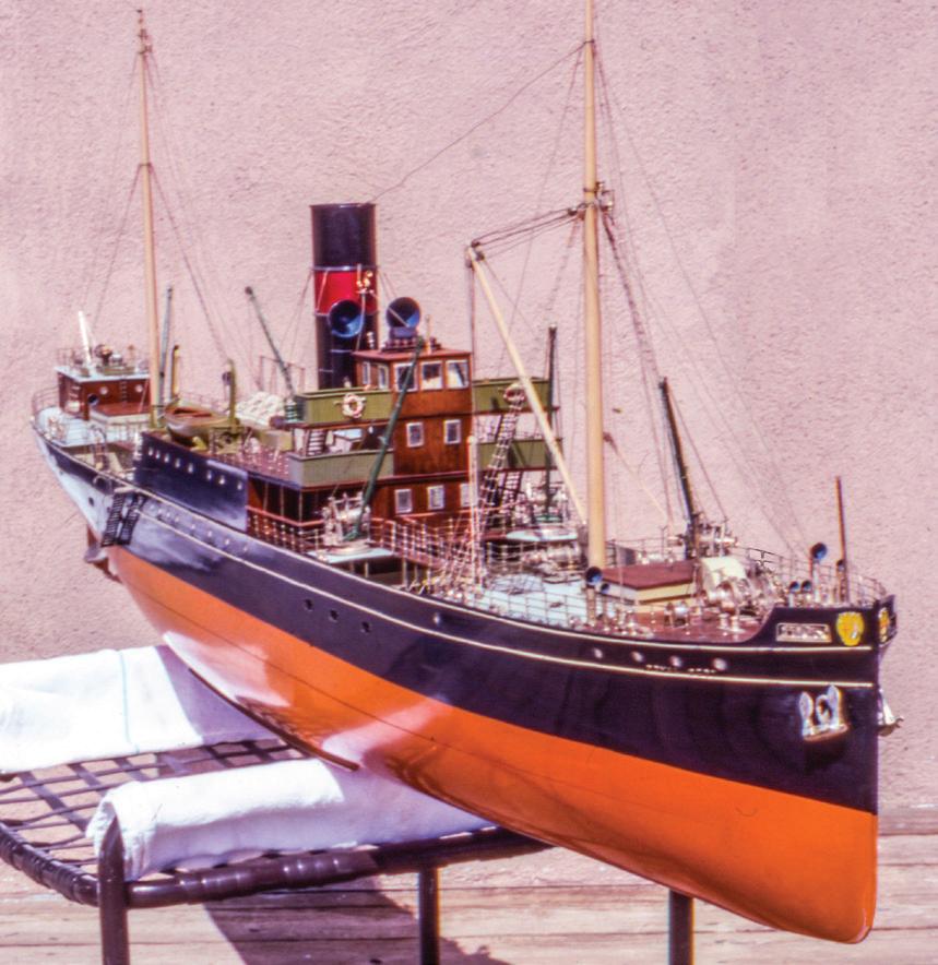
Bear in mind, that if the ship and model were built concurrently in 1930, by 1983, when I met the model, it was already fifty-three years old. One might reasonably
the results would be messy and would require considerable in-painting. When I noticed that the pins were irregularly spaced, the solution came to me. In 1992, I carefully removed each pin to release each full-length band — there were four, two on each side — from the hull. I flipped them end for end and secured each at the bow using the new forward pin. Pulling them aft and taut, I drilled new pilot holes for the pins in the wooden hull and drove the pins home. This elegant and simple mechanical solution worked. ¯
149
Above, left. The unattractively buckled cream-colored brass bands at the forward port waist of Royal Scot. The starboard side was similar. Notice the silvered deck machinery.
Above, right. The model finished. Notice the vermilion bottom that indicates Royal Scot was built of steel.
Case Study 28
Yare
1936: American Racing Sloop
Modern Decorative Half-Hull Model
The International One Design is a class of elegant and sophisticated 33-foot racing sloops designed in 1936 by a Norwegian named Bjarne Aas. The original fleet of twenty-five wooden boats was built in Fredrikstad, Norway, for use on Long Island Sound in New York.
Below,
Below, cwnter. The stickum under the tape is filled with dust and hairs.
Below, right. Using a No. 10 scalpel blade to lift the tape.
The class was conceived as a one-design extension of the popular 6-Meter class. The 6-Meters are an “open” or “development” class of the International Rule, which means that each boat is different, but the dimensions of each boat must conform to a particular formula. The best-known boats of International Rule are the 12-Meters that competed for America’s Cup from 1958 through 1987. Boats in development classes are relatively expensive for their size and make successful competition dependent on the skills of designers and pocketbooks of owners. The Internationals, said by British yachting authority Uffa Fox to have lines “as clean as a smelt’s and each and every line perfect for its purpose” represented “very closely the type of vessel we all hoped the 6-Meter rule would produce.”153 In effect, they let sailors compete in 6-Meter-like boats that pitted only the skills of the crews against one another in identical boats. Internationals are still being raced in about a dozen highly competitive fleets in North America and Europe. The boats are now built in fiberglass to match the specifications of the wooden boats in terms of weight and other factors.
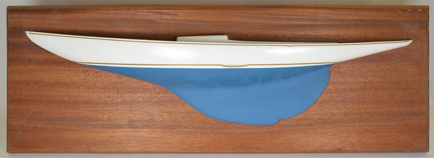
This model of Yare was one of a group commissioned for members of the International-class fleet at the Eastern Yacht Club in Marblehead, Massachusetts, in the early 1980s. The 24-inch, 1:16-scale half-model was made of molded fiberglass, which in this example was glass-reinforced polyester resin. The hull was molded white. The bottom was painted blue. The boottop and cove stripe are applied gold tape.
When it arrived in my shop in 2013, the boottop and cove stripe each drooped unattractively at one point along their lengths. The affected area on the boottop was perhaps 2 inches long, and the affected area of the cove was about ¾ inch long. It appeared that the tape had simply drooped. But if it drooped in those local areas, why didn’t it droop everywhere? There were no breaks in the tapes, so this meant they had stretched. I wondered if pressure had been applied against the tapes, perhaps during moving, or if there had been a local application of heat. Stickum residue was present on the hull along the tapes’ original paths.
What was the best way to fix the problem? The client casually suggested removing the tapes altogether and painting new stripes. This seemed like a good solution if for no other reason than that, if the boottop was repainted, it could be laid out properly. (The boottop tape had a constant width that was satisfactory enough along parts of the hull that were basically vertical. But, to appear to be the same height when viewed from abeam, the boottop must become much wider where it rounds the stern in the hull’s nearly flat run. Fixed-
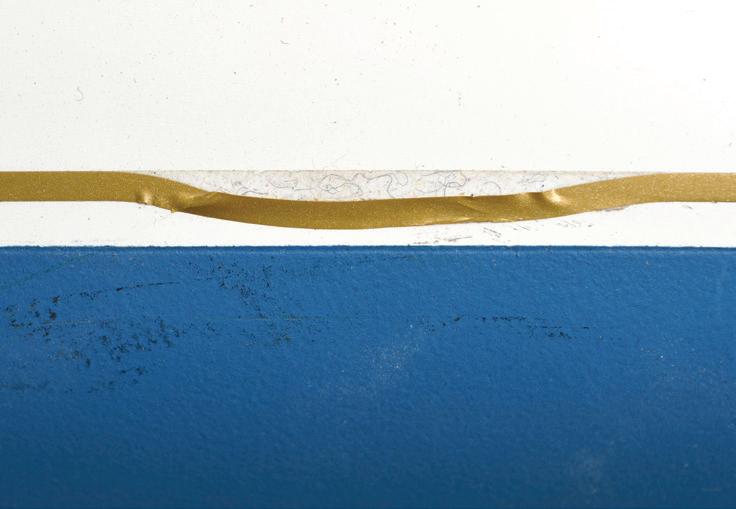

150
left. The half-model of Yare with droops in the tape cove stripe and boottop (arrows).
width tape won’t do that.) However, removing the tape and adding a painted boottop would change the nature of the model and would be a lot of fussy work.
The stickum was still slightly sticky. It likely had been part of the tape. But now, the stickum was part of the hull. In other words, the sticky part of the tape had stayed where it originally was, but the gold surface had separated from it and was now just a film. I don’t know what the film was made of. It seemed partially metallic and partially like vinyl: maybe Mylar. Short hairs, dust, and other nasty stuff was stuck in the exposed stickum where the tape had drooped away. I tweezed away as much of this foreign matter as I could.
Starting with the boottop only because it seemed stouter, I prodded the film with fine tweezers to learn if it was still flexible or if it was fixed in its droopiness. It moved, but it was fragile. I lifted it slightly with the tweezers, then I worked a scalpel with a No. 10 blade under the film to release its surface from the remaining stickum. I began at the center of the droop because this was farthest from the most tenacious stickum; resistance was less than at the ends. I stopped when I had released all the drooping film.
Cleaning away old stickum residue would have been easy — just scrape it off the hard surface of the model. But regluing the film with new adhesive could have been messy. Further, I wasn’t sure which glue to choose. Because the stickum was still slightly gooey, it occurred to me that it might still be viable.

The stretched film was now longer than the distance it had originally spanned. With care, and starting from the ends of the droop, I laid the film down along its proper course in the old stickum. The film was willing to move, but not to stay where it was put. I shaped the end of a small basswood stick into a wedge to use as a burnisher. With it, I pressed the film onto the stickum. I didn’t rub because I didn’t want to fracture the film. Firm pressing helped, but the film’s edges curled upward, and the film developed a bit of memory for its drooping state.
I wondered if the stickum could be reactivated? Maybe heat would help. With a hairdryer on its higher setting, the discharge was almost too hot to work under. But the stickum softened. With tweezers and the burnisher I worked the film back into its proper alignment under the direct heat. The heat made the fiberglass generate its characteristic aroma. When the film was in place, I burnished it firmly. The surface wasn’t quite as smooth as it was in undisturbed places, but, when the heat was withdrawn, the tape stayed put.
Because the film had stretched, there was a little bump at one point. To solve this, I cut the film near the bulge and lay one end over the other. Another cut through the overlap ensured that there was a perfect joint between the ends.
With the technique well-learned on the boottop, it was easy to do the same thing for the cove stripe. The repair was successful.¯
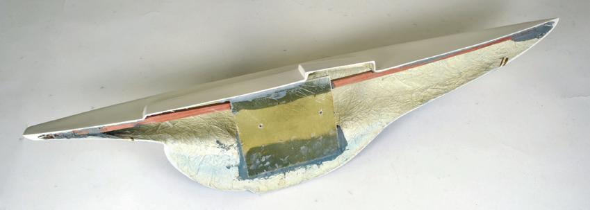

151
Far left. Softening the stickum with a hair dyer and burnishing the tape into the stickum with a basswood stick.
Left. The finished model.
A view of the back of the model of Yare shows that it was a simple fiberglass molding. The mahogany strip reinforced the deck. The yellowish plastic rectangle was epoxied in place to provide a surface for mounting screws.
Case Study 29
Ocean Pearl
1958: American Cruisng Ketch
Modern Decorative Half-Hull Model
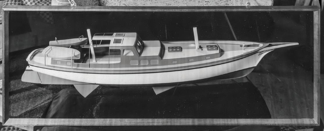
In the interest of full disclosure, I will reveal now that the opportunity to be associated with this project was particularly meaningful. It wasn’t because it was an evocative model of an interesting and comely vessel designed by a local celebrity for a wealthy patron, though it was all of those. It was because the vessel, its designer, and its place represented a target, a goal, an aspiration when I was impressionably young. Indulge me in this last chapter to tell you about this. When I first became aware of this model, in 1970, I was twenty-four, fresh out of the Navy, looking for a place to live, and figuring out what to do. I’d been directed, for a winter rental on Cape Cod, to the home of F. Spaulding Dunbar, a naval architect who had designed and built the 15foot sloops in which, a decade earlier, I had learned to sail and race. His cozy, dark-paneled living room was decorated with half-models of yachts he had designed and full-hull models of exotic Dutch fishing craft. Dunbar told me about the models, none with more pride than the one of his own pièce de résistance, the mellifluously named Ocean Pearl . Mounted on a framed mirror, the half-model was intended to look like an entire boat. Dunbar explained that this was “front-face” mirror, glass with the reflective surface on the forward side so there was no disconcerting visual gap between the model and its reflection. He said Ocean Pearl had been modeled by Donald Rosencrantz, whom he had met during the Second World War and for whom he had the highest regard. When the model was first completed, Dunbar said, it was a bit — the distance between his thumb and index finger implied an inch or so — too short. Rosencrantz retrieved the model, cut off the stern, made a new stern, married it to the rest of the model, and repainted everything seamlessly. “That’s how good Rosencrantz was,” Dunbar
said. That was his story. I took the rental, a windmill attached to his home.
Dunbar had built an excellent life for himself. He was educated in the naval architectural program at the Massachusetts Institute of Technology in the 1920s. He spent six months aboard an Isthmian Line steamship, rising from oiler to second assistant engineer during a passage around the world. He then shipped aboard Coriolanus, a Scottish-built, iron, full-rigged ship built in 1876 that had traded to the East but was, by Dunbar’s time, serving as a packet bark between New England and the Cape Verde Islands. During the 1930s, he settled in Chatham, on Cape Cod, organized a boatyard, and started designing and building small one-design sloops. The Second World War found Dunbar becoming vested in powerboats when he took a job with Elco (Electric Launch Company) in Bayonne, New Jersey. There, he worked on PT boats for the Navy,154 and it was there he met and worked with Rosencrantz. As a result of his time with the PT, boats Dunbar developed, after the war, a line of small derivative power boats, the Bristols, that became widely popular. His greatest achievement, though, was in the field of midsized sailing yachts that were conceived for the unlikely combination of blue-water passage-making and shallow-water cruising.
The queen of this fleet was Ocean Pearl. She was a 62-foot, twin-engine, double-headsail ketch. Her most remarkable feature couldn’t be seen. She had tandem centerboards, meaning one was abaft the other. (Twin boards are side by side.) The combination of the twomasted rig and tandem boards permitted perfect balance under any sailing conditions. The midship cockpit divided the accommodations below. The owner’s spaces were amidships and forward, the crew’s space was in a separate cabin way aft. By all accounts, the vessel was a success. Built in 1958, I’d been aware of the yacht since I was about twelve. When she entered or left her slip in Chatham’s Stage Harbor, people paused to watch. As of this writing (in 2015), Ocean Pearl has had a recent
152
Ocean Pearl on her original front-face mirror backboard. Vertical striations are artifacts of inadequate washing of the original black-and-white print. (Photograph by The Kelsey Studio, Chatham, Massachusetts)
complete overhaul and is still actively sailing, although not with her original owners.155
Simply put, Dunbar was a mentor to me. More specifically, he gave me several perfectly timed opportunities through the mid-1970s. The first came during the fall of 1970 when I expressed a general interest in building a small wooden boat for recreational rowing. Dunbar told me I must visit a certain fellow in Essex, Connecticut, and tell him what I sought. He said the fellow would have a design he’d share without reservation because he’d already have something better in mind for himself.
The fellow was Rosencrantz. In recollection, his workshop occupied a building tucked under trees behind his home; the room seemed large. Narrow aisles separated many work surfaces that were covered with projects. There was little open horizontal area. At the time, he was about sixty years old (he died in 1981 at seventy-one). Known as one of the “premier model makers in America,” he had also built a couple of rowing sculls and was a master cabinet maker. There are four of his models in the Smithsonian Institution and two at Mystic Seaport Museum.156
As Dunbar predicted, Rosencrantz gave me a design, but it was not on paper. It was offered as a 1:8-scale, pine half-model for a slender, hard-chine, sweetsheered rowing boat about 17 feet long. If I wanted the boat, I’d have to take the lines off the model, design the construction, and do the building: just like in the old days. Dunbar and Rosencrantz were sending me to school, but I had no classroom.
As it happened, Dunbar by that time had long since rented his boatyard to another man who operated it. Now that man was moving on, and Dunbar, needing a new tenant, asked if I’d be interested in running the yard. So, at twenty-five and with no experience in business or small boat maintenance whatsoever, I accepted Dunbar’s second opportunity, formed a partnership with a friend, and was off. We cared for small local working and pleasure boats; a 30-footer was large for
the facility. When everything was tucked away for that first winter, it was time to build Rosencrantz’s rowing boat. Then, the next year, Dunbar designed (this time on paper) an 18-foot sailing skiff for me to build for a client.
The fact was, I loved the intellectual process of boatbuilding, but boatbuilding didn’t grab me. I found the work was — well — at the wrong scale. Yet I realized model building offered the same intellectual challenges at scales that appealed to me and that I accepted easily. Leaving the boatyard and the operation of it to my partner, I muddled about for a while, then, in 1973, decided that I would do whatever was necessary to make ship modeling my career. I don’t believe Dunbar was surprised. He’d watched me refinish and rerig a couple of models and knew where my heart was. The third opportunity he offered was to steer some important early model work my way.
Somehow, about thirty years passed. I had long since left the Cape in favor of Newburyport, Massachusetts, but my wife Sherry and I frequently returned for Thanksgiving. In about 2005, at the home of friends, we met a fellow named Alan McClennen who asked if I’d like to see something in his car. He brought in a large, battered cardboard box. To my astonishment (but probably not yours, by now) it contained Rosencrantz’s half-model of Dunbar’s Ocean Pearl.
McClennen was a life-long friend of Dunbar’s son Bart. At some point, perhaps more than a decade earlier, the model had been, McClennen said, “mishandled.” Bart (Spaulding had died in 1991 at age eightfive157) had turned the model over to McClennen for repairs, but as so often happens with projects like this, he never got to it, and McClennen asked if I thought it could be saved.
The Model
The model was in terrible condition. Parts of the pilothouse were broken. The paint was suffering dreadfully.
153

The model before disassembly.
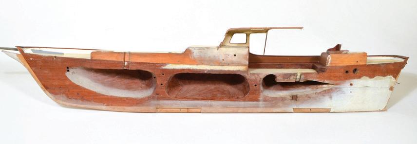
The back of the model showing construction and hollowing to reduce weight. At the bow, the mahogany hull block, which is dark, is distinguishable from the pine stem, which is lighter. While the outer, molded face of the stem presents a clipper-shaped bow, the stem rabbet, which is the forward end of the hull’s molded shape, is a straight line. This made the hull easier to plank, but also means the vessel did not, technically, have a clipper bow. No indication of Rosencrantz’s “correction” is visible.
The topsides have been rubbed down to remove most of the nicotine residue, but the shadow of the eagle and scroll on the transom indicate the severe extent of yellowing. Notice the discoloration from rusted fastenings in the bare wood at the top of the stern

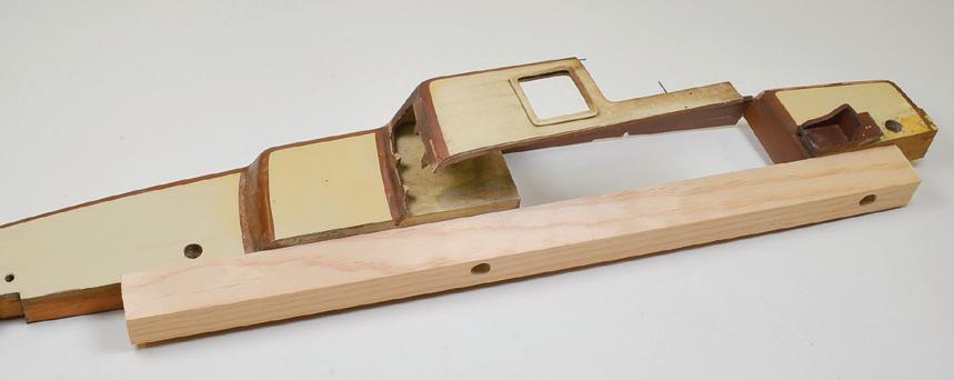
The coaming joining the two trunk cabins was built to scale, but too flimsy to withstand upcoming work. To eliminate stress, to keep them in their relative positions, and to provide a means of holding the structure in a vise, a pine block was screwed to the back. Existing holes in the original parts were used for the screws.
In addition to normal dust and grime that had settled on upper surfaces, everything was coated with, and the white topsides were especially yellowed by, nicotine from the Camels Dunbar had smoked. The good news was that few, if any, parts were missing. Many had come adrift, but fortunately McClennen had tucked them into an envelope. The front-face mirror backboard had long since shattered and been discarded. Its frame survived, although its mitered and splined corners had separated.
The 1:24-scale model’s hull was made of one or possibly two mahogany lifts. It had been hollowed with three cavities to reduce the volume of wood that could distort with climatic changes and the weight that would hang on the glass. I examined the back of the hull closely, but never found any indication whatsoever of the alteration — the new stern — that Dunbar famously credited to Rosencrantz! Rosencrantz had made an entirely new model!
The two principal trunk cabin blocks and the thin coaming connecting them were pine. The coaming was pierced for ports that were represented with clear plastic inserts. An open pilothouse with plastic windows surmounted the forward trunk cabin, and various other fittings, both custom-made and store-bought, were applied. The deckhouse assembly was painted brown and yellow. The yellow paint was sound, but the brown was peeling and cracking away from the wooden substrate.
The cleaning process began in 2013 with a no-nonsense brushing to remove loose dust and grime. The enzyme technique was applied. On Ocean Pearl it had little effect. I don’t know if this was because the paint Rosencrantz used was particularly susceptible to the tobacco smoke or if it was because the model was exposed to lots of it, or both. I tried weak detergent solutions, then more abrasive cleansers; all failed. Even steel wool did not cut through the yellowing. In the end, I realized that the hull’s original finish could not be saved if it was to present as white. I considered sanding things only until they seemed smooth and clean
enough to repaint. But visions of residual discoloration or any of its evil friends bleeding through new paint haunted me. It finally became clear that the model required complete repainting.
To facilitate sanding, I disassembled the model. All the fittings, including the trailboard, bowsprit, stern scroll, and eagle, were removed. The deckhouse assembly was taken off the hull by removing two wood screws that were hidden under deck fittings. With the two trunk cabin blocks connected only by the thin coaming, the assembly was flimsy, so a large wooden block was screwed to the back. This made it possible to secure the assembly in a vise. All the model’s surfaces were then sanded with 220-grit paper to the point that no original paint surface with smoke discoloration remained and all edges where paint had peeled and chipped were feathered smooth. Where paint was checked, but not flaking, I filled and smoothed inconsistencies with Lepage Polyfix.
Repairs
Three repair projects should be mentioned before continuing with the refinishing process. The first was to replace both stiles that had broken out of the pilothouse’s forward face. The structure’s face was a single panel of beech. Window openings were rabbeted inboard for plastic glazing, so it was easiest to rebuild each stile as two pieces. After cleaning up the broken edges, wood was removed inside, from the remains of the old stiles, to the depth of the rabbet. Then lengths of basswood were installed on those surfaces. These provided foundations for the outer pieces, the parts visible from outboard. The outer pieces were made purposefully too wide so they could be carved to final shape after installation.
The second repair involved the glazing, both for the pilothouse windows, which were thin and clear, and for the smaller trunk cabins and skylights, which were thicker and painted on their inner surfaces to be opaque.
154
I couldn’t identify the exact material Rosencrantz used for these parts, but they were some sort of clear plastic. To make the pilothouse windows, I made a template for each opening by tracing it on oaktag, then adding a margin sufficient to fill the rabbet. Then, with a needle, I traced the patterns onto new 0.020-inch-thick clear styrene that could be cut with scissors.
The plastic trunk cabin and skylight ports were painted aqua on their inboard surfaces. The adhesive used to retain the pieces in their openings had crazed the plastic. I couldn’t figure out how to resurface them to look good, so new glazing was required. The new material was 0.060-inch-thick acrylic made for framing pictures. I used extant pieces for some patterns and made oaktag patterns otherwise. I scribed the shapes onto the acrylic with the needle, cut them out with a 0.007-inch blade in the jeweler’s saw, and dressed them with a 00-cut file. To match the aqua color, I added cerulean blue to titanium white, then swirled in a little permanent green. This got me close to the aqua, and required then only fine tuning with the green and blue. Before painting, I roughened the inside surfaces of the panes with 120-grit paper to provide tooth for the paint.
After they were shaped, but before they were painted and installed, the sixteen new styrene and acrylic parts were washed in soap and water. Final installation was after the rest of the model was painted. Overall, the process of making the ports was easier than I had anticipated. Nonetheless, I was glad not to be making ports for RMS Queen Mary.
The third repair was to the rudder. It had been pinned to the sternpost, but not to the glass backboard. Being thin, the rudder had curled, so it no longer lay flat. Now, it was easy to think it had warped. But it hadn’t. A common problem of some lacquer and enamel finishes is that they shrink. If well applied to a properly primed side of a thin piece of wood, like Ocean Pearl’s rudder, paint can grip the wood firmly enough to bend it over time. That is what happened here. We don’t see rudders, centerboards and thin keels pulled out of shape on full-

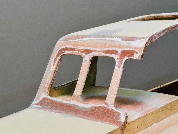
hull models because they are equally finished on both sides. If Rosencrantz had done that, the rudder would have likely stayed flat. You might ask why Ocean Pearl’s tandem centerboards hadn’t curled also. They were aluminum.
On a half-model with a non-reflective backboard, the slightly curled rudder may not have been objectionable. But on the mirror, it would look like parted butterfly wings. In the past, I had used steam successfully to flatten warped wooden items, but that couldn’t work here because the problem wasn’t with the wood. I thought about making a new rudder, but Rosencrantz had embellished this one with two sweet little carved scrolls that required preservation.
The rudder was about 3/32 inch thick along its thicker forward edge and tapered to slightly more than 1/32 inch aft. To preserve all the rudder’s original finish and details, I decided to remove most of the wood from behind the finish. I’d recently discarded some 1/32-inchthick model aircraft plywood. Ironically, it may have been the act of tossing it out that brought it to mind. Fortunately, the kindling box hadn’t been dumped, yet, so I retrieved the ply. I set the Preac saw to cut 1/32 inch deep and passed the rudder repeatedly over the saw to form a wide and shallow trough in its back. Near the aft edge, barely enough wood remained to maintain the original painted surface. A graving panel was cut from the ply to fit the trough. The plywood was a bit warped, so the graving piece was set so its warp countered the rudder’s curl. The graving piece was installed with PVA glue, and the rudder was clamped between two flat sur-
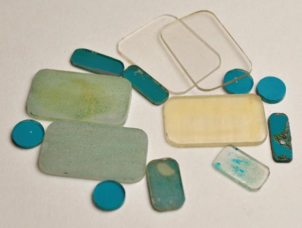
Above, far left. The inner portions of the pilot house window partitions are being installed and clamped with clothespins.
Above, center. The outer portions of the partitions have been installed and carved to shape.
Above, right. The plastic panels from the ports and windows were all replaced.


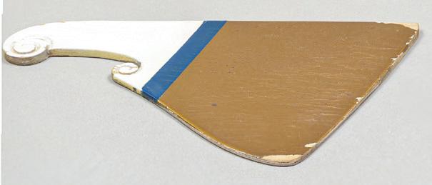
155
a panel of model aircraft plywood.
The plywood has been dressed to the rudder’s shape. The entire presentation surface of the rudder is original.
faces. Later, I trimmed the graving piece’s ends to fit, the rudder was flat, and the graving piece was barely visible along the trailing edge.

Masking and Painting
Now, back to the finishing process. The timid may want to stop reading. Most of the new finish was rebuilt with Rust-Oleum satin-finish products sprayed from the cans. The secret to these is to be conservative in the amounts applied in each coat and to sand lightly between coats. I started with white primer on everything. When surfaces were fair and smooth, I advanced to colors, proper ones of which, fortunately, were to be found in the regular Rust-Oleum line.

Half of the pencil lead has been filed away to a chisel-like point for more accurately marking waterlines on surfaces with changing curves. This is Ocean Pearl’s boat.
The second secret to spray painting is masking, and Ocean Pearl required a good deal of it. Some lines that had to be cut were already defined by their shape, like the blue rubbing paunch. Other lines, like the waterline and boottop, had to be struck before masking.
Striking the waterline and boottop is a fussy business. It’s best to use a solid jig. On mine, the model’s hull is screwed to a board that is perpendicular to the surface of a workbench. One of the screw holes in the board is too large so the model can be rotated slightly to get it exactly horizontal, fore and aft, before tightening the screw. The model is mounted bottom-up so the stern is easier to see. A pencil is clamped in a stand that can be adjusted for height and angle of its attack toward the hull. The pencil is set so it is perpendicular to as much of its course along the hull as possible. I use a standard Ticonderoga No. 2 sharpened to a fine point. Then about half the lead is sanded away so the point is semi-conical with the flat part downward. The tabletop must be smooth so the stand can slide without stumbling. The pencil is not dragged along the hull. Rather, it is moved along with the point kissing the hull here and there, just enough to leave fine ticks —
a sparsely dashed line. The idea is to not let the lead incise the paint. If that happens, and the line is in the wrong place, another corrective coat of paint may be necessary. The trickiest part is at the stern where the hull’s run flattens out and the pencil wants to skid off its horizontal course. That’s when the flattened point pays off.
After striking the line, I masked it. I learned this technique from the late Allen L. Baker of the Ship Model Shop in Eastham, Massachusetts, in the 1970s and have never found a better way. I wash and dry a large piece of ¼-inch plate glass so there is no dust or grease on it. Scotch Magic Transparent Tape masks an extremely fine line because it is thin and leaves only the tiniest paint ridge compared to regular painter’s tape. Lay a strip of tape longer than the model on the glass and rub it down gently so there are no bubbles. Wash and dry a straightedge, lay it on the tape, and, with a new No. 11 blade, cut away one side of the tape. This creates a straight baseline and eliminates any trace of the annoying dust or hair that collects on the sticky sides of a roll of tape. Cut the strip of tape used for masking next. For general masking, it isn’t necessary to measure a specific width. However, it is useful to keep in mind the following: The wider the tape is, the easier it will follow a fair line, but the harder it is to make it conform to tighter curves. And vice-versa: narrower tape follows tighter curves. If a portion of the line to be masked follows a gentle curve, like a waterline amidships, but has stronger curves at the ends, it is occasionally useful to cut the tape strip so it is wider in the middle of the length and tapers toward the ends. This idea was adapted from L. Francis Herreshoff’s concept of making tapered splines for drawing tightening curves on a vessel’s lines drawing.158 Experimentation dictates the widths that will work best on a given hull. Remember that this strip of tape is just being used to cut the line, not to cover area. Next, peel the tape off the glass. Do not let the end pop up and curl back to stick on itself or you will have
156
The hull is mounted on a bracket (A) that holds the hull’s centerline plane perfectly perpendicular to the horizontal drawing surface (B). The pencil is mounted in an adjustable device (C) that slides on the surface easily. Here, the line is about to be drawn for the top of the metallic bronze bottom paint.
A B
C
to restart. With an end of the tape in each hand, lay the tape’s center on the hull near the middle. Lay one end down without regard to accuracy. Lay the other end along the pencil marks, patting it gently with a fingertip along the penciled marks. Check the line’s fairness continually by eye from the ends and other vantages. It may help to do this with raking light that will allow the tape’s business edge to cast a visible shadow. It’s only important to pay attention to this edge, the other edge is unimportant. If an unfairness is seen, lift the tape off and re-lay it using muscle memory to help make corrections. When the line is good at the first end, lift the tape’s other end and lay it accurately. When a line is taped where I think it ought to be, I check the morning’s e-mails or get a coffee. On return, my eyes will be refreshed, and irregularities will stand out. After adjustments, burnish the tape to the surface to remove all the air pockets along the painting line. I burnish with the flat of my fingernail, but a smooth stick does nicely, too. This is when the tape becomes nearly transparent.
The rest of the masking is routine. Being sure to leave the newly masked edge in the clear, lay a length of regular painter’s tape over the Magic Transparent Tape and onto the part of the hull that must be shielded. If painting with a brush, the masking is complete. If spraying, I use plain white copy paper to shroud the model. Sprayed paint seems to find every opening, so it’s important to assure that every gap in the paper is sealed. A little blue painter’s tape is far less expensive than the time it will take to remove spray that has leaked through the masking. Whether brushing or spraying, apply the paint across the masked edge from the masked side toward the side to be painted. This minimizes the ridge of paint that collects along the masked line. It also helps to prevent paint from seeping under the tape and ruining the job.
Remove all the masking in the reverse order of application. Tape should be removed by pulling it acutely back on itself and slightly away from the masked edge. This will reduce its tendency to tear or to lift the paint.
Three problems may be associated with Magic Transparent Tape. First, it has no stretchability built into it like regular masking tape with all its little seersucker-like wrinkles. It will not stretch easily around outside curves. It may be necessary to plan the painting sequence so tape can be laid on the inner or concave sides of curves. For waterlines on regular hulls, this generally means applying the bottom colors first and working upward. Second, some paints may soften the tape so it is difficult to peel off without tearing. If this is the case, remove the tape as soon as possible, even if the paint isn’t set. Third, the tape really is transparent after burnishing, so care must be taken to keep track of where it is on a model.
Initially, I thought it would be possible to save Ocean Pearl’s original painted scroll on the trailboard. When it became clear the entire topsides required repainting, the scroll had to be sacrificed. To get it right later, I photographed the scroll as square-on to its surface as possible. In Photoshop, I adjusted the image to match its size on the model. I made a print to use as a template. With a soft lead pencil that could be erased, I drew the vining’s central stem on the repainted trailboard. Then I added the volutes. I used artist’s acrylic iridescent bronze thinned about 15 percent with retardant. Otherwise, the tiny amounts of paint would set too quickly to work on the pallet, on the model, and in the No. 0000 Scepter Gold II brush. The trick for my jittery hand was to avoid trying to paint the full width of a line with a single stroke. Rather, I sketched a line in lightly with the paint. This permitted making corrections by thickening lines to either side as I worked. It’s much better to be light-handed for this operation; I wait until I feel just right.
The Backboard
Ocean Pearl’s backboard was clever and elegant. A large rectangular mirror was contained in a wooden frame. Two hand-sawed brass straps screwed to the back of
157

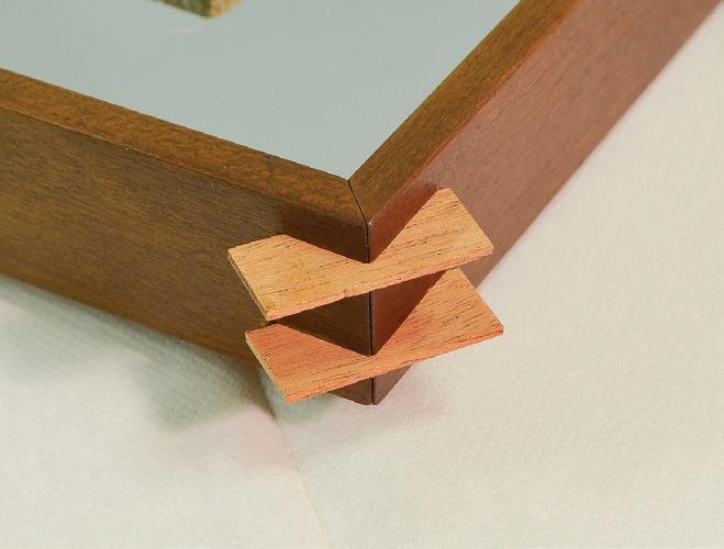

the frame’s horizontal rails transferred the weight of the glass and the model from the bottom rail to the wall upon which the whole thing hung. The model was mounted on the mirror with a pair of wood screws. There was no protection for the mirror’s surfaces. When the project came to me, the mirror was gone, but the four segments of the frame, the brass straps, and the wood screws were present.
The repair began by laying out the frame segments and measuring the maximum possible size of the glass that could fit into the frame’s rabbets. On tracing paper on a traditional drawing board, I constructed a rectangle just slightly smaller than the maximum size — I didn’t want any surprises of the “It doesn’t fit!” variety later. The model was placed on the paper and adjusted until its location seemed right. The bottom of the boottop was horizontal and the body of the hull was centered. This meant the bowsprit extended into the open area to the right. Then I traced the hull’s shape on the paper. The original screw holes in the back of the model were to be used for mounting. I measured carefully their locations on the model and plotted them on the pattern. DBI Glass and Aluminum in Raymond, New Hampshire, provided the mirror. It was not the same “front-face” product that Dunbar had celebrated years before. The best we could find was the same material that is used for one-way glass in observation rooms. The glass was ¼ inch thick and the screw holes were bored by the supplier with a diamond cutter.
Each of the mahogany frame’s four mitered corners had been reinforced with a pair of mahogany splines. Inexplicably, the splines’ grain had been parallel to the miters. This meant the splines could fracture easily with any twisting stress on the corners. The splines were nominally about 0.050 inch thick, but varied. The upper spline mortises were about 3/8 inch deep, the lower ones were about ½ inch deep. The mitered surfaces had been glued together, but the splines had not been glued into their mortises. The splines had failed. I removed and discarded the remnants of the splines; used a chisel to shave away the old, dried glue on the miters; and made new mahogany splines with their grain perpendicular to the miters’ surfaces.
Regluing had to be done with the mirror in place. Everything was laid out so the operation would go smoothly. I worked PVA glue into the spline mortises and onto the miter surfaces, then assembled the pieces. When the glue had set, I carved away the protruding splines with a razor-sharp chisel and dressed them with a file. With 0000 steel wool, I rubbed down the tired-looking frame segments and polished them with a soft cloth. Some remaining scuffs and scrapes penetrated the finish, so I gave them a once-over-lightly with Minwax wood stain that brightened them up, enriched the surface, and concealed the scrapes. The final step was to clean up and replace the brass straps. Originally, the model had been attached to the mirror with steel 1½-inch, slotted, flathead wood screws.

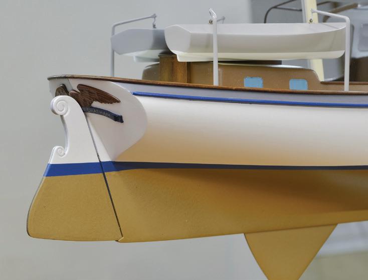
158
Shaving desiccated glue from the miter surface of one of the backboard’s frame components.
New mahogany splines in the mortises in one corner of the backboard frame. The grain of the splines is perpendicular to the miter so the splines won’t split if the frame twists.
After gluing, the splines are dressed to the surface of the frame with a chisel.
A A B C C
Right. Brass hanger straps (A) on the back of the backboard transfer the weight of the glass from the bottom rail (B) to the wall. The two mounting holes for the model are just visible (C). Far right. Ocean Pearl mounted on her new mirror. Notice the reflection is dimmer than the actual model.
Leather washers protected the edges of the holes in the glass from the steel. The leather was dried and hard, so the old washers were replaced with new leather. Roundhead Phillips screws were used in place of the originals because I felt they would be less likely to stress the edges of the glass.
Observations
A few qualities of the display are worth mentioning. Notice that the camber of the middle section of the trunk cabin, the portion over the first two large ports, flows naturally through the centerline and the taffrail does, also. This shows that they meet the mirror in curves that are tangent to a line perpendicular to the mirror’s surface. However, the top of the pilothouse appears to have a ridgepole along the centerline. I am sure this is not how Dunbar designed the boat. If the model had been mounted on a non-reflective surface, this would not have been as noticeable.
Comparison of before (page 154) and after images of the stern illustrate just how deteriorated the model had become. Bare spots along the top of the transom show that the original paint had fallen away from the end grain
of the hull block as it dehydrated. Two dark spots in the bare area show where ferrous pins fastening the taffrail to the stern had rusted and bled into the wood. The distinct yellowish cast on the white paint indicates the degree to which tobacco smoke had affected the finish.
The before image was not taken with the model on the mirror, but the after image was. In it, notice how the reflected area of the transom to port is quite a bit darker than the starboard side. The same is true of the ship’s boat. This dramatically indicates how much light the mirror absorbs. And this, in turn, indicates why, even with the reflective surface of the mirror on the front face, this sort of display cannot make a half-hull model look entirely like a full-hull model.
I pondered how to photograph the model on the mirror and not capture me and what was behind me. Usually, objects are shot with a plain backdrop directly and squarely behind them. But, in this case, the white backdrop was erected behind me. The model was canted so the plane of the mirror was not parallel to the backdrop. Then the tripod was set slightly to one side of the center of the model. Thus, from the camera’s vantage, the mirror reflected only the backdrop, and the model appeared to be floating on air. ¯


The arrangement for the back drop (A), the model (B), and the camera (C) for shooting the mirrored model so the camera is not in the image.
The finished model on the new mirror backboard.
159
A B C
Addendum
Various topics and examples that warranted inclusion just couldn’t, for a few reasons, find comfortable homes in Part Three, Practices and Applications, or in Part Four, Case Studies. So, I present several of them here as an Addendum of annotated phtographs. Some offer closure or addtional in-
formation on models mentioned earlier; some follow processes on models for which I didn’t have enough material for Case Studies; and some offer thoughts on ship modeling. Several of the models and conditions have already been mentioned, and some appear in this section for the first time. ¯
If you were troubled by the wreckage of the prisoner-of-war model on page 26, this image may ease your mind. It was taken after the work was complete on the model and the baseboard.


The two images below illustrate the progressive ravages of dehydration. The first image (A) was taken in March 1983; the second (B) was taken fourteen years later, in April 1997. This is an athwartship deck edge, curtain plate, and railing on the 1:48-scale model of Orontes. The ruled deck panel was firmly attached to the model’s sides. As the panel dried out and shrank, it was torn down the middle. Meanwhile, the hull, which was also shrinking, pushed the two parts of the deck panel together, closing the deck split somewhat. The thin white wooden curtain plate had its grain going athwartship. Being compressed, it had nowhere to go, so it buckled, pulled out nails, and fractured glue lines. Notice how much greater the buckle is in the later image. Also notice that the brown, ruled grating on the hatch at the bottom has faded in direct sunlight.

161
A B


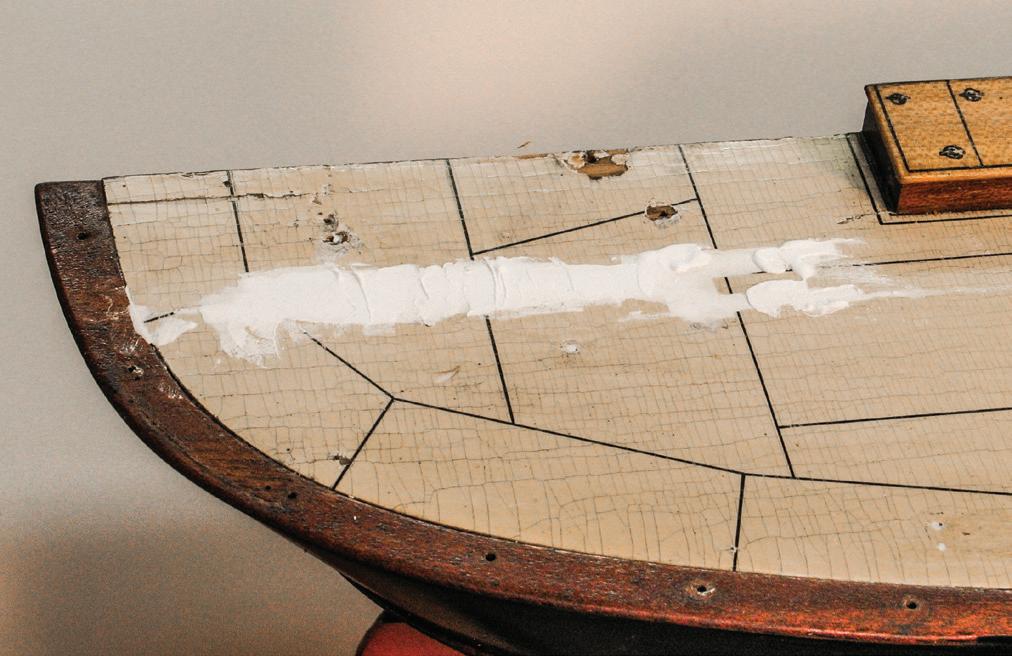
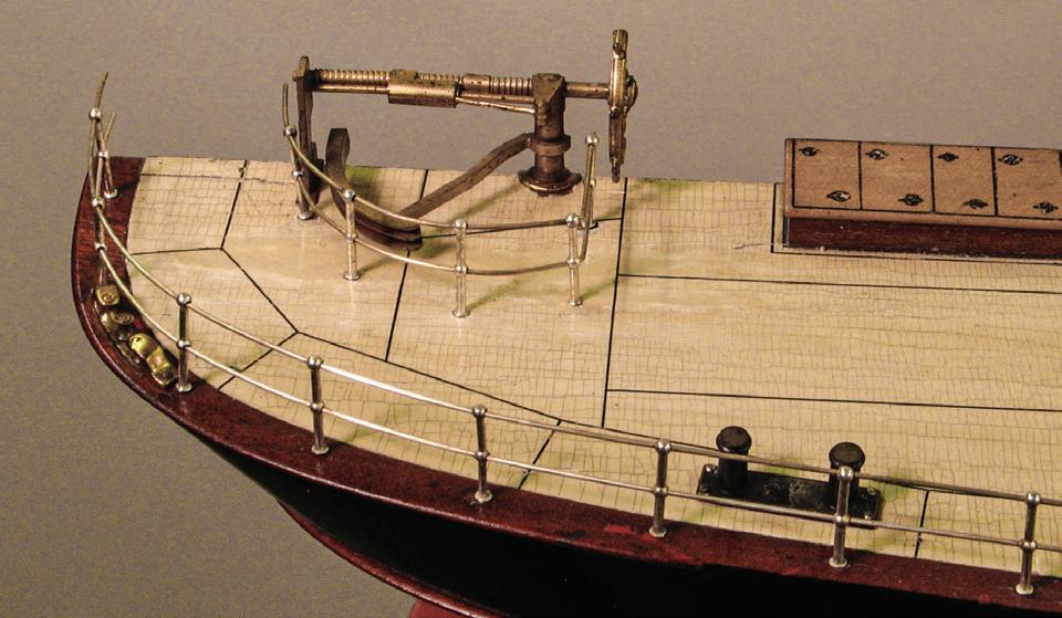
The after deck on this model was painted and ruled to represent metal plating. The paint developed severe and losses and craquelure (A). I removed all adjacent fittings and structures, then filled areas of loss with Lepage Polyfix (B) and smoothed it to the original paint surface by scraping with a razor blade (C). After in-painting and reinking the rules, the fittings were reinstalled (D). This is a partially rigged, 1:64-scale, 67-inch builder’s half-hull model of the 1912 turbine ship Gresham. The great surprise was discovering that the back of the model exhibited the vessel’s interior (E) with both two- and three-dimensional work. While those crates and boxes are drawn on a flat surface, each of those gray sacks is an indiviudal piece. Unfortunately, the turbine is not in this image, but it is distinctly different from the triple-expansion steam engines of this period.
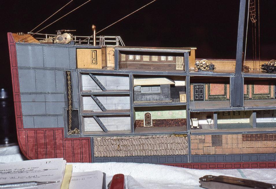

162
A
C
E
These lines of the 1843 packet ship Yorkshire (Case Study 10) were drawn by Charles Philip Kunhardt from shipyard offsets. They are typical of the lines published in William H. Webb’s magnificent Plans of Wooden Vessels of 1895.
B
D
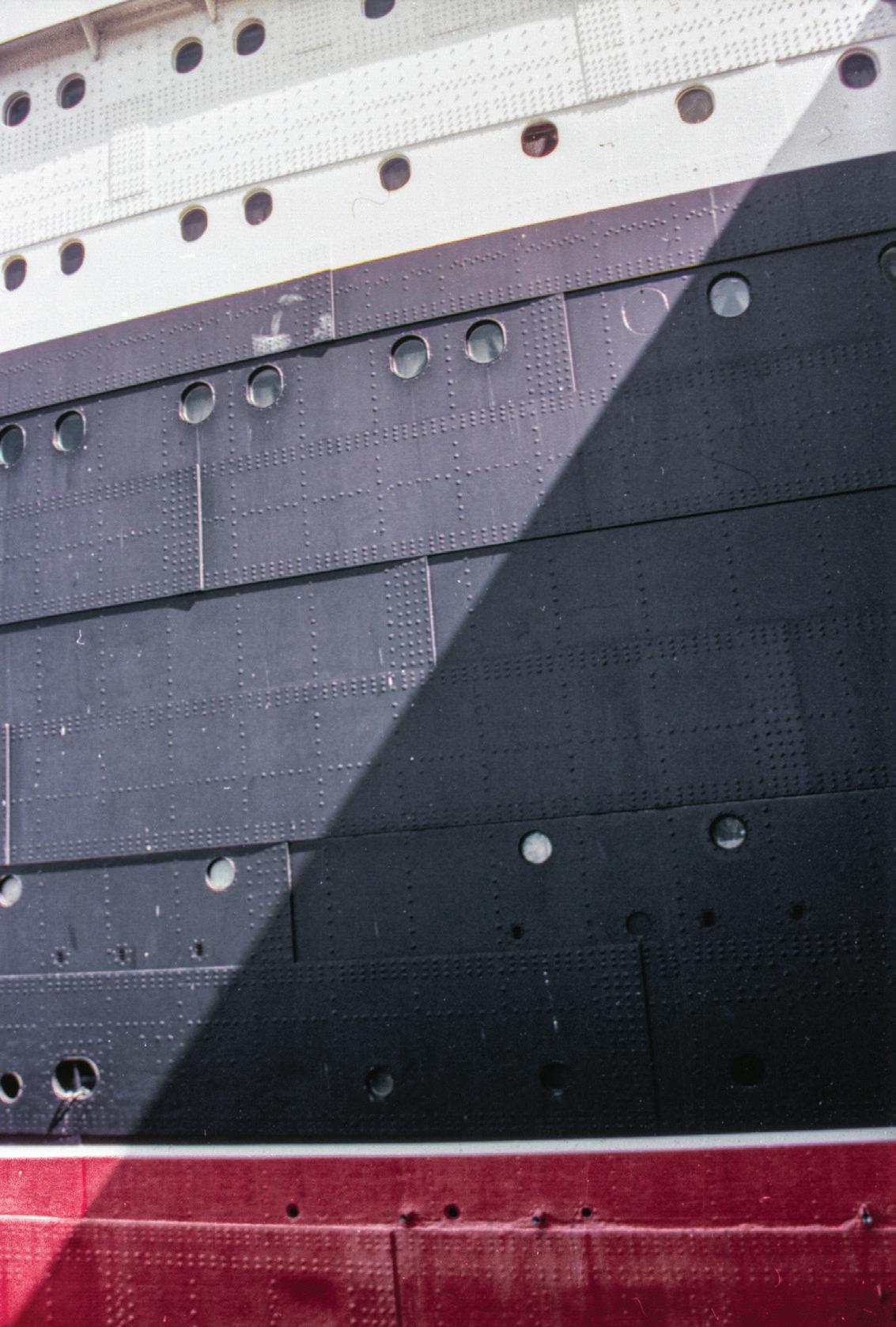

Above. For some models, simple sketches aren’t enough for recording information. I rendered Elena (Case Study 22) in Adobe Illustrator at the same size as the model (about 34 inches on deck) to document rigging leads, block usages, sail sizes and construction, and much more. I made a similar rendering of the deck and its structures.
Mulbera
4½
pump
After five
the
Study 20).
Here, forward is to the left. The shadows along the bottom edges of the black plates reveal how the aft each plate bends outward to overlap the forward end of the next plate aft. The dense pattern of rivets everywhere traces the internal arrangement of frames and other structural components. Notice how subtle the porthole fittings are compared to those on the 1:48-scale model of Orontes on page 34. Also notice how details are much less evident in the shadow.
a
in its own right
on a cherry base. The combination of black and silvered parts provides depth and texture, even though the silvered parts are probably not realistic. Ships’ boats cannibalized from a model that will be discarded, as this windlass was, at 1:48-scale or larger, also make interesting stand-alone models.

163
Above. This is the port side of the magnificent Cunard liner Queen Mary. Raking sunlight casts shadows that accentuate the visual texture on the sides of this ship that was constructed with strakes of riveted steel plates. On formal builders’ models, vessel sides are rendered completely smooth and free of texture. Compare the texture in this image with the lack of texture on the builder’s model of Doctor Saboia (Case
Right. The steam-powered anchor windlass from the 1:48-scale model of
is
inches wide across the
brakes.
minutes in
ultrasonic cleaner, it looks fine as
model
mounted
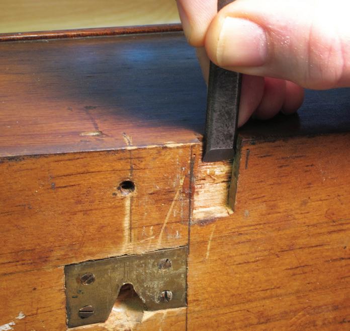

Above. Stub masts and bowsprits were common details found on half-models. Generally fitted into mortises in the backs of the hulls, they had good support when the model was on a backboard. But stub spars on models without backboards were subject to fracture and loss.
As a motif, the visible ends of stubs were usually sculpted with a false “break.” Interestingly, some modelers had what might be called signature patterns for these breaks ranging from a clean bevel to rounded or spikey styles.
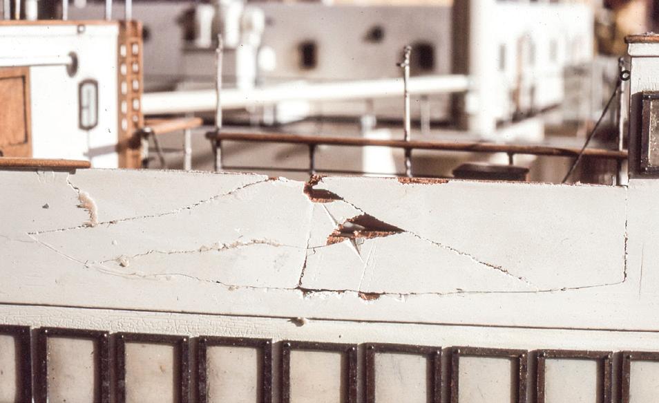

A B C D
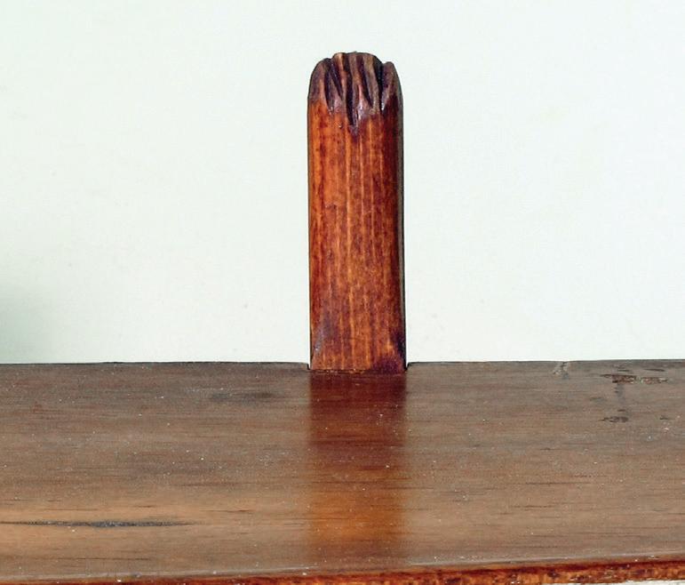
Stubs are easy to make or replace. In this series, a stub mast was being replaced on a contemporary 1:32-scale model of the 1893 America’s Cup defender Vigilant. At A, a chisel is being used to clean old glue out of the missing stub mast’s mortise. At B, a piece of new pine has the same grain pattern as the original stub bowsprit nailed into its mortise. At C, the new stub mast has been fitted to its mortise and has been rendered 8-square above deck level. At D, the stub has been cut to length, the “break“ has been sculpted to match the bowsprit’s; and finishing and installation are complete.

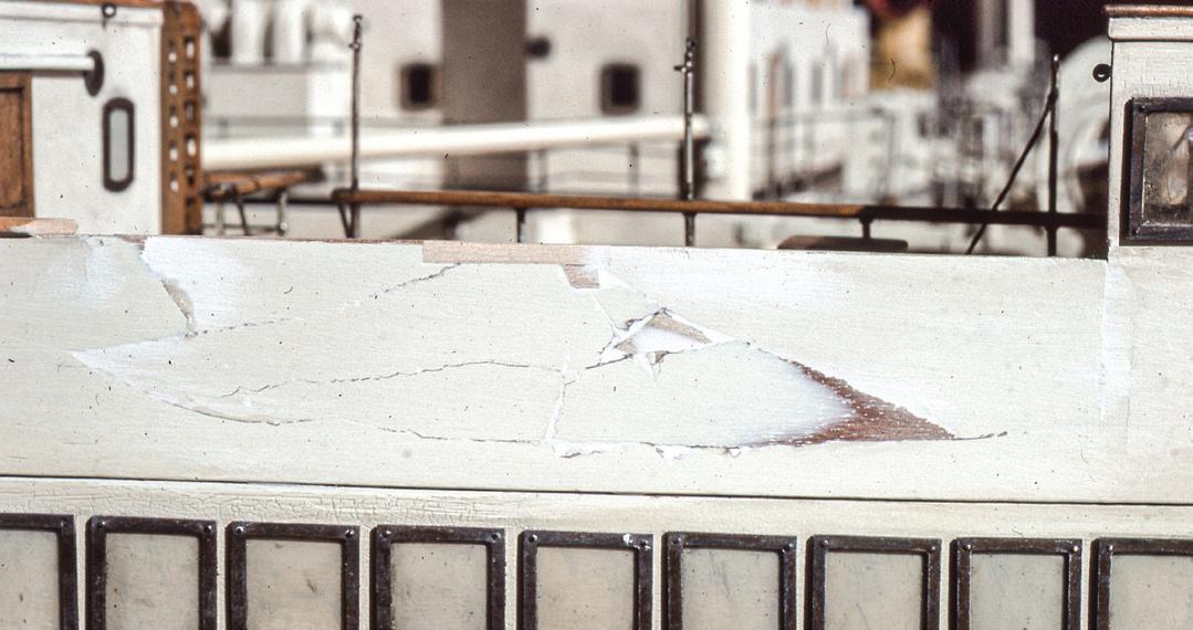
Repairing the shattered bridge bulwark on the 1:48-scale model of Rangitiki (page 21) was an interesting job. I recovered original bits of the bulwark from around the model and worked them together (A). After test fitting, they were glued in place using squeeze clamps and thin basswood cauls on the bulwark’s fore and after faces to enforce its curvature (B). Next, I worked basswood graving pieces into the larger gaps (C). After they were faired to the surface, interstices were filled with compound and sanded (D). Finally, the repair was in-painted (E).
Notice that each window on the deck below the bridge is an individual brass frame pinned to the bulkhead. The windows’ plastic glazings have faded and lost all their color.


164
A
D
B
C E


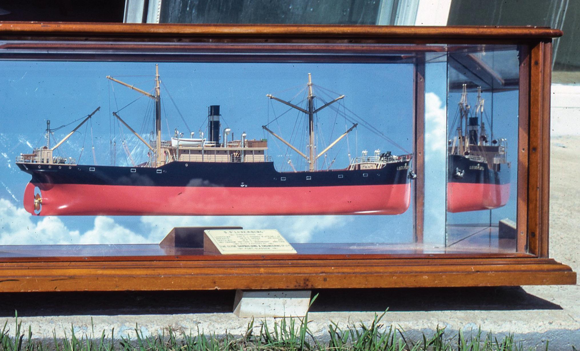
Half-models were sometimes built complete with superstructure, masting, and rigging. They were truly half of a model. They required the same protection as full-hull models and were occasionally mounted on mirrors like Ocean Pearl (Case Study 29). This example is a 1:96-scale, 29-inch-long, rigged half-hull builder’s model of the 1910 Scottish steamer Luxemburg. The reflection in the mirror is the actual blue sky with clouds. The ends of the case were fitted with vertical mirrors angled 45-degrees to the backboard, so the model’s ends could be seen when looking straight into the case (left). In the image of the bow (right), notice that there is no visible seam between the model and its reflection; the only aberration is that the rigging lines on the centerline are doubled. Also notice the silvered fittings and that there is no representation of shell plating.
The builder’s model of the 1901 steamer Sicilia (page 22) was equipped in her fore and after waists with small steam-powered deck cranes for cargo handling (far left). One was missing. For a replacement, I gave one of the survivors to the late Chris Morrison, a Boston-based ship modeler. He fabricated such a perfect copy (left and below) that I can’t tell, now, which one is the original.
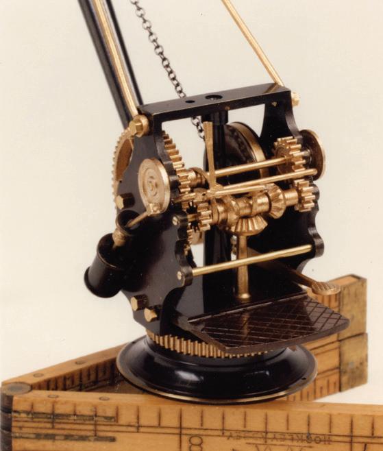

165
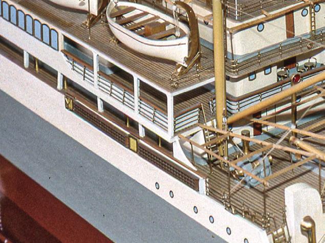


Accommodation ladders are designed to lie flat for storage along a ship’s railing or bulwark (A) and to be rigged down a vessel’s side to the water to facilitate boarding from boats alongside. At a ladder’s top, an upper platform articulates to the ship’s deck edge (B) or to the ship’s side at a doorway (C). A ladder articulates to the upper platform (D) and a lower platform articulates on the ladder near the water (E). Some longer rigs have two ladders and and an intermediate platform. The entire rig is suspended by tackles (F) that hang from small davits (G) at deck level and that attach to spans (H) just above the ladders. A spar or fender (I) is sometimes seen protruding below the lower platform and the waterline. This is to prevent boats from coming up under the platform when it’s rough.
Beyond being interesting features, accommodation ladders serve a real function on builders’ models: They provide a necessary sense of human scale to the otherwise unscalable topsides, especially of larger ships.
These fragile, complex structures take beatings on uncased models. They can be destroyed easily. Most of the parts (J) of this two-ladder, three-platform system are present and in good shape and only require reassembly. At K, there are only remains, including slats, steps, rails, gratings, pins stanchions, and blocks; to the left are pearwood strips that have been milled to replace broken and missing components.
Clockwise from the upper left, the details shown are from the 1:64-scale, builder’s full-hull model of the 1949 British steamer Armanistan; Orontes; Mulbera; Lanfranc; and the 1:48-scale, builder’s half-hull model of the Norwegian steamer Normand. See also the models of USS Juneau (page 11) and Magdalena (page 54).

Left. Here’s what can happen when you don’t inspect a model thoroughly before picking it up. Don’t let this happen to you. (Photograph by Racket Shreve)

Below. The heat-scorched 41-inch model of Admiral Fraser from which the pile of parts shown on page 49 was stripped before the model was regretfully discarded.

166
J K A F H B E F G D D C I E
Epilogue
Arecurring drawback to ship modeling is that it takes so bloody long. Months, if not years, may elapse between moments when a modeler is able to sit back and experience the satisfaction of having completed a project. The solution is to divide lengthy projects into subsets and to be pleased with them. Instead of waiting to breathe a sigh of relief when an entire model is finished, relax when the steering wheel is done. With this book, it was one Case Study at a time. I have always understood this as paying attention to the trees rather than the forest. Maybe this contributes to how I feel when a major modeling job is complete. I have walked the paths among the trees, they have led me into a forest, which I now understand, and I am ready for new paths. This is to say that when work on a model (or book) is finished, I harbor no sadness for its departure.
The making of this volume has brought into view only some of the many forks I’ve encountered along the paths of my ship-modeling journey. I hope I’ve avoided treading too heavily where my route intersects those of other professionals. I’d like to have shared more lessons, delights, and oddities, but everyone must draw the line somewhere.
When people who don’t know me learn my profession, they frequently hasten to inform me that I have “lots of patience” and “steady hands.” Little do they know that my hands have quivered my entire life, and they do so more now, with age. And those who do know me are quick to point out that patience is not something I exhibit abundantly in day-to-day living. The late George Kaiser, a colleague in Boston’s USS
Constitution Model Shipwright Guild, once said to me the words that are this work’s epigraph. I endeavor to keep them in mind. Just to set matters straight, I considered calling this book “Neither Patience nor Steady Hands,” but who would have opened it? Acquaintances, friends, and colleagues frequently express concern about the future of ship modeling. They see ship modelers as a group of silvering individuals with few up and coming young people in the ranks. “Who,” they ask, “will carry on the traditions of artistry and craftsmanship that seem to be fading with the advent of the cyber age?” “What will you do,” they fret, “to attract younger people to your world?” I have been cornered at cocktail parties by zealous individuals who demanded to know, knuckle-thumping my chest, what I am doing about this, that it is my responsibility. But I see that my responsibility is to care for ship models and to share my experience through writing and lecturing. This is what I am doing for the future.
Acknowledgments
Unlike books that follow the step-by-step growth of new model construction, the path this one follows depends not as much on its author as on the original modelwrights. They, by their efforts, created opportunities for me to learn. Without their models for me to care for, I would have nothing to report.
Model building and writing are generally solitary occupations. But I have been fortunate that many individuals have taken time to help me find my way, and I
want to recognize them. I have kept this list for many years, yet know it must have omissions. I apologize to those I have overlooked.
The list that goes back the farthest includes folks who have worked with me in the trenches of ship model repair, either in my home shop or on the road. Each lightened my load, dispelled tedium, and added perspective: Alex Bellinger, Dan Benfield, Alice Dickinson, Carol Gates, John May, Bill “Banjo” Montague, Harry Morgan, Chris Morrison, Tom Odell, Chip Raymond, Racket Shreve, Peter Sweetser, J essica van Dam, and Cathy Walsh.
I owe so much to the professional conservators who have shared insight from their esoteric world. Thank you Mimi Leveque and Jessica van Dam of the Peabody Essex Museum; Sherry Phillips, of the Art Gallery of Ontario, Toronto; Deborah Bede, Meredith Montague, Gerri Strickler, and Mei-An Tsu of the Museum of Fine Arts; and Melissa Carr, Masterwork Conservation, Arlington, Massachusetts.
Institutions that supplied images are acknowledged in captions. But I happily thank Melissa Carr, Peter Hickey, Dawn Rabinowitz, Racket Shreve, and Bob Steinbrunn for their individual contributions. Images from my youth were captured by my long-departed aunts Alice Beal Baker Hyde and Elisabeth Napier Ovans.
There wouldn’t have been a book without the models. Permissions to include many of them were granted by Dan Benfield of the New York Yacht Club; Ned Bullis and Ron Woodward of the Eastern Yacht Club; Gregg Dietrich of the North Star Gallery; Bartlett Dunbar; Andrew W. Edmonds; Erin Harkness McKinnon; Arnold and Henry Kriegstein; Orson D. Munn; Harrie Slootbeek of the USS Con-
stitution Museum; Rob Snedeker of the Larchmont Yacht Club; and Joan Whitlow of the Custom House Maritime Museum.
Then there are those people who may not realize they had done anything to help, yet had, even if only in a small way. Thanks to Matt Brenckle of the USS Constitution Museum; John Cheevers; Roger Cole; Ryland Craze; John Fisher; Kirby Francis; David Hill; Llewellyn Howland III; Harold Lincoln; Dan Martin of Collector’s Showcase, Granby, Massachusetts; Heather Moran of the Camden (Maine) Public Library; Carole Mowrey and Paul O’Pecko of Mystic Seaport Museum; W. Michael Mroz of the Custom House Maritime Museum; Neal E. Parker; Bill Partridge; Mike Prendergast; Grant Walker; Christopher and Sarah Watts; Dana Wegner; and John Wyld.
By reading all or parts of the manuscript, Howard Chatterton, Ray Crean, Mike Ellison, Adrian Humphreys, and Sherry Moore each provided insight that shaped the narrative. To Patricia Egan I offer special thanks for her eagle eye in proofing.
¯
This book has been as demanding as any ship-model project could possibly be. It would not have come to fruiton without the youthful input of Mike Ellison, who assumed the leadership of SeaWatch Books after Bob Friedman retired. Mike has been open and helpful in every way. He has graciously allowed me broad latitude and provided great support in managing the conception, writing, and design of Caring for Ship Models. Finally, I thank my wife, Sherry Moore, who has been ready whenever I have needed feedback, perspective, and that most-imortant element, time. ¯

168
Notes
Abbreviations
AGO Art Gallery of Ontario, Toronto
CHMM Custom House Maritime Museum
HHC Haffenreffer-Herreshoff Collection
HNC Francis Russell Hart Nautical Collections
MFA Museum of Fine Arts, Boston
MIT MIT Museum
MMM Maine Maritime Museum
MSM Mystic Seaport Museum
NYYC New York Yacht Club
PEM Peabody Essex Museum
USNA United States Naval Academy
Notes for Part One: Prologue
Pages 3 through 6
1 Remington, p. 79.
2 Grahame, p. 35.
3 Friedman, conversations, 2014–15.
4 MacAdam, conversation, 1967.
5 Wouk, p. 131.
6 Napier, AGO, Transfer.
Notes for Part Two: Perspectives on Ship Modeling
Pages 7 through 20
1 Napier, “Looking at Ship Models,” 2000.
2 Lane, p. 81.
3 Napier, “Historical Accuracy,” pp. 255–256. For discussion of what is important to museums, see Von der Porten, pp. 253–254.
4 Napier, “Historical Accuracy,” pp. 255–256.
5 Wegner, “Museum Standards,” p. 47.
6 Napier, “Historical Accuracy,” pp. 255–256.
7 Tomkins, pp. 48-49.
8 Respect for original modelers idea developed with Joan Parks Whitlow, 2017.
9 culturalheritage.org; and Phillips, conversations, 2008.
10 culturalheritage.org.
11 Phillips, conversations, 2008.
12 For expansion on this theme, see Napier, “Perspective.”
13 Gunesch, p. 152.
14 Steinbrunn, Sanborn, Antscherl, Feldman, and Filipowski, e-mails, 1–9 June 2011.
15 Herbert, p. 8.
16 Poole, conversation, 1967.
Notes for Part Three: Practices and Applications
Pages 21 through 56
1 Francis, conversation, 2021.
2 Napier, “Notes on the Ship Models.”
3 lannangallery.com.
4 Katherine Twomey, conversation, 2006.
5 Tom Ruggiero, conversation, undated.
6 Allen L. Baker, conversation, 1975.
7 Dana Wegner, conversation, 1995.
8 Wegner, “Lead Corrosion.” Wegner was able to take advantage of Navy resources to research this issue.
9 Murdock, p. N:3-4.
10 Murdock, p. N:16.
11 Murdock, p. N:15-16.
12 Underhill, Plank-on-Frame Models. Vol. 1, p. 97. Thanks to Mark Sceery.
13 Leveque, conversation, 2021.
14 wikipedia.org/wiki/Cotton_swab; and Schueller, “Cotton Swab,” 2012.
15 Sumrall, conversation, 2006.
16 Napier, AGO, G-132
17 Van Dam, conversation, 2021.
18 Napier, AGO, Unidentified Frigate.
19 Hume, pp. 80, 92–93.
20 cameo.mfa.org.
21 Leveque, conversation, July 2021.
22 Traditionally called a “Dutchman,” I prefer politically neutral “graving piece.”
23 Napier, AGO, T.C.C. Hopper No 1
24 Francis, conversation, 2021.
25 Napier, AGO, Unidentified Sternwheel Steamer.
26 Napier, AGO, Breda
27 Napier, AGO, Bristol
28 Napier, AGO, Golconda
29 Napier, AGO, T.C.C. Hopper No 1
30 Dyson, conversation, 2012.
31 Wegner, conversation, June 1991.
32 Shreve, conversation, 1991.
33 Napier, letter to Larson, 1999.
34 Hoving, conversation 1996; and Leveque, conversation, n.d.
35 For more on making line, see: Napier, ValkeniSSe, pp. 154–156.
36 For more on fiber reactive dying, see: Napier, ValkeniSSe, pp. 156–158.
37 Stephens, conversation, 2012; Napier, AGO, Breda; and Napier, MFA, Brig-Rigged Corvette.
38 MFA, Flying Cloud, 35.42; McLanathan, images 40–41; and Woods and Napier, “A Fresh Look.”
39 Napier, AGO, Melpomene.
40 (Boucher Ship Models), Scale Models of Famous Ships, p. 92.
41 Ronnberg, Fishing Schooners, p. 85.
42 cameo.mfa.org/wiki/Crepeline.
43 Napier, “Taking the Act on the Road,” pp. 88-95.
Notes for Part Four: Case Studies
Pages 57 through 159
1 Kriegstein, p. 67.
2 Kriegstein, pp. 65–67; and Culver, pl. 36.
3 Anderson, p. 61.
4 Lees, p. 44; and Anderson, p. 61.
5 Lyon, pp. 71-72.
6 Anon., “Donald McNarry,” obituary; and Fisher, e-mail, 30 April 2000.
7 McNarry, Ship Models in Miniature, p. 10; and Anon., “Donald McNarry,” obituary.
8 Anon., “Donald McNarry,” obituary; and Friedman, conversations, 2014-15.
9 Feldman, conversations, 1990s.
10 McNarry, Ship Models in Miniature, p. 9.
11 McNarry, letter, 1977.
12 McNarry, letter, 1977.
13 McNarry, letter, 1996.
14 Martin, p. v.
15 McNarry, Ship Models in Miniature, pp. 84, 87.
16 McNarry, Ship Models in Miniature, pp. 14, 84, 87.
17 Preul, conversation, 2015; and McNarry, Ship Models in Miniature, p. 87.
18 McNarry, Shipbuilding in Miniature, pp. 33, 75–76.
19 Regretfully, I have no citation for this.
20 McNarry, Shipbuilding in Miniature, pp. 106, 107.
21 McNarry, Shipbuilding in Miniature, p. 107.
22 McNarry, Shipbuilding in Miniature, pp. 126, 128.
23 Carr, report, 28 May 2015.
24 McNarry, Shipbuilding in Miniature, p. 128.
25 Carr, e-mail, 8 May 2015.
26 Walker, e-mails, 22–24 March 2022.
27 wikipedia.org/wiki/Bombyx_mori.
28 Horie, The Conservation of Decorative Arts.
29 Anon., “Ship News, Port of Philadelphia; Lyon, pp. 84, 86, 123, 275; and prints.rmg.co.uk/category/Ship-plans.
30 Lyon, p. 276.
31 Lyon, p. 2.
32 Phillips, Ship Registers, pp. 111–12; and Cheney, p. 50.
33 Inez, half-model, CHMM.
34 Brewington, Paintings and Drawings, p. 370; and PEM, object M3762.
35 Phillips, Ship Registers, pp. 111–12.
36 Baker, p. 497; and Chapelle, Watercraft, p. 7.
37 Howland, “William H. Webb,” pp. 119–121; shipbuildinghistory.com; and sname.org.
38 Dunbaugh and Thomas, pp. 151, 153, 162; Chapelle, Search for Speed, p. 276; Cutler, Queens, pp. 377, 564, 565; Webb, p. 86; and Albion, Square-Riggers, pp. 193, 226.
39 Ronnberg, “Plans of Wooden Vessels,” p. 62; and Stephens, Traditions and Memories, p. 36.
40 Carberg, pp. 62, 63, 165; fold3.com/document/14744790; and Bohlin, The Boston Globe. Mystic holds Ness’s models of Charles W. Morgan (as a ship) and Lagoda; the Science Museum holds 1:48 models of Charles W. Morgan (as a ship) and Flying Cloud.
41 Cheevers, e-mail, 2015; and Lincoln, e-mail, 2016.
42 Greenhill and Giffard, pl. 26.
43 Frizot, pp. 233–34.
44 Odell, interview, 2015.
45 Canney, p. 126.
46 Dunbaugh and Thomas, p. 222.
47 Roberts, “Dunderberg,” pp. 363–400; Anon., “Dunderberg Afloat,” 1865; and Navy Department, American Naval Fight-
170
ing Ships, Vol. III, p. 609.
48 Anon., “Dunderberg Afloat,” 1865; Hall, p. 116; Canney, p. 127; and Howland, conversation, 2016.
49 Canney, pp. 128–129; William H. Roberts, “Dunderberg,” pp. 363–400; and Stephen S. Roberts, “Rochambeau,” pp. 333–345. There is no mistake: Dunderberg articles by two authors named Roberts appeared in one issue of Warship International. W. Roberts reported the interminable struggle between Webb and the Navy over the ship’s design, production, and cost; the article includes the ship’s contract and modern interpretations of her plans. S. Roberts discussed the vessel’s life in France.
50 William H. Roberts, “Dunderberg,” p. 364; Wegner, e-mail, 2015; and Golden, e-mail, 2015.
51 wikipedia.org/wiki/Musée_national_de_la_Marine.
52 Canney, p. 126.
53 William H. Roberts, “Dunderberg,” pp. 368, 383, 385, note 33.
54 Nevr-Dull Magic Wadding Polish, Material Safety Data Sheet; and Carr, e-mail, 31 July 2015.
55 Riff, Landlocked Sea Captain; and Partridge, interviews, 23 October and 3 December 2015. LaBaron-Bonney (the name combined one Atherton brother’s first name and the other’s middle name) survived until 2020 in Amesbury, Massachusetts, as custom upholsterers for antique and classic cars.
56 Partridge, interviews, 23 October 2015 and 7 January 2016.
57 Lubbock, Down Easters, p. 2.
58 Fairburn, Vol. III, p. 948.
59 Bunting, A Day’s Work, p. 310; and Lubbock, Round the Horn, pp. 3, 34.
60 Hall, p. 64; and Butts, pp. 16–17.
61 American Lloyd’s Registry (1865), pp. xv, xvii.
62 Palmer Rigging Records, MMM; and Anon., “Vessels Built by John and Justin L. Taylor,” PEM.
63 Howard Chatterton, e-mail, 2015.
64 Chapelle, Boatbuilding, p. 209.
65 Davis, Ship Model Builder’s Assistant, p. 30.
66 Davis, Built-Up Ship Model; Parker, interview 2015; Brig Lexington, model, MSM Object 2010.4; and Hahn, pp. 4-11.
67 Parker, interview, 2015.
68 Davis, Built-Up Ship Model, pp. 13, 23, 28.
69 Davis, Built-Up Ship Model, pp. 33, 53.
70 Guérin, p. 77.
71 Fox’s Yachting Annual, pp. 6–7, 42–43; and Stephens, Traditions and Memories, p. 163.
72 Putnam, pp. 54–55; and phillipslibrarycollections.pem.org.
73 Putnam, p. 62, 69; and Lubbock, Down Easters, p. 110, 111. The other ships were Sooloo (II) (1861), Mindoro (1864), and Formosa (1868). For additional material regarding the building, outfitting, and career of Sooloo (II), see the Napier, “Sooloo (II) of Salem History and Research for Building a Model.”
74 Panay, plan, PEM.
75 Freeston, p. 156.
76 (Richard A. Bourne Co. Inc.), lot 120.
77 American Yacht List (1881–1897).
78 Candage, “Boston Ship Builders”; Chapelle, American Sailing Ships, p. 334; Chapelle, Watercraft, p. 5; Chapelle, American Sailing Craft, p. 222; Bunting, Steamers, Schooners, Cutters, and Sloops, p. 52; and Robinson and Dow, p. 10.
79 American Yacht List (1881–1897).
80 Stephens, American Yachting, p. 162; Stephens, Traditions and Memories, p. 173; Chapelle, Yacht Designing, p. 75.
81 Stephens, Traditions and Memories, p. 168.
82 The American Yacht List, 1881–1897; Anon., Blue Book of American Shipping, p. 74; Foster, p. 235.
83 constantines.com. The company was founded in 1812, survived in New York until 2001, and at this writing continues, family-owned and more than two centuries old, in Fort Lauderdale, Florida, as Constantine’s Wood Center. They still sell boxes of fifty veneer samples.
84 Herreshoff, Wizard of Bristol, p. 170; and Chevalier and Taglang, pp. 189–190.
85 Stephens, Traditions & Memories, pp. 200–201; and Herreshoff, Wizard of Bristol, p. 169.
86 Anon., “Colonia as a Schooner,”; Corona, plan, MIT; Stephens, Traditions & Memories, p. 339; Garland, p. 78; Herreshoff, Wizard of Bristol, p. 178.
87 Herreshoff, Wizard of Bristol, p. 324.
88 NYYC, Model Committee Report, p. 5.
89 forums.wcha.org; and wikipedia.org/wiki/John_Warne_ Gates.
90 Anon., “Personal,” p. 54; Anon., “Gates’ Yacht Missing,” 1903; and Anon., “Gates’s Yacht Here,” 1904.
91 Lloyd’s Register of American Yachts (1905/06), p. 154.
92 Anon., “Quarter-Deck Talk,” p. 18; Anon., “Yachts Change Hands,” p. 183; and Anon., “Sales and Charters,” p. 118.
93 Anderson, “Voyage of the Roxana,” 1917.
94 Lloyd’s Register of American Yachts, 1906, p. 202; 1910, p. 217; 1927, p. 246; and 1931, p. 304.
95 Kelly, “Portrait of a Great American”; Rawston, e-mail, 2017; and Conn, p. 5.
96 Kelly, “Portrait of a Great American”; and Anon., “Horace E. Boucher,” obituary.
97 Anon., “Shipyard High in a Skyscraper,” p. 268; Anon., “The New Boucher Showroom,” p. 35; Anon., “Two Yachts Sail in Bermuda Race,” 1910; Anon., “Sailing on Gravesend Bay,” 1910; Rousmaniere, p. 309; and historytoy.com.
98 Anon., “Paton Lewis,” obituary; findthecompany.com; and www.bluejacketinc.com.
99 Anon., “Horace E. Boucher,” obituary; Rousmaniere, p. 305;
171
Fletcher, letter to Hipkiss, 1935; Davis, “Diary,” 21, 23–27 October 1922; Anon., “New Boucher Showroom,” p. 35; Napier, Legacy, pp. 22–23; and Ratliff, p. 16.
100 Lloyd’s Register of Shipping, 1915.
101 lr.org/en/research-and-innovation.
102 plimsollshipdata.org
103 Rousmaniere, p. 137; Bray and Pinheiro, p. 88; Lloyd’s Register of American Yachts, 1912–1942; and Elena, #679, Catalogue of Models, NYYC.
104 Elena, #679, Catalogue of Models, NYYC; Elena, model, MSM; and Davis, “Diary,” 26 October 1922.
105 Napier, elena Sails Again; and Dickinson, e-mail, 2021.
106 Napier, “Notes on the Ship Models,” MFA, 7 May 1991–26 June 1992; and Keble Chatterton, pp. 46–47.
107 Elena, #679, Catalogue of Models, NYYC.
108 Fletcher, undated note, MFA.
109 Fletcher, undated note, MFA.
110 Falino, “Conservation Record,” MFA, 1988; and Derrick, “Analysis Summary for 35.42,” MFA, 2009.
111 Derrick, “Analysis Summary for 35.42,” MFA, 2009; and e-mail, 2009.
112 Elena, plans, MIT.
113 Boucher, Blue Ribbon Working Models, p. 92.
114 Barnard, telephone conversation, 2017.
115 Elena, plans, MIT; Herreshoff, Wizard of Bristol, p. 178.
116 Elena, plans, MIT.
117 Leveque, “Treatment Report for 35.42,” MFA, 1988.
118 Boucher, Models of American Ships, p. 61.
119 Preston, p. 249; Navy Department, American Naval Fighting Ships, Vol. I, p. 61; and Silverstone, p. 20.
120 fineartmodels.com.
121 Preul, “Research Compiled for the Painting of the USS Arizona Model,” 2011.
122 Lloyd’s Register of Shipping, 1919; wrecksite.eu/ownerBuilderView; and archiver.rootsweb.ancestry.com.
123 Wyld, e-mail, 2015.
124 Curacoa, plans, Profile, No. 377033, Forecastle & Bridges, No. 377033a; and Whitley, p. 68.
125 Whitley, p. 70; Anon., “Hit by Queen Mary,” 1945; and Scheetz, p. 19.
126 Fisher (who knew Ough personally), interview, 1997, and letter, 2000; Arthur-Brand, p. 376; Ough, “Modelling a Whole Fleet,” pp. 174–175; and Altham, p. 241.
127 Curzon, letters to Ough, 17, 26 July, 6 May 1928, now Lord Howe, 3 May 1930; Colquhoun, letters to Ough, 27 November 1930, 6 May 1931; Vercoe, p. 270; and Ough, “How I Modelled the ‘Queen Elizabeth’,” p. 207.
128 Mountbatten, letters to Ough, 21 March 1934, 14 August
1935; and Lees, letter to Ough, 1 August 1939.
129 Arthur-Brand, p. 378; Roach, p. 17; Anon., “Norman Ough,” obituary, p. 393; and Fisher, letter, 2000.
130 Fisher, e-mail, 2000.
131 Lincoln, interview, 2015; and Fisher, e-mail, 2000.
132 Fisher, e-mail, 2000; and ssgreatbritain.org.
133 Cole, letter, 11 September 2000; Ough, “All Steel Ship Model Construction,” p. 17; Curzon, letter to Ough, 8 May 1931; and Lees, letter to Ough, 21 August 1939.
134 Fisher, e-mail, 2000.
135 Roach, p. 98; Arthur-Brand, p. 375; and Fisher, e-mail, 2000.
136 Ough, “The ‘Cardiff’ Class,” p. 28.
137 Arthur-Brand, pp. 375, 376.
138 Ough, “The ‘Cardiff’ Class,” pp. 29, 33.
139 britishpathe.com/video/model-ship-curacoa.
140 Ough, “The ‘Cardiff’ Class,” pp. 28–29.
141 Powell, p. 27.
142 Ough, plans, “H.M.S. Curaçoa Light Cruiser.” Note Ough’s affected use of the cedilla; this form was not used anywhere else for this ship.
143 A gift from John Fisher. He also sent other early images of the model; some included Ough and some did not, but each helped me understand the model more fully.
144 Curacoa, plan, Profile, No. 377033; and Ough, plan, “H.M.S. Curaçoa Light Cruiser.”
145 Reed, p. 51.
146 Ough, “The ‘Cardiff’ Class,” p. 28.
147 britishpathe.com/video/model-ship-curacoa; and Ough, “AllSteel Construction,” pp. 15–16.
148 List of Merchant Vessels of the United States, 1922, p. 22; and Bowker, pp. 137, 138.
149 Anon., “Harold A. Underhill,” obituary, p. 451.
150 Underhill, Helen Barnet Gring, Plans 894, 895, 896; and Underhill, Deep Water Sail, pp. 226–227.
151 Manuscript note inside model; and Walker, e-mail, 2016.
152 wrecksite.eu; Lloyd’s Register of Shipping, 1931; and Talbot-Booth, Merchant Ships 1942.
153 Farnham, p. 286; and Fox, p. 286.
154 Smith, “F. Spaulding Dunbar,” pp. 60, 62; and Napier, “Cover Illustration.” Dunbar told me these stories, but I cite Smith for academic credibility.
155 Smith, “Ocean Pearl,” p. 24.
156 Persson, “Donald C. Rosencrantz,” obituary, p. 78; and author’s reminiscence. MSM holds Rosencrantz’s 1950’s-era full-hull 1:96 models of USS Nautilus (SSN-571) and USS Skate (SSN-578).
157 Smith, “F. Spaulding Dunbar,” p. 69.
158 Herreshoff, Common Sense, p. 6.
172
Abbreviations are listed with Notes
Unpublished Sources
Anonymous. “Vessels Built by John and Justin L. Taylor, 1838–1886,” manuscript collection. Phillips Library, PEM.
Antscherl, David. E-mail to Modelshipwrights@yahoogroups.com, 1 June 2011.
Baker, Allen L. (Ship Model Shop, Eastham, Massachusetts). Conversation with author, 1975; and letter from author, 7 June 1992.
Barnard, Mike (Gougeon Brothers, Inc., Bay City, Michigan). Telephone conversation with author, 3 January 2017.
Candage, R. B. “Compiled by R.B. Candage, Boston Ship Builders,” manuscript notebook. Phillips Library, PEM, undated, but nineteenth century.
Carr, Melissa H. (Masterwork Conservation, Arlington, Massachusetts). “Conservation Treatment Report for Ship Model Display Case by Donald McNarry.” Report to author, 28 May 2015; and e-mails to author, 8 May and 31 July 2015.
Chatterton, Howard. E-mail to author, 9 December 2015.
Cheevers, John. E-mail to author, 23 December 2015.
Cole, Roger. Letters to author, 23 August and 11 September 2000.
Colquhoun, M. (secretary to Francis Curzon). Letters to Ough, 27 November 1930 and 6 May 1931. Author’s collection.
Corona, schooner. Plan. HH.5.00428, 1-15, 29 June 1893. HHC, HNC, MIT.
Crean, Ray. E-mail to author, 15 July 2015.
Curacoa, cruiser. Plans: Forecastle & Bridges as Fitted, 24 July 1918, Reg’d. No. 377033a; of Upper Deck as Fitted, 24 July 1918, Reg’d. No. 377033b; and Profile as Fitted, 24 July 1918, Reg’d No. 377033. Admiralty, Whitehall. National Maritime Museum, London.
Curzon, Francis, fifth Earl Howe. Letters to Ough, 17 July, 26 July, 23 November 1928; 3 May 1930; and 6 May, 8 May 1931. Author’s collection.
Davis, Charles G. “Diary,” 21, 23–28, 30 October 1922. MSM. Derrick, Michele. “MFA Scientific Research Laboratory, Analy-
sis Summary for Object number 35.42, H. S. Boucher, ‘Clipper ship “Flying Cloud”’, Project number 2009-65, 6/26/2009.” MFA; and e-mail to author, 6 July 2009.
Dickinson, Alice (Curator of Collections, NYYC). E-mail to author, 23 November 2021.
Dyson, Bruce. Conversation with author, 22 June 2012.
Elena, schooner. No. 679. Catalogue of Models. NYYC.
Elena, schooner. Model. Object File 1937.91. MSM.
Elena, schooner. Plans. Rigging #692, 91-127; Rigging #692, 91128; and #706, 1911, 3/16”=1’-0, 146-23, HH.5.12136. HHC, HNC, MIT.
Falino, Jeannine. “MFA Research Laboratory Conservation Record, Examination Report and Treatment Proposal for 35.42, 16 Sept 1988.” MFA.
Feldman, Clay. Conversations with author, 1990s; and e-mail to Modelshipwrights@yahoogroups.com, 9 June 2011.
Filipowski, Bob. E-mail to Modelshipwrights@yahoogroups.com, 3 June 2011.
Fisher, John. Interview with author, October 1997; letter to author, 29 April 2000; and e-mail to author, 30 April 2000.
Fletcher, Frederick C. Letter to Edwin J. Hipkiss, 13 February 1935; and undated note, Object File 32.42, MFA.
Francis, Kirby (luthier). Conversation with author, 8 May 2021.
Friedman, Bob. Conversations with author, 2014–2015.
Golden, Kathy (National Museum of American History). E-mail to author, 10 June 2015.
Howland, Llewellyn III. Conversation with author, 12 May 2016. Hoving, Albert (ship-model curator, Rijksmuseum, Amsterdam). Conversation with author, May 1996.
Inez, ship. Half-model. Object 1975.1.687. CHMM.
Lees, H. G. (secretary to Mountbatten). Letters to Ough, 1 August and 21 August 1939. Author’s collection.
Leveque, Mimi (conservator). Conversations with author, 27 May and July 2021; and “MFA Research Laboratory Conservation Record, Treatment Report for 35.42, 29 Sept 1988.” MFA.
Lincoln, Harold. E-mail to author, 3 February 2016; and interview with author, 4 August 2015.
Sources
MacAdam, David. Conversation with author, Baja California, September 1967.
McNarry, Donald. Letters to author, 3 December 1977 and May 1996.
Mountbatten, Lord Louis. Letters to Ough, 21 March 1934 and 14 August 1935. Author’s collection.
Napier, Rob. “An Assessment of Full-Hull Ship Models at Mystic Seaport Museum,” research data. 17 August 2012.
———, “AGO, Treatment Report for Breda, SML-62.” April 2008; “——— Bristol, SML-38.” October 2008; “——— G-132, SML-056.” June 2008; “——— Golconda, SML-98.” October 2008; “——— Melpomene, SML-123.” June 2008; “——— T.C.C. Hopper No 1, SML-70.” October 2008; “——— Transfer, SML-104.” October 2008; “——— Unidentified Frigate, SML-052.” October 2008; and “——— Unidentified Sternwheel Steamer, SML-151.” October 2008.
———, Letter to Gene Larson, 30 September 1999.
———. “Looking at Ship Models.” Lowell Institute Lecture, 22 October 2000, MFA.
———, “MFA, Treatment Report for Brig-Rigged Corvette, 32.142.” September 2021.
———. “Notes on the Ship Models at the MFA, 1991 & 1992.” 7 July 1992.
———. “Notes on the Ship Models at the Museum of Fine Arts Boston, 7 May 1991–26 June 1992.
Nevr-Dull Magic Wadding Polish. Material Safety Data Sheet. George Basch Co. Inc. Freeport, New York.
Odell, Tom. Interview with author, 21 December 2015.
Palmer Rigging Records. Mark W. Hennessy Collection (MS-18, box 12). MMM.
Panay, ship. Plan. No. P-1914 F. PEM.
Parker, Neal E. Conversation with author, 10 December 2015.
Partridge, Bill. Interviews with author, 23 October, 3 December 2015, and 7 January 2016.
PEM. Object M3762.
Phillips, Sherry (conservator, AGO). Conversations with author, 2008.
Poole, Clarke. Conversation with author, 1967.
Preul, Don (ship-model curator, USNA Museum). Conversation with author, June 2015; and “Research Compiled for the Painting of the USS Arizona Model.” Paper delivered at the Western Ship Model Conference and Exhibit, Newport Harbor Nautical Museum, Newport Beach, California, 2 April 2011.
Rawston, Peter (Associate Curator of Archives and Manuscripts, Watkinson Library, Trinity College). E-mail to author, 27 November 2017.
Ruggiero, Tom. Conversation with author, n.d.
Sanborn, Joel. E-mail to Modelshipwrights@yahoogroups.com, 2 June 2011.
Shreve, Racket. Conversation with author, 1991.
Steinbrunn, Bob. E-mail to Modelshipwrights@yahoogroups.com, 3 June 2011.
Stephens, Simon (ship model curator, National Maritime Museum, London). Conversation with author, February 2012.
Sumrall, Robert (ship-model curator, USNA Museum). Conversation with author, July 2006.
Twomey, Katherine. Conversation with author, 3 August 2006.
Van Dam, Jessica (conservator). Conversation with author, August 2021.
Walker, Grant (education specialist, USNA Museum). E-mails to author, 12 February 2015; 26 July 2016; and 22–24 March 2022.
Wegner, Dana (Curator of Navy Models, Naval Sea Systems Command). Conversations with author, 1991 and 1995; and e-mail to author, 9 June 2015.
Whitlow Joan Parks (registrar, MIT Museum). Conversation with author, 21 November 2017
Wyld, John. E-mail to author, 14 June 2015.
Published Sources
Albion, Robert Greenhalgh. Square-Riggers on Schedule, The New York Sailing Packets to England, France, and the Cotton Ports Princeton: Princeton University Press, 1938.
Altham, E. “Ship Models at the Royal United Service Museum.” Ships and Ship Models, April 1932.
American Lloyd’s Registry of American and Foreign Shipping. New York: E. & G. W. Blunt, 1865.
The American Yacht List. 1881–1897. New York.
Anderson, Isabel [Perkins]. “A Voyage of the Roxana.” Harper’s Bazar, Vol. LII, No. 5 (May 1917).
Anderson, R. C. Seventeenth-Century Rigging, A Handbook for Model-Makers. London: Percival Marshall & Co., Ltd., 1955.
Anonymous. Blue Book of American Shipping 1903. Cleveland: The Marine Review Publishing Co., 1903.
———. “Colonia as a Schooner,” The New York Times, 22 December 1905.
———. “Donald McNarry,” obituary. The Telegraph (www.telegraph.co.uk) 14 November 2010, visited 15 May 2016.
———. “The Dunderberg Afloat.; Successful Launch of the Largest IronClad in the World The Grand Spectacle Witnessed by Twenty Thousand People General Description of the Vessel. The Launch. Description of the Vessel. The Engines, Boilers, Etc., Etc.” The New York Times, 24 July 1865.
———. “Gates’s Yacht Here.” The New York Times, 11 April 1904.
174
———. “Gates’ Yacht Missing.” The (Leadville, Colorado) Herald Democrat, 2 December 1903.
———. “Harold A. Underhill,” obituary. Model Maker & Power Boats, November 1965.
———. “Hit by Queen Mary.” Lawrence (Kansas) Daily Journal-World, 18 May 1945.
———. “Horace E. Boucher,” obituary. Yachting, June 1935.
———. “The New Boucher Showroom.” Motor Boat, Vol. XIX, No. 21 (10 November 1922).
———. “Norman Ough,” obituary. Model Maker & Model Boats, September 1965.
———. “Our Monthly Record.” Outing, Vol. VI (April to September 1885).
———. “Paton Lewis, 81, Dies; Builder of Model Ships,” obituary. The New York Times, 4 December 1981.
———. “Personal.” The Iron Age, 12 November 1903.
———. “Quarter-Deck Talk.” The Rudder, December 1908.
———. “Sailing on Gravesend Bay.” The New York Times, 19 September 1910.
———. “Sales and Charters.” Power Boating, Vol. XV, No. 1 (January 1916).
———. “Ship News, Port of Philadelphia, Lloyd’s List.” Poulson’s Daily Advertiser, 1 April 1812.
———. “A Shipyard High in a Skyscraper.” Popular Mechanics Magazine, Vol. 45, No. 2 (February 1926).
———. “Two Yachts Sail in Bermuda Race.” The New York Times, 10 July 1910.
———. “Yachts Change Hands.” Forest and Stream, Vol. LXXVI, No. 5, (4 February 1911).
Arthur-Brand, G. W. “Model Engineers at Work, Norman A. Ough.” The Model Engineer, Vol. 104, No. 2600 (22 March 1951).
Ashley, Clifford W. The Ashley Book of Knots. Garden City, New York: Doubleday & Company, Inc., 1944.
Baker, William Avery. A Maritime History of Bath, Maine and the Kennebec River Region. Bath, Maine: Marine Research Society of Bath, 1973.
Bohlin, Virginia. “An auction descended from eras under sail.” The Boston Globe, 25 April 2015.
(Boucher Playthings Mfg. Corp.). Scale Models of American Ships. New York: Boucher Playthings Mfg. Corp., 1934.
(Boucher Ship Models). Scale Models of Famous Ships and Blue Ribbon Working Models. New York: Boucher Ship Models, 1941.
Bowker, Francis E. Hull-Down. N.p.: 1963.
Bray, Maynard, and Carlton Pinheiro. Herreshoff of Bristol, A Photographic History of America’s Greatest Yacht and Boat Builders. Brooklin, Maine: WoodenBoat Publications, 1989.
Brewington, M. V., and Dorothy. Paintings and Drawings in the
Peabody Museum, second edition. Salem, Massachusetts: The Peabody Museum of Salem, 1981.
Bunting, W. H. A Day’s Work, A Sampler of Historic Maine Photographs, 1860–1920, Part II. Gardiner, Maine: Tilbury House, 2000.
———. Steamers, Schooners, Cutters, and Sloops. Boston: Houghton Mifflin Co., 1974.
Butts, I. R. The Merchant’s & Shipmaster’s Manual & Shipbuilder’s & Sailmaker’s Assistant. Boston: I. R. Butts & Co., 1870.
Canney, Donald L. The Old Steam Navy, Vol. Two, The Ironclads, 1842–1895. Annapolis: Naval Institute Press, 1993.
Carberg, Warren. “The Last of the Great Ship Model Builders.” Yankee, August 1967.
Chapelle, Howard I. American Sailing Craft, reprint. Camden, Maine: International Marine Publishing Company, 1975.
———. Boatbuilding. New York: W. W. Norton Publishing Company, Inc., 1941.
———. The History of American Sailing Ships, reprint. New York: Bonanza Books, n.d..
———. The National Watercraft Collection Second Edition. Washington: The Smithsonian Institution Press, 1976.
———. The Search for Speed Under Sail 1700–1855. New York: Bonanza Books, 1967.
———. Yacht Designing and Planning. New York: W. W. Norton & Company, Inc., 1971.
Charleston City Gazette, 26 March 1812.
Chatterton, E. Keble. Ship Models. London: The Studio Ltd., 1923.
Cheney, Robert K. Maritime History of the Merrimac — Shipbuilding. Newburyport: Newburyport Press, Inc., 1964.
Chevalier, François, and Jacques Taglang. aMeriC a’s Cup Yacht Designs 1851–1986. Paris: Chevalier and Taglang, 1987.
Conn, Virginia. The David Taylor Model Basin A Brief History. Washington: Naval Historical Foundation, 1971.
Culver, Henry B. Contemporary Scale Models of Vessels of the Seventeenth Century. New York: Payson & Clarke Ltd., 1926. This copy belonged to Clarkson A. Collins, Jr., and came to me from his grandson, Clarkson A. Collins, IV.
Cutler, Carl C. Queens of the Western Ocean. Annapolis: United States Naval Institute, 1961.
Davis, Charles G. The Built-Up Ship Model. Salem, Massachusetts: Marine Research Society, 1933).
———. Lexington, full-hull, rigged model. Object 2010.4. MSM.
———. The Ship Model Builder’s Assistant. Salem, Massachusetts: Marine Research Society, 1926.
Dunbaugh, Edwin L., and William duBarry Thomas. William H. Webb: Shipbuilder. Glen Cove, New York: Webb Institute of Naval Architecture, 1989.
Fairburn, William Armstrong. Merchant Sail, six volumes, facsimile
175
reprint. Gloucester, Massachusetts: Ten Pound Island Book Co., 1992.
Farnham, Moulton H. “I.O.D.’s — The BIG Little Class.” Motor Boating, January 1964.
Foster, Charles H. W. The Eastern Yacht Club Ditty Box. Norwood, Massachusetts: The Plimpton Press, 1932.
Fox, Uffa. Racing, Cruising and Design. New York: Charles Scribner’s Sons, 1938.
Fox’s Yachting Annual. New York: Fox’s Yachting Agency, 1872.
Franklin, John. Navy Board Ship Models 1650–1750. Annapolis: Naval Institute Press, 1989.
Freeston, Ewart C. Prisoner-of-War Ship Models 1775–1825. Annapolis: Naval Institute Press, 1973.
Frizot, Michel, ed. A New History of Photography. Köln: Könemann Verlagsgesellschaft, 1998.
Gardiner, Robert, ed. Conway’s All the World’s Fighting Ships 1860–1905. London: Conway Maritime Press Ltd., 1979.
Garland, Joseph E. The Eastern Yacht Club, A History from 1870 to 1985. Marblehead, Massachusetts: Eastern Yacht Club, 1989.
Grahame, Kenneth. The Wind in the Willows. New York: Holt, Rinehart and Winston, 1980.
Greenhill, Basil, and Ann Giffard. Victorian and Edwardian Merchant Steamships from Old Photographs. Annapolis: Naval Institute Press, 1979.
———, and John Morrison. The Archaeology of Boats & Ships, an Introduction, second edition. Annapolis: Naval Institute Press, 1995.
Guérin, Polly. The General Society of Mechanics & Tradesmen of the City of New York. Charleston: The History Press, 2015.
Gunesch, Terry. The Last Whole Earth Catalog, access to tools. Menlo Park, California: Portola Institute, 1971, in review of David Pye, The Nature and Art of Workmanship.
Hahn, Harold M. “A Technique for building Plank-on-Frame Models.” Nautical Research Journal, Vol. 19, No. 1 (Spring 1972).
Hall, Henry. Report on the Ship-Building Industry of the United States. Washington: Department of the Interior, 1884.
Herbert, Frank. Dune. New York: Berkley Books, 1983.
Herreshoff, L. Francis. Capt. Nat Herreshoff, The Wizard of Bristol. New York: Sheridan House, 1953.
———. The Common Sense of Yacht Design, Vol. II. New York: The Rudder Publishing Co., 1948.
———. Sensible Cruising Designs. Camden, Maine: International Marine Publishing Company, 1973.
Hume, John R., et al. Glasgow Museums, The Ship Models, A History and Complete Illustrated Catalogue. Glasgow: Glasgow Museums, 2019.
Horie, Velson, ed. The Conservation of Decorative Arts. London: Archetype Publications, 1999.
Howland, Llewellyn III. “William H. Webb: Shipbuilder, review.” WoodenBoat, No. 100 (May/June 1991).
Kelly, Jim. “Portrait of a Great American Entrepreneur And Toy Train Maker: Horace E. Boucher.” www.tinplatetimes.com, visited 22 March 2017.
Kriegstein, Arnold and Henry. 17th and 18th Century Ship Models from the Kriegstein Collection. Piermont, New York: Pier Books/ Dupont Communications, 2007.
Kludas, Arnold. Great Passenger Ships of the World, Vol. III: 1924–1935. Cambridge: Patrick Stephens Limited, 1976.
———. Great Passenger Ships of the World, Vol. IV: 1936–1950. Cambridge: Patrick Stephens Limited, 1977.
Kunhardt, C. P. Small Yachts, Their Design and Construction, etc New York: Forest and Stream Publishing Company, 1887; and Brooklin, Maine: WoodenBoat Publications, Inc., 1985.
Lane, Anthony. “The Current Cinema, Chills and Thrills.” The New Yorker (21 May 2012).
Lavery, Brian. The Ship of the Line Volume I: The development of the battlefleet 1650–1850. London: Conway Maritime Press Ltd., 1983.
———. The Ship of the Line Volume II: Design, construction and fittings. London: Conway Maritime Press Ltd., 1984.
Lavery, Brian, and Simon Stephens. Ship Models Their Purpose and Development from 1650 to the Present. London: Zwemmer, 1995.
Lees, James. The Masting and Rigging of English Ships of War 1625–1860. London: Conway Maritime Press, 1984.
List of Merchant Vessels of the United States Year, Ended 30 June, 1922. Washington: Government Printing Office, 1922.
Lloyd’s Register of American Yachts, 1903; 1905/06; 1906; 1910; 1927; and 1931.
Lloyd’s Register of Shipping, 1915; 1919; and 1931.
(Lloyd’s Register of Shipping). Register Book 1951–52, Vol. 1, A–L.
Longridge, C. Nepean. The Anatomy of Nelson’s Ships. London: Percival Marshall & Company Ltd., 1961.
Lubbock, Basil. The Down Easters: American Deep-water Sailing Ships 1869–1929. Boston: Charles E. Lauriat Company, 1929.
———. Round the Horn Before the Mast. London: John Murray, 1915.
Lyon, David. The Sailing Navy List All the Ships of the Royal Navy London: Conway Maritime Press, 1993.
Lyon, David John, comp. The Denny List. Greenwich, England: National Maritime Museum, 1975.
Martin, Tyrone G. A Most Fortunate Ship. Annapolis: Naval Institute Press, 1997.
McCaffery, Lloyd. Ships in Miniature. Cedarburg, Wisconsin: Phoenix Publications, Inc., 1988.
McCart, Neil. Passenger Ships of the Orient Line. Wellingborough, Northamptonshire: Patrick Stephens Limited, 1987.
176
McCullough, David. Brave Companions, Portraits in History. New York: Simon & Schuster Paperbacks, 1992.
McLanathan, Richard B. K. Ship Models. Boston: Museum of Fine Arts, 1957.
McNarry, Donald. Royal Yachts in Miniature. N.p.: self-published, 1996.
———. Ship Models in Miniature. New York: Praeger Publishers, 1975.
———. Shipbuilding in Miniature. London: Percival Marshall & Co. Ltd., 1955.
Murdock, Cynthia. “Appendix N, Curatorial Care of Wooden Objects (2002),” The Museum Handbook, Part I: Museum Collections. Washington: National Park Service, Museum Management Program, n.d.
Napier, Rob. “Cover Illustration, Coriolanus.” Nautical Research Journal, Vol. 41, No. 4 (December 1995).
———. “Historical Accuracy, Compelling Impressions, and Multiple Modelers.” Nautical Research Journal, Vol. 38, No. 4 (December 1993).
———. elena Sails Again, a Decade-Long Reconstruction. Newburyport, Massachusetts: Rob Napier, 2018. Edition limited to seven copies for the NYYC.
———. Legacy of a Ship Model, Examining HMS prinCeSS royal, 1773. Florence, Oregon: SeaWatch Books, 2010.
———. “Panay: Repairing A ‘Primitive’ Model, or A Closer Look at a ‘Simple’ Job.” Nautical Research Journal, Vol. 33, No. 1 (March 1988).
———. “A Perspective on ‘New’ Processes.” Nautical Research Journal, Vol 39, No. 3 (September 1994).
———. Reconditioning an Eighteenth-Century Ship Model, ValkeniSSe, Retourschip of 1717. Florence, Oregon: SeaWatch Books, 2008.
———. “Ship Model Restoration,” letter to editor, Nautical Research Journal, Vol. 23, No. 4 (December 1977).
———. “Sooloo (II) of Salem History and Research for Building a Model, Part One.” Nautical Research Journal, Vol. 34, No. 3 (September 1989); “———, Part Two.” ———, Vol. 34, No. 4 (December 1989); “———, Part Three.” ———, Vol. 35, No. 1 (March 1990); and “———, Part Four.” ———, Vol. 35, No. 2 (June 1990).
———. “Taking the Act on the Road or You Bust ‘Em, We Dust ‘Em.” Nautical Research Journal, Vol. 41, No. 2 (June 1996).
———. “You Ought to Write That Down.” Nautical Research Journal, Vol. 43, No. 2 (June 1998).
Navy Department. Dictionary of American Naval Fighting Ships, Vol. I. Washington: Navy Department, 1959.
(NYYC). The New York Yacht Club Model Committee Report. New York: New York Yacht Club, 1905.
Ough, Norman. “Modelling a Whole Fleet.” Ships and Ship Models, February 1933.
———. “How I Modelled the ‘Queen Elizabeth’.” Ships and Ship Models, March 1933.
Ough, Norman A. “All Steel Ship Model Construction, Supplement No. 1, Lightweight Hull Construction.” The Sheet Anchor, n.d.
———. “All-Steel Construction,” combined reprint of articles from Model Maker. Watford, Herts, England: Model Aeronautical Press Ltd., December 1958 to June 1959.
———. “The ‘Cardiff’ Class.” The Sheet Anchor, Vol. 3, No. 1 (March 1955).
———. “H.M.S. Curaçoa Light Cruiser, Emergency War Programme 1916, ‘Cardiff’ Class,” plans. November 1953.
———. The Model Engineer, Vol. 104, No. 2600 (March 22, 1951).
———. Royal Navy Warship Drawings, First Series. Guilford, Surrey, England: Neptune Models Ltd., 1977.
Peabody, Robert G. Models of American Sailing Ships. Andover, Massachusetts: Phillips Academy, Addison Gallery of American Art, 1961.
Persson, Jon. “Donald C. Rosencrantz, 1910–1981,” obituary. WoodenBoat, No. 44 (January/February 1982).
Phillips, Stephen Willard. Ship Registers of the District of Newburyport, 1789–1870. Salem, Massachusetts: The Essex Institute, 1937.
Powell, James A. “HMS Trafalgar.” Model Shipwright, No. 127.
Preston, Antony. Battleships of World War I. New York: Galahad Books, 1972.
Putnam, George Granville. Salem Vessels and Their Voyages, Series III. Salem, Massachusetts: The Essex Institute, 1925.
Ratliff, Colan and Grace. “History of Ship Model Kits.” Ships in Scale, November–December 1987.
Reed, Philip. “HMS Dorsetshire.” Model Shipwright, No. 35 (March 1981).
———. Modelling Sailing Men-of-War, An Illustrated Step-by-Step Guide. London: Chatham Publishing, 2003.
Remington, Frederick. “Black Water and Shallows.” Harper’s New Monthly Magazine Volume LXXXVII, June to November 1893.
(Richard A. Bourne Co., Inc.). Public Auction, Rare Marine Antiques, Whaling Artifacts and Memorabilia, Tuesday, August 4, 1981 Hyannis, Massachusetts: Richard A. Bourne Co., Inc., 1981.
Riff, Elizabeth Piel. The Landlocked Sea Captain. Newburyport, Massachusetts: private printing, n.d.
Roach, Alistair. The Life and Ship Models of Norman Ough. Annapolis: Naval Institute Press, 2016.
Roberts, Stephen S. “The French Coast Defense Ship Rochambeau.” Warship International, Vol. XXX, No. 4 (December 1993).
177
Roberts, William H. “‘Thunder Mountain’ The ironclad Ram Dunderberg.” Warship International, Vol. XXX, No. 4 (December 1993).
Robinson, John, and George Francis Dow. The Sailing Ships of New England 1607–1907. Salem, Massachusetts: Marine Research Society, 1922).
Ronnberg, Erik A. R., Jr. Gloucester Clipper Fishing Schooners. N.p.: Bluejacket Ship Crafters, n.d.
———, intro. “Plans of Wooden Vessels, etc.” Nautical Research Journal, Vol. 34, No. 2 (June 1989).
———. “Hesper of Boston, 1884: Recent Research, New Plans, and a Model.” Nautical Research Journal, Vol. 38, No. 4 (December 1993); ———, Vol. 39, No. 1 (March 1994); and ———, Vol. 39, No. 2 (June 1994).
Rousmaniere, John. The New York Yacht Club, A History, 1844–2008 New York: New York Yacht Club, 2009.
Scheetz, Jim. “The Queen Goes to War.” The Best of Sea Classics, summer 1975.
Schueller, Randy. “Cotton Swab,” www.findarticles.com, visited 30 May 2012.
Silverstone, Paul H. The Sailing Navy, 1775–1854. Annapolis: Naval Institute Press, 2001.
———. U.S. Warships of World War II. Garden City, New York: Doubleday & Company, Inc., 1968.
Smith, Eugene W. Passenger Ships of the World Past and Present. Boston: George H. Dean Company, 1963.
Smith, Timothy K. “F. Spaulding Dunbar, Shoal draft and functional beauty.” WoodenBoat, No. 161 (July/August 2001).
———. “Ocean Pearl, Spaulding Dunbar’s masterpiece.” WoodenBoat, No. 247 (November/December 2015).
Stephens, W. P. American Yachting. New York: The Macmillan Company, 1904.
Stephens, William P. Traditions & Memories of American Yachting. Camden, Maine: International Marine Publishing Company, 1981.
Talbot-Booth, E. C. Merchant Ships 1942. New York: Macmillan Company, 1942.
Thomas, David A., and Patrick Holmes. Queen Mary and the Cruiser, The CuraCoa Disaster. Annapolis: Naval Institute Press, 1997. Tomkins, Calvin. “Colored Muds in a Sticky Substance.” The New Yorker, 16 March 1987.
Underhill, Harold A. Deep Water Sail. Glasgow: Brown, Son & Ferguson, Ltd., 1963.
———. Helen Barnet Gring, Plans 894, 895, and 896. Glasgow: n.d.
———. Plank-on-Frame Models and Scale Masting and Rigging, Volumes 1 and 2. Glasgow: Brown, Son and Ferguson, Ltd., 1964.
Vercoe, A. Guy. “A Notable Ship Modeller and his Work, an Interview with Mr. Norman Ough.” Ships and Ship Models, May
1932.
Von der Porten, Edward P. “Museum Quality Ship Models: A View from a Museum.” Nautical Research Journal, Vol. 38, No. 4 (December 1993).
Walker, Grant. The Rogers Collection of Dockyard Models at the U.S. Naval Academy Museum. Florence, Oregon: SeaWatch Books, 2015.
Webb, Wm. H. “Plans of Wooden Vessels, etc.” Nautical Research Journal, Vol. 34, No. 2 (June 1989).
Wegner, Dana. “Lead Corrosion in Exhibition Ship Models.” Nautical Research Journal, Vol. 43, No. 1 (March 1998). Also available at the Web site of the Naval Sea Systems Command.
———. “Museum Standards and Ship Models: The Influence of Professionalism.” Nautical Research Journal, Vol. 39, No. 1 (March 1994).
Whitley, M. J. Cruisers of World War Two, An International Encyclopedia. Annapolis: Naval Institute Press, 1955.
Woods, Maria Pulsone, and Rob Napier. “Ship Models at the Museum of Fine Arts, Boston — A Fresh Look.” Nautical Research Journal, Vol. 3, No. 4 (December 1992).
Wouk, Herman. The Caine Mutiny. Garden City, New York: Doubleday & Company, Inc., 1951.
Internet Sources
www.archiver.rootsweb.ancestry.com. Visited 11 June 2015.
www.bi.ismac.cnr.it. Visited 17 June 2022.
www.bluejacketinc.com. Visited 9 April 2017.
www.britishpathe.com/video/model-ship-curacoa. Visited 11 July 2015. www.cameo.mfa.org. 20 November 2021.
www.clydesite.co.uk
www.constantines.com. Visited 9 October 2015.
www.culturalheritage.org. Visited 18 July 2921.
www.en.wikipedia.org/wiki/Bombyx_mori. Visited 24 May 2022. www.en.wikipedia.org/wiki/Cotton_swab.
www.en.wikipedia.org/wiki/John_Warne_Gates. Visited 2 May 2016. www.en.www.wikipedia.org/wiki/Musée_national_de_la_Marine. Visited 26 May 2015.
www.en.wikipedia.org/wiki/USS_Dunderberg. Visited 4 June 2015. www.findthecompany.com/l/775052/Boucher-Lewis-Precision-Models-in-Minneapolis-MN. Visited 9 April 2017. www.fineartmodels.com. Visited 3 June 2016.
www.fold3.com/document/14744790. Visited 6 June 2015. www.forums.wcha.org/knowledgebase/Manufacturers:Racine+Boat+Manufacturing+Company. Visited 17 June 2015. www.historytoy.com/company-story-firm-chronicle-description-corporate-history-profile-Boucher-HE-MFG-Co.
178
Visited 9 April 2017.
www.imdb.com.
www.lannangallery.com. Visited 4 December 2021.
www.library.mysticseaport.org/manuscripts/coll/coll249. Visited 30 April 2013.
www.lr.org/en/research-and-innovation/historical-information/ lloyds-register-of-ships-online. Visited 16 June 2015.
www.navsource.org
www.norwayheritage.com
www.phillipslibrarycollections.pem.org. Visited 14 November 2016.
www.photoship.co.uk. Visited 19 April 2013.
www.plimsollshipdata.org/ship.php?ship_id=49936&name=Doctor%20Saboia. Visited 16 June 2015.
www.prints.rmg.co.uk/category/Ship-plans. Visited 9 February 2013.
www.shipbuildinghistory.com. Visited 20 April 2016.
www.sname.org. Visited 20 April 2016.
www.ssgreatbritain.org/brunel-institute. Visited 17 August 2015.
www.telegraph.co.uk. Visited 15 May 2016.
www.wrecksite.eu/ownerBuilderView.aspx?3603. Visited 11 June 2015.
Institutions
Art Gallery of Ontario, Toronto, Ontario
Chatham Historical Society, Chatham, Massachusetts
Custom House Maritime Museum, Newburyport, Massachusetts
Eastern Yacht Club, Marblehead, Massachusetts
Forbes Collections, New York, New York
G. W. Blunt White Library, Mystic Seaport, Mystic, Connecticut
Larchmont Yacht Club, Larchmont, New York
Museum of Fine Arts, Boston, Massachusetts
Museum of Science, Boston, Massachusetts
Mystic Seaport Museum, Mystic, Connecticut
New York Yacht Club, New York, New York
Peabody Essex Museum, Salem, Massachusetts
Science Museum, Boston, Massachusetts
United States Coast Guard Museum, New London, Connecticut
United States Naval Academy Museum, Annapolis, Maryland
Webb Institute, Glen Cove, New York
179
Aas, Bjarne, Norwegian boat builder, 150
Admiral Fraser, British steamer, model, 41, 166
Admiralty models. See Dockyard models
America, American schooner yacht, 114
America’s Cup, 5, 118
American Institute for Conservation, 13
American Yacht List, 114
Anderson, R. C., ship modeler, 60
Andromeda, British corvette
Case Study No. 8: 81–82; rigging issue, 22; scale, 81; steering wheel issues, 81–82
Antscherl, David, ship modeler, 19
Appleton, Joseph Wheeler, ship modeler, 8
Appraisals. See client relations
Arizona (BB-39), American battleship
Case Study No. 23: 136; description, 136; lifeline issue, 136
Armanistan, British steamer, model, 166
Art Gallery of Ontario, 5
Arthur-Brand, G. W., 139, 140
Atlantic Yacht Club, 121
Avery, Frederick, ship modeler, 121 ¯
B-72, 32, 39, 43, 44, 48, 50, 69, 70, 72, 130, 136
Index
Baker, Allen L., ship modeler, 156
Baker, William A., historian, 85
Barnard, Mike, consultant, 131
Bean, Robert L., shipbuilder, 148
Belle, American schooner yacht
Case Study No. 14: 109; dehydration issues, 109
Belt of Missing Parts, 18, 31, 35
Blocks, 10, 18, 21, 22, 31, 38, 40, 46, 48, 50, 59, 60, 70, 74–75, 78, 87–89, 90, 95, 111, 163
Bluejacket Shipcrafters, 121
Blyth Shipbuilding & Dry Docks Co., Ltd, 137
Bombyx mori, silk moth, 75
Boucher, Horace, ship modeler: biographical notes, 120–121; model work, 8, 10, 32, 50, 51, 127–129, 130, 131, 133, 134, 145. See also Elena; Roxana
Boucher-Lewis Precision Scale Models. See Boucher, Horace
Boucher Manufacturing Company. See Boucher, Horace
Boucher Playthings Mfg. Corp. See Boucher, Horace
Bradner, Scott, ship modeler, 75
British Pathé, news service, 140
Brown, Joshua, shipbuilder, 116
Brunel, Isambard Kingdom, entrepreneur, 93
Bruzek, Joseph, ship modeler, 121
Burgess, Edward, yacht designer, 118
Butts, I. R., author, 102 ¯
Caledon Shipbuilding & Engineering Co., Ltd., 149
CAMEO, 41
Canney, Donald, historian, 93
Cannibalism. See Model materials
Carr, Melissa, conservator, 72–73
Castello, Vincent, ship modeler, 10, 53, 121
Chapelle, Howard I., historian, 84, 85, 86, 114
Chatterton, E. Kebble, author, 128
Chatterton, Howard, ship modeler, 26, 63
Clamps. See Tools
Clark, Arthur H., historian, 128
Collins, Clarkson A., Jr., collector, 58, 62
Colonia, American sloop yacht. See Corona
Cleaning. See Model cleaning
Client relations, 20, 22, 22–24, 39–40, 124, 126; appraisals, 22, 24; compensation, 20, 23; gender, 6. See also Insurance
Compensation. See client relations
Conservation: defined, 13–15; new work vs. old, 15; policies, 43; retention of detritus, 15–16; textiles, 51; upgrading models, 15
Constitution, American frigate, folk-art model, 40
Constitution, American frigate
Case Study No. 5: 65–73; cannon issues, 67–70; capstan issues,70; display issues, 72–73; flag issues, 51; provenance, 67; rigging issues, 70–72. See also McNarry
Coriolanus, British ship, 152
Corona, American schooner yacht
Case Study No. 18: 118–119; historical notes, 118; centerboard issues, 118–119; color code, 119; color issues, 119; paint consolidation issues, 34, 118
Corsair II, American steam yacht, model, 31
Cotton swabs. See Model cleaning
Crates. See Model moving
Curacoa, British light cruiser
Case Study No. 25: 138–147; 6-inch gun issues, 145–146 awning issues, 146–147; considerations for rebuilding, 141–142; deck issues, 144–145; description, 139–141; dimensional issues, 142–143; floatation, 144; historical notes, 138; lifelines issues, 146; many “tricks”, 140; materials, 141; plans, 142–143; plating issues, 143–144; two models, 139–140
Currie, Leonard R., ship modeler, 148
Currier & Townsend, shipbuilders, 116
Custom House Maritime Museum, 30, 83, 85, 100
Cythera, American steam yacht, model, 54 ¯
Damage assessment, 21–24
Daring, British destroyer, model, 138
David Taylor Model Basin, 30
David MacGregor Memorial Library, 139
Davis, Charles G., ship modeler, 107, 121. See also Unidentified American Down Easter
Dehydration: about, 33–35, 115; fiber shrinkage, 46; wood shrinkage, 22, 42, 44, 64, 72–73, 95, 99, 104, 107, 109, 118, 124, 149, 159, 161
Derrick, Michelle, research scientist, 129, 130
Dockyard models, 58
Doctor Saboia, British hopper barge Case Study No. 20: 123; historical notes, 123; painting anomaly, 123; skin texture, 163
Documentation, 24–25. See also Memory boards
Down Easter, defined, 101. See also Panay; Unidentified American Down Easter
Dunbar, F. Spaulding, mentor, yacht designer, 152–153, 154, 158, 159. See also Ocean Pearl
Dunderberg, American ironclad Case Study No. 12: 93–99; decking issues, 95–97, 98; plating issues, 94, 95, 97, 98; masting issues, 96, 99; scale issues, 94; three models, 94; vessel history, 93 ¯
Eastern Yacht Club, 109, 127, 150 Electric Launch Company (Elco), 152
Elena, American schooner yacht
Case Study No. 22: 127–135; adhesive search, 130–131; description, 127; fabric search, 130; general repair issues, 41, 121; historical notes, 127; sail molds, 129–130; provenance, 127–128; process, 132–135; rendering, 163; research, 127–129; sail issues, 50, 127–135; three models, 127. See also Glues, epoxies
Enterprise, American cutter yacht Case Study No. 16: 114–115; clean-
ing issues, 115; paint removal issues, 115; historical notes, 114; old tape issues, 115
Enzyme technique. See Model cleaning Experimental Model Basin, Washington, 120
¯
Fair American, American brig, model, 41
Fairburn, William Armstrong, historian, 101
Feldman, Clay, ship modeler, 19
Filipowski, Bob, ship modeler, 19
Fine Arts Models, ship modelers, 136
Fine arts movers. See Model moving
Finishes. See Model finishes
Fisher, John, ship model devotee, 65, 139
Flags. See Model sails and flags
Flex shaft, 27, 78, 144, 145. See also Tools
Fletcher, Frederick C., collector, 128, 130
Flying Cloud, American clipper ship, model, 50, 128–129, 134
Forbes Trinchera Ranch, 4–5, 54
Fox, Uffa, yacht designer, 150
Fox’s Yachting Annual, 109
Freeston, Ewart, historian, 110
Francis, Kirby, luthier, 42, 126
Franklin, John, author, 58
Friedman, Bob, publisher, 4 ¯
Gallows. See Model support
Gibbs & Cox, ship modelers, 11
Glass cases. See Model displays
Glues: about, 38–40; cyanoacrylate (super) glues, 39, 40, 71, 88, 130; epoxies, 39, 40, 92, 98, 131–133, 144, 145; fish and animal glues, 38–39, 48, 60, 64, 71–73, 75, 78, 116, 129, 130, 136; meth-
182
yl cellulose, 39; parchment size, 39; PVA glues, 38–40, 48, 72, 82, 88, 96, 104, 105, 122, 124, 130, 147, 155, 158. See also B-72
Graving pieces. See Model repairs
Great Britain, British steamship, 139
Great Eastern, British steamship, 93
Gresham, British turbine ship, model, 162 ¯
H. E. Boucher Manufacturing Co. See Boucher, Horace
Hahn, Harold, ship modeler, 8, 108
Half-models. See Belle; Enterprise; Gresham; Inez; Luxemburg; Normand; Ocean Pearl; Tioga; Unidentified American schooner yacht; Vigilant; Yare
Hall, Henry, historian, 93, 102
Hannibal, American privateer. See Andromeda
Harmon, Ward, ship modeler, 121
Hart Nautical Collections, 127, 130
Hasselbalch, Kurt, curator, 128
Helen Barnet Gring, American merchant schooner
Case Study No. 26: 148; historical notes, 148; plans, 148; rigging issue, 148
Herreshoff, L. Francis, author, 119
Herreshoff Manufacturing Company, yacht builders, 118, 127
Herreshoff, Nathanael G., yacht designer, 119, 133
Hesper, American pilot schooner, 114
Historical accuracy, 9
Hoff, Bruce, ship modeler, 9
Howland, Llewellyn, III, historian, 93 ¯
Imperial War Museum, 138
Inez, American merchant ship
Case Study No. 9: 83–85; half-model construction issues, 83–84; lines, 84–85; measurement issues, 85; scale issues, 85
Ingomar, American schooner yacht, 127
Insurance, 24: cheap, 29–31, 38, 67, 79; claims, 40, 52, 76, 137; expensive, 54. See also Model moving
International One Design class, 151
¯
J. F. Merry, American merchant brig, model, 34
Juneau (CL-119), American light cruiser, model, 11
¯
Kaiser, George, ship modeler, 3
Kearsarge, American sloop of war, 93
Kelly, British destroyer, 138
Kidd (DD-661), American destroyer, model, 7
Kits, 4, 11, 23, 24, 25, 41, 114, 121, 148. See also Model materials
Kriegstein, Henry and Arnold, collectors, 58
Kunhardt, Charles Philip, author, 86–87, 162
¯
Lane, Anthony, film critic, 7
Lanfranc, British steamer, model, 54, 166
Langford, Lawrence, dealer, 148
Larchmont Yacht Club, 121, 127, 128, 130, 133
Lavery, Brian, author, 58
Lawlor, Dennison J., shipbuilder, 114
Lead sickness, 31–32, 122
Lees, James, author, 60
Leo Dawson. See Roseden
Lepanto, Italian battleship, model, 40
Leveque, Mimi, conservator, 36
Lewis, Paton, ship modeler, 121
Lexington, American brig, model. See Unidentified American Down Easter
L’Mars, French ship, model, 23
Lobnitz and Co., Ltd., shipbuilders, 123
Lubbock, Basil, historian, 101
Luxemburg, Scottish steamer, model, 165
Lyon, David, historian, 81
¯
MacAdam, David, photographer, 5, 6 Magdalena, British steamer, model, 21
Maine Maritime Museum, 34
Manhasset Bay Yacht Club, 121
Mariners’ Museum, Newport News, 30
Massachusetts Institute of Technology, 5, 152
Materials. See Model materials
May, John, craftsman, 55
McCaffery, Lloyd, ship modeler, 65
McKay, Donald, shipbuilder, 128
McNarry, Donald, ship modeler, 8; biographical notes, 65–66; books by, 65; models by, 66; model displays, 32. See also Constitution, scale model
Memory boards, 25, 63, 96, 128, 137
Milone, Sam, ship modeler, 121
MIT Museum, 127
Model cleaning: about, 35–38, 111; cotton swabs, 36, 37, 68, 69; enzyme technique, 23, 36–38, 76, 80, 81, 107, 111, 117, 118, 125, 143, 154; fuzzies, 37–38, 45; materials used for, 36; tobacco issues, 36, 106, 109, 154, 159; ultrasonic cleaners, 26, 36, 111, 143, 163
Model displays: bent-screw technique, 32–33; cleaning, 32, 126; glass cases, 31–32, 64, 72–73; remounting, 32–33,
183
126, 157–159; repairing, 72–73; sealed environments, 73; straw work, 80
Model Engineering Exhibition, 65, 139
Model examination: boroscope, 23, 60–61; endoscopy, 23, 63; infrared analysis, 129; microscopy, 23, 74–75; ultraviolet flashlight, 23; X-rays, 23
Model finishes: about, 43–45; color coding bottoms, 118; consolidation, 43, 44; gold, 45, 126; in-painting, 32, 39, 41, 42, 44, 48, 61, 73, 88, 89, 92, 112, 117, 118, 119, 125, 126, 149, 162, 164; lacquer, 45, 72, 126, 155; paints, 44–45; stains, 41, 45, 48, 84, 89, 107, 117, 126, 145, 158
Model materials: about, 40–41; cannibalism, 40–41; fiberglass, 150; ivory, 10, 27, 40, 77–78, 80, 90, 91, 92, 111; kit development, 41; tinplate, 140, 141, 143, 144, 147. See also Model rigging
Model moving: about, 52–54; carrying, 30; crates, 53–54; curriers, 53; fine arts movers, 53; private carriers, 52–53, 94. See also Insurance, cheap
Model photography: about, 6, 55–56, 124, 126, 159; focus stacking, 55; gear, 6, 55–56; photomicrographs, 74–75; shooting table, 55, 56
Model repairs: about, 41–43; clamping, 41, 42, 48, 71, 88, 92, 96–97, 98, 99, 105, 106, 116–117, 124, 125, 133, 155, 156, 164; dents, 42, 126; glue surfaces, 42; graving pieces, 41, 42, 92, 112, 113, 117, 155–156, 164; half-model backing pieces, 42–43; resistance soldering, 141, 143; spars, 41–42, 71, 76–78. See also Model rigging
Model rigging: about, 46–50; belaying, 12, 47, 48, 49, 58–59, 60, 79, 96, 148; coffee and tea, 48, 51; dyeing, 47, 48; glue splicing, 48, 71, 72, 78, 136; knot work, 46–47, 60; on models, 27, 58–60, 62, 64, 70–72, 78–80, 87–89, 92, 113, 148; natural fibers, 46; ratlines, 49, 113; wire rope, 10, 50, 90, 92, 127,
134, 135
Model sails and flags: about, 50–52, 74; cleaning, 50–51; materials, 50, 51–52; coloring, 51–52
Model Shipways Co., 4, 41, 114, 121
Model Shipwright, 65, 141
Model support: about, 25–26; gallows, 26, 27; temporary cradles, 25–26. See also Model displays
Model work away from home, 54–55
Monitor, American ironclad, 93 Montgomery, Arthur, dealer, 121
Morgan, Charles S., historian, 148
Morgan, Harry, NYYC model committee chair, 131
Morrison, Chris, ship modeler, 92, 165
Mulbera, British steamer, model, 21, 40, 163, 166
Musée de la Marine, Paris, 94
Museum of Fine Arts, Boston, 5, 23, 32, 41, 50, 51, 62
Museum quality, 9
Mystic Seaport Museum, 5, 121, 127, 153 ¯
Napier, Rob: anxiety, 19–20; attitude toward work, 3, 15, 17, 23; as autodidact, 19; biographical notes, 3–5, 152–153; books by, 4, 62, 63; models by, 5, 9, 10, 13. See also Belt of Missing Parts; Orbit of Pluto; Zone
National Park Service, 33, 35
Nautical Research Journal, 4, 5, 9, 55
Navy Board models. See Dockyard models
Ness, Peter Henrik, ship modeler: biographical notes, 87. See also Yorkshire Newsboy, American merchant brigantine, 114
New York Navy Yard, 136
New York Yacht Club, 5, 118, 119, 121, 127,
128, 135
Normand, Norwegian steamer, model, 166
¯
Ocean Pearl, American ketch yacht
Case Study No. 29: 152–159; cleaning issues, 154; description, 153–154; historical notes, 152–153; masking and painting, 156–157; mirror backboard, 152, 157–159, 165; photography, 159; reflections, 159; rudder issues, 155–156; windows and ports, 154–155
Odell, Tom, artist, 54, 55, 92
Orbit of Pluto, 17–18
Orderliness: about, 28–29; seating, 29
Original modelwright: defined, 12–15; respect for, 13, 15
Orontes, British liner, model, 34, 43, 54, 161, 163, 166
Ough, Norman, ship modeler, 8, 65; biographical notes, 138–139; on model building, 139; steel modeling, 140. See also Curacoa
¯
Panay, American Down Easter Case Study No. 15: 110–113; cleaning issues, 111; description, 110–111; historical notes, 110; rigging issues, 113; spar issues, 111–113
Parker Gallery, dealer, 64
Parker, Neal, ship modeler. See Unidentified American Down Easter
Partridge, Bill, ship modeler. See Unidentified American Down Easter
Pembroke Dockyard, 138
Phantom, American pilot schooner, 114
Phillips, Sherry, conservator, 13
Photography, 91. See also Model photography
Piel Craftsmen. See Unidentified American Down Easter
184
Piel, Ed, ship modeler, 13. See also Unidentified American Down Easter
Plans of Wooden Vessels built by William H. Webb, etc. (Webb), 86, 162
Poillon, C.& R., shipbuilders, 109
Portsmouth Dockyard, 64
Powell, James A., ship modeler, 141
Preul, Don, ship modeler, 136
Princess Royal, British second rate
Case Study No. 3: 63; book, 2, 63; memory boards, 25, 63; X-ray examination, 23
Prisoner-of-War models, 22, 26, 37, 64, 74–75, 76–80 ¯
Q-tips. See Model cleaning, cotton swabs
Queen Elizabeth, British battleship, models, 138
Queen Mary, British liner, 55, 155, 163
Quercus robur, pendunculate or English oak, 117
Racine Boat Manufacturing Co., 120
Rangitiki, British liner, model, 21, 34, 164
Reed, Philip, ship modeler, 65, 143
Remington, Frederick, artist, 3
Report on the Ship-Building Industry of the United States (Hall), 93
Restoration, 3, 40, 43, 64, 113; defined, 13–15
Retractable-hook test clips, 26, 27, 28, 48, 49, 59, 88, 89. See also Tools
Rigging. See Model rigging
Roach, Alistair, biographer, 139
Rochambeau, French ironclad. See Dunderberg
Rogers Collection, 10, 58, 63, 121
Rogers, Henry Huddleston, collector. See Rogers Collection
Ronnberg, Erik A. R., Jr., ship modeler, 8, 32, 52, 114
Roseden, British tramp
Case Study No. 24: 137; description, 137; parts cannibalized, 40; proposed rebuilding, 137
Rosencrantz, Donald, ship modeler, 152–155
Roxana, American houseboat yacht
Case Study No. 19: 120–122; historical notes, 120; boats’ planking issues, 122. See also Boucher, Horace
Royal Scot, British steamer
Case Study No. 27, 149: dehydration issues, 149; description, 149; historical notes, 149; rail and cove issues, 149
Royal Museums Greenwich, 81
Royal Navy, 81, 138–139
Royal United Services Institution, 138
Royal Yacht Squadron, 118
Running Tide, American sloop yacht, model, 53 ¯
Sanborn, Joel, ship modeler, 18
Safety, 29
Sails. See Model sails and flags
Scales, 57, 85
Science Museum, Boston, 87
SeaWatch Books, 5
Shedd, John, ship modeler, 121
Ship models: as art, 7–9; defined, 7, 9, 11; longevity of, 12; as team efforts, 11–12. See also Half-models; Model cleaning; Model displays; Model examination; Model materials; Model moving; Model photography; Model repairs; Model rigging; Model sails and flags; Model support
Ships and Ship Models, 138
Shoesmith, Jim, ship modeler, 10
Shooting table. See Model photography
Shreve, Racket, ship modeler, 19, 44, 54, 55, 166
Sicilia, British steamer, model, 22, 34, 165
Smith, A. Cary, yacht designer, 118
Smithsonian Institution, 94, 121, 153
Society of Naval Architects and Marine Engineers, 86
Sooloo (II), American Down Easter, model, 9
Sparrow Hawk, colonial vessel, 114
Steinbrunn, Bob, ship modeler, 7, 11, 18
Stevens, Simon, ship modeler, 58
Straw work. See Model displays
Sylph, American topsail schooner, model, 30
¯
Taylor, John and Justin E., shipbuilders, 110
Temporary cradles. See Model support
Testa, Ron, mentor, photographer, 6
Tioga, American schooner yacht
Case Study No. 17: 116–117; historical notes, 116; polishing issues, 117; veneer repair issues, 116–117
Tompkins, Calvin, art critic, 13
Tools: about, 26–28; clamps, 27–28, 88; cleanliness, 26; dental tools, 28, 32, 68, 125; development of, 16; jewelers’ tools, 27; modern techniques, 16; sharpness, 26; third hand, 71
Transportation. See Model moving
Trestletree-crosstree units, 59–60, 76–78
Tsu, Mei-An, conservator, 129
Twomey, Katherine, museum visitor, 25
185
¯
Underhill, Harold A., ship modeler: biographical notes, 148; model cleaning, 36. See also Curacoa
Unidentified American Down Easter (about 1870)
Case Study No. 13: 100–108; compared with Lexington, 107–108; construction, 103–104; Davis, Charles G., 107–108; deck framing issues, 106–107; description, 100–101; display issues, 107; Partridge, Bill, biographical notes, 100; Piel Craftsmen, 100; Piel, Ed, biographical notes, 100; size and scale issues, 101–103; stern framing issues, 105–106
Unidentified American schooner yacht (about 1910)
Case Study No. 21: 124–126; description, 124; lift separation issue, 124; paint issues, 125–126; display issues, 126
Unidentified British steamship (about 1865)
Case Study No. 11: 90–92; cleaning issues, 92; funnel issues, 92; identification issues, 90–91; ivory issues, 92; spar and rigging issues, 92
Unidentified English fourth rate (1695)
Case Study No. 1: 58–62; catharpins issues, 60; internal rods, 61; mizzenmast issues, 58–60
Unidentified French corvette, model, 50
Unidentified French second rate (about 1800)
Case Study No. 7: 76–80; baseboard, 80; spar issues, 76–78; rigging issues, 78–80
Unidentified French third rate (about 1800)
Case Study No. 6: 74–75; identification issues, 74; spar issues, 74; tiny blocks, 75
United States Naval Academy Museum, 5, 10, 23, 25, 26, 63, 67, 74, 121, 136 United States Navy, 4, 6, 12, 20, 30, 67, 69, 93, 94, 100, 121, 132, 152
USS Constitution Model Shipwright Guild, 11 ¯
Valkenisse, Dutch East Indiaman
Case Study No. 2: 62; book, 4, 62
Valkyrie II, British cutter yacht, 118
Vigilant, American sloop yacht, 118
Vigilant, American sloop yacht, model, 36, 164
Virginia, Confederate ironclad, 93 ¯
Walker, Grant, historian, 58, 63, 74
Warrior, British third rate
Case Study No. 4: 64; case issues, 64; rigging issues, 64
Watts, Christopher and Sarah, conservators, 40
Webb Institute, 86, 94, 109
Webb, Isaac, shipbuilder, 86
Webb, William H., shipbuilder: biographical notes, 86. See also Dunderberg; Yorkshire
Wegner, Dana, curator, 30, 31, 45, 94
Western Ship Model Conference, 55
Westward, American schooner yacht, 127
Whitlow, Joan, curator, and Scott, 30
Whitmore and Holbrook, shipbuilders, 114
William Booth, American schooner, 148
Winde and Clinkard, shipbuilders, 114
Workmanship, 16
Wride, Philip, ship modeler, 58, 60 ¯
X-ray. See Model examination
Yacht Designing and Planning (Chapelle), 114
Yare, American sloop yacht
Case Study No. 28: 151–152; boottop and cove issues, 150–151; historical notes, 150
Yorkshire, American packet ship Case Study No. 10: 86–89; plans, 162; rigging issues, 87–89; topgallant mast issues, 87–89. See also Ness; Webb, Isaac and William H. ¯
Zone, The, 18–19
186 ¯
¯


