
COPPER ASSAY RESULTS RECEIVED BOMMIE RESOURCE DRILLING
Cazaly Resources Limited (ASX: CAZ, “Cazaly” or “the Company”) is pleased to announce that all analytical results have been received for the reverse circulation (RC) resource drilling program completed at the Bommie Porphyry Copper Prospect in Halls Creek during August 2022. The Halls Creek Project is located 25km southwest of Halls Creek in the East Kimberley Region of Western Australia.

Highlights:
• Final assay results have been received for 3,395m of RC resource drilling at the Bommie Porphyry Copper Prospect
• Wide copper intercepts reported as down hole depths include:

o 126m @ 0.3% Cu from 54m to 180m in HCRC0067
o 110m @ 0.4% Cu from surface to 110m in HCRC0065
o 114m @ 0.3% Cu from 2m to 116m in HCRC0077
• Maiden Resource estimation process underway

Halls Creek Copper Project
Analytical results have been received from RC resource drilling at the Halls Creek Copper Project (Figure 2). A total of 19 holes were drilled for 4,049m to test the Moses Rock Electromagnetic (EM) conductor and the Bommie Porphyry Copper System
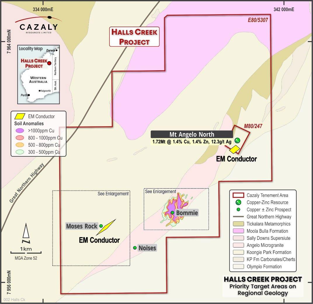
Moses Rock EM conductor
Three holes were drilled for 654m to test a modelled EM conductor located at Moses Rock 5km to the southwest of the Mount Angelo North Cu Ag Zn resource (Figure 2). The EM conductor was modelled ≈100m below surface for a strike distance of ≈300m, dipping steeply towards the southeast (Figure 3). Drilling intersected a narrow sulphidic zone with up to 80% pyrrhotite + pyrite from 212m to 214m down hole. The sulphidic intersection coincided with the position of the modelled conductor plate, however no anomalous assay results were reported.


Bommie Prospect - porphyry copper deposit
16 holes were drilled for 3,395m to test the continuity of broad copper intercepts across the Bommie Prospect on an approximate 100m x 100m grid (Figure 4). The Bommie Prospect is located 2.5km southwest of Mount Angelo North (Figure 2) and is interpreted as a large low grade porphyry copper system with significant drill intercepts as shown in Figure 4 & 5. Analytical results, sampling techniques and data collection are detailed in Appendix 1. Broad copper intercepts in recent drilling across the Bommie prospect include:

• 110m @ 0.4% Cu from surface in HCRC0065
o incl 4m 1.1% Cu from 78m
• 126m @ 0.3% Cu from 54m in HCRC0067
• 114m @ 0.3% from 2m in HCRC0077
o incl 4m @ 1.1% Cu from 46m
• 102m @ 0.3% Cu from surface in HCRC0079
• 100m @ 0.3% Cu from surface in HCRC0080
• 78m @ 0.3% Cu from 72m in HCRC0074
o Incl 2m @ 1.1% Cu from 78m
The section line A A’ shown in Figure 4 is displayed as a cross section in Figure 5 and illustrates the distibution of copper mineralisation across the deposit from south to north. Copper intercepts show some variability in thickness with higher grades occuring at the northern end of the deposit. Elevated copper grades generally coincide with >3% sulphides. Preliminary assessment of multielement geochemical data suggests copper has a positive correlation with silver Assessment of multielement geochemical data is ongoing in order to better characterise this unusual Proterozoic porphyry copper deposit.
Figure 5. Bommie Section illustrates broad copper intercepts calculated using a 0.1% Cu lower cut and 4m internal dilution.
Cazaly’s Managing Director Tara French commented “We are pleased to see broad intercepts of copper mineralisation at the Bommie Prospect, with over 100m of mineralisation extending from surface We look forward to receiving the maiden resource estimation next month and are further encouraged by the current mineralisation envelope, which is open to the north and west of existing drilling, indicating further growth potential of this copper deposit.”
French (Managing Director) / Mike Robbins (Company Secretary)
ACN 101 049 334 Tel:
E: admin@cazalyresources.com.au Website: www.cazalyresources.com.au
Competent Persons Statement
The information contained herein that relates to Exploration Results is based upon information compiled or reviewed by Mr Don Horn, who is an employee of the Company. Mr Horn is a Member of the Australasian Institute Geoscientists and has sufficient experience which is relevant to the style of mineralisation and type of deposit under consideration and to the activity which they are undertaking to qualify as a Competent Persons as defined in the 2012 Edition of the ‘Australasian Code for Reporting of Exploration Results, Mineral Resources and Ore Reserves’. Mr Horn consents to the inclusion of his name in the matters based on the information in the form and context in which it appears.

Forward Looking Statement
This ASX announcement may include forward looking statements. Forward looking statements include, but are not limited to, statements concerning Cazaly’s planned exploration program(s) and other statements that are not historical facts. When used in this document, the words such as "could," "plan," "estimate," "expect," "intend," "may”, "potential," "should," and similar expressions are forward looking statements. Although Cazaly Resources believes that its expectations reflected in these forward looking statements are reasonable, such statements involve risks and uncertainties and no assurance can be given that actual results will be consistent with these forward looking statements. The forward looking statements in this announcement reflect views held only as at the date of this announcement.
APPENDIX 1 – Moses Rock and Bommie RC drilling results and details
Drillhole collar locations all co ordinates in MGA94, zone 52.
Hole number Northing Easting Elevation Dip Azimuth Max Depth Prospect
HCRC0062 7957751 336130 410 65 315 234 Moses Rock
HCRC0063 7957734 336145 410 60 315 96 Moses Rock
HCRC0064 7957721 336100 411 70 315 324 Moses Rock
HCRC0065 7958353 338276 428.4 50 270 174 Bommie
HCRC0066 7958447 338252 427.2 60 270 48 Bommie
HCRC0066A 7958446 338248 427.2 60 270 174 Bommie
HCRC0067 7958543 338249 426.3 60 270 180 Bommie
HCRC0068 7958547 338559 427.2 60 270 180 Bommie HCRC0069 7958640 338597 426.9 60 270 180 Bommie
HCRC0070 7958643 338245 427.9 60 270 180 Bommie
HCRC0071 7958644 338381 427.9 60 270 180 Bommie
HCRC0072 7958741 338328 426.4 60 270 150 Bommie
HCRC0073 7958746 338450 427.2 60 270 192 Bommie
HCRC0074 7958736 338575 423.1 60 270 186 Bommie
HCRC0075 7958639 338464 428.8 60 270 210 Bommie HCRC0076 7958540 338455 431.3 60 270 180 Bommie HCRC0077 7958440 338390 430.8 60 270 264 Bommie
HCRC0078 7958540 338330 429.9 60 270 354 Bommie
HCRC0079 7958338 338370 431.8 60 270 354 Bommie
HCRC0080 7958337 338438 430 90 0 257 Bommie
0.02 0.4 30.25 6.32
1.0 25.75
0.3 53.36 9.00
0.02 0.3 7.59 2.10
0.02 0.3 3.56 2.00
0.01 0.3 12.24 3.10
0.01 0.3 47.58 3.56
0.04 0.3 18.08 5.15
0.02 0.3 17.19 9.70
0.02 0.3 12.82 4.69
0.01 0.3 4.51 9.35
0.02 0.3 15.89 5.21
0.01 0.3 19.81 3.70
0.3 15.48 4.62
0.01 0.3 20.29 5.30
Hole_ID mFrom mTo Interval Ag ppm Au ppm Cu % Mo ppm Sn ppm W ppm
HCRC0069 130 144
HCRC0069 168 180
2.85 0.01 0.4 19.15 5.07 5.47
1.26 0.02 0.3 116.17 5.62 6.67
HCRC0070 6 8 2 1.31 0.01 0.3 4.10 7.00 1.32
HCRC0070 48 50 2 1.84 0.04 0.3 15.13 4.20 8.56
HCRC0070 82 84 2 0.71 0.01 0.3 16.53 3.70 2.21
HCRC0070 106 168 62 0.84 0.01 0.4 9.56 4.03 5.62
HCRC0071 110 120 10 1.50 0.01 0.3 24.04 3.94 8.12
HCRC0071 120 126 6 1.65 0.01 0.3 29.65 5.27 6.60
HCRC0071 136 140 4 1.94 0.02 0.3 94.87 4.15 10.50
HCRC0071 158 164 6 2.37 0.03 0.3 22.89 3.00 8.97
HCRC0071 170 180 10 3.28 0.02 0.3 10.78 2.80 6.44
HCRC0072 44 66 22 2.90 0.03 0.4 16.48 3.66 4.65
HCRC0072 100 102 2 0.55 0.01 0.4 13.46 8.90 7.81
HCRC0072 112 114 2 0.74 0.01 0.4 10.79 11.30 7.42
HCRC0073 12 16 4 1.50 0.02 0.3 7.84 8.50 4.09
HCRC0073 70 72 2 2.72 0.03 0.3 20.16 2.80 5.51
HCRC0073 96 104 8 1.23 0.01 0.3 14.84 3.30 6.10
HCRC0073 144 150 6 1.47 0.02 0.3 12.43 2.97 7.59
HCRC0074 18 36 18 3.20 0.01 0.3 5.24 9.01 4.03
HCRC0074 72 150 78 2.42 0.01 0.3 32.80 7.84 6.80 including 78 80 2 5.81 0.03 1.0 32.82 18.40 18.31
HCRC0074 180 186 6 2.72 0.01 0.3 11.54 4.77 7.25
HCRC0075 6 16 10 2.34 0.02 0.3 8.25 2.32 3.24
HCRC0075 60 62 2 2.58 0.01 0.3 10.89 1.90 5.76
HCRC0075 142 146 4 1.60 0.03 0.3 159.18 3.65 7.67
HCRC0076 28 40 12 1.16 0.01 0.3 22.77 3.13 6.84
HCRC0077 2 116 114 1.39 0.02 0.3 24.25 2.21 3.50 including 46 50 4 4.01 0.13 1.1 12.83 3.30 7.56 HCRC0077 238 240 2 2.77 0.01 0.5 98.98 11.90 2.24 HCRC0077 252 256 4 2.23 0.02 0.4 97.66 15.50 4.74
HCRC0077 262 264 2 1.48 0.01 0.3 18.38 21.00 2.73
HCRC0078 2 8 6 1.15 0.01 0.3 8.65 3.53 1.81 HCRC0078 18 22 4 0.76 0.01 0.3 9.81 3.30 5.05
HCRC0078 38 44 6 0.69 0.01 0.3 8.76 2.47 6.92
HCRC0078 74 156 82 1.74 0.01 0.3 54.07 2.90 2.35
HCRC0078 174 180 6 5.71 0.02 0.4 26.99 2.33 3.49
HCRC0078 218 238 20 1.87 0.02 0.3 70.01 1.67 3.76
HCRC0078 302 306 4 1.64 0.01 0.4 14.74 5.25 1.54
HCRC0079 0 102 102 1.87 0.01 0.3 27.70 4.77 12.88 including 16 18 2 2.86 0.01 1.1 22.82 8.80 20.16
HCRC0079 110 114 4 1.57 0.01 0.3 17.04 6.10 1.85
HCRC0079 134 150 16 1.69 0.01 0.3 53.46 5.00 11.49
HCRC0079 172 178 6 1.44 0.01 0.3 152.57 5.57 5.72
Hole_ID mFrom mTo
HCRC0079 182 184
HCRC0079 214 218
0.85 0.02 0.4 333.54 6.20 1.75
1.56 0.01 0.4 346.73 7.65 2.26
HCRC0079 260 264 4 1.13 0.01 0.3 30.03 4.35 3.69
HCRC0079 314 322 8 0.70 0.02 0.3 25.68 4.58 2.48
HCRC0079 322 326 4 0.95 0.01 0.3 40.81 3.40 2.66
HCRC0079 336 340 4 0.73 0.01 0.3 66.13 2.60 1.98
HCRC0080 0 100 100 1.80 0.01 0.3 42.15 5.38 5.76
HCRC0080 122 136 14 1.84 0.02 0.3 12.77 4.74 3.24
HCRC0080 138 162 24 2.83 0.02 0.3 37.71 2.83 5.62
HCRC0080 188 190 2 3.45 0.03 0.4 613.41 8.90 4.57
HCRC0080 192 200 8 1.40 0.04 0.3 22.12 14.00 39.58
JORC Code, 2012 Edition – Table 1
Section 1 Sampling Techniques and Data
Criteria
JORC Code explanation
Sampling techniques Nature and quality of sampling (e.g. cut channels, random chips, or specific specialised industry standard measurement tools appropriate to the minerals under investigation, such as down hole gamma sondes, or handheld XRF instruments, etc). These examples should not be taken as limiting the broad meaning of sampling.
Include reference to measures taken to ensure sample representivity and the appropriate calibration of any measurement tools or systems used.
Drilling techniques
Aspects of the determination of mineralisation that are Material to the Public Report. In cases where ‘industry standard’ work has been done this would be relatively simple (e.g. ‘reverse circulation drilling was used to obtain 1 m samples from which 3 kg was pulverised to produce a 30 g charge for fire assay’). In other cases more explanation may be required, such as where there is coarse gold that has inherent sampling problems. Unusual commodities or mineralisation types (e.g. submarine nodules) may warrant disclosure of detailed information.
Drill type (e.g. core, reverse circulation, open hole hammer, rotary air blast, auger, Bangka, sonic, etc) and details (e.g. core diameter, triple or standard
Commentary
The Moses Rock and Bommie prospects have been sampled using Reverse Circulation (RC) drill holes. Holes were drilled on various grid spacings angled 50° to 90° to varying azimuths designed to drill perpendicular to the interpreted strike of mineralisation.
Collar positions were located with a handheld GPS with an expected accuracy of ± 3m. Hole azimuth was measured with a geological compass at the collar location.
Down hole surveys were taken with a Axis Gyro tool every 30m down hole.
1 industry prepared independent base metal multielement standard, 1 blank sample and 1 field duplicate sample were inserted per every 20 samples submitted.
Moses Rock RC samples were collected at 4 metre composite intervals by a spearing sample 1 piles to make up a total weight of approximately 3kg per sample submitted.
Bommie RC samples were collected at 2 metre composited intervals by rig mounted cone splitter to make up a total weight of approximately 3kg per sample submitted.
All RC samples were sent to the accredited Jinning laboratory in Perth for sorting, crushing, pulverization and analysis by fire assay (Au) and four acid digest (multielement suite) methods.
Samples from RC were considered representative and appropriate for the material sampled.
Reverse circulation drilling employing a face sampling hammer was used for all drilling at Moses Rock and Bommie.
Criteria
Drill sample recovery
Logging
JORC Code explanation Commentary
tube, depth of diamond tails, face sampling bit or other type, whether core is oriented and if so, by what method, etc).
Method of recording and assessing core and chip sample recoveries and results assessed.
Sample recovery was estimated visually and by using a spring scale to check sample weights were sufficient. Over 99% of samples were considered to have excellent recovery and over 99% of samples were dry. Small amounts of poor recovery are noted while collaring the hole and some minor wet samples were noted where there was high water influx from aquifers.
Sub sampling techniques and sample preparation
Measures taken to maximise sample recovery and ensure representative nature of the samples.
The RC rig cyclone and splitter were cleaned throughout each drill hole, between samples and after drilling each rod. Thorough cleaning after intervals of significant water was also done. RC sample recovery was visually assessed with recovery, moisture and contamination recorded into a logging template. Sample weights were regularly checked using a spring scale.
Whether a relationship exists between sample recovery and grade and whether sample bias may have occurred due to preferential loss/gain of fine/coarse material.
Whether core and chip samples have been geologically and geotechnically logged to a level of detail to support appropriate Mineral Resource estimation, mining studies and metallurgical studies.
Whether logging is qualitative or quantitative in nature. Core (or costean, channel, etc) photography.
The total length and percentage of the relevant intersections logged.
If core, whether cut or sawn and whether quarter, half or all core taken.
If non core, whether riffled, tube sampled, rotary split, etc and whether sampled wet or dry.
Over 99% of RC sample recoveries were good, no bias is expected for all drilling completed.
All drill chips were geologically logged on site by geologists following the CAZ logging scheme. With all recorded information loaded to a database and validated.
Logging is qualitative with colour, lithology, texture, mineralogy, mineralization, alteration and other features. Indicative geochemical measurements using a Niton XRF were also recorded.
All drill holes were logged in full.
N/A
Moses Rock: 1 metre RC drill samples fall through a cone splitter directly below the rig mounted cyclone. A 2‐3 kg sample is collected in a pre‐numbered calico bag and lined up in rows with the corresponding bulk 1 metre sample pile collected by a bucket. If wet samples are collected during RC drilling this is recorded and loaded to a database. Samples are composited to 4m intervals with a PVC spear at the discretion of the logging geologist
Bommie: 1 metre RC drill samples fall through a cone splitter directly below the rig mounted cyclone. A 2‐3 kg 2m composite sample is collected in a pre numbered calico bag and lined up in rows with the corresponding bulk 1 metre sample pile collected by a bucket. If wet samples are collected during RC drilling this is recorded and loaded to a database. All
Criteria
Quality of assay data and laboratory tests
JORC Code explanation Commentary
2m composite calico bags were submitted for analysis.
Verification of sampling and assaying
For all sample types, the nature, quality, and appropriateness of the sample preparation technique.
Quality control procedures adopted for all sub sampling stages to maximise representivity of samples.
Measures taken to ensure that the sampling is representative of the in situ material collected, including for instance results for field duplicate/second half sampling.
Whether sample sizes are appropriate to the grain size of the material being sampled.
All drill samples are dried, crushed and pulverised to achieve an average of 85% passing 75µm and all samples are considered appropriate for this technique
Duplicate field sample composites were collected in RC drilling at the rate of 1:20.
Appropriate sampling protocols were used during RC composite sampling. This included spear collection at various angles through bulk 1 metre sample piles to maximize representivity.
Sample sizes (2kg to 3kg) are considered to be of a sufficient size to accurately represent any base metal mineralisation (massive and disseminated sulphides and associated supergene enrichment).
Field duplicates have been collected to ensure monitoring of the sub sampling quality.
The nature, quality and appropriateness of the assaying and laboratory procedures used and whether the technique is considered partial or total.
Samples have been sent for analysis to the Jinning laboratory in Perth (a commercial accredited independent laboratory). All RC samples will be analysed by:
• Fire Assay using a 50g charge finished by ICP AAS to analyze for Au.
• Four Acid Digest to analyze a suite of elements with an ICP OES/MS finish.
For geophysical tools, spectrometers, handheld XRF instruments, etc, the parameters used in determining the analysis including instrument make and model, reading times, calibrations factors applied and their derivation, etc.
Nature of quality control procedures adopted (e.g. standards, blanks, duplicates, external laboratory checks) and whether acceptable levels of accuracy (i.e. lack of bias) and precision have been established.
The verification of significant intersections by either independent or alternative company personnel.
The use of twinned holes.
Documentation of primary data, data entry procedures, data verification, data storage (physical and electronic) protocols.
XRF measurements have been taken on 1m drill spoil piles to give a rough indicative reading for Cu Mo at Bommie. These results are not considered material and results from this will not be released on the ASX.
Field duplicate samples and standards were submitted with each sample batch at a rate of 1:20. The laboratory will insert its own standards, blanks, and duplicate samples to ensure results are within tolerable limits.
All data has been checked internally by senior CAZ staff
N/A
Field data is collected using an excel spreadsheet with internal validation on a Toughbook computer. Validation checks are also used when loading the data to a company MX Deposit database.
Discuss any adjustment to assay data. No adjustments are made to assay data
Accuracy and quality of surveys used to locate drill holes (collar and down hole surveys), trenches, mine
Collar positions were located with a handheld GPS (+3m). Down hole surveys were taken with a Axis
Criteria
JORC Code explanation Commentary
Location of data points workings and other locations used in Mineral Resource estimation.
Gyro tool every 30m down hole. Prior to resource estimation collar positions will be surveyed by a licenced surveyor to ensure accurate data location.
Specification of the grid system used. All co ordinates collected are in GDA94 MGA Zone 52
Quality and adequacy of topographic control. The topographic surface is determined from pre existing digital elevation models and DGPS survey data.
Data spacing and distribution Data spacing for reporting of Exploration Results. Holes were drilled on various grid spacings angled 50° to 90° to varying azimuths designed to drill perpendicular to the strike of mineralisation wherever possible due to drill access.
Whether the data spacing and distribution is sufficient to establish the degree of geological and grade continuity appropriate for the Mineral Resource and Ore Reserve estimation procedure(s) and classifications applied.
The data spacing and distribution is considered sufficient to demonstrate spatial and grade continuity of the mineralisation at the Bommie Prospect to support the definition of an Inferred Mineral Resources under the 2012 JORC code once all other modifying factors have been addressed.
Whether sample compositing has been applied. Moses Rock: All samples are collected at 4m intervals. Samples are composited via PVC spear to 4m at the direction of the geologist.
Bommie: All samples are collected at 2m intervals directly from the rig mounted cone splitter.
Orientation of data in relation to geological structure
Whether the orientation of sampling achieves unbiased sampling of possible structures and the extent to which this is known, considering the deposit type.
Drilling on all projects is orientated to best suit the mineralisation to be closely perpendicular to both the strike and dip of the mineralisation. Intercepts are close to true width in most cases. Exceptions are where deep creeks have not allowed for clearing to allow optimal placement of a drill rig in a small number of holes.
If the relationship between the drilling orientation and the orientation of key mineralised structures is considered to have introduced a sampling bias, this should be assessed and reported if material.
Sample security The measures taken to ensure sample security.
It is not believed that drilling orientation has introduced a sampling bias.
Samples are securely sealed and stored onsite, until delivery to Perth laboratories via contract freight Transport. Chain of custody consignment notes and sample submission forms are sent with the samples. Sample submission forms are also emailed to the laboratory and are used to keep track of the sample batches.
Audits or reviews
The results of any audits or reviews of sampling techniques and data.
No external audits on sampling techniques and data have been completed. A review of QAQC data will be carried out by company geologists.