BLDG51849 Policy & Guidlines: Government, Urban & Suburban Municipalities
Major Project – Implementation Document

 By: Somdat T, Merin J, Prakash D & Navleen K
Content
1.0 Introduction & Overview
1.1 Background
1.2 Location
1.3 Purpose of Design Guidelines
1.4 Guiding Principles
2.0 Context
2.1 Exisiting Site Conditions
2.2 Exisiting Views & Vistas
3.0 Public Realm - Parks & Open Spaces
3.1 Guidelines
3.2 Parks & Open Spaces
3.3 Parks & Open Space Plan
4.0 Pedestrain Realm - Streets & Blocks
4.1 Blocks
4.2 Nodes
4.3 Streetscapes
5.0 Mobility System
5.1 Mobility Network
5.2 Public Realm Elements
5.3 Parking
6.0 Site Organization
6.1 Building Placement
6.2 Frontages
6.3 Setbacks
7.0 Built Form Massing & Typologies
7.1 Mid Rise Built Form
7.2 Low Rise Built Form
7.3 High Rise Built Form
7.4 Office & Commercial Built Form
8.0 Sustainability
8.1 Sustainable Practices
8.2 implmenation Stragegies

1.0 Introduction & Overview
1.1 Background
1.0 Introduction & Overview
1.2 Location

The evolution of any project goes a long way when it comes to how the area looked before and what it can look like after, even after different iterations on the overall site. Currently, Port Credit was mainly a place where it was used for “Boaters” but as the area had sort of died down it needed a revamp when it came to giving that area a new purpose. Giving a place a new purpose does bring people together since it’s something fresh in a new environment.. Here at S.P.A.C.E.
We originally looked at the site and thought to ourselves what can be added to this space that would get people to visit or even live here. There have been many revisions of how the master plan of the site would have come out but with these revisions of the evolution process, we analyzed that people would like a mix-use area that had more than one purpose which would be suitable for everyone. In the first few revisions of this project, there have been changes to the layout of buildings and how the spaces would have connected with the use of a network system that made sense.
Then we took a look at precedent studies that gave inspiration to adding different elements that would make the space stand out, this would be the protruded deck that is in the current park space of the existing site. Building height design was another part that had many changes along the way which had to suit the overall look and feel of the site along with where they were placed and what function it had to the public. Overall the evolution of this project had its ups and downs when it came to looking at the overall pros and cons of what changed and what didn’t change but the pros will always be more impactful than one small con. It took a lot of back and forth with what we have proposed with S.P.A.C.E but it made it even better as an overall outcome. Looking back at the existing site to what is being proposed there are a lot of changes that will happen which will give area designated uses.
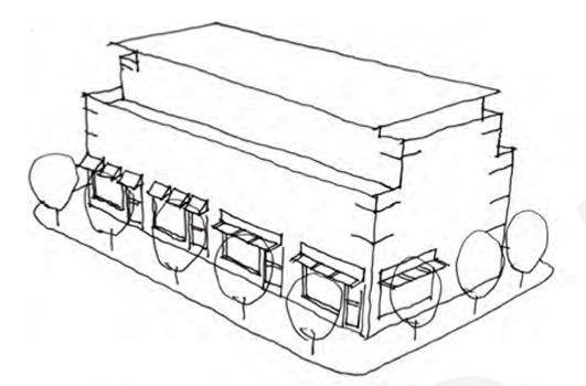
Fg. Existing Site Plan
1.0 Introduction & Overview
1.3 Purpose of Design Guidelines
Design guidelines serve as a set of principles, recommendations, and best practices that help individuals and teams create consistent, effective, and user-friendly designs. These guidelines are created to ensure that design work aligns with the goals and values of a project, organization, or industry. The primary purposes of design guidelines include:
Consistency: Design guidelines establish a cohesive and unified visual and user experience across different parts of a product, platform, or brand. Consistency is important for building brand recognition, reducing confusion among users, and creating a seamless experience.
Communication: Guidelines serve as a common reference point for designers, developers, and other stakeholders. Clear guidelines help facilitate communication between team members, ensuring that everyone understands the design intent and requirements.
Scalability: As projects grow in complexity or size, design guidelines help maintain a coherent design approach. New team members can quickly familiarize themselves with the design principles, enabling them to contribute effectively.
Adaptation: Design guidelines often include considerations for different devices, screen sizes, and platforms. This allows designs to adapt to various contexts while maintaining their core visual and functional attributes.
In essence, design guidelines help create a bridge between creativity and practicality. They offer a structured framework that guides design decisions, leading to designs that are functional, aesthetically pleasing, and aligned with the broader goals of a project or organization.
1.0 Introduction & Overview
1.4 Guiding Principles & Objectives
The proposal contributes to the achievement the vision, by providing a well-designed new building and accompanying landscaping on the Mississauga waterfront, stitching the site into the waterfront landscape. The future building to be facilitated through the proposed amendments will be suitably setback from Lake Ontario, with the relocation of as-of-right density to a slimmer and more articulated massing with an overall more sensitive built form response to the waterfront context. This more sculptural building will deliver an appropriate density for the surrounding context, responding to the evolving neighbourhood form and allowing the preservation of established, stable neighbourhoods where growth is not desired.
Compacted & Connected Communities:
Complete Communities: By providing a varied selection of amenities, including shops, restaurants, entertainment opportunities, and services, the space can work to become a complete community. Residents would be able to get whatever they require in the area, resulting in a compact and connected community.
Local entrepreneur & Job Opportunities:
The area can support the economic growth of the region by involving neighborhood businesses and community organizations, offering job opportunities, and collaborating on planned events, workshops, and volunteer programs to contribute to social development.
Adaptive Infrastructure:
The creation of flexible infrastructure that can take into account the community's changing needs and preferences can be the main goal of the proposal.
2.0 Context 2.0 Context


2.1


3.0 Public RealmParks & Open Spaces
3.1 Guidelines
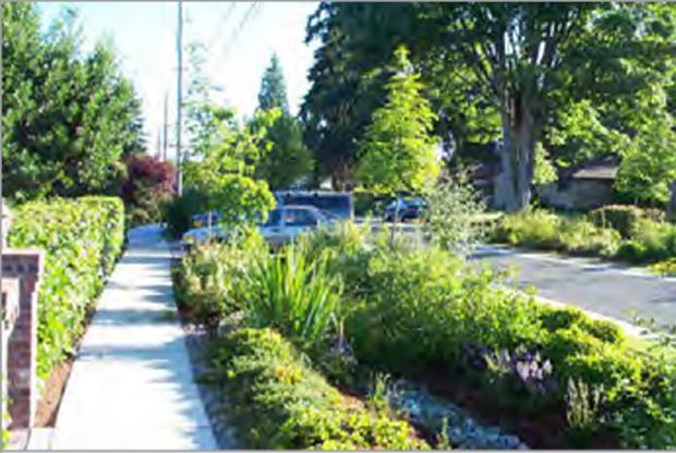
The Port Credit Node precincts, particularly the Central Residential Precinct and the Riverside Precinct are characterized by well landscaped front yards and mature trees.
The landscape area is defined as any outdoor area on a lot, located at grade, including the landscaped buffer area, that is suitable for the growth and maintenance of grass, flowers, shrubs, trees and other landscape features, and may include walkways, berms, retaining walls and outdoor amenity areas, but shall not include, driveways, aisles, ramps or internal roads, parking areas whether surfaced or not, curbs, any open space beneath or within any building, structure or any exterior garbage storage or handling area.

• A minimum of 30 % landscape area is required for all sites within the Central Residential Precinct, the Riverside Precinct and the Harbour Mixed Use Precinct. This is to ensure that all lots can achieve a minimum buffer to adjacent uses; ensure that the existing context which contains well landscaped front yards, particularly on high density sites, can be achieved; to ensure sustainable measures can be attained; and to ensure overdevelopment of sites does not occur.


• It will also help protect views to Lake Ontario through future development of sites along the 30% landscape area for a small lot on a 40 m x 45 m lot size produces the minimum landscape buffer requirement of 4.5 m on the rear and side lot line. It does not maintain the required front and exterior side yard setback from the front property line.
The landscape area should achieve a row of coniferous trees with shrubs and/’or perennial plantings to provide a natural visual buffer between the two uses.
• In the Mainstreet Precinct, where development is intended to create a compact commercial mainstreet, no minimum landscape area will be required, however, a minimum 4.5 m landscape buffer is required when a mixed use zone abuts a residential zone.
• A landscape buffer is defined as a continuous, open, unobstructed width of land substantially parallel to and adjoining a lot line that is intended for the growth and maintenance of plant material including trees, shrubs and other landscape features such as retaining walls
3.0 Public RealmParks & Open Spaces
3.2 Parks & Open Spaces
3.0 Public RealmParks & Open Spaces
3.3 Parks & Open Spaces Plan


4.0 Pedestrian RealmStreets & Blocks
4.1 Blocks

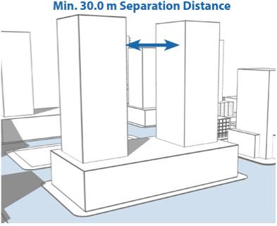
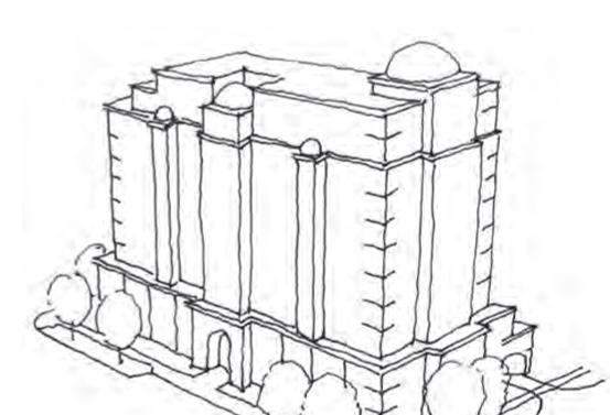
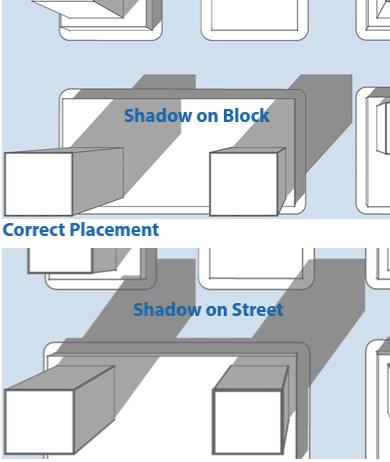
The proposal seeks to shift massing from the lower portion of the building, to a more refined and slender tower form. This will in turn allow for a more articulated building that presents an interesting and more slender form, in turn increasing opportunities for the protection of key public views and outlook for future residents. The slender form of the tower will also minimize shadowing affects of new development on the site. Compared to the as-of-right outcome, the shadow cast by the new building will be more slender and faster moving.

4.0 Pedestrian RealmStreets & Blocks

4.2 Streetscapes
5.1 Mobility Network & Paths
5.0 Mobility System
Mobility Network:
In order to promote sustainable and efficient mobility while improving the overall livability of the Port Credit area, the following guidelines are proposed for enhancing the mobility network:
Multi-Modal Connectivity: Prioritize a well-connected network that accommodates pedestrians, cyclists, public transit, and vehicles seamlessly. Ensure the design includes dedicated mainly pedestrian walkways, pedestrian trails, clearly marked and safe cycling lanes, and well-maintained roadways.


Complete Streets: Implement a "complete streets" approach to ensure that roadways are designed to accommodate all users, including pedestrians, cyclists, and public transit riders. Consider features such as wider sidewalks, landscaped buffers, and safe crosswalks.
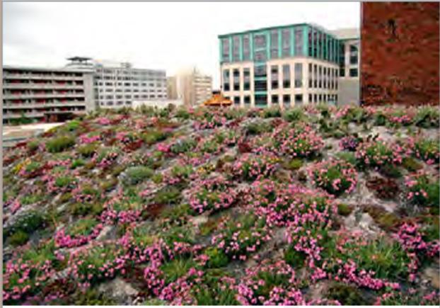
Green and Active Spaces: Incorporate green spaces, parks, and plazas along the mobility routes, encouraging community engagement and recreation. These spaces can also serve as transit waiting areas, promoting a welcoming atmosphere. The green pockets around the walking trails help pedestrians to connect with the natural environment so green pockets around the built environment are encouraged.
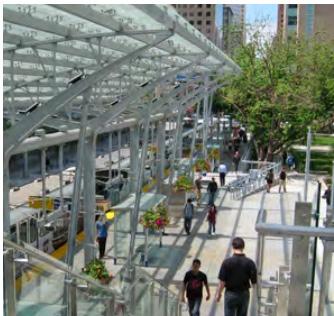
5.2 Public Realm Elements

5.0 Mobility System
5.3 Parking
Public Realm elements:
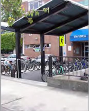
The public realm has a significant value as it pertains to the open spaces accessible to the community. These spaces encompass a range of elements, including POPS (Privately-Owned Publicly Accessible Spaces), parks, streets, plazas, open zones, walkways, and alleys. Within this framework, various components such as sidewalks, street trees, planters, eco-friendly infrastructure, street furnishings, bikeways, and bike storage spaces play a crucial role in defining the public domain's character.

As Port Credit seeks to enhance its urban landscape, the focus remains on expanding pedestrian walkways, introducing designated bike paths, and refining the conditions for planting trees. By doing so, the goal is to create an environment that not only ensures the safety and enjoyment of pedestrians but also promotes sustainable transportation alternatives. With these improvements, Port Credit aims to foster a more vibrant and accessible community, where the public domain becomes a thriving hub for social interaction, recreation, and environmentally conscious mobility.
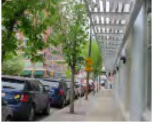
1. Sidewalks: To support pedestrian mobility minimum 2m wide sidewalk should be provided on every main street on the Port Credit Harbor marina revitalization project. The sidewalk should contain a 1m wide curb for the separation from the vehicular lane and to accommodate the streetlights and street furniture.
2. Street trees: To promote sustainability and greenery on the Port Credit, streets and the public realm should contain street trees at a minimum of each 15m to 20m intervals. The street trees should be of the species which have long trunks without branches up to a minimum of 5m so that they create a nice tree canopy on the street and give good shade to pedestrians without hindering their walk.
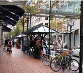
3. Street furniture: To enhance public engagement and comfort street furniture is recommended in every public realm. Street furniture should be of wood so that they do not heat extremely on a sunny day. Street furniture can be used by the public to rest during their walk and can also be used for the picnic.
4. Permeable pavement: To promote natural infiltration and reduce the impermeable surface, sidewalks, and open spaces in the public realm should be paved with permeable pavers.
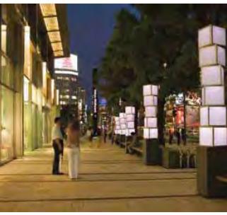
5. Streetlights: Street light helps to improve the safety and sense of security of the people who enjoy the public realm at night. Streetlights should be both for vehicular land and sidewalk for vehicles and pedestrians respectively. Streetlights should be placed at the interval of 2.5 to 3 times the height. The height for the light in pedestrian footpath and open space should be 6m to 8m whereas the light on the vehicular road should be 10m to 12m.
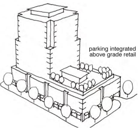
The design of parking, servicing, and loading areas is a key component in the development of sites. These areas serve a functional need but should be designed in a manner that screens fewer desirable aspects and provides highquality treatment of exposed areas while addressing the safe and efficient movement of pedestrians, cyclists, and vehicles.
Parking should be located underground, internal to the building, or at the rear of the buildings. Above-grade parking structures should be designed so that vehicles are not visible to the public and have appropriate directional signage for the structure. Service, loading, and garbage storage areas should be integrated into the building or located at the rear and screened from the public realm and adjacent residential uses.

6.0 Site Organization
6.1 Building Placement & Routes


6.3 Building Setbacks
1.Mixed Use Street Setbacks
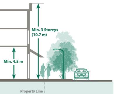
Setbacks from the property line on streets where retailing is required should typically be from 0.6 and 3.0 metres. Once the public space has reached its full potential, the precise location of new structures will be decided. For proper streetscape treatment, new development must accommodate 5.6 metres of public realm from the curb of the sidewalk or street to the face of the building.
Commercial
Uses are recommended but not required to be located on the red-hued transitional streets. Buildings should be made to be adaptable to commercial purposes when the market conditions permit.
Residential Streets
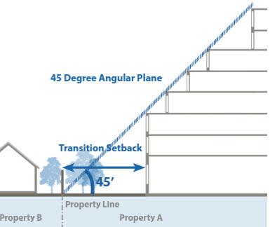
The setback to a building must be between 4.5 and 7.0 metres, depending on the nature of the nearby developments and the design of the proposed structure. The setback must ensure that there is enough suitable landscape design to blend in with the neighborhood's current character. propriate streetscape treatment can be achieved.
6.2 Frontages
Provide a continuous buildings along development blocks fronting onto ‘A’ Streets to provide continuity of built form from one property to the next

• A minimum of 90% of a property’s frontage is required to be occupied by the streetwall at the build-to line Development will be prohibited from locating curb cuts, driveways and laneways on ‘A’ Streets; A maximum of 25% (i.e. 25% of 90%) of the building frontage will be allowed to stepback to a

• maximum of 4.5 m from the build-to line to allow for articulation of the streetwall, including provision for outdoor patios, recessed entries and landscaped areas;
• Functioning main entrances to buildings will be provided on ‘A’ Streets. (Also, see Section 2.7 Ground Floor Treatment); Ground floor elevations along ‘A’ frontages will have a minimum of 60% vision glazing with views into the building; and
• Where residential uses are permitted at the ground level, special provisions will apply for the design of unit entrances and setbacks (see Section 4.10 Design for at Grade Residential Uses).