PORT FOLIOPORT FOLIO


Joseph James Luke Avellino
DOB: 02/05/2003
Third-Year Architecture Student
REACH ME AT:
+1(347)-587-9882
javellin@nyit.edu
58-17 80th Street
Middle Village, NY, 11379

Joseph James Luke Avellino
DOB: 02/05/2003
Third-Year Architecture Student
REACH ME AT:
+1(347)-587-9882
javellin@nyit.edu
58-17 80th Street
Middle Village, NY, 11379
3D MODELING / DRAFTING
AutoCAD
Revit
Rhino 7
Adobe Creative Suite
Illustrator
Photoshop
InDesign
Enscape
CONSTRUCTION REGULATIONS
NYC Zoning Resolution
NYC Building Code
VISUALIZATION
Hand Drawing
Physical Modeling
Struggles Proficient
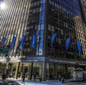
New York Institute of Technology -- 1855 Broadway, Manhattan, NY, 10023
Start Date: September 2021 || End Date: June 2026
Projected Degree: Bachelor’s of Architecture
CUMULATIVE GPA: 3.9
Dean’s List (3.5+ GPA): Fall 2021
Presidential Honor’s List (3.7+ GPA): Spring 2022, Fall 2022, Spring 2023, Fall 2023
Archbishop Molloy High School -- 8353 Manton Street, Briarwood, NY, 11435
Start Date: September 2017 || End Date: June 2021
Degree: High School Diploma
CUMULATIVE GRADE: 94.50% (Honors with Distinction)
- CAD Drafting / Project Organizer -- ACV Architecture (202 Foster Avenue)
_Drafted plans, elevations, and sections for 10+ residential projects proposed within the five NYC boroughs, predominately Brooklyn.
_Organized sheets covering various analyses of the proposed building (Energy, Mechanical, Zoning, Demolition Plans, etc.)
_Drew maximally detailed wall sections / technical callouts.
_Used the NYC Building Code and Zoning Resolution to make specific architectural decisions (permitted obstructions, fixture placement, etc.)
_Consulted the AISC Steel Construction handbook for structural design for any projects that utilized Type I, II, or III construction.
_Received an introduction to filing projects for the NYC Department of Buildings (Answering objections, requesting new BINs, etc.)
To whom it may concern-
- Emerging Ecologies -- Museum of Modern Art, 11 W 53rd Street (12.18.23)
_Learned more about the way shading strategies (greenhouses, wind catchers, etc.) make their way into passive architectural design.
_Was able to better visualize how greenery can clash with material without feeling forced or out of place.
Nice to meet you! I’m Joe Avellino, an architecture student studying at the Mahattan campus of New York Institute of Technology. To compliment my undergraduate studies, I’m seeking a position as an intern for an architectural office for 6 months minimum.
I’m very engaged in my work and am always asking questions, so I’m excited to not only contribute my own knowledge to the development of my future team, but also to learn lots from them. I’m hoping to pull my weight and share the success of the company.
I. Studio Work
- Accounting Structure
- Evolution of Spaces
- Adaptability of Concepts in Real Life
III. Visual Arts
-Hand Drawings
-Digitalized Concepts
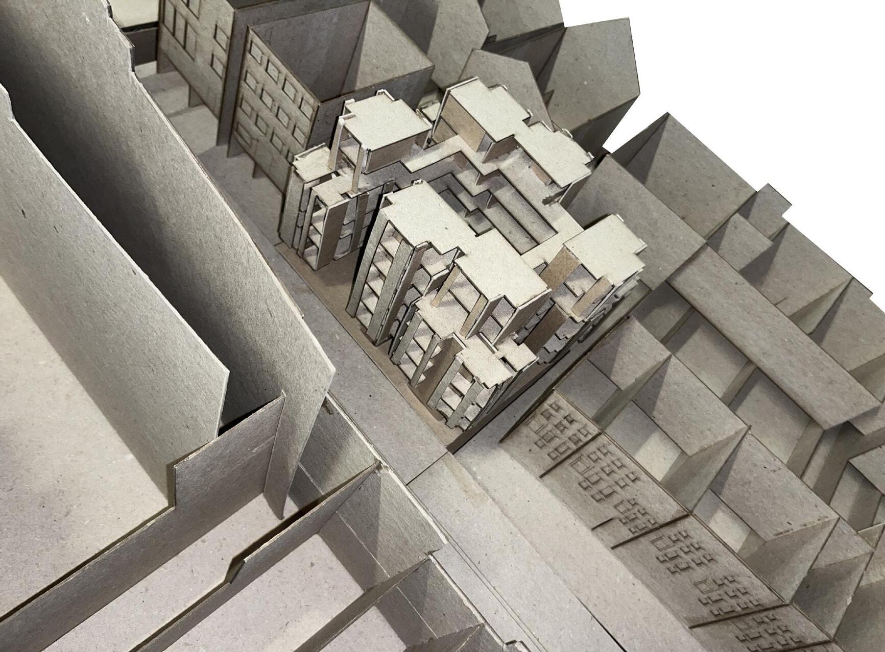
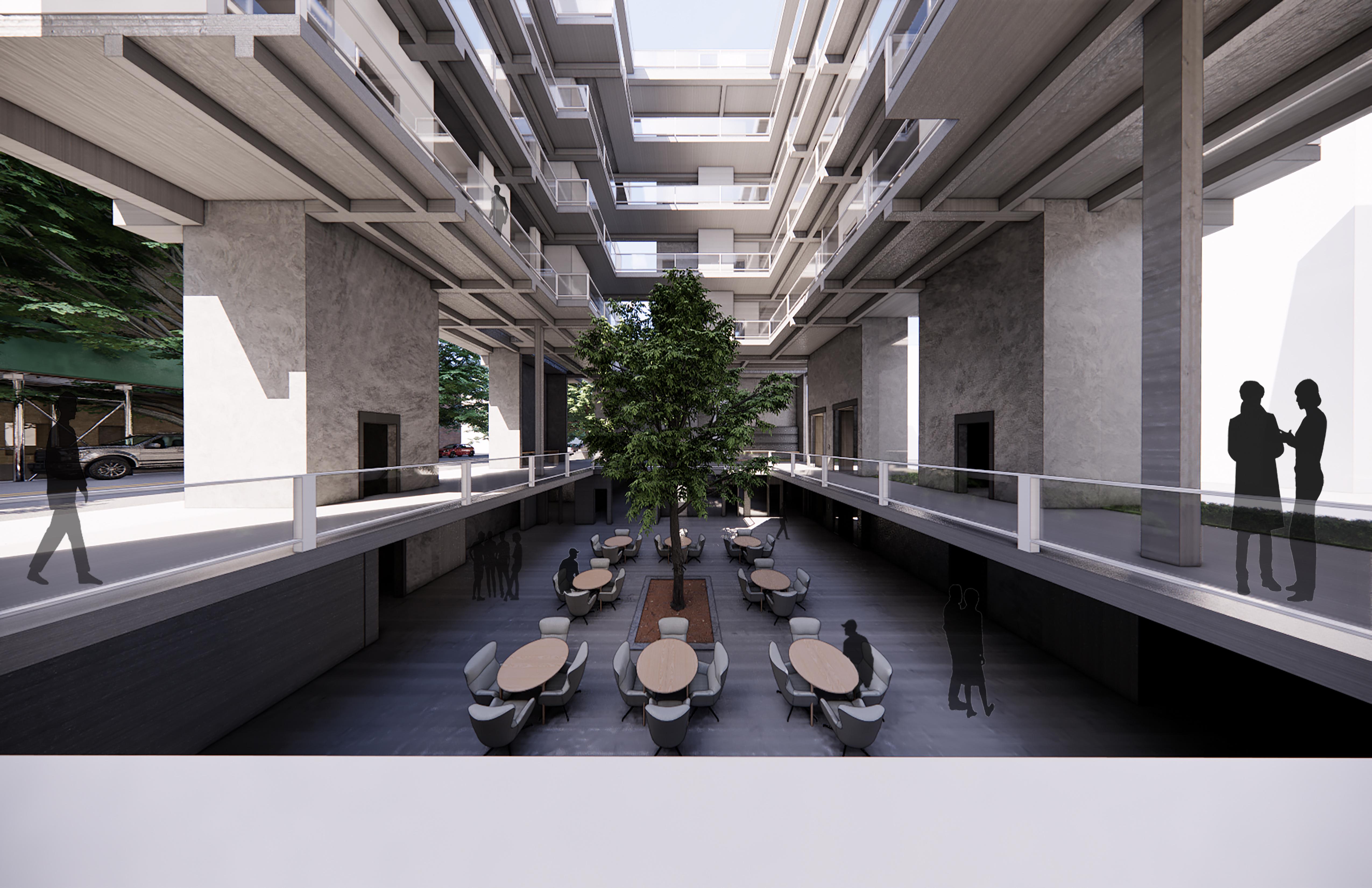
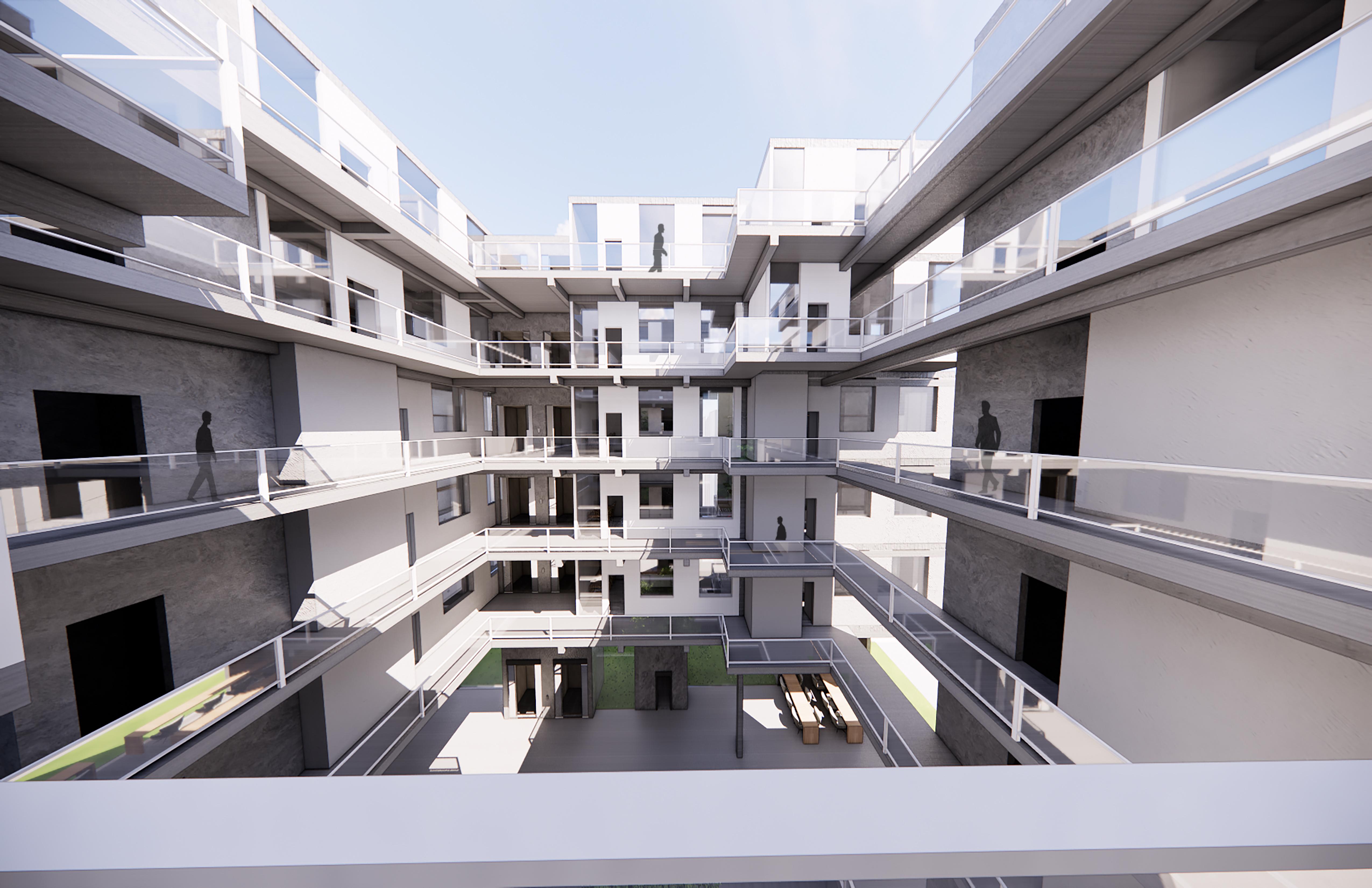
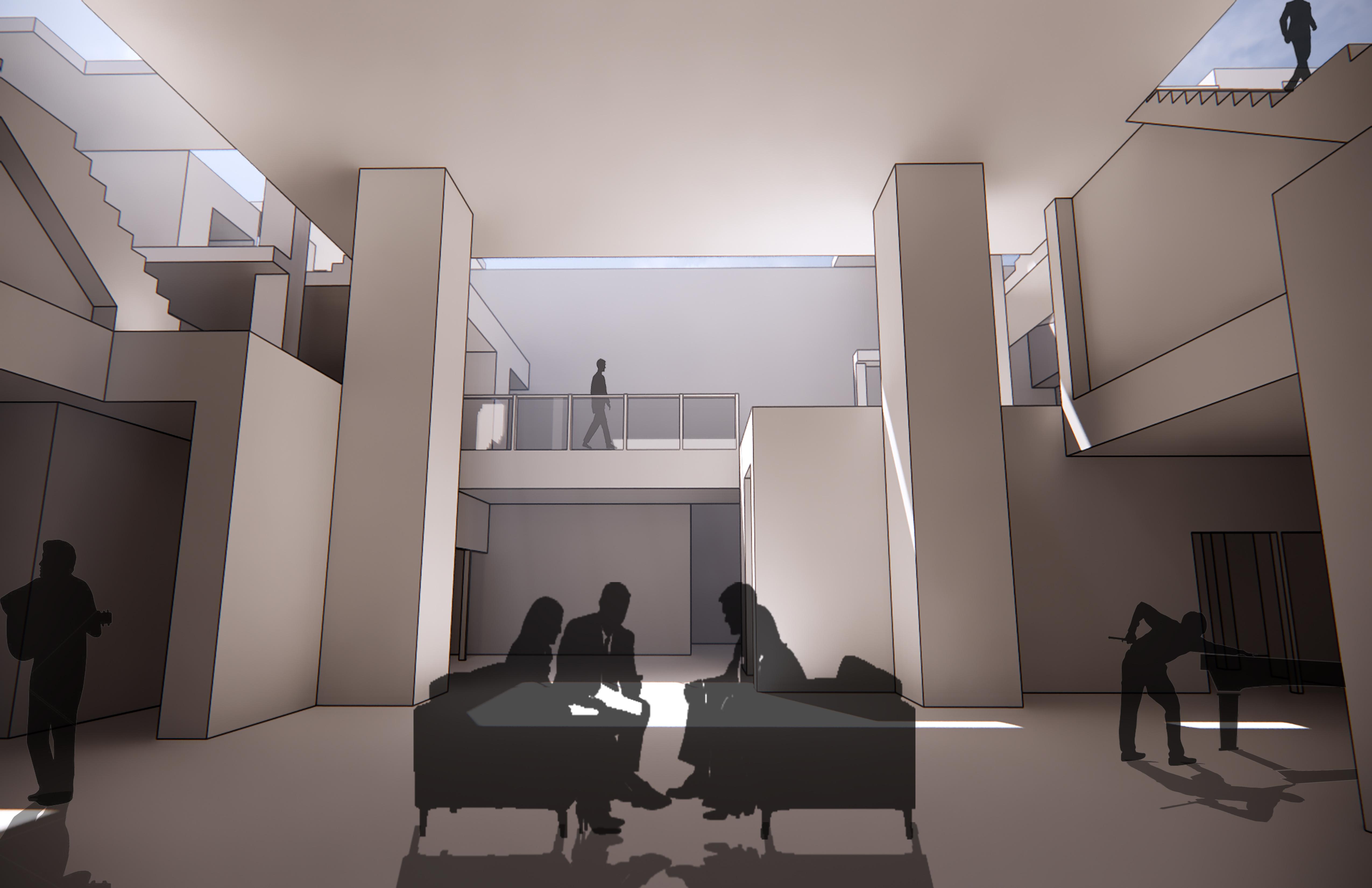
Concrete Forest
Year 3 - Fall 2023 (Architectural Design 3)
The Concrete Forest is a multi-story housing proposal located in Northern Brooklyn, specifcially at the interection between Gates and Nostrand Avenue. The goal of this semester-long project was to provide safe, immersive housing that not only flourishes with natural light and air, but also disguises itself well in the overall brownstone house setting of the neighborhood.
THICK zones will have thicker walls (1’). In these zones noises are better contained, while less outside noise will interfere with the program.
THIN zones will have thinner walls (0.5’). In these zones, it isn’t as necessary to muffle outside noise.
PUBLIC VS PRIVATE
PUBLIC spaces are shaded in red. They include living/dining and cooking/ storing spaces.
PRIVATE spaces are shaded in blue. They include resting/bathing spaces.
- CAST-IN-PLACE FLAT PLANES: Concrete molds filled in on-site. Circulation paths that connect the units on each floor are included to provide more seismic and wind resistance.
- SHEAR WALLS: Central thick zones of each studio unit + Elevator Core and Fire Stairwells
- BEAMS: Dispersed from the shear walls and extend various distances.
THICK (2’x2’): Travel shorter distances and cantilever outwards.
THIN (1’x1’): Travel longer distances and connect to other beams to transfer loads.
- COLD-FORMED STEEL: Framing for the remaining facades to prevent thr building from being unneccessarily heavy, given that the remaining facades will provide no additional structural support.
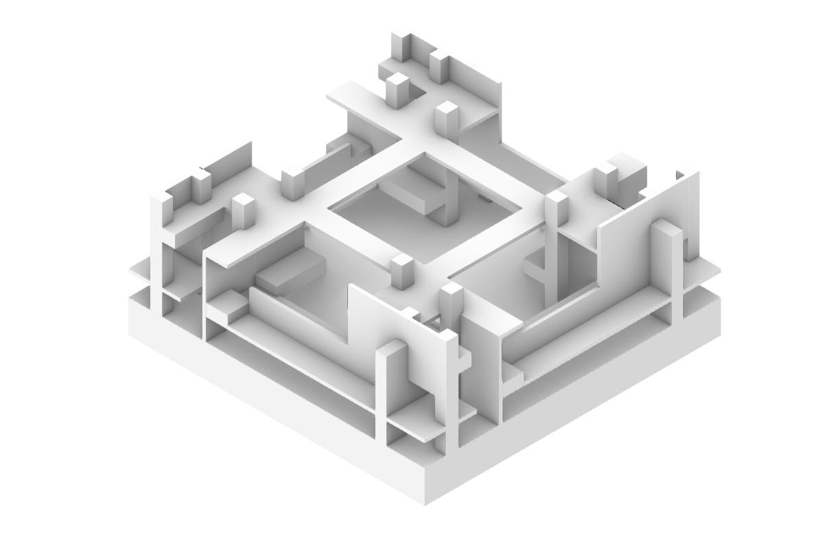
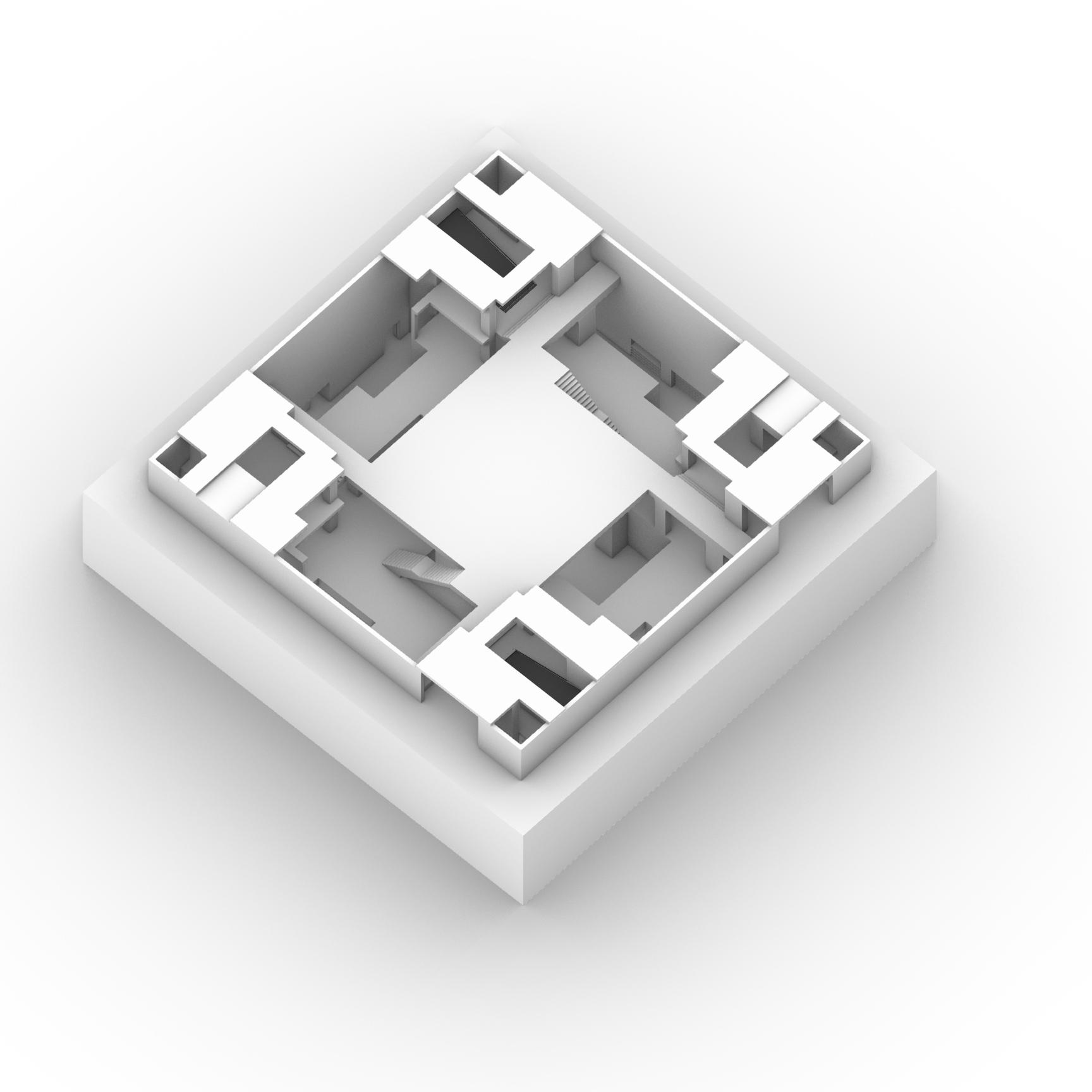
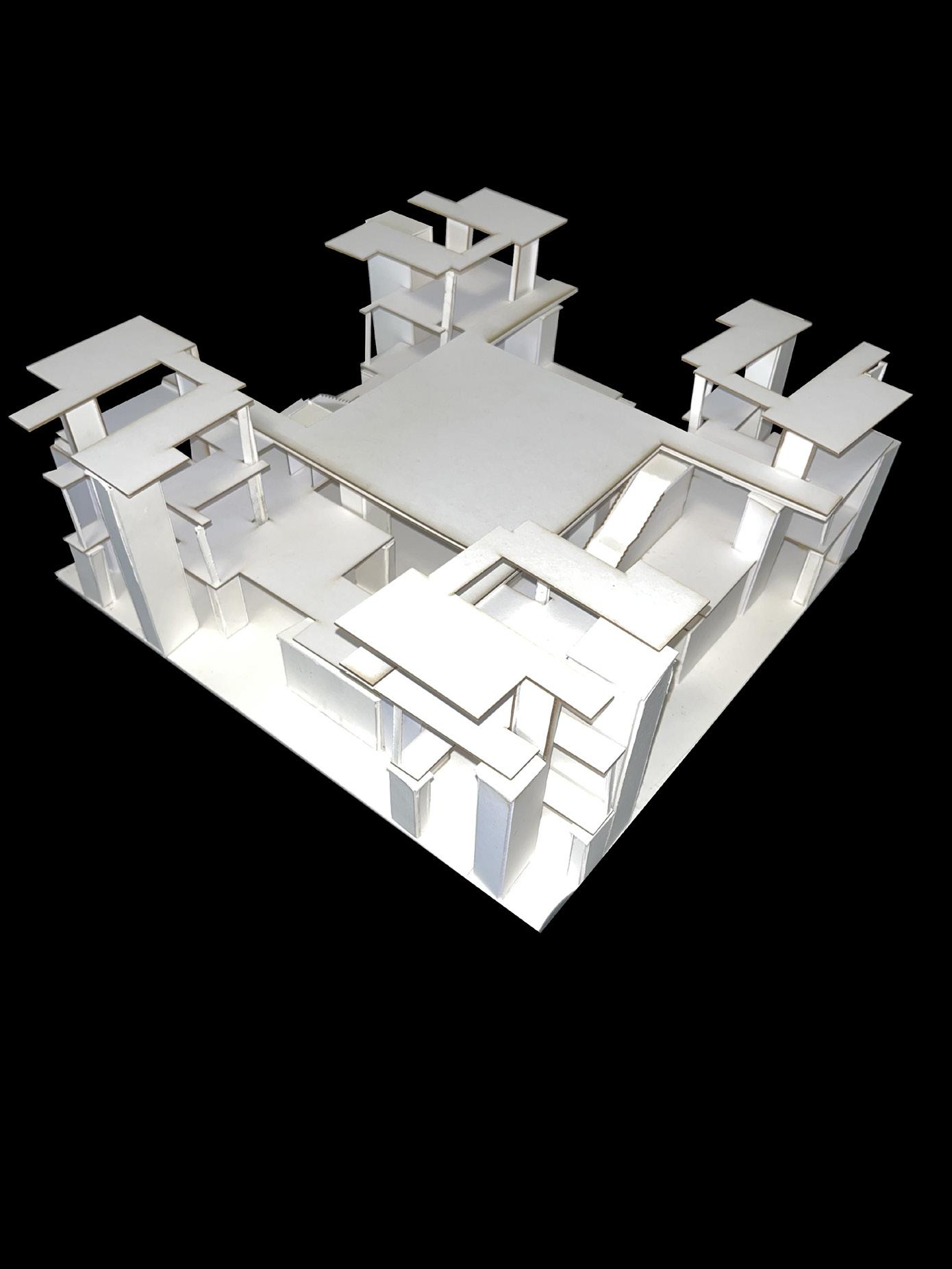
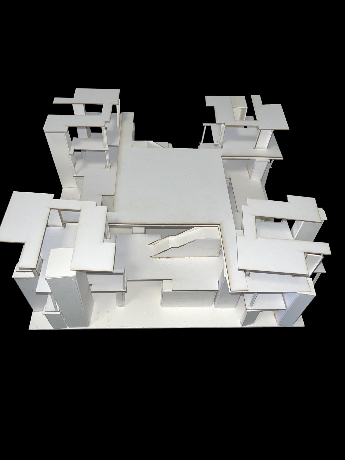
East ViewThe plans follow the first conceptual diagram: A defined central element, followed by 2 pairs of different elements in opposing quadrants, therefore defining all corners. In the plans, the central element is typically a lack thereof, or a void. The corner quadrants consist of units and fire stairwells.
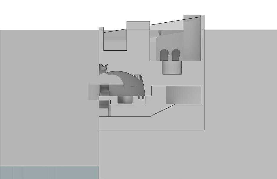
The sections follow the second conceptual diagram: A One-Two pattern consisting of 2 different elements. In the sections, this is represented as a solidvoid pattern.
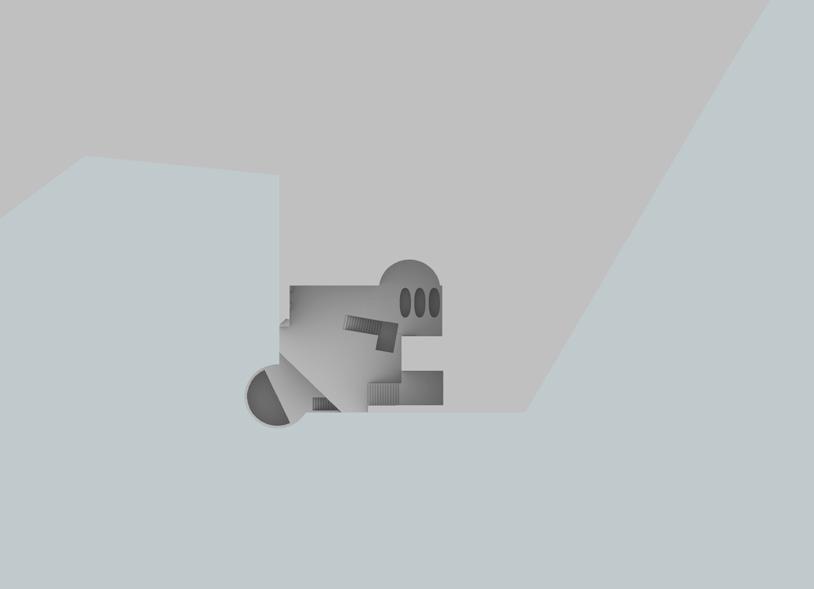
 Ground Floor View
 Typical Floor View
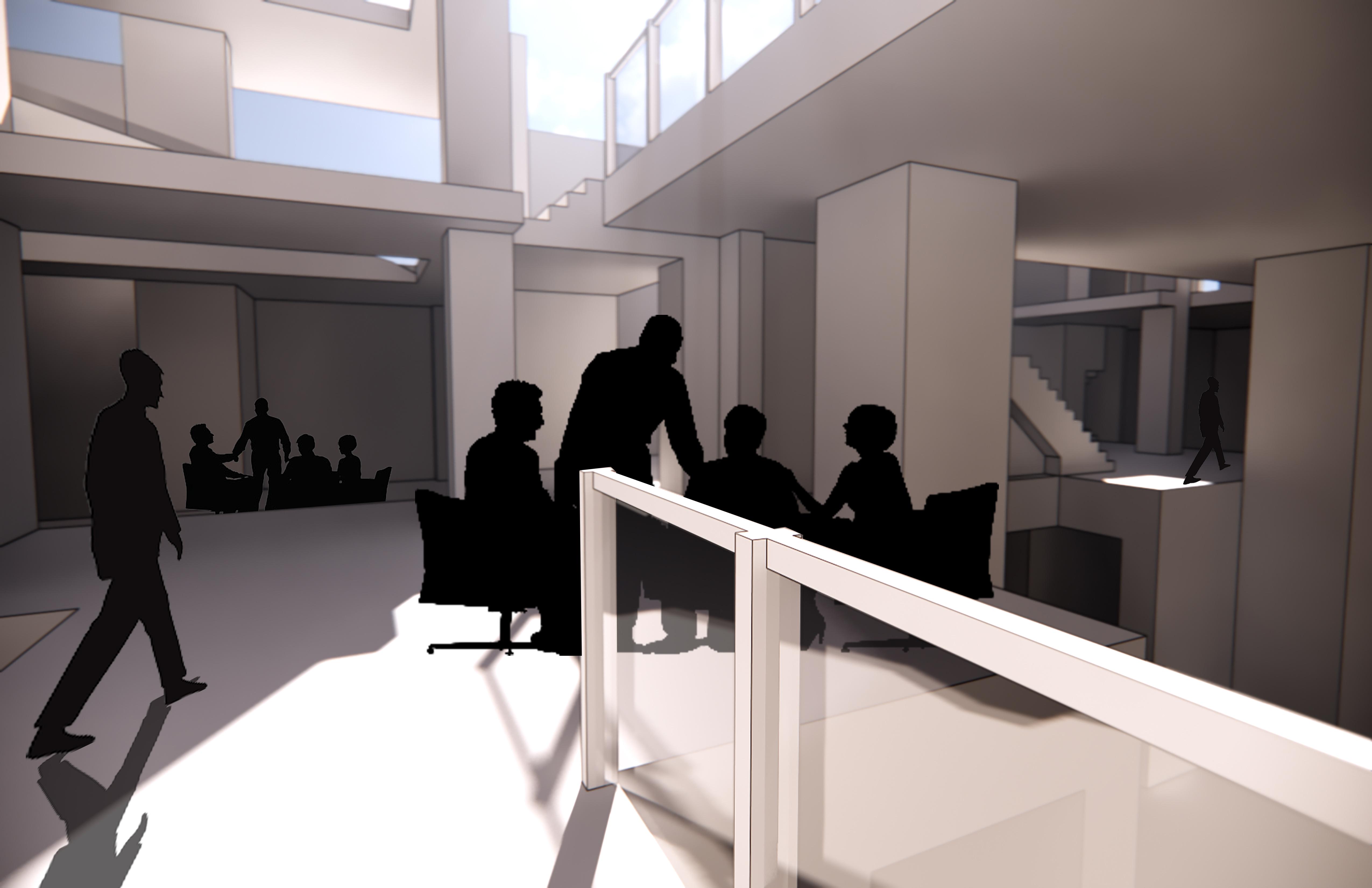
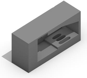
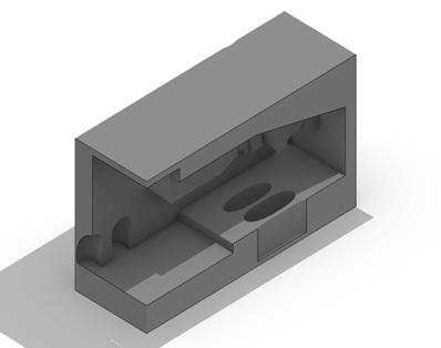
The WeDesign Un-House Year 2 - Fall 2022 (Architectural Design 1)
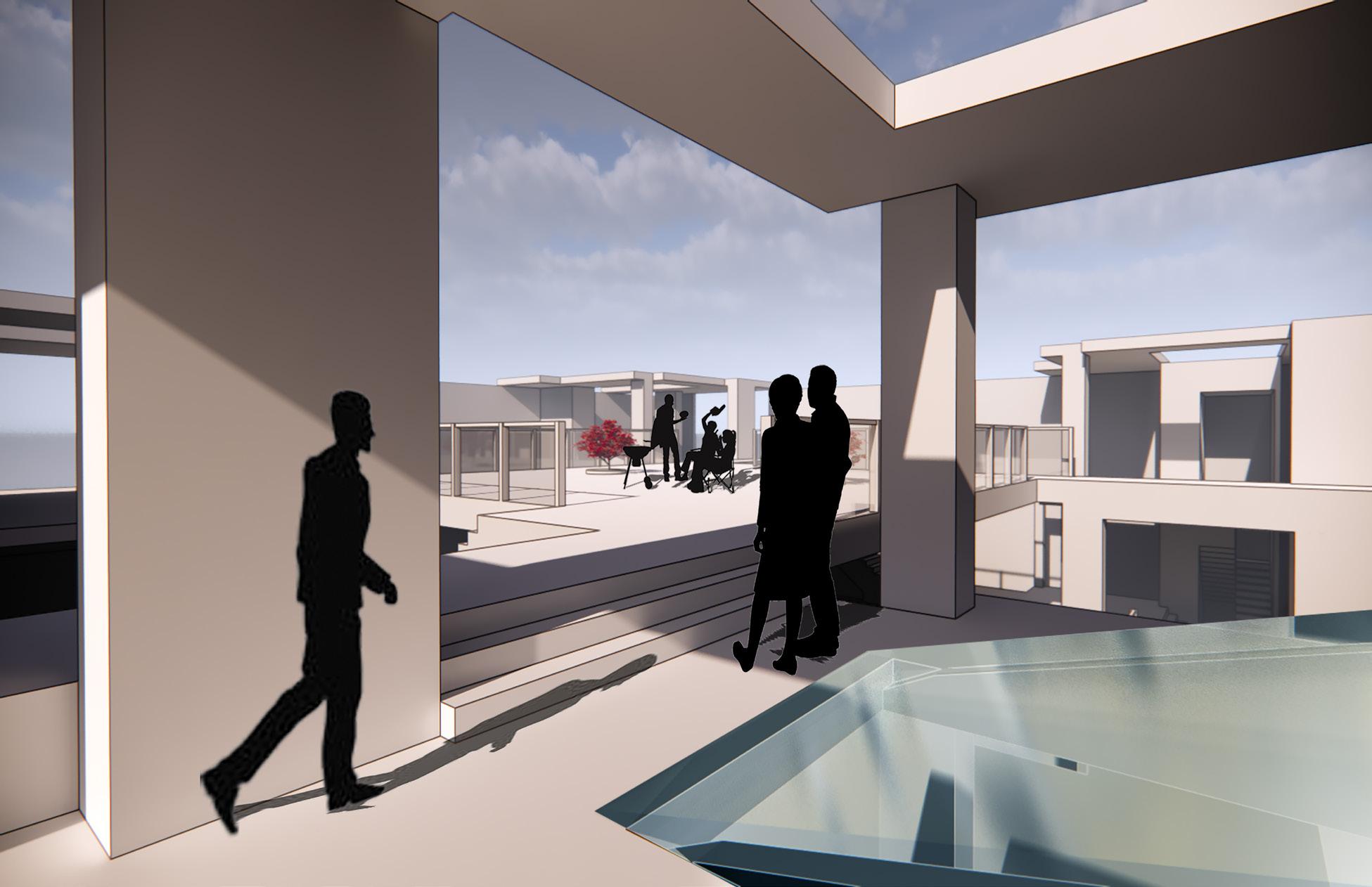
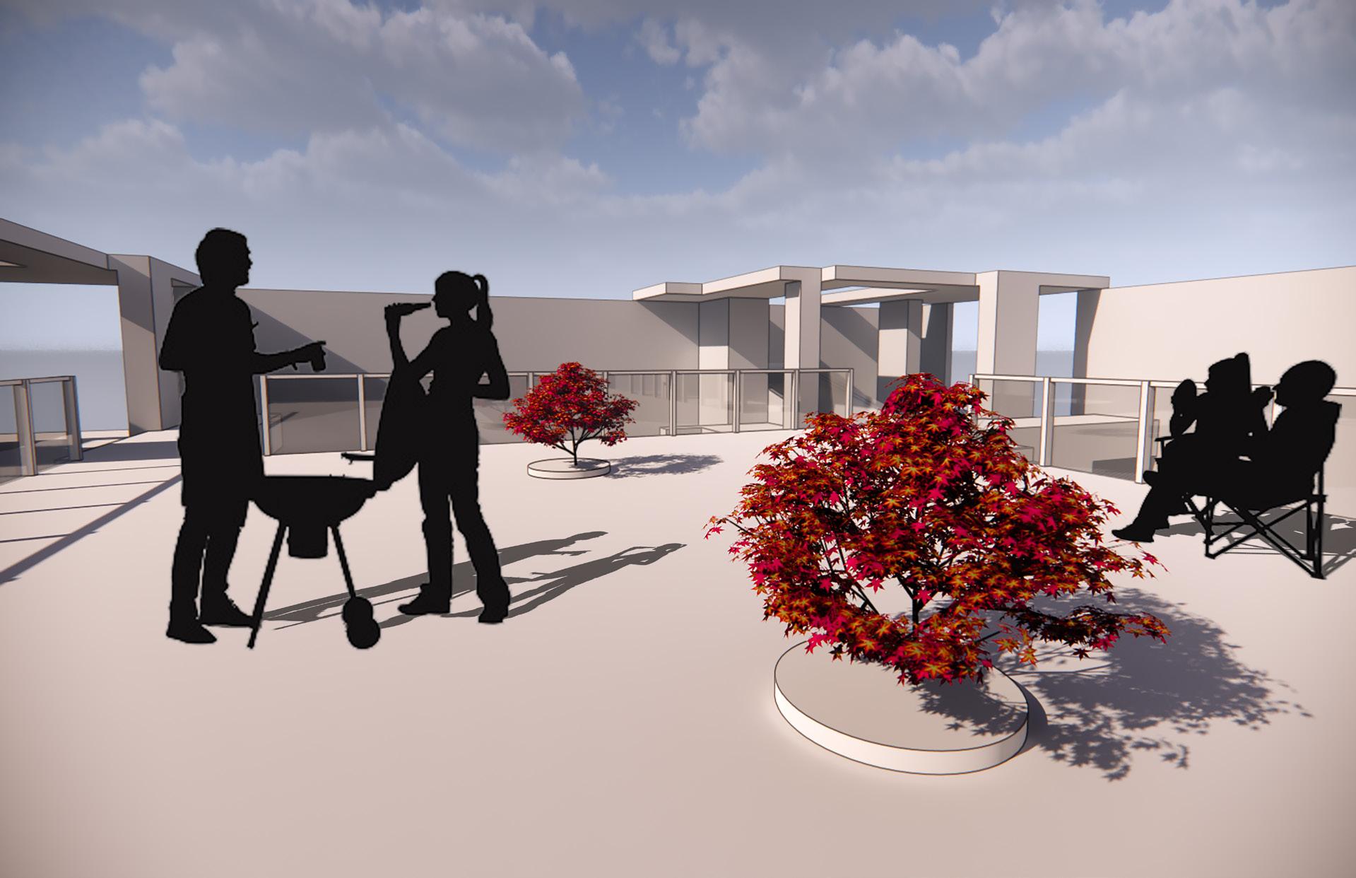
The “Un-House” is the advanced elaboration of the typical house for the typical family. It’s much bigger in size (108’ x 108’) and is much more exposed to the natural elements. It generally serves a purpose beyond being somewhere to eat and sleep, so it can’t just be called a house or even a residential building. The concept of the “house” is broken apart and expanded upon, thus giving it the title of the “UnHouse.”
The WeDesign Un-House is the house of remote workers. Based on a rented space from the company WeWork, this proposed building would be available for workers to rent as a place to not only present and share ideas, but also to casually hang out and sleep through the night.
PRECEDENT 1: Maison Des Gardes Agricoles
Architect: Claude Nicolas Ledoux
Design Date: 1784
(Proposed) Location: France
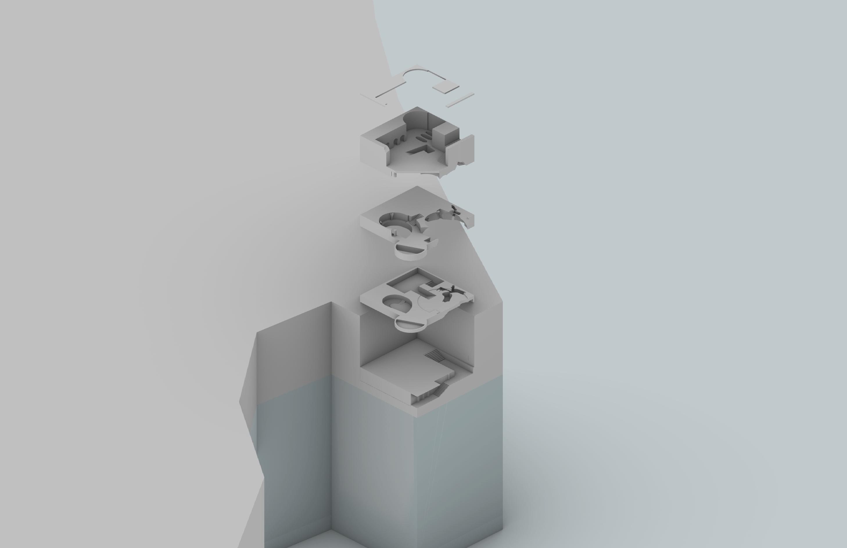
SouthWest Standard / Exploded Axonometric
PRECEDENT 1: Maison Des Gardes Agricoles
Claude Nicolas Ledoux
France
Maison Des Gardes Agricoles
Architect: Claude Nicolas Ledoux
Design Date: 1784 (Proposed) Location: France
PRECEDENT 2: The Goldenberg House
Architect: Louis Kahn
Design Date: 1959 (Proposed) Location: Pennsylvania, USA
Final Sequence: Kahn Variation
After manipulating the fully established grid using concepts from both precedents, the final matrix (or the official project concept) was converted into 3D.
Mirroring
The 3D matrix was then copied onto each corner of the 108’x108’ site and rotated 90 degrees each time. When they’re connected at the corners, not only is a central void esssentially defined, but so are the quadrants.
Corners
Central Rotation
Main Types:
Central
Corners
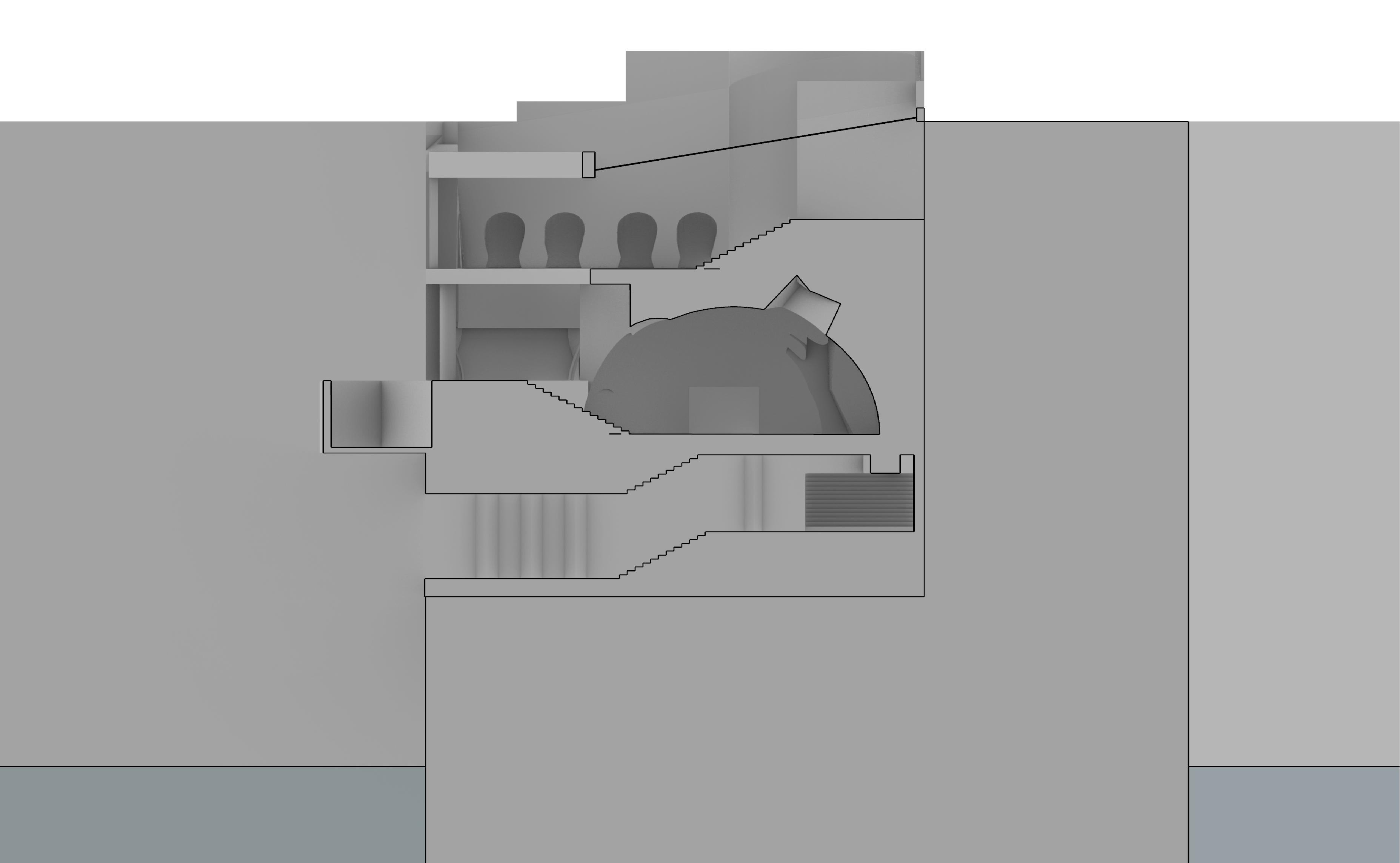
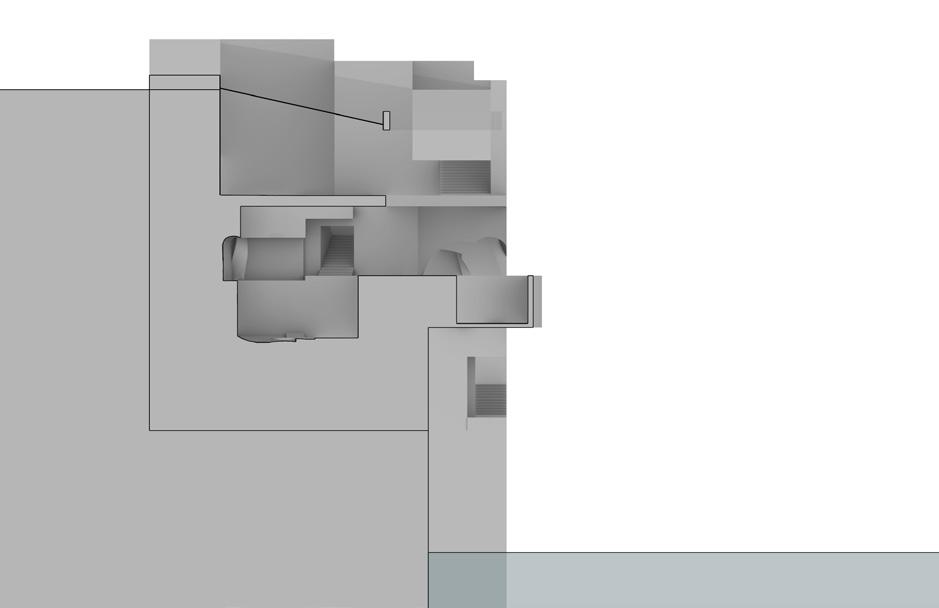
West Section
West
South
The Rewarding Waters
Year 1 - Spring 2022 (Design Fundamentals 2)
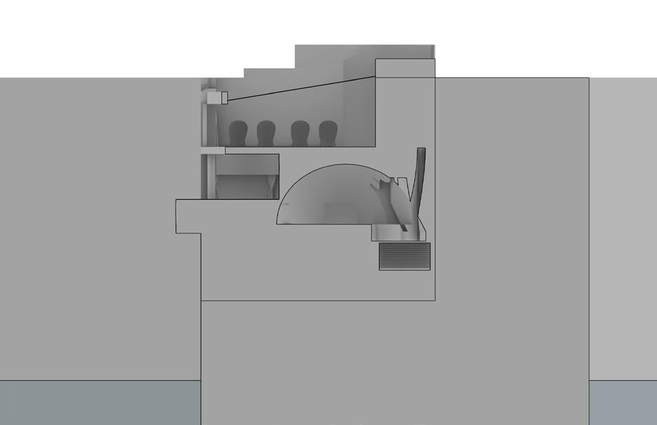
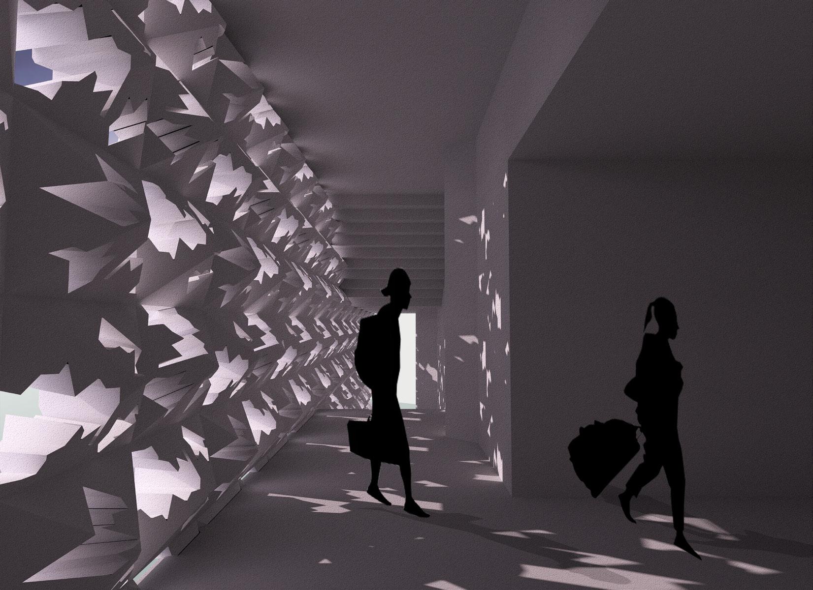
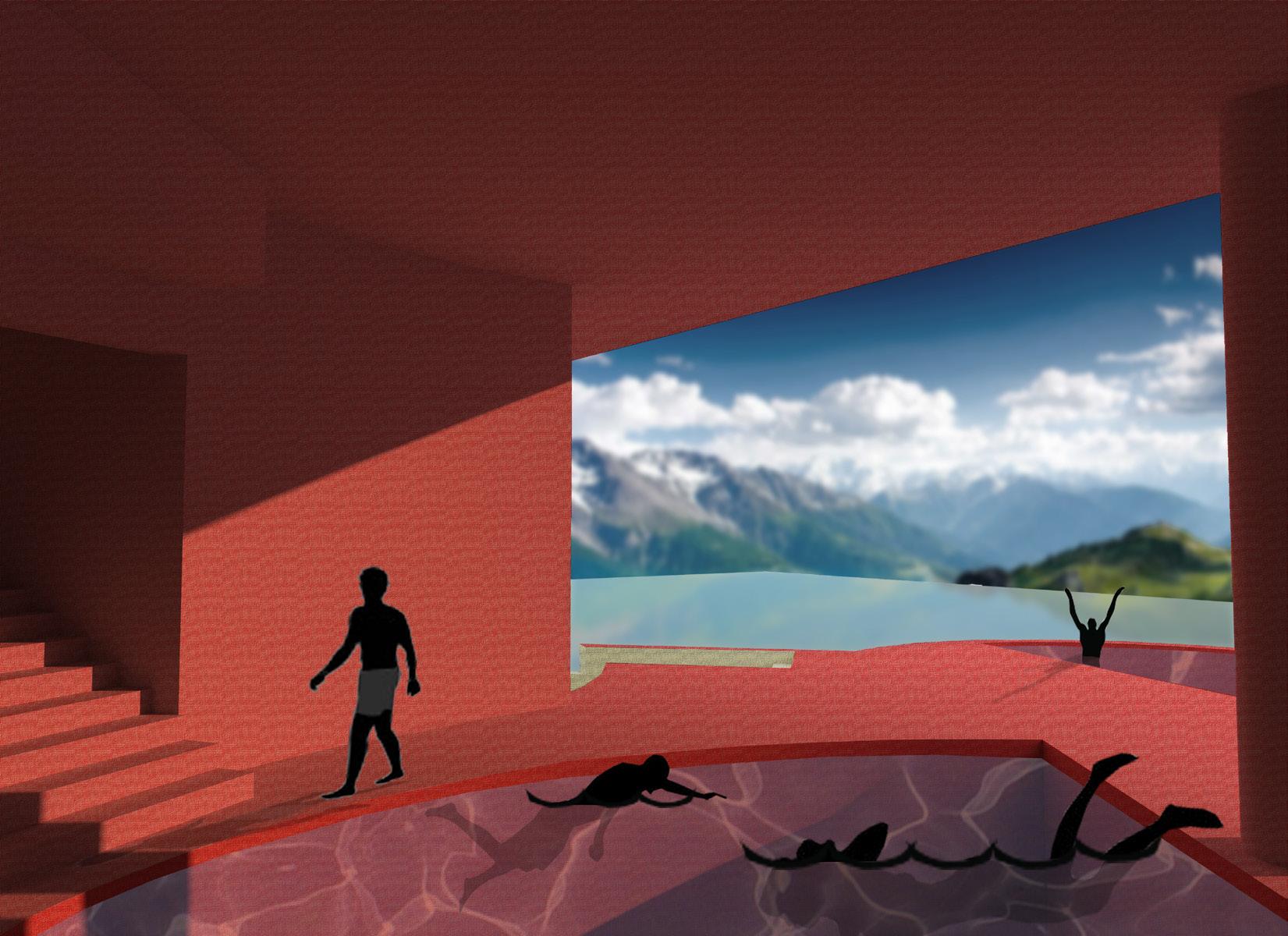
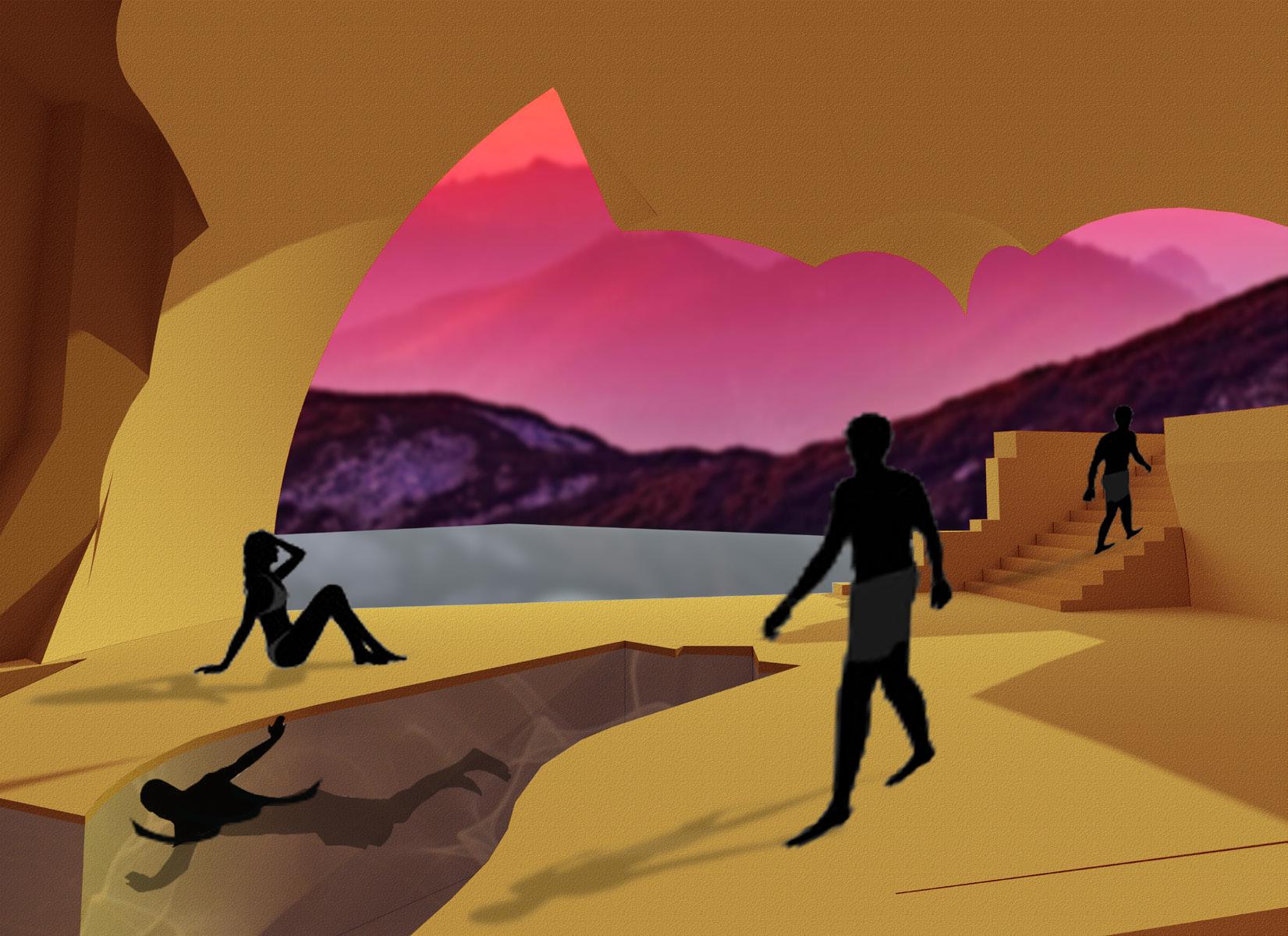
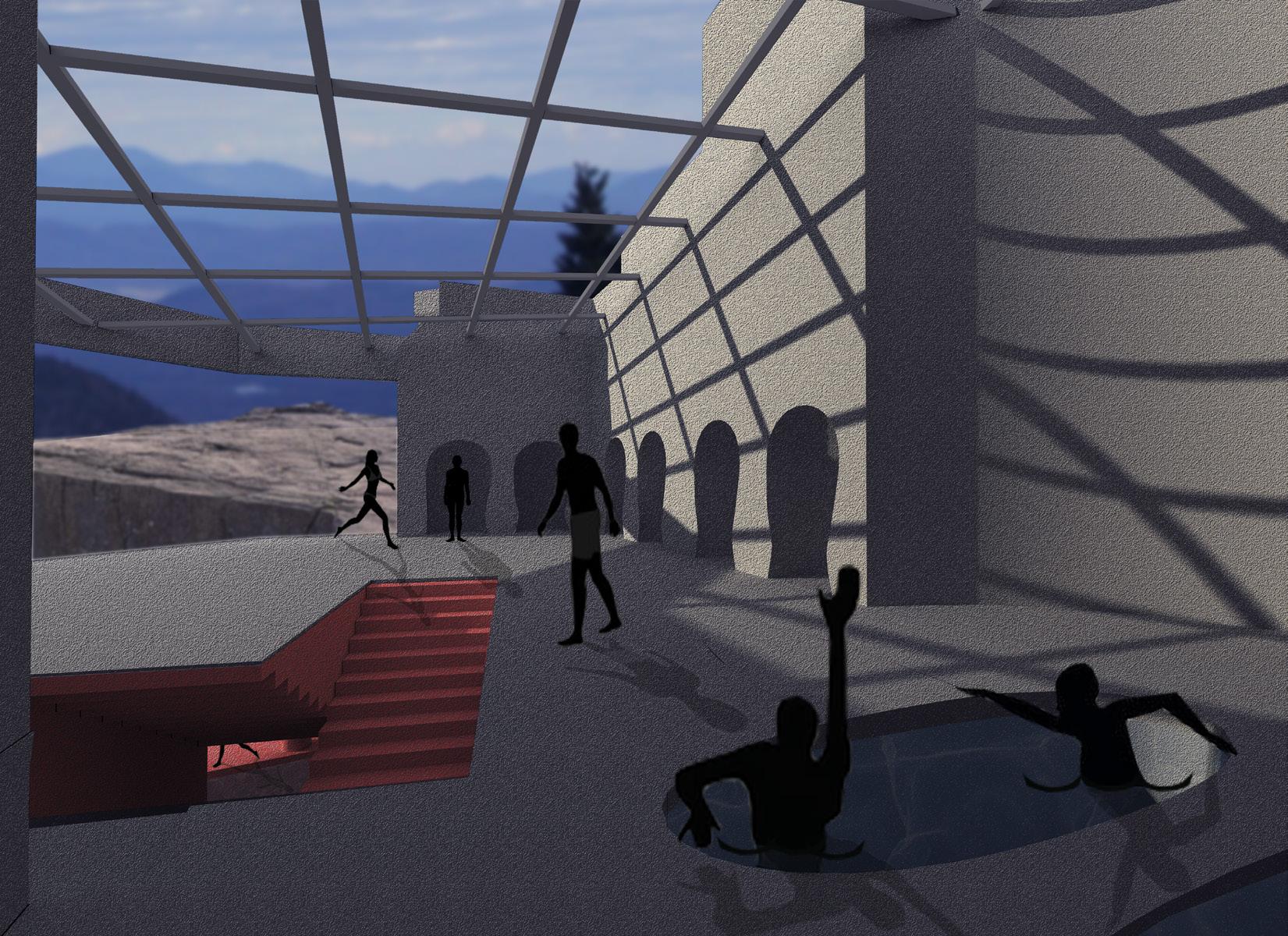
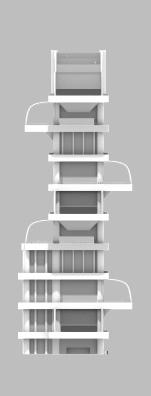
The Rewarding Waters is a bathhouse carved into the side of a cliff along the Hudson River (Palisades, NJ, USA). It’s a spa spot for travelers to unwind in various temperatures: hot, warm, and cold. These temperatures are regulated within the bathhouse based on the color of the space in which they’re contained. In other termsthe warmer the color of the space, the warmer the temperature, and vice versa.
You arrive at the entrance via ferry and ascend to each level of the bathhouse through flights of stairs. That way, as you climb up, you’re “rewarded” with a new section at each level to relax in and enjoy.


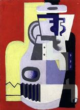
“Still Life with Accordian” by Le Corbusier (1920)
Rendered Painting (Rhino 7) DARK
According to my personal analysis, the cold colors of the painting are located in the foreground, the warm colors are in the middle ground, and the hot colors are located in the back. In that case, the colors get warmer/colder as you move closer/farther away. This concept will be extremely useful soon.
1.) Gray Eye
2.) Gray Accordian
3.) Gray Lost Handle
4.) Black Cap
5.) Black Neck
6.) Black Half Bottle
11.) Lavender Lid
7.) Red Holder
12.) Lavender Broken Body
8.) Yellow Support
13.) Completed Painting
9.) Yellow Half Bottle
14.) Original Painting
10.) Lavender Neck
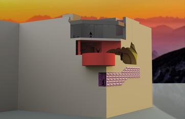
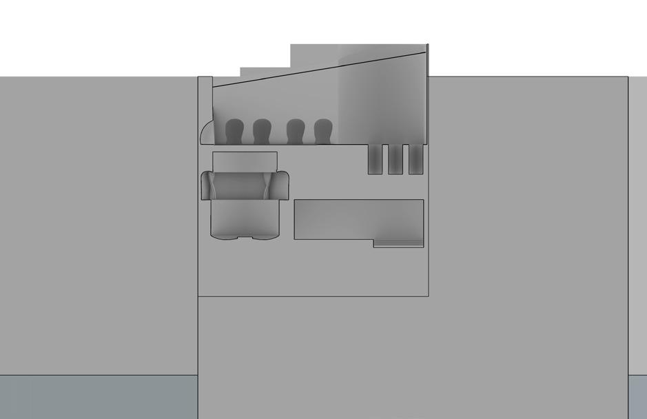
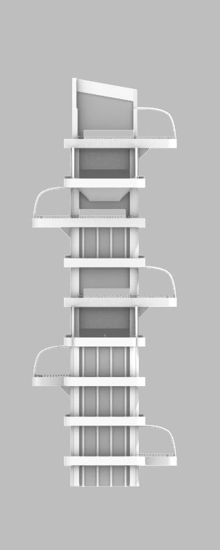
The colors of the space will get colder/darker as you progress through the entire building. AS THIS HAPPENS:
- The temperature of the spaces will drop.
- The water program of the spaces will be more accomodating to colder temperatures (Hot baths in the Hot Space, Cold Plunges in the Cold Space, etc.)
-The spaces will be on higher elevations, thus playing into the “rewarding” factor of continuously climbing stairs to get to the next level.
-Exposure to the outside increases, therefore the view outside increases. This also plays into the “rewarding” concept by essentially making you work for your view.
Early Model Iterations
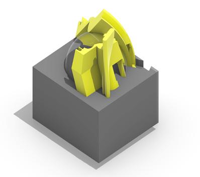
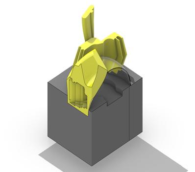

Vessel Scale (Smallest to Biggest)
Vessel
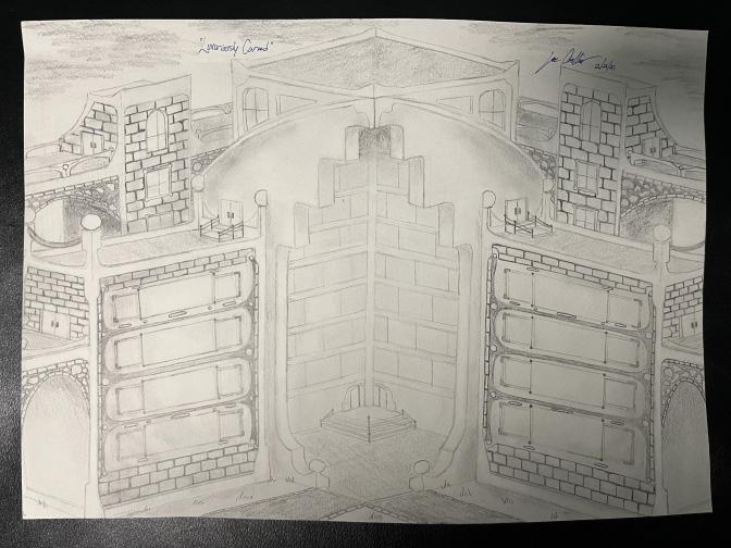
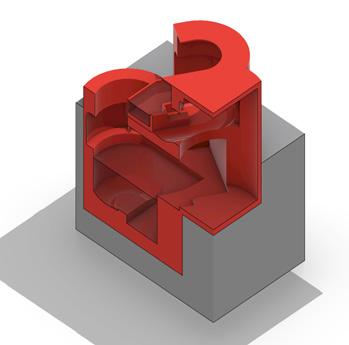
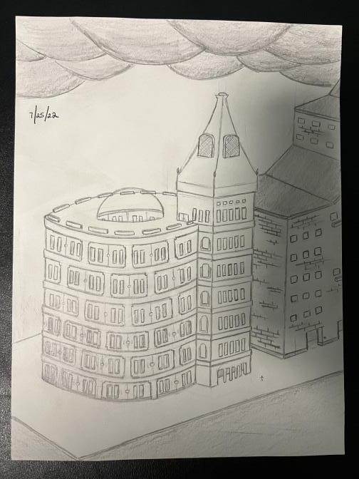
LUXURIOUSLY CARVED -- Grand Hotel Concept
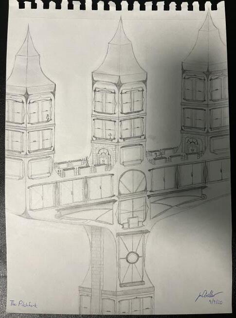
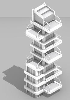
THE PITCHFORK -- Mixed Use Skyscraper Concept
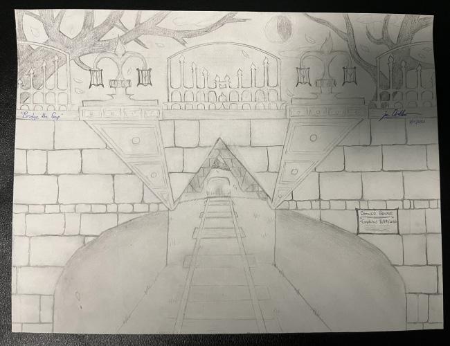
ROCKER BRIDGE -- Small Pedestrian
Bridge Overlooking Railroad Concept