14 minute read
Integrated Temperature Model (ITM) – Part I
The production of hot strip at conventional Hot Strip Mills does not attain the best overall result as the optimization of one process step may have adverse consequences for another process step.
A model designed by SMS group considers the interaction of the individual process steps in hot strip making with respect to the temperature profile. – Part I of a field report.
Advertisement
AUTHORS: A. Sprock, C. Hassel, K. Grybel, H. Hof, W. Fuchs, SMS group, Germany
CONTACT: August.Sprock@smsgroup.com
The production of hot strip at conventional Hot Strip Mills is divided in individual process steps, starting from reheating, rolling at roughing mill and finishing mill, strip cooling at run out table and coiling. All the process steps run in principle one after the other and independently. In this way, each individual processing step is optimized in isolation while adhering to the individual set values. This conventional procedure does not attain the best overall result as the optimization of one process step may have adverse consequences for another process step, i.e. the interaction between them is neglected. The Integrated Temperature Model (ITM) of SMS group completely remedies these disadvantages. By using the temperature setpoints from the traditional strategy an integrated, higher-level temperature profile from the furnace to the coiler is determined. This profile is updated cy-
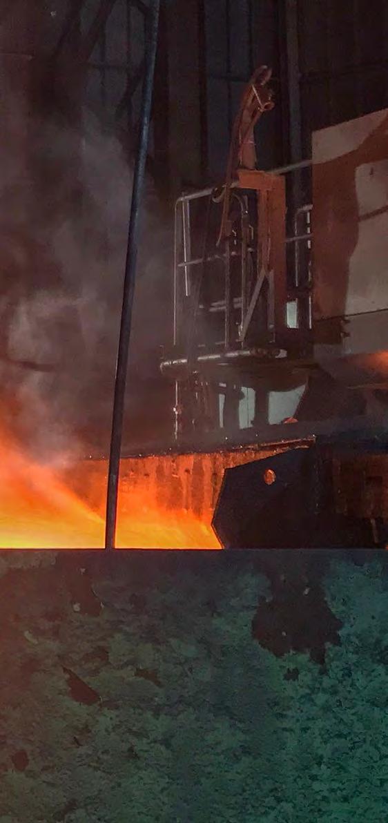
Figure 1: Schematic view of the individual process steps for the production of hot-rolled strip

clically; the individual process steps interact via this profile. Possible deviations from the temperature profile due to disturbances are corrected by controller actions of the Integrated Temperature Model (ITM) under consideration of the plant limits and the microstructure. The coupled Microstructure Property Model (MPM) calculates the components and the mechanical properties of the hot strip as a result of its thermal and mechanical treatment in the overall process. This concept extends the possibilities to improve the desired mechanical properties with the Microstructure Properties Optimizer. The advantages of additional plant components, such as a transfer bar cooling system and compact cooling, may be analyzed and optimized quantitatively by this integrated temperature model in order to realize a gain in production and product quality.
The production of hot-rolled strip takes place in individual process steps
Figure 2: Schematic view of the individual process steps and the corresponding temperature curves

which are executed one after the other. In a hot strip mill, the slabs are first pre-heated to the required processing temperature; during the process of roughing-down a specified transfer bar thickness is achieved. Subsequent rolling in the downstream finishing stands then results in the desired final geometry. The hot-rolled strip is then cooled down to a defined target temperature in the cooling section. For further processing and transport, the strip is then coiled on the coiler unit, see Figure 1. In the individual processing steps, adherence to the setpoint values is of utmost importance. Only in this way can the desired product quality be ensured. Among other factors, the size (thickness, width) and temperature must be precisely set. For this purpose, prediction models are used which – based on physical and empirical equations – determine the energy and work as well as the coolant flow rate for the individual process steps required to obtain a certain product with the desired size and temperature [1] – [5]. SMS uses the following models to describe the individual processing steps:
Figure 3: Illustration of problematic temperature control on the finishing mill and coiler pyrometers


• L2 Furnace Calculation/Control • Pass Schedule Calculation/Control
Roughing Mill (PSC RM) • Pass Schedule Calculation/Control
Finishing Mill (PSC FM) • Cooling Section Calculation/Control (CSC). As a rule, the processing steps are set up in such a manner that there are as few differences as possible between the desired target values and the measured actual values. Since the processing steps are executed one after the other and their process control is not independent of one another, separate optimization of the individual process steps may be dis- Figure 4: Illustration of a higher-level temperature curve from the furnace up to the coiler advantageous when the goal is to achieve an optimal overall result with the best would rather avoid abrupt speed chang- • High production figures: Temperaproduct quality. If, for example, the de- es due to possible temperature devia- ture and speed are at their upper sired final rolling temperature is not tions on the coiler pyrometer. Particu- limit reached, the strip speed increases during larly critical areas are the strip head end • High process stability: Temperature rolling and the deviation between the and strip tail end, where there are often and speed are in the safe, medium measured actual temperature and the significant changes in the strip speed. range target temperature is reduced. The fin- • Optimal product properties: Temishing mill temperature control system Determination of a higher-level perature and speed are optimized will continue to increase the speed until temperature profile using the ITM for each material rolled the temperature difference has been The strategy developed and enhanced by • High energy savings: Temperature eliminated, see Figure 2. The speed in- SMS eliminates the boundaries between and speed are at their lower limit. crease results in a measured coiler tem- the processing steps and sends the indiperature that exceeds the target temper- vidual setpoints for speed and tempera- The higher-level temperature curve is ature. In this case, the temperature ture to an integrated temperature mod- superordinate to the individual process control system will add more water in el (ITM) to create a higher-level temper- parts and thus eliminates the restricthe cooling model or reduce the speed ature profile. This temperature profile tions between the individual process in order to reduce the deviation. This takes into account the individual pro- steps from the conventional approach. leads to a dilemma since optimization of cessing steps during preheating, rolling Figure 4 shows an example for a highone processing step leads to an unfavora- in the roughing stand and in the finish- er-level temperature curve. The setble overall result. This is shown in detail ing stands and cooling-down in the cool- points are integrated in a higher-level in Figure 3. As soon as a deviation occurs ing section. The temperature curve is temperature curve. Using the primary on the finishing mill pyrometer, the con- mainly influenced by the plant limits, data of the current strip, the complete troller changes the strip speed to com- process stability and changes in the ma- temperature curve and the overall speed pensate for this deviation. If water is not terial microstructure during processing. profile are calculated and optimized for added or switched off in time in the This means that the temperature curve the entire strip length. In this way, strip cooling section, the coiler temperature can be modified under these boundary speed and temperature values are explicwill deviate from the desired target val- conditions to follow the operating itly defined before the strip enters the ue. The controller in the cooling model modes specified by the plant owners: finishing mill or the cooling section. The temperature curve is determined using the Fourier heat equation. When solving the Fourier heat equation, the exact description of the energy balance and possible transformations is a central task. The temperature model uses a semi-empiric approach that takes into account the determination of the transformation temperature values with regression equations, a diffusion-controlled kinetics approach and the energy balance of the individual phases via thermodynamic potentials and the para-equilibrium condition (PE). In this way, the temperature distribution is determined via the energy balance from the furnace up to the coiler. The calculation is updated cyclically with the comFigure 5: Illustration of optimized temperature control on the finishing mill and coiler pyrometers plete material model.
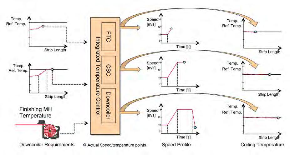
Figure 6: Temperature curves on the finishing mill and coiler pyrometers

Predictive process control
In the case of deviations from the target temperature curve, the ITM tries to adjust the strip speed in such a way that a minimal deviation is reached at the downstream measuring points. This means that if the hot strip enters F1 with a temperature deviation, the preset strip speed for the rest of the strip will be changed by the ITM in such a manner that the target finishing mill temperature can be adhered to. At the same time, the updated strip speed prediction is also available in the cooling model. In this way, the water flow rates are adjusted accordingly over the entire strip length, so that the target coiler temperature is also adhered to.
If there is a temperature deviation at the finishing mill pyrometer, the strip speed prediction is adjusted in order to obtain the target value, see Figure 5. This modified speed prediction is also immediately available in the cooling model, so that based on this scheduled speed profile water can be added or reduced so as to adhere to the target coiler temperature. As a consequence, there are no unexpected speed changes resulting in any undesired jumps in the measured coiler temperature. The processes now operate with a reciprocal effect and are harmonized with each other.
Possible deviations are corrected in a model-based manner. This is important since a change in speed or water flow rate does not result in a proportional change in temperature. If the deviation and the target temperature are within the transformation range, the correction is performed in a different way than for a deviation outside of the transformation range. The phase transformation is considered in the energy balance; in this way the controller can precisely adjust the required amount of make-up water.
Figure 6 shows an actual example. In the upper section of the figure, the finishing mill and coiler temperature values are shown as a function of the strip length. For a better overview, the temperatures are displayed as differences from the measured temperature minus the reference temperature. In the lower part of the figure, the curve of the strip speed and in the middle part of the figure, the activated water flow rate is indicated. Since the measured finishing mill temperature is just below the reference temperature after 100 m of strip length, the strip speed increases. The modified strip speed prediction is also immediately available in the cooling model, and the water flow rate will be

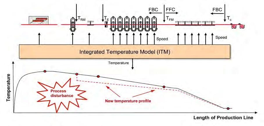
adjusted correspondingly to the speed change. As a consequence, abrupt changes in the measured coiler temperature are prevented; the measured coiler temperature is at its target value. If the production process is disturbed and the measured temperature significantly deviates from the target temperature curve as the result of a delay, the desired target temperature cannot be adjusted anymore without adapting the downstream processes, taking into account the plant limits, the process stability or microstructural changes of the material, see Figure 7. In this case, the target value is not reached in one of the process steps. The ITM defines a new temperature profile and at the end sets the desired temperature, see Figure 7. The higher-level temperature profile can now References London, UK, 1996, P. 36-58 Advertorial
The solution: alcohol-resistant markers
In industry, permanent labelling on metal, glass or plastic is part of many dayto-day routines. It’s therefore advisable to use alcohol-resistant ink. One reliable
Figure 7: Illustration of a corrected temperature curve following a process disturbance
be used to make statements about the microstructure, since the temperature distribution and the forming in the processing steps form the basis for the quantitative prediction of the composolution is the edding 750 paint marker. Proven to be resistant to alcohol, its paint-like, opaque ink shows up very well on dark and transparent materials. What’s more, the ink is even heat-resistant.
What makes edding paint markers resistant to alcohol?
Solvents ensure that the marker ink remains fluid to enable flawless writing. When writing on a given material, the solvent evaporates. Once dry, a marking can be removed with the same solvent as the one found in the marker ink, or nents and the resulting mechanical properties.
The second part of this article will be pub-
[1] Jin, D.; Hernandez-Avila, V.; Samarasekera, I.; Brimacombe, J.: An integrated process model for the hot rolling of plain carbon steel; Proceedings of the 2nd International Conference on Modelling of Metal Rolling Processes, [2] Zhou, S.: An integrated model for hot rolling of steel strips; Journal of Material Processing Technology, 2003, Vol. 134, No. 3, P. 338-351 [3] Colas, R.: Modelling heat transfer during hot rolling of steel strip; Modelling and Simulation in Materials Science and Engineering, 1995, Vol. 3, P. 437-453 [4] Devadas, C.; Samarasekera, I.: Heat transfer during the hot rolling of steel strip; Ironmaking and Steelmaking, 1986, Vol. 13, P. 311-321 [5] Yanagi, K.: Prediction of strip temperature for hot strip mills; Transactions of the Iron and Steel Institute of Japan, 1976, Vol. 16, No. 1, P. 11-19
The problem: markings can be dissolved by disinfectants and sanitisers
What could be more frustrating than seeing a carefully applied marking on a workpiece become smudged or rendered illegible simply by touching it? Yet in this time of the coronavirus pandemic, this is happening more frequently. The reason for this is the increased use of hand sanitisers which can easily come into contact with the material on which the marking is written. Hand sanitisers usually contain alcohols which have the ability to dissolve many types of ink.

lished in MPT International No. 1 / 2021 a similar one. That’s why the solvent in an alcohol-resistant marker such as the edding 750 paint marker isn’t based on alcohol.
Preventative measure: everyone should label their own tools
The IGM (German metal workers’ union) recommends that workers should, where possible, only use their own equipment such as tools and markers, and should disinfect them regularly. In this scenario, too, it’s advisable to use an alcohol-resistant edding paint marker for labelling purposes.
We are

KOHLHAGE Group – Automotive Solutions made in Germany
The KOHLHAGE Group employs more than 200 employees with an annual turnover of over 45 million. With that KOHLHAGE is large enough to play on the international stage of the automotive industry while staying fl exible enough to be able to react to changing market conditions at short notice. Whether you are in the market for a smart fastening solution, a precise tubing component or large structural assembly we can provide you with proven technical expertise, rigorous standards of quality and an all around customer focused mentality that will satisfy all your automotive needs.
KOHLHAGE Automotive
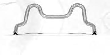
Bent tubes and complex assemblies KOHLHAGE’s wide range of tubing ’s wide range of tubing Exhaust fl ap components has been an integral part of Germany’s automotive sector part of Germany’s automotive sector for many years. KOHLHAGE offers numerous safety-relevant and crash-tested structural components, crash-tested structural components, precise fl uid-carrying tubing solutions and precise fl uid-carrying tubing solutions and high quality exhaust fl aps for motorcycles, passenger cars or commercial vehicles. cars or commercial vehicles.
KOHLHAGE E-Tech
Solutions for E-Mobility
The manufacturing of electrical vehicles brings about new challenges in both the structural design and the passenger safety within powertrain solutions. Based on many years of experience in the industrial production of complex component assemblies we develop and produce a range of support frames and large structural components for the mounting of electric motors and their necessary attachments. All to the individual specifi cations of our customers. Power unit carrier for electric mobility
Height adjustment for steering wheels
Oil tubes
Cooling tubes
KOHLHAGE Automotive Tubes Kunshan Tubes Kunshan
For the Asian market
In 2016 KOHLHAGE founded a production facility close to the chinese economic and commercial centre of Shanghai. From there KOHLHAGE can directly supply their Chinese, Asian and international customers with our proven expertise in tubing solutions.
Media carrying tubes Structural components

KOHLHAGE Fasteners
Challenging solutions for fastening technology
Whenever you are in the market for a demanding and complex fastening solution our engineers will advise and support you from conception of a product to full industrial mass production. Our engineers provide you with specialist expertise about all manufacturing processes and will work with you to fi nd the most suitable technical and economically feasible production method for your desired fastening solution.
Fasteners


