8 minute read
ENGINEER’S NOTEBOOK
aids for the structural engineer’s toolbox STRUCTURE’s February 2017 Engineer’s Notebook discussed the design requirements and methods to laterally brace (bridge) axially loaded cold-formed steel stud walls. This article provides the design requirements and methods to anchor, or complete the load path, for the lateral bracing (bridging) of axially loaded cold-formed steel stud walls.
Design Requirements
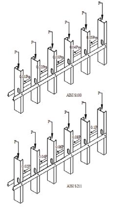
The design requirements for the bridging components of axially loaded cold-formed steel studs are described in AISI S100-12 North American Specification for the Design of Cold-Formed Steel Structural Members, Section D3.3, and Section B3.1 of AISI S211-12 North American Standard for Cold-Formed Steel Framing – Wall Stud Design. The bridging forces are assumed to accumulate linearly with respect to the number of studs, and the load path must be completed for the bridging forces. The forces accumulate and must be removed Mechanical Bridging Anchorage of Axially periodically as the force in the bridging row reaches the design capacity of the bridgLoaded Cold-Formed ing member. The mechanism for resisting Steel Studs the cumulative bridging force is known as the “anchorage” of the bridging. Figure 1 illustrates the accumulation of
By Nabil A. Rahman, Ph.D., P.E.
Nabil A. Rahman is the Director of Engineering and R&D for The Steel Network, Inc. and a Principal at FDR Engineers in Durham, NC. He is the current chairman of ASCE-SEI Committee on Cold-Formed Steel Members. He serves as a member of the Committee on Specification and Committee on Framing of the American Iron and Steel Institute (AISI), and a member of ASCE Committee on Disproportionate Collapse. He can be reached at nabil@steelnetwork.com.
Figure 2. Anchorage of bridging using flat-strap cross bracing.

the bridging force according to the design requirements of AISI S100 and AISI S211. When using the AISI S211 approach, there is no explicit brace stiffness requirement compared to the approach in AISI S100. As a result, AISI S211 uses a more conservative strength requirement, 2% compared to 1% used in AISI S100. If AISI S100 is used, brace stiffness must be evaluated for each stud in accordance with Section D3.3, and the accumulation must also be considered. Although AISI S100 does not provide a method to accumulate the stiffness requirements for multiple studs, the Architectural Engineering Journal research paper Bracing Demand in Axially Loaded Cold-Formed Steel Stud Walls (Sputo and Beery, 2008) suggests the following equation for this stiffness accumulation: βrb,n = βrb [0.4n2 + 0.5n] where, βrb,n = Required brace stiffness for multiple studs with (n) number of equally spaced intermediate brace locations βrb = Minimum required brace stiffness to brace a single compression member n = Number of equally spaced intermediate brace locations
Anchorage Methods
The method of bridging anchorage may vary depending upon the magnitude of bridging force accumulated in the bridging row, as well as the preference of the design engineer. One of the common methods of bridging anchorage consists of flat-strap cross bracing attached from the bridging line to the bottom of the wall on each side of the stud (Figure 2). The system functions in tension only to transfer cumulative bridging forces to the bottom track and the floor slab; thus a cross bracing pattern is required to anchor stud bridging for buckling
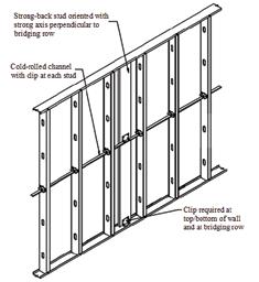
in either direction of the wall. For this type of system, the designer should specify the strap size; thickness and width, as well as the connection requirements at both the bridging line and the bottom track of the wall. Stiff ness resistance is obtained through a combination of the stiff ness of the fl atstraps, the stiff ness of the bottom track, and the connections between them. When the bridging member is a cold-rolled channel inserted through the punch-outs of the studs, the concept of anchoring the bridging to the bottom of the wall can also be achieved with a diagonal piece of a stud or track welded to the bridging line and the bottom track, as shown in Figure 3. Welding is typically preferred when wall panels are assembled in a panel shop versus being assembled on site. An alternative bridging anchorage method consists of a “strong-back” stud oriented so that the strong axis is perpendicular to the bridging row, and attached to both the bridging line and the top and bottom of the wall. Th e stud acts in bending about its strong axis and transfers the bridging force into the fl oor slab through a series of clips, as shown in Figure 4. Th e designer must specify the stud type and connections
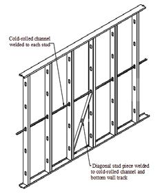
Figure 3. Anchorage of bridging using welded diagonal brace. Figure 4. Anchorage of bridging using a strong-back stud.
to be used based on the cumulative force in the bridging line. Stiff ness resistance is obtained by a combination of the stiff ness of the bridging member, the stiff ness of the strong-back stud, and the stiff ness of the connection between them. Th is type of anchorage system may also be used with a fl at-strap bridging method by using two strong-back studs attaching the web of the strong-back to the fl at-strap on each side of the wall, as well as to the top and bottom track. Th e two strong-back studs do not need to be at the same location but may be alternated for ease of installation. Another method of bridging anchorage is using a built-up stud column placed at
ADVERTISEMENT–For Advertiser Information, visit www.STRUCTUREmag.org
DESIGNED not to be seen

Multi Strand Anchor
Systems
For Suface Stabilization


Williams Type B System Extruded Free Stress Length Typical Strand Anchor – PTI Class II
Williams Systems Include: Corrosion Protection:

• The most technologically advanced extrusion equipment for the manufacture of permanent and temporary anchors. • Strand Anchors are typically produced from 0.6" diameter, 7 wire strand [f pu = 270 ksi, 1862 N/mm2] meeting ASTM A416. • Anchors arrive to the jobsite fully fabricated and packaged in coils to allow for installation in areas where there are clearance issues or bench width constraints. • Williams C4.6 and C7.6 Wedge Plates (anchor heads) have been prequalified by Caltrans, with approval #40114a and #40114b respectively, for prestressed ground anchor construction. Applications: • The anchor system is manufactured in accordance with the Post-
Tensioning Institute’s Recommendations for Prestressed Rock and
Soil Anchors. • Williams Strand Anchors are supplied with either PTI Class I or
PTI Class II classification.


• Foundations • Landslide Mitigation • Permanent Tieback Systems • Dam Tie-Downs • Temporary Excavation Support • Slope Surface Stabilization
Williams Form Engineering Corp. has been a leader in manufacturing quality products for the customer service, for over 80 years.
Belmont, MI 616.866.0815
San Diego, CA 858.320.0330 Golden, CO 303.216.9300 Lithia Springs, GA 770.949.8300 Kent, WA 253.854.2268 Portland, OR 503.285.4548 London, ON 515.659.9444 Collegeville, PA 610.489.0624 For More Information Visit:
williamsform.com
specifi c intervals along the wall length, such as wall openings, as shown in Figure 5. Th e built-up stud section should be capable of resisting the applied axial load as an unbraced section, as well as resist the cumulative bridging forces within the plane of the wall. Th us, a combined loading condition exists, the applied axial load and the bending loads induced from the bridging row as well as any out-of-plane pressure acting on the built-up column. Th e use of a weldment or HSS member is an option for the built-up member if larger capacity and stiff ness are desired. Bridging anchorage is critical to completing the load path, and ensuring that the tendency of the studs to buckle in fl exural and torsional buckling modes is restrained by the bridging. Th e type of bridging method used will determine the anchorage spacing and the possible anchorage methods. It should be pointed out that the bridging methods that are capable of resisting load in both tension and compression may require a single anchorage point along the wall length. However, tension-only bridging systems always require a minimum of two anchorage locations along the wall
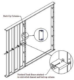
Figure 5. Anchorage of bridging using a built-up section.
length to resist the buckling of the wall in either direction. For a numerical design example illustrating the design of a bridging member and its anchorage, refer to Cold-Formed Steel Engineers Institute TN W400-16, www.cfsei.org. Th e design example provides the detailed calculations for lateral bracing (bridging) and bridging anchorage of axially loaded studs, and compares the AISI S100 and AISI S211 bracing design alternatives available to design engineers. It is shown that in most cases, despite the need to design for larger force when using AISI S211, the more conservative strength requirement in AISI S211 proves advantageous over using AISI S100 for the following reasons: • Strength calculations for both methods are similar and fairly straight forward, while stiff ness calculations can be quite lengthy. • Stiff ness calculations require estimation of the stiff ness of the connection between the stud and the bridging, and the connection between the bridging and the anchorage member. Estimation of these values requires advanced analysis and testing, and the data may not be readily available for designers. • The accumulation of stiffness for more than a few studs is difficult to achieve with available standard bridging details.▪





ADVERTISEMENT–For Advertiser Information, visit www.STRUCTUREmag.org
RECORDS
Alexander Zuendt, P.E. Zuendt Engineering Record holder since 2011

National Council of Examiners for Engineering and Surveying®
P.O. Box 1686, Clemson, S.C. 29633 864.654.6824 Build your NCEES Record today. ncees.org/records


