49 minute read
CONSTRUCTION ISSUES


discussion of construction issues and techniques
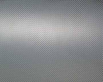
Membrane roof systems installed on steel roof decks traditionally result in a uniform transfer of wind (uplift) loads from the roof membrane to the steel roof deck and underlying supporting structure (e.g., steel joists). For example, in a built-up membrane roof system – which has been used commonly in the U.S. roo ng industry for more than 125 years – the built-up membrane is continuously adhered to rigid board insulation. e rigid board insulation, which is used to span the steel deck’s utes, is mechanically attached to the steel roof deck in a closely-spaced pattern (e.g., 1 fastener per every 3 square feet), resulting in a near uniform uplift load path. Polymer-modi ed bitumen roof systems and adhered single-ply membrane roof systems are installed in similar con gurations and result in a similar uniform uplift load path. In the 1960s, single-ply membrane roof systems were rst introduced into the U.S. roo ng market. By the late 1970s, the seam-fastened, mechani-Are Your Roof Members Overstressed? cally attached method of installation was rst introduced. With this installation method, the single-ply membrane sheet is mechanically By James M. Fisher, Ph.D., attached along its outer edges into the roof P.E., Dist. M.ASCE and deck, which results in a larger tributary uplift omas Sputo, Ph.D., P.E., load per fastener and placement of fasteners in S.E., F.ASCE linear, non-uniform loading con gurations of the roof deck and underlying supporting structure. When rst introduced, membrane sheet widths in seam-fastened single-ply membrane roof systems typically were ve feet wide, resulting in rows of mechanical fasteners spaced at ve feet on-center. Since the early 2000s, single-ply membrane sheet widths have become wider, with 10-foot-wide James M. Fisher is Vice President sheets now commonplace – resulting in rows of Emeritus, Computerized Structural mechanical fasteners spaced at 10 feet on-center. Design, Milwaukee, WI, and Currently, single-ply membrane roof systems Consulting Engineer to the Steel have clearly overtaken conventional built-up and Joist Institute. He may be reached polymer-modi ed bitumen membrane systems in at j sher. orida@gmail.com. market share. e seam-fastened, mechanically omas Sputo is President of Sputo and Lammert Engineering, LLC, Gainesville, FL, and Technical Director of the Steel Deck Institute. He may be reached at tsputo50@gmail.com. attached method of installation also has overtaken traditionally adhered methods of application. e National Roo ng Contractors Association (NRCA) annual market survey shows seam-fastened, mechanically attached single-ply membrane roof systems make up the majority of all membrane roof systems currently installed. With the present emphasis on wind resistance in design, a closer look at how seam-fastened mechanically attached single-ply membrane roof systems interact with steel roof deck and joist construction is in order. A common method of single-ply membrane sheet layout is shown in Figure 1. A common placement of mechanical fasteners is shown in Figure 2. ese concentrated line loads can
Deck
N
Fastener Lines
Figure 1. Typical membrane layout by roofers.
Figure 2. Typical fastener layout at corner zones.
Figure 3. Line attached membrane under uplift. Courtesy of the Steel Deck Institute.
severely overstress the steel deck and may also cause the steel joist below the deck to be overstressed under uplift loading. e behavior of such fastening systems, when the roof system is subjected to uplift loadings, is shown in Figure 3. e current trend in securement is for the membrane installer to mechanically fasten the membrane to the deck only along the edge of the sheet rolls to speed up the roof installation, thereby lowering installation costs. Unfortunately, the Structural Engineer of Record, and the steel deck and joist suppliers, are usually unaware of the concentrated load pattern of the roof membrane attachment. In fact, the architect of record may not be aware of the rami cations of such attachments. e Architectural roo ng speci cations may simply state that the roof membrane shall be installed per manufacturers recommendations. e roo ng installers foreman is the one who generally decides on the exact layout of the membrane sheets on the roof. at decision is made based on what layout can be installed in the fastest and least expensive
manner. Roofing suppliers and FM Global recommend the fastener line loads not be installed parallel to the deck ribs, but rather perpendicular to the deck flutes. Placing the lines of attachment parallel to the deck ribs will only load a one-foot width of the steel deck. This recommendation helps but may not eliminate potential severe overstress of the deck. Currently, the Steel Deck Institute’s (SDI) position paper, Attachment of Roofing Membranes to Steel Deck (sdi.org), states: “SDI does not recommend the use of roofing membranes attached to the steel deck using line patterns with large spacing unless a structural engineer has reviewed the adequacy of the steel deck and the structural supports to resist the wind uplift loads transmitted along the lines of attachment. Those lines of attachment shall only be perpendicular to the flutes of the deck.”
Deck Strength Example
To illustrate the potential effect of the attachment pattern, determine the deck strength for the following conditions illustrated by Figures 1 and 2. Use Load and Resistance Factor Design (LRFD) Load Combinations and American Society of Civil Engineers’ ASCE 7-1. Thus, the controlling ASCE Load Combination is 0.9D + 1.0W. (Wind calculations are not shown for brevity.) Given: A roof system located in Kansas City, MO. Category II Building. Exposure C per ASCE 26.7.3. The building is an Enclosed Building with a flat roof (¼-inch per foot). The building is 100 feet by 100 feet in plan and has an eave height equal to 30 feet. The metal deck is 1.5-inch 22-gage, wide rib (WR) deck on joists 6 feet on-center. Fy = 33 ksi. The roof dead load on the metal deck = 5 psf. The membrane is 10 feet wide in the interior zones and 5 feet wide in the perimeter zones. From the SDI Roof Deck Design Manual (RDDM), φMn (negative moment capacity) = 5.358 kip-inches, and φMp (positive moment capacity) = 5.088 kip-inches. Interior Zone (Field of Roof) Uplift line loads are determined using Component and Cladding ASCE Requirements (ASCE Chapter 30). The fasteners are placed perpendicular to the deck span and are spaced 1-foot on-center. Therefore, the membrane area is 10 square feet (1-foot x 10-foot-wide sheet). The uplift pressure is 33.3 psf. Assume that, at some location in the field of the roof, the fastener line will be located at the center of a deck end span. From a structural analysis of a three span deck, the maximum moment occurs in the end span (positive moment); Mr = 4.85 kip-inches. For a uniformly loaded deck, the maximum moment occurs over the two supports (negative moment); Mr = 1.24 kip-inches. East-West Perimeters (Attachments Perpendicular to Deck Span) The first line load is 5 feet from the building edge and the second is 10 feet from the edge. The third is 20 feet from the edge. First Line Load: The membrane area for the first line load = (5 foot) = 5.0 square feet. Second Line Load: The membrane area for the second line load = (2.5 feet + 5 feet)(1.0 feet) = 7.5 square feet. Third Line Load: The membrane area for the third line load = (5 feet + 5 feet)(1.0 feet) = 10.0 square feet. The uplift pressure is 55.8 psf for the first 10 feet from the building edge and 33.3 psf for the remainder of the three span deck. The maximum moment is 4.32 kip-in and occurs in the second span as a positive moment. For a uniformly loaded deck, the maximum moment is 2.31 kip-inches (negative) and is located over the first support from the building edge.
LEED CERTIFIED GOLD
Seattle Tacoma Lacey Portland Eugene Sacramento San Francisco Los Angeles Long Beach
KPFF is an Equal Opportunity Employer.
www.kpff.com Pasadena Irvine San Diego Boise St. Louis Chicago Louisville New York
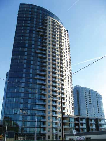
The Ardea
Portland, OR North-South Perimeters (Attachments Parallel to Deck Span) Note: Fasteners running parallel to the deck flutes is a severe condition and not recommended. If used, the following loading conditions occur. Line Load: Parallel to Deck Flutes The uplift pressure is 55.8 psf. The membrane area for the line load = (5 feet) = 5 square foot. Line Load on 1.0 foot of deck width = (5.0 feet)(55.8 psf)- 4.5 plf = 275 pounds per foot Positive moment = Mw = (0.08)wL2 = (0.08) (0.275 kips per foot)(6.0 foot)2 = 0.79 kip-feet = 9.50 kip-inches. Negative moment: Mw = (0.10)wL2 = (0.10) (.275 kips per foot)(6.0 foot)2 = 0.99 kip-feet = 11.9 kip-inches. For a uniformly loaded deck, the maximum negative moment is 2.22 kip-inches. Corner Condition Zone The uplift pressure is 84.0 psf for the first 10 feet from the building edge, and 55.8 for the remainder of the three span deck. Line load on 1.0 foot of deck width = [(5 feet)(84 psf)]/2-4.5 plf = 206 pounds per foot for first 10 feet. The division by 2 is to account for load distribution between fastener
lines. Then (5 feet)(55.8 psf)-4.5 plf = 275 pounds per foot beyond. Based on a continuous beam analysis, the maximum negative moment equals 11.55 kip-inches and occurs over the second interior support from the corner. The maximum positive moment occurs within the third span and equals 9.64 kip-inches. For a uniform load, the maximum negative moment equals 3.48 kipinches and occurs over the first interior support. The maximum positive moment occurs in the first span and equals 2.73 kip-inches. See Table for a summary of the conditions. Conclusions North-South Perimeters and Corner Zone failures occurred. It is interesting to note that, with the amounts of overload shown in these calculations, there are not more reported deck and joist failures. There may be a number of reasons for fewer reported failures. For example: 1) The design uplift anchorage of the deck to the joists, while increased for mechanical attachment as compared to adhered membranes, does not exceed the factors of safety in the design of the deck attachment fasteners. 2) The majority of roofs have not seen roof uplift loads of those predicted by ASCE 7 because the U.S. has not been impacted by a major hurricane in over 10 years. 3) The decks may have higher yield strengths than those used in the design example. The SDI RDDM tabulates roof deck capacity based on a lower bound yield stress of 33 ksi. Many manufacturers provide decks with yield stresses of 40, 50, or 80 ksi (limited to a 60 ksi design stress by the AISI S100 Standard). A design stress of 60 ksi versus 33 ksi will increase the deck flexural strength by about 70%.
Application When Re-Roofing
An important point to note is that, per NRCA, approximately two-thirds of the roofing installed every year is re-roofing of existing buildings. Buildings that are 20 to 30 years old are unlikely to have higher yield strength steel deck. Therefore, caution is required when evaluating roof deck when re-roofing.
Higher Wind Regions
The analysis described above was performed on a building located within the basic wind velocity zone of 115 mph per ASCE 7-10. Particular attention must be paid to the design of the deck for regions where the
Summary table of required deck strength to actual deck strength. Zone Moment Mr/φMp
Line Load, Mr or
(kip-inches) Mr /φMn
Moment Uniform Load, Mr (kip-inches)
Interior 4.851 0.95 1.242
East-West Perimeter 4.321 0.85 2.312
North-South Perimeter 11.92 2.22 2.222
Corner 11.552 2.16 3.482
1Positive moment, 2Negative moment. φMp = 5.088 kip-inches, φMn = 5.358 kip-inches Mr /φMp
or
Mr/φMn
0.23 0.43 0.41
0.65
wind velocity is higher. At higher design wind speeds, a deck which is adequate to support an adhered membrane roof with uniform uplift deck loading may not be structurally adequate to support widely spaced line loads from a mechanically attached membrane roof.
FM Global Requirements
Often times, FM Approval Standard 4470, Single-Ply, Polymer-Modified Bitumen Sheet, Built-Up Roof (BUR) and Liquid Applied Roof Assemblies for use in Class 1 and Noncombustible Roof Deck Construction, is required for roof systems. These requirements are more stringent with respect to deck spans and thicknesses because the FM Standard uses a Factor of Safety of 2, whereas the AISI S100 Standard mandates an ASD Factor of Safety of 1.67 for flexure. These requirements can be found on their RoofNav website. Go to www.roofnav.com and select Reference Materials followed by Approval Standards. The FM Standard provides wind ratings based on fastener row spacing, deck spans, deck thicknesses, and deck yield strengths. For the above example, for a 33 ksi, 1.5-inch. WR deck spanning 6 feet, a 20-gage deck is required to obtain a 60 rating (30 psf ASD).
Recommendations
Design recommendations for single-ply roofing when concentrated line securements are used to connect the membrane to steel roof deck instead of uniformly distributed securements include: 1) When FM Global requirements are to be followed, maximum deck spans, deck thicknesses, and deck yield strengths as required by FM Global must be used. a) Based on the maximum concentrated line loads determined from FM Global, specify the required joist net uplift. b) Coordinate your design requirements with the general contractor and the architect. 2) When FM Global requirements are not required: a) Determine the uniform net uplift forces based on the building code in force. b) Using the spacing between the lines of fasteners for the membrane, perform a structural analysis of the deck as a 3-span beam, placing the first concentrated load at the mid-span of the first deck span. The subsequent loads are placed according to their spacing. This analysis will produce a moment diagram that is close to the maximum that would be achieved from an influence line analysis. c) From this analysis, specify a deck that has a flexural capacity that exceeds the maximum positive and negative design moments. d) If no deck is found that will work, change the spacing of the supports (joists) or alter the spacing of membrane fastening. Changing the spacing of the membrane fastening is something that requires coordination with the entire roofing team (specifier, manufacturer, and installer). e) Determine the net uplift requirement for all joists based on the final selected line securement spacing and forces. f) Specify these requirements to the joist manufacturer. g) Coordinate your design requirements with the general contractor and the architect.
Economics
Based on experience, using the wide attachment spacing may not be economical when one considers the increase in deck costs and joist costs as compared to the labor savings using the wide securement spacing. For any given project, these cost comparisons should be made.▪


BRB MAST-FRAMES
An Improved Approach for Seismic Bracing

By Leo Panian, S.E.
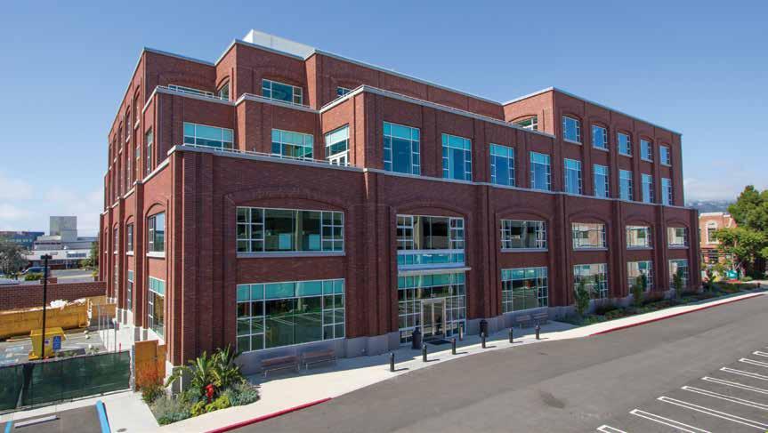
740 Heinz completed, as viewed from the southwest.
In recent years, engineers have been seeking to capture the bene ts provided by buckling restrained braces (BRBs) through the exploration of new braced-frame con gurations to improve the seismic performance of building structures. One such alternative is the BRB mast-frame system, which enhances seismic performance and o ers better architectural compatibility at a lower cost than conventional systems. e case study of 740 Heinz demonstrates the e cacy and cost e ciency of BRB mast-frames. Tipping Structural Engineers designed the BRB mast-frame system as a response to the disadvantages posed by conventional steel and BRBonly systems. is innovative approach consists of yielding BRBs in series, with a sti , elastic vertical frame (the “mast”) designed to pivot about its base. e mast redistributes loads between stories, producing a more uniform distribution of inter-story drift and eliminating the possibility of inelastic weak-story mechanisms.
740 Heinz Avenue
The Design Challenge
While there are economies in designing for lower seismic forces, the redundancy provisions of the building code can still require numerous bays of bracing, resulting in a signi cant number of BRBs. is, in turn, adversely a ects architectural programming and cost. Furthermore, BRBs’ reduced sti ness leads to larger building deformations, rendering a structure more susceptible to weak-story mechanisms. Ironically, these disadvantages come with a cost premium. e rst major application of the BRB mast-frame system was for the 740 Heinz building in Berkeley, CA. is state-of-the-art life sciences building is clad in precast concrete panels with brick veneer and has a footprint of approximately 136 feet by 192 feet, for a total of 110,000 square feet of gross area. e oor framing system consists of steel beams and girders supporting concrete- lled metal deck. Framing is supported by steel columns spaced at approximately 32 feet on-center in both directions. e seismic lateral-force-resisting system consists of two BRB mastframes in each direction. In the transverse, the frames are located next to the building’s stair cores; in the longitudinal, they are installed at the perimeter façade line. Each BRB mast-frame comprises yielding BRBs connected to a vertically oriented trusslike mast; a true pinned-base connection joins the frame and base. e structure was designed according to the provisions of the 2010 California Building Code; the frames were designed using an R of 7. e seismic analysis relied on a conventional code model response-spectrum method. e BRB mast-frame’s vertical-truss con guration is a key aspect of the design, as
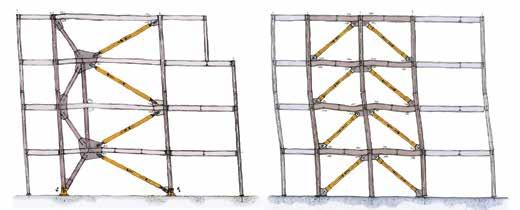
it can redistribute lateral loads between levels, eliminating soft-story mechanisms. The BRB mast-frame system relies on capacity-design principles to ensure that inelastic mechanisms will form predictably and reliably. To ensure controlled post-yielding response, the mastframe, including the base connections, anchor bolts, pile caps, and piles, was designed to resist amplified omega-level forces. The frame also allows for equal-capacity BRBs to be used at all levels, owing to the action of the mast, which simplifies construction. In contrast, a conventional code-designed braced frame, in responding to the lateral-force distribution, typically has the strongest BRBs at the base and the weakest at the top.
The Code Conundrum
The redundancy factor, ρ, was originally incorporated in the building code to prescriptively compel engineers to consider the number of the lateral bracing elements and their locations. ASCE 7 dictates that a braced-frame system is properly redundant if the number and arrangement of frames are such that the removal of any one brace in the system results in neither more than a 33 percent reduction in story strength nor an extreme torsional irregularity. Otherwise, the non-redundant structure must be designed with a 30 percent increase in the structure’s design base shear. While adding more frames in the building can eliminate the ρ penalty, this adds significant cost and does nothing to address the potential weak-story failure of the frames. To address this conundrum, Tipping developed the inherently redundant mast-frame configuration to meet prescriptive requirements and improve seismic performance, without the addition of lateral bracing elements.
Code Redundancy Analysis and Verification
To demonstrate that the BRB mast-frame system met ASCE 7’s redundancy prescription, Tipping created a three-dimensional analysis model to directly assess the performance of the frames with brace elements removed. Using this model, BRBs were systematically removed from each frame at each story to evaluate the redistribution of forces and calculate resulting deformations. The results revealed that the remaining BRBs and diagonal mast members in the modified structure were indeed able to resist redistributed forces. In the controlling case, story strength was reduced by 21 percent, 12 percent less than the codeallowed 33 percent reduction. Furthermore, the maximum story drift ratios did not exceed the limit of 1.4 times as required by ASCE 7.
The Promise of BRB Mast-Frames
The inherent redundancy of the system allows for fewer braced frames, improved seismic performance, and more economical construction. Employing BRB mast-frames at 740 Heinz allowed the number of required frames to be cut from seven conventional BRB frames down to 4 BRB mast-frames; the total number of BRB elements was reduced from 56 to 16. Moreover, because the BRB mast-frames were easily located next to the building’s two stair cores and at the perimeter façade, they did not impinge on the architectural space plan. Lastly, this lateral system saved the project $360,000 in construction costs when compared to a conventional BRB-frame system. In short, this system holds lots of promise for the future. It is a costefficient, nonproprietary, and simple high-performance system that can be designed in any number of possible configurations, making it an ideal lateral system for any steel braced-frame building.▪
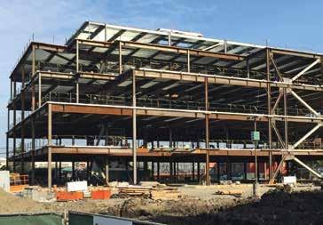
740 Heinz under construction.
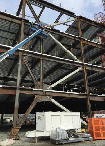
Close up of steel frame with BRB mast installed.
Leo Panian is a Principal at Tipping Structural Engineers in Berkeley, CA. He can be reached at l.panian@tippingstructural.com.
Tipping Structural Engineers was an Outstanding Award Winner for its 740 Heinz Avenue project in the 2016 NCSEA Annual Excellence in Structural Engineering Awards Program in the Category – New Building $10M to $30M.
Historic Renovation of the PROVO TABERNACLE
By Je Miller, S.E., Jesse Malan, S.E., and Julee Attig, CPSM
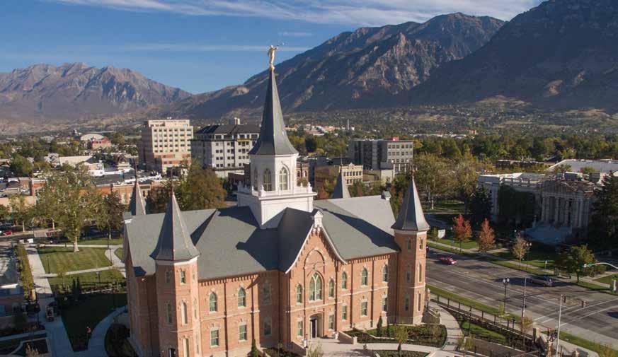
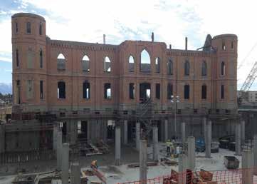
Constructed from 1883 to 1898, the Provo Tabernacle was a historical treasure of e Church of Jesus Christ of Latterday Saints (LDS) and the local community. It seated 1,500 and featured octagonal stair towers, a high-pitched gabled roof, art glass windows, exquisite woodwork, and a central tower topping out at 167 feet above the ground. e building hosted U.S. presidents, musical performances, school commencements, interfaith gatherings, and community events. A four-alarm re destroyed the building (Figure 1) in December 2010. e exterior was almost all that remained of the Tabernacle. Rather than demolish the structure, the owner enlisted a team of architects, engineers, builders, and historians to assist with an unprecedented reconstruction and restoration project. Reaveley Engineers + Associates (RE+A) was the structural engineering consultant. LDS Church leadership announced the Tabernacle would be rebuilt as a temple. Architecturally prominent, a temple is considered by members of the LDS Church as the most sacred place of worship. e structure serves a much di erent purpose than a chapel where regular worship services are conducted. is change in use would require the interior spaces be completely recon gured within the original building envelope to accommodate new building functions.
Challenges & Objectives
A signi cant challenge faced by the design team was converting a 35,000 square foot historic structure into a modern 85,000 square foot temple without losing historic details. A major excavation would be required to accommodate a basement and sub-basement below the original building, as well as adjacent sub-grade parking, doubling
Courtesy of Dustin Smith
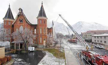
Figure 1. Crews respond to Tabernacle re.
the size of the building. In total, the contractor excavated to 25 feet below grade for approximately 170,000 square feet and 40 feet below grade for approximately 15,000 square feet. e team had one primary objective: limit settlement or another movement that could cause damage to the existing brick walls. Since the original building had only a crawlspace below the main oor, a system had to be engineered to support and reinforce the existing masonry walls for excavation to take place. e design and construction team explored several excavation and shoring methods that would support the original ve-wythe brick masonry walls while excavating two new sub-grade oor levels. A new internal bracing system would also have to be engineered to stabilize the remaining brick walls while the temporary external bracing system that was installed soon after the re was removed.
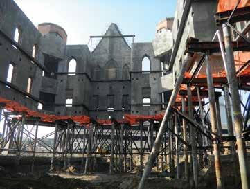
Figure 2. Shotcrete placed on interior face of the brick.
The design of the interior bracing system needed to be compact and maximize working space for the contractor. It also had to allow placement of new reinforced shotcrete walls against the interior face of the brick. This bracing system would remain in place until a new structural steel frame was constructed inside the building, and new floor and roof diaphragms were in place to brace the exterior walls. Selection of the shoring system was influenced by the presence of high groundwater at the site. The sub-basement level and lower part of the basement level would be located below the groundwater elevation. The proposed shoring system would need to ensure placement of the waterproofing membrane below the sub-basement floor and at the exterior face of the foundation walls without compromising the performance of the membrane under significant hydrostatic pressure.
Bracing/Reinforcing the Existing Masonry
Masonry Testing After the fire, tests were performed on the mortar in the brick walls and revealed minimal damage to the brick and mortar at the interior face of the walls. Most of the damage to the walls was caused by the collapse of the wood roof structure during the fire. Based on initial observations, it was evident that the mortar consisted of fine aggregate and lime, and was quite weak. Shear strength, compressive strength, and deformation property tests were conducted to assess the mortar’s physical properties. Results indicated the strength of the mortar fell below minimum thresholds. The brick walls did not have sufficient strength to function as shear walls or effectively resist out-of-plane earthquake forces. In short, the brick walls would need to be reinforced and strengthened. The Solution The original brick walls are anchored to new reinforced concrete shear walls by placing shotcrete against the interior surface of the brick (Figure 2). Two of the five interior wythes of brick (approximately 8 inches) were removed, and that space was replaced with shotcrete. Essentially, no floor space was lost. The remaining three wythes of brick were permanently anchored to the new shotcrete walls by installing 14-inch to 16-inch-long steel helical anchors into the brick. In the completed building, the shotcrete walls function as shear walls to resist lateral earthquake and wind loads imposed on the building. The walls also stabilize the existing brick walls against lateral out-of-plane forces.
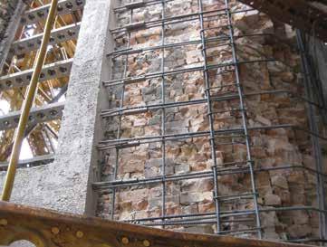
Figure 3. Care was taken with shotcrete placement around reinforcing steel.
Approach to the Work
In many areas, the need for thin concrete walls resulted in shear walls and boundary elements that did not comply with prescriptive code requirements. To help the owner gain confidence in the thinner walls performing as desired during an earthquake, the structural engineers completed a performance-based design using non-linear analysis techniques. The results indicated that the thinner shear walls would perform as prescribed to meet code requirements and the owner’s enhanced performance goal of life safety in the Maximum Considered Earthquake. Because of the reduced thickness, the quantity of reinforcing steel within the walls was greater than normal. Extra care was taken by the contractor to place the shotcrete in the walls while preventing voids behind and between the reinforcing steel. Enhanced inspections were conducted to maintain quality control of the shotcrete placement (Figure 3). Mechanical rebar couplers were placed at the bottom of vertical reinforcing bars within the shotcrete shear walls so that the bars could be extended into the top of the reinforced concrete foundation walls that were placed during a later phase of the project. After the brick walls had been reinforced and supported by the new concrete walls, steel beams were attached to the concrete walls creating a reinforcing horizontal “ring” near the elevations where new suspended concrete floors would be placed.
Excavation
With the masonry reinforced and strengthened, the next phase was to support the stabilized building shell so excavation could begin. The new composite walls would be supported by cased micro-piles while 30,000 cubic yards of earth were removed. A series of eight-inch diameter micro-piles were drilled into the ground, on each side of the walls, to a depth of about 90 feet. Some of the piles were battered to resist the temporary lateral loads on the shored walls during construction. Openings were then excavated through the rubble-stone foundation walls just below the brick and shotcrete walls. These openings were aligned between pairs of micropiles. Steel needle beams were placed through the foundation wall openings and connected to the micro-piles (Figure 4, page 40). Hydraulic jacks were placed between the needle beams and concrete bearing lugs formed into the bottom of the shotcrete walls. The jacks
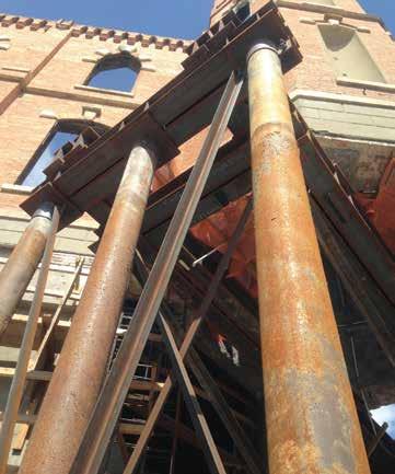
Figure 4. Steel needle beams connected to micro-piles.
were then loaded to transfer the weight of the walls above onto the needle beams and shoring system. The contractor closely monitored the elevation of the walls during this load transfer to ensure only very slight changes in the elevation. Once the weight of the walls was transferred into the shoring system, adjustable bearing seats were installed on each side of the jacks and the jacks were removed. Excavation of the surrounding soils then commenced with continued monitoring of the elevation of the structure. As excavation progressed, steel diagonal braces were added between the micro-piles to provide lateral stability and maintain the allowable unbraced length of the micro-piles.
Footings & Foundations
When the bottom of excavation was reached, a waterproofing membrane was installed and a new 18- to 24-inch thick reinforced concrete mat footing was placed. The new sub-basement level is
Demos at www.struware.com
Wind, Seismic, Snow, etc. Struware’s Code Search program calculates these and other loadings for all codes based on the IBC or ASCE7 in just minutes (see online video). Also calculates wind loads on rooftop equipment, signs, walls, chimneys, trussed towers, tanks and more. ($195.00). CMU or Tilt-up Concrete Walls Analyze solid walls for out of plane loading and panel legs next to or between openings by automatically calculating loads to the wall leg from vertical and horizontal loads at the opening. ($75.00 ea) Floor Vibration Program to analyze floors with steel beams and/or steel joist. Compare up to 4 systems side by side ($75.00). Concrete beam/slab Program to provide bending, shear and/or torsional reinforcing. Quick and easy to use ($45.00). Figure 5. Block-outs in foundation walls.
approximately 14 feet below the design groundwater elevation. The mat footing and foundation walls were designed to resist the upward hydrostatic pressures. The micro-piles served several purposes. First, they temporarily supported the exterior brick walls. Second, they served to support the mat footings for the heavy loads of the new structure. The micro-piles also helped mitigate the potentially liquefiable soils that exist on the site. Lastly, they acted as hold down anchors to resist buoyancy forces created by the water table. After the new mat footing had been completed, new reinforced concrete foundation walls were constructed between the mat footing and the bottom of the brick walls. Block-outs were formed in the foundation walls around each of the shoring needle beams (Figure 5).
New Superstructure
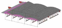
With the foundation system complete, the focus shifted to a new structural steel superstructure inside the shell of the existing building. The three new floor structures consist of composite steel beams supported by the new shotcrete exterior walls and interior steel columns. The reinforcing in the floor slabs was connected to dowels previously set in the shotcrete walls. The dowel system was designed to transfer forces between the walls and the floors, which serve as horizontal diaphragms while providing ductile behavior during an earthquake. The new sloped roof structure consists of a metal roof deck supported by steel beams. The structure was designed to support the weight and overturning forces imposed by a new center tower matching the pre-1917 original.
The restoration of this key architectural feature was of particular import to the owner (Figure 6).
Parking Garage
To the west and south of the Temple is a new single-level, sub-grade parking garage that connects to an adjacent parking garage. The lid structure over the parking area was designed as a post-tensioned concrete beam and one-way slab system. The typical span of the post-tensioned beams is 60 to 64 feet. Beam spacing varies but is typically about 27 feet-on-center. This structure supports a beautifully landscaped plaza. The weight of the landscaping overburden (18 to 35 inches of soil), pavements, snow, and plaza live loads combined to create significant loads on the lid structure.
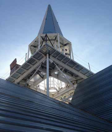
Figure 6. Restoration of center tower.
The concrete beams were designed with higher than normal posttensioning stresses to reduce beam depth as much as practical, while still controlling flexural cracking in the beam section. Careful detailing of the tendon anchorage plates was required to verify that they could fit within the profile of each of the beams. Grade 75 rebar was specified to reduce congestion of the steel reinforcing bars within the beams
Architectural Considerations
Restoring the building to its original state and preserving its historic fabric was a primary architectural objective for principal architect Roger Jackson of FFKR Architects. Preserving and stabilizing the original brick walls was an initial focus. Also of intense interest was restoring the original central tower. In 1917, the tower was removed because its weight caused excessive deflections in the roof members. The new tower is laterally supported by steel braced frames which transfer forces to the shotcrete shear walls through the roof diaphragm and supplemental bracing. Natural light streaming through windows around the tower illuminate an art glass ceiling in the main upper lobby located directly below the tower. Another significant architectural feature of the original Tabernacle was the wood-framed roofs of the octagonal stair towers at the four building corners (Figure 7). One stair was partially burned and damaged by the fire while the other three only suffered minor smoke damage. The tower roofs were each removed as a single piece, and the one damaged tower was rehabilitated and rebuilt to its original configuration. The original straight wood sheathing on the tower roofs was overlaid with new wood structural panel sheathing to stiffen and strengthen the roof structures. Connections between the base of the tower roofs and the walls below were improved to resist the required wind and earthquake loads.
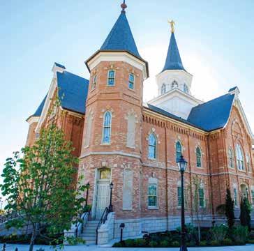
Figure 7. Wood-framed roofs at the four building corners.
Conclusion
The complex nature of this project demanded unique engineering and construction solutions. Dynamic, collaborative interactions between owner, architect, structural and geotechnical engineers, contractor and subcontractors generated economic and innovative solutions. “The contractors and architects have worked in similar situations where they have done underpinning but not at this scale and this height,” said LDS Church project manager Andy Kirby. “The design of this was a process between the architect, our design team, the structural engineers, and the contractors. We came up with multiple options, vetted those out, and then improved it to what you see now.” Many have called this historic renovation a “once-in-alifetime” project. The team understood what this project meant to the owner and community, and championed this vision from beginning to end.▪
Reaveley Engineers + Associates was an Outstanding Award Winner for its Provo City Center Utah LDS Temple project in the 2016 NCSEA Annual Excellence in Structural Engineering Awards Program in the Category – Renovation/Rehabilitation.
Jeff Miller, S.E., is a Senior Principal at Reaveley Engineers in Salt Lake City. He was the Principal in Charge and Project Manager on the project. In 2016, Jeff was recognized as the Utah Engineers Council’s Engineer of the Year. Jesse Malan, S.E., is an Associate at Reaveley Engineers. An active SEAU member, he has managed the structural design of the 220,000 square-foot research center expansion at Huntsman Cancer Institute. Julee Attig, CPSM, serves as Reaveley’s director of marketing. She serves on the board of directors for SMPS Utah. She can be reached at jattig@reaveley.com.
Wood Meets Structural, Aesthetic, and Sustainability Goals at One North
By Tony Cameron, P.E.
Viewed from the interior courtyard, One North’s intriguing façade incorporates exterior shading, an airtight insulated building envelope, and sustainably harvested, locally sourced cedar siding. Courtesy of Andrew Pogue.
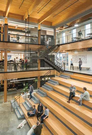
Glulam beams and columns and tongue-and-groove cedar decking were left exposed throughout the interior. Courtesy of Andrew Pogue.
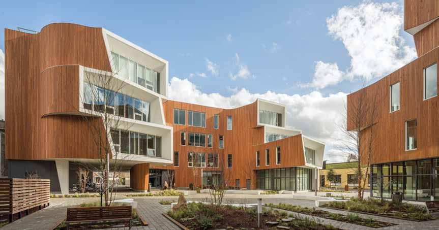
Much has been written about the One North development in Portland, Oregon. The two buildings, known as East and West, feature unique architecture, beyond-code energy efficiency, and a shared community courtyard. The project has received numerous awards for innovation and sustainability. However, behind the unique exterior lies a story. The team used glulam construction to meet a number of structural and aesthetic goals. “The most significant structural design challenge we faced with the project was due to the geometric demands of the buildings,” said Tim Terich, partner and principal in charge at Froelich Engineers, the structural engineers for One North. “The irregular shapes of the two buildings and the lateral systems that were spread throughout both required real collaboration between us, Holst Architecture, and R&H Construction. However, because wood is such a flexible and versatile material, we were able to make it work structurally and were also able to meet the owner’s aesthetic and sustainability goals.” The East Building stands four floors tall with 43,418 square feet. The structure features three floors of Type V-B wood-frame construction over a Type I concrete podium. The West Building has five floors and 35,671 square feet of space. This building has four stories of Type III-B wood construction over a Type I concrete podium. Both feature retail space on the first floor, with offices and creative space above. Terich explained that the interior of the East building has a large open area with stadium seating, which triggered the need to go to Type V construction. “The interior of the smaller West building did not have that, which meant it was more efficient for us to use Type III-B construction,” he said.
Wood’s Versatility Gave It the Edge
Both buildings have unique geometry, and Terich stated that they initially considered using concrete. “But, as we got into it, we knew we could not meet the architectural goals, which were sustainability and a desire to create a warm aesthetic. Concrete has a colder feel and it costs more, and wood is a better choice environmentally.”
ey also looked at using steel framing. However, with all the unique angles, steel would have required thousands of shop drawings, all of them unique. “Wood can be modi ed on site and is so much more a ordable,” added Terich. “So, we chose wood for multiple reasons. Number one was cost. Number two was the fact that wood is a renewable, sustainable material, which was a goal for the owner. And nally, the warmth and feel of the timber were a big driver for the architect. So we embraced the wood, and gave it a bit of a modern slant.” of 2-by-6-inch wood studs and wood structural panel shear walls for lateral loads. Stairs and elevators were also wrapped in wood structural panel shear walls. ey used continuous threaded rod hold-down systems. “We had to work around some staggered windows, but were able to sh them through in a few areas,” he added. Because the East building had a very complex geometry with some big openings in the diaphragm, Froelich engineers used rigid and semi-rigid diaphragm analysis. ey used the envelope technique to analyze the West building.
Timber Frame Functionality

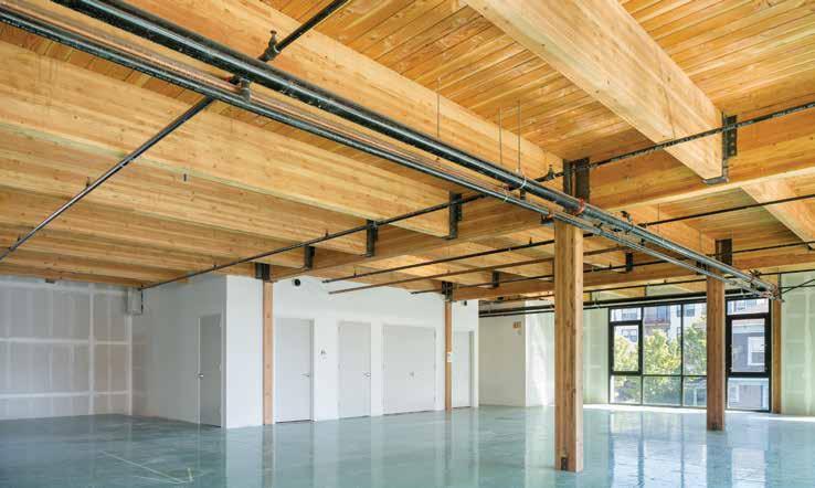
A concrete podium provided re separation, and allowed them to sup- Innovative Window Frames port the discontinuous loads that “didn’t want to stack and come down One of the most unique features of the project was provided by all the way through the building,” said Terich. Above the podium, the window frames, referred to as “apertures.” Both East and West they left the glulam timber frame exposed. Architectural grade glulam beams in 6¾- and 5⅛ -inch widths are supported by exposed glulam columns. A number of glulam beams were manufactured with one or two extra tension laminations for re resistance. “ is was a GEOPIER GROUND IMPROVEMENT compromise made with the city code o cials,” Terich explained. “We wanted to avoid CONTROLS STRUCTURE SETTLEMENT using automatic smoke curtains as much as possible and, by doing something as simple as adding one or two laminations to the beams, the code o cials felt more con dent about glulam performance in the event of a re. It was part of the compromise and solution to achieve that open area.” He added that the architect was also very interested in the aesthetic of the beam and column connections. “ ey did not want to use o -the-shelf connectors, even though they would have met code requirements. So, we spent a lot of time strategizing about connections. Most are concealed knife plate connectors, and some of them became quite complicated in places where we wanted to avoid showing exposed bolt heads or steel plates wrapping around the members. So, we tried to keep all the bearing elements hidden. e result was the clean but warm aesthetic that the architect wanted.”

Structural Considerations
One North was designed to the 2010 Oregon Structural Specialty Code, and Seismic Design Category D; seismic controlled the lateral in all cases. A mix of lateral systems was used. Above the podium, however, most were wood structural panel shear walls with a few custom moment frames. “We had to go with the moment frames because we did not have enough shear walls in some places, and we did not want to use any diagonal brace frames,” said Terich. Both buildings used conventional wood construction for the walls, which consisted
GIVE YOUR STRUCTURE STABILITY
Work with Geopier’s geotechnical engineers to solve your ground improvement challenges. Submit your project specifications to receive a customized feasibility assessment and preliminary cost estimate at geopier.com/feasibilityrequest.
800-371-7470 geopier.com info@geopier.com
The sprinkler system in the radiator places an individual sprinkler head near every exposed interior column. Courtesy of Josh Partee 2015.
buildings were modeled in 3D, and then the engineered prefabricated curved frames were attached. Some of the deep set windows were cantilevered, and others were not. The light gauge metal used in the prefabricated frames reduced weight by 60 percent over a steel solution and helped speed installation. “The actual primary wood structure of the building is more rectangular than it appears,” Terich said. “We used the apertures to make things easier and to add dimension. In some areas, we cantilevered the glulam to provide actual floor area; those are structural. However, in other areas, the metal aperture assemblies were simply bolted to the frame. I would say it is a 50/50 mix. Knife plates and tube steel spans between the floors allow the whole assembly to be attached. These apertures were then sheathed in wood structural panels. So, there is really a flat plane of structure and then the apertures, which change on every floor, cantilever off the grid.” Every material had its place. “We used the concrete where needed for the podium, and it worked well there,” said Terich. “We could have built the apertures with wood, but the pre-engineered systems were so easy. We just covered them with wood structural panels to achieve that exterior geometry. Then we exposed the glulams to provide interior warmth.” He said they were able to achieve their goals both outside and in. “We got that warm wood look with some modern connections and were able to maintain the integrity of the architectural and sustainability goals while getting the structure to work. It required close collaboration between us, the architect and the builder, but we were all committed to the details. In the end, we were able to meet an extensive variety of goals, in large part because wood is so adaptable.”▪
Constructability of Wood
Terich said his biggest surprise came in how easy the two structures were to build. “It is a beautiful but relatively challenging design, so I thought the contractor would have their hands full,” he said. “There were so many elements – the concrete podium, the wood frame, and the metal stud aperture assemblies. I thought it would take longer to build, but R&H Construction brought some real craftsmanship to the table and got it all to fit smoothly.” From an engineering perspective, Terich said it was a satisfying challenge working with the variety of materials to achieve the goals of the building. “I was not sure we would be able to pull off the geometry of these buildings until we really got into it,” he said. “But wood is so adaptable, which is exactly what we needed when we had to tie into some of the less adaptable elements, such as the moment frames and the tube steel columns which support various areas.”
Project Teams
Radiator Team Developer: Kaiser Group, Inc. Structural: Munzing Structural Engineering Architect: Path Architecture
One North Team Developers: Karuna Properties II, LLC; Nels Gabbert, LLC; Owen Gabbert, LLC Structural: Froelich Engineers Architecture: Holst Architecture
Tony R. Cameron, P.E., is a Staff Engineer at APA-The Engineered Wood Association. He can be reached at Tony.Cameron@apawood.org.
STEEL CONSTRUCTION
Companies Improve Products to Keep Up with User Demands
By Larry Kahaner
Steel users are demanding changes and companies are responding with updates, enhancements, and new products. Amber Freund, Vice President – Operations at RISA Technologies (www.risa.com), says that the company’s software receives new features on a frequent basis. “With regards to recent steel-related improvements, the latest releases added the ability to get both analysis and code checks for cold-formed steel face-to-face and tube members,” she says. “Our staff, composed of structural engineers, researched a number of codes and white papers to provide this ability. We added this feature after receiving requests from users who wanted to use face-to-face cold formed shapes but couldn’t find examples of how to calculate their capacity.” Another major new feature is baseplate design within RISAConnection. Says Freund: “For years we have had users asking for the ability to get baseplate design for their RISA-3D models without needing to enter the forces into another program manually. By providing full integration between RISAConnection and RISA-3D, the forces are automatically transferred, and you can now get baseplate design for your RISA-3D models on a Per-Load-Combination basis. This ability means that your baseplate and anchor bolt forces are much more accurate than using envelope forces, giving you the most realistic and economical baseplate designs.” As for industry trends, Freund sees an increased reliance on software to do engineering calculations. “This is a trend that has been ongoing for at least 20 years, and we see no end in sight. Project schedules no longer afford engineers the time to do hand calculations, and permitting officials now require rigorous 3D analysis for many structures that hand calculations were previously considered adequate,” says Freund. (See ad on page 84.) ClarkDietrich Engineering Services (www.clarkdietrich.com) officials would like SEs to know about their TrakLoc Drywall Framing System. The system offers multiple assemblies including the TrackLoc Fixed Length Stud (TLF), the TracLoc Adjustable Stud Assembly (TLA), the TrakLoc Deflection Stud Assembly (TLD), and the TrakLoc Elevator Stud (TLE), according to Chad Casbon, Director of Engineering. “Each system offers the benefit of a snap and lock connection between the top/bottom track and each stud that does not require screws. Also, they all allow installation from the floor, eliminating the need for lifts which saves time and money. We see an increasing number of circumstances where long-length studs need to be stocked in high rise buildings without the problems associated with closing streets and using cranes, for which a major component is cost. Traditional cold-formed steel members can be spliced, but that requires engineering, more labor, and unknown performance in terms of stiffness. TrakLoc offers a pre-engineered solution with minimal labor and is backed by testing that ensures an expected performance. I would suppose that most engineers are not aware of some of these logistical job site problems nor are they likely familiar with potential solutions like TrakLoc.” The company highlights its involvement with the new Sacramento Kings Arena, the Golden 1 Center, which included 65,000 linear feet of metal stud wall framing. “The project included unique challenges that were solved through collaboration with the framing contractor. One such challenge was the construction of 48-foot tall exterior wall panels that were erected and stacked in a 22-inch wide cavity between the new building and an existing building. All metal stud members were pre-measured and pre-cut to minimize waste and maximize efficiency.” Casbon adds: “Another design challenge was the free-standing, self-supporting concession stands with cantilevered canopies framed completely out of cold-formed steel members. All seismic design requirements that are typical in California were satisfied without the addition of more expensive hot-rolled steel members.” “Through the use of BIM, creative engineering, and collaboration, ClarkDietrich Engineering and the other design team members were able to maintain the open space nature of the Arena without compromising any of the desired systems. These efforts resulted in the completion of this fast-paced, high-profile project on time,” Casbon says. Stuart Broome, Business Manager for Engineering at Trimble Solutions (www.tekla.com/us), says that Tekla Structures has been the chosen software solution for steel detailers around the world for many years but more recently has become popular with other disciplines, especially structural engineers. “The fact that it can be used for construction documents as well as shop drawings makes it


very appealing to structural engineers, and its ability to model in any material, including cold formed, means that it is extremely versatile.” As for new versions, Broome says: “Tekla Structures 2017 has many enhancements, especially in the areas of rebar modeling and drawing production. I expect that Tekla Structures will continue to gain momentum as the structural engineer’s BIM solution of choice because of the ability to work to a high level of detail and pass valuable information downstream. Structural engineers appear to be getting more interested in producing ‘truly constructible’ models rather than ‘design intent’ models which can often be open to interpretation. Tekla Structures does this well, without much additional modeling time and without the model size becoming unwieldy.” Broome also notes that Tekla Structural Designer (TSD – Trimble’s analysis and design solution) has seen many improvements and additions in the last 12 months. “The one that has been most well received is the ability to model and design a wide variety of foundations. Pad footings, strip footings, pile caps, and raft foundations are all now included,” he says. “However, it is the ability of TSD to work so well within the BIM environment that is continuing to drive our business. TSD 2017 continues to deliver in this area whether you are using Revit or Tekla Structures as your BIM platform. The fact that TSD is a physical modeling solution rather than a traditional ‘wire frame’-based analysis tool make this integration very easy for us to provide.” More enhancements are part of Tedds 2017, including code updates. “Tekla Tedds has always been a favorite of our clients. However, now that Tedds has been available in the U.S. market for some years, our clients are starting to venture beyond the component calculations included in the structural calculation library and are now using Tedds as it was originally intended–as a total calculation production suite.” Adds Broome: “Tedds includes code tables, code graphs, section data, section property calculator, 2D frame analysis, and the ability to write electronic calculations in an MS Word environment. Structural engineers appear to be placing value on the capacity to produce, submit, and archive all of their structural calculations electronically. We expect this trend to continue.” How’s business? “ I say this every year,” Broome adds, “and I can say it again this year – business has never been better. I have seen a huge shift in attitudes to new technology over the last five or six years. Structural engineers seem to be moving from being afraid of change to now striving for improvement. The race to be the most productive and competitive is on, and we think our clients have the best chance of winning that race. We look forward to sharing in their success.” (See ad on page 3.) Ben Follett, U.S. Product and Marketing Manager at Nemetschek (www.nemetschek.com/en), is also weighing in with his company’s updates. “Our version 17 release is planned for May. With that release will come updates to all the steel-related codes, updates for
ADVERTISEMENT–For Advertiser Information, visit www.STRUCTUREmag.org

3D Finite Element Design Software for Complex Geometry

© HGA Architects and Engineers
Contact us today to learn more at usa@scia.net
SCIA Inc., 7150 Riverwood Drive, 21046 Columbia, United States, +1 443 671 1431, www.scia.net


the AISI code, as well as updates for the AISC 360 codes. We also have a project for composite improvements that will nalize or solidify our work for composites based primarily on user feedback and user beta testing. e hope is that we are providing users the composite work ow that they have been asking for and we have been trying to achieve,” he says. He notes that the company has always been customer driven and will remain so. “ at is our number one goal. We answer questions within the same day for all of our customers. On the developer side, we truly only develop based on customer feedback,” Follett says. “If there are things that need to be added or need to be changed, or if our priorities are one thing but our customer or group of customers or group of potential clients think that they should be another, then obviously we are going to be very open to making that.” For the future, Follett sees the continuing interest in interoperability not only between the architect and the engineer but between the engineer and the fabricator. “I think that is going to play a critical role going forward. Trying to determine how to better exchange data or models is important because we often spend much time and money on change orders during the construction phase. A lot of that could be mitigated by having better coordination and cooperation between the engineer and the fabricator, and ultimately the contractor.” Nick Decker, the Senior Industry Specialist at Bluebeam, Inc. (www.bluebeam.com), says the company takes great pride in partnering with customers to create new features and ne-tune work ows that eliminate the tedium of repetitive, time-consuming tasks. at optimizes collaboration and work ow e ciency. “Every new iteration of Bluebeam Revu grows with and responds to the evolving work ow needs of our customers. Structural engineers use Revu every day to expedite reviews and preserve value,” he says. “Bluebeam Revu delivers enhanced PDF-based takeo and work ow automation tools that span the entire project lifecycle and maximize work ow e ciency, making for a powerful end-to-end solution. “ e Batch Markup Summary feature in Revu 2016 allows the project team to produce a single comprehensive report detailing the changes made across an entire document set. With expanded data sorting and ltering capabilities, running multiple reports in both PDF and Excel formats is easier than ever.” Decker adds: “ e Legends feature enables engineers to visualize the markup data directly on the PDF, which was a highly requested work ow enhancement. By summarizing the markup data in a customizable table, the legend on the PDF automatically updates in real time, providing the user with data at a glance.” Decker notes that Bluebeam Revu is used by customers in more than 100 countries. He says: “Bluebeam Revu is used by 94% of top US contractors, 86% of top U.S. design rms, 92% of top designbuild rms, 74% of top international design rms, and 78% of U.S. specialty contractors. Bluebeam was also ranked as one of the nation’s fastest growing technology companies by Deloitte Technology Fast 500 three years in a row.” As for what trends he is seeing, Decker says that project teams are becoming more dynamic, handling more projects across increasingly larger geographical areas. “Having an open, lightweight platform on which to collaborate with team members across the globe has become a necessity and not a luxury. Beyond that, engineers and designers are wearing more hats than ever and utilizing more software solutions to complete their daily tasks. To expedite those work ows across independent systems, engineers are requesting systems talk to each other, and that le types be viewable and editable across multiple software platforms. is explains the rise of APIs for system integrations and open le formats, like IFC.” According to Carlos de Oliveira, P.Eng, co-founder and President of Cast Connex Corporation (www.castconnex.com), headquartered in Toronto, Ontario, architecturally exposed structural steel (AESS) is omnipresent in modern airports. e company is currently supplying components for Austin–Bergstrom International Airport and Charlotte Douglas International Airport, and has in the past supplied castings for airports from coast to coast to coast – from critical structural elements in the seismic-retro t of Oakland International Airport to its Universal Pin Connectors and Architectural Tapers used at the ends of AESS braces in Bangor International Airport. In Austin–Bergstrom International Airport designed by Gensler and Architectural Engineers Collaborative, CAST CONNEX® Universal Pin Connectors™ are used at the ends of key AESS elements on the exterior of the new terminal expansion, while custom designed castings support AESS roof trusses spanning 90-feet across the terminal. For the Charlotte Douglas International Airport Concourse A Expansion project, CAST CONNEX provided pre-tender concept development support to Perkins+Will, C Design, and Stewart Engineering, and is supplying design-built custom cast steel column bases that not only provide re- and blast-resistant structural supports for the 145-foot long roof trusses, but are also a key part of the new building’s architectural expression. “While educational, cultural, and commercial projects continue to be our company’s ‘bread and butter,’ airports and transit terminals are sectors where steel castings can ex their structural and architectural muscle,” says Carlos. “It is in those large scale projects where we get to push the boundaries in terms of providing highly integrated elements that are critical to both the structural performance of the buildings as well as to their overall architectural quality.” ( See ad on page 2.)▪