

Acquisition in Augusta, Southern States returns to its roots PAGE 7 T O D A Y www.H 2 S0 4 Today.com Spring/Summer 2024 COVERING BEST PRACTICES FOR THE INDUSTRY IN THIS ISSUE > > > > Market Outlook: What lies ahead? PAGE 10 The importance of pump maintenance PAGE 18 Troubleshooting exchangers: design, maintenance & supply challenges PAGE 24 Sulfuric Acid Y E A R S C E L E B R A T I N G 1994 2024 30


YOUR PATHWAY TO A CLEANER FUTURE
Driving sustainability and carbon neutrality, MECS specializes in sulfuric acid and environmental technology processes for non-ferrous metal, fertilizer and chemical industries. As a world leader in optimized solutions for carbonless energy generation, smelter air pollution control, oleum & sulfur trioxide production for e-grade acid in support of semiconductor manufacturing, high-efficiency mist elimination for green hydrogen processes, and much more, we are on the leading edge of technology advances for a cleaner tomorrow. Contact

our experts today. MECS.ElessentCT.com

Sulfuric Acid
Vol. 30 No. 1 Covering Best Practices for the Industry Spring/Summer 2024
Dear Friends,
Welcome to the Spring/Summer 2024 issue of Sulfuric Acid Today magazine. This issue celebrates 30 years of covering the products, technology, and people that shape our industry. While we’ve seen many changes over the past 30 years, one thing that never changes is the dedication to excellence and innovation we see, day in and day out. The Sulfuric Acid Today team and I look forward to highlighting it for many years to come!
In this issue, we have several informative articles regarding state-of-the-art technology and projects. Our cover story focuses on Southern States Chemical’s recent addition of a sulfuric acid manufacturing facility in Augusta, Georgia, and the teamwork to bring the plant online (page 7), Acuity Commodities explains the impact of Morocco on the acid import market, how freight issues due to the drought in the Panama Canal effectively cut off some markets, and how sufficient supplies from Asia were driven by market conditions (page 10); Branham Industrial explains how 100 percent radiography provides physical evidence of any defects, imperfections such as voids, porosity, cracks, incomplete fusion, and lack of penetration within the weld zone (page 16); Weir Lewis Pumps shares their knowledge of pump maintenance and how it can be broken down into four basic categories: emergency, routine, preventative, and predictive (page 18); Spraying Systems explores key innovations in sulfuric acid handling, sulfur gun design, and diverse nozzle designs, highlighting their

transformative impact on industrial operations (page 20); INTEREP explains if tie rods (also called control rods) on their expansion joints can absorb pressure thrust (page 22); NORAM Engineering & Constructors delves into exchanger troubleshooting, design, maintenance and supply challenges (page 24); Beltran Technologies shares their wet electrostatic precipitator technology for sulfuric acid plants (page 30); Chemetics’ stainless steel radial flow converter celebrates 40 years of innovation (page 32); and Clark Solution explains the importance of in-line dilution with CFD-supported analysis (page 34).
I would like to welcome our new and returning Sulfuric Acid Today advertisers and contributors, including: Acid Piping Technology Inc., Acuity Commodities, Alphatherm, BASF, Beltran Technologies, Branham Industrial, Central Maintenance & Welding, CG Thermal, Chemetics, Christy Catalytics, Clark Solutions, Elessent MECS Technologies, LacMac GORE-TEX, INTEREP, Knight Material Technologies, Mercad Equipment Inc., NORAM Engineering & Constructors, Southwest Refractory of Texas, Spraying Systems Co., VIP International, and Weir Minerals Lewis Pumps.
We are currently compiling information for our Fall/ Winter 2024 issue. If you have any suggestions for articles or other information you would like included, please feel free to contact me via email at kathy@h2so4today.com. I look forward to hearing from you.
Sincerely,
Kathy Hayward


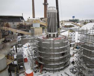
Acquisition in Augusta, Southern States returns to its roots PAGE 7 T O D A Y www.H S0 Today.com Spring/Summer 2024 COVERING BEST PRACTICES FOR THE INDUSTRY IN THIS ISSUE > > Market Outlook: What Lies Ahead? Troubleshooting exchangers:
Y E S C E L E A T N G 1994 2024 30
Sulfuric Acid
FROM THE PUBLISHER On the Cover… 7 Southern States Chemical (SSC) recently added a sulfuric acid manufacturing facility in Augusta, Georgia to its inventory of production sites. Departments 4 Industry Insights News items about the sulfuric acid and related industries 12 Safety Sector Sharing common safety concerns 14 Lessons Learned Case histories from the sulfuric acid industry 16 Product News Latest sulfuric acid technology 28 People on the Move Announcements regarding industry professionals 36 Faces & Places Snapshots from industry events 38 Calendar of Events Upcoming industry meetings 10 What lies ahead? 16 Radiography of full penetration welds in flex hose for safety and reliability 18 The importance of pump maintenance 20 Innovations in sulfuric acid handling for enhanced efficiency and safety 22 Can I really “absorb” pressure thrust with tie rods/control rods? 24 Troubleshooting exchangers: design, maintenance & supply challenges 30 Wet electrostatic precipitator technology for sulfuric acid plants 32 Chemetics’ stainless steel radial flow converter: celebrating 40 years 34 In-line dilution of sulfuric acid: CFD-supported analysis PUBLISHED BY Keystone Publishing L.L.C. PUBLISHER Kathy Hayward EDITOR April Kabbash EDITOR April Smith MARKETING ASSISTANT Tim Bowers DESIGN & LAYOUT 281-545-8053 Mailing Address: P.O. Box 3502 Covington, LA 70434 Phone: (985) 807-3868 E-Mail: kathy@h2so4today.com www.h2so4today.com SUBSCRIPTIONS U.S. Addresses Only Subscribe Online: www.h2so4today.com FEATURES & GUEST COLUMNS 18 32 24
T O D A Y
Kamoa-Kakula Copper
Complex partners with Elessent for MECS® sulfuric acid plant
ST. LOUIS—The Kamoa-Kakula Copper Complex (Kamoa-Kakula), a joint venture between Ivanhoe Mines, Zijin Mining Group, and the government of the Democratic Republic of Congo (DRC), has partnered with Elessent Clean Technologies (Elessent) to install a new 2,500 metric tonne per day (MTPD) smelter off-gas MECS® sulfuric acid plant. In conjunction with global EPC partner, China Nerin Engineering Co. Ltd. (NERIN), the new acid plant will be part of a new 500,000-tonnes-per-annum directto-blister flash copper smelter that is under construction at Kamoa-Kakula, as part of its Phase 3 expansion. Upon completion of the Phase 3 expansion, Kamoa-Kakula is projected to be the fourth largest copper operation globally.
“At Kamoa-Kakula we aim to set a new industry standard by being the greenest major copper mine in the world. It helps that DRC not only has an incredible mineral endowment, but also has an abundance of clean hydroelectricity to power its mining industry. However, we also need the right technology to extract the copper in a sustainable way. By using the MECS® acid plant design and its incorporated technolo-
gies, our new plant helps achieve our path to net zero,” said David Mitchell, KamoaKakula’s Senior Project Manager for the smelter project.
The MECS® sulfuric acid process incorporates state-of-the-art technologies, such as MECS® pre-conversion technology and MECS® DynaWave® gas cleaning technology. DynaWave® scrubbers, the gold standard in gas cleaning applications, clean and condition upstream off gas of the smelting furnace at the sulfuric acid plant. The MECS® pre-conversion technology is a novel approach for processing off-gas streams with elevated sulfur-dioxide concentrations while consuming significantly less power.
“Kamoa-Kakula is one of the world’s fastest-growing major copper operations. Partnering with NERIN on the mine’s greenfield smelter complex is very exciting. It is a great honor to work with the owners of what is anticipated to be one of the greenest major copper operations on the planet,” said Eli Ben-Shoshan, CEO, Elessent Clean Technologies.
The Kamoa-Kakula Copper Complex has been in commercial operations since July 2021. The operation is currently undergoing its Phase 3 expansion, which will increase copper production to over 600,000 tons of copper per year from Q3 2024.
The MECS® sulfuric acid technology has been in use for nearly a century in phosphate fertilizer, non-ferrous metals
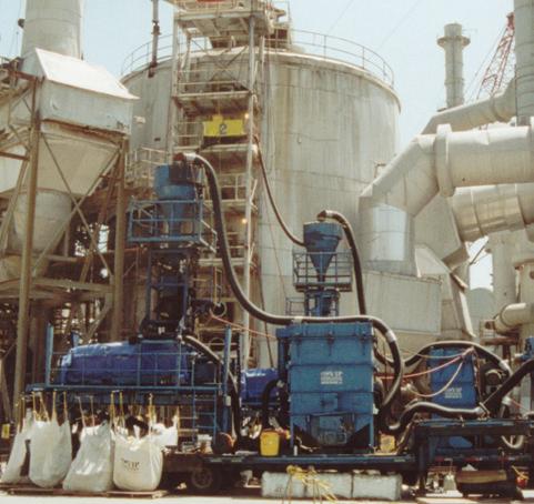
For the past 30 years VIP International has led the industry in innovative equipment and procedures in maintaining sulfuric acid plants. As the industry demands longer run times between catalyst screening, VIP’s patented catalyst handling system ensures the longest run time with lowest pressure drops to ensure maximum performance of your converter. Contact VIP International to learn how to reduce your downtime and increase your production and on stream factor.

(leaching & smelting), oil refining, and general chemical industries. MECS® technologies feature breakthrough solutions, many of which have revolutionized the performance, quality, and cost-effectiveness of customer operations. They include MECS® heat recovery systems (HRS™), MECS® SolvR® regenerative SO2 scrubbing and MECS® MAX3™ sulfuric acid production technology. Integrated into these MECS® technologies are proven specialty products such as catalysts, Brink® mist eliminators, DynaWave® scrubbers, ZeCor® corrosion resistant alloy products, and acid coolers, all of which are specifically designed for the most demanding operating environments.
Marketed by Elessent Clean Technologies, MECS® sulfuric acid technology is used in more than 1,000 sulfuric acid plant licenses and projects worldwide. For more information, visit www.ElessentCT.com.
Ma’aden partners with Metso and thyssenkrupp Uhde for recycling and CO2 capture
RAS AL KHAIR, Saudi Arabia—Saudi Arabian Mining Company (Ma’aden), the largest multi-commodity firm in the Middle East, has signed a frame agreement with Metso and thyssenkrupp Uhde for the development and licensing of a phosphogypsum processing solution for the calcination plant at Ras Al Khair in Saudi Arabia.
ing. Metso will contribute to the project with our extensive expertise and experience in the field of fluid bed, gas cleaning, and sulfuric acid solutions,” said Hannes Storch, Vice President for Metals and Chemicals Processing at Metso. For more information, visit www.metso.com. For more information about the project, visit www.maaden.com.sa.
Topsoe to supply technology for Euro 360m carbon capture project
LYNGBY, Denmark—Topsoe has been selected by Essar Oil UK to be a technology licensor for its carbon capture facility, based in Stanlow, North West England.
Topsoe will deliver its SNOX™ technology for the removal of nitrogen oxides, sulfur dioxide, carbon monoxide, dust and other contaminants from the flue gas emitted in the production process. Topsoe’s technology will be one of a number of integrated licensed solutions supporting Essar’s plant, and will contribute to reducing their CO2 footprint.
Elena Scaltritti, CCO, Topsoe, said “We are thrilled to have been chosen as technology licensor for Essar Oil UK and support them in meeting their decarbonization targets. The agreement represents a landmark step for Topsoe’s development in the United Kingdom, and we look forward to working with Essar on this important project, which is a great example of how the fossil industry can decarbonize itself.”

The plant will use sulfur for the calcination of phosphogypsum and include technologies for CO2 capture with lime produced from the calcination. The process will lead to a reduction in CO2 emissions across Ma’aden’s phosphate business, making it more sustainable in the long term. Ma’aden’s patented concept will allow the company to use new technology to reduce carbon emissions and recycle phosphogypsum into a useful resource. Metso’s role in this development is to provide technology knowhow for this unique process.
Hasan Ali, Executive Vice President, Ma’aden Phosphate, said, “This pioneering patent, combined with our new CO2 capturing complex, underscores Ma’aden’s commitment to sustainability. We look forward to working with Metso and thyssenkrupp Uhde to develop this important project that will truly change and reduce the carbon footprint of our phosphate business. It puts us at the forefront of innovation, turning what was once leftover material into a valuable resource, while significantly reducing CO2 emissions. It’s a giant leap towards a sustainable future.”
“We’re excited to see this unique project moving forward. The new concept for the phosphogypsum processing will be a major step forward in the fertilizer industry, contributing to sustainability targets, such as waste recovery and limiting global warm-
Deepak Maheshwari, CEO of Essar Oil UK, said “We are ready to move into the next phase of Essar Oil UK’s decarbonization strategy. With an investment of USD 1.2 billion, Essar Oil UK is positioned to be the world’s first low carbon refinery. The industrial carbon capture facility, combined with our upcoming hydrogen fuel switching project, will reduce the refinery’s CO2 emissions by 95%. Topsoe is a valuable partner in this endeavor. With Topsoe’s SNOX™ technology we are getting a well proven and highly sustainable flue-gas treatment.”
With SNOX™ technology, refineries, power plants, carbon black manufacture can remove sulfur dioxide, nitrogen oxides, carbon monoxide, particulates, and other contaminants from flue gases. The sulfur is recovered in the form of commercial grade concentrated sulfuric acid. The SNOX™ process works without any consumption of water and limestone, and without generating any waste or ocean discharge. For more information, visit www.topsoe.com.
Chinese group to buy Dundee’s Namibia smelter
ONTARIO—Canadian miner Dundee Precious Metals (DPM) will sell its Tsumeb smelter, in Namibia, to Sinomine Resources for $49 million in cash. Tsumeb is one of the
6638 Pecue Lane, Baton Rouge, LA 70817-4400 | www.vipinc.com 225-753-8575
INSIGHTS PAGE 4 Sulfuric Acid Today • Spring/Summer 2024 Department
INDUSTRY
few smelters globally that can treat complex polymetallic concentrates, including those with higher arsenic content. It produces blister copper (98.5% copper), which is refined in Europe and Asia, and sulfuric acid as a by-product.
DPM bought the smelter in 2010 to secure a processing outlet for the concentrate produced by its Chelopech mine, in Bulgaria. However, with developments in the global smelting market and changes in the quality of Chelopech concentrate, DPM can now place its concentrate at several other third-party facilities.
“We are extremely proud of the investments that we have made to transform Tsumeb’s operational and environmental performance into a specialized custom smelter with a highly skilled workforce,” said CEO David Rae.
The transaction is subject to customary closing conditions, including approval under the Namibia Competition Act and approvals required from Chinese regulatory authorities for overseas investments, and is expected to close in the third quarter.
For more information, visit www.dundeeprecious.com.
Zimplats’ $1.8 billion projects on course
GUERNSEY, United Kingdom—Zimplats, Zimbabwe’s largest platinum producer, says all major capital projects implementation progressed according to plan in the quarter ending December 31.
Zimplats capital projects are expected to be completed by 2028 and are part of the miner’s $1.8 billion expansion plan, which includes the development and upgrade of two new mines.
In its quarterly report for the period ending December 31, 2023, the mining entity noted that it has to date spent $1 million on the implementation of the 35MW solar plant project with $35 million committed as of December 31, 2023, against a budget of $37 million.
“This is the first of the project’s four phases, which will be implemented at an estimated total cost of $201 million to generate 185MW,” the report said.
Zimplats has already started the construction of a 185MW solar plant to power up its operations. During the first phase, the company is gearing up to install 35MW of solar capacity at the Selous Metallurgical Complex. This initial phase is expected to cost $37 million. The entire project, estimated to cost $201 million, is expected to be completed in 2027. The firm now directly imports up to 70 megawatts from Zambia, ensuring stable operations and potentially boosting production.
Last year, Zimplats signed a direct import power agreement with the Zambia Electricity Supply Company (Zesco), resulting in improved power stability and availability.
Another major project is the smelter expansion and SO2 abatement plant project. To date, $220 million has been spent with a further $187 million committed against a total project budget of $521 million.
It added that $18 million has been used on the Base Metal Refinery refurbishment project with a further $16 million committed, against a total budget of $190 million.
Zimplats base metal refinery project resonates with the Government’s thrust on mineral beneficiation. The Government has over the years been exploring possible methods of ensuring the beneficiation of minerals, with policies targeting mostly platinum, diamonds, gold, and chrome mining with the intention to unlock the full potential of the mining sector.
On production update for the period, mining volumes benefited from pillar reclamation operations at Rukodzi Mine and the continued ramp-up in production from Mupani Mine, which is under development.
“This resulted in ore mined increasing by one percent and four percent from the prior quarter and the prior year’s comparable period respectively,” the report said. Increased tonnes from pillar reclamation bolstered the 6E head grade, which increased by one percent from the prior quarter and was stable year-on-year. It noted that ore milled was in line with mined volumes in the period and was stable quarter-on-quarter and year-on-year, with the concentrator plants performing at expected throughput rates.
For more information, visit www.zimplats.com.
Adani to open $1.2bn copper refinery in Gujarat, India
GUJARAT, India—Adani Enterprises, a subsidiary of Kutch Copper, is advancing with its greenfield copper refinery project in Mundra, Gujarat. The $1.2bn facility, poised to be the world’s largest single-location copper manufacturing plant, will commence its first phase by the end of March.
It is expected to reach a full one million tonnes per annum (mtpa) capacity by FY 2029. Set to bolster India’s copper production capabilities, the project will significantly reduce the country’s reliance on imported copper and support its energy transition efforts.
According to sources familiar with the development, the first phase of the project will have a capacity of 0.5mtpa.
The plant is designed to produce not only copper cathodes and rods but also byproducts such as gold, silver, selenium, and platinum.
The integrated complex will also manufacture sulfuric acid, a crucial raw material for various industries, including fertilisers and chemicals. India currently imports around 2mtpa of sulfuric acid.
For more information, visit www.adanienterprises.com. q


INDUSTRY INSIGHTS
Sulfuric Acid Today • Spring/Summer 2024 PAGE 5 Department
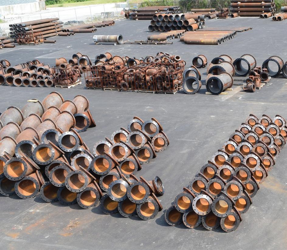
MONDI™ Pipe and fittings
- MONDI™
- Teflon Lined Piping
- Pipe Hangers
- Bolts
- Gaskets

Tower & Converter Internals
- MONDI™ Distribution Systems
- MEEHANITE Converter Internals
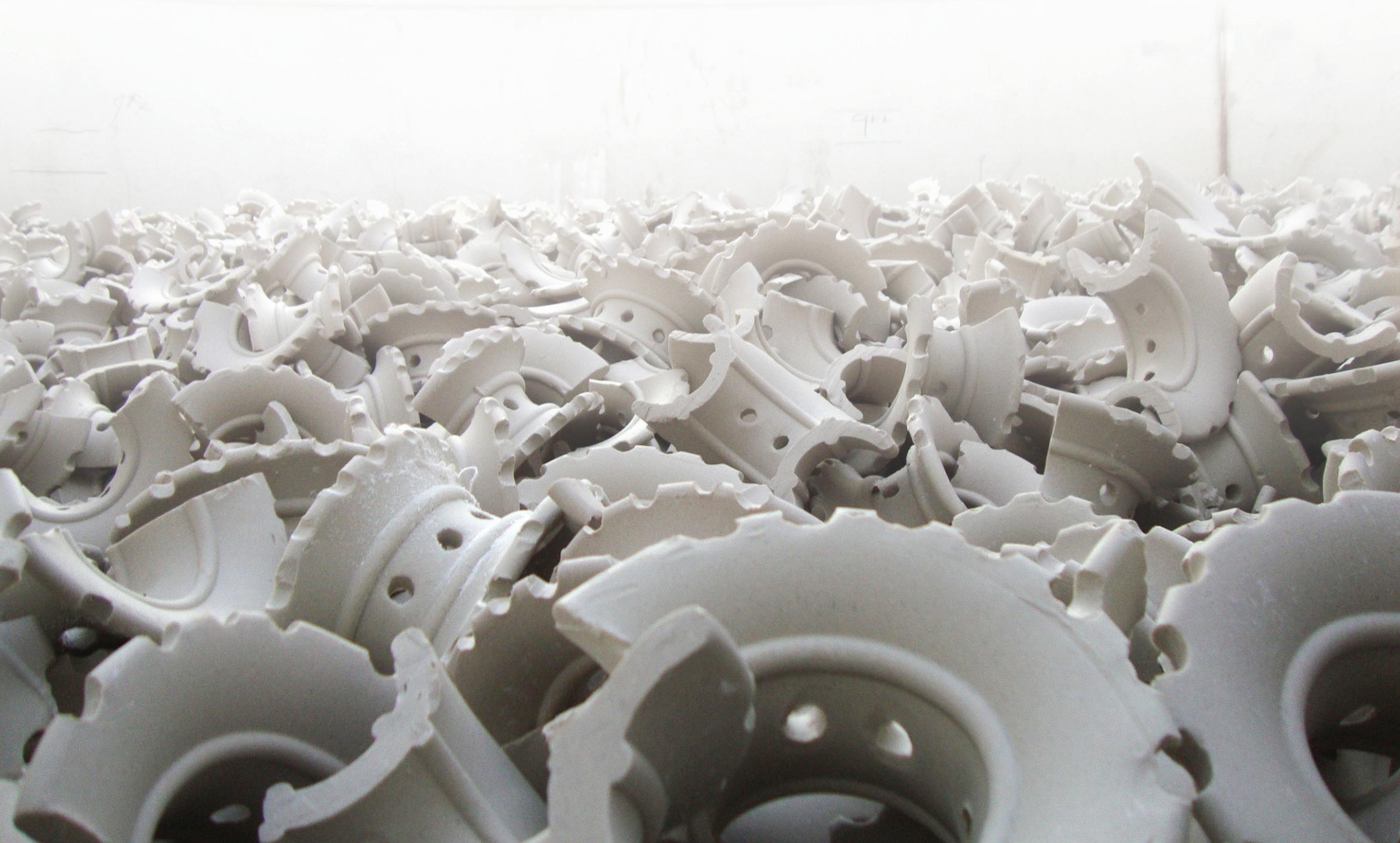
- Ceramic Packing Saddles
- Ceramic Packing Support
- Quartz Rock
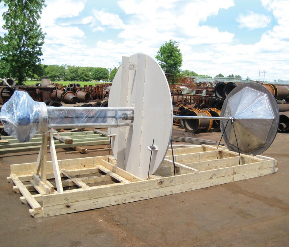
Flow Control
- Engineered Dampers & Valves for S02/S03 Applications
- PTFE/PFA Lined Valves
- 316SS, Alloy 20, 310SS Valves
- MONDI™ Thermowells
- PTFE Spargers
- Orifice Plates
- Pressure & Temperature Gauges

Piping Technology — The world leader in reliable and cost effective products for the sulfuric acid industry since 1991 Acid Piping Technology • 2890 Arnold Tenbrook Road • Arnold, Missouri 63010 USA Telephone: (636) 296-4668 • Fax: (636) 296-1824 • Email: info@acidpiping.com • Website: www.acidpiping.com
Acid
Acquisition in Augusta, Southern States returns to its roots
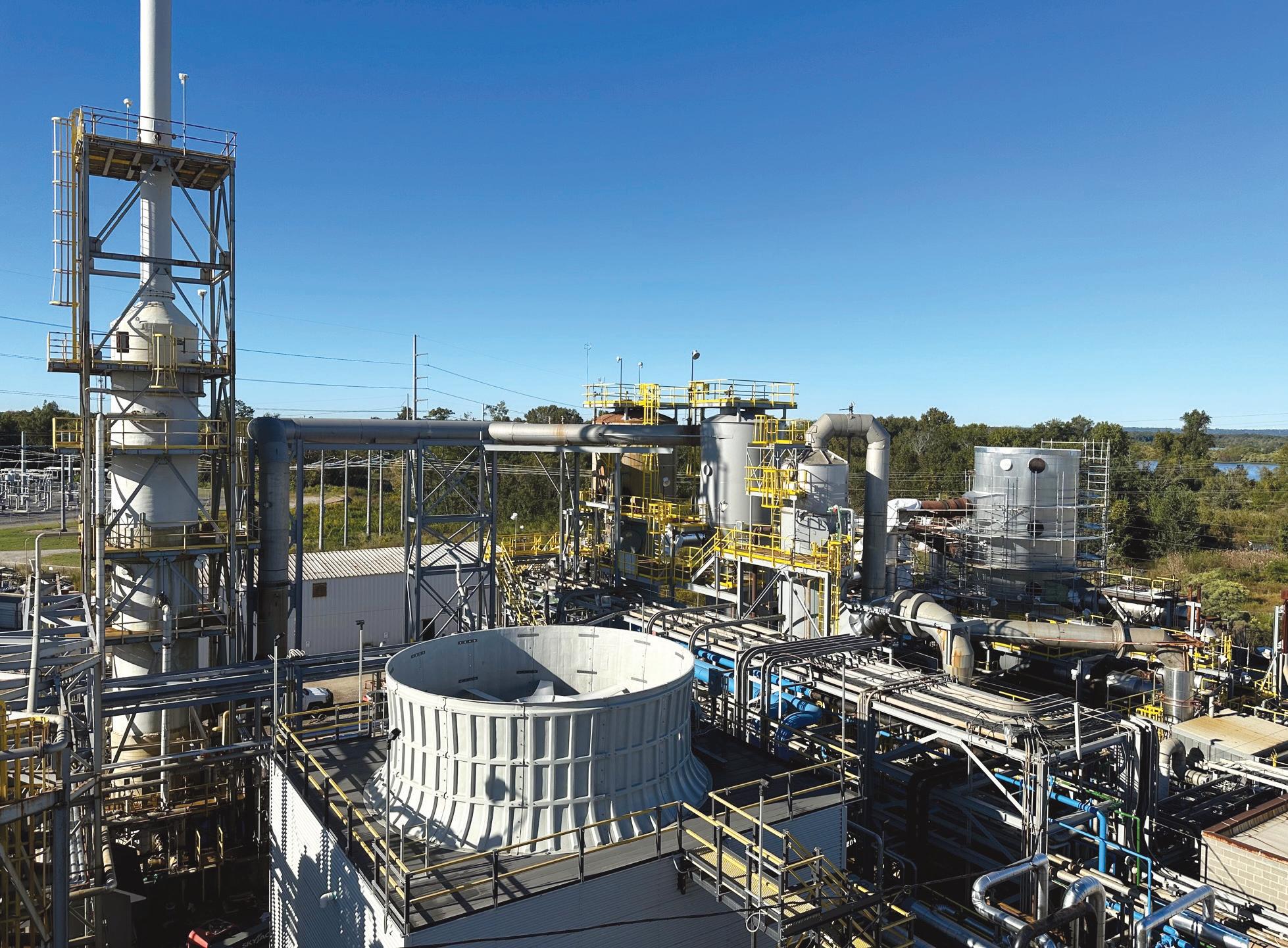
Sulfuric acid producer Southern States Chemical (SSC) recently added a manufacturing facility to its inventory of production sites. With two coastal sites already part of the SSC family, the newest addition, based in Augusta, GA, provides an inland location and thus protection from coastal storms. SSC purchased the idled plant, formerly owned by ChemTrade, in the Spring of 2022. Over the following year and a half, a team of SSC staff and industrial contractors refurbished the facility to meet its new owner’s exacting goals, including enhancing the reliability of acid supply for its customers.
“Augusta is a good location relative to our customer base and is away from the coast which adds further strength to our robust production capabilities,” said Philip Rowland, VP of Operations at SSC. The company’s other acid plants are located in Wilmington, NC and Savannah, GA.
The new location also has historical significance to the family-owned SSC. Augusta was the company’s first home when it started as a fertilizer operation in 1897.
History
Southern States Chemical started as Southern States Phosphate and Fertilizer Company supplying local farmers with fertilizer. In 1902, the company moved from Augusta to Savannah and for sixty years produced sulfuric acid solely for its fertilizer operation. In the mid-1960s, the site’s first sulfuric acid contact plant started production, supplying sulfuric acid to the industrial sector for the first time. A few years later, a second plant started production.
In 2000, the company reorganized and formed Southern States Chemical with Dulany Industries as its parent company. Soon thereafter, Southern States Phosphates and Fertilizer shut down its fertilizer manufacturing operation while SSC carried on producing and marketing sulfuric acid.
In 2001, SSC purchased the Wilmington, NC sulfuric acid facility from KOCH Sulfur Products. That same year, a 16,000-ton capacity import tank was built in Savannah thereby allowing the company to bring in ocean-going vessels. The Savannah operation received its first sulfuric acid import delivery in January 2002, thus giving the company greater flexibility and reliability to meet customer demand.
In 2010, SSC replaced the older Wilmington plant with a new plant: the Wilbara plant. With the addition of Wilbara, marketing increased to 650,000 tons annually further strengthening Southern States’s position as a leading supplier of sulfuric acid on the East Coast.
In 2017 Dulany purchased the SeaPoint Terminal Industrial Complex, which included a mile of deepwater frontage along the Savannah River shipping channel, onsite rail service, as well as a third Savannah-based acid plant, operating at 1,000 TPD.
Now, with the new Augusta facility in the mix, SSC has further strengthened its overall operation. “It gives us three relatively large locations, spread out, each well positioned relative to our customer base. The plants can very efficiently serve their local customers and are able to back each other up as needed which supports our key goal of being the industry’s most effective and reliable supplier,” said Rowland.
Key Compton, President of Southern States Chemical, added “Our team has done an amazing job of repurposing
By: April Smith, Editor
an idled captive burner into a meaningful, additional production and supply point for the southeast industrial marketplace. The Augusta operation not only expands our capabilities within the southeast but, in conjunction with our existing facilities in Savannah and Wilmington, dramatically strengthens and enhances our reliability of supply to the existing customer base.”
SSC has also maintained a strong safety record, earning the CSX Chemical Safety Excellence Award for five consecutive years. Employing about 160 team members company wide, the company has been family owned and operated since its inception over 120 years ago.
SCC produces sulfuric acid that meets the specifications of the food chemical codex, as well as NSF water treatment certifications. Products are available in a variety of strengths including made to order concentrations
from 6-77 percent, as well as standard strengths of 78, 93, 96, and 98 percent.
Remaking Augusta
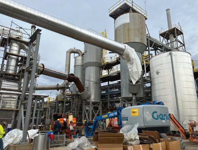
Renovations on the Augusta facility began in May of 2022 and the new plant came online in November of 2023. In between, a team of engineers and contractors inspected the entire facility. Several systems were upgraded including the following:
Overall plant design: The original oleum system was removed and acid capacity modified to 800 TPD.
Storage tanks: All tanks were cleaned, inspected, and
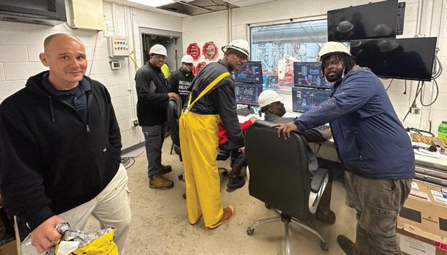
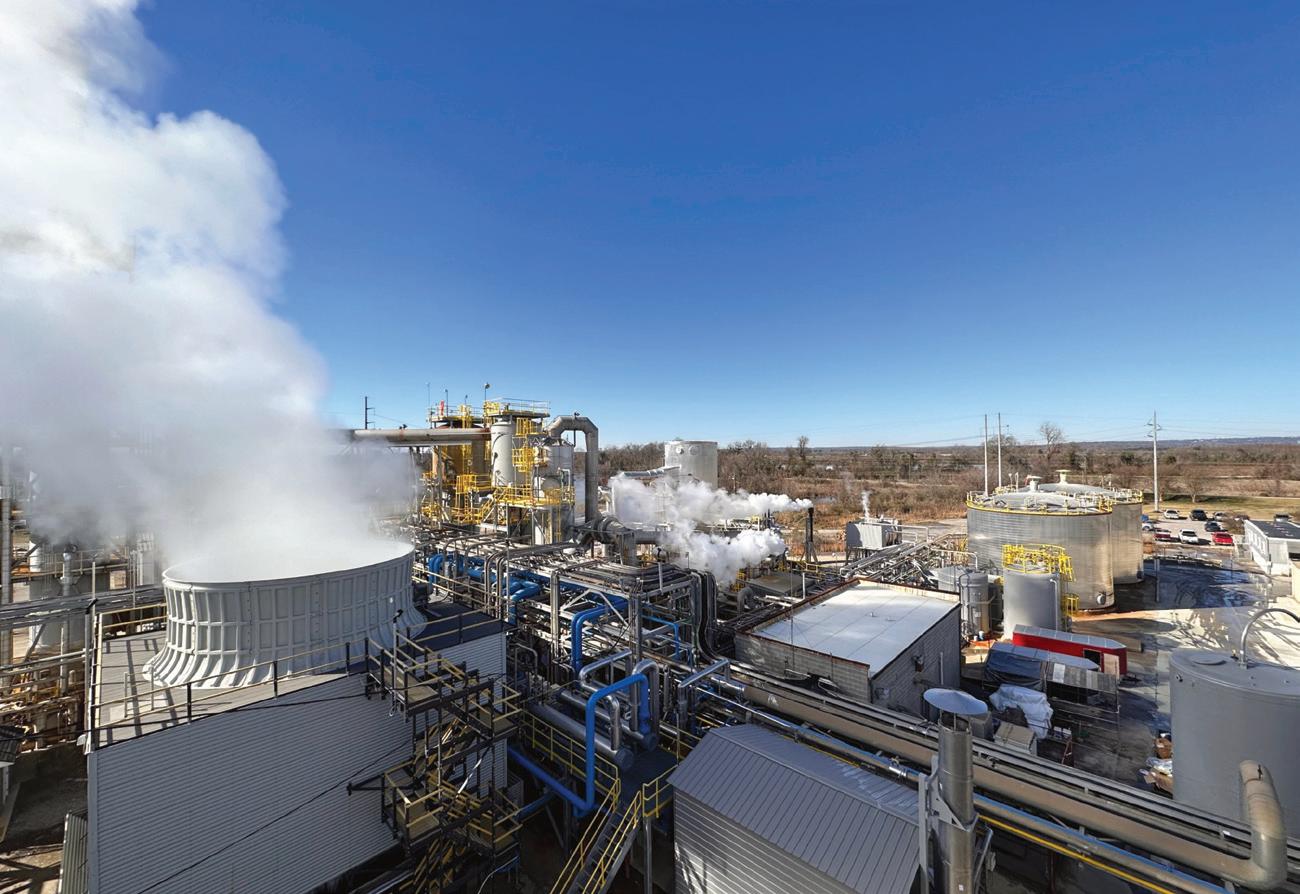
 Operators preparing to start up the new plant.
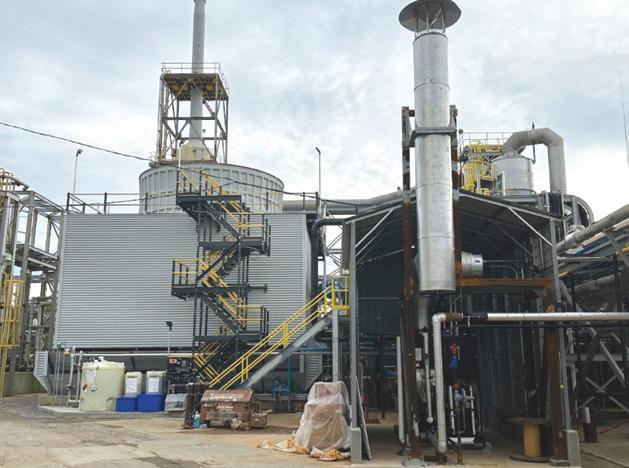
New cooling tower and package boiler.
Sulfuric Acid Today • Spring/Summer 2024 PAGE 7 Cover Story
repaired. Anodic protection was repaired where it existed and added to tanks that lacked it.
Truck loading: Capacity was increased and integrated into a new control system for smoother operation.
Tail gas scrubber: The scrubber was fully inspected and upgraded.
Main control: The control system was completely replaced with a new Emerson Delta V system.
Boiler feedwater: A new boiler system was installed including pumps, deaerators, and water softeners. A new soda ash unloading and storage system was added. The original cooling tower was replaced and a new package boiler added to produce steam when the plant is down.
Acid piping, gas ducts, and heat exchangers: Inspection and repairs were performed throughout these areas and capacity for all acid heat exchangers was increased.
Managing the schedule
One of the main challenges the project team faced involved adhering to a tight schedule. The plan included orchestrating a slew of contractors to complete a variety of tasks, test and validate the individual components, and have the entire system started by the end of 2023.
“We managed this with regular communication and extensive planning,” said Rowland. “We had weekly project meetings and a detailed project schedule by area that we reviewed regularly. Then we focused additional resources in areas where we were running behind schedule.”
Capable contractors experienced with scheduling demands were critical. “We had an outstanding team working on this project. Each member had a different area of the plant, so communication was key in coming together to meet the start-up date,” said Wes Riddell, Engineer, SSC.
Key contractors involved in the project included MECS, Inc., a subsidiary of Elessent Clean Technologies, who assisted with process design.
“We worked with MECS to develop a good plan early on so we could prioritize items we knew would be long lead time items, such as acid coolers, acid pumps, and the entire boiler feedwater system,” explained Rowland.
MECS provided heat and material balances for the new configuration, a modified duct design, and improved SO2 control to the scrubber. All new catalyst was installed including MECS’ specialized Hexa-Lobe 13mm Ring GR330, which was used in the first pass to extend run time between shutdowns to three years. To protect downstream equipment, remove submicron mist, and control emissions, MECS® Brink® mist eliminators were fitted in the absorbing towers along with a ZeCor ® mesh pad in the drying tower.
Other contractors included Acid Engineering & Consulting, who assisted with the scrubber system and Gulf Coast Industrial, who helped with the full plant inspection including internals, hydrostatic testing, and repairs in the acid system. Also helping to complete the work were 360 Industrial, Austin Industrial, Control Southern, Country Way Incorporated, Jisk Electrical, Roberts Company, and SFC Industrial.
“We couldn’t have done this project without the many capable contractors working with us side-by-side” Riddell said.
Within SSC, the project sourced talent from several areas and new jobs were created for continued operation. “The team consisted of engineers from our existing plants,
former ChemTrade employees who previously worked at the plant, and completely new people hired to ultimately operate and maintain the facility,” Rowland said. “Many were completely new to sulfuric acid manufacturing. We sent new operators to our existing plants for training and brought some of our operators to the new plant to help with the start up.” MECS provided the operator training as well as startup services.
Years of disuse
Another hurdle the project team navigated was remaking a facility that had sat idle for six years. Overcoming this challenge meant top to bottom inspection and closely observing plant operations early on.
“Evaluation of the plant was critical and very time consuming,” explained Rowland. “Some original equipment that tested well initially gave us trouble once the plant started running continuously. We had to work through this by carefully monitoring the plant during the early stages. The new control system is a great addition, but it required us to carefully monitor operations during start up to make sure the process was designed and operating properly, from testing interlocks; to monitoring temperatures, pressures, and flows; to monitoring the accuracy of the old and new instrumentation, and tuning control loops,” he said.
Going forward
What does the future hold for SSC Augusta? “We still have many improvement opportunities,” Rowland said. “We are currently venting a portion of our steam, but we intend to install a turbine generator set or turbine drive on our main blower so that we can generate electricity. We also plan to make further improvements to our acid loading system and traffic patterns to continue to improve our loading efficiency.”
For more information, visit www.sschemical.com. q
SBS Scrubber, new cooling tower, and sulfuric acid plant in the background.
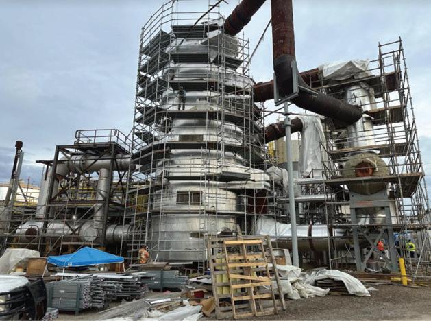
Converter, waste heat boiler, and superheater nearing completion.
Acid towers and soda ash storage tank nearing completion.
PAGE 8 Sulfuric Acid Today • Spring/Summer 2024 Cover Story
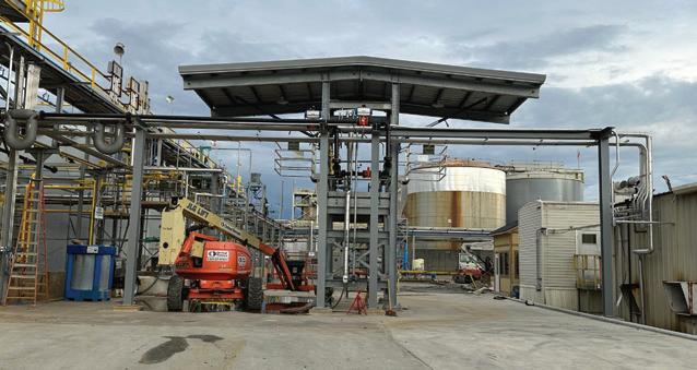
New acid truck loading stations.

VIP Internat I onal 6638 Pecue l ane, Baton r ouge, la 70817 (225) 753-8575 www.vipinc.com Why Gamble with Your Maintenance Dollar?
What lies ahead?
By: Fiona Boyd and Freda Gordon, Directors of Acuity Commodities
In our last article we noted key factors for the sulfuric acid market in 2024 would be: demand from Morocco and Chile, Indonesia’s requirements, market conditions in China and Europe, and freight rates. Below we discuss these factors, as well as others, and the corresponding potential impacts on the sulfuric acid market.
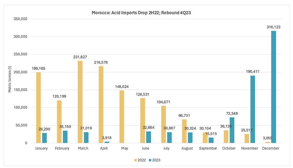
In prior issues, we have discussed how Morocco, which imports to support phosphate fertilizer production, largely retreated from the sulfuric acid import market in the second half of 2022 amid deteriorating conditions in the global fertilizer market. However, fast forward about a year ahead and those downstream market conditions began to improve. As a result, Morocco returned to the acid import market in August 2023 and continued to snap up notable volumes of supply of sulfuric acid, mainly from northwest Europe. The impact was evident with it importing just over 500,000t of sulfuric acid during the last two months of 2023 compared with an average of around 30,000 t/month during the first 10 months of last year.
Entering 2024, Morocco stayed in the market, continuing the buying spree, which squeezed supply availability from the northwest Europe region accordingly. And while last year we noted domestic demand for industrial applications was weaker, which remains, some market uplift has been seen from a tight molten sulfur market in Europe. This has resulted in sulfurbased acid producers seeking incremental smelter acid supply, further reducing availability, but whether this demand is sustainable remains to be seen.
As we look to the balance of 2024, what is critical for the northwest Europe supply market is sustained demand from Morocco and freight rate complexities.
For Morocco, it is important to note its sole importer, phosphate producer OCP, is understood to have only sourced sulfuric acid on a spot and quarterly contract basis. This implies uncertainty moving forward as to how much demand Morocco will have. If it reverses course and retreats from importing as it did in 2022, this suggests length from northwest Europe would emerge.
At the same time, suppliers are grappling with freight issues as the drought in


the Panama Canal effectively cuts off some markets, such as Chile, due to the impact on voyage time and freight rates for seeking alternative routes. While routes to other key outlets such as the US and Brazil are not compromised, we are seeing weaker import demand in Brazil, an all-spot market. For the US, it is a price sensitive market hinging largely on domestic merchant sulfuric acid market conditions.
With no notable improvement expected with the Panama Canal situation in the coming months, demand from Morocco will have to be sustained to keep product effectively flowing.
Turning to Chile, which is supply dependent on Peru and Asia, at the time of writing we are seeing limited spot import demand there. This is largely because import buyers worked to secure their first quarter consumption volumes as this is the peak of swell activity which can and is disrupting port operations, and therefore the ability for vessels to unload product. While we do expect spot demand in Chile to pick up going into the second quarter, we expect sufficient supply availability from Peru and Asia to meet this demand. Our expectation of demand emerging there is in part due to the pending closure of a domestic smelter in Chile – Enami’s Paipote – by April. This will leave some small to medium acid consumers in inland Chile uncovered, which would support imports to cover this consumption. In addition, some regular import buyers in Chile leave some of their annual consumption needs open for the spot market, which should provide some market support. Domestic supply disruptions, out-
side of Paipote, are an additional factor that could stimulate import demand.
Meanwhile, our expectations of sufficient supply availability from Asia are driven by market conditions we have seen this year thus far, which is highlighting regional variances. As an indication, our spot export price for Japan/South Korea around mid-February was $1-9/t FOB compared with northwest Europe assessed as $4550/t FOB.
With lack of spot demand in Chile, Asian suppliers are more dependent on other markets, such as within southeast Asia. This includes Indonesia where demand has been lower than expected at the start of 2024. There are a few reasons likely contributing to constrained import demand in Indonesia including a weaker nickel market. Nickel prices began to decline around mid-January due to oversupply. Around the same time, some nickel projects in Indonesia were cancelled with shrinking economic value and uncertain market conditions cited as drivers.
Amid the weaker nickel market conditions, Indonesia acid consumers that can also burn sulfur to cover their own consumption are thought to be prioritizing that due to economics. For example, Acuity’s Indonesia spot sulfur import assessment at the time of writing was $95-100/t CFR, equivalent to around $32-33/t acid cost if we assume one tonne of sulfur produces around three tonnes of sulfuric acid. This compares to our spot acid import assessment of $40-45/t CFR.
In addition to demand concerns for supply from Asia, the market is bracing for
new base metal smelter capacity that will add new supply to the merchant acid market. New smelters are expected to start up in India and Indonesia around mid-2024, for example.
There is some uncertainty around China’s supply as top copper smelters there have called for production cuts due to tightening copper concentrate supply which is impacting economics accordingly. There is no consensus among acid players what (or if any) measures will be taken, while many are skeptical of the impact because even if China pulls back, the under-supplied concentrates will likely move to other markets. Ahead of the Lunar New Year, with many Chinese off between February 10-17, producers in China were focused on the domestic market and reducing inventories, clouding the outlook for expectations following the holiday period. We have discussed in previous issues that China’s influence is topical because of its unpredictability. This is in part as producers weigh the netback of domestic versus export sales. In the past couple of years, Chinese smelters tend to export more when FOB values are higher.
In addition to all the above, there is a list of macro factors that Acuity will be monitoring as 2024 progresses, including economic growth in key acid import and export markets and the speed of green energy transition that appears to be slower than anticipated in some regions. It will also be a busy election year, meaning possible new policies will impact economies, agriculture, and mining. Wars and conflicts are on our agenda, too.
Acuity Commodities provides insight into the sulfur and sulfuric acid markets through price assessments, data, and supporting analysis. Offerings include weekly reports on the global sulfur and sulfuric acid markets. For North America, Acuity offers a bi-weekly report on sulfur and sulfuric acid as well as a monthly report on industrial chemicals, including caustic soda and hydrochloric. Acuity also has developed a database detailing battery and mining projects under development in North America that could consume products such as sulfuric acid. In addition, Acuity does bespoke consulting work. Please visit www.acuitycommodities.com for detailed information. q
Freda Gordon, Acuity Commodities
Fiona Boyd, Acuity Commodities
MARKET OUTLOOK PAGE 10 Sulfuric Acid Today • Spring/Summer 2024 Feature
Better integrated, more efficient and cleaner production of CO2-free phosphate fertilizers LEARN MORE chemetics.info@worley.com chemetics.equipment@worley.com Leveraging oxygen from water electrolysis / ammonia production, CORE-SO2™ technology decreases acid plants’ environmental footprint and greenhouse gas emissions while recovering clean energy and enhancing plant profitability. WORLEY.COM/CHEMETICS Reduce stack emissions Decrease CAPEX Lowest cost construction Produce CO2free power Use of green ammonia/ hydrogen O2 CORE-SO2™ sulphuric acid technology UNLOCK YOUR GOALS WITH IT’S THE SAME, BUT BETTER
No fossil fuels required
98% lower emissions
60% less plot space
55% fewer contruction materials
50% decrease in CAPEX
•
•
•
•
•

Getting site-specific: a look at the contractor pre-qualification process
By: Patrick Ferguson, CSP, Technical Project Manager, VIP International
In our last article we explored the past three decades of safety and how it has evolved from being an afterthought to the forefront of our workplace. Many aspects of safety in the sulfuric acid industry improved regarding training requirements and how training is delivered. As regulations evolved, so did training offerings and methods of delivery. Many companies were required to develop their own training programs or have them developed by third party companies. With so many new requirements, it was now up to the companies to ensure that their employees were trained in accordance with regulatory requirements but also with the policies and procedures set forth by their organizations. But, what about contractor companies and those outside of the owner organizations? Aside from the onsite orientations and third-party training, how were owner sites able to manage contractor companies to ensure that their policies and procedures, EHS records, EHS programs and training met the same standards?
Many companies began to develop prequalification processes as a means of ensuring that contractor companies performing work within their facilities were following requirements set forth by government regulations and company policies. There were many considerations when developing these processes.
What information would be requested of the contractor company? Who would manage the information? How would the information be evaluated and measured? If there were deficiencies in the information provided, what were the thresholds that would prevent a contractor company from being qualified? If denied qualification, what recourse did the contractor company have to be considered again?
To facilitate data collection, written prequalification questionnaires were developed by site owners and delivered to contractor companies to populate and return for evaluation. The questionnaires contained requests for basic company information such as office addresses, company contact information, company executive information, services performed, company history and other administrative data. They also contained requests for historical contractor company information based on government reporting requirements such as injury and illness data, insurance data, and Safety Data Sheet management data.
To organize, manage, and evaluate the data provided by contractor companies, siteowners used resources within their company such as EHS administrators and personnel who understand government requirements and company policies regarding these subjects. Many times, companies were commu-
nicating directly with the contractor personnel they would be working with on-site, which allowed clear communication of expectations and a direct line when discrepancies were discovered. Site owners would even perform periodic audits at the contractor’s headquarters where training, quality control, safety-sensitive equipment inspections, and recertifications occur. They would also interview contractor employees to confirm their knowledge of safety specific to the work performed. This provided the site owner with valuable insight into the safety culture within the contract company.
Many companies, particularly larger organizations with multiple sites, quickly realized that management of their pre-qualification program was a daunting task requiring large resources and budgets to maintain. To fill the void, third-party auditing firms began to establish themselves as an alternative to brick and mortar programs within site-owner organizations. These firms offered to manage the contractor company pre-qualification process and ensure that questionnaires stayed up to date with ever changing regulations and company policies. This proved to be the solution for many larger companies as they began to switch to third-party auditing firms and rely fully on them to determine which contractor companies were qualified to perform work at their sites.
The third-party auditing model streamlined the pre-qualification process by creating websites that store all questionnaire information provided by the contractor companies. Contractor companies were now required to pay annual memberships to have the thirdparty auditing firms collect their data, evaluate it based on owner site standards, and give compliance ratings that would deny or allow contractor company services within the owner site. This service provides an additional option for contractor companies to access their data and historical information outside of the internal systems. It also allows a site owner company easy access to information they may need to review regarding a new contractor company potentially working at their site. One limitation of using these systems is that direct communication between site owner companies and contractor companies now became more difficult when discrepancies arise regarding the data. Another limitation is that site audits are no longer performed removing the face-toface look into the culture within the contractor organization.
The third-party auditing systems have expanded greatly from their original function. EHS manuals are examined using specific questions relating to the contractor’s type of work. Site-specific training can now be conducted directly through the websites without attending an on-site class. Contractor training data management software has been integrated giving users the ability to track their personnel’s training expirations at each site. Contractor policies relating to transportation,
sustainability, international data statistics, and even cyber security are now examined to paint a comprehensive picture of the contractor companies. These systems have evolved into a one size fits all approach no matter the size of the contractor company. This one size fits all matrix can be difficult for specialty contractors who do not fit in the matrix. A specialty contractor may only perform a specific type of service that would not normally require many of the components of the matrix. The contractor must appeal directly to the site management for a variance to the matrix.
As more and more site owner companies switch to the third-party auditing model for contractor pre-qualification, competition in the market has risen. There are multiple firms offering these services and many independent companies offering to manage contractor company data within the systems. This can become overwhelming and create confusion for both site-owners and contractor companies alike. It is important that both owner sites and contractor companies keep a direct line of communication regarding any potential issues relating to the use of third-party auditing systems. Manhours required by the contractor to maintain this system can be daunting. During the annual renewal the third-party company may edit or change the existing audit requirements of the contractor for each plant site represented. To comply with these changes effectively and efficiently, a dedicated person, experienced with these audit systems, should be assigned the task of overseeing the annual renewal and maintenance of the system. There are many factors for site owners to consider when choosing which system to implement for their organization. The system should be user friendly and easily accessible for both contractor and site owner organizations. The type of work the contractor company performs and the size of the company should be considered when establishing grading or compliance ratings. The types of online training offered through the system should be scrutinized to ensure they meet not only the policies of the owner site, but also any regulations that might apply to that site. Every additional feature offered by the firm should be assessed for its overall value in what the site owner organization is trying to accomplish.
Pre-qualification remains an important aspect of the partnership between owner sites and contractor companies. In the everchanging workplace, third-party auditing systems are a feasible option to ensure that contractor companies align with the policies and safety performance that is expected at the owner site. There are still limitations to these systems that require direct communication between contractors and site owners. With thorough planning and consideration, a pre-qualification process can be another tool in the toolbox that enhances safety for everyone in the workplace.
For more information, please visit www.vipinc.com. q
SAFETY SECTOR PAGE 12 Sulfuric Acid Today • Spring/Summer 2024 Department
BASF has you covered!
Experience the next level in pressure drop reduction with BASFs new X3D™ Sulfuric Acid catalyst series based on 3D printing. A pressure drop reduction of up to 75% in comparison to Star Ring catalysts can
Simulated pressure drop
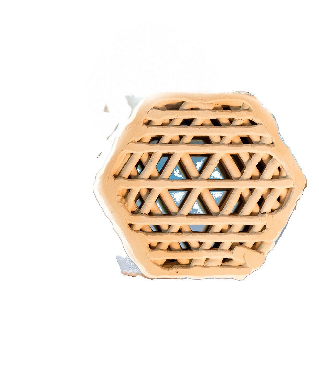
Benefits of the X3D™ Sulfuric Acid catalyst
Higher conversion
Lower energy consumption
Decreased SO2 emissions

catalysts.basf.com/sulfuric-acid
Pressure drop per meter [Pa/m] Empty pipe velocity (air @ 20 °C) [m/s] Star Ring Shape X3D Shape 14000 12000 10000 0,00 0,25 0,50 0,75 1,00 1,25 1,50 1,75 2,00 2,25 2,50
In Search for Ways to Reduce Your Energy Consumption?
LESSONS LEARNED: Case histories from the sulfuric acid industry
Reconciling catalyst performance with converter section condition
By: Walter Weiss, Process Engineering Consultant, Elessent Clean Technologes
Effectively all sulfuric acid plants, regardless of type, monitor the stack gas for SO2 content. The focus is not just to minimize yield loss, but the SO2 emissions to the environment are limited by regulation. SO2 oxidation occurs in a multibed catalytic converter with interbed cooling. The beds are normally stacked vertically in a single vessel with ducting in and out of each catalyst pass connecting to the cooling / heating equipment supporting its temperature control.
This focus on controlling conversion leads plant owners to monitor the condition of the catalyst performance by various means and make decisions on the need for catalyst bed change out in full or part. This can lead to a substantial investment and a decision that may not be taken lightly. There are various means that can be used in making this decision.
1) Monitoring observed temperature rise pass by catalyst bed pass over time. Sulfur burning plants often rely on this to decide when to schedule catalyst replacement. This is more difficult in spent acid regeneration plants and metallurgical plants where gas conditions and plant rate can change on a daily or even hourly basis. With these changes may come changes in converter bed temperature profile–making this a moving target.
2) Catalyst suppliers can assist with a computational simulation based on collected field data including gas strength, plant rate, and catalyst bed temperatures. This can assist to clarify some of the variation noted in temperature rise data. Results of the simulation are no better than the field data that goes into it. Field data is not always consistent, so some room for interpretation is required.
3) Sampling data using a portable gas chromatograph provides an improvement for understanding field data. This uses the same computation simulation software noted above but with improved certainty in the gas compositions. Moreover, this procedure allows for checking some of the heat exchangers for leakage and even quantifying the leakage rate.
Shortcomings on converter performance can be and often is due to catalyst damage or age. Damage may result from exposure to acid or water spray, fluorides, arsenic, or unusually heavy coating of solids such as ash or metal scale. Damaged or aged catalyst beds can be replaced in full or refreshed by screening the bed to remove ash and dust while making up
screening losses (nominally twenty percent) with fresh catalyst.
However, sometimes decisions are made to replace catalyst which does not provide the improvement expected. The tendency to blame the catalyst quality may be misguided. Mechanical deficiencies may be causing loss of converter performance and increased yield loss. These could be due to failure of components over time. If poor performance is observed from the start, it may be due to poor design features. These deficiencies may mask themselves in overall loss of bed performance. This is difficult to separate from catalyst condition and performance by the normal means expressed above. A deeper look through shutdown inspections as well as hydraulic design conditions may be warranted.
Design features influencing performance
Catalyst designers assume uniformity of the gas velocity, composition, and temperature when it enters the catalyst bed. For many plants, gas concentration is determined well upstream of the converter. Desired mixing effectiveness within a couple tenths of a percent SO2 prior to the catalyst is expected.
Temperature uniformity is more of a problem for most catalyst passes. Ideally, any temperature variation across the top of the catalyst bed should be no more than 2 or 3 degrees Celsius. In practice, this has been observed to be considerably greater. Upstream equipment with bypass ducts and valves will need one or two elbows prior to the converter to provide mixing. Hot gas and cold gas temperatures may be several to many hundreds of degrees apart. For pass one, the hot gas from a sulfur burner furnace may be 1,100 degrees C and cold gas after the boiler may be 350 degrees C. Improperly mixed gas can leave the gas cross section reaching the converter with any temperature between these two bookends. An inline mixer could be considered. Absent this, elbows in the ducting are the best solution. Pass 2 inlet may have two converter nozzle entries from parallel steaming and gas heat exchange equipment. There is no opportunity to mix in the ducting due to layout. Controls are often provided in the design to maintain the same or similar gas temperatures coming from both pieces of equipment. These controls may be ineffec-
tive, and operators may struggle to maintain this within acceptable bounds.
The most difficult condition of nonuniformity to measure and control is gas velocity. This can be difficult to visualize without the assistance of CFD modeling. Gas flow normally enters a converter vessel through side mounted nozzles. Gas velocity in the duct and nozzle are much higher than velocity through the converter bed. Duct and nozzle velocity are radial in flow orientation and catalyst bed velocity is axial. Deceleration of this gas is accomplished stepwise–starting in the nozzles and finishing in the vertical volume above the catalyst. Failure to accomplish this properly can result in holes and depressions blown into the catalyst surface layer. The ceramic hold-down material must

be adequate in size and depth to protect against this. Higher than design velocity may begin to displace the ceramics. Worst case, significantly higher than desired gas velocity can damage the catalyst rings. This is more likely to occur below a heat up duct nozzle which often does not get the same level of engineering. See Fig. 1.
It is common practice to flare the main gas nozzle and reduce the gas velocity. Deflector vanes inside the nozzle increase the effectiveness of this deceleration and distribute the gas flow around the converter cross section more equitably. The basis of this design is the Bernoulli equation in terms of pressure and velocity head of the gas:
V2 /2gc
Engineering guidelines for the converter design are in place to determine
these optimum values in the duct, in the nozzle, and in the converter cross section. This incoming gas velocity head needs to be offset by a minimum bed pressure drop. A catalyst supplier and designer of converters can assist in evaluating these hydraulic conditions for your specific facility.
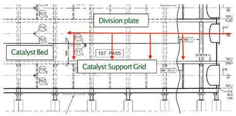
Adequate volume between the top of the catalyst bed and the bottom of the division plate above is also needed to allow deceleration of the gas and move from a horizontal flow plane to a vertical flow plane. The objective is to get a constant downward velocity over the catalyst cross section. See Fig. 2.
With proper uniformity of gas conditions atop the converter pass, one can expect uniform conditions at the outlet of the bed. Gas sample analyses / temperatures should be representative of the catalyst bed as a whole, wherever measured.
With non-uniform gas conditions atop the converter pass, then one can reasonably expect non-uniform conditions at the outlet of the bed. Gas sample analyses / temperatures will vary with location. Mixing in the outlet duct and downstream equipment will show a changing set of conditions. This may be evaluated by any of the methodologies noted above as a loss of catalyst performance but reflect mechanical shortcomings not to be remedied with new catalyst.
The use of the radial flow or blooper plate converters challenges the hydraulic design norms referenced above and needs to be reconsidered in the context of the presence of the core tube. A core tube with internal heat exchanger provides added hydraulic considerations for gas flow into and out of the core tube to access an internal gas heat exchanger or two.
Inlet gas velocity head, as discussed above, needs to consider the core tube as part of the gas deceleration. Evaluation of existing converters and those in the design phase globally shows some consistencies. Inlet gas velocity bounces off the core tube and concentrates toward the shell wall at
Fig. 1: Catalyst bed depression resulting from high localized gas velocity.
Fig. 2: Converter bed elevation profile gas flow orientation.
PAGE 14 Sulfuric Acid Today • Spring/Summer 2024 Feature
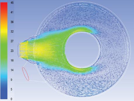
roughly 90 and 270 degrees from the inlet. Little flow is observed 180 degrees from the inlet while in the shadow of the core tube. Before adequately decelerating, the gas enters the top of the catalyst bed. See Fig. 3.
Case Study: One plant encountered a nearly 40 degrees C temperature drop and a decrease in measured conversion of more than 10% between the instrumentation/sample valves located on the converter shell across from the gas inlet nozzle versus the duct instrumentation/ sample valves located at the superheater inlet downstream. If uniform conditions existed, this data would be the same.
The Hot Interpass Heat Exchanger and sometimes the Hot Heat Exchanger may be located inside the core tube. This design saves on capital cost and reduces pressure drop, external gas leaks and layout space. However, this also expands the converter diameter and complicates inspection and maintenance on the heat exchangers. It makes exchanger leaks more difficult to detect while in operation. And it makes temperature control more difficult–as the bypass gas normally is connected externally from duct to duct or from duct to heat exchanger vestibule.
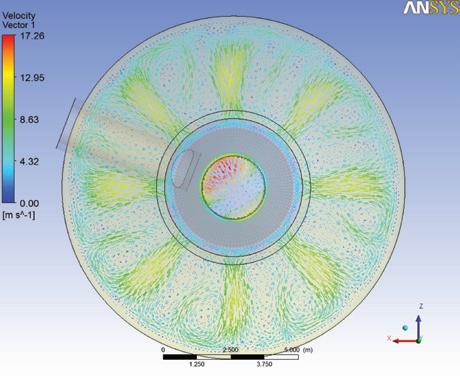
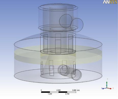
To access the internal heat exchanger, gas enters and exits the core through openings in the core tube. This is depicted in Fig. 4.
Openings from the core tube onto the converter pass need to be considered in terms of open area and location. Sometimes this consideration is better than others. Figure 5 shows this gas velocity dis-
tribution with an uneven velocity profile of more than 2:1.
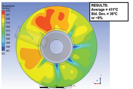
Inadequate attention to mixing of the cold bypass gas into the core tube can result in wide variations of gas temperature leaving the heat exchanger. Fig. 6 shows the temperature profile. Temperature variation is noted to be well above accepted values. Most of the catalyst bed as shown will be ineffective.
Operating / maintenance issues influencing performance
Once designed and operated, the converter system may develop operating issues not observed during start up. Normally interpreted as aged or damaged catalyst, the list below suggests scenarios that can contribute to an increase in SO2 emissions even with good catalyst conditions.
• Gas heat exchanger leaks often bypass one or more catalyst passes. A Cold Heat Exchanger located after the Main Compressor on the cold gas side and prior to the Final Absorbing Tower on the hot gas side can leak 11 to 12 volume percent raw SO2 process gas into 100 ppmv stack gas. A one percent gas leak results in more than an order of magnitude increase in stack emissions. This will not be observed by converter bed temperature rise analysis or even a computer simulation. Comparable leaks in other heat exchangers will have less of an impact on stack emissions and will leave a footprint of unexplained temperature rise in lower passes.
• Division plate leaks in a carbon
steel grid and post converter would impact temperatures but not gas composition. A replacement stainless steel converter with the same pass order would be no different. Modern stainless steel converters can arrange pass order based on optimum duct layout and maintenance access requirements. Internal leaks can impact gas compositions from pass to pass. And with the radial flow converter design, there are many additional potential leakage points other than division plates associated with the internal heat exchangers. These can be difficult to detect by calculation or analysis. Hence the reliance on visual inspection.
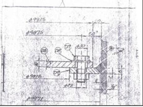
Fig. 7 shows a bolted division plate design (not welded) that allowed gas bypass in some or all of three converter division plates. After some operation, the bolting and washers loosened up. The leakage rate was adequate to more than double the

Bulkofradiant trappedinfrontzone
Hotterhere
stack SO2 emissions. Repairs done by welding a channel around the shell attachment brought emissions in line with design.
• Also leading to gas bypassing problems is thermal expansion. Converter temperatures may reach or exceed 620 degrees C. Stainless steel materials on a large converter diameter may lead to radial growth of 5-7 cm. This will lead to expansion of the shell and the internals. Fresh catalyst will move as a result of the expanding shell, with catalyst filling the void up to an angle of repose. This angle will vary with catalyst type. At the most, an angle of 60 to 65 degrees might be expected. This leaves a gap along the shell wall of 13 cm for a radial movement of 7 cm. In some plants, adding catalyst along the shell wall to adjust for some of this movement and resulting gas bypassing has been done.
There are numerous means to observe poor catalyst performance, but a broader perspective might be an observation of poor catalyst bed performance. These are not the same, as one can see that design decisions or failed mechanical features may appear as poorly performing catalyst. Changing out the catalyst may not bring satisfaction.
For more information, please contact Walter Weiss (walter.weiss@elessentct.com) of Elessent Clean Technologies or visit the company’s website at ElessentCT.com. q
Tightresidence timedistribution Coolerhere Spiralcreatesmuchlonger “contactpathway”,oroverall distancein closecontact toreact, evenwith lower temperatureshere

Solidperimeterforbackmixing -same aschoke ring
Whatdoesthismean forSRUOperators?
Increasedvelocityand temperaturecarriedto tubesheet
Broadresidencetime distribution meansinsufficient RTforsome ofthereactions
③ More complete Ammonia Destruction/ increasedcapacityto process NH3ifdesired
③ Better BTEX Destruction
③ Better protection for tubesheet refractory/ coolertemperatures going intoWHB
③ More efficient use offurnace volume means increasedcapacity
③ Better mixing and longer distance together mean morecomplete reactions
③ Lower energy costs when co-firing or in tail gas incinerators
To learnmoreabout theBlaschVectorWallTM anditsbenefits, contactTimConnors, Senior MarketManager-Energy&Chemicals at tconnors@blaschceramics.comorbyphone at 518-436-1263ext105. VisitUsatSulphur
Whatdoesthismeanforsulfur burning acid plants?
③ Nomore fireflies at furnace exit ③ Increased capacity
③ Lower Pressure dropcompared tobaffles
Fig. 4: Schematic of a shell and tube hot gas heat exchanger within a core tube.
Fig. 5: CFD model of gas flow from the core tube to the catalyst pass.
Fig. 6: CFD model of temperature distribution downstream of an internal heat exchanger.
Fig. 7: Engineering drawing of bolted division plate.
Fig. 3: CFD model of gas flow around a core tube. Gas velocities are shown in meters/ second.
580Broadway | Albany,NY12204| 518-436-1263|www.blaschceramics.com
Conference: Stand29 Sulfuric Acid Today • Spring/Summer 2024 PAGE 15 Feature
SensoTech offers inline acid concentration sensor
In the chemical industry, acid concentration measurements have played a crucial role in a variety of areas and applications. These measurements are of great importance for quality assurance and process control in various industries such as the production of fertilizers, the petrochemical industry, the pharmaceutical industry, the food industry, water treatment and environmental protection, and battery production, as well as metallurgy and ore processing.
As important components in numerous production processes, acids must be tested regularly to ensure their efficiency and quality. Various methods can be used to test or improve specific properties.
Acid concentration measurement plays an important role in various manufacturing processes. Pipelines, in particular, represent a critical point as an excessively high concentration of acids can damage the pipes and lead to leaks. In addition, undesirable chemical reactions can be triggered that affect both the quality of the end product and the safety of employees.
For this reason, regular monitoring of acid concentration through precise measurements in real time is essential. Various measurement methods, such as pH measurement or ion-selective measurement (ISE), are used for this purpose. The concentration measurement is not only carried out in pipelines, but also at other critical points in the process, such as in tanks or reactors.
SensoTech’s LiquiSonic® measuring systems enable
inline concentration measurements of acids. The measuring technology is able to analyze the components of substance mixtures and can provide information about the concentration or density in real time. The sensors are based on the principle of ultrasonic velocity measurement. They are therefore virtually maintenance-free and can reliably provide measured values even under demanding measurement conditions.
To determine the speed of sound, a sound pulse is sent through the liquid and the time it takes for the pulse to reach the receiver is measured. Since the distance between the ultrasonic transmitter and receiver is constant by design, the speed of sound can be calculated.
LiquiSonic® sensors can be installed directly in the user’s system without a bypass, which is helpful in appli-
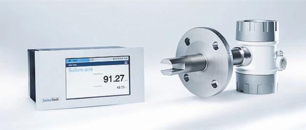
cations such as pipelines. There are also different variants that are tailored to specific areas of application and have special properties.
With the high sensitivity of sonic velocity to sulfuric acid concentration, the LiquiSonic® sensors can achieve an unmatched accuracy of ± 0.03 wt%. LiquiSonic® overcomes the dual sensitivities of both conductivity and density by generating a clear signal in the concentration range of 80 - 100 wt% H 2SO 4 to offer reliable, real-time process data. In the event of acid degradation to a highly corrosive level under 95 wt%, LiquiSonic® detects that critical acid “runaway” to curb the probability of heatexchanger or other component damage, enhancing process safety and control.
The inline LiquiSonic® analyzer reduces manual laboratory measurements, saving labor and material costs in a typical laboratory titration budget for sulfuric acid measurement:
• Sampling time: 15 minutes
• Sampling frequency: 6 times per day
• Investment payback: within 13 months
Overall, acid concentration measurements are essential to ensure product quality, process efficiency and environmental safety in a wide range of applications and industries.
For more information, please visit www.sensotech.com. q
Radiography of full penetration welds in flex hose for safety and reliability
By: Steven Mingis, President & Co-Founder and John Czerwinski, Key Accounts Manager, Branham Industrial LLC
One-hundred percent radiographic inspection of the weldment is a crucial requirement for ensuring the quality, reliability, and safety of welded joints in the production of flex hoses for chemical transfer applications. Radiographic inspection, specifically employing techniques like X-rays or gamma rays, provides a non-destructive means of insuring mechanical integrity and absence of defects for long term performance. Dye penetrant examination and subsequent hydrostatic and/or pneumatic pressure testing are each valuable procedures for detecting any leak, but they can provide evidence of “leak free” only at the time of the test.
Conversely, 100 percent radiography provides physical evidence of any defects, imperfections such as voids, porosity, cracks, incomplete fusion, and lack of penetration within the weld zone. Identifying these issues early on is essential to prevent the compromise of structural integrity, which is particularly critical in applications where safety is paramount, such as
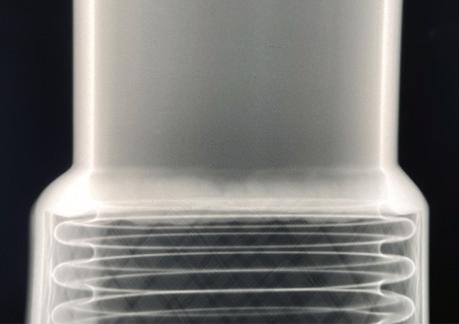

in the construction of flex hoses for highly hazardous, highly toxic, or high temperature process applications. By thoroughly examining the entire circumferential weldment, this procedure ensures compliance to ASME Section IX. This is particularly significant when recognizing the criticality of joining a schedule 80 pipe fitting to a corrugated tube hose with a wall thickness of 0.016”, when even minor flaws can lead to premature catastrophic failures.
Radiography provides the end user a
level of confidence in the structural soundness of these welds, reducing the risk of unexpected failures and subsequent operational disruptions. Safety considerations are at the forefront of the importance of inspecting welds. Flaws within welded joints can lead to leaks, structural failures, or other hazardous situations. Radiographic inspection acts as a preventive measure, identifying potential issues before they escalate into serious problems. This is crucial in industries dealing with volatile sub -
stances, high pressures, or other conditions where the failure of a welded joint could have severe consequences.
Reading and evaluating the film from the 100% radiography is the responsibility of the Level III Certified Weld Inspector (CWI) at Hartford, which Branham utilizes as an objective 3rd party contractor. To the untrained eye, the two images shown here might not appear all that much different.
In conclusion, the importance of inspecting pipe welds using 100 percent radiography cannot be overstated. This method ensures the quality, reliability, and safety of welded joints by detecting internal defects, contributing to the overall integrity of structures, and preventing potential hazards. It stands as a fundamental practice in industries where the reliability of welded connections is paramount.
Branham Industrial LLC is an LGG Industrial Company. For more information email jczerwinski@branhamcorp.com or visit www.branhamcorp.com. q
PRODUCT NEWS PAGE 16 Sulfuric Acid Today • Spring/Summer 2024 Department
The LiquiSonic ® sensors can achieve an unmatched accuracy of ± 0.03 wt%.
Weld (left) exhibits full fusion—acceptable. Weld (right) exhibits incomplete fusion— unacceptable.


Fabrication: Brad Varnum bvarnum@cmw.cc 813-650-2271 Field Services: Ian Legg ilegg@cmw.com 813-365-2085 For more info go to: www.cmw.cc IT ALL BOILS DOWN TO ASME - S and U STAMP Authorized Manufacturer ®

The importance of pump maintenance
By: Ravinder “Ricky” Jaswal, Regional Account Manager, Weir Minerals Lewis Pumps
Maintenance is one of the key components of any successful operation, whether it is a sulfuric acid plant, a manufacturing company, or even your personal auto. In today’s economic climate, with each of us asked to do more with fewer resources, a quality maintenance program has never been more important.
For our purposes, maintenance can be broken down into four basic categories: emergency, routine, preventative, and predictive. Each of these serve a purpose and each take a different toll on our resources. Let’s look at each category in a little more depth.
The first is emergency maintenance. This situation occurs when you have a catastrophic failure of your equipment—for example, the shaft on your pump breaks or you have a tire blowout on the highway. This is the most costly of the four categories because you can’t plan for it. When it happens, you could face overtime labor charges, expedited parts charges, and most importantly, costly unplanned downtime. In some cases, these failures can’t be avoided, but the second maintenance category— routine maintenance—can eliminate some emergency situations.
In the routine maintenance program, we set a maintenance schedule, usually based on past performance of the equipment. At predetermined intervals we remove the equipment from service, inspect it, and repair as needed. A well-developed routine maintenance program can eliminate most of the emergency outages by ensuring that the equipment is always serviced and ready to perform as required. The downside to a routine maintenance program is that it can be a costly operation as you must have spare equipment, parts, and labor to perform the on-going maintenance. To reduce the costs of a comprehensive routine maintenance program, many plants have started using the third type of program— preventative maintenance.
A preventative maintenance program is usually used in conjunction with routine maintenance. With a preventative program, maintenance managers track the time between failures and the wear rates of various parts. Then, at key points, they replace those parts before they would be anticipated to fail. For example, if the average bearing life is 10,000 hours, you might plan to service and replace the bearings every 9,500 hours. Preventative maintenance saves time and money by targeting repairs as they are needed, instead of replacing all the wear parts at the same time whether they meet the threshold for replacement or not.
The final program type is called predictive maintenance. Predictive maintenance is a hybrid of the programs because rather than simply tracking failures or scheduling routine repairs, you observe the performance of the equipment and determine if its performance has changed in a way that indicates an impending failure. We do this by looking at indicators such as bearing temperature, vibration, reduced pumping capacity, and increased power consumption.
It is not enough to simply identify that a problem exists, repair it, and place the equipment back into service. While many parts are designed to wear over a period of time, the premature or unusual wear of parts in our pumps requires further investigation to determine the causes and point to solutions that will allow for longer run times between repairs.
Some of the issues that we face with pumps are cavitation damage, erosion, corrosion, foreign object damage, excessive bearing wear, and seal failure. Let’s look at some examples of these types of failures and damaged equipment issues.
Cavitation is the formation of vapor pockets or bubbles in the flow of the liquid being pumped. The problem with cavitation is that these bubbles implode or collapse when they contact the surface of the impeller and volute causing damage (see Fig. 1). Cavitation causes a loss of performance and if left unresolved will eventually lead to failure of the impeller.
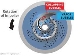
Cavitation is a system-based issue; it occurs when the net positive suction head available (NPSHa) at the pump intake is less than the net positive suction head required (NPSHr) by the pump to perform as shown on the pump performance curve. Resolving the issue can be as simple as partially closing a valve in the discharge line, or it could point to a more complex, systemrelated issue. When you are dealing with cavitation damage it is important to evaluate what changed in your system, to gather
data on the flow of the pump and the system head. Then you can compare this data to your design curve and make decisions about what changed and what changes need to be made to resolve the problem.
Erosion and corrosion have similar effects on a pump. Both result in material being removed from the parts of the equipment exposed to the fluid being pumped. Erosion occurs when tiny particles or solids are forced through the fluid stream and rub against the volute, the impeller and the discharge pipe. The result is wear of these surfaces—like taking sandpaper to a piece of wood. The most effective way to combat erosion is to use erosion-resistant materials in your equipment. Corrosion similarly removes material from the wetted parts of your pump. The difference between the two is that corrosion is happening all the time and to all parts exposed to the corrosive fluid.
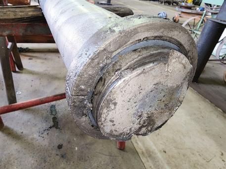
Similar to erosion, combating corrosion is tied to selecting the right materials for the fluid you are pumping. In sulfuric acid production, it is critical that you control the process and eliminate or minimize the formation of weak acid. Weak acid is formed when excess water gets introduced to the system. Weak acid can corrode materials that are suitable for strong acid in a very short amount of time, causing premature failure of equipment and ultimately costly repairs and downtime (see Fig. 2).

Foreign object damage is another cause of critical failures in pumps. This type of damage is just as it sounds—a piece of debris or an object that should not be in the fluid you are pumping gets drawn into the suction side of the impeller, wedging itself between the impeller and the volute, causing damage to the pump. The best case is that the centrifugal force of the pump is able to break the object it drew into the intake and you simply break a piece of your impeller. The worst case is that the object brings the pump to a quick and sudden stop resulting in a sheared impeller bolt, broken motor coupling, or broken shaft (see Fig.
3). Installing a suction strainer will help prevent foreign objects from entering the pump; but more importantly, ensuring that the rest of the system is well maintained and free of debris will prevent this type of catastrophic failure.
Finally, let’s look at some of the more insidious failures such as bearing failures, seal failures, and coupling failures. Often these failures result from one of two issues, the first being missed routine maintenance—in other words, failure to perform the manufacturer’s recommended service such as greasing the bearings or coupling at regular intervals. This leads to excessive wear, vibration and ultimately premature failure. The second and more devious method of failure comes when another part of the pump is not functioning correctly and, in turn, causes these components to fail. Having a pump that is not set properly, a shaft that is not properly aligned, or attaching a discharge pipe that places a significant amount of pipe strain on the pump all can lead to a misaligned pump that vibrates. Over time this vibration will cause the running components of the pump to wear excessively, causing the vibrations to further intensify and premature failure to occur. When vibrations begin to develop, it is imperative that a full analysis of the equipment is performed so the underlying issue is resolved.
As with any piece of machinery, having a proper maintenance program for your pumps is critical to their long-running operation. Being able to analyze why a failure occurred and what changes need to be made to prevent that same failure in the future will pay dividends throughout the plant. When in doubt, contact the company that supplied the original equipment and the engineer who designed the system to enlist their help in analyzing the issues that are occurring.
For more information, please contact Ravinder (Ricky) Jaswal (ravinder.jaswal@mail.weir) of Weir Minerals Lewis Pumps at (314) 272-6226 or visit the company’s website at www.lewispumps.com.q
Fig 1: An impeller damaged from pump cavitation.
Fig 2: Severely worn parts from weak acid.
Fig 3: A broken shaft, the result of debris inside the pump.
PAGE 18 Sulfuric Acid Today • Spring/Summer 2024 Feature

SARAMET® Acid Towers
CUSTOM TOWER DESIGNS TO MATCH YOUR PLANT NEEDS
• Achieves performance requirements in all plant operating modes
• Customized SARAMET® metallurgy is selected for each application (Dry, Inter, Final, ALPHA™ or Oleum Towers)
• Proprietary gas inlet nozzle designs engineered to eliminate localized corrosion
• Designed for retrofit or new tower installations
• Allows use of existing or new tower foundations minimizing installation time
• Scope of supply ranges from detailed engineering and manufacturing drawings with material supply, to complete EPC
• Full tower life cycle support is available from Worley Chemetics, including technical and inspection services
LEARN MORE
chemetics.info@worley.com chemetics.equipment@worley.com
WORLEY.COM/CHEMETICS
Innovations in sulfuric acid handling for enhanced efficiency and safety
Sulfuric acid, a cornerstone of numerous industrial processes, is pivotal in industries ranging from chemical manufacturing to mineral processing. However, its corrosive nature poses significant challenges in handling and application, necessitating continuous innovation to ensure operational efficiency and safety. Recent advancements in sulfuric acid application technology have revolutionized the landscape, offering solutions that enhance efficiency, extend equipment lifespan, and mitigate environmental risks. This editorial explores key innovations in sulfuric acid handling, sulfur gun design, and diverse nozzle designs, highlighting their transformative impact on industrial operations.
Understanding the challenges of sulfuric acid production
Producing sulfuric acid via the sulfur burning process is a multifaceted endeavor laden with challenges that can profoundly affect efficiency and profitability. Among these challenges are:
1. Vaporization and combustion efficiency: Efficient sulfur vaporization and combustion are essential for maximizing production rates and furnace efficiency. Inefficient processes lead to reduced yields and increased energy consumption, translating to higher production costs.
2. Equipment integrity: The integrity of equipment used in sulfuric acid production is critical for maintaining optimal performance. Improper droplet size and distribution can result in equipment build-up and damage, necessitating costly repairs and downtime.
3. Nozzle plugging: Nozzle plugging due to inconsistent droplet sizes or inadequate temperature control can significantly increase maintenance time and disrupt operations. Addressing this challenge requires reliable nozzle designs capable of withstanding the harsh operating conditions of sulfuric acid production.
Innovations in sulfuric acid nozzles and sulfur guns
In response to these challenges, Spraying Systems Co. offers a comprehensive range of sulfur burning nozzles and sulfur guns designed to optimize performance and increase production efficiency.
Steam jacketing: a shield against erosion
Steam jacketing on sulfur lines is a common practice for the piping network from the sulfur pit to the sulfur gun. Adding the steam jacket to the sulfur gun maintains the ideal temp for the acid to the tip. Steam jacketing serves as a thermal barrier, maintaining the molten sulfur at a consistent temperature to prevent the formation of high viscous sulfur and crystallization. This innovation is crucial in environments where temperature fluctuations are common, as
these can lead to plugging of the sulfur line and unexpected shutdowns.
By enveloping the equipment in a steamfilled jacket, the technology ensures that the acid remains at an optimal temperature, thus reducing the risk of corrosion and erosion. This extends the equipment’s working life and greatly reduces downtime and maintenance costs. Steam jacketing enhances operational efficiency and safety in sulfuric acid applications by providing precise temperature control, efficient heat transfer, corrosion resistance, and versatility in various equipment types.
Hydraulic nozzles
• CBA WhirlJet® Sulfur Guns: Spraying Systems Co. industry-standard sulfur guns have been trusted for decades, providing precise droplet control and performance unmatched. With tight droplet size control, these guns ensure efficient combustion and minimal maintenance downtime.
• BA WhirlJet® Hydraulic Nozzles: Renowned for their precision design and resistance to clogging, BA WhirlJet hydraulic nozzles produce small drops and ensure consistent droplet size and distribution, optimizing sulfur combustion and minimizing equipment build-up.
Air atomizing nozzles
• FloMax® Nozzles: With high turndown ratios for consistent performance across various operating conditions, FloMax nozzles offer versatility and efficiency, handling a wide range of flow rates and materials.
• SU89 Spray Set-Ups: Ideal for applications requiring fine droplet sizes and precise spray control, SU89 spray setups produce smaller drops compared to hydraulic nozzles, facilitating efficient sulfuric acid production.
Hybrid sulfur gun
Combining hydraulic and air atomizing functionalities, the hybrid sulfur gun enables quick changeover between nozzle types, offering flexibility in application and adjustment to performance requirements.
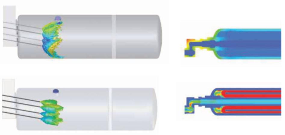
shows velocity.
Diverse nozzle designs for varied applications
Given the chemical’s aggressive nature, the application of sulfuric acid in industrial processes requires precision and adaptability. Recognizing this, Spraying Systems Co. has developed a wide range of nozzle designs and has been instrumental in meeting the diverse needs of the industry. From spray nozzles designed for optimal distribution patterns to injection nozzles tailored for precise dosing, the variety of available designs ensures that there is a solution for every application.
Each spray nozzle type is engineered with specific applications in mind, considering factors such as flow rate, spray pattern, and material compatibility. This specialization ensures that the equipment can handle the corrosive nature of sulfuric acid while delivering the desired performance. Comprehensive insights into various nozzle designs underscore their critical role in optimizing sulfuric acid applications across different industrial sectors.
Leveraging advanced spray technology for enhanced efficiency
In the dynamic landscape of sulfuric acid production, advanced spray technology

solutions offered by Spraying Systems Co. provide the tools needed to achieve unparalleled results. Computational Fluid Dynamics (CFD) modeling plays a crucial role in optimizing performance and identifying potential problems, ensuring efficiency and reliability in sulfuric acid production.
Conclusion
The innovations highlighted in this editorial represent significant strides towards safer, more efficient, and environmentally responsible sulfuric acid handling. By embracing these advancements, industries can achieve a balance between operational efficiency and environmental stewardship, ensuring a sustainable future for sulfuric acid applications. Continuously adapting is paramount in meeting the evolving demands of industrial processes, paving the way for safer and more efficient chemical processing methodologies.
Additionally, innovations in sulfuric acid application technology, such as improved sulfur gun design and diverse nozzle designs, have significantly improved safety, efficiency, and longevity in equipment used for distribution. Steam jacketing, for instance, serves as a thermal barrier, maintaining sulfuric acid at consistent temperatures to prevent plugging and unexpected shut down. Moreover, a diverse range of nozzle designs tailored to specific applications ensures precise control over droplet size and distribution, optimizing sulfuric acid handling across various industrial sectors.
In conclusion, innovations in sulfuric acid application technology have significantly enhanced safety, efficiency, and environmental responsibility in industrial processes. By embracing these advancements, industries can achieve a balance between operational efficiency and environmental stewardship, ensuring a sustainable future for sulfuric acid applications.
For more information, contact www. spray.com or (630) 665-5000. q
CFD shows the difference in wall impingement when using a hydraulic nozzle (top) and air atomizing nozzle (bottom).
FSI analysis of sulfur gun in harsh combustion environment. Top illustration is a thermal analysis; bottom illustration
PAGE 20 Sulfuric Acid Today • Spring/Summer 2024 Feature
BA WhirlJet ® hydraulic nozzles produce small, consistent droplet size and resist clogging.
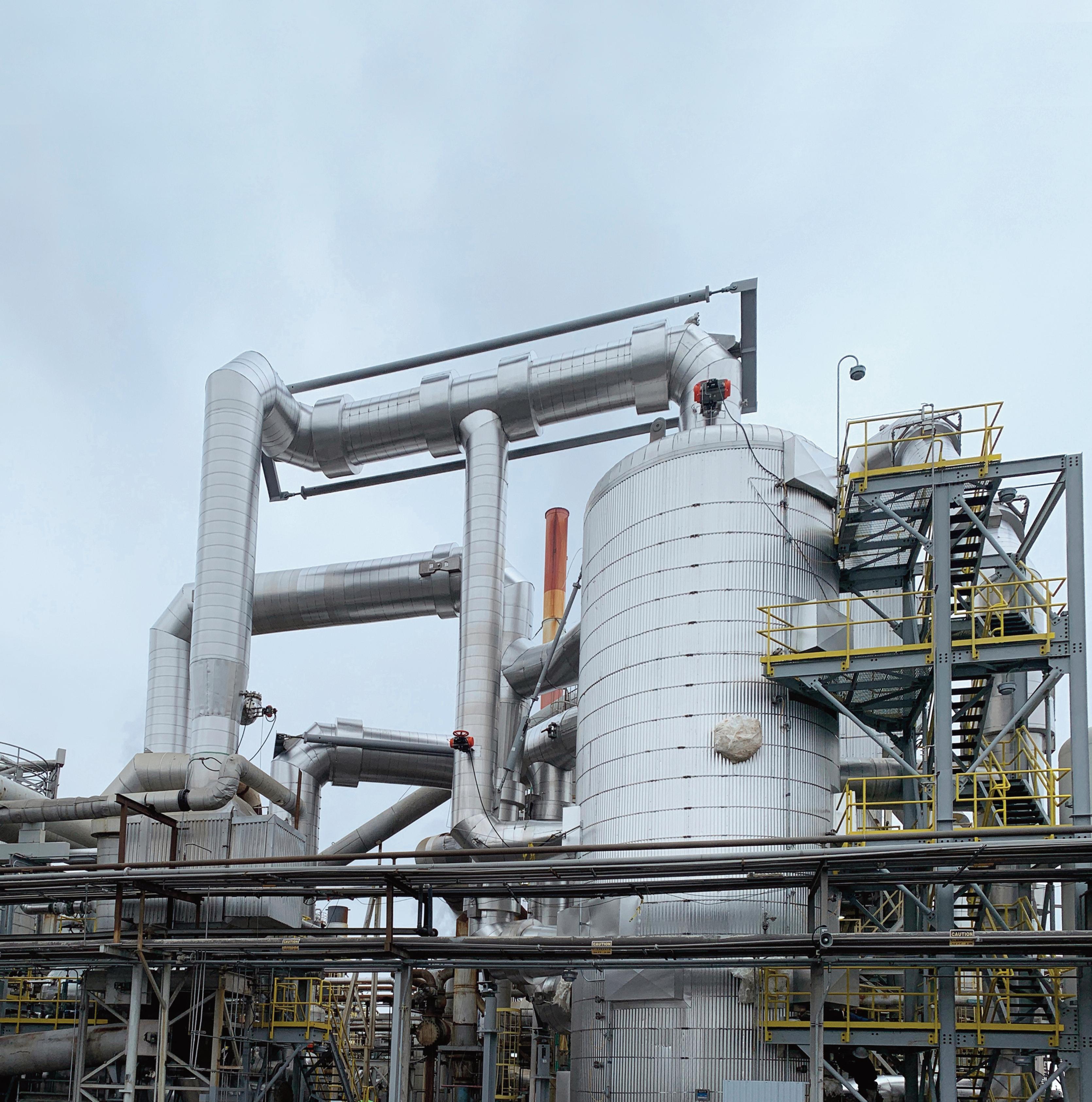
Engineering and Design for Sulfuric Acid Plants Moder n Technology and Equipment Design +1.604.681.2030 | sulfuric@noram-eng.com | noram-eng.com World Class

Can I really “absorb” pressure thrust with tie rods/control rods?
Customers often come to INTEREP asking for tie rods (also called control rods) on their expansion joints, stating that they want to “absorb the pressure thrust.” Sometimes they state it as more of a question than a request: “can I really absorb pressure thrust from this expansion joint if I put tie rods on it?”
Let’s get straight to the facts. Tie rods have one job: to hold back the immense pressure thrust (i.e. axial force put into adjacent piping) that metal bellows naturally create when they try to get back to their full, undeveloped tube length under pressure. However, their effectiveness hinges on a crucial requirement: zero axial compression. The moment the expansion joint shrinks even a fraction and ‘backs off’ from the limit setting on the tie rods, the pressure thrust returns in full force, turning system anchors into unwitting victims.
Now, the question on everyone’s mind is: “Why offer tie rods at all if they’re not the end-all-be-all solution?” Here’s the lowdown: they act as a failsafe; a safeguard against those nightmare scenarios
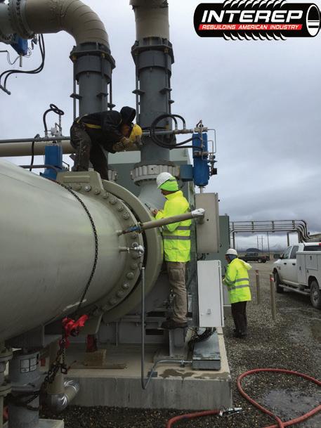
where system anchors fail to do their job. Sure, they might not be mandatory across the board, but when it comes to the kinds of expansion joints we like to use in the sulfuric acid world (large diameter, thick,
By: CJ Horecky, Executive Director, INTEREP, Inc.
multi-ply, and generally heavy-duty) tie rods are essentially a non-negotiable.
Around the converter in an acid plant, you’re dealing with consistent high temperatures, which is why you’ve got tie rods spanning most of your ductwork already. Acid plant industry standards call for tie rods to protect entire sections of ductwork from pressure thrust, rather than just isolating the expansion joint. Outside of the large diameter converter ductwork, like near your blowers, or in tight duct-runs where you can’t have thirty-footlong tie rods overhead, you have the same challenges everyone else in the industrial world has: pressure thrust from expansion joints.
Make no mistake, slapping on some tie rods and calling it a day is not going to cut it. The integrity of your piping system isn’t a puzzle where tie
rods are the missing piece. It requires a holistic strategy, with tie rods as one part of a grander design. It’s about understanding the forces at play and engineering a system that can fully integrate them, not get trampled by them.
For more information visit INTEREPinc.com; or contact CJ Horecky at 480-500-9161 or at the Sulfuric Acid Roundtable at Omni Champion’s Gate, Orlando FL, April 22-25. q
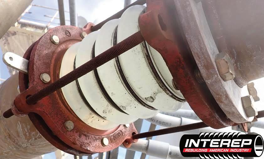
 INTEREP crews working on two tied universal expansion joints, installed due to the tight space constant created by the elbows seen at the top of the photo.
PAGE 22 Sulfuric Acid Today • Spring/Summer 2024 Feature
An INTEREP convoluted PTFE expansion joint, commonly seen in sulfuric acid plants, on which the tie rods have corroded and failed, allowing pressure thrust loose into the system.
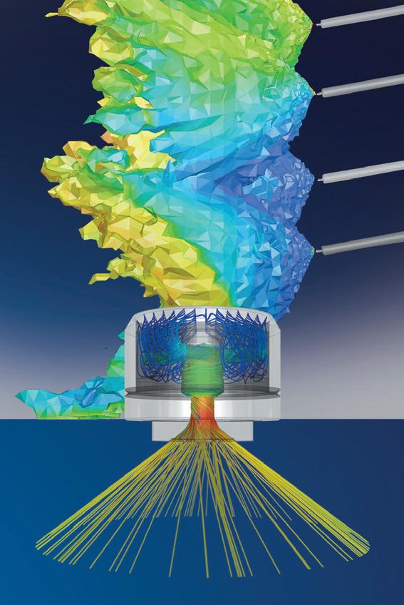
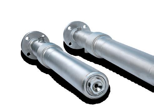

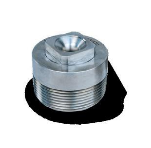
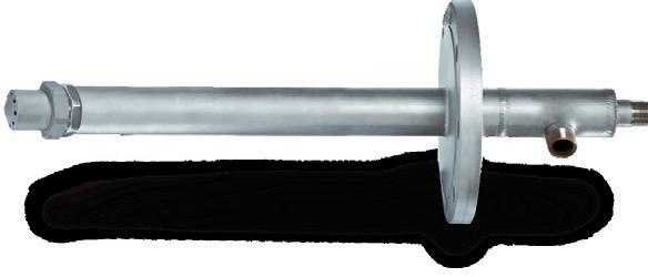


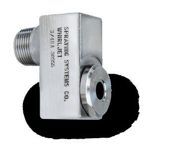
For unmatched service and support, visit spray.com or call 1.800.95.SPRAY
BA WHIRLJET
SULFUR NOZZLE
CBA WHIRLJET®
Increase Production, Minimize Waste in Sulfuric Acid Plants
SULFUR NOZZLE
SPENT ACID NOZZLES
FLOMAX®
CBA SULFUR GUN
Troubleshooting exchangers: design, maintenance & supply challenges
By: Ben Carris, Nesho Plavsic, Randal Sarrazin, and Werner Vorster, NORAM Engineering and Constructors Ltd.
This paper provides an overview of heat exchanger design fundamentals and a case study of the design and supply of a new NORAM Split Flow (SF™) exchanger replacing an old plate-style exchanger at a client’s acid plant. Design considerations such as co- and counter-current, as well as cross flow, are discussed before a review of typical gas exchanger styles used in acid plants and how the gas flow configuration impacts the tube metal wall temperatures.
The case study reviews a NORAM SF™ cold interpass exchanger and associated ducting recently supplied to a Mexican fertilizer manufacturer. The new exchanger was designed to operate over a wide operating range covering the current maximum production capacity, an ultimate target production capacity increase of 40%, and a turndown capacity of approximately 50% of the future capacity. A number of strategies were under consideration to reach the targeted plant capacity–and the exchanger, which was due to be installed in a planned shutdown in 2023, had to accommodate whichever strategy was eventually selected.
The 13ft diameter by 65ft high Radial Flow (RF™) exchanger, incorporating NORAM’s patented Split Flow (SF™) design, was built in one piece by a local fabricator and shipped 800 miles by road to the plant site where it was installed by the client’s construction contractor in July 2023. As the exchanger was installed in a new location, four new ducts were required. The ducts were fabricated in the United States and shipped about 1,700 miles by road. The ducts were assembled on-site and installed by the client’s construction contractor without any misalignment or fit-up issues.
As the exchanger had to be fabricated and delivered to the plant site in time for a major plant turn-around, there was a lot of pressure on the overall fabrication schedule, underscoring the importance of regular shop inspections (by a local inspector) and frequent visits by NORAM’s engineers to the fabricator to ensure the required quality had been met.
The cold interpass heat exchanger was installed and commissioned in 2023 and has been successfully meeting its performance requirements ever since.
Exchange design fundamentals
Heat exchangers play a crucial role in industrial processes, optimizing energy efficiency through the transfer of heat between two fluids separated by a heat transfer surface. A ‘typical’ exchanger design consists of a number of tubes contained within a
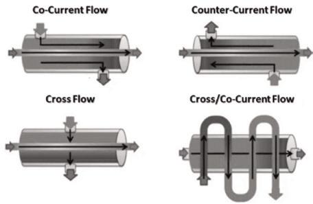
shell (outer vessel) with one fluid flowing through the tubes while the other flows over the outside of the tubes. Some common configurations are shown in Fig. 1.
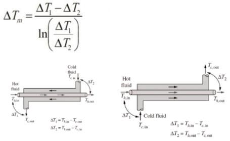
The driving force of heat transfer in an exchanger is the difference in temperature between the two fluids, expressed most commonly as the Logarithmic Mean Temperature Difference (LMTD) as shown in Fig. 2
The capacity of a heat exchanger to allow for conductive and convective heat transfer between the hot and cold fluids is represented by the overall heat transfer coefficient, U, which is influenced by the exchanger geometry and material. Together, these parameters affect the required heat transfer area and, in addition to hydraulic concerns, are the principal considerations in exchanger design. Exchanger temperature profile and heat transfer efficiency are key factors in the choice between countercurrent flow, co-current flow, and cross flow configurations, each presenting distinct advantages and challenges:
Co-current flow design: hot & cold fluid flowing in the same direction
• Temperature profiles approach equilibrium toward the outlet, limiting the driving force between fluids.
• Allows for a more uniform metal temperature along the heat transfer surface, reducing the risk of thermal expansion-relat-
ed issues or exposing the metal to extreme temperatures.
• Higher likelihood of an insulating, laminar boundary layer as the fluids flow parallel along the tubes, especially near the outlets.
Counter-current flow design: hot & cold fluid flowing in opposite directions
• Maximizes the logarithmic mean temperature difference, enhancing heat transfer efficiency.
• Allows for a more uniform temperature gradient across the heat transfer surface, reducing the risk of thermal expansion-related issues.
• Higher temperature difference along tubes helps disrupt the formation of laminar boundary layer that could hinder heat transfer.
Cross flow design: hot & cold fluid flowing in perpendicular directions
• Achieves moderate temperature differences between fluids.
• Produces asymmetric temperature zones, decreasing mechanical integrity from uneven thermal expansion.
• Promotes increased turbulence, mitigating the formation of laminar boundary layers and increasing convective heat transfer coefficient.
Optimizing design
Several exchanger designs and geometries evolved to transfer heat from hot to cold process gas streams in the sulfuric acid process as shown in Fig. 3. Singlesegmental exchangers combined the high LMTD of counter-current flow and turbulence of cross flow by directing the gas across the tubes with baffles but were still thermally inefficient along sections of parallel flow and produced high pressure drop as the number of tubes increased. The double-segmented design improved pressure drop on the shell side but still suffers from thermal inefficiency and introduces lowvelocity areas near the core that created cold and hot zones in the exchanger.
Radial flow exchanger design
• Utilizes an annular pattern with disk and donut baffles, directing flow from the inner core outward and from the outer annulus inward across the tube bundle.
• Ensures uniform flow and lower pressure drop losses by minimizing gas acceleration and deceleration.
• Features a radially symmetric thermal expansion, mitigating potential expansionrelated issues.
• Provides the flexibility of nozzle connections, allowing for diverse ducting layouts and orientations.
• Demonstrates higher heat transfer efficiency, reducing the required heat transfer area and overall size, consequently lowering manufacturing costs.
Overcoming design challenges in sulfuric acid plants
Gas exchangers in sulfuric acid plants face some unique challenges given the operating temperatures, gas compositions, and corrosion issues resulting from acid condensation. NORAM developed a variation of the radial flow exchanger, the Split Flow (SF™) exchanger, specifically to address these issues.
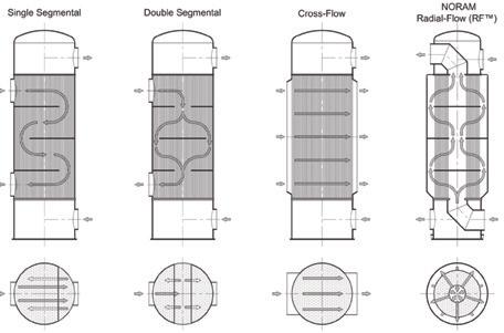
High temperature application
Some acid plants, typically metallurgical plants, require the use of a pre-heater to maintain gas temperatures in the plant. In such a configuration, a gas- or diesel- fired furnace is typically used to create a hot gas stream that is used to pre-heat the process gas. This gas-gas exchanger is installed
Understanding the intricacies of counter-current, co-current, and cross flow configurations laid the foundation for improved designs like the radial flow exchanger, which is a more advanced solution that combines the benefits of cross flow and counter-current flow configurations while solving the challenges associated with conventional exchanger designs. Thus, it became the industry standard in gas-togas exchanger design.
Fig. 1: Heat exchanger flow configurations.
Fig. 2: Log Mean Temperature Difference calculation for counter-current and cocurrent flow.
PAGE 24 Sulfuric Acid Today • Spring/Summer 2024 Feature
Fig. 3: Various shell-and-tube heat exchanger designs.
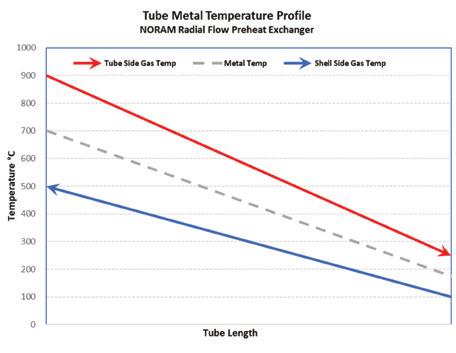
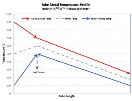
directly after the furnace, resulting in the possibility of the tube sheet being exposed to high temperatures exceeding the design limits of materials (especially in the case of gas maldistribution in the vestibule). This may limit achievable flue gas temperatures and reduce overall heat transfer and fuel efficiency, in turn requiring a larger exchanger with more heat transfer area.
The NORAM Split Flow (SF™) style of radial flow exchanger design diverts a portion of the cold gas directly to the tube sheet in a “cold sweep” arrangement. Coupled with the use of ferrules and an appropriate heat shield, the furnace can be operated at higher temperatures, which creates a larger thermal driving force while maintaining a tolerable metal temperature (as shown in Fig. 4). The increased thermal efficiency results in a smaller exchanger
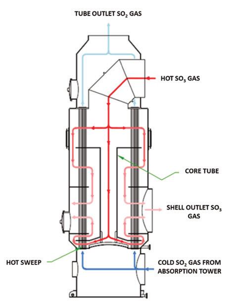
and cost savings due to the ability to operate the furnace at higher temperatures without compromising the integrity of the tube sheet.
Low temperatures & acid condensation
Acid condensation, particularly in SO3rich gas, can occur in cold heat exchangers (Cold, Cold Interpass / Cold Reheat) and SO3 coolers, leading to tube metal corrosion, sulfate formation on tubes, and decreased heat transfer performance. More frequent cleanings are required during plant shutdowns, increasing maintenance costs and lost production due to fouling and acid condensation.
In cold heat exchangers, the NORAM split flow mechanism incorporates a “hot sweep”, directing a small portion of hot gas to elevate the temperature of the cold tube sheet and the coldest portion of the tubes, above the acid dew point as shown in Fig. 5.
The bulk of the gas continues in the normal counter-current flow arrangement, ensuring efficient heat exchange. Both gas streams converge at a common exit duct, maintaining balanced pressure drop and flow through careful baffle spacing and geometry. Sulfate formation is minimized which reduces and/or eliminates the need for cleaning in addition to maintaining high heat transfer efficiency, contributing to overall plant operational reliability and performance.
Fig. 6 shows the increase of the mean “cold” tube sheet temperature from around 140°C in a counter-current exchanger to above 200°C using a “hot sweep,” significantly higher than the expected dew point of the process gas.
A further improvement is the use of ferrules to insulate the bottom tubesheet from cold inlet gas to minimize the risk of conden-

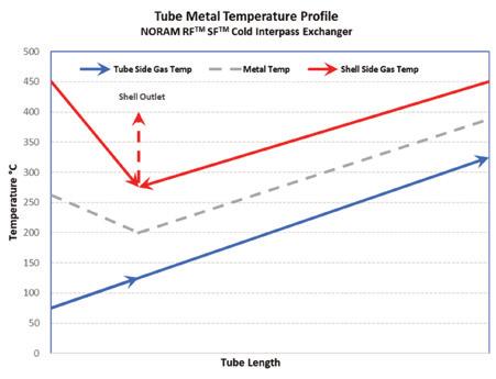
sation, thus reducing fouling and preserving heat transfer performance in the cold interpass heat exchanger (CIP).
Troubleshooting problems in exchangers
Exchangers in sulfuric acid plants are susceptible to various common issues, primarily stemming from acid deposition on metal from condensation and acid mist. The risk of these problems increases for exchangers in proximity to acid towers and significantly reduces their lifespans.
Acid condensation & sulfate formation:
• Acid condensation occurs when gas containing SO3 and H2O is cooled below its acid dewpoint, typically from contact with cold spots in exchangers.
• Higher dewpoint temperatures, caused by high humidity and SO3 concentration in the gas, increase the risk of condensation.
• Acid condensation on exchanger tubes and tubesheet is prevalent in cold exchangers, leading to the formation of sulfates that insulate the tubes and raise exchanger pressure drop.
• Corrosion caused by acid can damage the tube material, forming holes and causing leaks in the tubes.
Acid mist carryover:
• Acid mist carryover, particularly on the SO2 side of the exchanger, results from poorly performing mist eliminators in acid towers.
• High gas inlet temperatures entering absorption towers can cause excessive mist formation, exceed mist eliminator capacity,
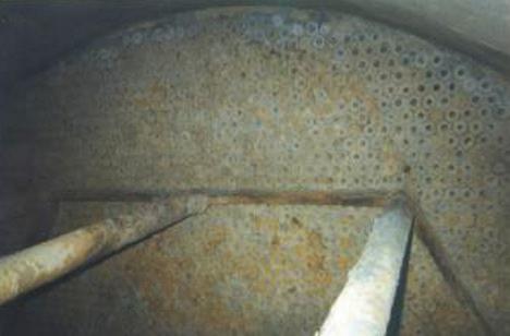
• Observing rising volumes of acid accumulation during routine exchanger drains of the SO2 side can indicate high acid mist carryover and poorly performing mist eliminators.
Corrosion and leakage:
• Monitoring the opacity of gas exiting the SO2 side drain can indicate SO3 leakage through corroded tubes.
• Process gas sampling and analysis of SO2 concentrations surrounding exchangers, conducted by third party organizations, can quantify the severity of a heat exchanger tube leak.
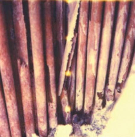
Remediation & Solutions
Cleaning during shutdowns:
• Fouling can be addressed by cleaning the exchanger during shutdowns, a procedure that is easier to perform on the inside of the tubes.
• Flooding the shell side with alkaline solution can remove sulfate buildup but is not recommended because it presents its own high-pH corrosion risks, and most exchangers are not designed to withstand the hydrostatic pressure of a flooded shell. Preventative measures:
• Emphasizing prevention over remediation, ensuring optimal drying tower absorption performance can maintain low process gas humidity and acid dewpoint.
• Ensuring that high-quality sulfur with low hydrocarbon impurities and acidity is fed into sulfur burning furnaces will contribute to dryer process gas.
and exacerbate corrosion and fouling issues.
Troubleshooting & Diagnosis
Sulfate formation:
• Monitoring the rise in pressure drop across the exchanger can help in detecting sulfate formation.
• Reduction in thermal performance of the exchanger over time is also symptomatic of sulfate fouling.
Acid mist carryover:
• Conducting a stick test on acid tower outlets can signal the presence of acid mist carryover.
• Regular inspection and maintenance of acid tower mist eliminators is essential to minimize mist carryover.
• Exchanger design: reducing the risk of cold spots by incorporating tube ferrules and employing appropriate flow arrangement.
• Application of corrosion-resistant materials in exchanger construction can mitigate corrosion risks.
Case study: design and supply of a cold interpass heat exchanger
NORAM recently designed and supplied a replacement Split Flow CIP for a
Fig. 7: Sulfate formation on an exchanger’s bottom tubesheet.
Fig. 8: Tube breakage from acid corrosion.
Fig. 5: NORAM Split Flow (SF™) “hot sweep” design for a cold interpass exchanger.
Fig. 6: Temperature profile of Split Flow “hot sweep” demonstrating the higher minumum metal temperature than a counter-current cold interpass exchanger.
Continued on page 26 Sulfuric Acid Today • Spring/Summer 2024 PAGE 25 Feature
Fig. 4: Pre-heat exchanger with Split Flow “cold sweep” operates with a lower maximum tube metal temperature than a true counter-current radial flow design.
Mexican fertilizer manufacturer that was planning on expanding their plant’s acid production by 40% with a turndown capability of 50% of the ultimate capacity. To achieve the target capacity, a major upgrade to the existing equipment and ducting would be required.
As expansion strategies were being developed for an upgrade scheduled to commence in a few years time, the existing CIP was nearing its end of life and had to be replaced independently before the rest of the plant. This imposed additional challenges to the design and supply of this exchanger.
Process design considerations
A number of strategies were considered to achieve the future target production capacity. As the expansion project would be implemented over several years, the exchanger had to operate within both current and future conditions inclusive of changing gas composition and temperature profiles; this required that the design accommodate a much wider operating envelope than is typical. A number of simulations were developed to ensure the exchanger would perform at each one of the expected operating points.
A split flow design was selected to mitigate the fouling risks on the “cold” bottom tubesheet of the CIP and ensure the mean metal temperature was kept above the acid dewpoint. In addition to the split flow design, ferrules were inserted into the cold end of the tubes to further increase the tubesheet temperature, as shown in Fig. 9.
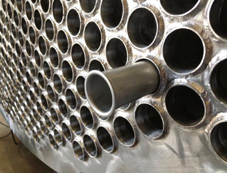
The compact design of the radial flow design allowed compliance with size restrictions while meeting performance requirements.
For several reasons, the exchanger would be installed in a new location on the plant site. Additionally, the plant layout would change during implementation of the various stages of the project as new / replacement equipment is installed and old equipment removed. Therefore, some of the new ducts connected to the CIP were considered temporary. At the time of implementing the CIP replacement, the future plant layout was still evolving. The nozzle entrance to the shell through the top of the exchanger (shown in Fig. 10) provided flexibility for duct routing, which was demonstrated when the location of the converter was changed during the design of the exchanger. Precise measurements, aided by plant 3D scans and old ducting design drawings, ensured a seamless fit during installation, minimizing downtime.
Fabrication / supply chain
Choosing a fabricator involved careful consideration of factors beyond cost, including:
• Prior experience with similar projects.
• Material expertise and dedicated stainless steel facilities to prevent cross contamination.
• Reputation.
• Location–long distance shipping of materials and final equipment increases the project lead time.
The selected Mexican fabricator possessed the necessary experience and dedi-

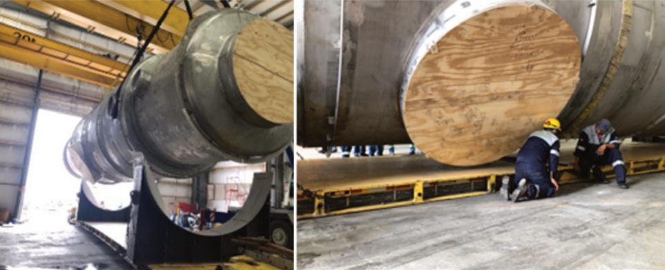
cated stainless steel fabrication capabilities, aligning with the project’s requirements. A rigorous quality plan was developed (and adhered to) to ensure a high-quality heat exchanger.
Mechanical design
The new exchanger is about 64 ft tall with a diameter of approximately 13.5 ft containing 1,370 tubes, and is predominantly constructed in 304L stainless steel, except for the corrosion-resistant 316L steel at the bottom vestibule.
One of the key design constraints of the exchanger was the shipping envelope.

The project’s tight schedule, dictated by a plant shutdown planned for June 2023, emphasized the importance of frequent inspections by a local inspector and NORAM engineers to maintain fabrication quality and meet deadlines. Although the long lead time items such as tubes and tubesheets were ordered at the onset of the project, delays in the delivery of the tubesheets nearly derailed the project.
Custom steel saddles were fabricated to secure the exchanger to the shipping truck bed for its one-week journey of around 800 miles from the fabrication shop to the project site.
Ducting was fabricated by a US supplier and shipped almost 1,700 miles by road to the plant site.
Installation & commissioning
Efficient plant shutdown management was crucial for minimizing construction time. The location of the new exchanger adjacent to the old one avoided the need for demolition as part of the shutdown. Rather, the new exchanger could be installed in place while the plant was operating with the scheduled shutdown only required for the ducting tie-ins.
Following the successful installation and commissioning in July 2023, the exchanger met performance requirements, demonstrating the efficacy of the design.

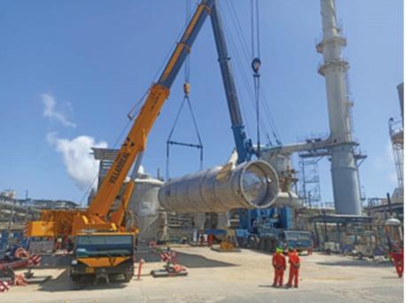
For more information, please visit www.noram-eng.com. q
References
• (Fig. 1) Tien, Tan & Vu, Quang & Duy, Vinh. (2022). Novel designs of thermoelectric generator for automotive waste heat recovery: A review.
• (Fig. 2) www.engineeringunits.com
• (Fig. 4) Metal temperature is presented as the mean temperature of the two fluids for ease of visual comparison.
Fig. 9: A protruding ferrule that would be welded flush to the end of the tube to insulate the tubesheet from the incoming cold gas.
Fig. 10: The shell’s inlet nozzle entrance through the top of vestibule allows duct connections from any direction.
Fig. 11: The exchanger during shop-fabrication.
Fig. 12: Loading the exchanger for shipping to site.
Continued from page 25 PAGE 26 Sulfuric Acid Today • Spring/Summer 2024 Feature
Fig. 13: Installation of the exchanger.
ALPHA-CORR TYPE III ACID BRICK
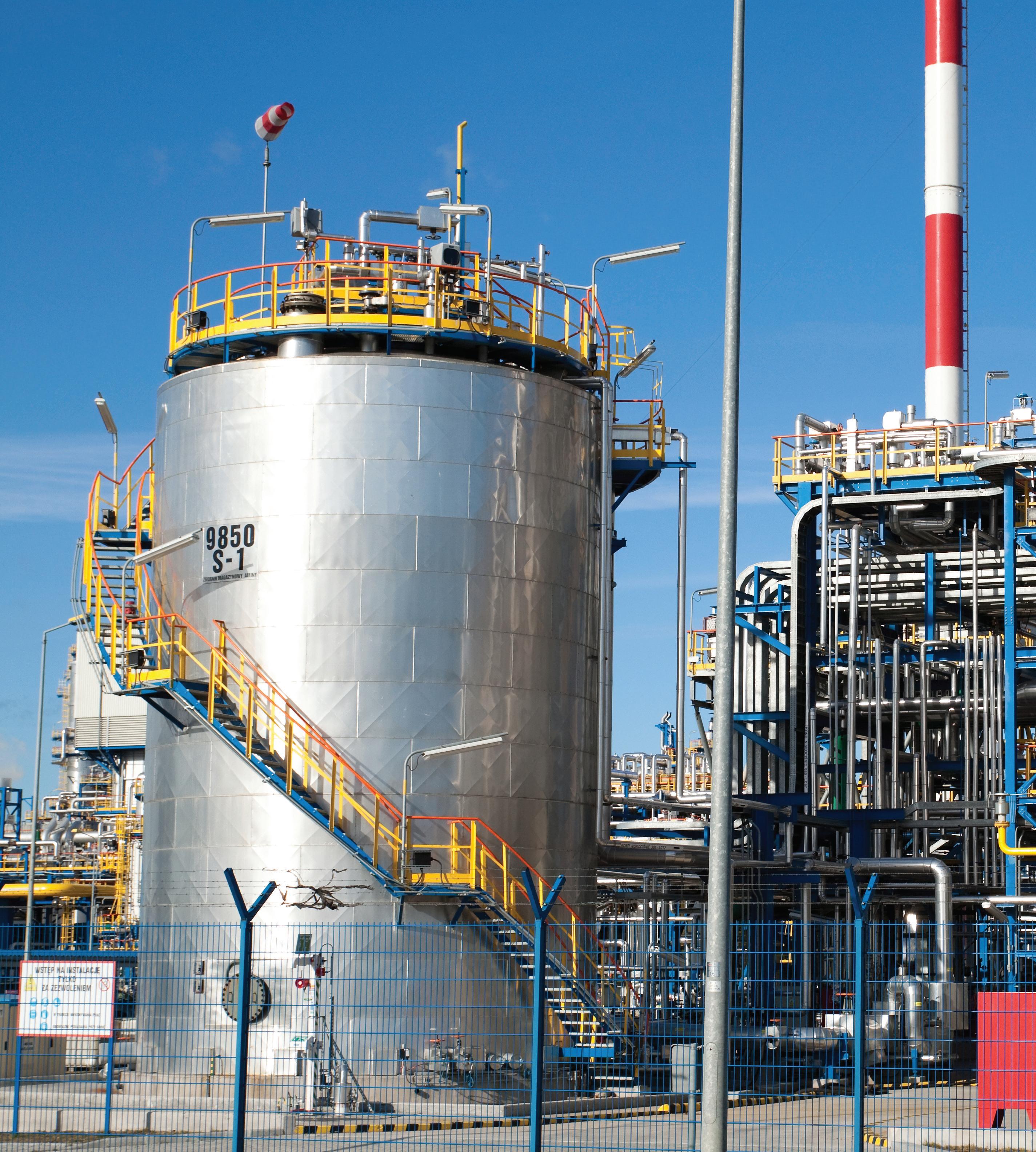

AvAilAble in the USA todAy
From our strategic location in Houston, TX, we are able to supply a variety of brick shapes (straights, arches, wedges, keys) and sizes from stock for immediate purchase.
Please reach out to us for technical data and pricing. Samples available upon request.
Meeting ASTM C279 standards for use in new construction and refurbishment of existing structures in sulphuric acid plants including towers, process vessels, floors, sumps, pits, etc.
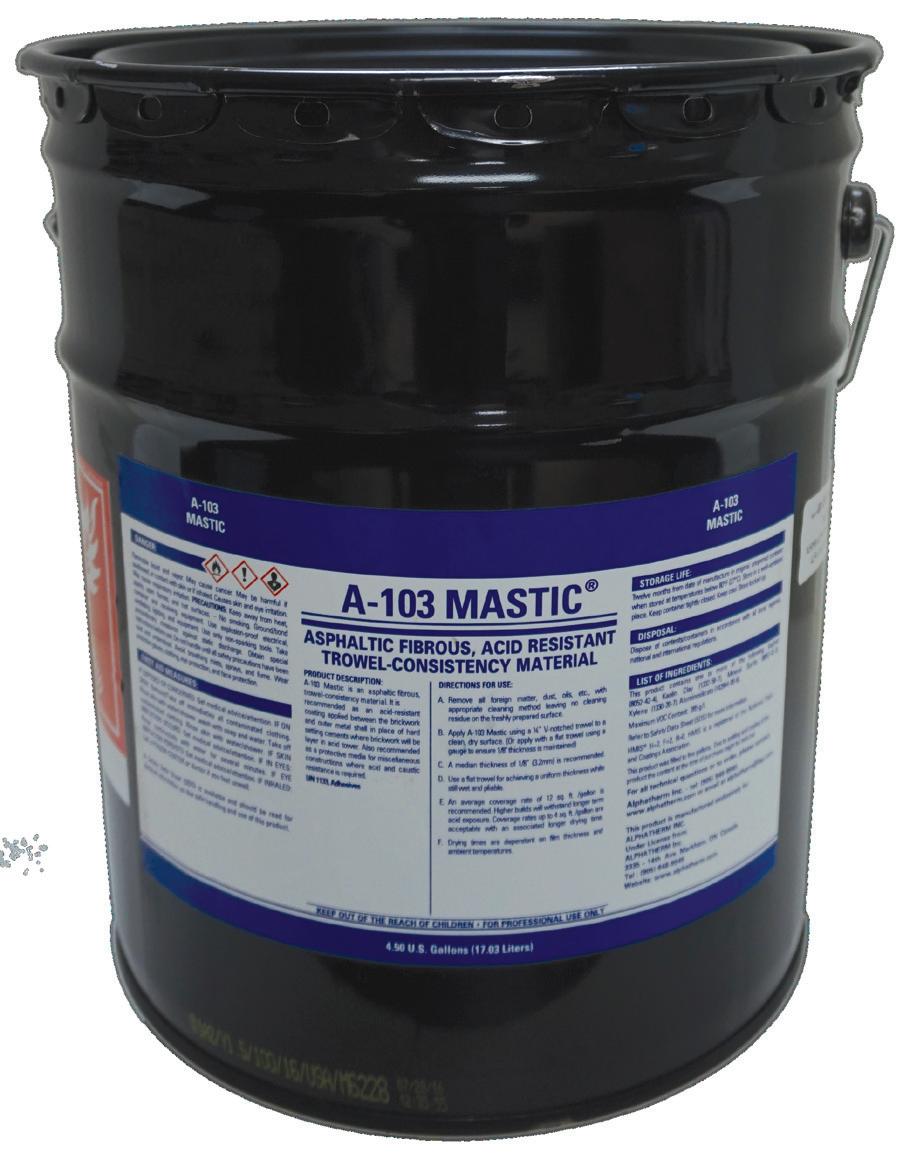
Industrial Linings for Sulphuric Acid Plants. Absorption Towers, Pump Tanks, Sulphur Pits, Secondary Containment, Acid Resistant Linings.
Acid Brick, Acid Resistant Mortar, Membranes, Carbon Brick, Polymer Concrete, Refractories, Teflon, Ceramic Paper and Blanket, Ceramic Rope, Borosilicate Block
A-103 MASTIC®
A-103 Mastic® is Still Available and in Stock in warehouses in USA and Canada. Made from the original recipe.
When your plant has a product that has proven successful for over forty years, why change? With this in mind, Alphatherm Inc. purchased the recipe of Pecora A-103 Mastic® to keep this integral piece of the Sulphuric Acid Tower lining system intact. Made from the same ingredients with A DECADES OLD RECIPE, A-103 continues to be the workhorse membrane in Acid Plants worldwide.
Accept No Imitations!
This is THE ONLY A-103 Mastic® made with the original Pecora recipe.
A-103 MASTIC is a registered trademark of Alphatherm Inc.
Alphatherm Inc. | www.alphatherm.com | Tel: (905) 948-9949 | Email: alphatherm@ilap.com
When working with corrosive liquid chemicals, you need the best protection against liquid chemical splashes. The right protective garment assists in reducing worker injury and minimizes the risk for accidental skin contact with chemicals.
Choosing protective garments made with GORE-TEX ® Chemical Splash Protective Fabrics provides exceptional liquid splash protection without sacrificing comfort.

EXP expands sulfuric acid knowledge base
Guy Cooper, P. Eng., joins EXP
Guy Cooper has joined EXP as Director, Marketing and Sales for EXP Houston’s Oil, Gas and Chemicals Group. Cooper is responsible for business development and sales for EXP’s sulfuric acid market. He will be supporting the Brampton, Ontario, and Houston offices from his Vancouver office. He comes to EXP with thirty years of sulfuric acid experience. A process engineer by training, Cooper is responsible for starting the sulfuric acid group at NORAM in 1991. He was director of the acid group from 2010 to 2020. EXP offers complete services for the sulfuric acid industry including engineering studies, equipment design and supply, project management, and turnkey acid projects.

For more information, contact Guy Cooper at (604) 724-8219 or guy.cooper@exp.com.
Greg Bellamy, P. Eng., joins EXP
Greg Bellamy has joined EXP as Mechanical Engineering SME. Greg will work out of EXP’s Burnaby (Vancouver), BC office as part of EXP’s global sulfuric acid team with their Oil, Gas and Chemicals Group. Greg brings 30+ years of experience with sulfuric acid equipment and ducting design, including the development of new technologies and products, to apply to EXP’s current roster of sulfuric acid projects presently being executed from the Brampton, Ontario, and Houston offices. Greg received his Bachelor of Applied Science degree in Mechanical Engineering from the University of British Columbia in 1989. After a brief period as a maintenance engineer, he joined NORAM Engineering and Constructors where he rose to Chief Mechanical Engineer, a position he held for over 10 years. In addition to Greg’s long experience in sulfuric acid, he has worked on projects in the petrochemical, specialty chemical, and electrochemical industries. Much of this work involved very corrosive or high temperature environments.

For more information, contact Greg Bellamy at (778) 885-4087 or greg.bellamy@exp.com. q

 Guy Cooper, Director, Marketing and Sales, EXP
PEOPLE ON THE MOVE PAGE 28 Sulfuric Acid Today • Spring/Summer 2024 Department © 2023 LAC-MAC LIMITED R-MOR PROTECTIVE WEAR is a trademark of Lac-Mac Limited © 2023 W. L. Gore & Associates, Inc. GORE, GORE-TEX and designs are trademarks of W. L. Gore & Associates
Greg Bellamy, Mechanical Engineering SME, EXP
Garments and fabrics are certified to NFPA 1990 Standard (NFPA 1992 - Specific) Phone: 1-888-452-2622 Email: info@lac-mac.com Made with www.lac-mac.com Optional Link in and join the discussion with industry leaders, professionals and consultants. www.linkedin.com/groups/2024262 Hosted by ® ASSOCIATES SulfuricAcid T O D A Y Sulfuric Acid
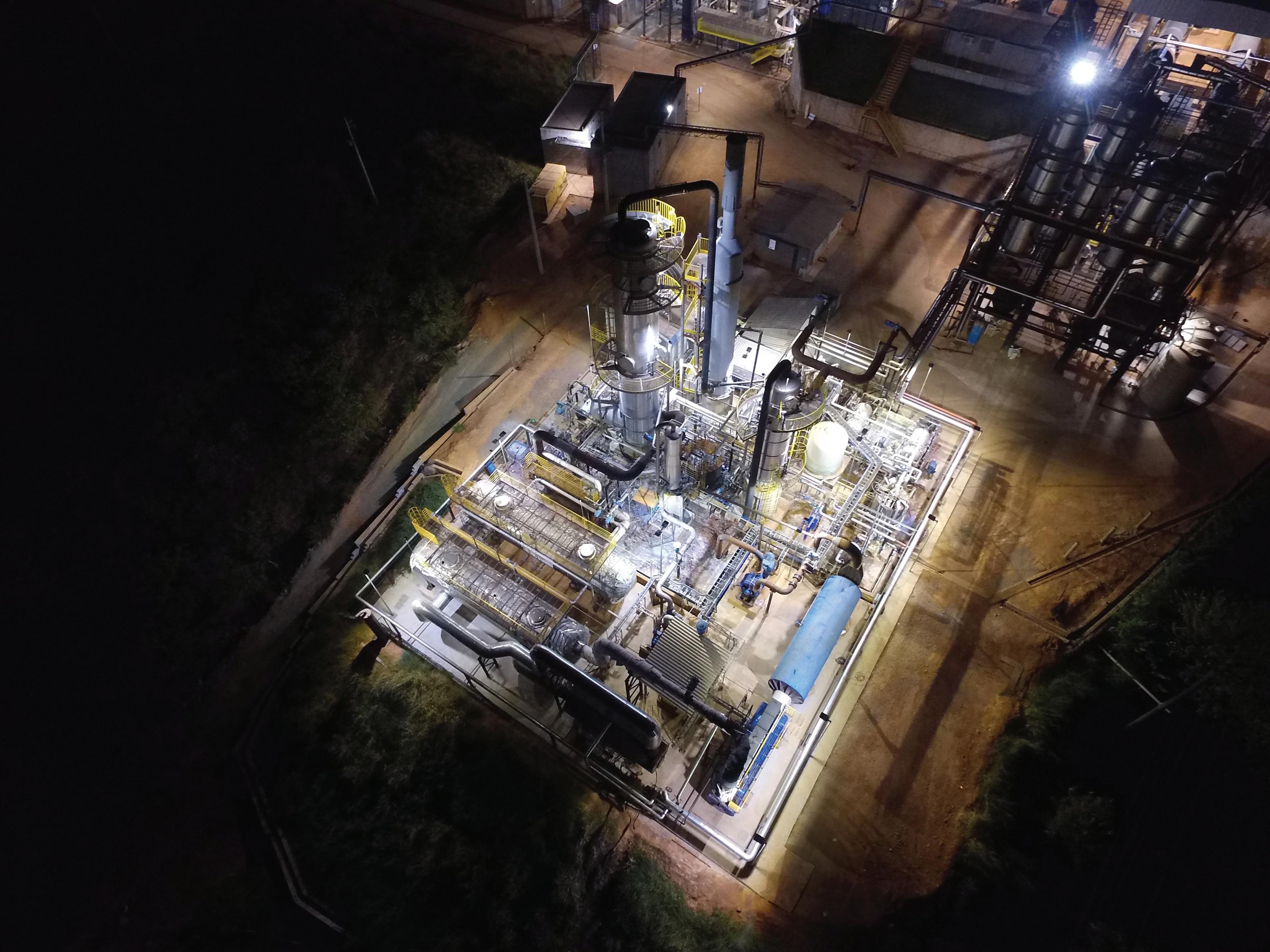

Engineered SOLUTIONS to your NEEDS
Wet electrostatic precipitator technology for sulfuric acid plants
By: Gary Siegel, Marketing Director, Beltran Technologies Inc
Sulfuric acid and lithum production
Current global production of lithium is currently well below worldwide demand, which has risen in recent years due to the increase in electric vehicles projected to eliminate petroleum-powered cars, trucks, and trains in the next 20 years.
Lithium is commercially extracted from five minerals and the most important mineral considered is spodumene. The extraction process entails initial crushing, then roasting at 212 degrees F, more grinding, and sulfuric acid leaching at 482 degrees F. This extraction method requires large quantities of high-grade sulfuric acid.
Wet electrostatic precipitators (WESPs) are used in metallurgical acid plants to protect the catalyst beds. These plants are usually non-ferrous smelters processing copper, zinc, lead, nickel, molybdenum, zirconium, and gold ores. WESPs are also used in spent acid recovery sulfuric acid plants where reprocessed or “spent” acid is converted into SO2 feedstock for the formation of new sulfuric acid. Another application for WESPs is to protect the sulfuric acid plants used to reduce SO2 and SO3 emissions from heavy oil and boilers where the fuel has high concentrations of sulfur.
WESPs efficiently collect sub-micron dusts and acid mists. These fine particulates usually contain heavy metals, such as arsenic, lead, zinc, cadmium, and other metals depending on the content of the ores. The emissions from these metallurgical processes can contain flotation oils used to separate the various constitutes in the ore, such as sulfides. These oils evaporate in the high temperature of the metallurgical process, condense into mists in the quenching section of the gas cleaning plant, and are then collected by the WESP. WESPs are also used for tail gas cleaning where it is necessary to remove particulate, mists, and aerosols as we as reduce visible emissions.
Advantages of WESPs
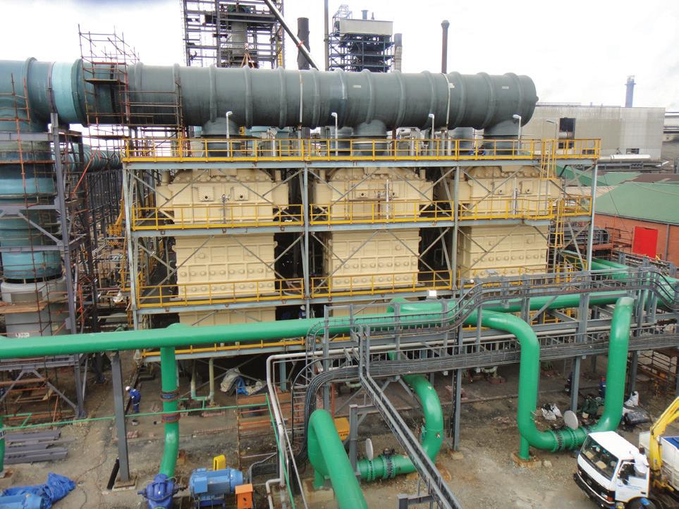
The advantages of using a WESP versus other types of gas cleaning equipment is that WESPs efficiently collect submicron particulate, mists, and aerosols with lowpressure loss since the internal structure is open tubes, which are not easily plugged, restricting gas flow. Another advantage of WESPs is that they can remove dusts that are conductive or have high resistivity, which are problematic for dry ESPs. Since a lot of metallurgical dusts have high resistivity, the wet environment of the WESP coats the particulate with moisture, which makes the dust conductive and collected with high efficiency.
WESPs operate by charging and collecting particulate, mists, and aerosols with a corona formed by the collector surfaces and the sharp pointed discharge electrodes. High voltage power charges the WESPs at high voltage, usually between 30 and 75 kilovolts depending on the WESP design and the process gas conditions. The WESP is usually constructed with a collector formed of tubes or plates with discharge electrodes held in the center of the collector structure by a high voltage frame which is supported by non-conducting insulators. Since the process gases are saturated and contain electrically conductive mists and aerosols, the insulators are operated dry, being purged by dry, clean, and heated purge gases, usually ambient air. The WESP can be operated either by the collection of liquid acid droplets, mists, and aerosols then flushing the collector plates, or with the operation of continuous fogging sprays into the collector section. WESPs usually have deluge or wash nozzles mounted to periodically wash the WESP of solids and collected particulate, which may not be removed by the draining acid/water collected by the WESP.
WESP design
The collection efficiency of the WESP is expressed in the DA equation and is an exponential function of three parameters: 1) collector surface area (A); 2) gas flow rate (F); and 3) drift velocity (w). These are really two parameters, A/F, which is related to the size of the WESP box, and w, which is proportional to the useful applied electrical power to the process gases. Since the
efficiency is proportional to the product of these two parameters, it is possible to design a WESP with a large box and low power, or a smaller box and higher power, each with the same efficiency. Since the consumption of electrical power for WESPs is usually low compared to other gas cleaning equipment, such as venturi scrubbers, bag filters, or other types of high-pressure devices, and since WESPs are constructed of expensive corrosion resistant materials, it is better to maximize w and minimize A/F (the size of the WESP). The exponent in the DA equation can be substituted with the parameters: voltage, tube or plate length, inter-electrode spacing, and gas velocity through the collector. The efficiency increases with greater field strength (operating voltage divided by inter-electrode spacing), collector length, and reduced process gas velocity.
The collection efficiency of the WESP varies with the size of the particulate, mist, or aerosol. Since gas phase reaction and evaporation/condensation form particles around 0.1 to 1.0 microns, considerable acid mist and particles form in this size range. As particles increase in size from the submicron range, they are more easily collected, since field charging increases. Also, as particles decrease in size from the submicron range they are more easily collected, since diffusion charging increases. Therefore, the collection efficiency curve versus particle size forms a U-shaped curve with its minimum in the submicron range. The collection efficiency is also related to corona power of the WESP, with the minimum efficiency increasing with greater corona power. To minimize the size of the
WESP and maximize operating efficiency, the WESP should be designed to maximize w, the drift velocity, or the rate at which particulate, mists, and aerosols move to the collector plates.
WESPs can be designed with various collector shapes: flat plates, vertical round tubes, hexagonal tubes, or square tubes. Historically, WESPs were built with round tubes and flat plates. The original acid mist WESPs were built with round tubes at the beginning of the last century. However, as the flow rate increased, the diameter of the tube became larger, which required higher operating voltages. The electrical power supplies at that time were limited in design and could not operate reliably at very high voltages, above 80 kilovolts. After that, WESPs were built with multiple smaller tubes or flat plates. Early WESPs were built from lead to resist the corrosion of sulfuric acid, so it was more economical to use larger diameter tubes and reduce their number, since lead construction was problematic due to lead’s low mechanical properties and high density. More modern WESP designs, utilizing other corrosion resistant materials, such as conductive graphite composites or chrome-nickel-molybdenum alloys, can be built in more efficient and economic configurations.
The round tube design has the disadvantage of wasting space in the vessel due to the nesting of the round tubes, so round tube WESPs require larger size vessels, or if not increasing the size of the vessel, then the gas will flow through at a greater velocity and require longer tubes for comparable collection efficiencies. This then requires the WESP to be considerably taller and the tubes longer for the same efficiency. This has a further disadvantage: that the high voltage discharge electrodes are longer, and the electrodes have a greater likelihood of swinging or vibrating during operation. This results in sparking and causes the WESP to operate at lower field strengths and voltages, lowering operating power and efficiency.
There is a major economic disadvantage of designing WESPs with round tubes: the surface area on the outside of the round tube is wasted. Only the surface area of the inside of the tube is utilized for collection; therefore, the round design has to use twice the collector material to obtain the same collector surface as the flat plate, hexagonal, or square tube design.
The obvious apparent feature of the round tube is the uniformity of the distance from the collector surface to the discharge electrode. Early lead designs utilized lead wires, supported by a metal core. In that
PAGE 30 Sulfuric Acid Today • Spring/Summer 2024 Feature
Beltran WESPs at Mopani Copper Mines
case, since a wire was the discharge electrode, the spacing between the collector and corona wire was constant around the circumference. However, wires are problematic since they break and short out the WESP, creating unreliable performance. Also, wires had to use lead weights at the bottom to keep the wires straight and aligned in the center of the tubes. This type of structure is susceptible to swinging, which causes poor WESP efficiency and unreliable operation. Most modern round tube WESPs use spiked discharge electrodes or solid pipe masts; however, this defeats the purpose of having a round tube design, since the spikes produce an asymmetric distance from the spike to the round wall, with the resulting asymmetric field strength and build-up of solids on the tube wall.
Today, modern WESPs are engineered using advanced materials of construction which utilizes the advantages of other shape collector tubes, such as the hexagonal and square tube.
The most efficient design when considering collection efficiency, compactness, and economic design is the square tube collector configuration. The square tube collector completely utilizes the cross-section of a square or rectangular vessel, and can be effectively utilized in round and hexagonal vessels. Due to the square tube’s high utili-
zation of the vessel cross-section, it can be operated at a lower velocity so that the required tube length is lower, making it more efficient and easier to wash, since the wash sprays penetrate the collector. The high voltage frame is also more rigid, does not swing, and stays more accurately aligned, resulting in more efficient and reliable performance. Because of the shorter tube length, lower stabilizing insulators are not required, and the insulators can be mounted on the clean gas side of the WESP, reducing the requirement for heated purge air and resulting in more reliable WESP operation.
Since the WESP collection efficiency is increased with increasing corona power, multi-pointed star discharge electrodes are utilized to maximize corona power and WESP operating efficiency. Multi-pointed star discharge electrodes overcome the problems of current suppression of space charge effect, whereby the corona power is significantly reduced by the high concentration of submicron particles, mists, and aerosols present in the process gases. This reduces the corona power of the WESP operation and can lower the collection efficiency. The multi-pointed stars charge and repel some of the submicron particles, and then enable the next star to increase its corona power, repeating this phenomenon almost 100 times as the gases flow up the

tube. This type of electrode can produce considerable efficiency in single or multiple pass WESPs, usually utilized in acid plants.
WESPs can be set up in various configurations, such as: single WESPs; two WESPs in series; two WESPs in parallel; and multi-WESPs in parallel and two in series. Smaller gas flows are usually treated with one WESP. This also depends on the efficiency requirements; however, one WESP unit can produce reliable service at 99.5% efficiency, for smaller flows. Typically, plants have two WESPs in series, so that one WESP can be washed while the other operates. Sometimes two WESPs are designed to be utilized in parallel, for similar purpose. Two in series has the advantage of the first WESP overcoming the current suppression condition, while the second WESP operates at full power. This will depend on the gas flow rate, inlet and outlet process conditions, amount of particulate, mist and aerosol at inlet and outlet, etc. Larger plants will require more WESPs in parallel and usually two WESPs in series; therefore, one WESP can be taken offline for maintenance, or washed online.
Materials of WESP construction
WESPs are being built of metal al-
loys, thermoplastic materials, thermosetting materials, and conductive graphite composite materials. Metal alloys are expensive and have extended delivery time, but their biggest disadvantage is the unreliable performance with regard to corrosion. The sulfuric acid WESP operates in highly corrosive environments, including sulfuric, hydrochloric, and hydrofluoric acid and other impurities, as well as increased temperature. Because of the high cost of more robust chrome-nickel-molybdenum alloys, like C-276, C-22, and C-2000, designers are attempting to utilize less corrosion resistant alloys like AL6XN and SMO 254, with resulting corrosion problems in some applications and conditions.
The Beltran WESP manufactured with conductive graphite composite materials have the following advantages:
• Highly corrosion resistant
• Have good mechanical properties
• Electrically conductive
• Homogenous
• Do not require water/acid film to ground WESP
• Fire retardant and thermally robust
• Cost effective
For more information, contact Beltran Technologies, Inc., at (718) 338-3311 or info@beltrantechnologies.com; or visit www.beltrantechnologies.com. q
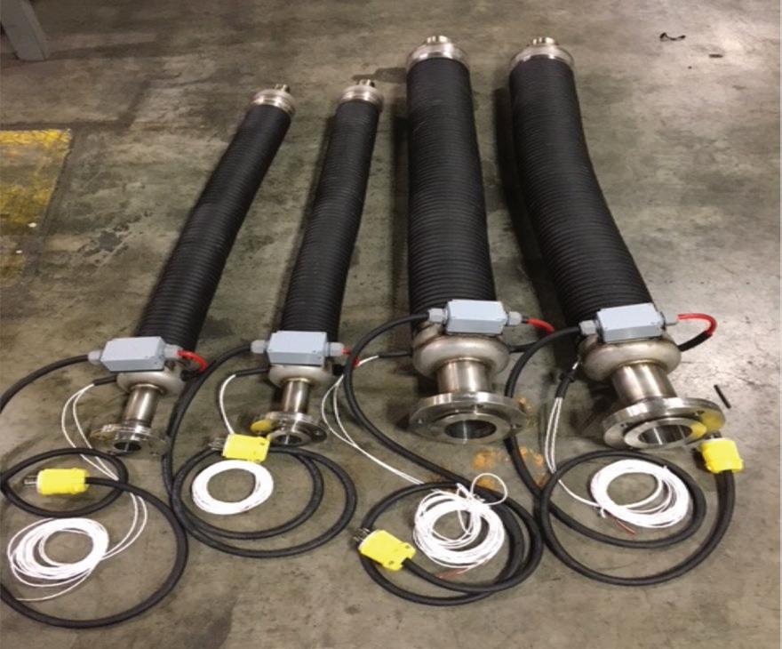
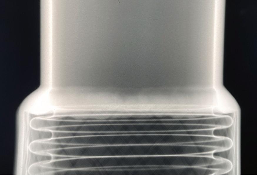
FLEX HOSE ASSEMBLIES DESIGNED FOR SULFURIC ACID PRODUCTION 100% Radiographic Weld Inspection Heat
for Injecting Molten
the Burner Safety and Reliability are second to none when it comes to plant operations. Full Penetration Welds create a seamless connection, minimizing risk. All welders are certified to ASME BPV Code Section 9. 100% Radiography - Inspecting pipe welds using 100% radiography is a crucial practice in ensuring the quality, reliability, and safety of welded joints. Heat Traced, Teflon® Lined, Composite, and ALL Hose Requirements Contact John Czerwinski: jczerwinski@branhamcorp.com | 502-649-4929 branhamcorp.com
Traced Hose
Sulfur into
Sulfuric Acid Today • Spring/Summer 2024 PAGE 31 Feature
Chemetics’ stainless steel radial flow converter: celebrating 40 years
Radial flow converter
In 1978 Chemetics invented and patented the Stainless-Steel Radial Flow Converter. Over the years, the design has continued to evolve to push improvements in performance, reliability, and manufacturability. The Stainless-Steel Radial Flow Converter continues to be the ideal industry solution to replace converters approaching their end of life, and for new acid plants.
Over the past 40+ years, Chemetics has supplied more than 70 radial flow converters with 304/304H stainless steel utilizing curved supports connecting the center core and outer shell in a full-welded all stainless steel design. This has allowed the converter to be designed for pressure conditions, thermal growth, and heat cycling while using a thinner stainless steel material. This design is well proven with existing installations demonstrating almost zero internal bypass with zero external gas leaks and virtually zero maintenance for 35+ years.
The flexibility in its design has allowed for internal gas-gas heat exchangers and/or superheaters to be installed inside the core which is a characteristic of all Chemetics stainless-steel converters. Installing an internal gas-gas exchanger and/or superheater inside the core will overall reduce cost and plant footprint while eliminating the need for certain hot gas ducts (i.e., Bed 1 outlet) that are likely to experience thermal stress and leakage. Fig. 1 shows a Chemetics radial flow hot heat exchanger being installed into a modular Chemetics converter at a metallurgical acid plant.
These benefits continue to outweigh those of alternative stainless-steel converters making it the go to replacement solution for mechanical integrity, improved performance, and start-up.
Modular fabrication
Chemetics has extensive experience in supplying modularized radial flow converters across the globe. Modularization simplifies freight and allows for controlled shop fabrication which improves quality while speeding the overall assembly process.
Modules are constructed concurrently by levels (see Fig. 2), three to six levels per converter. Staggering delivery by level accommodates the construction schedule leading to shorter timelines requiring just a single crew daytime assembly labor team on site. It is typical to achieve a complete converter replacement within a three- to

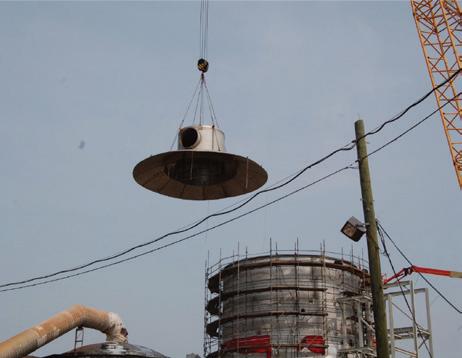
four-week shutdown for converter retrofit projects. With any design configuration, the Chemetics converter can be designed and fabricated into modules that best fit the project requirements.
Time-tested design
The curved supports, disc heads, and round gas nozzles in every Chemetics stainless steel converter are designed for thermal growth and allows for resistance and thermal distribution of the various operational loads. This design feature allows for the core and any supported internal heat exchangers to gradually expand with the entire converter without inducing unwanted local stresses, which could lead to leakage if the design does not minimize those stresses below the limits of the materials of construction. The Chemetics design is well proven, showing no signs of gas inlet or outlet leakages, or converter shell or core damage from these type of stresses. Chemetics’ converter design does not
use any flat surfaces for the roof, nozzles, or supports. Flat surfaces are prone to unwanted leakage from stresses associated with axial expansion. Post supports, which tend to tilt over time resulting in grate collapse or leakage, are also not considered in Chemetics’ design.
Every converter is also designed with an ’insulation and cladding floating system’ to accommodate the frequent thermal expansions and contractions that the site experiences during regular operation and site maintenance shutdowns. This insulation and cladding system’s ongoing integrity is critical to ensuring that hot stainless steel is never exposed to rain or water droplets that might contain salt/ chlorides. Fig. 3 shows an installed converter including Chemetics floating insulation and cladding system.

Radial gas distribution
With radial gas distribution, gas is distributed uniformly through slots located in various sections of the converter core. This allows temperatures to be uniform across the catalyst beds and internal gas exchanger outlets at varying plant operating rates. Radial gas distribution prolongs catalyst life and minimizes the likelihood of channeling due to buildup of dust or debris. Maintaining uniform gas distribution throughout the life of the converter will result in less catalyst screening losses and less catalyst requirements overall to meet stack emission requirements.
The converter core is essential for radial gas distribution and allows the gas to transfer radially between beds and internal gas exchangers, which means fewer nozzles and fewer points of failure. Fewer converter nozzles results in more spatial freedom to design the ducting arrangement where nozzles are required.
Rapid start-up
The use of a relatively thin stainless steel plate in the construction of the Chemetics converter allows for rapid start-up times and quicker transition into production. The shell and core design simplifies maintenance and catalyst installation/ screening by providing an open space free of obstruction. Chemetics will design the converter with the acid plant’s preheat procedure in mind to bring the catalyst and converter up to the desired ignition temperature at a rapid rate.
Chemetics’ converters are capable of heating up to the required catalyst bed temperatures in less than a day. This can offer a significant reduction in fuel consumption compared to a conventional converter and help contribute towards the site’s net zero emissions targets.
Looking ahead
Since introducing the stainless steel radial flow converter, Chemetics has built on its experience and set industry standards with continuous pursuit of innovation and collaboration. Chemetics’ experience and relationships are continuing to improve modularization and field erection strategies to further reduce field work and minimize plant downtime. Details matter in every aspect of design, manufacturing, project execution, installation, operation, and maintenance.
For more information, please visit www.worley.com. q
Fig. 1: Internal hot heat exchanger being installed in a Chemetics converter.
Fig. 2: Module 6 being lifted into place in a converter replacement project.
PAGE 32 Sulfuric Acid Today • Spring/Summer 2024 Feature
Fig. 3: Chemetics converter installed in a new acid plant.
• PROX-SVERS® Ceramic Balls
• Christy® Pak Ceramic Saddles
• Christy® Pak Cross Partition Rings
• Christy® Pak Los Pressure Drop Saddles
• Thermoplastic Tower Packing
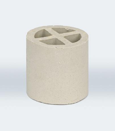
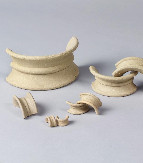
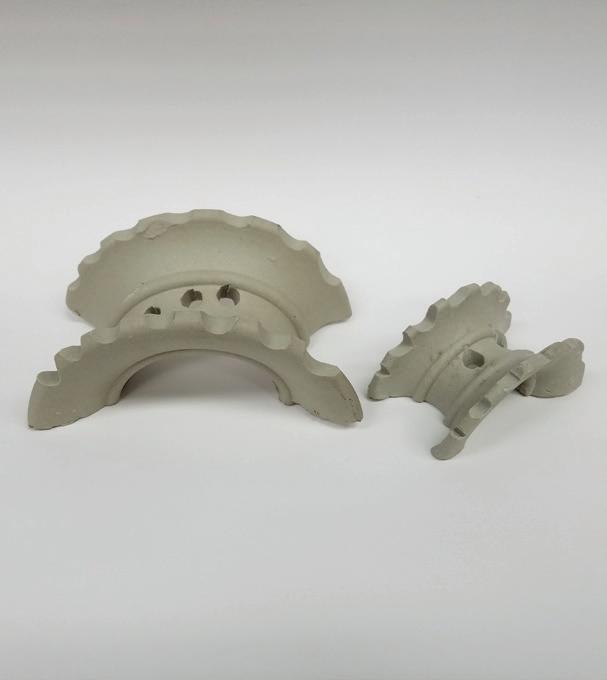
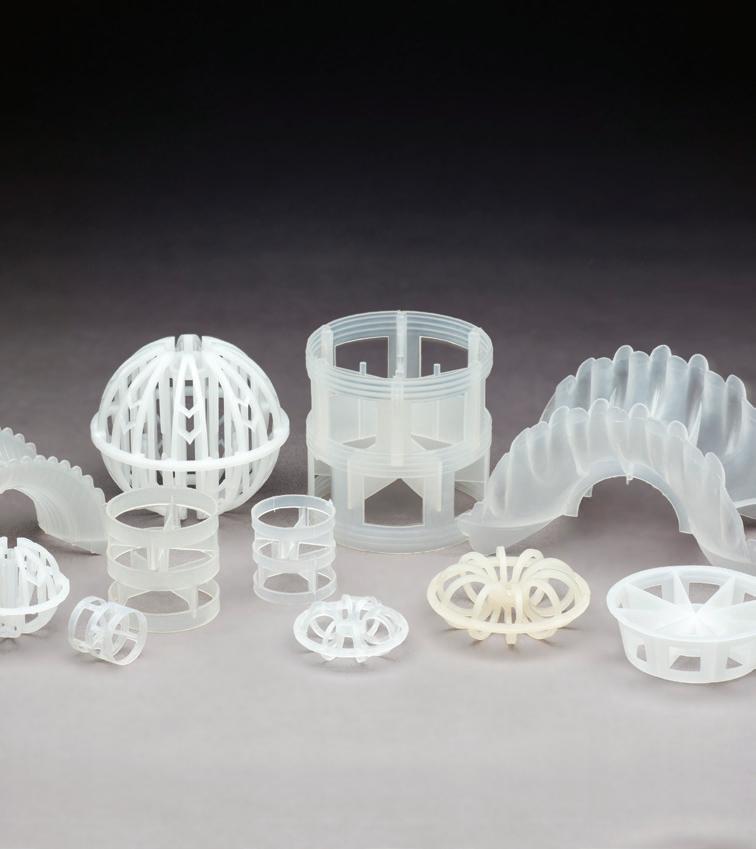
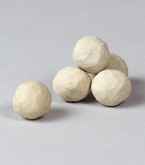

A World Leader in Catalyst Support Media and Tower Packing Plant Process Components Solutions For Your Sulfuric Acid Plant Christy Catalytics, LLC HOUSTON | SHANGHAI | DAMMAM | ROTTERDAM info@christyco.com www.christycatalytics.com LEARN MORE
EXPERIENCE SHIPPING TO OVER 75 COUNTRIES | 24/7 RESPONSIVENESS | FLEXIBLE | FULL STAFF OF TECHNICAL SUPPORT PERSONNEL Certified ISO 9001:2015
In-line dilution of sulfuric acid: CFD-supported analysis
By: Nelson Clark, Paulo Bautista, and Vitor Sturm, Clark Solutions
Dilution is a critical and worrisome operation in the sulfuric acid industry. After all, dilute sulfuric acid is extremely aggressive to a wide array of metallic materials. Not only that, but the dilution process is also strongly exothermic. Taking into consideration that corrosion rates increase exponentially with temperature, an incorrectly designed dilution system is a gateway to leaks and other process failures.
With that in mind, a plethora of different solutions already exist for sulfuric acid dilution in present day plants. One alternative is to use large acid tanks, due to long residence times and vast acid volume dissipating the brunt of the dilution process. Another is to take advantage of sulfuric acid at the bottom of absorption and drying towers to the same effect.
These solutions are well tested. However, if failure occurs in a large tank or acid tower, costs and downtime for repairs and replacements will be extremely significant. This article, therefore, aims to analyze another already existing option for plants: a simple in-line sulfuric acid dilution system.
To better understand the effect of some construction and process variables over the system, a computational fluid dynamics (CFD) approach was taken. Fluid flow, heat, and mass transfer were all simultaneously solved to give a deeper look at the dilution process. Our software of choice for this study was COMSOL Multiphysics™, based on the Finite Element Method.
Proposed system
The dilution of a drying tower bottom product was taken into consideration. Feed conditions are described in Table 1. Acid is fed into the system at 76°C and 98.2% strength. Process water at 40°C is mixed with the acid, resulting in a 97.2% product at 88°C on average. The dilution system consists of a 10” pipe through which acid flows at 2.0 m/s. Water is fed through 1.5” piping at 1.7 m/s. This system is based on real plant data. While these velocities may be on the higher end for cast iron applications, they are perfectly in accordance with our high silicon steel, CSX®, and its specifications.
CSX® is suitable for strong, not dilute, acid service. Therefore, a polymeric coating is necessary to protect the material from corrosion until acceptable levels are reached. The main quantitative metric used in this work, then, will be the minimum length of coating needed for the given application. Benchmark acceptable corrosion rate selected is 1 mpy.
Table 1: Feed conditions.
Table 3: Conditions for flowrate sensitivity study.
Premise
Due to superior representation of near-wall behavior, the k-w turbulence model was selected (Wilcox, 2006). KaysCrawford convective modelling was adopted for heat and mass transfer (Kays and Crawford, 1993). The simulation geometry adopted for the feed section is as shown in Fig. 1. Feed angle, number of water pipes and insertion of the water pipe inside the sulfuric acid system will be varied. The same can be said about the inlet flowrate of our sulfuric acid solution.
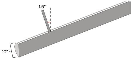
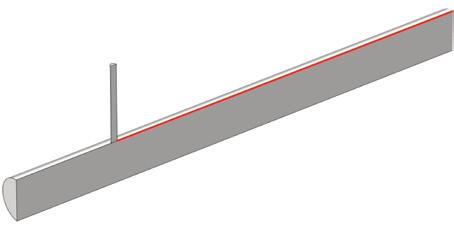
Sulfuric acid properties were taken from experimental results and in-company data. This is also the case for the isocorrosion diagrams of CSX and cast-iron. Also, regarding corrosion, the rates displayed were calculated for the wall region most
affected by dilution. See Fig. 2.
To better compare different results, a base scenario (“base”) was chosen. It consists of a single perpendicular water pipe, not inserted inside the dilution line.
Results for base scenario
Concentration and temperature profiles obtained from the simulation are described in Figures 3, 4, and 5.
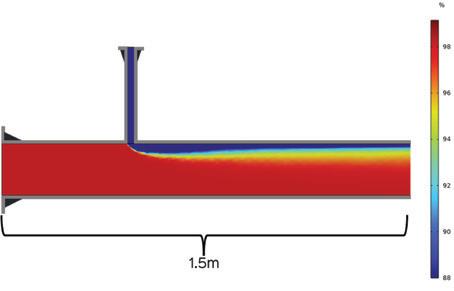
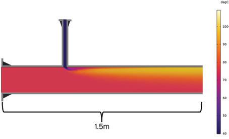
From the concentration profile, it appears that water does not penetrate far into the acid bulk. This is reasonable, taking into consideration the far greater momentum of the acid flow. Consequently, the dilution front is quite limited, with a strongly diluted pocket forming near the
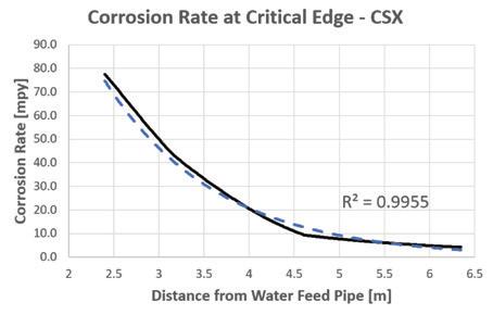
pipe wall and a relatively untouched acid bulk below.
From the temperature profile, we can clearly see the aggressive nature expected from sulfuric acid dilution. Temperature rises sharply from 40°C to more than 100°C in a few centimeters. It is not enough, however, to vaporize the solution. Furthermore, it is also notable that a hot region forms near the wall due to poor penetration in the acid bulk.
With the profiles shown in mind, the corrosion rates obtained along the critical edge are as shown in Fig. 5. The dashed line represents an exponential fit for our data on the continuous curve.
Sulfuric acid dilution is an extremely complex process, composed of many intertwined phenomena. “ ”
From the data, corrosion rates decay exponentially along the pipe due to acid concentration and heat dissipation. Accordingly, for a corrosion rate of 1 mpy maximum, the coating length needed is equal to 9.53m.
Effect of feed angle
Repeating the same simulations for different feed angles of 15° and 30°, the results shown in Table 2 were obtained. While there appears to be a reduction in coating length due to feed angles, there is a caveat. Computational fluid dynamics, as with any numerical model, has inherent uncertainties due to all the assumptions made and numerical errors that arise dur-
Boundary Diameter [in] Velocity [m/s] Temp [°C] Strength [wt] Acid Inlet 10 2.0 76 98.2% Water Inlet 1.5 1.7 40 -
Table 2: Coating length x feed angle.
Fig. 1: Dilution system feed.
Fig. 2: Critical edge for corrosion calculations.
Fig. 3: Base scenario concentration profile.
Fig. 4: Base scenario temperature profile.
Scenario Feed Velocity [m/s] Temp. Out [°C] Strength Out [wt] 120% Base 2.40 86 97.3% Base 2.00 88 97.2% 90% Base 1.80 89 97.0% 66% Base 1.67 94 96.7% 50% Base 1.00 99 96.2% Feed Angle Min. Coating Length [m] Percent Variation 0° 9.5315° 9.49 -0.4% 30° 9.12 -4.2% PAGE 34 Sulfuric Acid Today • Spring/Summer 2024 Feature
Fig. 5: Corrosion rate profile for base scenario.
ing calculations. Thus, small variations in numerical results, such as those presented, should be taken with a grain of salt.
Sensitivity to acid flowrate
This section aims to represent the effect of low acid load events on a dilution system. The following acid flowrate scenarios were created. Water flowrate was kept constant and equal to the base scenario. Expected outlet temperatures and concentrations were calculated from simple mass and energy balances. See Table 3.
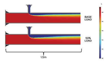
For a visual comparison, the acid concentration profile in the base and 50% base scenarios are presented later in this article. With a lower acid velocity, acid momentum is significantly reduced and water penetration increases. To quantify how much the flowrate affects system behavior, corrosion rates for each scenario were calculated at the same point. In that regard, we chose the point where the corrosion rate reaches 1 mpy for the base scenario, at 9.53m from the water feed.
In Fig. 7, it is clear that the acid flowrate affects the corrosion rate in an exponential fashion. Lower acid flowrates lead to a massive acceleration of corrosive action. Conversely, large acid flows lead to milder corrosion.
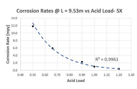
Effect of multiple water pipes
In an effort to better utilize the pipe volume for dilution, the next step is using multiple water feed pipes. After all, as seen in concentration profiles shown earlier, dilution is most intense near the water
Lower acid flowrates lead to a massive acceleration of corrosive action. Conversely, large acid flows lead to milder corrosion.
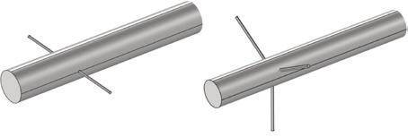
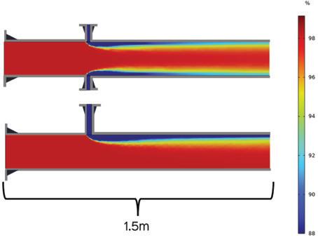
feed pipe due to low water penetration in the acid bulk.
The presence of more than one water feed pipe leads to better usage of acid available for dilution, as the concentration profile in Fig. 9 aptly shows.
In terms of coating, results are shown in Table 4.
While the three-pipe configuration leads to appreciable reductions, a system with three water pipes would have added complexity in terms of piping and space occupied. Therefore, the reduction in coat-

ing length may not compensate for other costs involved.
Effect of using pipe inserts
Another way to better utilize the acid volume and minimize coating needs is to use insertable water pipes, discharging dilution water directly into the acid bulk. As a result, the brunt of dilution occurs farther from the acid pipe wall, and therefore slower corrosion rates are to be expected. The concentration profiles shown in Fig. 10 illustrate this phenomenon.
A simple 1-inch insert already has a sensible effect on near-wall behavior, as the thin film of concentrated acid shows. Moreover, a 4-inch insert seems enough to completely damp any dilution effects on the wall. For quantitative results on potential CSX corrosion, refer to Table 5.
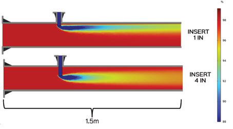
Despite seemingly not needing any kind of coating, the 4-inch insert analysis does not take plant events into account, such as flowrate variations or water pipe leaks. With that in mind, as a safeguard, it is still important to coat a small length of the pipe close to the water feed.
CSX ™ versus cast-iron
For a simple comparison, let’s take the 4-inch pipe insert configuration. CSX steel corrosion rates, in this scenario, were all below 1 mpy. Now taking a cast-iron pipe into consideration, the corrosion rate profile shown in Fig. 11 was observed.
Since our analysis does not account for events, an average yearly corrosion rate of 150 mpy will be assumed as reasonable
for the most aggressive regions in the pipe. With that value in mind, a cast-iron pipe would need to be replaced every one to two years since at least 50% of wall thickness is lost to corrosion. CSX, on the other hand, could last much longer if correct measures are taken, as corrosion rates are two orders of magnitude smaller on average for the same 4-in pipe insert scenario.
Conclusion
Sulfuric acid dilution is an extremely complex process, composed of many intertwined phenomena. Through computational fluid dynamics, the relevance of selected geometrical and process parameters was studied.
Water feed pipe angles do not have a strong effect on concentration and temperature profiles. Other geometric parameters, such as the depth of the water feed pipe, however, strongly influence nearwall behavior. Discharging water in the acid pipe bulk curbs the worst effects of dilution in the piping, leading to slow corrosion rates.
Increasing the number of water feed pipes implies better usage of the acid available for dilution. Consequently, the dilution process becomes faster and more well distributed through the acid volume. Even in optimal conditions, cast-iron pipes are not capable of withstanding the dilution process as well as CSX steel. In general, cast-iron piping would lose 50% of its wall thickness in one to two years even without extreme dilution events. On the other hand, CSX could last much longer if the proper measures are taken.
Overall, the system is also sensitive to process fluctuations. Corrosion rates soar as the acid flowrate decreases; with water rates kept constant. For this reason, it is good practice to partially coat the dilution pipe with PTFE even in optimal water feed configurations. q
References
WILCOX, D. C. Turbulence Modelling for CFD, 3rd ed. La Canada: DCW Industries, 2006.
KAYS, W.; CRAWFORD, M. Convective Heat and Mass Transfer. 3rd ed. New York: McGraw Hill, 1993.
Fig. 7: Variation of corrosion rate @ 9.53m with acid flowrate.
Fig. 8: Two- and three-water pipe geometries.
Fig. 9: Concentration profiles for different number of water pipes.
Fig. 10: Concentration profiles for different pipe inserts.
Fig. 11: Corrosion profile for a 4-inch castiron insert.
Fig. 6: Concentration profiles for different acid flowrates.
Table 4: Coating length for x number of water pipes.
No. of Water Pipes Min. Coating Length [m] Percent Variation One 9.53Two 3.97 -58% Three 3.15 -67% Pipe Insert Min. Coating Length [m] Percent Variation None 9.531 Inch 5.84 -39% 4 Inches 0.00 Minimum Length Sulfuric Acid Today • Spring/Summer 2024 PAGE 35 Feature
Table 5: Coating length for x pipe inserts.
“ ”
New Orleans, LA Faces & Places
Sulphur + Sulphuric Acid Conference


Kathy Hayward, right, of Sulfuric Acid Today enjoyed celebrating with sulfuric acid friends during a dinner held in conjunction with the conference. Pictured, on left, are Jack Harris of VIP International, Howard Tenney of Tenney Co., Rob Schlege of Ecoservices, Ricky Jaswal of Weir Lewis Pumps, and Marwan Karaki of Weir Lewis Pumps. At right are Hayward, Gavin Floyd of Ecoservices, Stan Miller of VIP International, and Hoss Maddry of VIP International.


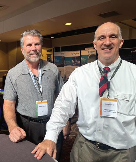
During a conference reception, Steve Puricelli of EXP, left, visits with Jim Dougherty of Elessent MECS Technologies.

in the

Presenting at the Sulphur + Sulphuric Acid Conference, Gavin Floyd of Ecoservices explains the recent Quench tower project at the Dominquez California plant site.


Taking a break from the conference to enjoy a New Orleans dinner are, on left side, Jack Harris of VIP International, Marcelo Kascheres of Elessent MECS Technologies, Tom Dormenval of Rio Tinto Kennecott, Stan Miller of VIP International, and Hoss Maddry of VIP International. Pictured at right are Kai MacMurray of Rio Tinto Kennecott, Alan Sandoval of Rio Tinto, Frank Asirifi of Rio Tinto Kennecott, and John Horne of Elessent MECS Technologies.

Luis Ganes of Sauereisen shares his company’s diverse line of corrosion-resistant materials with conference attendees.


Roland Guenther of Steuler-KCH presented a case study regarding the replacement of the upper part of a co-current flow Quench tower.

of
with an attendee at their exhibition during the conference.
Members
Begg Cousland Envirotec Ltd, Martyn Dean, left, and Mhairi Murphy converse
Visiting during a reception are, from left, Thomas Burke of Elessent MECS Technologies, Vulcan Mutler of EXP, Howard Tenney of Tenney Co., and Doug Azwell of Elessent MECS Technologies.
Catching up during the conference in New Orleans are, from left, Reed Bond of JR Simplot, Stuart Hinze of JR Simplot, Hanno Hintze of Aurubis AG, Andreas Kraxner of CS Combustion Solutions, and Marie Vognsen of Topsoe.
Visiting
exhibition area are, from left, Greg Zhayko of Border Chemical, Chase Geddes of Itafos, Patrick Polk of Topsoe, Demian Guthmiller of Itafos, and Dennis Smerchanski of Border Chemical.
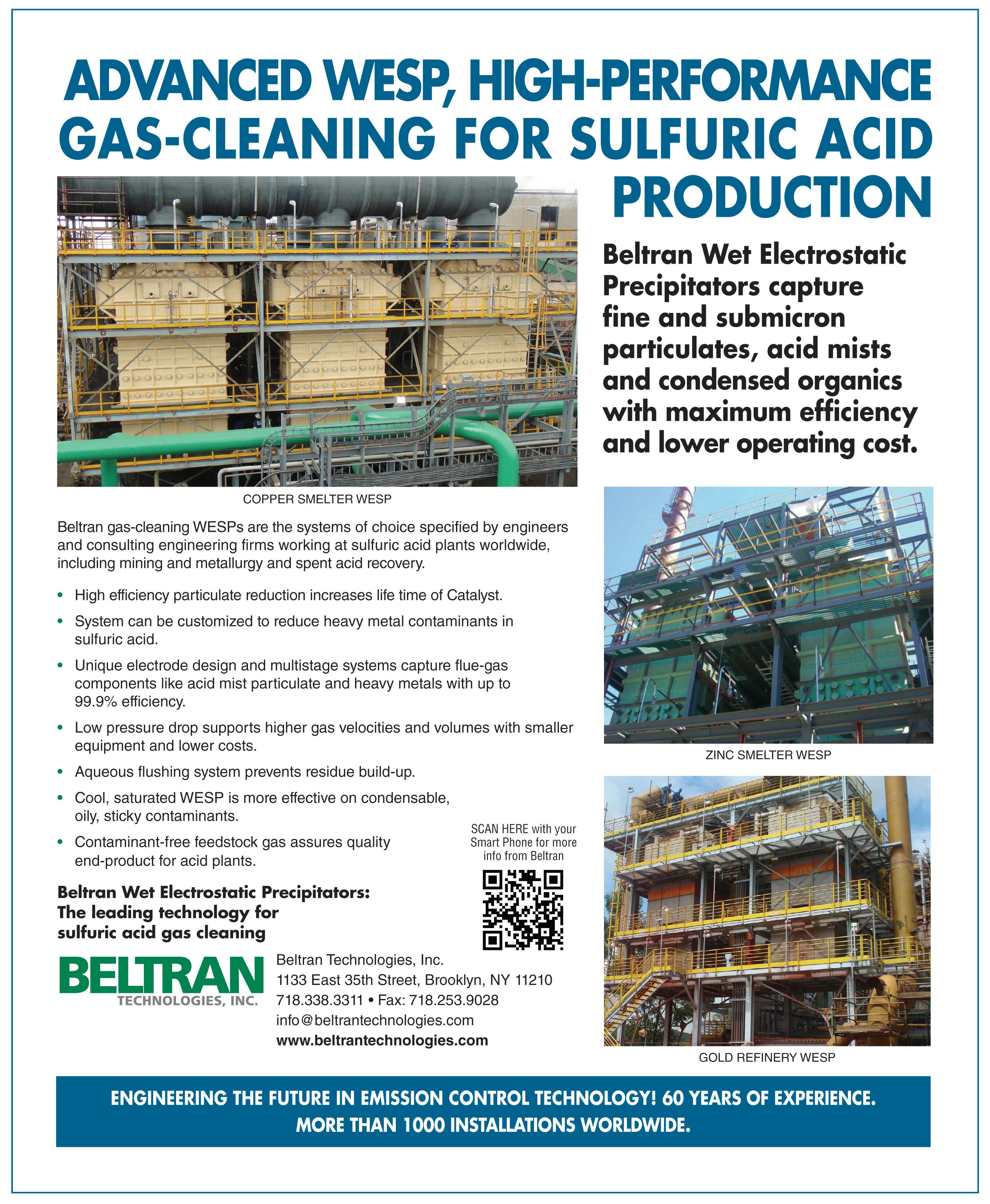
Annual fertilizer & sulfuric acid technology convention to meet in Florida
CLEARWATER, Florida–Each year for the last 46 years, members of the AIChE Central Florida Section and colleagues from all over the world have gathered at Clearwater Beach to share their ideas concerning chemical process technology, specifically the production of phosphoric acid, phosphate fertilizers, and sulfuric acid. The AIChE Fertilizer & Sulfuric Acid Technology conference provides ample excuse for a relaxing getaway with friends and family, good food, and a lot of fun.
This year, the 47th convention will be held at the Sheraton Sand Key Resort in Clearwater on Friday, June 7th and Saturday, June 8th.
The conference will have a Sulfuric Acid Workshop and other various topics including the bi-annual PE laws, rules, and ethics workshop. Delegates can also earn up to 8 PDH for attending both Friday and Saturday sessions. To obtain PDH certifi-
cation for conference sessions, participants must attend the full session of the section for which credit is needed. Delegates must also supply their P.E. number on or before Friday, June 7th, 2024 and have attendance verified by proctors.
For more information regarding the convention, please visit the event’s website: www.aiche-cf.org or contact Convention Chair Edin Veladic at vicechair@aichecf.org or Section Chair Robert Andrew at chair@aiche-cf.org.
XIV Round Table of Sulfuric Acid Plants to gather in Chile
PUERTO VARAS, Chile–Holtec’s Round Table for 2024, XIV Round Table for Sulfuric Acid Plants, will take place September 1-5 at the Hotel Dreams in Puerto Varas, Chile.
Plant operators and maintenance experts, technology providers, consultants and specialized engineering firms will discuss the latest developments in markets,
technology, projects, operations, and the environment.
Delegates from many countries in Central and South America will participate, as usual, but attendees from Africa, Asia, Europe, and North America will also present their projects and discuss operational and maintenance topics during the four-day seminar.
Meanwhile, technology providers will have a unique opportunity to talk directly with customers and present their new products, technologies, and developments.
For more information, visit the event’s website: mesaredondachile.com.
Sulphur + Sulphuric Acid 2024 slated for Spain
LONDON–The Sulphur + Sulphuric Acid conference continues to be an essential annual forum for the global sulfur and acid community to learn, connect, and do business. Knowledge sharing is at the event’s core via the respected dual-streamed technical program and the connections made
among the industry experts and solution providers attending.
The conference will take place November 4-6 at the Hyatt Regency in Barcelona, Spain.
In 2024, attendees can expect an expanded market outlook agenda with expert insights from CRU’s analysis teams on major supply and demand markets, including sulfur and sulfuric acid, plus additional industry updates from key players across the supply chain.
Covering technical updates on the production and processing of sulfur and sulfuric acid, the event will feature industry-leading presentations covering new innovations in process, technology, materials, and equipment developments, as well as practical case studies highlighting operational experience and improvements.
Running alongside the agenda will be an exhibition of world-class solution providers serving the sulfur and sulfuric acid industries.
For more information, please visit the event’s website: www.crugroup.com q


CALENDAR OF EVENTS PAGE 38 Sulfuric Acid Today • Spring/Summer 2024 Department
THE ART OF ACID PROOFING

SOUTHWEST REFRACTORY DELIVERS THE HIGHEST QUALITY ACID PROOFING, REFRACTORY, INDUSTRIAL MASONRY AND FIREPROOFING WORK.
With in-depth engineering support, meticulous craftsmanship and extensive planning down to the finest details, we’re turning industry into artistry.
VIEW OUR GALLERY OF ACID PROOFING AND OTHER REFRACTORY PROJECTS AT SWRREFRACTORY.COM.
(281) 824 9342 INFO@SWR-US.COM


 Operators preparing to start up the new plant.
New cooling tower and package boiler.


 INTEREP crews working on two tied universal expansion joints, installed due to the tight space constant created by the elbows seen at the top of the photo.


 Guy Cooper, Director, Marketing and Sales, EXP


