CONCRETE FUTURES
Research Seminar TU/e
1st Quartile 2020
From Mould Making to 3D Concrete Printing

Advanced tools of manufacturing, computational design and digital fabrication strategies have radically transformed both architecture and construction industry. This seminar will explore emerging developments in these fields, all in relation to concrete. A traditional building material, concrete is being transformed by an increasingly wide palette of digital fabrication tools. The way we unify as designers the logic of computation with material logic, tool properties, process logic of manufacturing and assembly is key to developing intelligent and sustainable concrete structures and ultimately architectures.
We take a close look at the evolution of technologies — from analogue to digital — revolving around concrete constructions. We will explore the relationship between geometry, fabrication technique and advanced digital tools of making. Through the identification and analysis of relevant case studies, from practice and research, our students determine and systematise different strategies of analogue, digital and hybrid approaches to building with concrete. A special focus is placed on mould making and 3DCP, making use of the large scale 3D concrete printer at the TU/e and the existing knowledge base. The analysis allows for an understanding of the interdependencies between material, tool, geometry and computation from which then the manufacturing logic derives. By evaluating the case studies, an overview of the current state of art will be gained, advantages and disadvantages are identified, future potentials recognised.
CONCRETE SHELL

HEINZ ISLER, 1954 - 2008
SWITZERLAND
Reinforced concrete shells are by far the most noticeable part of a building envelope. They dominate the architectural expression, yet the three-dimensional shape is normally decided by the engineer according to its structural quality, rather than by the architect according to esthetic considerations. (Chu-Chun Chuang, 2017).
Heinz Isler, the Swiss engineer, is considered to be the last of the great 20th century shell builders. He is characterized by the fact that his shells were built over a span of more than 50 years, from the first one in 1954 to 2008. While much of it was built in his native Switzerland, there are examples in southern Germany, France , the UK, and even Saudi Arabia as well. He is best known for his groundbreaking methods of form-finding by thin membrane extension, inflation and hanging.– which resulted in shells such as the Wyss Garden Centre, Solothurn (J.C Chilton, 2011).
Concrete shell roof of the garden center Wyss in Zuchwil, (Chriusha, 2009)Design Strategy and Form Generation
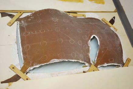
For form-finding of his shells Isler loaded the fabric surface with a plaster of his own formula developed to maximize moldability when wet whilst maintaining a constant thickness on the curved fabric and minimizing cracking of the drying surface. However, Isler also realized the shortcomings of this technique, due to the influence of fabric weave and its orientation relative to the boundaries. To minimize these effects, for more accurate modelling of the hanging surface, Isler employed a selected high quality latex rubber membrane which has consistent isotropic properties (J Chilton, 2012).

It is interesting to note that Isler also seems to have experimented with a mechanical method of form finding. The assembly consisted of a wooden frame from which was suspended a triangular piece of latex rubber, similar in form to Isler’s Deitingen Süd motorway service station shells. As noted previously, for any given plan shape, the number of forms that can be found using a hanging membrane is potentially infinite (J Chilton, 2012). Hence Isler depended on the following factors for forming his shell’s shape:
• Shaping
• Artistic
• Expression
• Statics
• Construction
• Cost
A further consideration is buckling of the shell under compression stresses, particularly at the free edges and where loads concentrate near the supports. From the series of models Isler was able to assess the appearance of each in terms of the aesthetics, approximate compression stresses within the surface and approximate buckling resistance (J Chilton, 2012).
Development models of both built and unbuilt projects, (John Chilton, 2010) Experimental model on rectangular grid fabric, (Chu-Chun Chuang, 2016).Large-scale epoxy resin model for detailed assessment of buckling resistance of the surface (John Chilton, 2012).
Material and Material Strategy
Owing to the thickness of the shell surface, all major aspects of the on-site design had to be carried out very carefully. In the development process, three major factors led Isler’s shells to a good result. The materials for the formwork were chosen so that the high strength of the concrete could be conveniently shaped in all directions. Some temporary works, including scaffolding, which was normally used to sustain the load of up to 300 kg / m2 of the total structure, were necessary despite the quality of building material and on-site techniques. In a parallel array, Glulam timber beams were applied to support transverse laths of timber. Until adding concrete to the floor, insulation was then used as left-in-place shapework. To ensure its good quality, all the details were planned prudently in advance. (CHUANG, C, 2016)
Tools of Making and Fabication Strategy
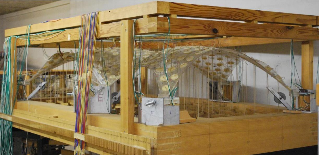
For the development of its designs, Heinz Isler relies on the optimised behavior of the membrane principle of thin shells. The use of physical simulations is the basis of this ‘optimized structure’ design technique. The flexible membrane is automatically simulated initially on the horizontal plane surface, with any shape and boundary conditions, and capable of bearing many defined loads (Vizotto,I,2010).
The surface is deformed under the influence of these loads before one of its equilibrium configurations, which determines the middle surface of the shell to be constructed, is achieved. According to the principle of minimum total potential energy, the location of the membrane ‘s steady equilibrium correlates to the local minimum points of the total potential energy function. (Vizotto,I,2010).
 Latex rubber form-finding model for the Sicli SA factory shell in Geneva, (John Chilton, 2012).
LITERATURE REFERENCES
Chilton, J. (2011, September). 50 Years of “New Shapes for Shells”. Retrieved from https://www.researchgate.net/ publication/321309670_Heinz_Isler_-_50_Years_of_New_ Shapes_for_Shells_Preface_by_Guest_Editors
John Chilton Chuang2, C. (2017, November 01). Rooted in Nature: Aesthetics, Geometry and Structure in the Shells of Heinz Isler. Retrieved in October 22, 2020, from https://link.springer.com/article/10.1007/s00004-0170357-5
Vizotto,I.(2010,December).Computationalgenerationof free-form shells in architectural design and civil engineering. Retrieved from https://www.sciencedirect.com/science/article/pii/S0926580510001330?via%3Dihub
CHUANG, C., & CHILTON, J. (2016, September). DesignandModellingofHeinzIsler’sSicliShell.Retrieved from https://nottingham-repository.worktribe.com/OutputFile/801802
Chilton, J. (2012). Form-finding and fabric forming in the work of Heinz Isler. Retrieved from http://www.fabwiki. fabric-formedconcrete.com/lib/exe/fetch.php?media=nottingham:form-finding_and_fabric_forming_in_the_work_ of_heinz_isler.pdf
FABRIC FORMWOK MIGUEL FISAC, 1973 - 1975
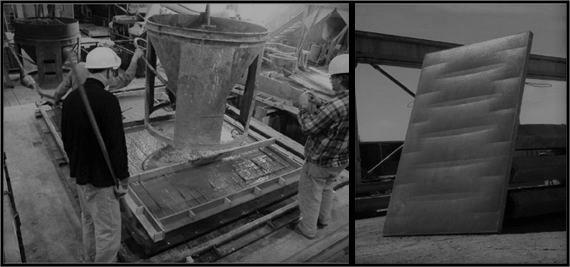
Miguel Fisac is the most significant and internationally best known architect of those who made the modern renovation of Spanish architecture in the second half of the 20th century. Fisac’s work affects all the main or tangential fields of architecture, so that it covers both buildings and urban planning, the creation of furniture and objects, industrial design or painting. He used fabric-formed panels in many of his projects in Spain, employing smooth polyethylene sheets hanging from a rigid frame as formwork for precast façade panels and his work is based on the fabric formwork (fundacionfisac, n.d).
Fabric formwork is a building technology that involves the use of structural membranes as the main facing material for concrete moulds. Unlike traditional formwork, the material is highly flexible and can deflect under the pressure of fresh concrete. The resulting forms exhibit curvature as well as excellent surface finishes that are generally not associated with concrete structures. It uses simple timber frames and flat sheets of untailored fabric to create columns, walls, beams and shells based on the advantages of being flexible deformed. Furthermore, tailored moulds add a further dimension to the possibilities of fabric formwork (Diederik Veenendaal, 2011).
 MADRID, SPAIN
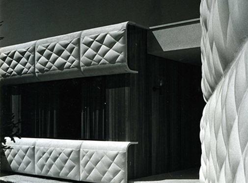
Facade detail 2, (Studio Miguel Fisac, 1973)
MADRID, SPAIN
Facade detail 2, (Studio Miguel Fisac, 1973)
Design Strategy and Form Generation
Fisac projected the plan of the house following irregular lines that respected two beautiful holm oaks. From an entrance hall there is access to a large common space, without any compartmentalization but organized by the gentle inflection of the façade. It consists of a living room, and an area with a fireplace to talk and listen to music, with views to the south. The intimacy of the family office and bedrooms is achieved through a covered patio. In addition, fisac’s concepts for prefabrication in building projects, using flexibly formed façade panels that are cast horizontally and lifted into position as the structural element in prefabricated sandwich walls (Hawkins, 2016).

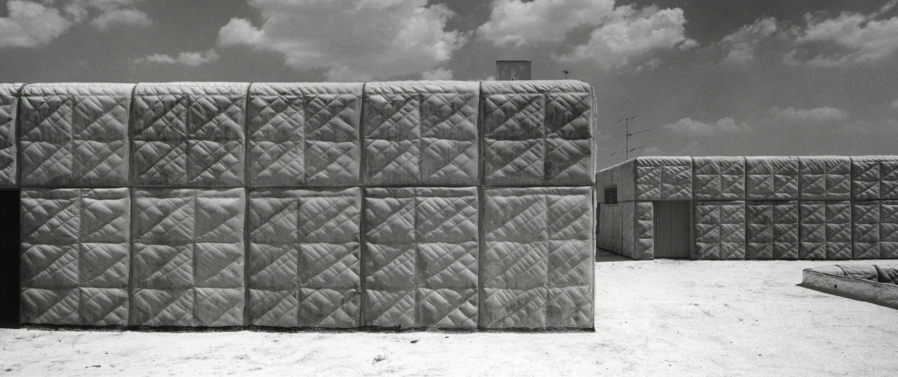
MUPAG rehabilitation center 2 (Foundation Miguel Fisac, n.d.)
MUPAG rehabilitation center (Foundation Miguel Fisac, n.d.)
Studying the pressure of liquid concrete at the base of the fabric formwork, (Remo F Pedreschi, 2015)

Material and Material Strategy
The basement is formed by means of air chambers, whereas the rest of the villa was constructed with metal posts and brick bearing walls. The roof consists of a reinforced concrete framework. The most outstanding feature of the villa is the outer coating of white concrete elements which are prefabricated in special forms. These elements are joined to neoprene sections so as to fasten the window glass without carpentry (Fisac Serna, 1973).
In addition, tFisac developed one of his inventions regarding the castable qualities of concrete to encircle all these spaces. White concrete was poured into flexible plastic molds to provide the qualities of the paste and the weight of the concrete, leaving its tactile appearance soft and spongy. These concrete panels were also devised to hold the double glazing of the windows fixed with neoprene profiles, sealing against air noise (arnardóttir, n.d).
Tools of Making and Fabication Strategy
Fabric formwork systems present the possibility of manufacturing concrete in various types of structures. To create the façade structure of the Juan Zurita residence, the fabric formwork was based on his work and his work used smooth and flexible polyethylene sheets hanging from a rigid structure as a formwork. Each side of the façade building is not uniform, but it shows the result of the façade texture in a unified layout. In addition, the façade of his other buildings also use a fabric formwork system, and the more flexible formwork is used to create a more curved shape. In this process, cables and cable nets offer more possibilities of controlling their shape while being combined with the fabric (Hawkins, 2016).
Full-scale formwork and completed concrete panel, (Robert P. Schmitz, n.d).
LITERATURE REFERENCES
Veenendaal,D.,West,M.,&Block,P.(2011).History and overview of fabric formwork. Retrieved from https:// block.arch.ethz.ch/brg/files/suco_201100014.pdf
Cionfisac, F. (n.d.). Extracto. Retrieved October 22, 2020, from http://fundacionfisac.com/miguel-fisac/biografia/extracto/
Hawkins, W., Herrmann, M., Ibell, T., Kromoser, B., Michaelski,A.,Orr,J.,Pedreschi,R.,Pronk,A.D.C., Schipper, R., Shepherd, P., Veenendaal, D., Wansdronk, R., &West,M.(2016).Flexibleformworktechnologies: astateoftheartreview.StructuralConcrete,17(6),911–935 .https://doi.org/10.1002/suco.201600117
Fisac Serna, M. (1973). Casa Pascual de Juan Zurita. Retrieved October 22, 2020, from https://elarafritzenwalden. tumblr.com/post/156007083948/casa-pascual-de-juan-zurita-la-moraleja-madrid/embed
Arnardóttir, H. (n.d.). Casa en La Moraleja de Madrid, de Miguel Fisac. Retrieved October 22, 2020, from http://historiasdecasas.blogspot.com/2006/05/casa-en-la-moralejade-madrid-por.html
Hawkins, W., & Herrmann, M. (2016, December). Flexible formwork technologies: A state of the art review. Retrieved from https://pure.tue.nl/ws/portalfiles/portal/55007059/suco201600117_Hawkins.pdf
KNITCANDELA
ZAHA HADID, 2018 - 2019
MAXICO
Zaha Hadid, in full Dame Zaha Hadid, (born October 31, 1950, Baghdad, Iraq—died March 31, 2016, Miami, Florida, U.S.), Iraqi-born British architect known for her radical deconstructivist designs. In 2004 she became the first woman to be awarded the Pritzker Architecture Prize (Zukowsky, 2004).
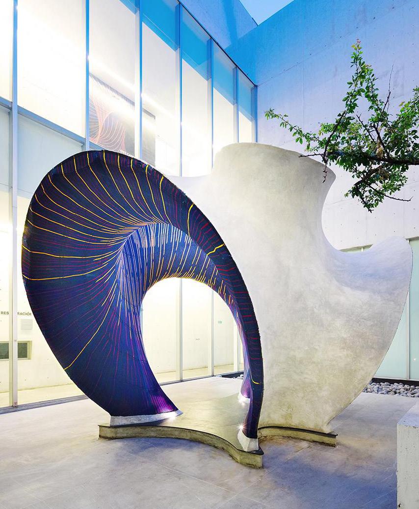
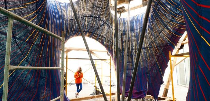
KnitCandela is a thin, wavey, 50 m2 concrete waffle shell built at the Museo Universitario Arte Contemporáneo (MUAC) in Mexico Cityas part of the first exhibition of Zaha Hadid Architects in Latin America In the fall of 2018. The 5 tonnes concrete shell was built using a 55 kg,flexible cable-net and knitted-fabric formwork tensioned into a timberland steel scaffolding frame. The design was developed by the BlockResearch Group at ETH Zurich in collaboration with the ComputationalDesign Group of Zaha Hadid Architects (ZHCODE). Designed as a ho-mage to the Spanish-Mexican shell builder Félix Candela (1910–1997), (Popescu, 2020).
Design Strategy and Form Generation
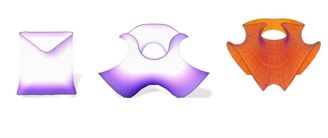
The form finding of the KnitCrete formwork (the cable-net and knitted shuttering) and thus of the resulting shell was done using compas_fofin, the force density-based form-finding package (Van Mele 2019).
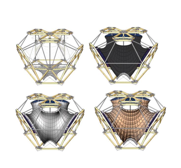
A target geometry for the form-finding process was defined through a series of design iterations with the goal of balancing the aesthetical and structural targets of the project. To keep the detailing of KnitCrete formwork clean and simple, the topology of the cable net follows a quad pattern, with closed continuous ring cables in the “horizontal” direction, and boundary-to-boundary cables in the opposite, “vertical” direction. The horizontal cables were used for generating prestress and the vertical cables to transfer the loads from boundary to boundary of the supporting structure, (Popescu, 2020).
Although the cable net was modelled with discrete cable segments rather than continuous horizontal and vertical cables, the force densities were controlled cable per cable, rather than segment per segment to obtain a smooth naturally curving geometry. The form finding was done while taking into account the weight of the resulting shell surface. Since each change in force density results in a new shell geometry, which in turn has a new weight, this is an iterative process, (Popescu, 2020).
Form generation steps,(designboom, 2020)
Installation steps,(designboom, 2020)
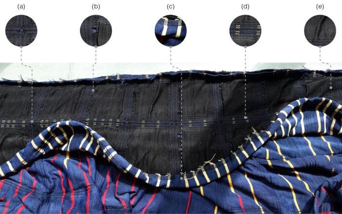
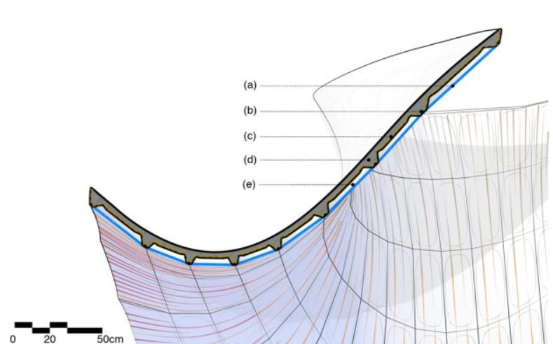
Detail section, (a) two-layered knitted textile; (b) cable net; (c) fast-setting cement-paste coating; (d) concrete waffle shell; and (e) voids, (Popescu, 2020).
Material and Material Strategy
From what is mentioned before, KnitCandela was built up out of two parts, The framework which was made essentially from wooden panels, steel joints, steel wires,fast hardening cement, and textiel which is taking a part in the coating as well. The other part, which is the coating, it consists mainly of poured concrete. It starts by installing the wooden framework in place, after that, setting up the steel wires, and then hanging the textile. As a last step using the cement coat and pouring the concrete.
Tools of Making and Fabication Strategy
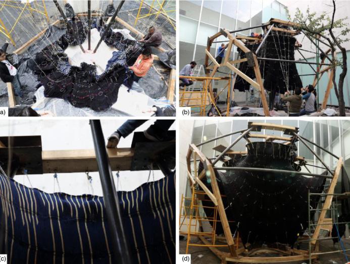
The concrete shell was constructed on site over a period of four weeks. First, the timber and steel frame was assembled and fitted with all of the hooks for hanging and tensioning the cable-net and knitted textile formwork . All of the cables were cut to the predefined length and laid out onto plotted drawings with each node intersection marked along the length of the cable, (Popescu, 2020).
Double-sided textile with included features: (a) openings for connecting the cables of the cable net; (b) openings for inserting balloons; (c) textile border for joining pieces together; (d) channels for cables; and (e) variable loop, (Maria Verhulst, n.d).
These cables were inserted into the knitted textile shuttering and fitted with turnbuckles at the ends. This package was then attached to the supporting frame and taut into shape using the turnbuckles. Once tensioned, balloons were inserted into the textile’s pockets, to create the waffle shell’s weight-saving cavities, as described previously. The entire textile was sprayed with a cement-paste coating for stiffening , and then, concrete was applied manually onto the formwork . Finally, once the concrete had hardened, the cables were released and the frame removed, (Popescu, 2020).
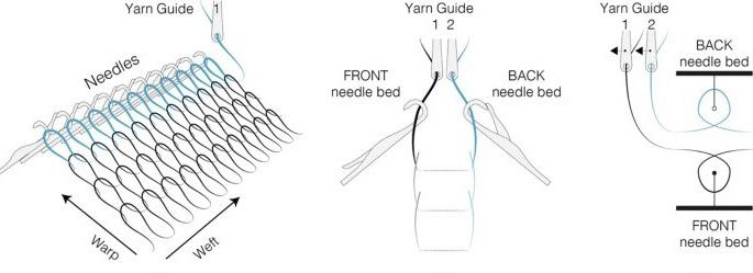
Machine needle bed layout, (Popescu, 2020).
Tensioned cable-net and knitted textile formwork and the minimal scaffolding needed, (Verhulst, 2020).
Physical-Digital Fabrication Strategy
The KnitCandela, incorporated the hybrid design strategy which also represents an evolution of the flexible forming system. Using computational means of designing the form, to be then used with 3D printing, a major part of the framework (The textiel), the other part was manually installed (the wood panels and steel wires). As for the coating it was completely manual work, (Michael Walther, 2018). The implementation of this strategy went as the following,, an industrial knitting machine produced the shuttering of the formwork for the shell structure: in 36 hours, it knitted a fully shaped, double-layered 3D textile consisting of four long strips The lower layer forms the visible ceiling – a designed surface with a colourful pattern. The upper layer contains sleeves for the cables of the formwork system and pockets for simple balloons, which, after the entire structure is coated in concrete, become hollow spaces that help save on materials and on weight. Manufacturing a formwork for such a geometrically complex structure using conventional methods would cost substantially more in both time and material, (Walther, 2018).
Advantages, Potential and Challenges
Hoisting and tensioning of the hybrid cable-net and knitted textile formwork in the timber frame: (a) cable-net and textile formwork placed around centre supports of tensioning frame with ropes tied to nodes, (b) hoisted formwork fixed to the top of the tensioning frame, (c) connection between cables and frame and (d) formwork connected to all the frame hooks, (Verhulst, 2020).
The KnitCandela prototype demonstrated that knitted textiles can be used to shape complex geometries at the architectural scale. This encourages the use of lighter materials and a reduction of the amount of material used for building structures, reducing the structural volume of a construction material. The latter is especially important for concrete, which is the most widespread building material in global use.Lightweight fabric formwork systems offer an alternative to traditional construction formwork systems. By using a flexible membrane instead of a rigid formwork, textiles have proven to be a feasible solution for the creation of lightweight, waste-reducing formworks for a wide variety of complex building components. Moreover, because of their compactness and light weight, they can be effortlessly transported to the construction site, (Popescu, 2020).
LITERATURE REFERENCES
Zukowsky, J. (2004). Zaha Hadid. Retrieved October 22, 2020, from https://www.britannica.com/biography/Zaha-Hadid
Popescu, M., Rippmann, M., Liew, A., Reiter, L., Flatt, R., Mele, T., & Block, P. (2020, March 03). Structural design, digital fabrication and construction of the cable-net and knitted formwork of the KnitCandela concrete shell. Retrieved October 23, 2020, from https://www.sciencedirect.com/science/article/pii/S2352012420300655
Walther, M. (2018, October). 3D-knitted shells save on construction materials and time. Retrieved October 23, 2020, from https://ethz.ch/en/news-and-events/eth-news/ news/2018/10/knitted-concrete.html
CONFLUENCE PARK MATSYS DESIGN, 2018 - 2019
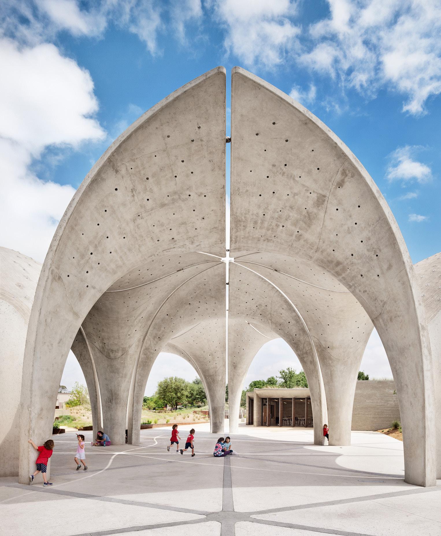
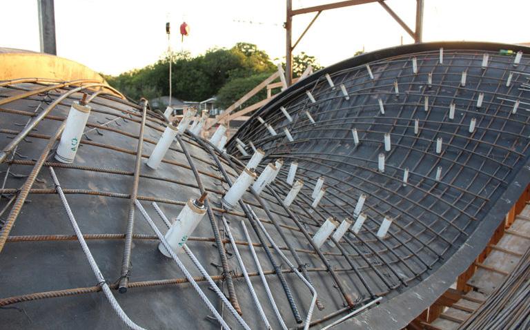
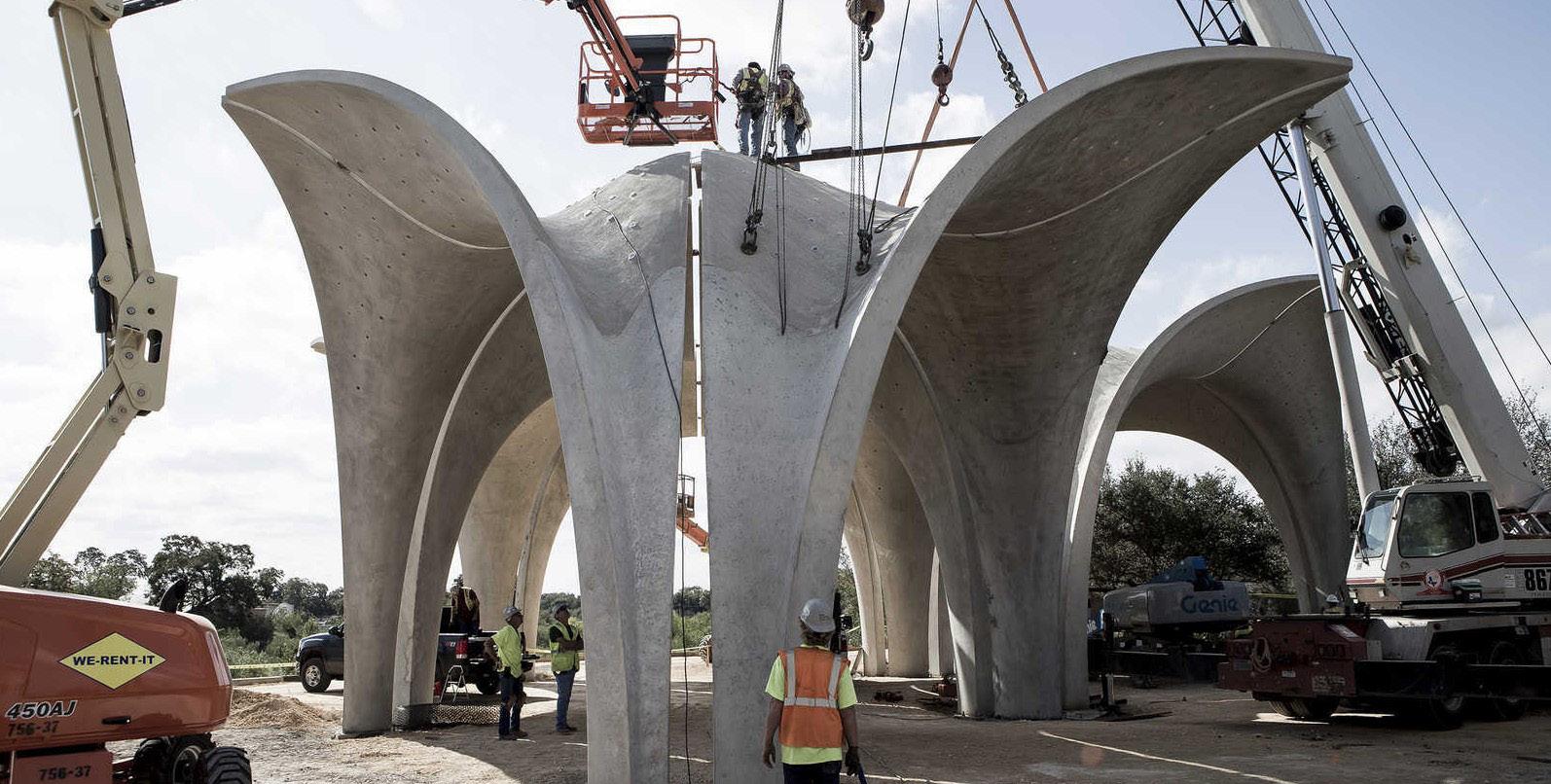
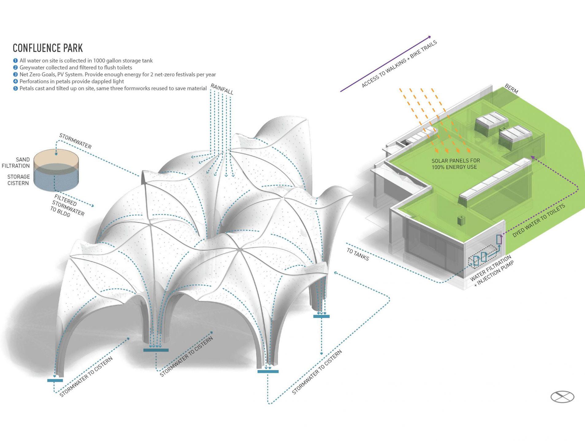
Located along the Mission Reach section of San Antonio River, Confluence Park is an educational park focused on the important role of water in the local ecosystem. In collaboration with Lake|Flato Architects, Rialto Studio and Architectural Engineering Collaborative, the Matsys-designed this Park and it is composed of 3.5 acres of native planting, 2000 square foot of multi-purpose buildings, a 6,000 square foot of central pavilion, and three smaller “satellites” pavilions scattered throughout the park. The central pavilion consists of 22 concrete “petals” that organize a network of vaults that provide shade and direct the flow of rainwater into an underground cistern used for park`s irrigation. The pavilion’s design was motivated by the way many plants in the region direct rainwater to their root system, utilizing the structural efficiency of the curved surface. Each petal was cast on site using a modified tilt-up construction technique and digitally fabricated fiberglass composite molds and then lifted into place in pairs to form structural arches. The pavilion represents our deep interest in the integration of form, fabrication, and performance, (matsys, 2018).
 SAN ANTONIO, TEXAS
Design Strategy and Form Generation
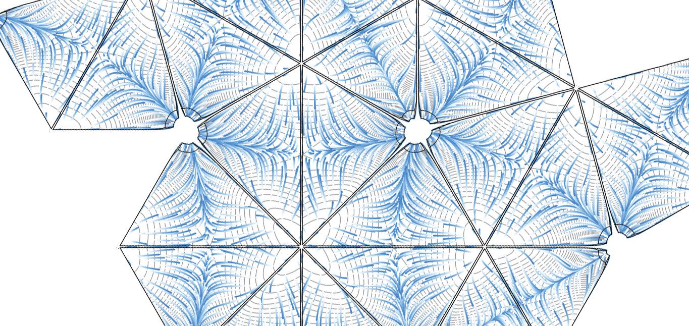
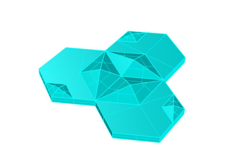
The pavilion geometry is inspired by some plants’ use of doubly curved fronds to cantilever out and collect rainwater and dew and redirect the water towards its root stem. A modular system of concrete “petals” was developed that collected rainwater and funneled it to the petals’ columnar bases and then on to a central underground cistern. One of the key concerns when developing these petals was to make sure it looked modular but not repetitive, (matsys, 2018).
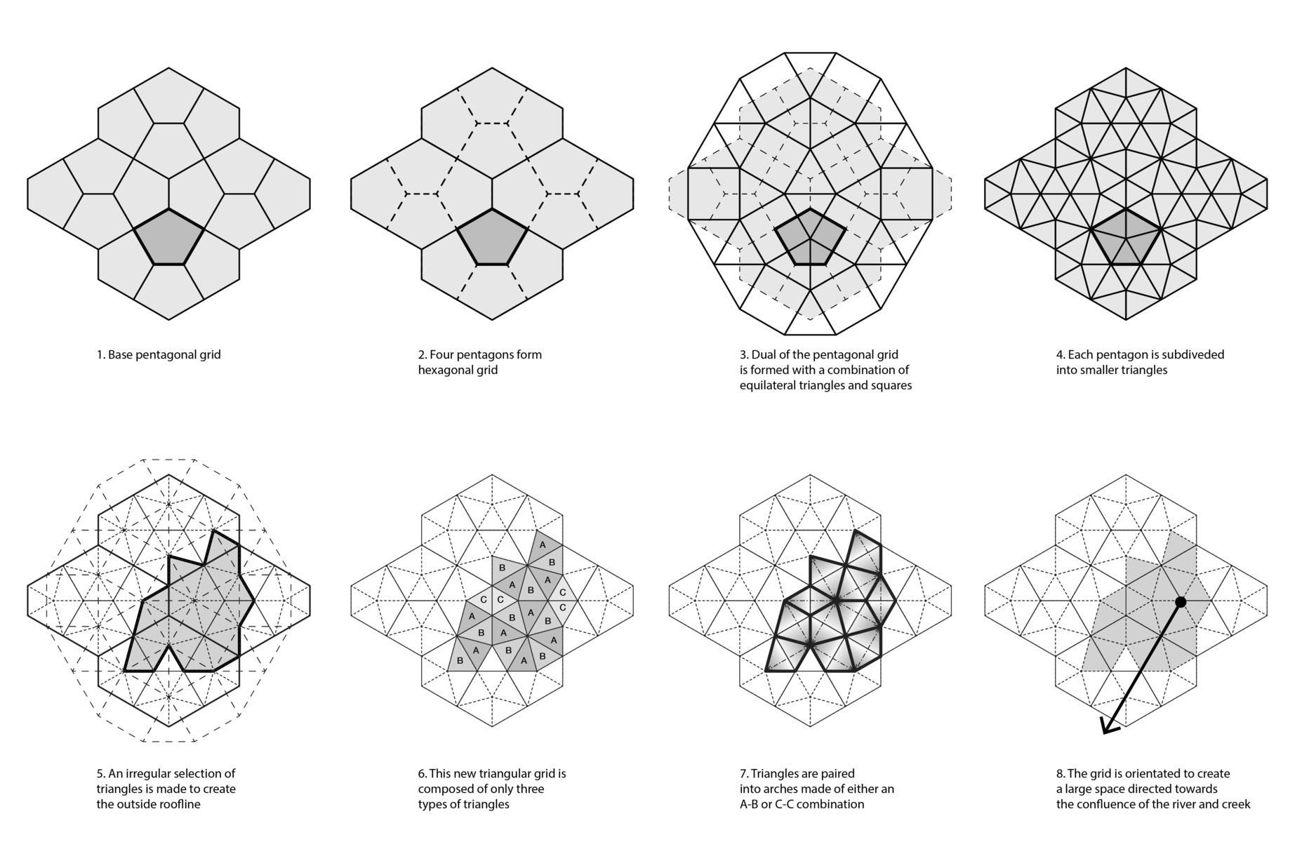
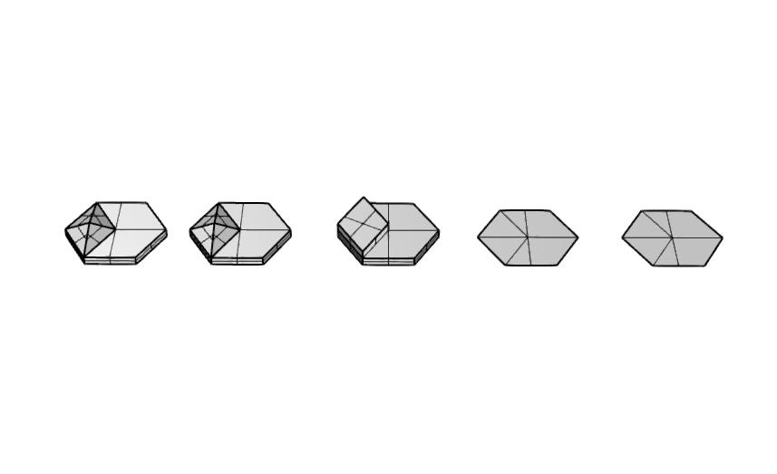
The design uses an irregular pentagon, Cairo tile, as the base grid to address the tension between cost-effective modularity and the desire for spatial abundance. The pentagon is subdivided into five triangles in a way that only creates three unique modules: two asymmetric triangles mirrored each other and one equilateral triangle. From this irregular triangular base grid, a parametric model was used to create the three-dimensional solids of each petal. Structurally, each petal is half of an arch which starts out as a 16” thick column and tapers to a 4” deep curved roof. The double-curvature of the surface geometry helps with the structural rigidity of the petal. Each petal is connected to its paired half-arch by two structural pin joints. The petals’ capacity to shed water in the proper direction was tested through water flow analysis using particle simulations, (matsys, 2018).
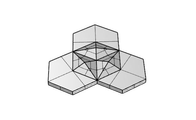
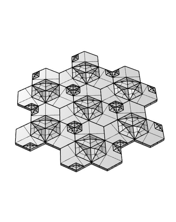
Concrete paver pattern diagram (Matsys, n.d.)
Concrete paver pattern diagram (Matsys, n.d.)

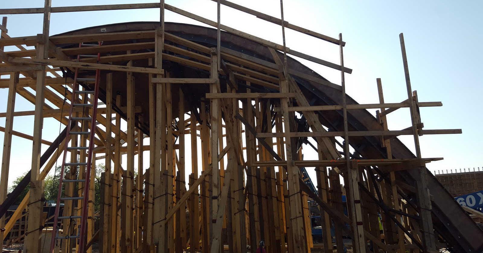
Installing the framework on site (Casey Dunn, n.d)
Material and Material Strategy
The center of the park is the main pavilion, consisting of 22 concrete “petals” that form huge archways and these petals were also used to construct the smaller pavilions, organizing a network of vaults. To make these structures, the special technology was important for the development of concrete in the park. Given the relevant structural gymnastics, the project’s structural engineer, the Architectural Engineers Collaborative (AEC), was also an essential part of the design team. During the design process, all petals of steel, cloth and wood were considered, but concrete was ultimately chosen for durability and permanence, (Hightower,2018).
Tools of Making and Fabication Strategy
The design required only three unique petal shapes even though the apparent complexity of the assembled petals. The three petal’s formwork was fabricated off of 5-axis CNC milled forms. After milling the foam forms, a 2” thick composite structure composed of inner and outer layers of fiberglass composite with a central core of balsa wood was applied. Especially for the fiberglass formwork, It was tried to high-density foam molds to make the shape of the crucial geometry. After that, the fiberglass and balsa were then cast against these patterns to create the final molds were then reinforced with a steel truss substructure which would facilitate the transport and on-site assembly of the molds, (Melby, n.d).
Showing the wooden support under the structure,(Casey Dunn, n.d)
Final step of attaching the structures to each other,(Casey Dunn, n.d)
How does Conflunce park serve as an irrigation system itself, (Matsys,
Physical-Digital Fabrication Strategy
The main design in this project is the three forms of unique petal. It was modified digitally using Grasshopper and Rhino and the resulting computer files were used by a 5-axis CNC router at their factory in California. The mold was then shipped to the site and placed in a way that could be cast into a modified tilt-up wall construction. This avoided the need for a fully enclosed form which decreased the cost and allowed the top and bottom surfaces to have radically different finishes: the bottom is cast against the smooth fiberglass while the top is broom-finished with the broom strokes aligning with the direction of the water flow, (Matsys,2020).
After arriving at site, a false work was constructed using a shoring system to support the fiberglass molds at about 45 degrees in order to achieve proper consolidation and finishing of both column and petal segments in a monolithic way. The reinforcement then was formed and installed in place on each placement of the molds which had three separate and different sizes, (Melby, n.d).
Advantages, Potential and Challenges
Confluence park is not only the structure responsible for the irrigation system itself, but also presents the possibility of providing educational functions to people. For instance, the development of the central government center focused on creating a space of inspiration and aspiration that helped deliver the client’s mission to provide environmental education on water conservation. In addition to showing the potential for modern concrete construction, Confluence park demonstrate possibility to make something unique design when a highly collaborative interdisciplinary design team works with an educated client. This great precedent provides an opportunity to impart specific functions to concrete structures that will be built in the future, which can also be an opportunity to create another unique design result, (Hightower,2018).
Water flow diagram (Matsys, n.d.) n.d.)Matsys. (2018). Confluence Park. Retrieved October 23, 2020,fromhttps://www.matsys.design/confluence-park
Hightower,B.(2018,August15).SculpturalconcretecanopiescoolaSanAntoniopublicpark.RetrievedOctober23, 2020, from https://www.archpaper.com/2018/07/lakeflato-sculptural-concrete-cools-san-antonio-confluence-park/
Melby,B.(n.d.).ConfluenceParkRiverPavilion.Retrieved October 23, 2020, from https://tilt-up.org/projects/profile/?id=5712
LITERATURE REFERENCES
From ancient civilizations to the present day, columns have served as architectural elements, especially tied to the harmony, balance, and proportion of architectural orders. Nowadays the columns have begun to identify as works of art on their own. These columns created in this way meet digital technologies to create more diverse types of structures, (Dbt,2020).
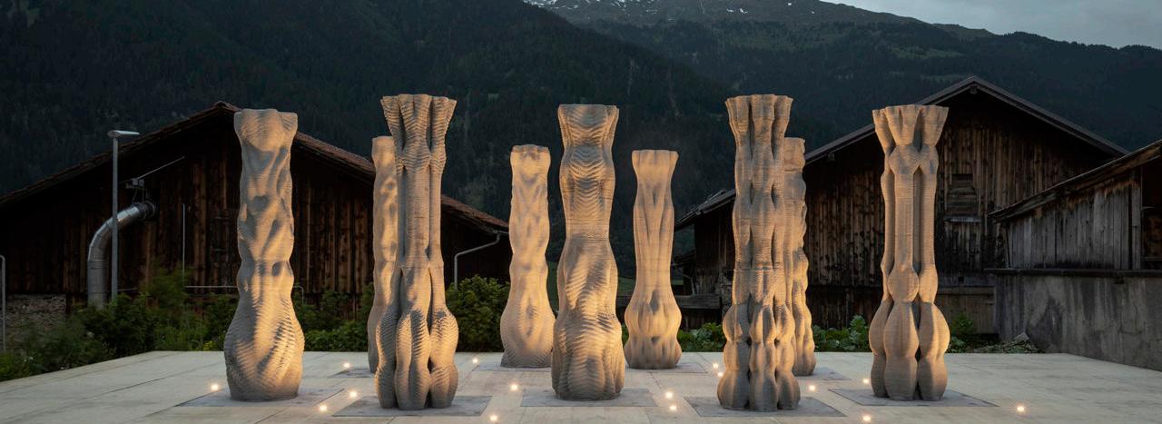
In collaboration with the Origen Festival in Riom, Switzerland the installation Concrete Choreography consists of nine, individually designed, 2.7m tall columns. Students of the Master of Advanced Studies in Digital Fabrication and Architecture explore the unique possibilities of layered extrusion printing, demonstrating the potential of computational design and digital fabrication for future concrete construction. In addition, hollow concrete structures are printed in a strategically usable way only if necessary, allowing a more sustainable approach to concrete architecture. The nine columns will function as the backdrop for the festival’s various dance shows in the 2019 summer season in Riom – it is easy to imagine how the artists will sneak in, grab hold of and dance around them. They also show how 3D technologies can bring new representations to architecture; this is a major advantage that many manufacturers have already put their trust in, (Anton, 2020).
 CONCRETE CHOREOGRAPHY, MAS DFAB, 2019 RIOM, SWITZERLAND
Design Strategy and Form Generation
Two procedural computational design engines based on trigonometric functions and mesh segmentation were developed and utilized in the design process. Each column was designed as a double shell composition with structural internal bracing. The outer shell dimensions ranged from 250 to 600mm with a highly differentiated decorative exterior, and the inner shell that housed the existing reinforced concrete cavity was maintained as rationally as possible to enhance stability. Within each layer, these shells were connected by minimal print-paths. As a result, this internal bracing provided structural support for adjacent shell layers of newly printed material and increased the achievable overhang for the column geometry, as well as providing a closed core for partial concrete casting, (MASETHDFAB,2018).
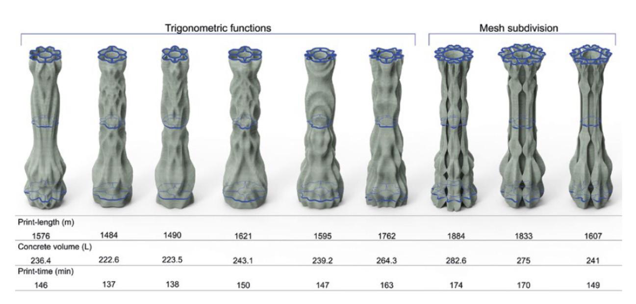
 Fabrication metrics for the columns (MAS DFAB, n.d.)
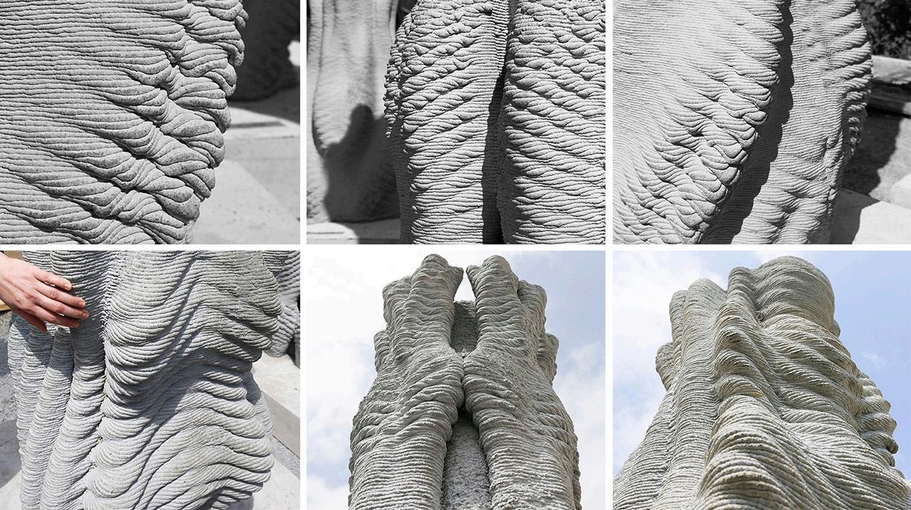
Detail of material ornament (Sofia Michopoulou, n.d.)
Fabrication metrics for the columns (MAS DFAB, n.d.)
Detail of material ornament (Sofia Michopoulou, n.d.)
Material and Material Strategy
A key goal was to provide precise print resolution as a result of high production speed, process stability and robustness. For that reason, the new material used in this project and the specific fast-setting 3DCP process using a new yield stress mortar developed at ETHZ exceeds the limits of conventional prefabrication of structural elements. Another objective was to investigate the extrusion layer as a design tool for high-resolution and multi-scalar material articulation. The column typology met the geometric criteria to test the rapid, vertical build-up rate of the fabrication method, demonstrating the targeted qualities according to the critical element heights. It also provided the opportunity to evaluate the robustness of the recently developed 3DCP prefabricated platform. The issue was to find out whether new general representation and quality of the material could be produced by directly 3D printing exposed concrete elements without the demand of post-processing, (Anton, 2020).
Tools of Making and Fabication Strategy
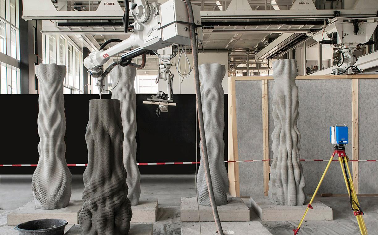
All columns were entirely prefabricated at the Robotic Fabrication Lab (RFL) of the ETHZ, using one ABB IRB 4600 industrial robot mounted on a Güdel three-axis gantry system. The print-tool was mounted at a 45° orientation on the sixth robot axis to reach the component height without changing the robot working configuration during printing. In this setting, the robot could print multiple 3.2-metre-high artefacts, aligned on the gantry`s Y-axis. Production was executed in automatic mode to ensure safety at the required print speed. In automatic mode, a laser-fence tied the production area apart from the material handling and control areas, (Anton, 2020).
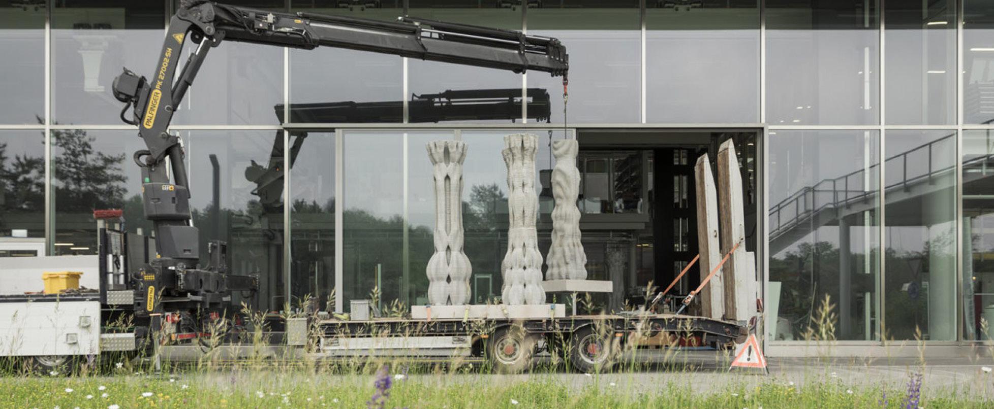 Transportation (Benjamin Hofer, n.d.)
Night view (Benjamin Hofer, n.d.)
Fabrication set up (Axel Crettenand, n.d.)
Transportation (Benjamin Hofer, n.d.)
Night view (Benjamin Hofer, n.d.)
Fabrication set up (Axel Crettenand, n.d.)
Physical-Digital Fabrication Strategy

Computationally designed material decoration and surface textures show the diversity and important aesthetic potential that 3D concrete printing can hold when used in largescale structures. This fact is shown in nine columns made through 3D concrete printing, all of which have different designs and one-of-a-kind designs with complex geometries can be manufactured in a fully automated way once the design of the 3D model is completed. It took about 2.5 hours to print each column with complex shapes and precise details. Their work expanded to the internal structure of the columns that required the addition of strength to the minimum material, (Carlota,2019).
Advantages, Potential and Challenges
To decrease the ecological footprint of concrete, digital fabrication seeks to reduce the amount of concrete used and to remove the additional work sequences or unnecessary materials used in temporary scaffolds and formworks. This essentially limits the design space by challenging the rationalisation and serialisation dogmas, which are key to economic motivation to reuse the formwork, (Aouf, 2019). As can be observed in concrete choreography with these efforts, 3DCP provides an opportunity to construct lean structural elements by placing concrete only where necessary. Combining the ecological advantages of waste-free with shape customization of digitization, mould-less shaping of concrete shifts the focus of concrete research from formwork production to controlling the properties of fresh paste during its transition to cured concrete. Therefore, the shift from mold-based indirect manufacturing to direct manufacturing of 3D printed parts causes a rapid paradigm shift in concrete technology, (Anton, 2020).
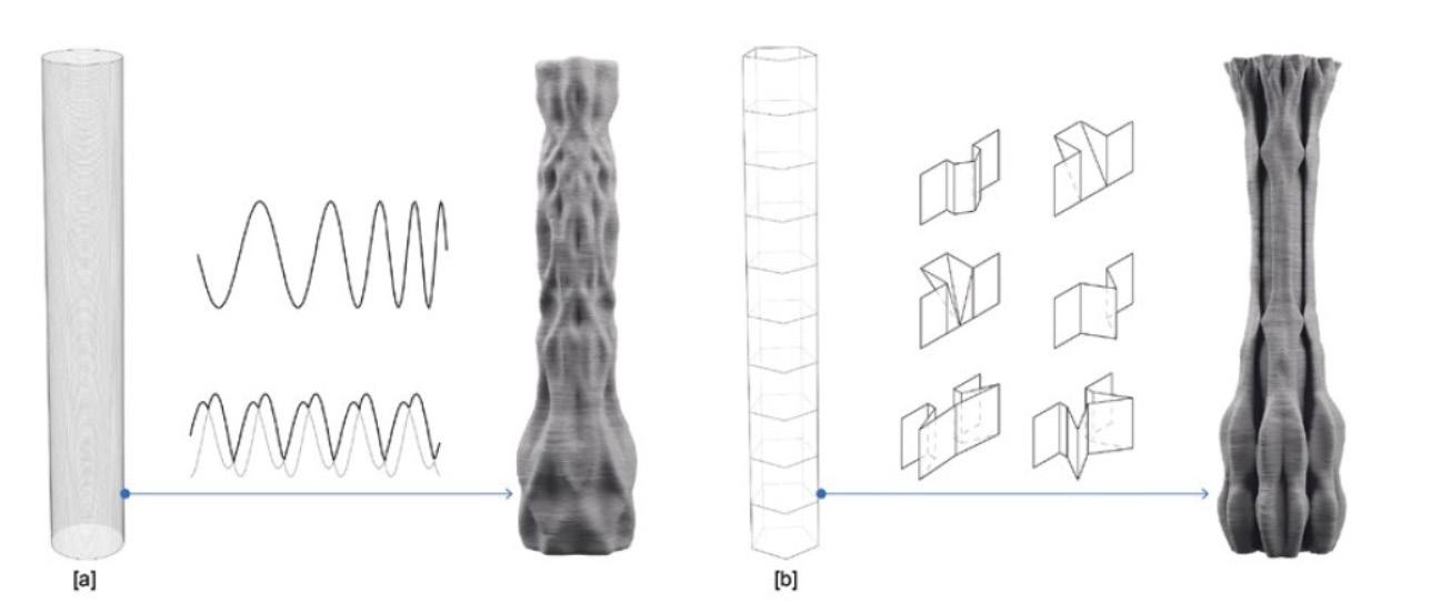 Design engines (MAS DFAB, n.d.)
Digital fabrication (Patrick Bedarf, n.d.)
Design engines (MAS DFAB, n.d.)
Digital fabrication (Patrick Bedarf, n.d.)
LITERATURE REFERENCES
Dbt. (2020, March 02). Concrete Choreography. Retrieved October 23, 2020, from https://dbt.arch.ethz.ch/project/ concrete-choreography/
Anton, A. (2020). Concrete Choreography: Prefabrication of 3D-Printed Columns. Retrieved from https://www.researchgate.net/publication/340547596_Concrete_Choreography_Prefabrication_of_3D-Printed_Columns
MAS ETH DFAB. (2018). Concrete Choreography. Retrieved October 23, 2020, from https://www. masdfab.com/work-1819-concretechoreography?fbclid=IwAR3ZGqw6Z7DvpiHvnQAltJTU6EkVfH5nY9D2pmBRvCISI06FLgnT2QmKzZ
Carlota, V. (2019, July 25). Concrete Choreography are 9 unique 3D printed columns. Retrieved October 23, 2020, from https://www.3dnatives.com/en/3d-printed-columns-260720195/
Aouf, R. (2019, July 24). Students’ 3D-printed Concrete Choreography pillars provide a stage for dancers. Retrieved October 23, 2020, from https://www.dezeen. com/2019/07/24/3d-printed-concrete-choreography-pillars-design/
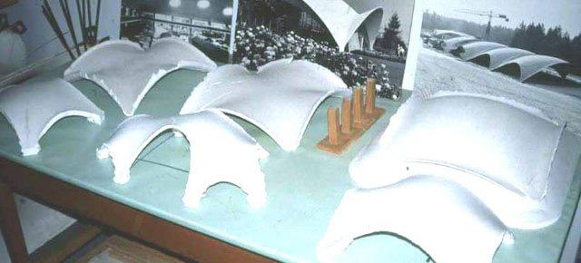
 Experiment 1.
Experiment 4.
Experiment 2.
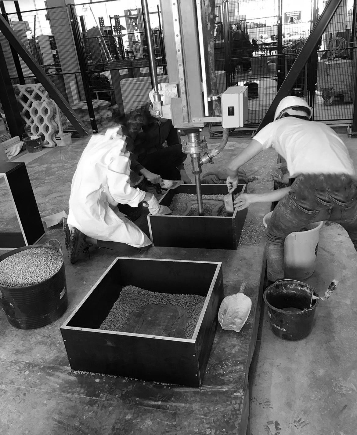
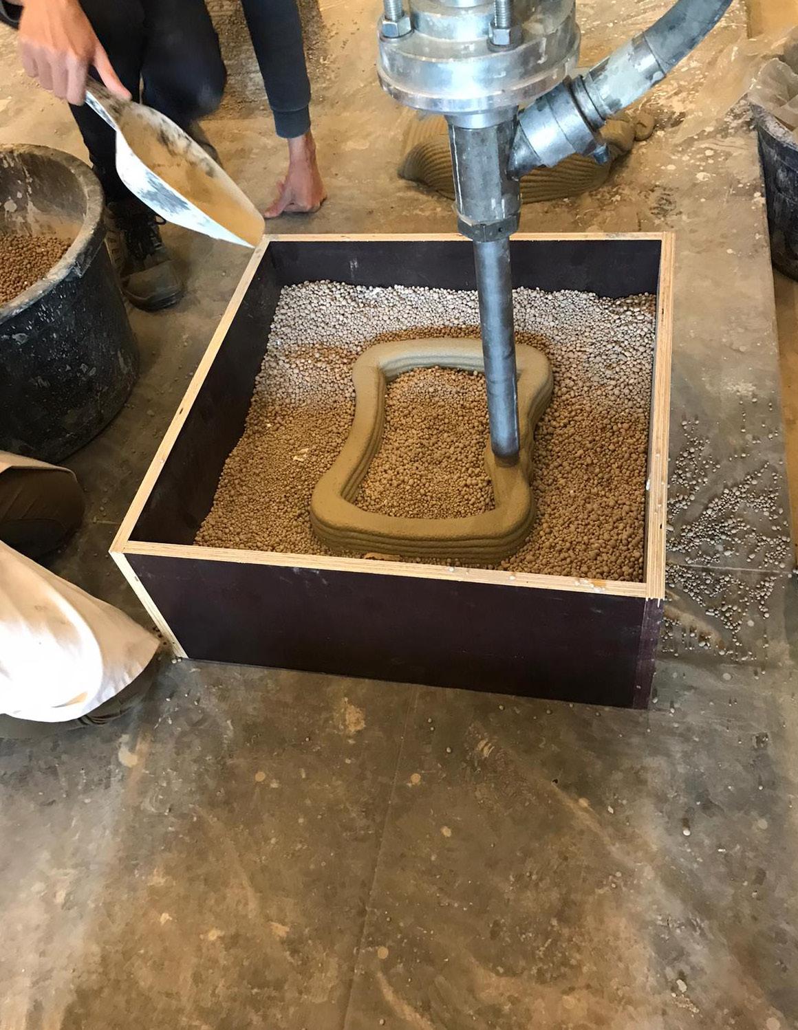
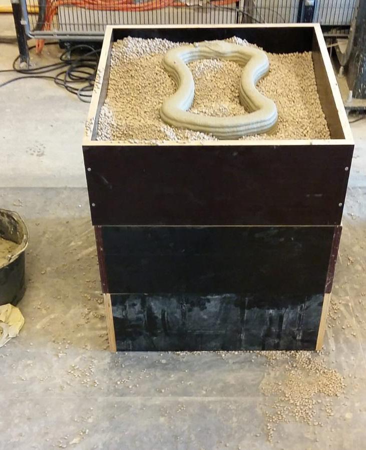
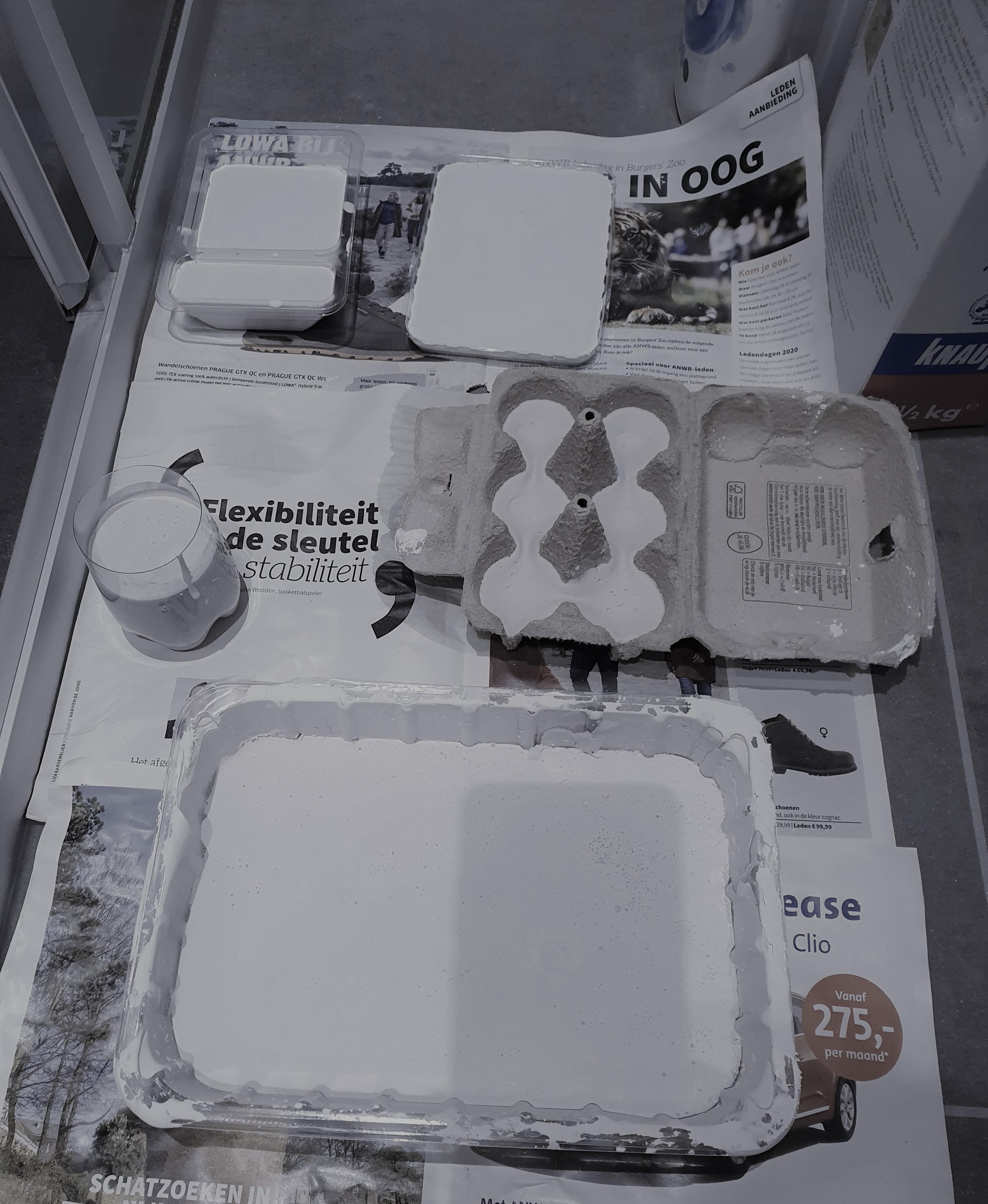
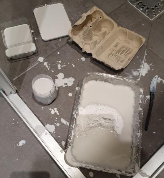
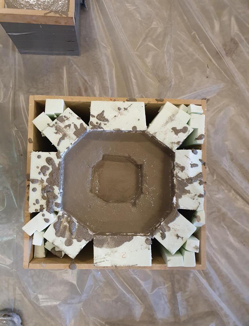
The pouring process.
Experiment 5.
Experiment 3.
Experiment 1.
Experiment 4.
Experiment 2.
The pouring process.
Experiment 5.
Experiment 3.
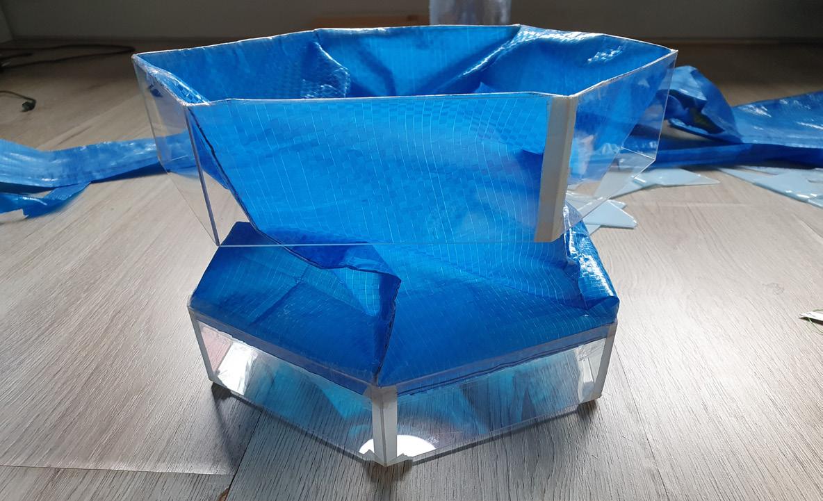
 Sealing the surrounding.
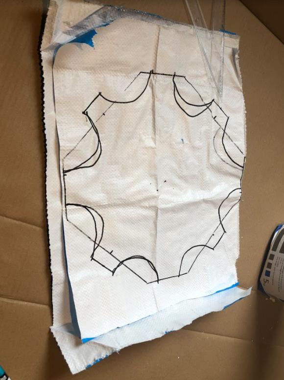
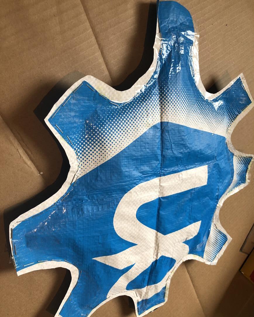
Sketching the outer shape on plastic bag.
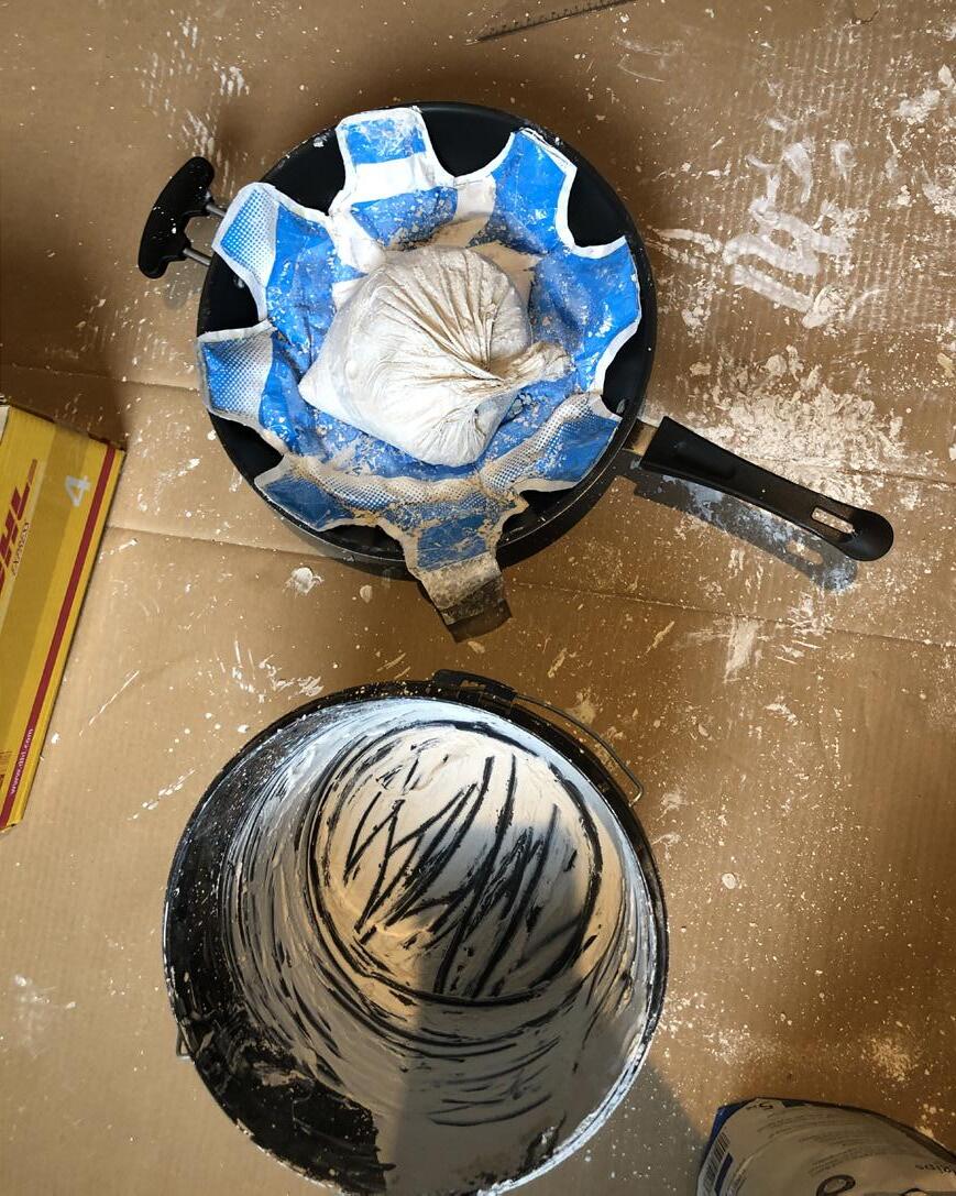
Forming the shell shape by using cooking pan.
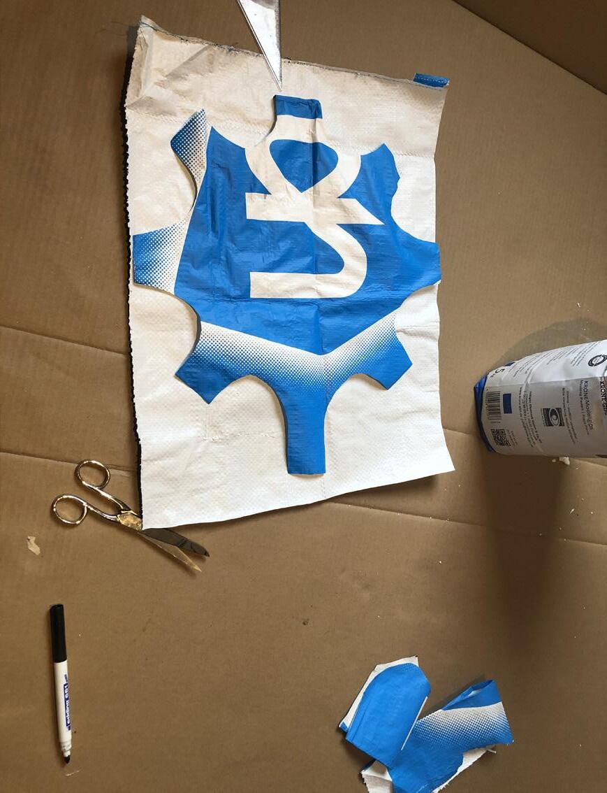
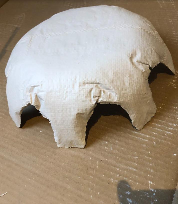
Ading another layer to form the mold.
Sealing the surrounding.
Sketching the outer shape on plastic bag.
Forming the shell shape by using cooking pan.
Ading another layer to form the mold.
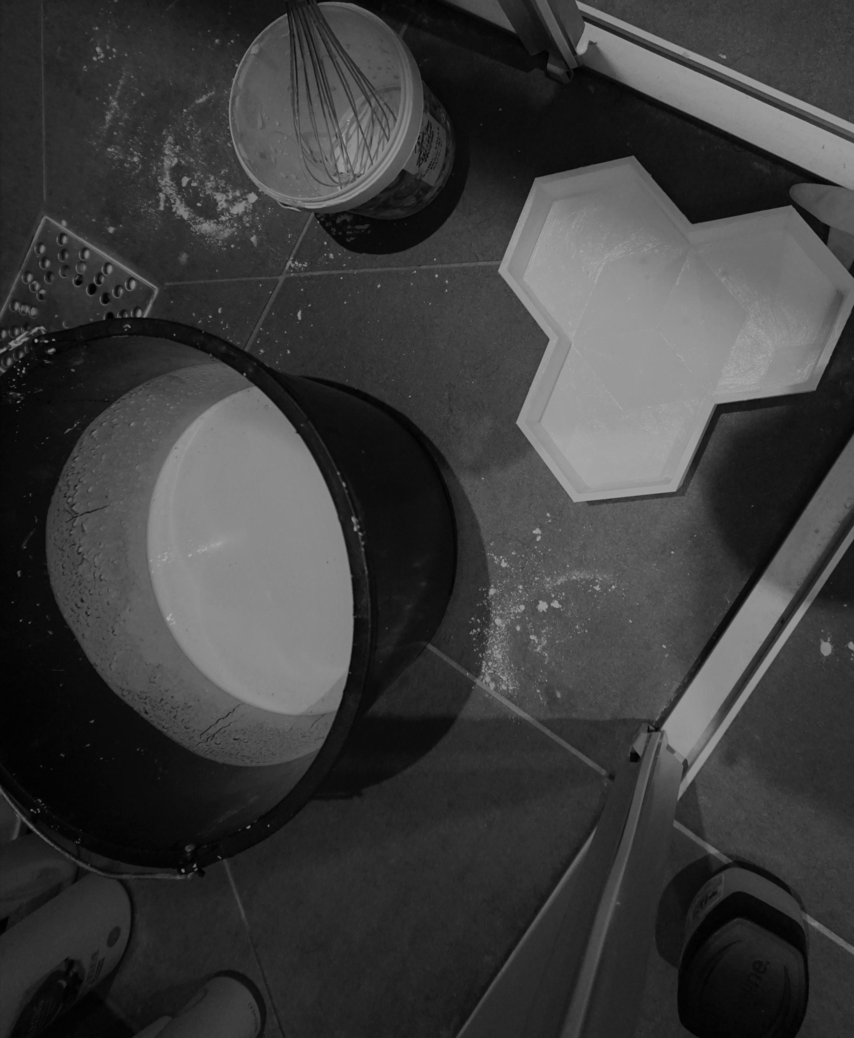
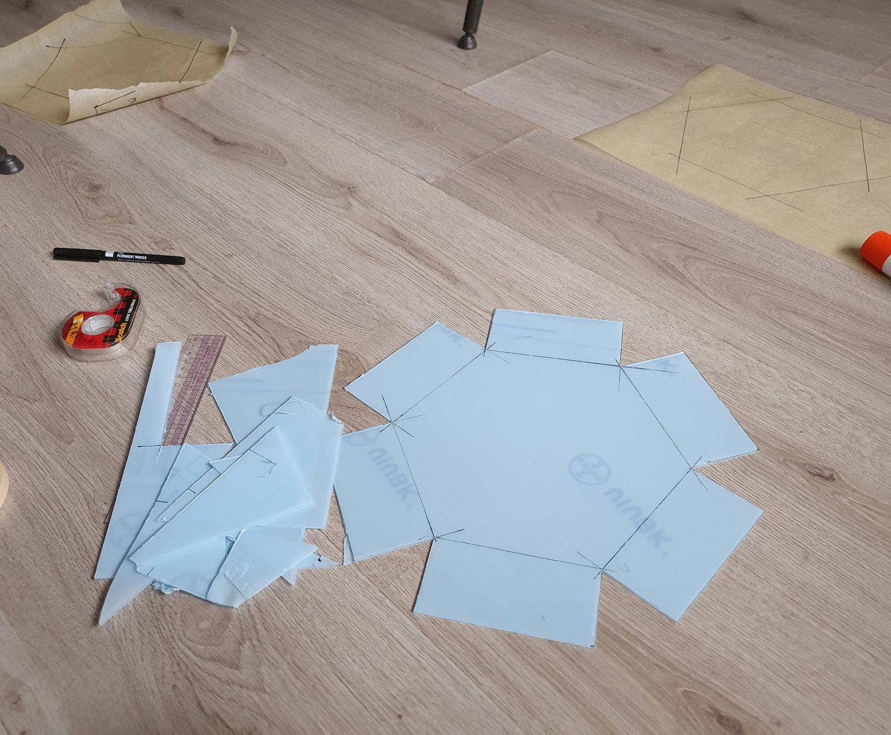 Mold making tools.
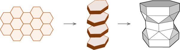
Form making strategy.
Mold making tools.
Form making strategy.
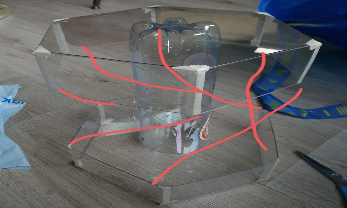

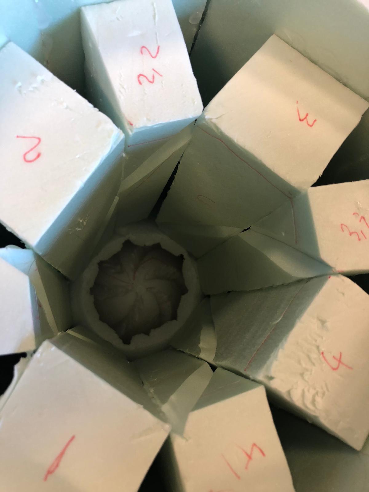
 Mesh mold; streight surrounding.
Mesh mold; the base and the top.
Mesh mold; twisted surrounding.
Mesh mold; streight surrounding.
Mesh mold; the base and the top.
Mesh mold; twisted surrounding.
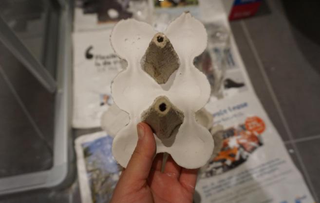
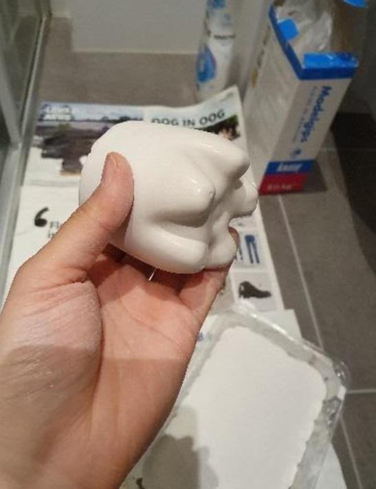
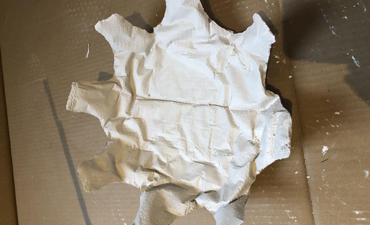
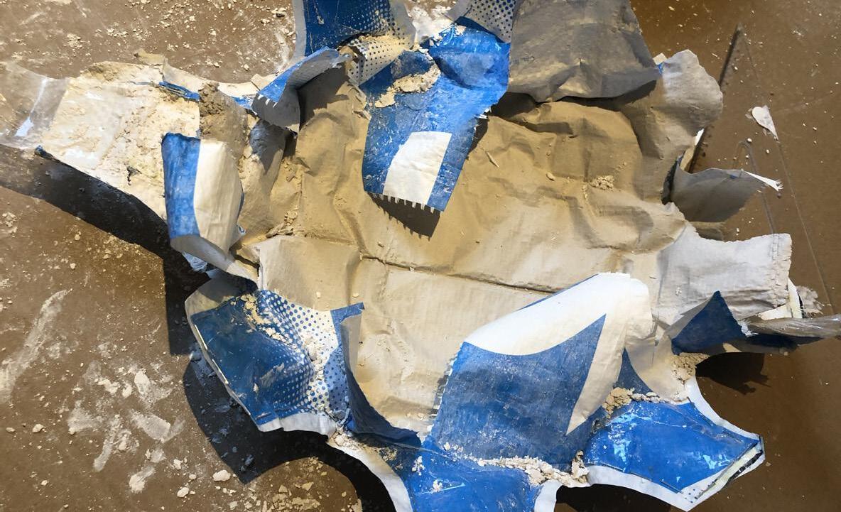
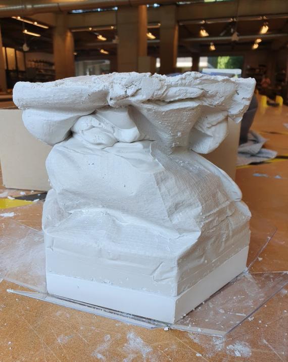
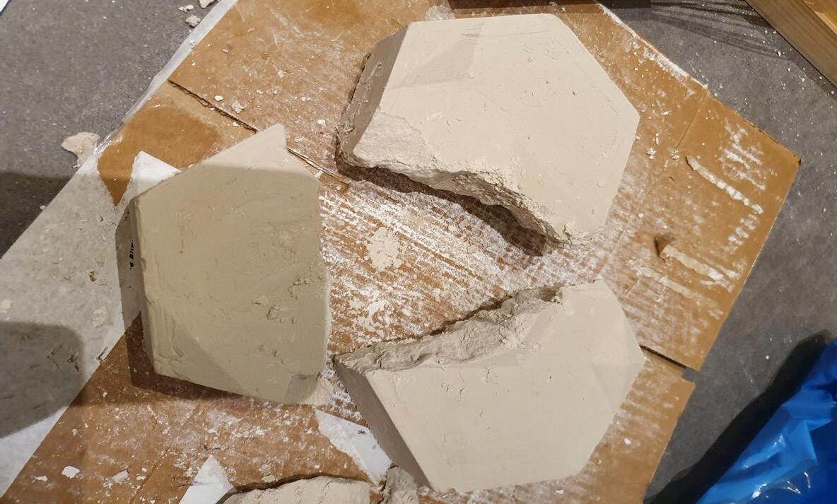
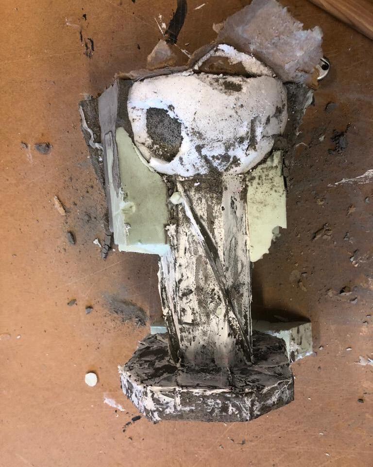 Un-molding.
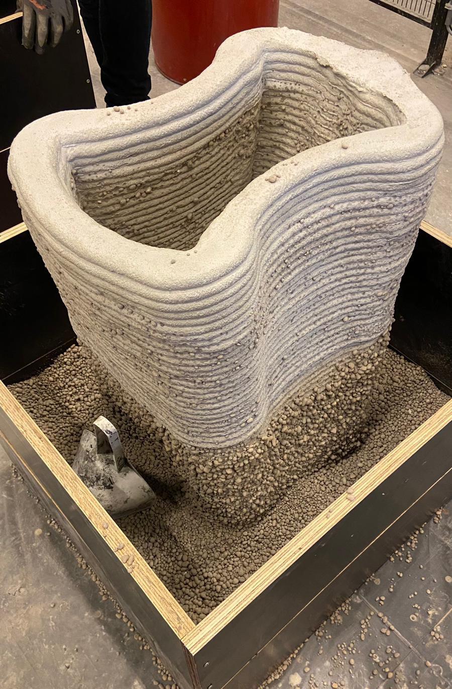
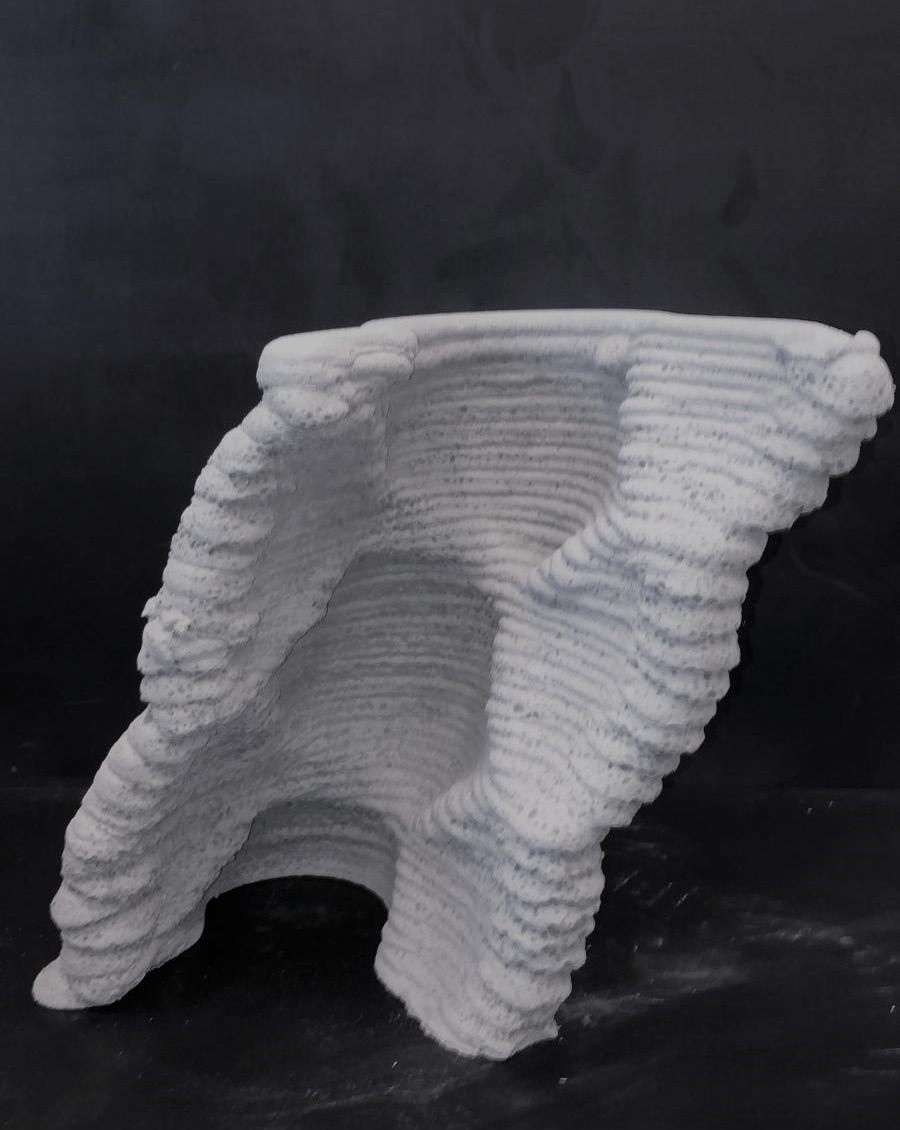
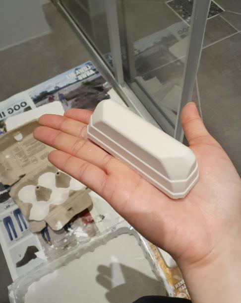
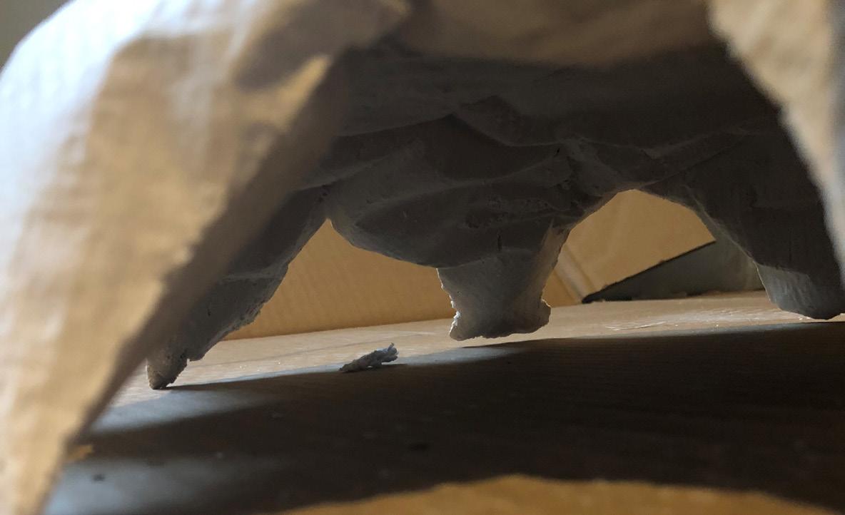
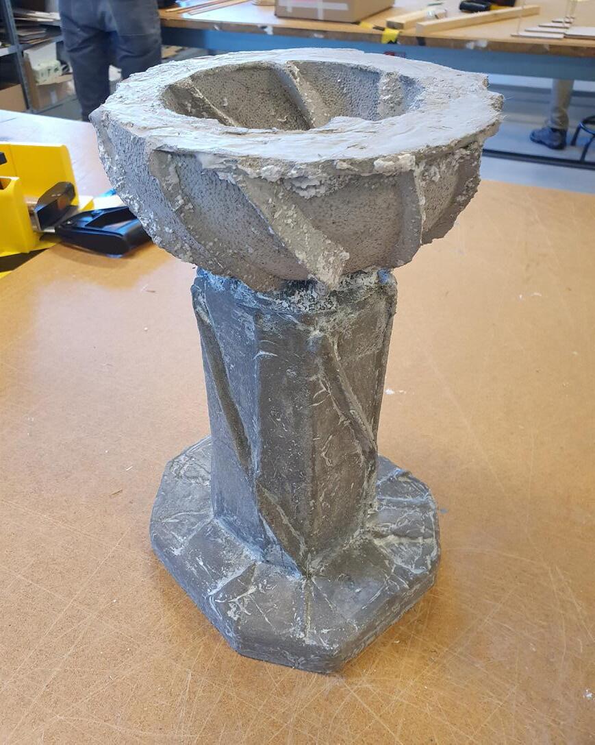
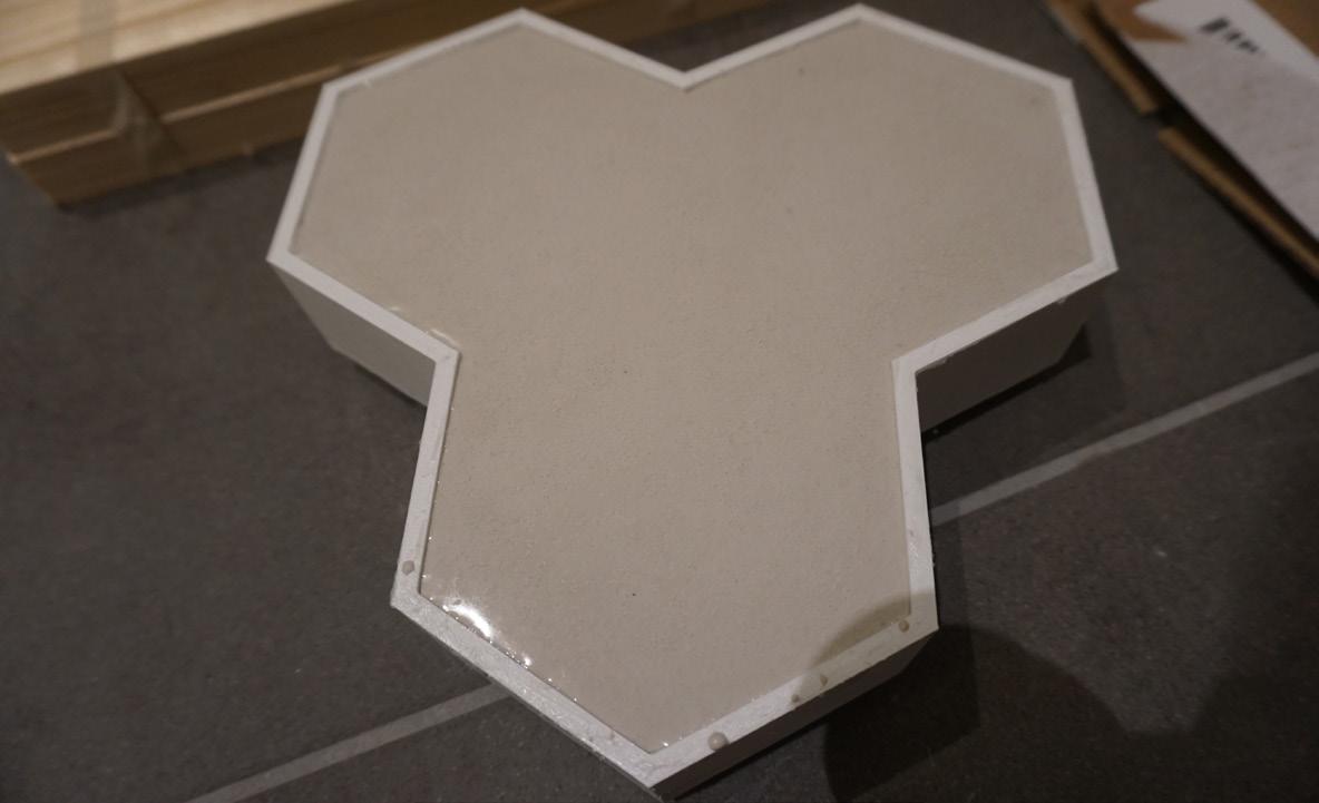
Solid mold; inside veiw. Final result.
Pouring the concrete.
Un-molding.
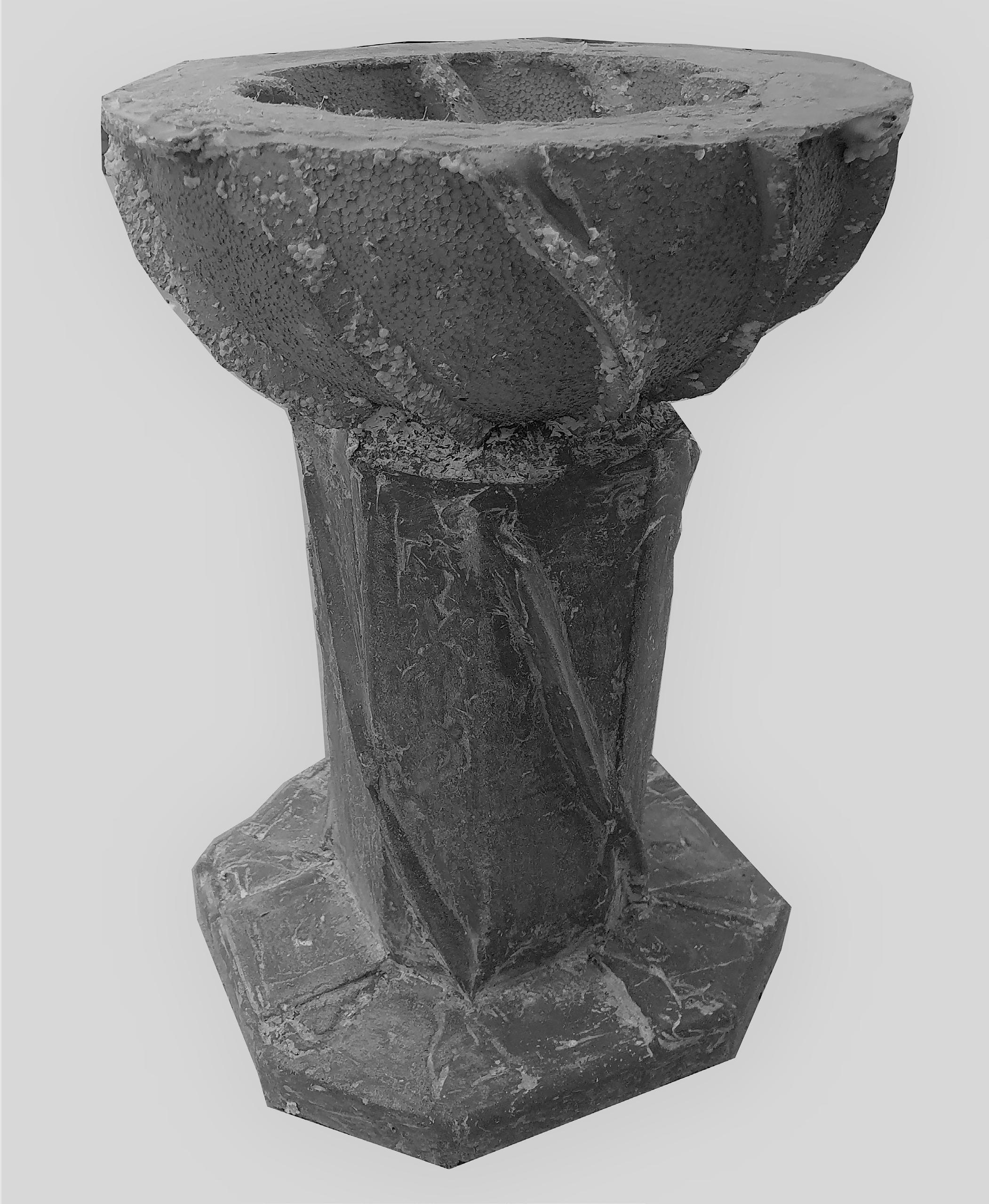
Solid mold; inside veiw. Final result.
Pouring the concrete.
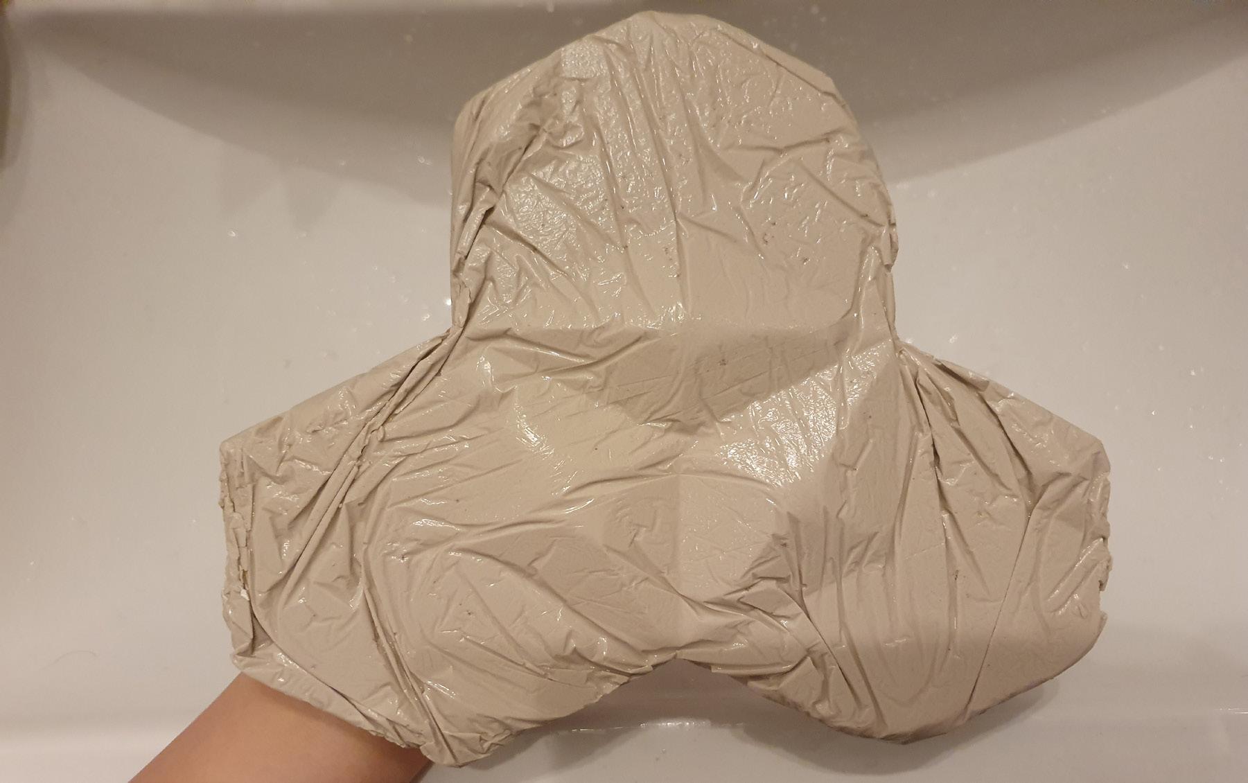
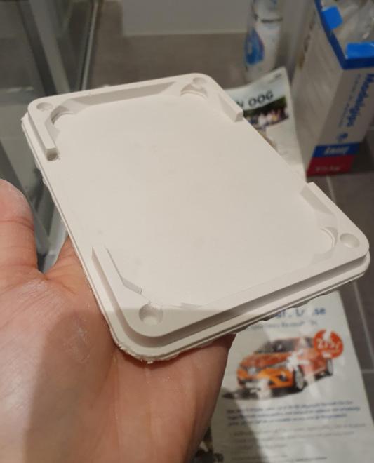
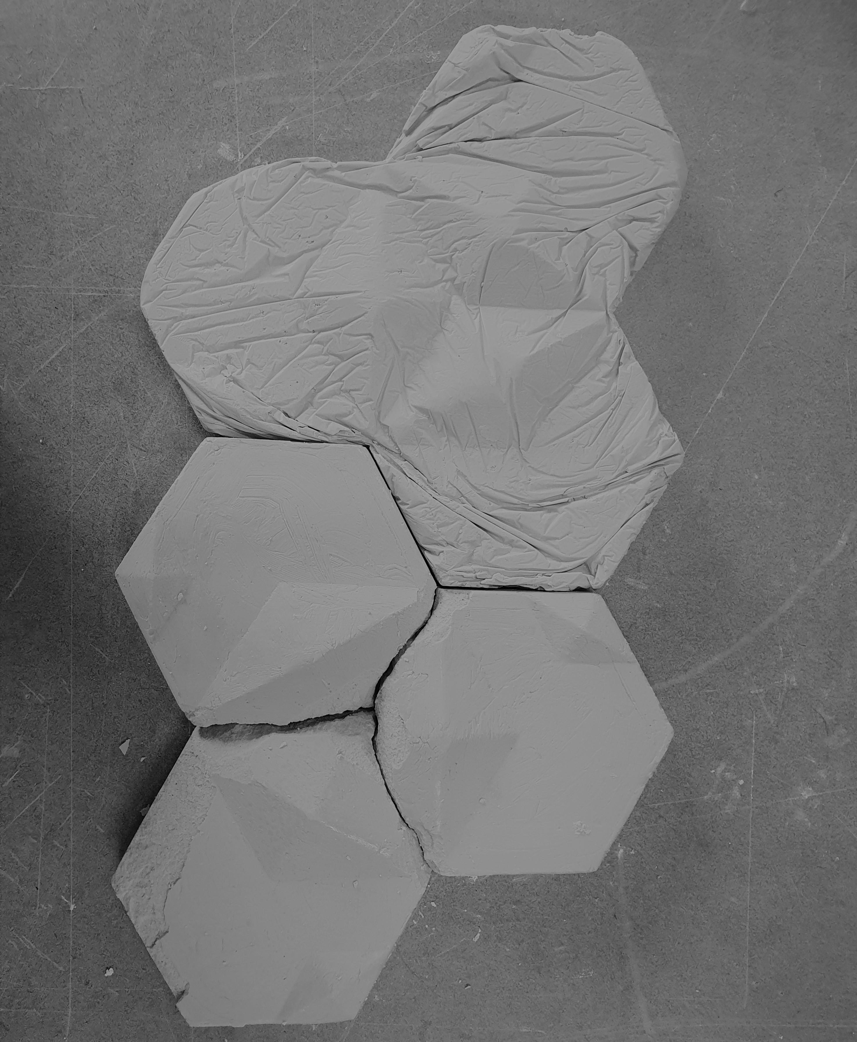
 The final result after using plastic foil for covering.
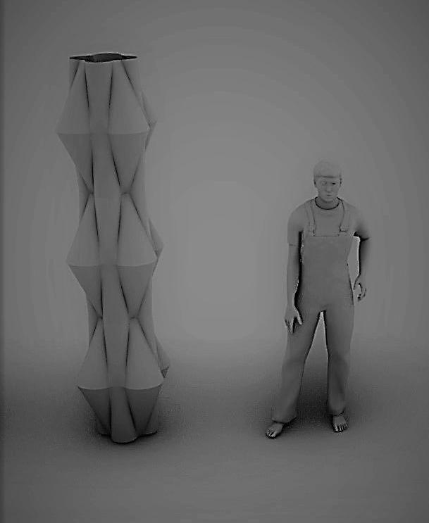
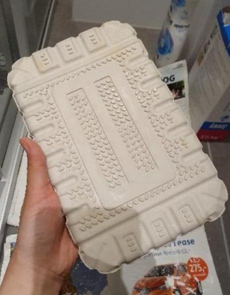
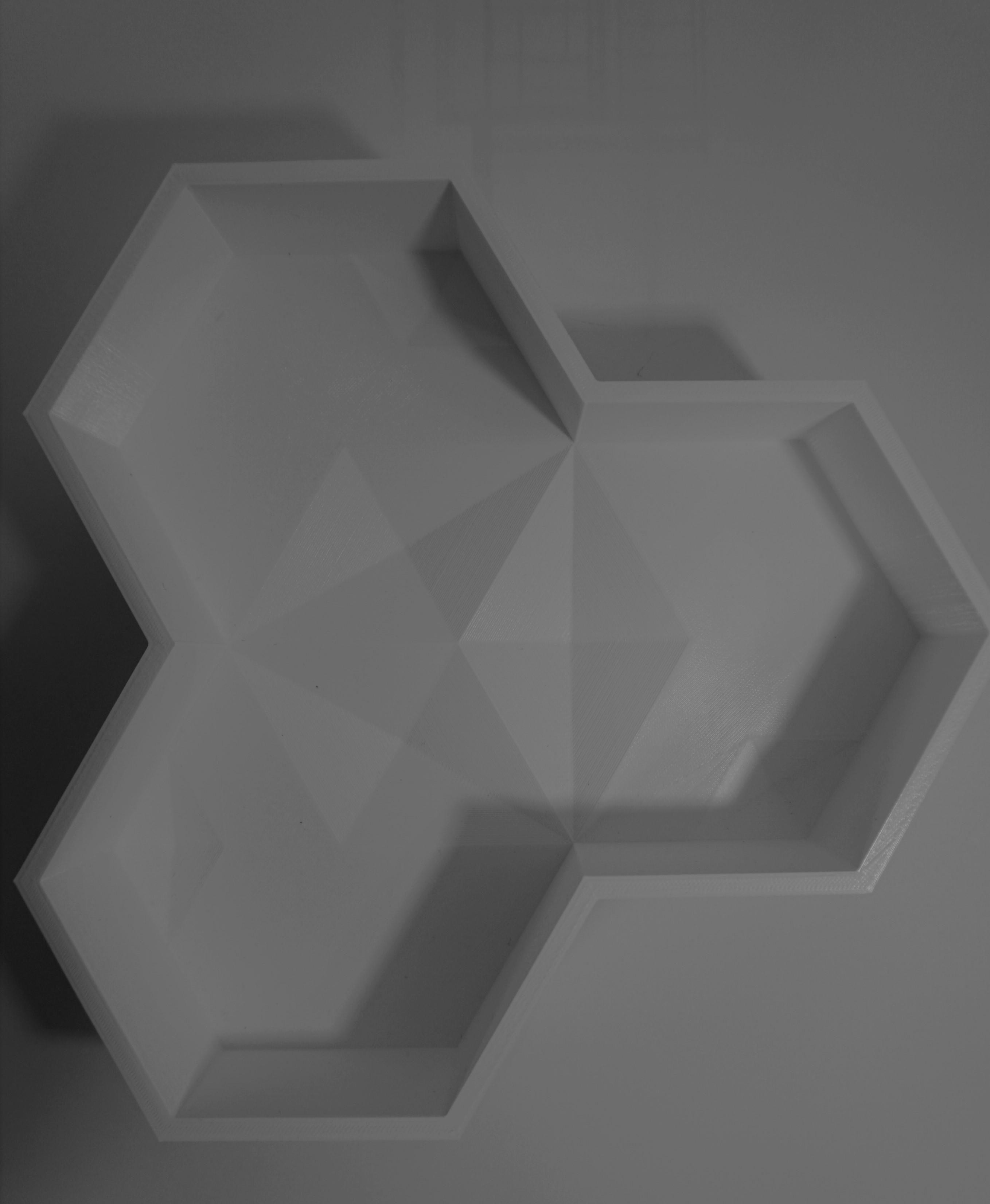
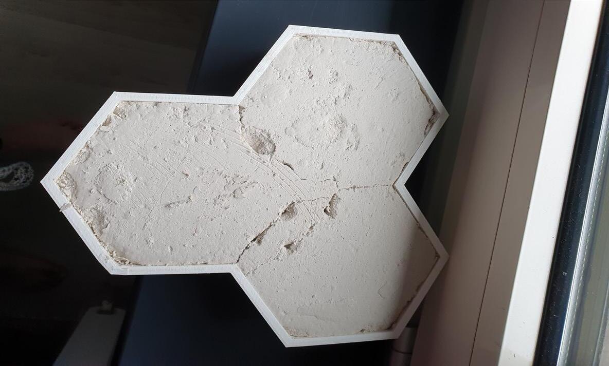
 Final results of the PLA mold.
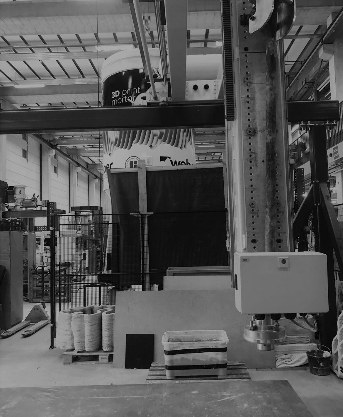
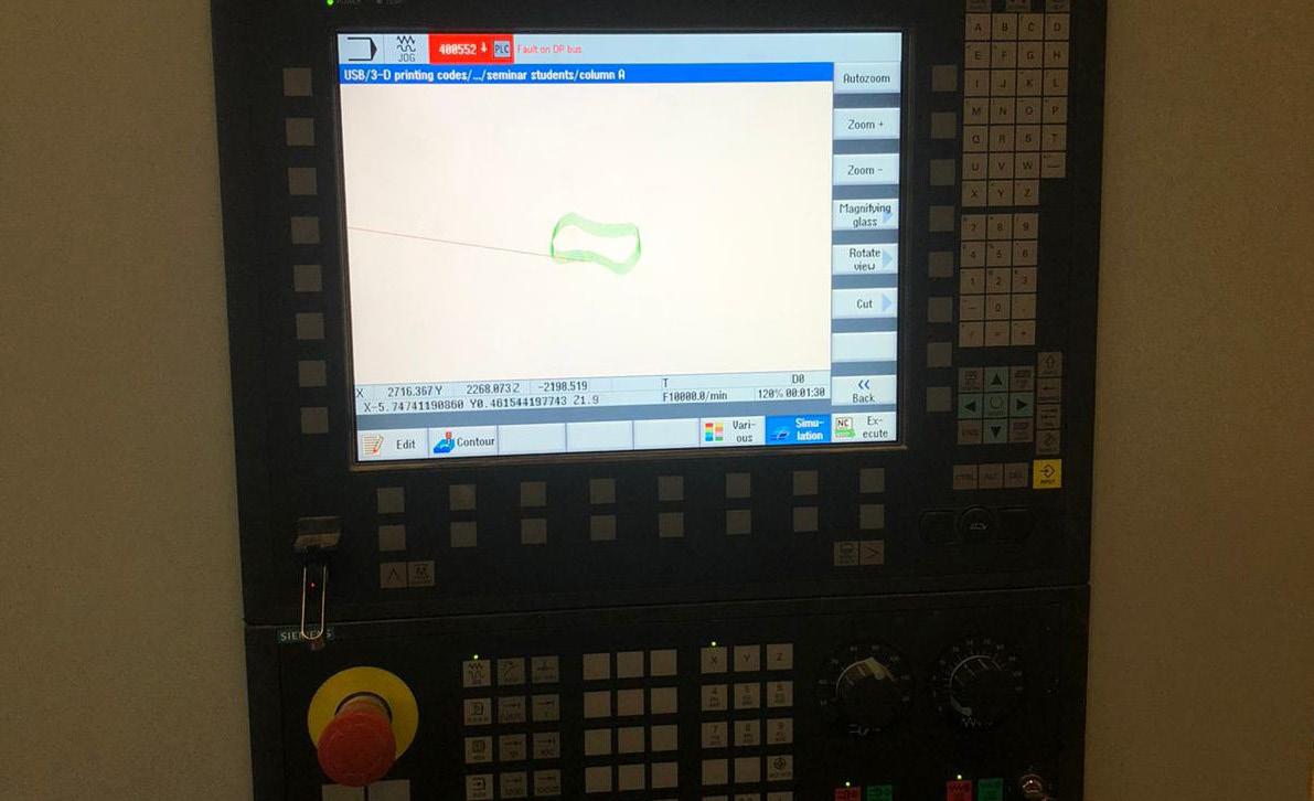
 3DCP Control unite
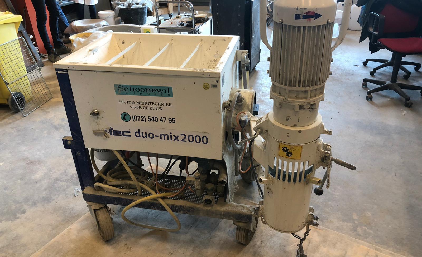
3DCP mixing machine.
3DCP Printing nozzel
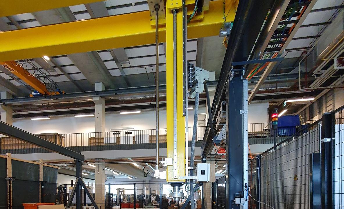
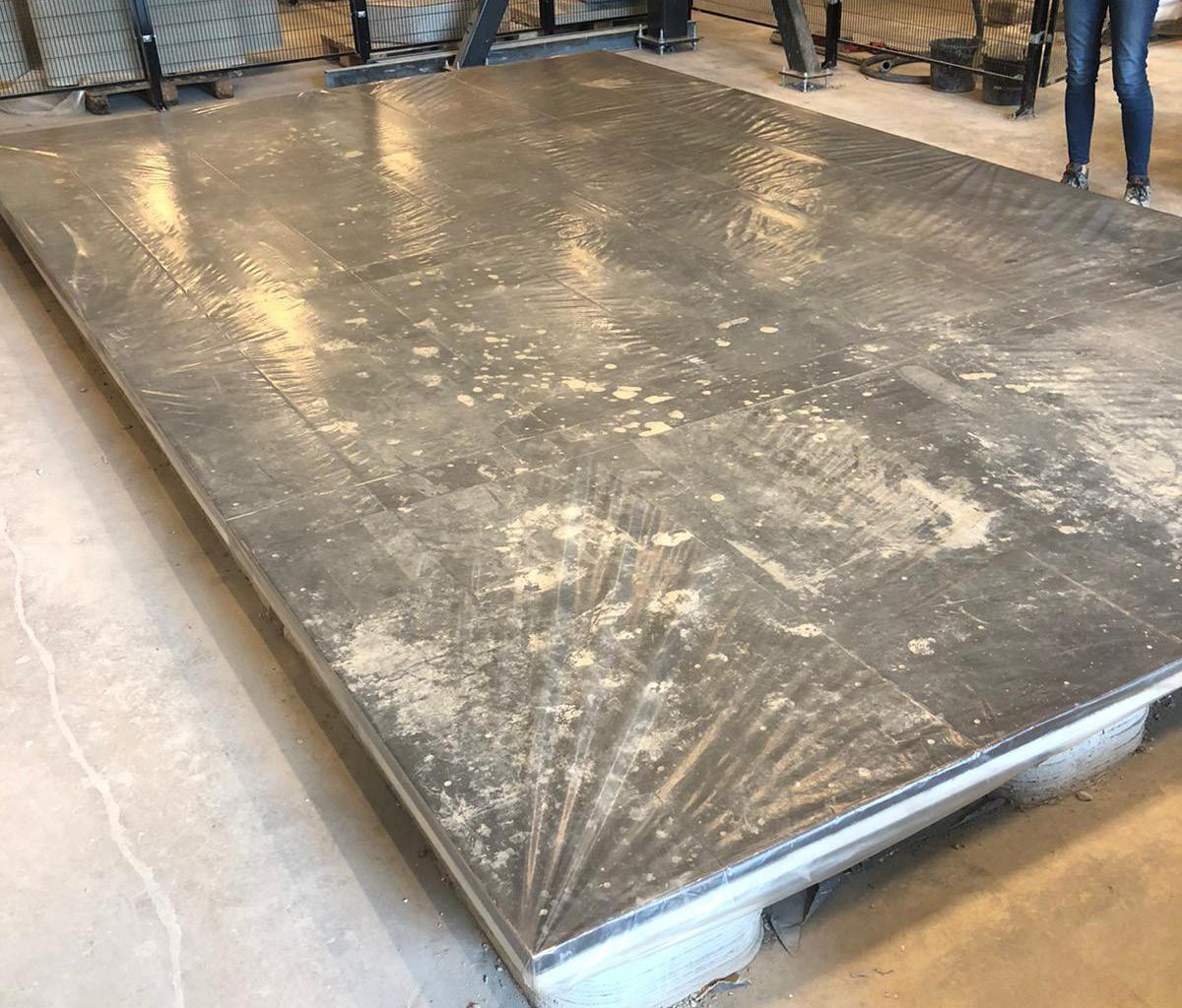
3DCP platform.
3DCP Control unite
3DCP mixing machine.
3DCP Printing nozzel
3DCP platform.