4 minute read
Model Organization


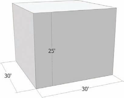
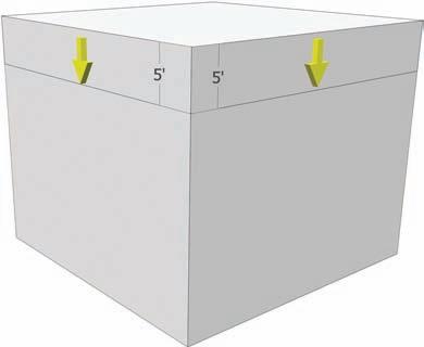
Fig. 2-32: Draw a 30´ × 30´ rectangle. Push/Pull the face 25´ in height. Fig. 2-33: Select the top edges of the cube and copy them downward 5´, using the vertical edges of the cube for reference.
Advertisement
The copied edges have further subdivided all four faces of the volume. The subdivided faces can be further manipulated; Push/Pull can be applied to move the faces in or out (Fig. 2-34).
Model Organization
Two very important and synergistic systems are used to organize model geometry. The Components and Groups system is described in detail in the next chapter; it helps consolidate geometry into bundles. These bundles can then be placed on the second system, called layers, providing users with the ability to toggle the visibility (on/off) of the bundles.

Fig. 2-34: The resulting subdivision in faces can be Push/Pulled in any direction.
Layers
Layers (Window > Layers) are the most important organizational tool in SketchUp. Using layers correctly is essential to efficient modeling; layers affect the modeling process and computer performance.
Specifically, layers control the visibility of SketchUp geometry. Turning off a layer will make the geometry on the layer invisible. Alternatively, toggling on a layer makes the geometry on that layer visible.
SketchUp models can contain loads of geometry. The more visible geometry there is, the more likely it is that computer performance will be slowed, thereby hindering work production. Furthermore, having a lot of visible objects can impede your ability to navigate within the SketchUp 3D environment because the geometry starts to get in the way.
By placing edges and faces on layers and using those layers properly, you can minimize or eliminate the challenges created by abundant geometry.
Layer 0
Layer 0 is the default layer in SketchUp (Fig. 2-35). Whenever a face, line, or edge is drawn in SketchUp, it should be drawn on Layer 0. (Make sure the Layer Dialogue box has a little black dot “on” to the left of Layer 0.) Modeling on Layer 0 will prevent drawn faces and edges from ending up on other layers and from conflicting with geometry as more detail is added.
Fig. 2-35: A typical site model layer list.

ChaPter 3
Components and Groups
SketchUp has a unique way of organizing edges and faces into easy-to-manage bundles of geometry. Two or more edges or faces can be made into a component or group. These combined edges and faces become a single item that can be easily replicated and edited. Creating components and groups allows for greater flexibility when you work with geometry.
Components and groups are the mainstays of constructing and organizing geometry. Completed and detailed site and building models are filled with them. You should become very familiar with how they work.
The advantages of using components and groups are:
They can be edited, copied, moved, rotated, or deleted. 33
They can be moved away from adjacent geometry. Ungrouped or noncomponent edges 33 and faces stick to other geometry. Components and groups are self-contained and not sticky.
They can be easily placed on their own layer. (Layers are discussed later in this chapter.)33
Components and groups are almost identical; however, they have one important difference: Editing or altering a component affects every instance of that component. Although multiple copies of a group are identical, editing one group has no effect on other copies of that group.
Tutorial: With the Rectangle tool, create a face that is 10´ × 10´. Use Push/Pull to add volume 10´ in height (Fig. 3-1). With the Select tool, select all the geometry (edges and faces) that composes the cube. Hover over the selection and right-click. This will bring up a context menu. Select Make Component. Enter a name in the dialogue box (Cube, for example) and select OK. Make sure that the Replace Selection with Component option is checked. A blue outline will appear around the cube. It is now a component (Fig. 3-1).
Using Move/Copy, make five copies of the cube and place them in a row next to the original (Fig. 3-2, Fig. 3-3).
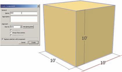
Fig. 3-1: Draft a 10´ × 10 ´ × 10´ cube. Select the entire object and right-click. From the menu, select Make Component. Name the new component Cube.

Fig. 3-2: With the Move/Copy tool, make a copy of the component and place it next to the original.
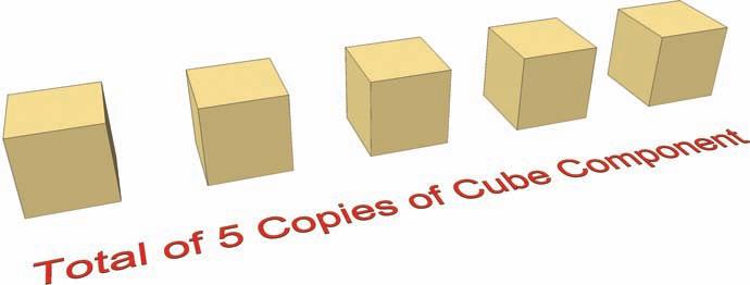
Fig. 3-3: With the Move/Copy tool, make additonal copies of the cube.


