4 minute read
Drawing the Base


Let’s begin by modeling a built environment from scratch. The following exercise will: Introduce the typical composition of a Flatwork Base. In it, you will carve up a rectangular 33 3D face to create individual surfaces that define the built environment—a road, sidewalk, tree lawn, curving trail, building footprint, steps, and walls. Familiarize yourself with the process of drafting the Flatwork Base, including organiz33 ing and using the drawing tools and layers. Later in this chapter, you’ll learn how to add objects to the Flatwork Base.
Drawing the Base
Advertisement
Using the Draw tools to draft a simple Flatwork Base, follow these steps: 1. Draw the base (Fig. 6-7). a. Open Layers (Window > Layers) and make sure Layer 0 is current (it should be). Select the Rectangle tool.
b. Draw a 100´ × 100´ rectangular surface by selecting the first rectangle draw point, typing 100´, 100´, and pressing Enter. The generated rectangular face will be used to compose the Flatwork Base. The Draw tools will be used to subdivide the face into smaller individual faces.
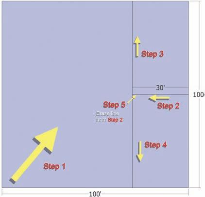
2. Define the road (Fig 6-7). a. Using the Line tool, find the midpoint (cyan box) of the right edge of the rectangle. Snap to the midpoint and draw toward the center of the rectangle, perpendicular to the drawing edge b. Enter the value 30’ (in the VCB). This will draw a 30´ line perpendicular to the right edge. 3. Continue to define the road.
a. Continue to draw a perpendicular line from the endpoint of the 30´ line to the top edge of the rectangle. This will create the first subdivided face on the surface. b. Using the Select tool (black arrow), select the smaller surface area. The surface is its own subdivided face. Deselect the face by hitting CRTL+T. This command allows you to deselect any selected geometry.
Fig. 6-7: Drafting the Flatwork Base and defining the road.
4. Continue to define the road.
a. From the endpoint of the first line, draw another line to the bottom edge of the rectangle. 5. Continue to define the road.
a. Use the Eraser tool and erase the first drawn line (from step 2). This combines the smaller surfaces into a single surface.
The subdivided surface represents the road. 6. Define the sidewalk and tree lawn (Fig. 6-8). a. With the Select tool, select the line drawn in the previous section. b. With the line selected, select the Move/Copy tool (View > Toolbars > Modification menu > Move/Copy). c. With Move/Copy active, select the bottom endpoint of the line. Hold Ctrl and Click+drag the mouse to the left, using the bottom edge for reference. Type 8´ (in the VCB) and press Enter.
A copy of the line is created 8´ from the edge. The narrow area between the two lines should be its own selectable face.
7. Continue to define the sidewalk and tree lawn:
a. Select the newly copied line and Move/Copy the line 5´ to the left, by repeating step 6.
The two narrow surface areas represent the tree lawn and concrete walk. 8. Add a curved trail (Fig. 6-8). a. Select the Arc tool. Approximately a quarter of the way up from the bottom-left corner of the initial rectangle, start to draw an arc, snapping to the left edge, moving to the right, perpendicular to the left edge. b. Snap the second arc point to the copied line generated in step 7. c. Select the third point to define the radius of the arc (the bulge). Make sure to snap to the On Face inference point. Give the arc a gentle curve, as shown in Fig. 6-8. 9. Duplicate the arc to define the trail. (Fig. 6-8). a. Using the Offset tool (View > Toolbars > Modification menu > Offset), create a duplicate of the drawn arc. Select the arc and offset the arc line 6´ going “south” on the surface.
Fig. 6-8: Drafting the walks and trails

Notice that the endpoints of the offset arc do not touch or connect to either of the adjacent edges. This will prevent the area defined for the trail (between the two arcs) from being subdivided. 10. Define the curved trail.
a. Zoom into both ends of the offset arc and use the Line tool to draw an edge from the endpoint of the arc to the adjacent line. b. Check to see that the added edges now subdivide the area between the arc into a separate surface. This surface will be the trail. 11. Build a building footprint (Fig. 6-9). a. Starting from the top-left corner, draw a 50´ × 25´ rectangle that is 13´-6˝ from the far left edge and 13´-6˝ down from the top edge. b. The Rectangle tool has subdivided the large area. This smaller surface represents the footprint of the building. 12. Add a building entry path (Fig. 6-9). a. Starting 25´ down from the top-right corner of the building footprint drawn in step 11, draw a perpendicular line to the right. Connect the line to the “walk” edge from step 7. 13. Continue adding a building entry path. a. With Move/Copy, make the walk 6´ wide by copying and moving the line drawn in step 12.
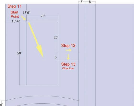
Fig. 6-9: Drawing the building footprint and building entry path.


