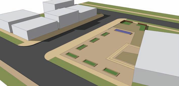
Let’s begin by modeling a built environment from scratch. The following exercise will: 33Introduce the typical composition of a Flatwork Base. In it, you will carve up a rectangular 3D face to create individual surfaces that define the built environment—a road, sidewalk, tree lawn, curving trail, building footprint, steps, and walls. 33Familiarize yourself with the process of drafting the Flatwork Base, including organizing and using the drawing tools and layers. Later in this chapter, you’ll learn how to add objects to the Flatwork Base.
Drawing the Base Using the Draw tools to draft a simple Flatwork Base, follow these steps: 1. Draw the base (Fig. 6-7).
a. Open Layers (Window > Layers) and make sure Layer 0 is current (it should be). Select the Rectangle tool. b. Draw a 100´ × 100´ rectangular surface by selecting the first rectangle draw point, typing 100´, 100´, and pressing Enter. The generated rectangular face will be used to compose the Flatwork Base. The Draw tools will be used to subdivide the face into smaller individual faces. 2. Define the road (Fig 6-7).
Fig. 6-7: Drafting the Flatwork Base and defining
a. Using the Line tool, find the midthe road. point (cyan box) of the right edge of the rectangle. Snap to the midpoint and draw toward the center of the rectangle, perpendicular to the drawing edge b. Enter the value 30’ (in the VCB). This will draw a 30´ line perpendicular to the right edge. 3. Continue to define the road.
a. Continue to draw a perpendicular line from the endpoint of the 30´ line to the top edge of the rectangle. This will create the first subdivided face on the surface. b. Using the Select tool (black arrow), select the smaller surface area. The surface is its own subdivided face. Deselect the face by hitting CRTL+T. This command allows you to deselect any selected geometry.
52
Part 2: SketchUp Process Modeling


