3 minute read
Campus Quad—Area 2


Campus Quad—Area 2
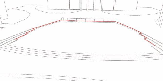
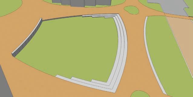
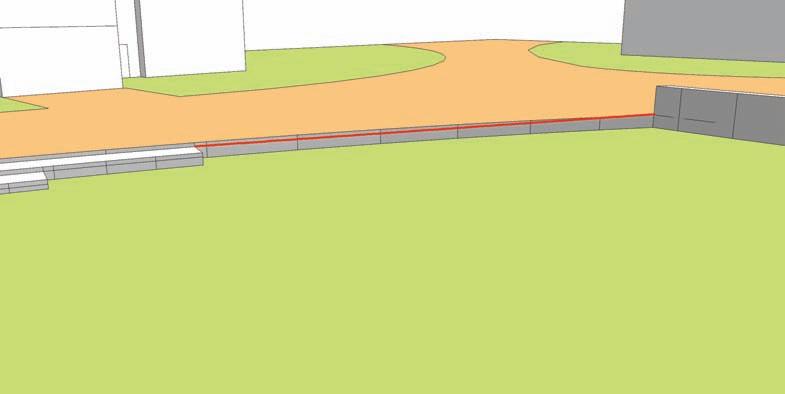
For this tutorial, locate Area 2. Carefully follow the diagrams for the drafting and placement of arcs and edges. You will need to create a wireframe that surrounds three sides of the green to be able to generate the desired terrain. 1. Identify Area 2 in the example model. Pinpoint the areas described in Area 2 that will be referenced in the tutorial. You are going to add a subtle slope to the steps and landscape area. The idea is to simulate steps that tie into the landscape or Green.
Advertisement
Back wall Ledge 1
Step location 1
Step location 2
Ledge 2
Step location 3
Step location 4
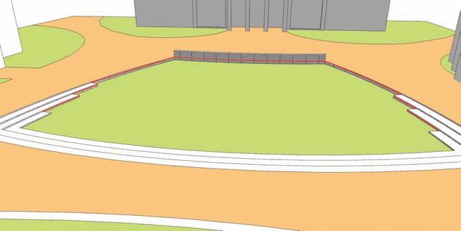
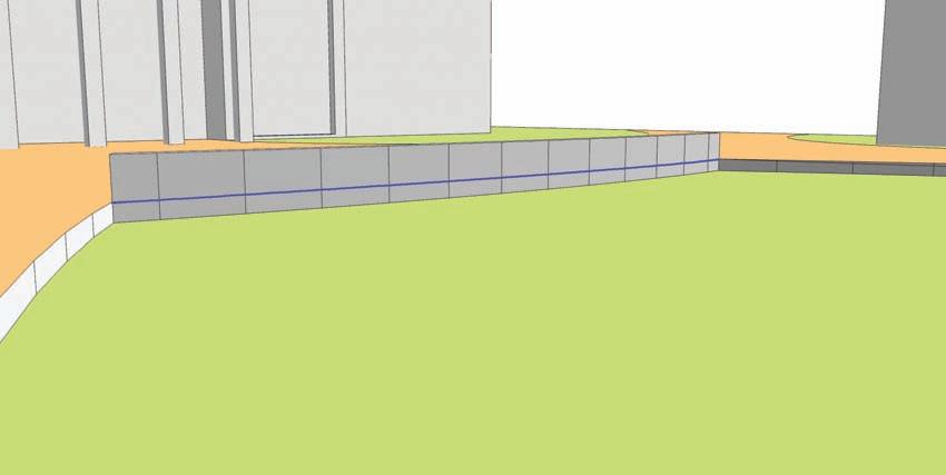
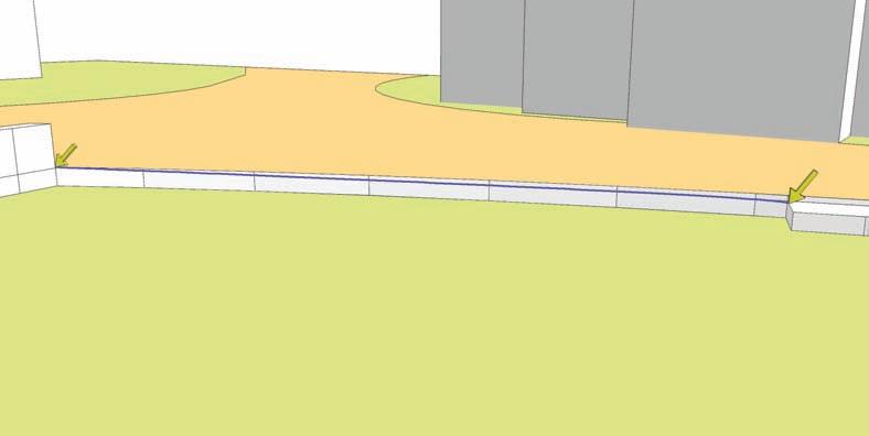
2. Starting with the Back Wall location, copy the top edges of the wall (facing toward the
Green) downward, snapping the copied edges to the intersections of Ledges 1 and 2. This is the first set of edges that will be used to generate a simulated terrain.
Back wall Top edge
Endpoint of ledge 2 Endpoint of ledge 1
3. Draw an arc from the intersection of the wall and edge at the end point of ledge 1 to the top of Step Location 1. Snap the midpoint of the arc to the vertical faces of Ledge 1.
Do not snap the arc bulge to the top of the vertical surfaces but slightly below the lip of
Ledge 1. The arc could be partially hidden behind the vertical faces. As long as the arc is selectable, this will not pose any problems when creating the slope.
Endpoint of ledge 1 Ledge 1 Top of step location 1
4. Copy the edges of Step Location 1 to the endpoint of Step Location 2. Draw a line from the endpoint of the copied line to the endpoint of the arc generated in the previous step.
This is the small diagonal edge on the side of the step shown in the diagram.
Top of step location 2
Step location 1
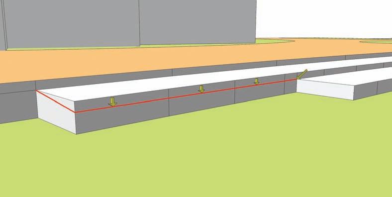
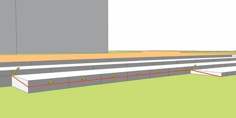
5. Copy the vertical edges of Step Location 2 downward and snap them to the top point of the lowest step. Connect the copied edge to the tops of the adjacent steps by adding diagonal lines at either end. One line should connect diagonally to the top of the step (at the endpoint of the edge copied in the previous step) and another edge should be placed diagonally to connect along the ground. Use the diagram for clarity.
Step location 2 Bottom Step
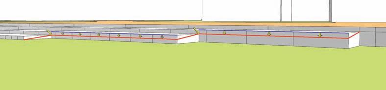
6. Repeat steps 3 through 5 on the opposite side of the Green. Repeat step 3 on the other side of the Green for Ledge 2 location, drafting an arc from the back of the wall to the top of Step Location 3.
7. Repeat steps 4 and 5 on Step Locations 3 and 4 on the other side of the Green. This will complete the creation of the wireframe.
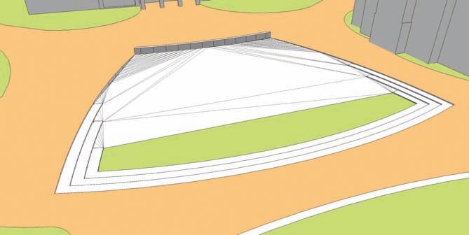
8. Select all the drafted and copied edges in steps 2 through 7. Activate the From Contour tool.
The From Contour tool will stitch the selected edges, generating a simulated slope.