4 minute read
Simple Canopy Tutorial
The height of all the vertical edges should be equal to the tallest point the object will 33 have when completed.
Vertical edges will be added to the endpoints of all 2D plan endpoints and some 33 midpoints.
Advertisement
Add a vertical edge to the endpoints and midpoints of all 2D arcs on the plans. The 33 use of two-dimensional arcs with vertical edges will be used to create projected arcs upward in 3D space.
The vertical edge placed at the midpoint of the 2D arcs helps you determine the bulge 33 (third point) of an arc in space. Arcs are the primary edges used to de33 fine organic, complex, and curved faces.
When assessing the wireframe, do not hesitate to add additional edges that will help 33 define the form. The more specific and detailed the wire frame, the more accurate the final model will be.
Once the form is generated with From Contour, delete the 2D plan and vertical refer33 ence edges. Clean up any artifact faces generated by From Contours.
The tutorials outline two very specific structures that can be created using construction geometry. However, you can utilize the general methods outlined here and experiment to create your own forms, objects, and structures.
In this tutorial, you will make a simple canopy.
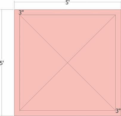
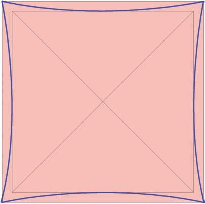
Download Model: Simple_Canopy 1. Draft a 5´ × 5´ rectangle. Offset the rectangle face 3˝ inward. Then draw two diagonal edges from corner to corner of the offset face, as indicated by the diagram. This forms the 2D base that will be used to generate a 3D canopy. 2. Draft 4 arcs between the outer edges and the edges offset in the previous step. The arcs should be snapped from endpoint to endpoint of the square’s outer edges. Snap the bulge of the arc to the midpoint of the interior edge that was offset in the previous step.
3. Delete the outside edges of the rectangle. The arcs should have subdivided the 3˝ wide face. Deleting the edges will leave faces defined by the outer lines of the arcs. You can begin to see the basic form of the canopy.
Midpoints of offset square
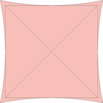
4. At the center of the surface (the point of intersection of the diagonal lines), draft a 1´ vertical edge. This edge will define the highest point of the canopy.

5. At the midpoint of two adjacent outer edge arcs, draft a 3˝ high vertical line. Only add the edges to these two arcs.
Midpoint of arc

Midpoint of arc
6. Draw two arcs. Start from opposite corners and snap the bulge of the arc to the top endpoint of the 1´ vertical edge drafted in step 4. Once these arcs are snapped to the top of the 1´ edge, the arc lines will be subdivided in half.
Arc 2
Arc 1
Top endpoint of 1´ vertical edge
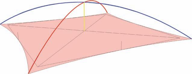
7. Add another arc snapping to opposite corner endpoints. Snap the arc bulge to the top of the 3˝ edge included in step 5.
Top of 3˝ vertical edge

Arc 1
Endpoint Endpoint
8. Select the edges as indicated in the diagram. Select the arc drawn in step 7. Next, select the two half arcs created in step 6. The two arcs should be the ones connected/adjacent to the arc from step 7. Activate the From Contour tool to stitch the edges with faces.
9. A series of faces creating an organic shape or canopy will be generated. Enter the From
Contour generated group instance and with the hidden geometry visible, delete all the artifact faces below the arc from step 7.
10. Apply a color to the canopy surface group.

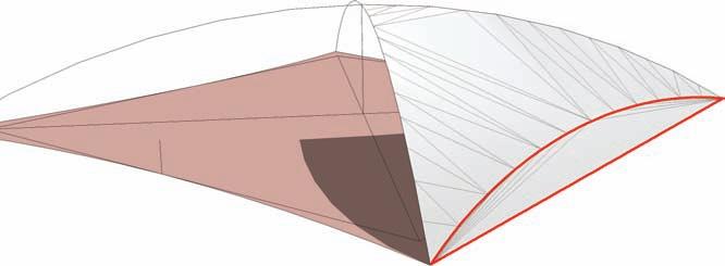

11. Use the rotate tool and copy the Canopy group 45 degrees: Select the Canopy group. Next, activate the Rotate tool. Snap the first rotate point to the bottom endpoint of the 1´ vertical edge. Snap the second rotate point to the bottom endpoint of the 3˝ vertical edge 1 connected to the Canopy Group. Holding the Crtl key, select the third rotate point. Snap the third point to the bottom endpoint of the adjacent 3˝ vertical edge 2.
This will create a copy of the Canopy group at 45 degrees.
1´ vertical edge Canopy surface 3˝ vertical edge 1
Central rotation point

3˝ vertical edge 2
Holding Ctrl will create a copy of the Canopy group at 45 degrees to the original.

12. Immediately enter 3x into the VCB. This will create two additional copies of the Canopy group rotated around the center axis at 45 degrees.
Select all four canopy surface groups and make them into a single component. Call the component Small Canopy. Delete the 2D base and vertical edges.
13. Elevate the Canopy component 8´. Directly below, draft a small circle with a 2˝ radius. Push/Pull the face of the circle 8´ in height. Select the Tube and make it a component called Tube. Select both the Small Canopy and Tube and make them into a component called Sun Shade. Attempt to rotate each component within the Sun Shade to have a slight tilt as shown in the graphic.


