
7 minute read
Drafting Order


Identify all the surfaces before drafting. This will help you determine the drafting order. Also, surfaces provide reference points in which edges and faces can be connected (Fig. 7-7). Some typical hard surfaces include concrete, colored concrete, pavers, asphalt, stone, walls, curbs, and building footprints. Some typical landscape surfaces inlude lawns, crusher fines (gravel), and planting beds.
Fig. 7-7: Identify the site plan surfaces.
Advertisement
A bug in SketchUp versions 6 and below sometimes prevents faces from being subdivided after the lines are drawn to define an individual face. Working around the bug is easy, but figuring out how to do it will take some detective work. Make sure that all the faces are divided into their own areas. If they are not, try the following:
Make sure all the edges are snapped to other edges. 33
Make sure none of the lines overlap. Th33 is commonly occurs when the Offset tool is used. Delete and redraw the lines as needed to remove all the overlaps.
Delete an edge that composes the face that should be subdivided and redraw it. Go 33 around the edges, and delete and redraw lines until the face is subdivided.
Drafting Order
These steps, which will be described in more detail, provide general guidelines for drafting and for effectively using the inference system. First, draft the outline of the plan image. Gradually subdivide the surface into smaller, more detailed faces. Use all of the drafted geometry to snap and align the other edges and faces as more detail is added. The smallest surfaces (for example, steps and walls) should be the last geometry that you draft.
Perimeter edges and building footprints provide references for snapping and aligning other drafted geometry. First, draw the building footprints using the Rectangle tool. Snap the footprints to the outer edges of the rectangular drawing surface. Next, draw the outer edges of the site plan; in the example plan, this is the curb line between the plaza and the road. Notice that some of the perimeter edges can be snapped to a building footprint (Fig. 7-8).
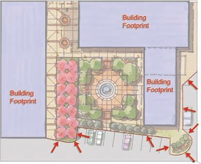
Fig. 7-8: Draft the building footprints and site perimeter.
Drafting the Identified Surfaces
Steps 1 through 7 are fairly complex. Read through the steps prior to attempting the tutorial. Draft the previously identified surfaces. Use the perimeter and building edges as references and snap points when applicable (Fig. 7-8).
Align the edges. The interior of the plaza, defined by the edges of the planter areas, is composed of several edges at right angles. Follow these steps to draw lines that are aligned, parallel, or perpendicular. Use the image as reference to locate all edges. 1. Draw a rectangle to define the main surface of the plaza (Rectangle 1) (Fig. 7-9). Further define the plaza edges using smaller rectangles. Draw a small rectangle (Rectangle 2) above the first rectangle (Fig. 7-10).
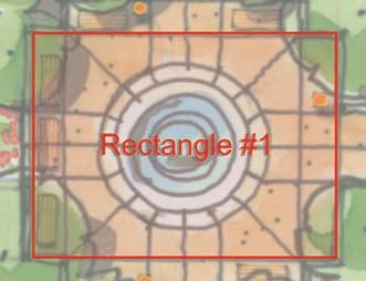
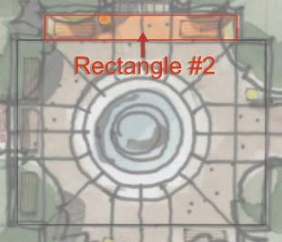
Fig. 7-9: Define the inner plaza with a rectangle. Fig. 7-10: Drawing the inner plaza.
2. Use the Tape Measure tool to draw construction guides from the right and left edge of Rectangle 2 to the bottom edge of Rectangle 1. At the intersection of the construction guides and Rectangle 1, draw Rectangle 3 to finish defining the interior plaza space (Fig. 7-11).
3. Draft Rectangle 4. Place Rectangle 4 over most of the tree lawn area (pink trees). Align the right edge of the rectangle with the corner endpoint of the perimeter edge (Fig. 7-12). 4. Draw Rectangle 5 over the indicated line work of the plan image. Align the top edge of the rectangle with the top edge of Rectangle 4 (Fig. 7-12). 5. Draw Rectangle 6; make sure to align the rectangle with the right and left edges of Rect- Fig. 7-11: Align the edges of Rectangle 3 with angle 5. Use construction lines to guarantee Rectangle 2. the alignment. The bottom edge of Rectangle 6 should end at the left corner of the planter indicated on the plan image (Fig. 7-12).
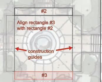

Fig. 7-12: Draw and align rectangles 4, 5, and 6 as indicated.
6. To create Rectangle 7, draw an edge from the midpoint of the left edge of the plaza to the right. Four feet above this line, on the outside edge of Rectangle 1, draw a 10´-6˝ × 8´ rectangle to define the entry (Fig. 7-13). 7. Draw the edges to complete each area as indicated in the diagrams. Make sure that the edges are drawn on axes (green and red) where applicable, and that the faces are subdivided. If faces do not subdivide, zoom in to the endpoints of the drawn line and make sure they are connected to the correct edges they were drawn to (Fig. 7-14 through Fig. 7-16).
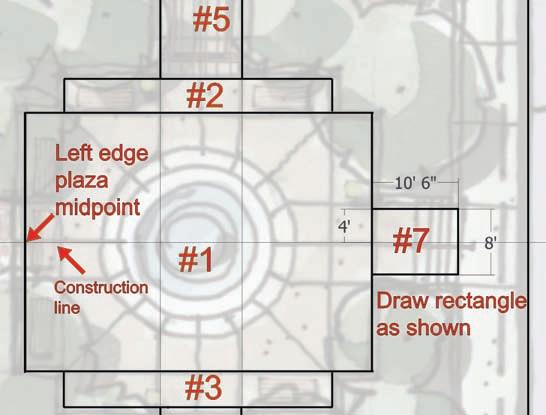
Fig. 7-13: When you draw Rectangle 7, align it with the left edge midpoint of the plaza.
Fig. 7-14: Draw lines 1 through 6 as shown. The idea is to connect and further define and subdivide areas of the plaza.
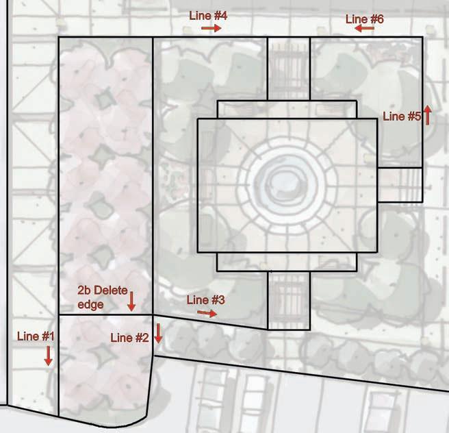

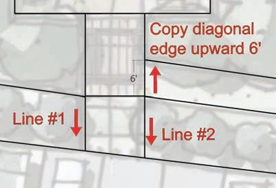
Fig. 7-15: Copy the diagonal edge (line 3 from Fig. 7-16) over to the right. Fig. 7-16: Add two lines from the bottom edge of the rectangle to the perimeter.
Adding the Small Edge Details
To draft the small details (steps, curbs, and walls), follow these steps. 1. Create the steps. a. Move/Copy the edges at the plaza’s bottom (rectangle 6) and (rectangle 7) east entries to create steps (Fig. 7-17). b. At the south entry, offset the edge 2´ to create a landing. Offset the landing edge to create three 1´-wide steps. c. At the east entry, from the right edge, offset three edges, each 1´ apart, to create three steps (Fig. 7-18).

Fig. 7-17: Move/Copy the steps and landing at the bottom entry (bottom of rectangle 6).
2. Create the entry sign wall and planting area. a. At the bottom right of the plan, trace a single arc to define one edge of the wall (Fig. 7-19). b. Offset the arc to create the wall thickness and to define the planter edges as shown in the plan. c. Further subdivide the wall and planting bed with arcs and lines (Fig. 7-20, Fig. 7-21). 3. Create the water feature located at the center of the plaza. a. Draw a diagonal line from one corner of the plaza to the opposite end. b. Use the Circle tool (View > Toolbars > Drawing > Circle) to draw a round surface on the midpoint of the diagonal line, matching the central circle on the plan (Fig. 7-22). c. Delete the diagonal line. Offset the first circle to match the concentric round edges, as shown in the image (Fig. 7-23). 4. Create the curbs. The edges between roads and walks and lawns are typically defined by a 6˝ curb. Adding curbs to models provides a visual cue to viewers; it conveys a subtle realism (Fig. 7-24).
Fig. 7-18: Move/Copy the steps at the right entry (right edge of rectangle 7).

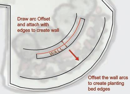
Fig. 7-19: Draft and Offset the arc to create the entry wall sign and planting area. Fig. 7-20: Apply arcs to further define the planting area.

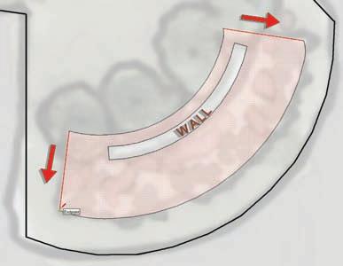
Fig. 7-21: Use edges to finish the planting area form and create the subdivided faces. Fig. 7-22: Place a circle at the center of the inner plaza.

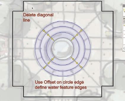

Fig. 7-23: Offset the center circle to create the fountain edges. Fig. 7-24: Area of plan that will have a curb.
a. Select the face of the surface where curbs can be located. Offset the face inward 6˝. This will offset all the edges that compose the surface (Fig. 7-25). b. Draw perpendicular lines between the edge of the road and the offset line at locations where the curb would end; curbs should be located only adjacent to the road (Fig. 7-26). Repeat this step for

Fig. 7-25: Offset the face to create edges used for a curb.


