
2 minute read
Balcony Component


2. In the unique component instance, draft the lines as indicated in the diagram. a. Offset the two large window faces 3˝. b. Draw a line down the center of each face along the midpoint. c. Draft a line across the face. Offset the horizontal line 2˝.
3. Paint the faces of the subdivided faces.
Advertisement
4. Repeat the previous steps and add door geometry to the indicated window on Building 2.

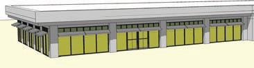
Balcony Component
This tutorial adds the Balcony component. The balcony component will be added to Building 3. 1. On the second-floor face of Building 3, between the first columns, draft a component for a balcony. a. Draft a 14´ × 8´ face, 6˝ from the bottom edge of the second level.
b. Delete the face, select the edges, and make the edges in a component called Balcony.

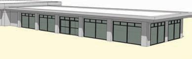
Building 3 columns
c. Within the component, heal the face. d. Offset the face 2˝.
2. Push/Pull the center face 4´ inward.
3. On the Push/Pull face from step 2, draft additional line work to define the balcony doors and windows. Offset the face 2˝. Draw in the window mullions (2˝ width), as shown in the diagram. Push/Pull the larger faces inward 3˝.


4. Add Translucent_Glass_Blue color to the window faces. Paint the mullions using
Color_001.
5. Offset the bottom edge of the balcony 6˝ inward. Offset it again 3˝. Make sure the face is subdivided.


6. Push/Pull the 3˝-wide face 3´ in height to create the balcony rail.
7. Copy/Array the Balcony component between the building columns.
8. Copy and Make Unique the window and door components from Building 2. Place them along the faces of the first floor of Building 3.
Adjust the color of the copied window and door components glass to match the balcony color (Translucent_Glass_Blue).


9. Save the file.
Chapter 10
Arranging and Presenting the Model
Now that the Flatwork Base, custom site furnishings, and building architecture have been completed, you have one final step to complete your model. You still need to piece together all the geometry and components to create presentable images. As you read about the concepts presented in this chapter, you will update the Flatwork Base site plan model from Chapter 7.
In this chapter, you’ll be introduced to the following concepts:
Arranging vegetation and site-furnishing components33
Placing components in a logical order33
Creating and exporting scenes33
To complete the exercises in this chapter, you will need three types of 3D tree øø components. They are available with the Landscape Bonus pack available at www.sketchup.com (under Downloads > Bonus Packs > Landscape Architecture) or at www.formfonts.com. Review the end of Chapter 3: Components and Groups for detailed instructions on obtaining components.


