
35 minute read
4.8 Managing System
4.8.1 General
4.8.1.1 Basic
You can configure device name, language and video standard.
Step 1 Select > System > General > Basic
Step 2 Configure general parameters.
Parameter Description
Name Enter the device name.
Video Standard Select video standard from PAL and NTSC.
Step 3 Click Apply.
4.8.1.2 Date & Time
You can configure date and time format, time zone, current time, DST (Daylight Saving Time) or NTP server.
Step 1 Select > System > General > Date & Time.
Step 2 Configure date and time parameters.
Table 4-27 Description of date and time parameters
Parameter Description
Date Format Configure the date format.
● Manually Setting: Configure the parameters manually.
Time
● NTP: When selecting NTP, the system then syncs time with the internet server in real time.
You can also enter the IP address, time zone, port, and interval of a PC which installed NTP server to use NTP.
Time Format
● Configure the display format of date and time. You can select from 12-Hour or 24-Hour.
Time Zone Configure the time zone that the camera is at.
Current Time Configure system time. Click Sync PC, and the system time changes to the PC time.
DST Enable DST as needed. Click , and configure start time and end time of DST with Date or Week.
Step 3 Click Apply.
4.8.1.3 Positioning System
Enter the camera’s location information (longitude, latitude, altitude, and installation height) to remind you where your camera locates.
Also, automatically sent to the management platform, the location information can be viewed on the platform to help the platform operator track your camera.
Step 1 Select > System > General > Positioning System
Step 2 Enter the longitude, latitude, altitude, and installation height of the camera.
Step 3 Click Apply.
4.8.2 Account
You can manage users, such as add, delete, or edit them. Users include admin, added users and ONVIF users.
Managing users and groups are only available for administrator users.
● The max length of the user or group name is 31 characters which consists of number, letter, underline, dash, dot and @.
● The password must consist of 8 to 32 non-blank characters and contain at least two types of characters among upper case, lower case, number, and special character (excluding ' " ; : &).
● You can have 18 users and 8 groups at most.
● You can manage users through single user or group, and duplicate usernames or group names are not allowed. A user can only be in one group at a time, and the group users can own authorities within group authority range.
● Online users cannot edit their own authority.
● There is one admin by default which has highest authority.
● Select Anonymous Login, and then log in with only IP address instead of username and password. Anonymous users only have preview authorities. During anonymous login, click Logout, and then you can log in with other username.
4.8.2.1 User
4.8.2.1.1 Adding User
You are admin user by default. You can add users, and configure different authorities.

Procedure
Step 1 Select > System > Account > User
Step 2 Click Add User.

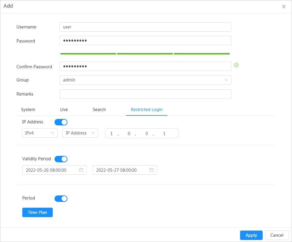
Table 4-28 Description of user parameters (1)
Parameter Description
Username User’s unique identification. You cannot use existed user name.
Password Enter password and confirm it again. The password must consist of 8 to 32 non-blank characters and contain at least two types of characters among upper case, lower case, number, and special character (excluding ' " ; : &).
Confirm Password
Group
The group that users belong to. Each group has different authorities.
Remark Describes the user.
Select permissions as needed.
System
It is recommended to give fewer permissions to normal users than premium users.
Live Select the live view permission to be enabled.
Search Select the playback and snapshot permissions to be enabled.
Set the PC address that allows the defined user to log in to the camera and the validity period and time range. You can log in to web with the defined IP in the defined time range of validity period.
● IP address: You can log in to web through the PC with the set IP.
● Validity period: You can log in to web in the set validity period.
● Time Range: You can log in to web in the set time range.
Set as following:
Restricted Login
1. Enable IP Address, and then select IP type and set the IP address.
◇ IP Address: Enter the IP address of the host to be added.
◇ IP segment: Enter the start address and end address of the host to be added.
2. Enable Validity Period, and then set the start time and end time.
3. Enable Period, and then click Time to set the period that allows login. For details, see Step4 in "4.6.1.2.1 Adding schedule"
Step 4 Click Apply
The newly added user is displayed in the user name list.
Related Operations
● Edit user information
Click to edit password, group, memo or permissions.
For admin user, you can only change the password.
● Click to delete the added users. Admin user cannot be deleted.
Admin user cannot be deleted.
4.8.2.1.2 Resetting Password
Enable the function, and you can reset password by clicking Forget password? on the login page For details, see "3.4 Resetting Password"
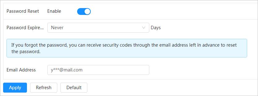
Step 1 Select > System > Account > User
Step 2 Click next to Enable in Password Reset
If the function is not enabled, you can only reset the password by resetting the camera.
Step 3 Enter the associated email address.
Step 4 Click Apply
4.8.2.2 Adding User Group
You have two groups named admin and user by default, and you can add new group, delete added group or edit group authority and memo.

Procedure
Step 1 Select > System > Account > Group
Step 2 Click Add.
Step 3 Enter the group name and memo, and then select group permissions.
Figure
Step 4 Click Apply
The newly added group displays in the group name list.
Related Operations
● click to edit password, group, memo or authorities.
● Click to delete the added users. Admin user cannot be deleted.
The admin group and user group cannot be deleted.
4.8.2.3 ONVIF User
You can add, delete ONVIF user, and change their passwords.
Procedure
Step 1 Select > System > Account > ONVIF User
Step 2 Click Add.
Step 3 Configure user parameters.

Figure 4-70 Add ONVIF user
Table 4-29 Description of ONVIF user parameters
Parameter Description
Username
User’s unique identification. You cannot use existed username.
Password Enter password and confirm it again.
Confirm Password
Group Name
Step 4 Click OK.
The password must consist of 8 to 32 non-blank characters and contain at least two types of characters among upper case, lower case, number, and special character (excluding ' " ; : &).
The group that users belong to. Each group has different authorities.
The newly added user displays in the username list.
Related Operations
● click to edit password, group, memo or authorities.
For admin account, you can only change the password.
● Click to delete the added users. Admin user cannot be deleted.
4.8.3 Peripheral Management
4.8.3.1 Configuring Heater
Step 1 Select > System > Peripheral > Heater
Step 2 Select the heater type to be Unit Device Heater.
This is supported by some select models.
Step 3 Set the heating mode.
● Auto: Set the start temperature and stop temperature as the temperature range for heater to start, and then click Apply. When the sensor temperature is in the range, then heater works automatically.
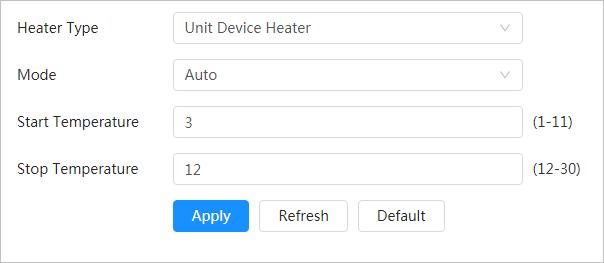
● Manual: When you think it’s cold enough and you want to let the camera work in a warm condition, you can select the mode to be Manual, click , and then click Apply.
Step 4 Click Apply.
4.8.3.2 Configuring Serial Port
Set the serial port of the external device.
Step 1 Select > System > Peripheral > Serial Port
Step 2 Configure parameters.
Parameter Description
Enter the corresponding device address, it is 1 by default.

IP Address
Make sure that the address is the same as the device address; otherwise you cannot control the device.
Baud Rate Configure device baud rate, it is 9600 by default.
Data Bit
Stop Bit
Parity
Step 3 Click Apply.
4.8.4 Manager
4.8.4.1 Requirements
It is 8 by default.
It is 1 by default.
It is none by default.
To make sure the system runs normally, maintain it as the following requirements:
● Check surveillance images regularly.
● Clear regularly user and user group information that are not frequently used.
● Change the password every three months. For details, see "4.8.2 Account".
● View system logs and analyze them, and process the abnormity in time.
● Back up the system configuration regularly.
● Restart the device and delete the old files regularly.
● Upgrade firmware in time.
4.8.4.2 Maintenance
You can restart the system manually, and set the time of auto reboot and auto deleting old files. This function is disabled by default.
Step 1 Select > System > Manager > Maintenance.
Step 2 Configure auto maintain parameters.
● Restart system:
Click next to Auto Reboot in Restart System, and set the reboot time, the system automatically restarts as the set time every week.
● Delete old files
Click next to Auto Delete in Delete Old Files, and set the time, the system automatically deletes old files as the set time. The time range is 1 to 31 days.
When you enable and confirm the Auto Delete function, the deleted files cannot be restored. Operate it carefully.

● Emergency maintenance
Enable AOL, and the system can be recovered with troubleshooting tools.
Step 3 Click Apply
4.8.4.3 Import/Export
● Export the system configuration file to back up the system configuration.
● Import system configuration file to make quick configuration or recover system configuration.
Step 1 Select > System > Manager > Import/Export.
Step 2 Import and export.
● Import: Select local configuration file, and click Import File to import the local system configuration file to the system.
● Export: Click Export Configuration file to export the system configuration file to local storage.
4.8.4.4 Default
Restore the device to default configuration or factory settings. This function will restore the device to default configuration or factory setting.

Be careful when doing operations such as “default” and “factory default”. The operations will result in data loss.
Select > System > Manager > Default
● Click Default, and then all the configurations except IP address and account are reset to default.

● Click Factory Default, and all the configurations are reset to factory settings.
4.8.5 Upgrade
Upgrading to the latest system can refine camera functions and improve stability. If wrong upgrade file has been used, restart the device; otherwise some functions might not work properly.
Step 1 Select > System > Upgrade
Step 2 Select an upgrading method you need and upgrade the system.
● File Upgrade
1. Click Browse, and upload upgrade file. The upgrade file should be a .bin file.
2. Click Upgrade to start the process.
● Online upgrade
Only when this thermal camera and your computer are both connected to network, can online upgrading be implemented. Detect your system version.
◇ Auto detection: Click to enable Auto Check for Updates. The version is detected automatically.

◇ Manual detection: Click Manual Check, and the system begins to check the version information.
4.9 Viewing System Information
You can view the information, including version, log and online user, and back up or clear log.
4.9.1 Version
Select > System Info > Version to view device information such as hardware, system version, and web version.
4.9.2 Online User
Select > System Info > Online User to view all the current users logging in to web.
4.10 Configuring Log
4.10.1 Log
You can view and back up logs.

Step 1 Select > Log > Log
Step 2 Configure the start time and end time, and then select the log type. The start time should be later than January 1st, 2000, and the end time should be earlier than December 31, 2037.
The log type includes All, System, Setting, Data, Event, Record, Account, and Safety.
● System: Includes program start, abnormal close, close, program reboot, device closedown, device reboot, system reboot, and system upgrade.
● Setting: Includes saving configuration and deleting configuration file.
● Data: Includes configuring disk type, clearing data, hot swap, FTP state, and record mode.
● Event (records events such as video detection, smart plan, alarm and abnormality): includes event start and event end.
● Record: Includes file access, file access error, and file search.
● Account: Includes login, logout, adding user, deleting user, editing user, adding group, deleting group, and editing group.
● Security: Includes password resetting and IP filter.
Step 3 Click Search.
● Click or click a certain log, and then you can view the detailed information in Details area.
● Click Backup, and then you can back up all found logs to local PC.
4.10.2 Remote Log
Configure remote log, and you can get the related log by accessing the set address.
Step 1 Select > Log > Remote Log.
Step 2 Click to enable remote log function.
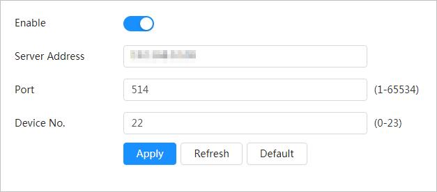
Step 3 Set address, port and device number.
Step 4 Click Apply.
This section introduces the layout of the page and function configuration.
5.1 Live Page
Log in to the web page, and the live view page is displayed..
Pages might vary with different models.
No. Function Description
1 Channel list
2 Image adjustment
4 Live view
5 Live view function bar
5.2 Setting Encode
Displays all channels. You can select the channel as needed and set the stream type.
Adjustment operations in live viewing. For details, see "5.4 Window Adjustment Bar".
Displays the real-time monitoring image.

Functions and operations in live viewing. For details, see Table 5-2
Click , and then select the stream as needed.
● Main Stream: It has large bit stream value and image with high resolution, but also requires large bandwidth. This option can be used for storage and monitoring. For details, see "4.3.3.1 Configuring Encode Parameter".
● Sub Stream: It has small bit stream value and smooth image, and requires less bandwidth. This option is normally used to replace main stream when bandwidth is not enough. For details, see "4.3.3.1 Configuring Encode Parameter".
● means the current stream is main stream; means the current stream is sub stream.
5.3 Live View Function Bar
For the live view function bar, see Table 5-2
Table 5-2 Description of live view function bar
Icon Function Description
Mark Click to select the pen color, and then click to mark a target on the video image.
Force Alarm Display alarm sound state. Click the icon to enable or disable the alarm sound forcibly.
Click the icon to record video, and it will be saved to the configured storage path.
Record
About viewing or configuring storage path, see "4.2 Configuring Local Parameters"
Talk Click the icon to enable or disable the audio take.
5.4 Window Adjustment Bar
5.4.1 Adjustment
This section introduces the adjustment of image. For details, see Table 5-3.
Icon Function Description
AI Rule
5.4.2 Zoom and Focus
Optical Axis Calibration
Window Layout
Click the icon, and then select Enable to display AI rules and detection box; select Disable to stop the display. It is enabled by default.
It is used for adjusting lens position during production. Do not click it.
When view multi-channel image, you can select display layout.
Click Zoom and Focus at the lower-left corner of Live page to adjust focal length to zoom in or out video image; by adjusting focus manually, automatically or within a certain area, you can change image clarity or correct adjusting errors.
The focus would adjust automatically after zooming in or out.
Table 5-4 Description of zoom and focus parameter
Parameter Description
Changes the focal length of the camera to zoom in or out the image.
Zoom Speed
1. Set the speed value. The Zoom Speed is the adjustment range in one click. The larger the value is, the more the image would zoom in or out in one click.

2. Click or hold + or– button, or drag the slider to adjust zoom.
Parameter Description
Adjusts the optical back focal length to make the image clearer.
Focus Speed
1. Set the speed value. The Focus Speed is the adjustment range in one click. The larger the value is, the more the adjustment in one click.

2. Click or hold + or– button, or drag the slider to adjust focus.
Auto Focus Adjusts image clarity automatically.
Do not make any other operation during auto focus process.
Restores focus to default value and corrects errors.
Reset
You can restore the focus if the image has poor clarity or has been zoomed too frequently.
Refresh Get the latest zoom setting of the camera.
Area Focus Focus on the subject of a selected area. Click Area Focus, and then select an area in the image, the camera performs auto focus in that area.
5.4.3 Image Adjustment
Click Image Adjustment at the lower-left corner of Live page, and click + or– button, or drag to adjust image parameters, including brightness, contrast, hue, and saturation.
The adjustment is only available on the web page, and it does not adjust the camera parameters.
● (Brightness adjustment): Adjusts the overall image brightness, and changes the value when the image is too bright or too dark. The bright and dark areas will have equal changes.
● (Contrast adjustment): Changes the value when the image brightness is proper but contrast is not enough.
● (Saturation adjustment): Adjusts the image saturation, this value does not change image brightness.
● (Hue adjustment): Makes the color deeper or lighter. The default value is made by the light sensor, and it is recommended.
Click Reset to restore focus to default value.
You can restore the zoom if the image has poor clarity or has been zoomed too frequently.
5.4.4 PTZ Control
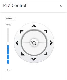
You can rotate the external PTZ device, zoom image, and adjust iris through PTZ control. On the Live page, click the PTZ Control on the lower left corner to adjust the current video screen.
Function Description
Control device toward eight directions, including up, down, left, right, left up, right up, left down and right down. Click , and then select an area in the monitor frame, the PTZ will rotate and zoom quickly to the specified area.
5.4.5 PTZ Function
Speed: The speed value changes device rotate speed. The bigger the value is, the faster the device rotates. For example, the rotation with a speed of 8 is much faster than that of 1.
● PTZ function is available when the camera is connecting with an external PTZ camera.
● You can view the configuration result on the live view of the external PTZ camera. On the Live page, click the PTZ Function on the lower left corner of the page. Before using PTZ function, see "4.5 Configuring PTZ" to configure PTZ function.
Table 5-6 Description of PTZ functions
Parameter Description
Scan
Preset
Tour
Configure the scan number. Click Start, and the device will scan back and forth at a certain speed according to the set boundary. Click Stop to finish scan.
Configure preset number, and then click View to position the device to the corresponding point. The preset contains PTZ's horizontal angle, tilt angle, lens focal length and other parameters.
Configure tour number. Click Start and the device automatically rotates back and forth in the order of the set preset points. Click Stop to finish tour.
Pattern
Pan
Go to
Configure pattern number. Click Start and the device automatically rotates back and forth according to the set operating record. Click Stop to finish pattern. The operation record includes the manual operations that the performed to the PTZ, and the changes in focus and zoom.
Click Start, and then the Camera starts continuous 360° rotation in a horizontal way at a certain speed.
Configure horizontal angle, vertical angel and zoom. Click Go to to pinpoint to a point.
5.5 Real-time Spot Temperature Monitoring
View the real-time temperature of any spot on the image.
Only Cameras with temperature-monitoring function support this function, and the actual product shall prevail.
Click any position of the video image and click. Then the real-time temperature of this spot is displayed.

This section introduces the functions and operations of video playback.
6.1 Playback
6.1.1 Playing Back Video
This section introduces the operation of video playback.
Prerequisites
● This function is available on the camera with SD card.
● Before playing back video, configure record time range, record storage method, record schedule and record control. For details, see "6.2 Setting Record Control", "6.3 Setting Record Plan", and "6.4 Setting Storage".
Procedure
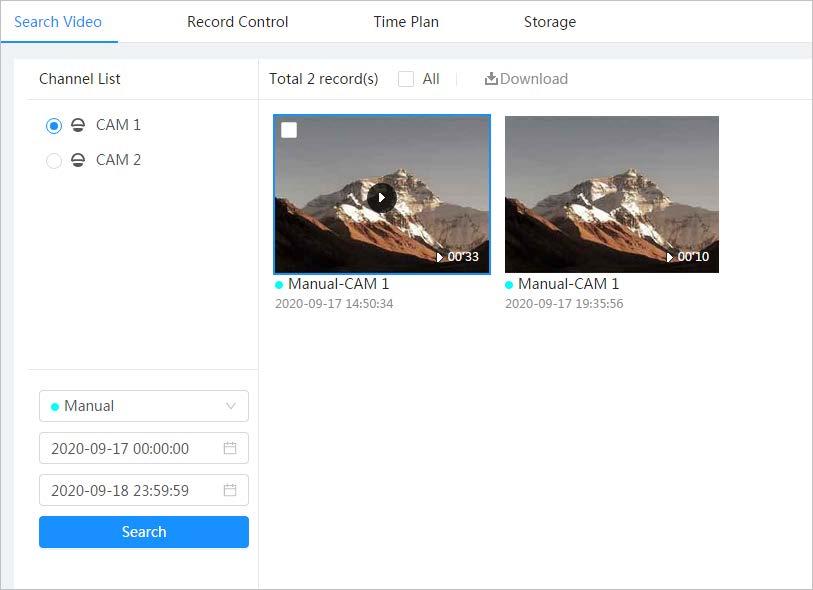
Step 1 Select Record > Search Video
Step 2 Select the channel, the record type, and record time, and then click Search.
● Click All, and select the record type from the drop-down list, you can select from All, General, Event, Alarm, and Manual
When selecting Event as the record type, you can select the specific event types, such as Motion Detection, Video Tamper and Scene Changing.
● The dates with blue dots indicate there are videos recorded on those days.
1 Recorded video list
Displays all searched recorded video files. Click any files to play back it.

Click Back at the upper-left corner to go to the Search Video page
You can zoom video image of the selected area through two operations.
Digital Zoom
● Click the icon, and then select an area in the video image to zoom in; right-click on the image to resume the original size. In zoom in state, drag the image to check other area.
● Click the icon, and then scroll the mouse wheel in the video image to zoom in or out.
Click , and then select Enable to display AI rules and detection box; select Disable to stop the display. It is enabled by default.
AI Rule
AI rules is valid only when you enabled the rule during recording.
Controls playback.
● : Click the icon to play back the previous recorded video in the recorded video list.
● : Click the icon to slow down the playback.
● : Click the icon to stop playing back recorded videos.
Play control bar
The icon changes to , click the icon to play back recorded videos.
● : Click the icon to speed up the playback.
● : Click the icon to play back the next recorded video in the recorded video list.
● : Click the icon to play the next frame.
No Function Description
Controls the sound during playback.
Sound
● : Mute mode.
● : Vocal state. You can adjust the sound.
Click to capture one picture of the current image, and it will be saved to the configured storage path.
Snapshot
About viewing or configuring storage path, see "4.3 Configuring Camera Parameters"
Video clip
Full Screen
3 Progress bar
6.1.2 Clipping Video
Step 1 Click
Click , and clip a certain recorded video and save it. For details, see "6.1.2 Clipping Video"
Click , and the image is displayed in full-screen mode; double-click the image or press Esc button to exit full-screen mode.
Displays the record type and the corresponding period.
● Click any point in the colored area, and the system will play back the recorded video from the selected moment.
● Each record type has its own color, and you can see their relations in Record Type bar
Step 2 Drag the clipping box on the progress bar to select the start time and end time of the target video

Figure 6-3 Clipping video
Step 3 Click OK to download the video.
Step 4 Select the download format and storage path.
Figure 6-4 Clipping video
Step 5 Click Start Download.
The playback stops and the clipped file is saved in the configured storage path. For details of storage path, see "4.3 Configuring Camera Parameters".

6.1.3 Downloading Video
Download videos to a defined path. You can download a single video, or download them in batches.

● Playback and downloading at the same time is not supported.
● Operations might vary with different browsers.
● For details of viewing or setting storage path, see "4.3 Configuring Camera Parameters"
Step 1 Select Record > Search Video
Step 2 Select the channel, the record type, and record time, and the click Search.
Step 3 Select the videos to be downloaded.
● Select at the upper-right corner of each video file to select one or multiple videos.
● Select next to Select All to select all searched videos.
Figure 6-5 Selecting video file
Step 4 Click Download
Step 5 Select the download format and storage path.
Figure 6-6 Downloading video
Step 6 Click Start Download.
The downloaded files are saved in the configured storage path. For details of storage path, see "4.3 Configuring Camera Parameters".
6.2 Setting Record Control
Set parameters such as pack duration, pre-event record, disk full, record mode, and record stream.
Step 1 Click Record in the main page, and then click the Record Control tab.
Figure 6-7 Record control
Step 2 Set parameters.
Table 6-2 Description of record control parameters
Parameter Description
Max Duration
The time for packing each video file.
The time to record the video in advance of a triggered alarm event. For example, if the pre-event record is set to be 5 s, the system saves the recorded video 5 s before the alarm is triggered.
Pre-Record
When an alarm or motion detection links recording, and the recording is not enabled, the system saves the video data within the pre-event record time to the video file.
Record Mode
When you select Manual, the system starts recording; when you select Auto, the system starts recording in the configured time period of record plan.
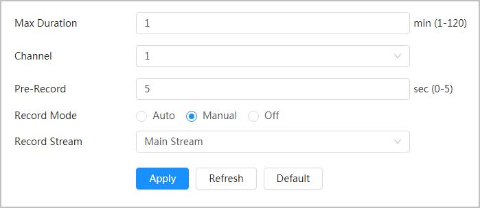
Record Stream Select record stream, including Main Stream and Sub Stream
Step 3 Click Apply.
6.3 Setting Record Plan
After the corresponding alarm type (Normal, Motion, and Alarm) is enabled, the record channel links recording.
Set certain days as holiday, and when the Record is selected in the holiday schedule, the system records video as holiday schedule defined.
Step 1 Click Record on the main page, and then click the Time Plan tab.
Step 2 Set record plan.
Green represents normal record plan (such as timing recording); yellow represents motion record plan (such as recording triggered by intelligent events); red represents alarm record plan (such as recording triggered by alarm-in). Select a record type, such as Normal, and directly press and drag the left mouse button to set the time period for normal record on the timeline.

● Click Copy next to a day, and select the days that you want to copy to in the prompt page, you can copy the configuration to the selected days. Select the Select All check box to select all day to copy the configuration.
● You can set 6 time periods per day.
Step 3 Click Apply.
Step 4 Click Holiday to set holidays.
Step 5 Click to enable the holiday configuration, and select the days that you need to set as holiday

Click Clear to cancel the selection.
When holiday schedule setting is not the same as the general setting, holiday schedule setting is prior to the general setting. For example, with holiday schedule enabled, if the day is holiday, the system snapshots or records as holiday schedule setting; otherwise, the system snapshots or records as general setting.
Step 6 Click OK
6.4 Setting Storage
This section introduces the configuration of the storage method for the recorded videos.
Step 1 Select Record > Storage.
Figure 6-10 Live
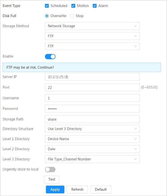
Step 2 Select the storage method that you need for different types of recorded videos.
Table 6-3 Description of storage parameters
Parameter Description
Event Type
Disk Full
Select from Scheduled, Motion Detection and Alarm.
Recording strategy when the disk is full.
● Overwrite: Cyclically overwrite the earliest video when the disk is full.
● Stop: Stop recording when the disk is full.
Select from Local storage and Network storage
● Local storage: Save the recorded videos in the internal SD card.
Storage Method
Step 3
Local storage is displayed only on models that support SD card.
● Network storage: Save the recorded videos in the FTP server or NAS.
Configure network storage parameters. Do this step when selecting Network storage in Storage Method.
Table 6-4 Description of FTP parameters
Parameter Description
Server IP The IP address of the FTP server.
Port The port number of the FTP server.
Username The username to log in to the FTP server.
Password The password to log in to the FTP server.
Storage Path The destination path in the FTP server.
Directory Structure Set the directory structure, and you can select Use Level 1 Directory, Use Level 2 Directory, and Use Level 3 Directory
Level 1 Directory
Level 2 Directory
Level 3 Directory
Set the Level 1 directory name, and you can select from Device name, Device IP, and Custom.
When you select Custom, please enter the custom directory.
Set the Level 2 directory name, and you can select from File Type, Date, File Type_Channel Number, and Custom
When you select Custom, please enter the custom directory.
Parameter Description
Urgently store to local Click , and when the FTP server does not work, all the files are saved to the internal SD card.
● NAS
Parameter Description
Server IP
The IP address of the NAS server.
Storage Path The destination path in the NAS server.
Username When selecting SMB protocol, you are required to enter username and password. Enter them as needed.
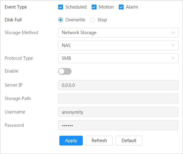
Password
Step 4 Click Apply
This section introduces the related functions and operations of picture playback.
7.1 Playback
7.1.1 Playing Back Picture
This section introduces the operation of picture playback.
Prerequisites
● This function is available on the camera with SD card.
● Before playing back picture, configure snapshot time range, snapshot storage method, snapshot plan. For details, see"7.3 Setting Snapshot Plan"
Procedure
Step 1 Select Record > Picture Query.
Step 2 Select the channel, the snapshot type, and snapshot time, and then click Search
● Click All, and select the record type from the drop-down list, you can select from All, General, Event, and Alarm.
When selecting Event as the snapshot type, you can select the specific event types, such as Motion Detection, Video Tamper and Scene Changing
● The dates with blue dots indicate there are snapshots on those days.
Step 3
Point to the searched picture, and then click to play back the selected picture. The picture playback page is displayed.

Table 7-1 Description of playback page No Function Description
Displays all searched snapshots. Click any files to play back it.
1 Snapshot list
Click Back at the upper-left corner to go to the Picture Query page.
● Click to display the previous snapshot in the snapshot list.
2 Manual display
● Click to display the nest snapshot in the snapshot list.
3 Slide show
4 Full screen
7.1.2 Downloading Picture
Click to display the snapshots list one by one in slide show mode.
Click , and the snapshot is displayed in full-screen mode; double-click the image or press Esc button to exit full-screen mode.
Download pictures to a defined path. You can download a single picture, or download them in batches.
● Operations might vary with different browsers.
● For details of viewing or setting storage path, see "4.3 Configuring Camera Parameters".

Step 1 Select Picture > Picture Query
Step 2 Select the channel, the snapshot type, and snapshot time, and then click Search.
Step 3 Select the pictures to be downloaded.
● Select at the upper-right corner of each picture file to select one or multiple pictures.
● Select next to Select All to select all searched pictures.
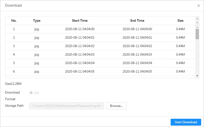
Step 4 Click Download
Step 5 Select the download format and storage path.
Step 6 Click Start Download.
The downloaded pictures are saved in the configured storage path. For details of storage path, see "4.3 Configuring Camera Parameters"
7.2 Setting Snapshot Parameters
Set the snapshot parameters, including type, size, quality and Interval.
Step 1 Select Picture > Snapshot
Step 2 Select the channel and set the parameters.

Parameter Description
You can select from Scheduled and Event.
● Scheduled: Capture images in configured period. For details, see
Type
● Event: Capture images when configured event is triggered, such as Motion Detection, Video Tamper and Scene Changing.
Make sure that you have enable the corresponding event detection and the snapshot function.
Size
It is same with the resolution of the main stream.
Quality Set the quality of the snapshot. The higher the value, the better the quality.
Interval Set the frequency of snapshot. You can select Custom to set the frequency as needed.
Step 3 Click Apply.
7.3 Setting Snapshot Plan
According to the configured snapshot plan, the system enables or disables snapshot at corresponding time. For detailed operation, see "6.3 Setting Record Plan".

7.4 Setting Storage
Set the storage method for the snapshot. For detailed operation, see "6.4 Setting Storage".
8.1 Configuring IVS
This section introduces the requirements of scene selection, global configuration and rule configuration.
Requirements of scene selection:
● The target should occupy no more than 10% of the whole image.
● The pixel of the target should be no less than 10×10; the pixel of abandoned object should be no less than 15×15 (CIF image); the width and height of the target should be no more than 1/3 that of the image; it is recommended that the height of the target should be set to 10% of the image height.
● The brightness difference of the target and the background should be no less than 10 gray levels.
● The target should be continuously present in the image for no less than 2 seconds, and the moving distance should be larger its width and no less than 15 pixels (CIF image) at the same time.
● Try to reduce the scene complexity as much as condition allowed; it is not recommended to use Intelligence Behavior Analysis in scenes with intensive targets, changing lighting conditions or small difference between target temperature and scene temperature.
● For thermal channel, try not to monitor scenes with glass. For visual channel, try not to monitor: scenes with reflective surfaces such as glass, bright ground or water; scenes that disturbed by tree branches, shadows or winged insects; scenes that against light or under direct light exposure. Control image proportion of objects that are with high relative ambient temperature.
8.1.1 Global Configuration
Configure global rules for IVS. You can draw the detection area and exclusion areas. When the configured rules is triggered in the detection areas (out of the exclusion areas), an alarm will be triggered. For the thermal channel, you can also configure the sensitivity.
Step 1 Select AI > AI Config > Smart Plan.
Step 2 Click next to IVS to enable IVS of the corresponding channel.
● Channel 1 is visible channel.
● Channel 2 is thermal channel.
Step 3 Click Next.
Step 4 Click the Global Config tab.
Step 5 Select the channel.
● Select 1 in Channel to set the global parameters of visible channel.
● Select 2 in Channel to set the global parameters of thermal channel.
Step 6 Add a detection area or an exclusion area.
1) Click to draw a detected area on surveillance image. The whole image is the detection area by default, drag corners of the detection area to adjust the area.
2) Click to draw an exclusion area on surveillance image. Right-click to finish drawing.
● Select the exclusion area, and then click to delete the exclusion area.
● An exclusion area takes effect only when it has been drawn in the detection area
● Multiple exclusion areas can be drawn in the detected area.
Step 7 (Optional) Configure the global sensitivity. The higher the value, the easier the actions can be detected.
This step is only available on the thermal channel.
Step 8 Click Apply
8.1.2 Rule Configuration
Set rule for IVS, including tripwire and intrusion.
Prerequisites
You have finished global configuration. For details, see "8.1.1 Global Configuration"
Background Information
For the functions and applications of the rules, see Table 8-1. This section uses configuring tripwire as an example.
Rule Description
Tripwire
When the target crosses tripwire from the defined motion direction, an alarm is triggered, and then the system performs configured alarm linkages.
Applicable Scene
Intrusion
Procedure
When the target enters, leaves, or appears in the detection area, an alarm is triggered, and the system performs configured alarm linkages.
Step 1 Select AI > AI Config > Smart Plan.
Scenes with sparse targets and no occlusion among targets, such as the perimeter protection of unattended area.
Step 2 Click next to IVS to enable IVS of the corresponding channel, and then click Next.
Step 3 Click the Rule Config tab.
Step 4 Click Add Rule, and then select Tripwire from the drop-down list. Click the name, and you can edit the rule name; the rule is enabled by default.
Step 5 Click to draw rule line in the image. Right-click to finish drawing. For requirements of drawing rules, see Table 8-2. After drawing rules, drag corners of the detection area or detection line to adjust the area range.
Rule Description
Tripwire
Draw a detection line.
Draw a detection area.
Intrusion
● During the detection of abandoned object, the alarm is also triggered if pedestrian or vehicle stays for a long time. If the abandoned object is smaller than pedestrian and vehicle, set the target size to filter pedestrian and vehicle or properly extend the duration to avoid false alarm triggered by transient staying of pedestrian.
● During the detection of crowd gathering, false alarm might be triggered by low installation height, large percentage of single person in an image or obvious target occlusion, continuous shaking of the camera, shaking of leaves and tree shade, frequent opening or closing of retractable door, or dense traffic or people flow.

Step 6 (Optional) Click other icons at the right side of the image to filter targets in the image.
● Click to draw the minimum size of the target, and click to draw the maximum size of the target. Only when the target size is between the maximum size and the minimum size, can the alarm be triggered.
● Click , and then press and hold the left mouse button to draw a rectangle, the pixel size is displayed.
● Click to delete the detection line.
Step 7 Configure rule parameters for IVS.
Parameter Description
Set the direction of rule detection.
Direction
● When setting tripwire, select A->B, B->A, or A<->B
● When setting intrusion, select Enter, Exit, or Both.
Action When setting intrusion action, select Appears or Cross
Click to enable this function.
Target Filter
● When you select Human as the alarm target, an alarm will be triggered when the system detects that persons trigger the rule.
● When you select Motor Vehicle as the alarm target, alarm will be triggered when the system detects that vehicle triggers the rule.
● For abandoned object, the duration is the shortest time for triggering an alarm after an object is abandoned.
Duration
● For missing object, the duration is the shortest time for triggering an alarm after an object is missing.
● For parking detection, crowd gathering, or loitering detection, the duration is the shortest time for triggering an alarm after an object appears in the area.
Sensitivity
● For fast moving, sensitivity is related to the triggering speed. Lower sensitivity requires faster moving speed to trigger the alarm.
● For crowd gathering, sensitivity is related to the alarm triggering time. It is easier to trigger the alarm with higher sensitivity.
Step 8 Set arming periods and alarm linkage action. For details, see "4.6.1.2 Alarm Linkage".
Click + Event Linkage to set the linkage action.

Step 9 Click Apply
To view alarm information on the alarm subscription tab, you need to subscribe relevant alarm event. For details, see "4.6.1.3.2 Subscribing Alarm Information"
8.2 Configuring Call Detection
Configure the rule for calling in the visible channel. When a call action is detected, an alarm is triggered., and the system performs linkages such as recording, alarm output, sending email, and snapshot.
8.2.1 Global Configuration
Configure global rules for call detection. You can draw the detection area and exclusion areas. When the configured rules is triggered in the detection areas (out of the exclusion areas), an alarm will be triggered.
Call detection and IVS cannot be enabled at the same time.
Step 1 Select AI > AI Config > Smart Plan.
Step 2 Click next to Call Detection in CAM 1.
Step 3 Click Next
Step 4 Click the Global Config tab.
Step 5 Add a detection area or an exclusion area.
1) Click to draw a detected area on surveillance image. The whole image is the detection area by default, drag corners of the detection area to adjust the area.
2) Click to draw an exclusion area on surveillance image. Right-click to finish drawing.
● Select the exclusion area, and then click to delete the exclusion area.
● An exclusion area takes effect only when it has been drawn in the detection area
● Multiple exclusion areas can be drawn in the detected area.
Step 6 Click Apply
8.2.2 Rule Configuration
Configure the rule for call detection, such as drawing rules and set linkage actions.
Prerequisites
You have finished global configuration. For details, see "8.2.1 Global Configuration"
Procedure
Step 1 Select AI > AI Config > Smart Plan.
Step 2 Click next to Call Detection to enable the call detection function.
Step 3 Click Next
Step 4 Click the Rule Config tab.
Step 5 Click to enable the call detection function.
Step 6 Click to draw a detected area on surveillance image. The whole image is the detection area by default, drag corners of the detection area to adjust the area.
Step 7 (Optional) Click other icons at the right side of the image to filter targets in the image.
● Click to draw the minimum size of the target, and click to draw the maximum size of the target. Only when the target size is between the maximum size and the minimum size, can the alarm be triggered.
Step 8 Set the interval and sensitivity.
● Interval: The time that calling behavior lasts. When the camera detects the calling time beyond the configured value, an alarm is triggered.
● Sensitivity: The larger the value is, the more sensitive the call detection is. However, setting the value too large might cause false alarm.
Step 9 Set arming periods and alarm linkage action. For details, see "4.6.1.2 Alarm Linkage".
Click + Event Linkage to set the linkage action.

Step 10 Click Apply.
To view alarm information on the alarm subscription tab, you need to subscribe relevant alarm event. For details, see "4.6.1.3.2 Subscribing Alarm Information".
8.3 Configuring Smoking Detection
8.3.1 Global Configuration
Configure global rules for smoking detection. You can draw the detection area and exclusion areas. When the configured rules is triggered in the detection areas (out of the exclusion areas), an alarm will be triggered.
Background Information
Smoking detection and IVS cannot be enabled at the same time.
Procedure
Step 1 Select AI > AI Config > Smart Plan
Step 2 Click next to Smoking Detection in CAM 2
Step 3 Click Next.
Step 4 Click the Global Config tab.
Step 5 Add a detection area or an exclusion area.
1) Click to draw a detected area on surveillance image. The whole image is the detection area by default, drag corners of the detection area to adjust the area.
2) Click to draw an exclusion area on surveillance image. Right-click to finish drawing.
● Select the exclusion area, and then click to delete the exclusion area.
● An exclusion area takes effect only when it has been drawn in the detection area
● Multiple exclusion areas can be drawn in the detected area.
Step 6 Click Apply.
8.3.2 Rule Configuration
Configure the rule for smoking detection, such as drawing rules and set linkage actions.
Prerequisites
You have finished global configuration. For details, see "8.2.1 Global Configuration".
Procedure
Step 1 Select AI > AI Config > Smart Plan
Step 2 Click next to Smoking Detection to enable the call detection function.
Step 3 Click Next
Step 4 Click the Rule Config tab.
Step 5 Click to enable the call detection function.
Step 6 Click to draw a detected area on surveillance image. The whole image is the detection area by default, drag corners of the detection area to adjust the area.
Step 7 (Optional) Click other icons at the right side of the image to filter targets in the image.
● Click to draw the minimum size of the target, and click to draw the maximum size of the target. Only when the target size is between the maximum size and the minimum size, can the alarm be triggered.
Step 8 Set the interval and sensitivity.
● Interval: The time that smoking behavior lasts. When the camera detects the smoking time beyond the configured value, an alarm is triggered.
● Sensitivity: The larger the value is, the more sensitive the smoking detection is. However, setting the value too large might cause false alarm.
Step 9 Set arming periods and alarm linkage action. For details, see "4.6.1.2 Alarm Linkage". Click + Event Linkage to set the linkage action.
Step 10 Click Apply.
To view alarm information on the alarm subscription tab, you need to subscribe relevant alarm event. For details, see "4.6.1.3.2 Subscribing Alarm Information".
8.4 Configuring Cold Hot Spot
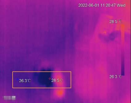
After enabling Cold Hot Spot, spot with the highest temperature and spot with the lowest temperature are displayed with different colors.
Step 1 Select AI > AI Config > Smart Thermal.
Step 2 Click Edit in Cold Hot Spot
Step 3 Click to enable the function.
Step 4 Select the hot spot color and cold spot color.
● Auto: The hot spot color is red, and the cold spot color is blue by default.
● Manual: You can customized the colors for the hot spot and cold spot.
Step 5 Click Apply
8.5 Configuring Fire Warning
Configure the fire warning, including fire warning rule, smoke detection rule, and smoke and fire detection mode.
8.5.1 Configuring Fire Warning Rule
When the camera detects a fire, an alarm is triggered and then system performs linkages such as recording, alarm output, sending email, audio, alarm light, and snapshot.
Step 1 Select AI > AI Config > Smart Thermal.
Step 2 Click Edit in Fire
Step 3 Click the Fire tab.
Step 4 Click to enable the function.
Step 5 Select the fire warning mode as needed.
Step 6 Draw the detection area, and configure the sensitivity. Click then color in , set the area name, and then drag the mouse on the image.
● The higher the sensitivity is, the easier a fire will be triggered.
● Th whole image is the detection area by default. You can draw multiple detection areas.
Step 7 Set the anti-dither period.
The camera only records one alarm event during the anti-dither period.
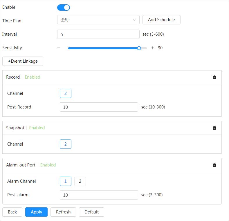
Step 8 Set arming periods and alarm linkage action. For details, see "4.6.1.2 Alarm Linkage".
Click + Event Linkage to set the linkage action.

Step 9 Click Apply
To view alarm information on the alarm subscription tab, you need to subscribe relevant alarm event. For details, see "4.6.1.3.2 Subscribing Alarm Information".
8.5.2 Configuring Smoke Detection Rule
After configuring smoke detection rule, when the visible channel detects smoke, an alarm is triggered, and the system performs linkages such as recording, alarm output, sending email, audio, alarm light, and snapshot.
Step 1 Select AI > AI Config > Smart Thermal
Step 2 Click Edit in Fire.
Step 3 Click the Smoke Detection tab.
Step 4 Click to enable the function.
Step 5 Click Add, draw the detection area on the image, and then set eh sensitivity. When the camera detects smoke in the detection areas, the target box flashes, which will stop the PTZ operation
● Only one detection area can be added.
● The larger the value is, the higher the sensitivity will be. The default value is recommended.
Step 6 Configure the advanced parameters.

Table 8-4
Parameters
Min Duration
Repeat Alarm Time
Configure advanced parameters
Description
When the smoke lasts longer than the configured value, an alarm is triggered.
The system will filter the repetitive alarms, and only one alarm will be triggered during the configured period.
Target Filter Threshold The larger the value is, the easier the static smoke will be detected.
False Alarm Filter Enable this function , filter the objects causing false alarm, such as water drop and stains.
Step 7 Set arming periods and alarm linkage action. For details, see "4.6.1.2 Alarm Linkage".
Click + Event Linkage to set the linkage action.
Step 8 Click Apply.
To view alarm information on the alarm subscription tab, you need to subscribe relevant alarm event. For details, see "4.6.1.3.2 Subscribing Alarm Information".
8.5.3 Configuring Smoke and Fire Detection Mode
Step 1 Select AI > AI Config > Smart Thermal
Step 2 Click Edit in Fire.
Step 3 Click the Smoke and Fire Detection Mode tab.
Figure 8-9 Smoke and Fire Detection Mode
Parameter
Fire or smoke
Fire Only
Smoke Only
Fire and Smoke
Table 8-5 Smoke and fire detection mode
Description
When the visible channel detects smoke or the thermal channel detects heat, an alarm will be triggered.
When the thermal channel detects heat, an alarm will be triggered.
When the visible channel detects smoke, an alarm will be triggered.
When the visible channel detects smoke and the thermal channel detects heat at the same time, an alarm will be triggered.
● Fire or smoke: Enable heat detection and smoke detection at the same time. When either of the two is triggered, an alarm is triggered.
● Fire only: When heat detection is triggered, an alarm is triggered.
● Smoke only: When smoke detection is triggered, an alarm is triggered.
● Fire and smoke: Enable heat detection and smoke detection at the same time. When both of the two are triggered, an alarm is triggered.
Step 4 Click Apply
To view alarm information on the alarm subscription tab, you need to subscribe relevant alarm event. For details, see "4.6.1.3.2 Subscribing Alarm Information"
8.6 Configuring PIP
Overlay the thermal image on the visible image.
Step 1 Select AI > AI Config > Smart Thermal.
Step 2 Click Edit in PIP.
Step 3 Click to enable the function.

Step 4 Click the blue box on the image, and drag it to adjust the box. You can drag any corner of the box to adjust the size.
Step 5 Click Apply
8.7 Configuring Thermal Map Acquisition
Grasp temperature of every pixel on thermal images, and you can export the heat map.
Step 1 Select AI > AI Config > Smart Thermal.
Step 2 Click Edit in Thermal Map Acquisition
Figure 8-11 Thermal map acquisition
Step 3 Configure the parameters.
● Frame: The frame of the thermal map that you can acquire.
● Get Mode
◇ Single Frame: Acquires thermal map by single frame. There is interval between the previous frame and next frame.
◇ Continuous: Acquires thermal map by continuous frame. There is no interval between the previous frame and next frame.
Step 4 Click Export Heat Map

Thermal map files will be saved under the path that you have configured. For details, see "4.2 Configuring Local Parameters"


