3 minute read
MORE BENCH TALK –LATHE STOPS & GAUGES
to move the cam up and down.
A small retaining plate needs to be added, to prevent the nut from rotating when in the middle of its travel (Photo 38). The size of this is not especially critical, so long as it covers the majority, or all, of the slot in which the nut travels.
Advertisement
Its attachment method is also non-critical; we tig-welded our plate onto the cam, but silver-soldering or the use of a small tapped-hole and retaining bolt would both do equally as well. Even Loctite might do, as there is (or should be, if the threads are clean and made correctly) very little force on this plate. The plate should be placed on the rear of the cam, as it will be fitted on the tender, so it will not be seen from the outside.
To attach the brake cam to the brake-pivot rod, we originally planned to use a roll-pin, and the holes for this are shown in Figure 31. When we came to test-assemble the tender, prior to disassembly and painting, we decided it was probably easier to use a grub-screw (Photo 39), with a suitable indent drilled into the rod when this cam is set at the appropriate angle relative to the other cam (the brakepull cam). This makes brake adjustment relatively simple and will be discussed further later in the build.
Four brake hangers are required, all being identical (Figure 33 and Photo 40). Again, a little filing may be required, notably of the ‘entrance’ to the circular part in which the brake cross-bar inserts. This will be discussed in more detail below.
Finally we need brake-hanger spacers and mounting bolts. The brake hangers, and hence the brake shoes, need to be offset a significant distance from the inner sides of the frames. They also need to be held rigidly, as this offset distance imparts quite a leverage when the brakes are tightly applied.
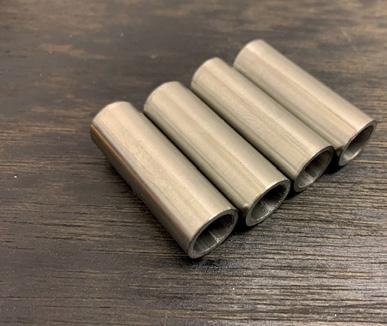
To achieve the spacing and strength, the design uses M10 bolts as the pivots for the brake hangers and steel tube to form the spacers (Figure 34 and Photo 41). We used stainlesssteel for both the bolts and the tube, though this is probably overkill.
The precise configuration will be explained in greater detail when it comes to the assembly of the tender; for the present, it is sufficient to make the spacers from 12mm outsidediameter, 10mm inside-diameter, (stainless) steel pipe. The only operation therefore required is to part-off the pipe to the correct length (4-off of these parts are required). This is a very satisfying job, as four completed parts can be created in a matter of minutes – an important consideration where impatient young apprentices are concerned...
PHOTO 39: Brake cam complete with grub-screw.
PHOTO 40: Brake hanger.
PHOTO 41: Brake-hanger spacers made from steel tube.
Next month – brake blocks and handbrake levers.
EIM

MORE BENCH TALK Stops and gauges
A couple of lathe additions make repetitive machining slightly less of a chore...
BY HARRY BILLMORE
Irecently had to machine 12 bearing carriers for the carriage bogies at the Fairbourne Miniature railway – the lathe I have does is not yet set up with a digital read out so to make my life easier I added a couple of extras on the lathe.
One is a simple bed stop that clamps onto the lathe bed to halt the carriage at a set position. The other is a dial indicator – this is held on a magnetic base on the carriage with the pointer contacting the cross slide.
I carefully machined the first bearing carrier to get the final set positions correct, zeroed the dial indicator, then proceeded to machine the rest of the carriers with minimal fuss and maximum accuracy. EIM
■ Do YOU have a tip or a comment to share with fellow readers in Bench Talk? Send to the editorial address on page 3 . RIGHT: A stop on the lathe bed and a dial indicator on the cross slide gives repeatable accuracy when one is machining multiple items.


