31 minute read
ELECTRONICS – A TWO-TONE LOCO HORN
ELECTRONIC ENGINEERING A ‘cheap and cheerful’ t wo-tone loco horn
Julian provides a novice’s guide to electronics programming with an eff ective outcome.
Advertisement
BY JULIAN HARRISON
Ihave recently been involved with the challenge of designing and building an electric locomotive as an entry level project for any budding builders and to encourage new members to our club. When we went to the track to test an early trial build we had to fit a horn to comply with the club rules.
We had already decided to use some cheap twin-tone 12-volt car horns bought on an online auction site as these kept the cost down which was part of the loco project. These horns come as a twin pack. Each has a slightly different tone and they are designed to be sounded together. As they are so loud we only planned to use one on the loco with just a push-button and a relay to operate it.
While testing the early version of our loco I had a drive of another member’s engine. He had used two horns of some sort wired to a three-way on/off/on switch. This gives the option to sound the horns independently or as a manual two-tone by switching one on then the other on in an approximation of a British twin-tone train horn. This system was used on many full-size locomotives. I decided at the time that I wanted an automatic twin-tone horn so set about designing the simplest and cheapest one I could.
My plan was that it would work with just the quick press of a button. A switch should be included to allow the driver’s selection of either a short blast or a long blast. We could have gone to one of the model companies that offer various sound systems at various prices but where is the fun in that? This horn system is very simple to build and has a minimum number of parts. With judicious purchasing of said parts it is possible to complete this project for under £25.
1
“This horn system is very simple to build and has a minimum number of parts. With judicious purchasing it is possible to complete this project for less than £25...” Versatile product
I have previously used Arduino Microprocessor boards in several projects including digital readout systems for my milling machines. They are a very versatile, cheap and small board that is suited to this project. There are many different Arduino boards available. They offer different speeds, memory, processors, and physical sizes to suit various different projects.
I used the Arduino Uno because it is probably the cheapest and most common and because I have several in stock. This board is about 70mm by 50mm so has a reasonable footprint. The Uno has far more speed and memory than we need so there is no need to use the more advanced, and therefore, more expensive models. It can handle a 12v supply and provides its own 3.2v and 5v switching voltages. It has a 2.5mm socket to connect a stabilised 12v supply and a USB socket for programming it.
Photo 1 shows a typical Arduino Uno. Don’t worry about all the different connector blocks. Some have a lot and some have the bare minimum of standard pins. These standard pins are all we need so ignore all the others.
These boards can be bought very cheaply often for less than a fiver from the online auction sites. Arduinos are very capable but have one big drawback. They can only supply about 40ma to each pin which is only enough for an LED, relay or electronic sensor. They cannot directly supply a car horn which needs up to 10 amps so we need a relay for each horn.
Shields can be obtained with relays on them specifically for this purpose. A shield is a board that is the same size as the Arduino board and that plugs directly into the pins of the Arduino. There are many shields available including relay boards, digital displays, switch boards, communication boards and many others. They are normally far more expensive than the Arduino boards they are built to fit but if you want the most straightforward way to build this project they are the route to take.
Many of the full-sized shields only have 3amp relays which are not good enough for the horns. There are some 10amp available but be certain what you are buying.
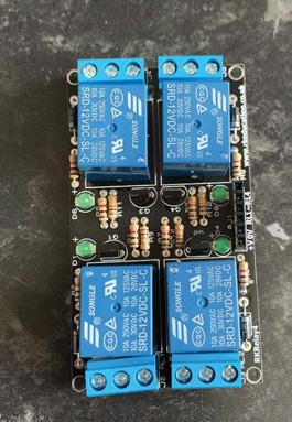
While you are searching for relay shields you will see various others that need to be wired to the Arduino rather than plugged directly in. These are just as good and are what I used. Photo 2 shows my completed self-assembly board complete with four 10amp relays. For the horns you only need two relays but I bought the four-relay board as it was cheaper. The others could be used for other tasks if you decide to learn to write the program yourself, otherwise just ignore them.
2

Build it yourself
Also be aware that many of these are sold as self-assembly kits. If you are happy with this they are a lot cheaper.
If you are not willing or able to assemble one make sure you buy the ready-assembled units.
The other board you will need is a small piece of Veroboard. This is a simple electronic building board that can be used for electronic projects rather than printed circuit boards. It is very cheap and easy to use.
Veroboard is a thin board drilled with small holes in a grid. One side is plain board and the other side has strips of copper bonded on connecting lines of holes. Photo 3 shows a piece of board from which the smaller piece I needed was cut from. Score with a Stanley knife and snap is the easiest way to divide it. For this project we need four resistors and this was the easiest way to connect them – we only need a small piece measuring about 40mm square.
Other items required are a non-locking push button of your choice, a single-pole double-throw switch of your choice that has two positions (often described as ‘on/on’), four 10k resistors and some thin single-core 1mm electronic wire. If you want to you can fit the finished assembly into a project box but this is up to you. I just glued them together with the Uno on the bottom and the Veroboard on top – hot glue is ideal for this purpose but other adhesives will work. Various pins on the Arduino are used to read the switch and button and to activate the relays.
Logical process
Before we start building let’s sort out some logic. Logic is what micro processors work on and, though it doesn’t always seem like it, so do our brains. In this project the Arduino will just read or write to and from some of its pins. Making the sound using the two horns is just a case of switching them on and off in a set order, which can be written like this:
l When the button is pressed check the switch position. l Is the switch set to long or short? Remember the answer. l Switch on horn one. l Keep the horn sounding for a set time dependent on the switch position (long or short). l Turn on horn two. l Turn off horn one. l Keep horn two sounding for a short time again dependent on the position of the switch. l Turn off horn two. l Wait for the button to be pressed again.
The instructions are written into a program which for Arduino is called a ‘Sketch’. Both the delays are written into the Sketch but are dependent on the position of the switch. One position gives a very short blast while the other gives a longer blast. If you find that the blasts are not as you want them they are easy to change and reprogram once built. Writing the required actions out in their order helps with the sketch design. After setting the pins on the Arduino we just have to use the correct commands to turn the horns on and off.
Before we can write the Sketch we need to download a program called ‘Arduino IDE’. The Arduino Integrated Development Environment (https://docs.arduino.cc/software/ ide-v1) contains a text editor for writing the code, a message area, a toolbar with buttons for common functions and a series of further menus. It connects the computer to the Arduino board to upload programs (Sketches).
The Arduino IDE can be easily downloaded and installed on any computer. It is completely free and fully working. It is a text editor that you type the programming into and then the IDE verifies the code and tells you if anything is wrong. If all is okay it will load the program into the Arduino board plugged into your USB port. I will describe the programming fully here so you gain some understanding of how it works. Hopefully this will inspire some of you to learn about Arduinos and use them for other projects. There are many very helpful sites and forums where you can get help or information.
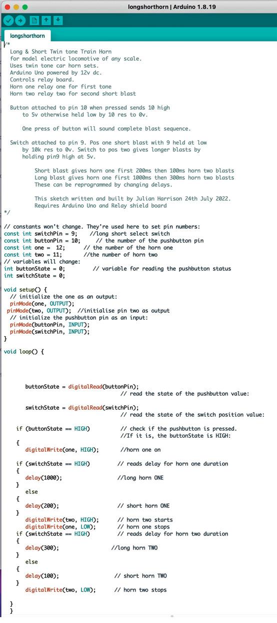
The sketch splits into three sections. Figure 1 is a copy of my sketch. In the first part we tell the sketch which pins we are using and what we want to name them. Pins 12 and 11 are called ‘one’ and ‘two’ respectively. I have chosen to use these pins for my own convenience. If you have purchased a shield that plugs directly onto the Uno board you will need to change these pin numbers to the ones used to control the relays on the shield.
We could call them pin 12 and pin 11 but I find names make it easier to remember what they do. Pin 10 is named ‘buttonPin’ and pin 9 is named ‘switchPin’. These are known as constants because the names will not change throughout the program.
We also name a couple of variables that hold the readings of the button and switch. These are virtual placeholders within the processors memory and just hold the current value of the button and switch pins for use in the program. They change so are declared as variables. Because they are not constant the command is slightly different. Declarations are a part of the programming that tells the processor which pins it will be using.
We use the command ‘const int’ to set the constants so we have:

PHOTO 1: A bare Arduino Uno board.
PHOTO 2: The author ’s assembled relay shield
PHOTO 3: A typical piece of Veroboard, used for making up circuits.
All photos and diagrams by the author
3
const int switchPin = 9; const int buttonPin = 10; const int one = 12; const int two = 11;
The variables are set by:int buttonState = 0; int switchState = 0;
They are set to zero when the Arduino first starts up and will change as the sketch progresses. These commands have both declared which pins we are using and named them at the same time. All other pins on the Arduino will be ignored as we have not declared or allocated them.
Colour coded
As you type commands in they will change colour when they are correct – you do not need to colour the text as it is automatic. You must remember the spaces between words and the semicolon at the end of every line. The most common programming faults are missing the semicolon, missing curly brackets or not using capitals when required as everything is case sensitive. Capitals are rarely used at the start of a word but are used part way through the command so please be careful what you type.
The next section is called ‘void setup’ and will always start with a left-hand curly bracket ‘{’. In this section we do what the title says we ‘set up’ the pins. This sets them to input or output. The horns need outputs so voltage f lows out to switch the relays on: pinMode(one, OUTPUT ); pinMode(two, OUTPUT ); s
The button and switch pins accept an input so need to be set as such: pinMode(buttonPin, INPUT ); pinMode(switchPin, INPUT );
Again when you type everything correctly some words will change colour. You will notice in my sketch most lines have a comment after the command. The comment is anything after the ‘//’. The program knows this is just comments for mere humans to keep track of things and it will ignore them. After all the processor knows what to do because we have told it and it does not need to know why. This section ends with a right-hand curly bracket. These curly brackets enclose related parts of the program.
The third section of the sketch is where the action happens. It is called the ‘void loop’ and in this sketch will check the button, check the switch, turn the horns on and off and will use the corresponding delays. It will then loop back to the beginning of this section and wait to do it all again.
The previous two sections will only run when the Arduino is powered on. They are just the initial settings required to set up the board and make it ready to run the rest of the sketch. This third section will ‘loop’ whenever it is triggered by the pressing of the horn button. It will, in this sketch, run straight through the commands in the order they are written and then wait.
If you choose to learn more about programming these boards you will find large ones that take many convoluted paths to complete the end of the loop. Remembering back to when we listed the f low of what needs to happen for the twin-tone horn to sound you will see a remarkable similarity to the void loop programming but using some commands – ‘digitalWrite’ turns pins on or off, ‘digitalRead’ reads the state of pins and ‘delay’ tells the program how many microseconds to pause for. These are action commands that demand a response, for example switching on or off.
Questions, questions
The power used to supply the button and the switch and to energise the relays is all supplied by the board itself at, in this case, five volts. Because the length of the delay depends upon the position of the switch there are also some questions to be asked so ‘if ’ and ‘else’ are used.
Because the processor works on logic the digital pins we are using only have two states. Low is zero volts. High is supposed to be, in this case, five volts but really is anything just above zero.
The four resistors on the Veroboard connect these four pins to 0v and act as what are known as hold-down resistors. When the pins are low the resistors make sure that they stay low. If they were not held down they could f loat above zero from any stray voltage in the atmosphere or the loco. It could cause false readings
FIGURE 1: The complete Arduino sketch as it appeared on Julian’s computer screen. FIGURE 1
and sound the horns when you do not want to. When the program sends the pins high it will react correctly because the resistors are big enough to stop a short circuit happening. void loop( ) { will normally already be present in the IDE text editor. If it has not got one insert a left curly bracket. This tells the sketch to execute everything from this curly bracket until its mate at the end. The first two lines set the variables depending on the state of the input pins. ButtonState will by default be low unless the button is pressed. SwitchState will depend upon the position of the long/short switch.
While in standby the variables are constantly monitored by the processor and the loop will start only when the buttonState variable goes high which is when the driver presses the button to sound the horn.
Helpful names
It can be seen from these commands why we named the pins and variables. It makes them easier to understand. We firstly need to tell the processor which pins to read for each variable. buttonState = digitalRead(buttonPin); switchState = digitalRead(switchPin);
Next we ask if the button has been pressed. ‘If ’ is one of the most-used commands in the Arduino language. This is true of virtually all computer programming languages. The first ‘if ’ is the point at which the button is pressed and the processor realises that the button variable has gone high. It will not react to low only to high because we have two equals signs. The double equals forces it to only trigger on high and nothing else.
If (buttonState == HIGH); {
This is followed by a left curly bracket to tell the sketch to run everything between it and its mate which will be located near the end of the sketch.
The easiest way to understand curly brackets is to regard them as boxes which contain some commands and some contain other boxes. This gets very confusing because many commands require their own sets of curly brackets and they can get quite hard to keep track of.
Luckily the IDE program helps us out in two ways. If you click your mouse on the right of a curly bracket it will then highlight its companion. When you verify the programming to check it the fault will show which one is missing.
The next command switches on horn one by writing the pin high
digitalWrite(one, HIGH);
Next we set the delay from the switch position. Because we have read the state of the switch we can tell the program which delay to use but we don’t need to tell it too much. We are saying if the state is high(5v) use one delay time, else if it is not use a different delay. This is how the if/else combination works.
These commands match our human decision-making processes. A simple example is – If you want a hot drink switch the kettle on. If you want any other drink don’t switch the kettle on. It is not a case of switch it off for any other drink merely just don’t switch it on – there is a difference.
Our switch in this project will supply 5v to the pin to send it high and use the longer delay otherwise the delay will be shorter because it will stay low. Delay is set by the number of microseconds in the brackets. One thousand microseconds is a onesecond delay.
Notice the curly bracket in this sequence. They surround the delay commands. The commands surrounded by sets of curly brackets will only be run by the previous command. The longer delay is the only thing that ‘if ’ can run while the short delay can only be run by the ‘else’ command.
if (switchState == HIGH); { delay(1000); } else { delay(200); }
Next we need to turn on horn two and then turn off horn one. I have allowed this very small overlap so the two horns blend together. If we switched off horn one then switched on horn two there would be a miniscule pause, which would give an abrupt change.
The noise made by full-size loco horns blends together because it takes a moment for the first horn to stop sounding – this sketch tries to replicate that blending. If we want a longer overlap we could add a delay between them but at present I have chosen not to do so.
digitalWrite(two, HIGH); digitalWrite(one, LOW);
We now need the smaller delays for horn two. This is an exact copy of the previous ‘if ’ and ‘else’ commands but with shorter delays.
if (switchState == HIGH); { delay(300); } else { delay(100); } digitalWrite(two, LOW);
Horn two is turned off after the delay. The values used in this Sketch, as written, will give a long blast of 1000 microseconds (1 Second) and 300 microseconds (three tenths of a second) for horns one and two respectively. The short blast is three tenths and two tenths of a second respectively. I have used these settings for the past few weeks and they seem to be about right. Just over a second does not sound much but when the horns are sounding it feels longer. It is a nice short warning blast to get people’s attention.
The sketch finishes with two right curly brackets. The first is the mate to the one placed after the button has gone high. The last closes the entire void loop section. This signifies the end of the sketch and once it is reached the program will go back to check the button again.
Curly brackets are probably the hardest thing to understand in programming an Arduino sketch. Fortunately the IDE will help us with them. If any are missing they will show up in the verification process.
Your sketch needs to be saved somewhere on your computer. It is a requirement that they are saved inside their own folder. They can be saved onto the desktop but will not be able to be opened by the Arduino IDE until they are in their own folder.
If you double-click the icon to open the file it will make a folder for you before it opens the Sketch. You can make a folder and save into that if you wish. The folder can be anywhere convenient including on the desktop. I usually give it the same name as the sketch, in this case ‘longshorthorn’.
At the top of the IDE window there are five buttons. The round tick is verify and the right arrow is upload. The three square ones are new sketch, open existing sketch and save sketch. Rolling your mouse over them opens a label for each one. Once a sketch is saved it can easily be opened by double-clicking the file and it will open and run the IDE.
To check your programming click the round tick button. The IDE will check the sketch and highlight any faults one at a time. It will show the first one in an orange panel at the bottom of the window and will take you to the faulty line for you to correct it. Once corrected click verify again s
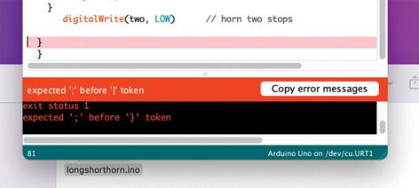
FIGURE 2 FIGURE 3
and it will take you to the next fault.
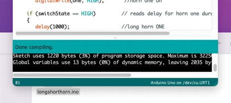
Repeat until all faults are cleared – a large majority of them will be typos. Figure 2 shows a fault I created to show this. I have removed the semicolon from the ‘digitalWrite’ command that turns off horn two. The error message in the orange box shows you what it is expecting on the line before the pink highlighted line. Once all faults are sorted it will show you the size of the program and tell you it has ‘Done compiling’. Figure 3 shows the errors all corrected.
All that remains now in this part is to upload the sketch to your Arduino board. Plug a suitable cable into the USB port on the Arduino and a USB port on your computer. This cable will power the Arduino which will light a couple of LEDs. Drop down the TOOLS menu on the IDE window and about halfway down you should see the board listed. Click the port line and you can then choose the comm port your board is connected to. Usually there will only be one highlighted so just click it to select it.
If you now click the round right-arrow button the IDE will verify the sketch again and then upload it to the Arduino board. The IDE will tell you when it has finished. If you watch the Arduino board you will see two of the onboard LEDs f lash as it is uploaded. Assuming it tells you upload was successful you can unplug the board and put it to one side for wiring. Congratulations, you have successfully programmed your first Arduino board.
FIGURE 2: How a fault on the Arduino IDE appears on the screen.
FIGURE 3: The appearance af ter all faults are cleared
FIGURE 4: Schematic of the entire project.
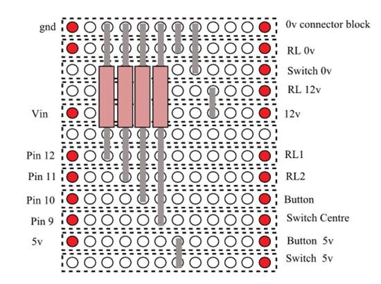
FIGURE 5: The layout of the Veroboard.
FIGURE 4 Building the circuit
Figure 4 shows a schematic for the building of this circuit. As visible on Photo 1 the Arduino has all the pins marked on the board. As we only need a few you can stick a strip of paper label or masking tape on the outside of the pins highlighting the ones we need. On one side we need pins 9, 10, 11 and 12. On the opposite side we need the Vin, gnd and 5v pins.
I glued the Relay Shield on top of the Arduino board with hot glue. Photo 4 shows this. Ensure that none of the soldered connections on the bottom of the shield touch any connections or metal parts of the Arduino. Some UNOs have a large metal guard around the USB connection. Ensure the glue does not foul the USB port as we may need it once the project is built.
We need to build the Veroboard which is very straightforward to construct. Figure 5 is a drawing of the Veroboard, its components and connections. The four resistors and four link wires are fitted and soldered on. The board has a blank face and a copper face – the components sit on the blank face and go through the board to be soldered on the copper side. Ensure you use the correct copper tracks – they should be at right angles to the components as in the picture and that the correct holes are used. Solder carefully to avoid solder crossing to an adjacent copper track.
Five of the connections go to the button and the switch so need five wires. If you choose to use all the same cable in this project ensure the wires are more than long enough to reach from where the Arduino is to be fitted to where the switch and button will be fitted.
Unless you solder them on individually you will need to label them. I used a short length of alarm cable but network cable will do just as well – these multicore cables keep all the wires nice and tidy. Pick five colours to use and cut the others off. There should be either six or eight wires so more than we need. Solder to the button and switch later.
Before I describe the connection a word to those who have bought the shield that plugs directly onto the Uno board. On the veroboard you will not need the wires on RL 0v, RL 12v RL1 and RL2. The direct connections will take their place.
Solder a piece of wire to each of
FIGURE 5

4 5
the remaining Veroboard connections long enough to reach their pins. If you use about 100mm each you can trim later or leave tucked in. Check the soldered side of this board very carefully – I use a magnifying glass. Ensure that there is no solder whatsoever crossing any of the copper tracks. Sometimes there can be very fine stands of solder joining them. They are easy to remove with a Stanley knife.
Glue the completed Veroboard to the top of the relays, again with hot glue or something suitable. Silicone sealant or No-Nails will also work but will take longer to set. Photo 5 is a close up of my finished Veroboard glued to the top of my relays.
We can now finish the wiring. The wires from the left side of the Veroboard go to their pins on the Arduino board. They are gnd, Vin, 5v, 12, 11, 10 and 9. Route the wires as three of them will need to cross the boards. I routed them across the centre between the banks of relays. Trim to length and strip about 8mm from the end. The bare wires just push easily into each pin hole.
From the right side of the Veroboard RL1, RL2, RL 0v and RL 12v go to their relevant connections on the relay board. They are appropriately marked on the board. Looking back to Photo 4 you can see the small black connector block between the relays. The 0v and 12v connections on the Veroboard go the supply from your loco’s batteries. If you do not have a 12v supply on your loco you will need to fit a voltage reducer board from your main supply. DO NOT supply the Arduino with more than the voltage a 12v battery would supply which should be a maximum of 13v.
Do not connect the horns or their supply to the relays yet. Connect your previously soldered wires to the rear of the button and the switch once they are fitted to your loco control panel. The two button wires are soldered each to a terminal on the rear of the button. Switch centre is soldered to the centre connection of the switch. The other switch wires go to the terminals each side of this connection. Solder the switch 5v wire to the terminal that will correspond to the long blast position on the switch. This will be the terminal opposite the throw of the switch.
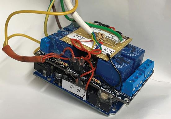
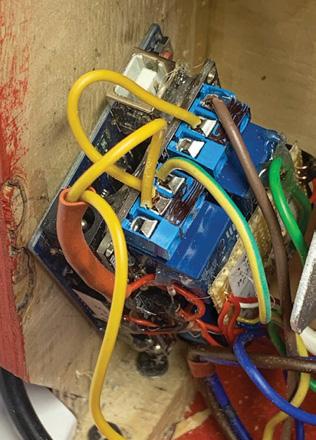
Photos 6 and 7 show the finished assembly complete with all cables and boards. You will notice on these photos that I have stuck labels on various bits to make sure I don’t mix up the connections.

6

PHOTO 4: Relay shield glued onto the Arduino Uno.
PHOTO 5: Completed Veroboard glued on to the top of the relays.
PHOTO 6: The completed board assembly.
PHOTO 7: Top view of the finished assembly.
7
Testing the electrics
Turn on your 12v supply to the Arduino – it will need a few seconds
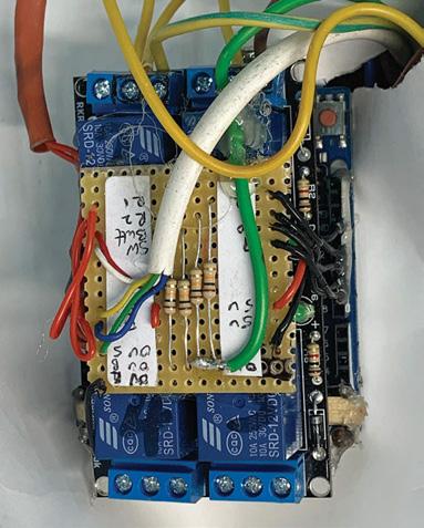
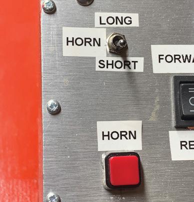
to boot up. Once booted you should be able to see the onboard LED glowing. Photo 8 shows part of my control panel detailing the horn switch and push button.
Move the switch to the short-blast position and press the button. You should hear the two relays click on and off one after the other. If they work move the switch to the long-blast position and press the button again. You should hear both the relays click on and off again but with longer intervals between the clicks.
If it works in both positions the programming and wiring are all correct. If not switch off and check all your connections are correct and secure. If it then does not work plug in to a computer, check the programming is correct in the IDE and upload again to the Arduino.
Assuming all tests okay you can wire the horns. The larger terminals at the end of the relays are used for this. The com terminal is for your horn supply to suit the horns you are using. We used cheap twin car horns so needed a 10a 12v supply. If you have had to fit a voltage regulator to supply this project ensure it is capable of more than 10 amps. If you have a 24v main supply you can use this for the horns if you buy 24v lorry or bus horns.
The n/o connector from the relay goes to the horns – relay one to horn one and relay two to horn two. Both the horns can have their 0v terminals connected together and wired to your 0v or negative on the loco. It is worth wiring your 12v supply to the Arduino through an isolation switch on your control panel just in case.
Before fitting to your loco run some glue or silicone across the wires in the Arduino pins to avoid them being accidentally pulled out or vibrating loose.
Operation
When you switch your power on you should again wait a few seconds for the Arduino to boot up. With the blast switch in the short position press the horn button. You should get a short blast of the horns. Switch the switch and you should get the alternate long blast when the button is pressed. If the blast times don’t match the switch position either loosen the switch and rotate it through 90 degrees or swap your labels over.
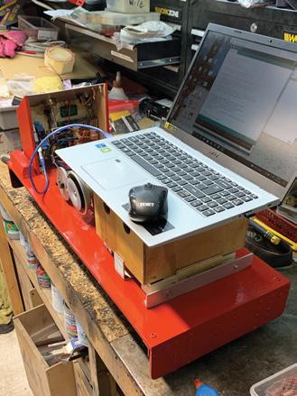
If you want to change the duration of the blasts change the delay times in the sketch and after plugging the computer in to the Arduino upload it. As you can see from Photo 9 a laptop is ideal for reprogramming this system once fitted to your loco. The new altered sketch will replace the previously uploaded one. You can do this as many times as you need to get the particular blasts that you want.
The Arduino/relay/Veroboard assembly can be fitted in your chosen place on your loco with hot glue, silicone, No-Nails, sticky pads or any other method you choose. Just ensure no connections can touch any metal that can short them together. Photo 10 shows my assembly glued inside my control box. Note that the USB can easily be accessed for reprogramming.
This controller is fairly straightforward to build and if you choose can be altered to suit your requirements. By carefully adding more digitalWrite and delay commands you can make the blasts double or treble sounds. If you wish you could add more horns to change the sound of the blasts. This will need more relays but if, like me, you bought the four-relay board you already have two spares. If you read and understand the programming you should be able to add the extra horns to the sketch. Do one at a time and test after each addition. You will need to name the extras and set some more output pins to write to. The knowledge to do this is in this article.
I encourage you to have a go but keep a copy of your original working sketch so you can load it back in if you need to. Save your new Sketch with a different name. If you choose to do this put a comment on every line so you can keep track of what you have done. At the beginning of my sketch there is a description of the sketch. Rather than using // on every line for this you can start and end it with /*. Everything between these two markers will be ignored by the Arduino.
Wide-ranging uses
I hope I have shown you enough to venture into the interesting and useful world of Arduino processors. They may be useful for other projects you may attempt and can solve some important problems if used. Programming knowledge can be expanded as you need it and there are plenty of forums and people online who will usually help out. There are also many thousands of sketches posted on the internet for free. If they don’t exactly fit your requirements you can always alter them. There are many examples on the IDE program already. They are in the File dropdown menu under ‘Examples’.
I hope my Sketch can be hosted by EIM for downloading to save you all the typing and faults but I encourage you to type your own while following this article. I also suggest you alter or add to it to further your knowledge of these very useful boards.
9 8
PHOTO 8: The horn blast switch and push button fitted on the loco control panel.
PHOTO 9: Updating the Arduino with a laptop after fitting to the locomotive.
PHOTO 10: Installed and working in the loco control box.
EIM
n Readers who would like a copy of Julian’s sketch file can request one by sending an email to editor@ engineeringinminiature.co.uk

