19 minute read
1. TENSEGRITY STRUCTURES
1. TENSEGRITY STRUCTURES
The Tensegrity concept offers a high level of geometrical and structural efficiency when the external load acting on construction is transmitted to all elements of the structure in the same way. Once the external force is removed the elements will return to their original shape. Vibration in one part of the structure causes vibration in all other parts (Motro, 2003). The mechanical stability of structures does not depend on the strength of individual parts but the whole structure distributing and balancing mechanical strain. Tensegrity is a relatively new design principle that applies when a discontinuous set of compression elements is opposed and balanced by a continuous tensile force, thereby creating an internal prestress that stabilizes the entire structure. Tensegrity structures are a particular class of lightweight structural systems. Tensegrity is based on the use of isolated components in compression inside a net of continuous tension, in such a way that the compressed members (usually bars or struts) do not touch each other, and the prestressed tensioned members (usually cables or tendons) delineate the system spatially. Tensegrity systems were introduced in structures approximately in the middle of the 20th century within the work of Fuller and Snelson. They can also be defined as a set of compressed bars inside a continuum of tense cables, the whole being in a stable self-stressed state. The tensegrity system can effectively use compression and tensile elements, which allow significantly reducing the weight of the structure. The word tensegrity was coined by Richard Buckminster Fuller in the 1960s, by combining the words tension and integrity (R.B.Fuller, 1962, and K. Snelson, 1965). The first patented definitions of tensegrity are very general. Fuller described tensegrity systems as “Islands of Compression in a Sea of Tension”. Snelson patented the system which he called “Continuous Tension, Discontinuous Compression Structures”. Richard Buckminster Fuller (1895 - 1983) was an American engineer, architect, inventor, and futurist. He developed the famous Geodesic dome – a spherical form in which lightweight triangular or polygonal facets consisting of either skeletal struts or flat planes, largely in tension, replace the arch principle and distribute stresses within the structure itself. Kenneth Duane Snelson (1927 – 2016) was an American sculptor and photographer. He was one of the first to build tensegrity sculptures and he defined tensegrity as a closed structural system composed of compression struts within a network of tension tendons. He liked to describe his tensegrity sculptures as floating compression. Snelson considered tensegrity as a connection between architecture and art.
Advertisement
Kenneth Snelson, after completing lectures and Fuller's practice at Black Mountain College in North Carolina, created a catalytic contribution to understanding the construction of tensegrity when he collected his X-Piece statue.
I think that part of the reason that the beauty and construction of tensegrity did not come into practice, even in circles where there was a strong interest in the practical application of tensegrity, is the clear lack of professional and intelligent workers as well as the precise tools for realizing their design and creation. Fuller's basic model of tensegrity patent has quotes of element length, but no indication of how lengths would be proposed. Probably the lengths were then calculated and parameterized, as measured by the length of the elements of the finished structure The main shortcomings and problems of the practical application of tensegrity technology for the practice these artists have identified are: 1. Low Load Response - "Relatively high deformation and low material efficiency compared to conventional, geometrically rigid structures." 2. The complexity of the production of details - spherical and domical structures are complicated to produce details of joints as well as the selection of suitable material for their realization, these factories can lead to production difficulties. In other words, in a tensegrity structure the two types of forces in nature, tension, and compression are completely separated and you can see them in their pure state. Where there is a strut, there is pure compression; and where there is a cable, there is pure tension. Then we can describe the characteristics of a tensegrity structure as follows: The structure is free-standing, without any support. The structural members are straight. There are only two different types of structural members: struts carrying compression and cables carrying tension. The struts do not contact each other at their ends.
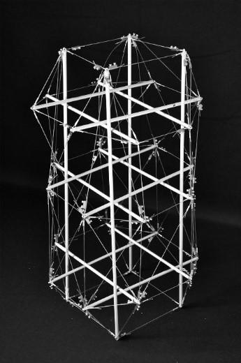
The response to the loads is nonlinear. French architect and engineer David George Emmerich (1925 – 1996) added the condition of a selfstress state: Tensegrity structures consist of rods mounted in such a way that the struts remain physically isolated in a continuous set of cables (D.G. Emmerich, 1964). However, according to some sources, structures based on the principle of tensegrity were explored and identified as early as in the 1920s by the obscure Latvian artist Karl Ioganson whose physical models were destroyed by the Soviet regime (D.G. Emmerich, 1964). Fig. 1.1a, b shows physical models of two tensegrity structures: a high-rise building of rectangular shape Figure 1.1a and a shell geodesic dome based on the idea of Fuller Fig. 1.1b. “Geodesic” means the shortest distance between two points. The geodesic structure consists of as many struts of the same length as possible as well as congruent surfaces. It is a network of equal triangles whereby the cross points are always situated on the surface.
This triangulation guarantees the strength and rigidity of the ball-shaped structure. There is no direct contact between the compression elements as seen in Fig. 1.1a, b. The struts are combined into triangles, pentagons, or hexagons, whereby each strut is aligned in a way that each connection point is held in a firm position. This guarantees the stability of the whole structure. Tension is distributed equally to all parts of the whole construction. Increased tension in one part provides increased tension in all parts. A global increase in tension is balanced by an increase in tension in various parts. Whilst tension is thus distributed evenly in the whole system, only individual parts are balanced by compression. There is a balance between tension and compression, we can define the system as “stable self-equilibrium”. It is a self-stabilizing whole system. The tensegrity network is a stable, at the same time adaptable construction. The whole system reacts to an outside force with an adaptive tension distribution. Both types of structures depicted in Fig. 1.1a, b use separate elements for tension and compression as we can nicely see in this visual example. The tensegrity systems can be defined as spatial structures consisting of compression (struts) and tensile (cables) components that stabilize each other through pre-stress, tension, and compression work together to resist the applied load. In our models, struts are made of aluminum or wood and nylon or steel fibers represent cables or tendons.
1.1a 1.1b
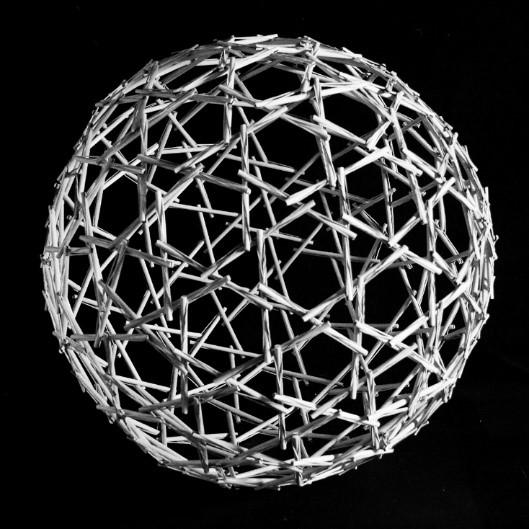
Fig. 1.1a, b. Tensegrity Tower and Geodesic Tensegrity Dome (models created by the author)
There are several problems associated with tensegrity systems, and the primary one is the geometry of the structure. The self-stressed equilibrium of the structure is determined by the form-finding method. Since much of the ideas on tensegrity structures have been developed based on existing identification with nonlinear geometrical behavior, it also follows that the challenges identified are also on the same track. Firstly, analytical form-finding methods need to be developed. 8
Without the proper analytical form findings methods, it would be impossible to understand high order tensegrity structures. Secondly, form-finding for arbitrary tensegrity structures is seen to involve only a little knowledge of structure. This is especially the case with structures such as spheres, cylinders, and others. There are challenges in simultaneous form-finding, also there are constraints in understanding the member length and axial stiffness parameters. Sometimes, the advancement in the context of parameter identification poses a challenge as well. In form-finding of assemblies, there are difficulties in identifying the known tensegrity units and the unknown tensegrity grids. Contrary to developing and optimizing structures using intuition and experimentation, form-finding is the determination of the design of the tensegrity geometrical configuration analytically. The configuration found should also keep the tensegrity structure in a state of equilibrium. Form finding studies have been carried out on tensegrity structures from the early research studies of Fuller and Snelson. The tensegrity structures that they formed were mostly convex polyhedron based. They used this geometric research to understand the existing structure and understand how to formulate newer configurations if possible.
Tensegrity structures can be seen as “internally pre-stressed, free-standing pin-jointed networks, in which the cables or tendons are tensioned against a system of bars or struts.” This description introduces the fact that the system is pre-stressed and pin jointed. This implies that there are only axial forces present in the system and there is no bending or torsion. The tensegrity concept offers a high level of geometrical and structural efficiency and results in modular and lightweight structures. When the external load acting on construction is passed on from one element or place to another element of the structure finds a new form. Once the external force is removed the elements will return
to their original shape. Vibration in one part of the structure affects vibration in all other parts.
Fig. 1.2 shows the author´s physical models of the series called “Tensegrity Land” which were presented at an exhibition in Prague, in 2019. These tensegrity structures serve as table lamps.
One of the most elegant tensegrity forms is a three-struts T-prism Fig. 1.3: nine tendons, three struts single layer, twist element that rise to the open space. A triangular tensegrity prism was probably first made either by a Lithuanian artist K. Ioganson around 1920 or by a student of R. B. Fuller at the University of North Carolina in the early 1950s named Ted Pope (Snelson, 1965, and Emmerich, 1964).
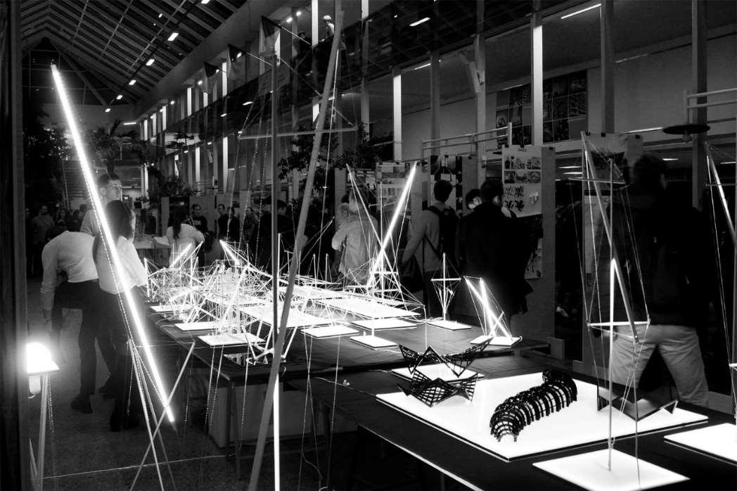
Fig. 1.2. Tensegrity Land (models created by the author)
The tension of the cable is applied to each strut (compression) element. As it is a threedimensional system, at each end of the strut we should have at least three cables in tension attached to the node to ensure the stability of the entire structure. Based on this principle, we created a triangular tensegrity prism that can serve as a nice hammock for public space which is depicted in Fig. 1.3.
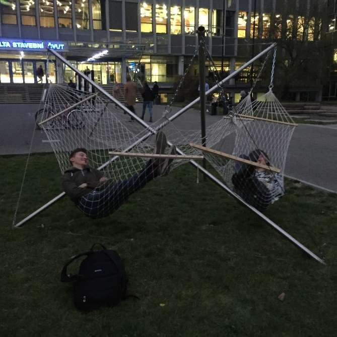

Fig. 1.3. Orthogonal Triangular Tensegrity Prism (Shawkat 2019)
All members of a Tensegrity structure are axially loaded. Generally, members that experience deformation in two or three dimensions are much harder to model than members that experience deformation in only one dimension. Hence, increased use of tensile members is expected to yield more efficient structures. let me now present some small scaling models for illustration, to give the idea of tensegrity to the readers in a simple way.
Orthogonal Tensegrity Prism: It is the most elegant tensegrity one can conceive, three struts Tprism, nine tendons, twist an element, 3 struts single layer, rise to the open space, this 3‐strut T prism was probably first made either by a Lithuanian artist Karl Ioganson around 1920 or by a Fuller student at the University of North Carolina in the early 1950s named Ted Pope. But both Karl's and Ted's contributions helped the development of the tensegrity stops here. We are not even sure they indeed build this principal tensegrity. Each strut is acted upon by the tension of the cable. As it is a threedimensional system, at each end of the strut we should have at least three cables in tension attached to the node. This is also observed by Snelson: “I know I need a minimum of three cables on any end of any stick” (Snelson and Von Baeyer, 1989). The resultant of each triad of forces at each node, added to the relatively small weight of each component, must be in line with the axis of the strut because otherwise the rod would be affected by a bending moment and would not be in equilibrium, i.e. there is a three-dimensional equilibrium of tensions and compressions at each node. From this analysis, we can understand that the definition of tensegrity structures as internally pre-stressed, freestanding pin-jointed networks, in which the cables or tendons are tensioned against a system of bars or struts”.
To make a parametric design for Tensile integrity structure, we create algorithmic editors that ordinarily consolidate visual programming dialects using Grasshopper inside Rhino Fig. 1.4 and Fig. 1.5, to overcome the imperatives of the interface, and to design specifically, overseeing not the form, but the code that produces the shape. Parametric, in mathematics, is a set of quantities expressed as an explicit function of several parameters, according to the set of results determined from the parameters (string length, anchor point location, birdshot weight). Kangaroo refined in terms of goals and kind of other things, so the idea is like there are different features that you want to adhere for example to behave as a hinge or to behave as a minimal like surface as a soap film. It’s going to try to create a form that is based on that but what it is not looking at is like, what the object is made from you know it’s not considering cross-section or materiality, and specific things like bracing or like pins as well as verses hinges. If you are looking at form and you know kind of computation this is a very quick way of resolving some things and kind of making some progress and they are based on the structural principles which I think are interesting.
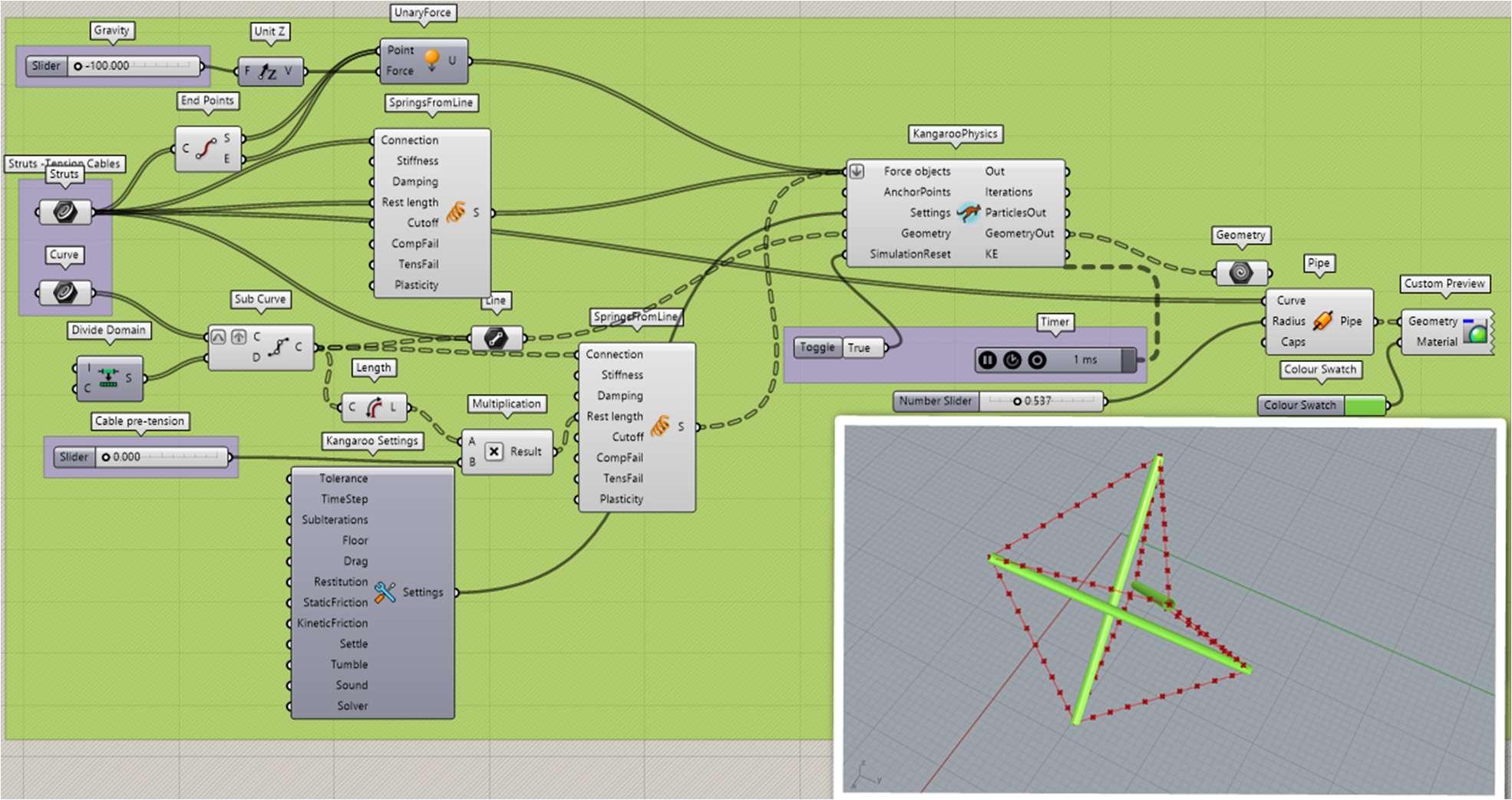
Fig. 1.4. Process of Thinking in the Grasshopper Programme
Fig. 1.5. Process of Thinking in the Grasshopper Programme
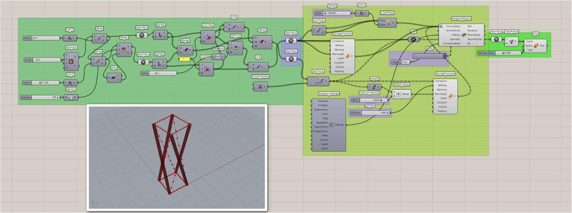
The same reasoning could be applied to the wires, which are attached to the ends of two struts and influenced by, at least, the other two cables in each node. As a result, each join is in equilibrium if it is put under a particular tension, which is usually a pre-tensioning force. As you can see in Fig. 1.6a, this construction is made of one tensegrity spatial 3D element consisting of six X-shaped modules (six strut elements of equal length and shape). The strut elements are oriented in three mutually perpendicular axes, each having the same length, and eighteen cable elements. Three cables pass through each node. The assembly of triple-X shapes provides structural morphology of tensegrity systems and adding tension cables to the components gives a stable state to the structure, therefore, preventing a motion of the triple X-shapes out of their plane.
The process is started with a simple system and next, more and more struts and cables are added step by step, however, the strut elements must not touch together. The upper edge of the struts must be connected to the lower edge of the other elements. The properties such as weight, the thickness of the elements, and the use of the same material in all directions have an influence on the stability, and equilibrium of the structure (Snelson,1965, and Motro,2003).
Fig. 1.6a presents our physical models of triple-X shape tensegrity showing their structural beauty. We have transformed them into interior components, namely table lamps to show some of the other possible functions of this creative tensegrity design.
The weight, thickness of the elements, and the use of the same material in all directions influence the stability of the structure.
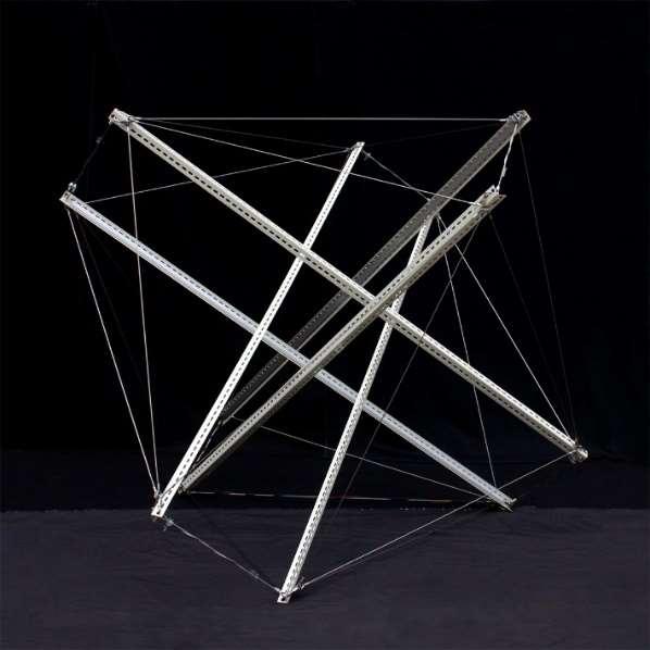
Fig. 1.6a. Tensegrity Icosahedron (model created by the author)
The tensegrity as a pin-jointed network they are more flexible under light loads, but their stiffness increases rapidly as the load is higher, like a suspension bridge (Kenner, 1976; Smaili, 2003; Wang 2003). In the absence of externally applied loads, tensegrity, as a type of form-active structure, needs selfequilibrium configuration as determined in the process called form-finding.


Fig. 1.6b. Expanded octahedron” or “Icosahedron” Physical model Tensegrity Icosahedron (Shawkat)
Fig. 1.6c. Process of Thinking in the Grasshopper Programme
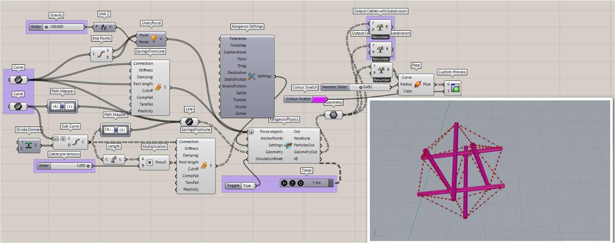
The form-finding state determines the self-equilibrated configuration in the absence of externally applied loads, but they are not always defining other characteristic features of tensegrity structures. Tensional forces naturally transmit themselves over the shortest distance between two points, so the members of a tensegrity structure are precisely positioned to best withstand stress. For example, if the configuration of an “expanded octahedron” is changed and the cables are fixed following the zigzag pattern Fig. 1.7 the result is a “truncated tetrahedron”. As Motro (2003) remarked, it is not always possible to attain a balanced geometry and, therefore, sometimes the figures do not have a perfect definition of the polyhedron in question. Due to the orientation of the struts that converge in each face, it can be appreciated that a certain distortion of the regular polygons can arise. 14
The potential of the tensegrity concept has inspired new metamaterials. Metamaterials are artificially invented materials that have properties that are not observed in nature. These are composite structures with extremely unusual mechanical properties. In recent years increased interest in the research of metamaterials has been observed.
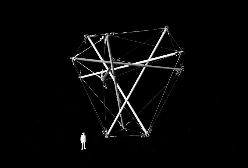
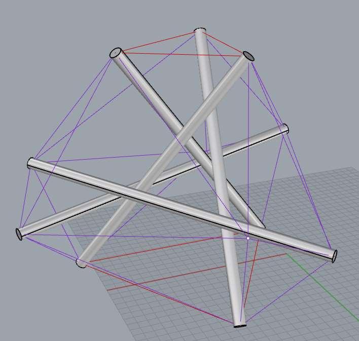
Fig. 1.7. Physical model Diamond T- Tetrahedron (model created by the author)
We also proposed one interesting model, Fig. 1.8 this is a geodesic tensegrity dome inspired by the author, where the tendons could be substituted by a plastic skin that took the role of the continuous tension component. The adjacent figure shows the model is a dome fragment that can be used as the roofing of different spaces: representative, indoor, and exhibition. It is constructed from aluminium tubes (struts) and nylon fiber (rods). The struts do not touch each other. The model consists of 15 basic modules that are mutually connectable and detachable. The base module has three struts’ bars with a diameter of 6mm and a length of 166mm. The upper base rods are 140 mm long, the bottom base rods are 80 mm long. The rods connecting the lower and upper bases are 115 mm long. The top base of the base module is 1.75 times larger than the bottom base, ensuring a dome-shaped curvature when bonded. In practice, it would be appropriate to use a smaller ratio for a larger dome span. The basic modules and the whole structure are removable thanks to the rods. The joint is a cut slit into the aluminium tube into which the rods are inserted. The rods are terminated at the end with a node that is larger than the slot to avoid the collapse of the structure. In practice, it is advisable to use solid joints.
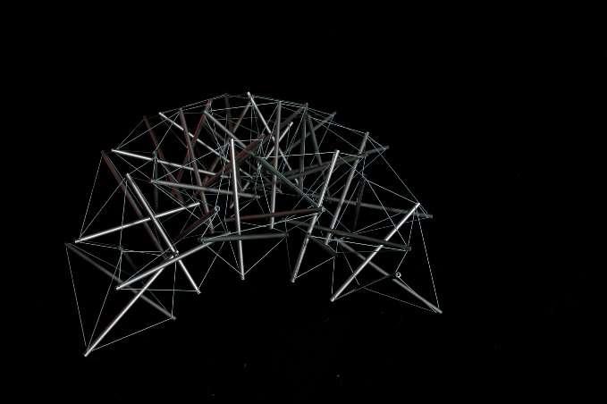
Fig. 1.8. Physical model - Double-Layer Tensegrity Dome
Fig. 1.9. Physical models – Tensegrity (models created by the author)
Fig. 1.10. Table Lamp (Model created by the author)
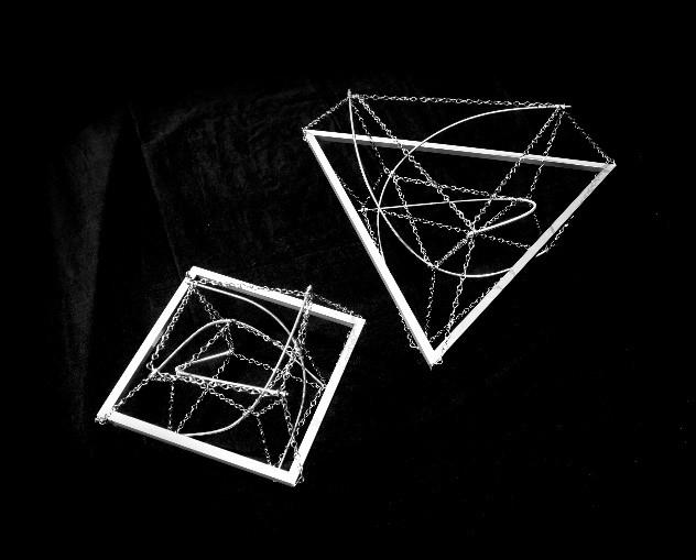

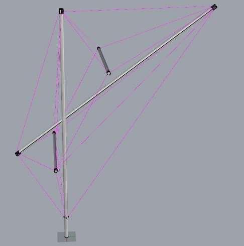
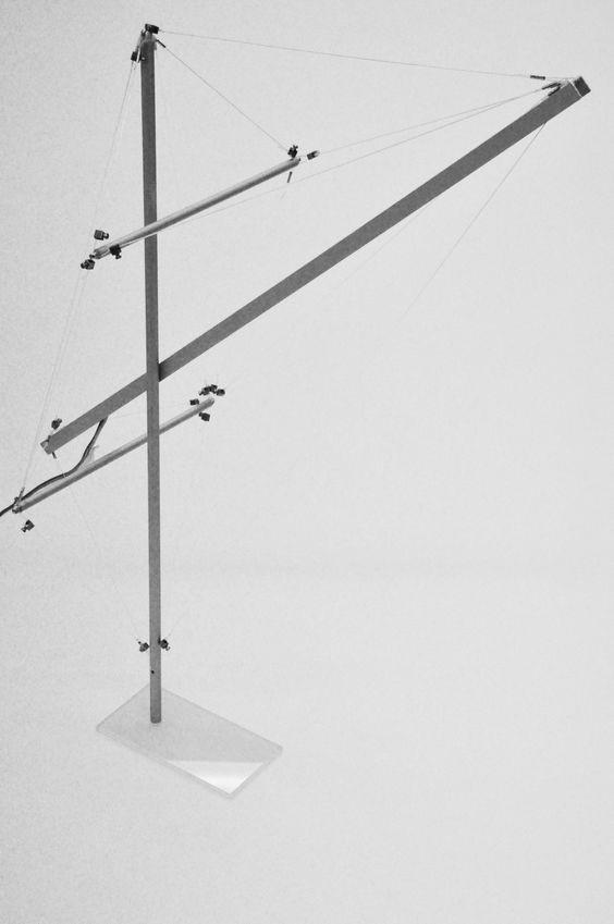
All tensegrities are prestressed under tension; they are self–supporting and independent of gravity. But the weight of the structure also adds to the prestress. All components are dynamically linked such that forces are translated instantly everywhere; a change in one part is reflected throughout the whole structure.
The stability of prismatic tensegrity structures is not only determined by the connectivity manner of the members but also sensitive to the height/radius ratio and the stiffness/prestress ratio. Our team of structural designers started to deal with this kind of fine art of structure in the year 2008. Together with the students, we try to bring fresh ideas into the field and create different models of tensegrities. In this chapter could be found various models used for living and pleasure as furniture, table lamps, and toys. We pay attention not only to the structure itself, but also to details, aesthetics, and the elegance of the models. Each node of the structure is connected by two horizontal cables within its horizontal plane and is connected by one vertical cable and one strut to nodes in the other plane. The thick and thin lines denote, respectively, cables that can only carry tension, and struts that carry compression. These structures are called super stable.
In the model structures shown in this chapter, the tensile members are usually cables or rods, while the compression members are sections of tubing. The tensile members can be thought of as cables that pull two points together, while the compression members can be thought of as sections of rigid tubing that maintain the separation of two points. The tensile members are continuously connected to the ends of the compression members while the compression members are only connected to tensile members and not to other compression members. The results of our design process are presented also graphically. To determine the equilibrium position the lengths of the struts are specified, which are assumed to be all the same, together with the stiffness of the top ties (assumed equal), bottom ties (assumed equal), and connecting ties (assumed equal). One of our physical tensegrity models is an amazing chair shown in Fig. 1.11 We can use it to clarify the main ideas of tensegrity and demonstrate the entire concept for educational purposes and at the same time, it serves as an unusual chair. Our experience and way of thinking are conditioning the quality of our proposal. Similarly, training conditions are also very important, and common training with other professions may contribute to increasing the level of our art of engineering.
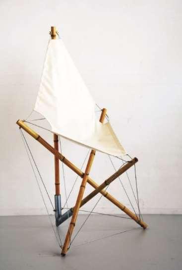
Fig. 1.11. Tensegrity as a Chair (Shawkat, and co-authors 2019)
Fig. 1.12. Tensegrity art -Design systems- Parametric Modelling (models created by the author)
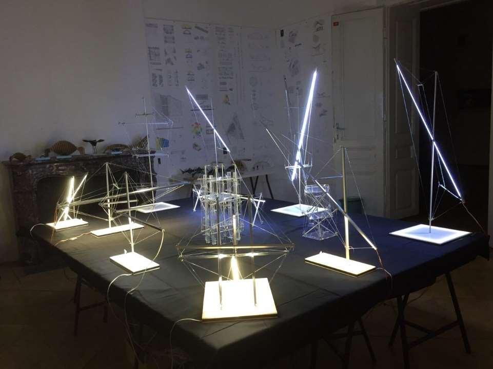
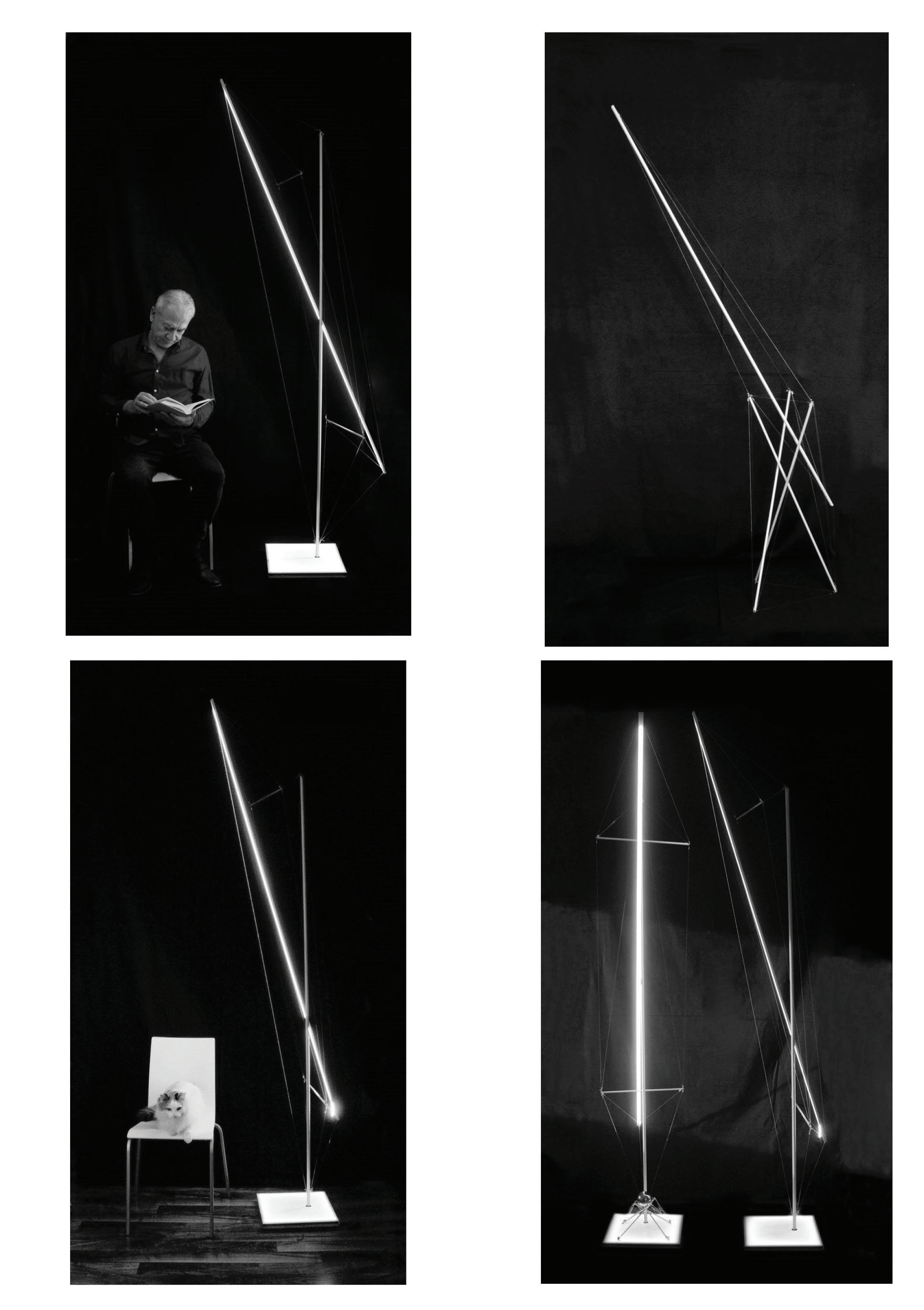
Fig. 1.13. Tensegrity art - Parametric Modelling (models created by the author)
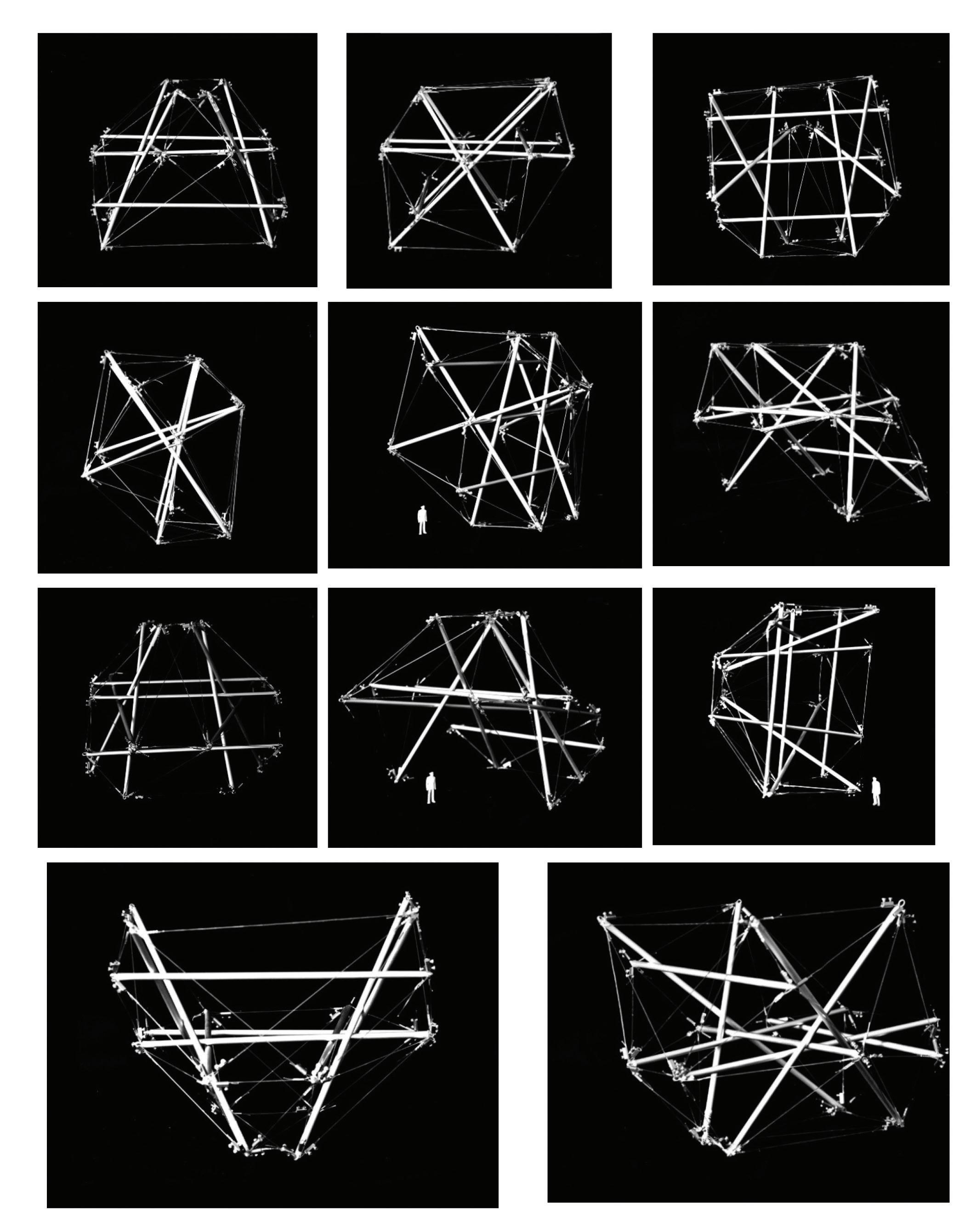
Fig. 1.14 Parametric Tensegrity Form Finding-Physical models (models created by the author)
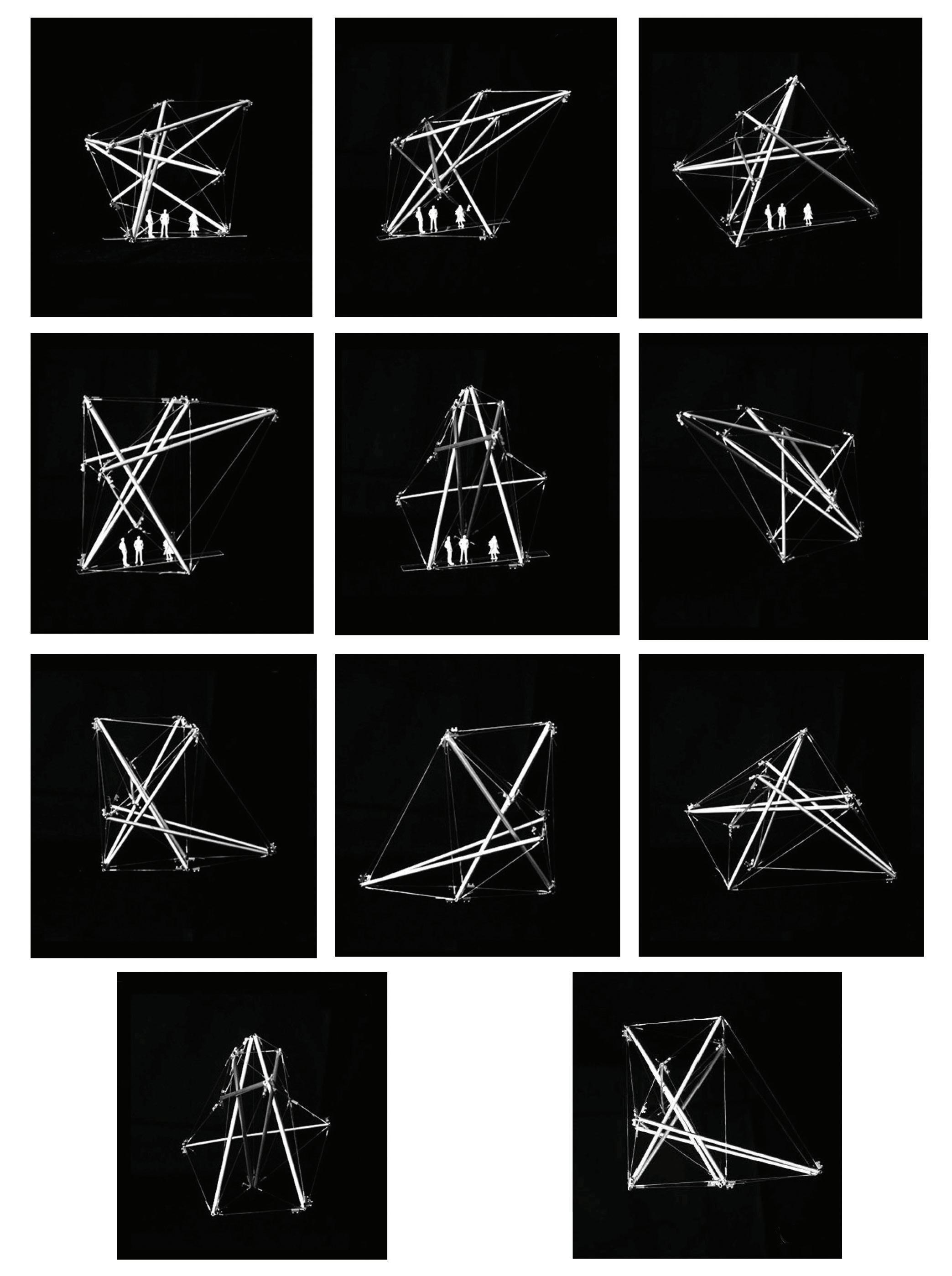
Fig. 1.15 Parametric Tensegrity Form Finding-Physical models (models created by the author)


