4 minute read
COUPLINGS


President Ruland Manufacturing Co., Inc.
How to avoid coupling failures?
Mechanical couplings have a principal use in the connection of rotating shafts for the transfer of rotary motion and torque. As with all mechanical devices, a coupling must match its intended purpose and application parameters including various performance, environmental, use, and service factors.
When selected with these design parameters in mind — and when installed and maintained correctly — a coupling should have no failure issues over its lifetime. However, if these design parameters are not adequately met, a coupling can fail prematurely. The result might be negligible and a small inconvenience; or it might be far more significant and include financial loss or personal injury so due diligence is critical.
Here are a few of the primary reasons why couplings perform poorly or unsuccessfully, along with the steps that can be taken to minimize failure risk.
Coupling errors Ideally, a coupling must fit its intended application, meeting the required performance factors. However, a design engineer must also consider additional criteria and address issues relating to the application environment (for example, heat, cold, vibration, humidity, debris, etc.), serviceability, and potential maintenance requirements.
One key is to think ahead. The availability of a new coupling for future replacement if or when necessary should be planned for in advance. Preparation is critical as downtime can seriously affect many processes, leading to lost uptime and revenue.
A common mistake in design selection is an incomplete understanding of what the manufacturers’ product specifications mean. For instance, when the manufacturer provides torque data, carefully review how it’s stated and if there are other service factors to consider. Jawtype couplings are typically expressed with an operating and peak torque to account for use in start/stop applications. But this differs from beam couplings, which are usually expressed using static torque and derated based on use.
A designer must fully understand these specifications and the design criteria for the system or application under review to select the ideal coupling. Another common mistake is mismatching the coupling to the equipment’s misalignment condition. The goal of shaft alignment is to increase the reliability of rotating machinery. However, misalignment is not uncommon.
For example, with parallel misalignment, the center lines of both shafts are parallel, but they are offset. Angular misalignment is the opposite,
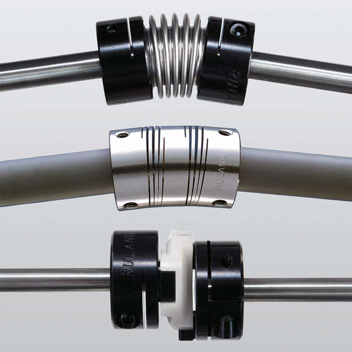
At work and working properly: three types of Ruland couplings on shafts (from top to bottom): bellows, beam, and Oldham couplings.
where the shafts are not in the same horizontal or vertical planes.
These are important distinctions, and the proper selection of a coupling cannot be made correctly without an overview of the application and an understanding of the misalignment issue being addressed in the system. The goal of ensuring alignment is to increase the reliability of rotating machinery.
Consequences A mismatched coupling for a given application can have several consequences. When one or more of the design criteria and overall system attributes are not met, a coupling is likely to fail. Coupling failure can lead to equipment downtime, unplanned maintenance, financial loss, or more serious human injury.
Mechanical couplings are typically used for connecting rotating equipment shafts for the transfer of motion and
torque. A coupling choice that does not accurately account for the torque requirements, including the starting and stopping torque as in servo-motor applications, can result in failure and potentially harmful consequences.
When shaft misalignment is a design factor, a beam coupling is usually a good performance and economic choice. Beam couplings are ideal for handling angular misalignment and axial motion. However, failure may occur in applications with parallel misalignment. This is because the single beam must bend in two different directions simultaneously, creating larger stresses in the coupling.
When excessive parallel misalignment exists in the application other types of couplings should be considered, such as bellows and Oldham, subject to the system design criteria.
Choosing wisely Choosing a coupling for an application can be a complex process but should not be overly time-consuming. The best advice is to carefully consider all of the system design criteria.
Typically, these include: torque, shaft misalignment, stiffness, rpm, inertia, space requirements, shaft mounting, and there are others.
Selecting the ideal coupling is not the end of the job. It’s equally important to install it properly, verifying that the design considerations were followed and correct for the application. For example, there might be a greater or lesser degree of misalignment than originally specified.
Additionally, ensure that the application assembly is regularly maintained so that the design parameters are up to par. It’s important that no system component or coupling wear, contamination, or other detrimental factors have been introduced into the assembly.
How to maximize production and minimize coupling failures? When specifying and installing a coupling, ask these questions…
• What are the accuracy requirements? • Does the application require high torsional stiffness? • Is dampening or shock absorption necessary? What about electrical isolation? • How much misalignment is present in the design? Is it angular, parallel, axial, and/or complex? • Does the coupling need to be fail-safe? • What speed and temperature will the coupling be operating at? • What is the maximum torque that will be applied to the coupling? • Are there other environmental factors to consider for the application?
Far too often motion control couplings are selected exceedingly late in the application design process. Yet, these components are critical to successful system performance. Early selection will reduce errors along with the potential for premature coupling failure.
The keys to avoiding coupling failure are correct coupling selection based on the design parameters, proper installation, and periodic system maintenance.
To learn more, go to tinyurl.com/ MechanicalCouplings
A beam coupling has failed near the center, representing what can occur in a torqueoverload condition.


