10 minute read
Motion control goes small


Machine designers are increasingly asked to build systems that take up less space, operate on less power, and run with higher performance. Thankfully motion controls are answering the call with new motors, new sensors, and new architectures.


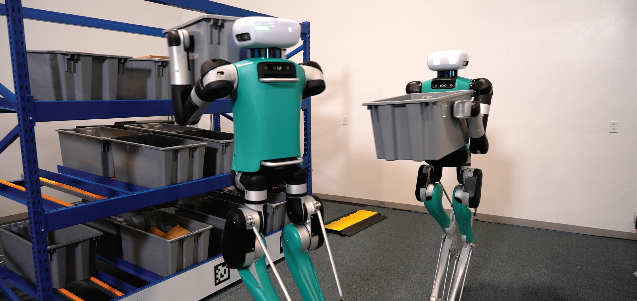
It seems that every day there are announcements of smaller and smaller motors, controls, and sensors used in precision motion control. What is driving these applications is the growing demand for motion control components used in surgical, patient treatment, mobile robotics, drones, and battery-powered applications. In this article we will introduce you to recent developments in motion control technology that are letting engineers build systems that use less power, make less noise, and take up less space.


We will look first at the motors themselves to understand how they are evolving and assimilating new sensor and control techniques to boost their performance. Then we will focus on controls to show not just how and why motion control components are physically shrinking, but how new control techniques are being used to maximize motor and system performance.
Finally we will look at how the evolution of motors and controls are impacting architecture. Because it turns out that smaller and more e cient controls allow entirely new approaches to where the controls are located, how they are wired, and how these changes are having a major impact on performance, reliability, and cost.
Mini motors 101
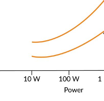
When comparing various motor types, power output to weight and torque output to weight are two key performance metrics to consider. For a given application, usually one of these two factors are more important than the other, and in fact, they are related because power is defined as torque times spin rate.
Brushless DC motors, with their ability to generate a constant torque up to a high spin rate, typically provide the highest figures of merit for power output to weight. Typical values are double the ratio of DC Brush motors. Step motors, although equently used in portable applications, are not usually part of the power to weight conversation because their torque drops off rapidly as rotation speed increases.

If we instead want to optimize torque to weight, step motors are back on the table. Traditionally open-loop operated step motors have high holding torques, but their ability to deliver that torque over a working speed range is affected by their tendency to oscillate. Practically speaking, this means the effective torque delivered by the step motor is between 50% and 70% of the motor's rated holding torque.
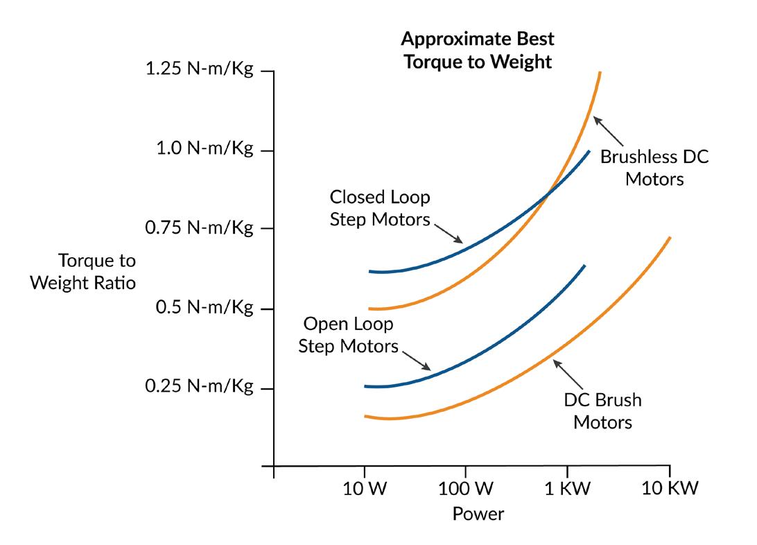
There is an alternate way of operating a step motor however which largely solves this issue. A technique called closed loop servo, also called stepper servo, uses an encoder to operate the step motor as if it were a two-phase Brushless DC motor. The result is significantly higher torque over the operating range of the motor because mid-range instability, a torque killer for open loop step motors, is eliminated. More on this up and coming technique a bit later in the article.
I sense a change
An interesting aspect of the evolution of motor/actuators is how they utilize (or not utilize) sensors. As motors get smaller and smaller, and as they are implanted or strapped on to patients or used in mobile robots, it becomes harder and harder to add sensors without impacting the motor package size or the robustness of the motor/sensor combination.
So one trend affecting motors is sensorless operation - eliminating sensors and operating the motor using control techniques such as back-EMF (for Brushless DC motors) or electronic stall detection (for step motors).
There are simple and fancy ways to utilize the back-EMF of each winding of a Brushless DC motor. The most straightforward is to measure the backEMF of a floating leg while the other two legs are being driven. The floating leg, no longer influenced by the drive output of the amplifier, contains the back-EMF voltage which can be used to determine the zero-crossing point, allowing a specific location of the commutation cycle to be determined.
Back-EMF works very well under the right circumstances but has so far not been adopted in general purpose motion applications. The first challenge is that back-EMF signals disappear as the velocity of the motor decreases. So, for all practical purposes sensorless Brushless DC applications cannot be used in positioning applications where the motor needs to be controlled around a stationary location.
In a velocity control application, however, sensorless drive has seen significant adoption. Although we still have the problem of not being able to sense back-EMF signals at low velocity, the controller can overcome this limitation by using a microstepping drive technique (operating the Brushless DC motor as a step motor) to bring it up to speed and then switching to back-EMF commutation once the measured backEMF signal provides su cient signal to noise.
When it comes to step motors, sensorless operation means more or less the opposite. Step motors can position all the way down to zero velocity but need help as the velocity increases, where they are prone to losing steps or having the motion collapse altogether. Sensorless electronic techniques can help by reducing the tendency to oscillate at certain speeds and by detecting that the rotor has stalled.
However the same "it works till it doesn't" limitation that applied for sensorless Brushless DC motors operation applies here as well. It is di cult to guarantee that electronic stall detection will work 100% reliably, so step motor applications that are really mission critical tend to use an encoder to confirm the motion.
When the going gets tough the tough get sensing
Strangely, motors of all types including very small motors are also trending in the opposite direction, upgrading their sensors to overcome the robustness limitations mentioned earlier, or adding sensors to motor types that previously did not use them.
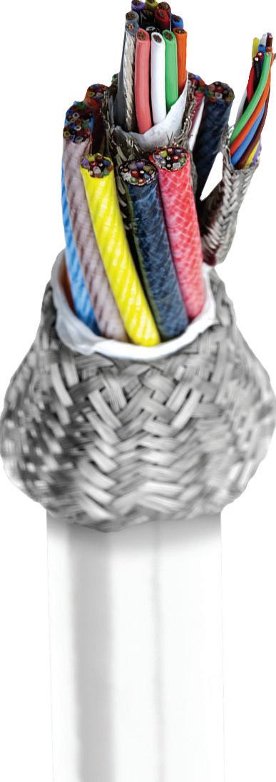
Upgrading the sensor for robustness o en means moving away om optical sensors, which are otherwise the workhorse of motor position sensing in the form of the quadrature incremental encoders. So to address the needs of harsh environments and medical applications there has been an uptick in the use of non-optical sensing solutions such as magnetic and capacitive encoders.
Magnetic encoders can be hermetically isolated om the motor, measuring the position through a small air gap. The motor's rotor carries a magnetic encoding disk typically mounted at the very end of the motor sha , while the electronic portion of the encoder uses either Hall sensors or magneto resistive sensing techniques to determine the rotor position. Magnetic encoders have leapt forward in resolution since their inception, and now can provide quadrature resolutions of 1,024 counts per rotation or more.
Capacitive encoders can also be hermetically sealed om the motor, and therefore have seen growing interest for use in harsh environments and medical applications.
Aiding the adoption of these new encoder types are improvements in the controls which use high precision A/ Ds (Analog to Digital converters) and algorithmic techniques to compensate for small irregularities in the encoder's analog output signals along with fast arc-tan calculations to generate resolution-enhanced position values.
Funny, you don't act like a step motor Step motors aren't normally operated with an encoder, but are now going through an evolution which relies on an encoder to operate the motor as a servo motor- essentially spawning the birth of a fourth motor type for positioning motion applications; a er Brushless DC , DC Brush, and traditionally controlled step motors.
We will look at this technique in a bit more depth below, but the characteristics of this "new" motor type are very high acceleration rate, high torque to weight, and a reduction or elimination of the vibration issues found with normal step motors.
This new approach is driving the evolution of the step motor itself. For example, step motors used with the closed loop stepper control mode o en utilize a 3.6 deg per step design rather than the traditional 1.8 deg per step configuration, and the rotors are becoming lighter to allow higher acceleration. Typical applications for the closed loop stepper include coil winding machines, textile equipment, high speed pick and place, die bonding, and others. When the dust settles it seems that we will have two groupings of step motor designs, those designed to be traditionally controlled using full, half, or microstepping techniques without an encoder, and those designed to be controlled as a servo.
There is an interesting footnote to this that makes closed loop stepper particularly impactful for very small step motors. With traditionally-sized step motors such as NEMA 23 or NEMA 17 it is not all that di cult to machine the rotors and 'matching' stators consistently enough to maintain a consistent step size during motion.
Step motors have a large number of 'teeth' in the rotor, each of which should align precisely with corresponding teeth in the stator for optimum equal-step motion. As the rotor gets smaller and smaller though, the relative impact of small machining inaccuracies has a larger and larger impact on the performance of the motor.
Closed loop step motor operation, because of its ability to smooth over these underlying variations, is becoming an important technique allowing step motors to keep getting smaller and smaller without need for exotic and expensive machining techniques.
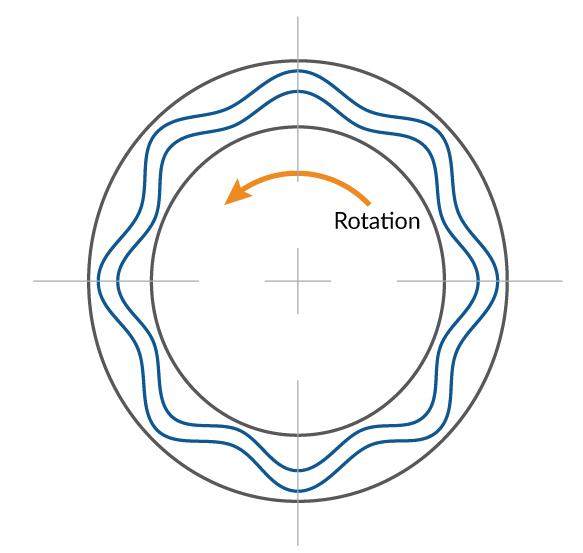
Another motor type, the piezo motor, deserves an honorable mention because 'very small' has always been its bread and butter operating domain. Notably, it does not use magnetics to generate torque. Instead it takes advantage of the tiny dimensional change of piezoelectric materials when subjected to an electric field. Utilizing this principle rotary piezo actuators carefully excite the rotor disk to set up a standing wave whose phase can be changed electronically. The stator is effectively a very low-height gearhead that 'grabs' the rotor once the standing wave has been created. When the phase of this standing wave is altered, rotation occurs.
Functionally, piezo motors most resemble step motors. They excel at holding position or moving at relatively low speeds. Like a step motor they do not require an encoder to accomplish this. However, the electronics used to drive piezo motors do not resemble step motors at all, containing very specialized circuitry to generate the standing wave and control its phase.
So far Piezo motors have seen high volume adoption in specific consumer applications such as camera auto-focus and f-stop control, and modest levels of adoption in niche applications such as ultra-high precision XYZ tables and pointing.


But given their ability to be produced in very small form factors (2 mm x 2 mm x 5 mm or even smaller), and given the larger trends in the medical/robotics world toward smaller motors, it seems a fair bet that we will be seeing more of piezo motors in the future.
Can we switch?
The single most important change driving the remarkable size reduction in electronic motion controls are the performance of digital switching amplifiers, most o en MOSFET switches. These ICs, which when first introduced were prone to failure, prone to overheating, and prone to being large, can now switch with 98%+ e ciency, are extremely reliable and have shrunk to remarkable densities.
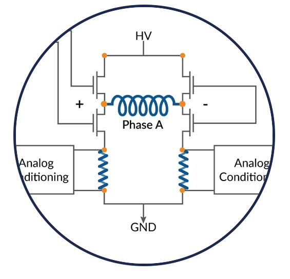
How can a binary switch command a continuously changing output voltage? While it may seem counter intuitive, modern motion control amplifiers do not literally ampli anything. They 'ampli ' by entirely connecting, or entirely disconnecting (switching) the motor leg to an HV supply voltage or a GND connection.
PWM (Pulse Width Modulation) schemes ensure that an analog command signal can be represented in this digital all on/all off scheme. For example, to present an average of 37.3 volts to a particular motor coil with an HV voltage of 64 volts the PWM output will connect the HV 58.3% of the time (37.3 / 64 = 58.3%), and connect the ground the rest of the time.
Stay calm and switch e ciently
One fairly basic area affected by the drive electronics yet still quite important is the PWM drive equency. It may be that the PWM drive equency needs adjusting when changing om a bigger motor drive to a micro-sized motor. Ultimately the optimal PWM equency is determined by the motor's inductance, but that generally tracks with size. Smaller motors mean lower inductance. A significant source of chatter and heat generation in small motors occurs when there is too much current ripple coming out of the switching amplifier. In the past, a PWM equency of 20 kHz may have been typical, but today PWM equencies of 40 kHz, 80 kHz, or even higher are o en needed to correctly control these motors.
How does PWM equency impact heat generation? The answer is that a digital switching amplifier delivers extraneous energy in a saw tooth pattern for a given current command. Increasing the PWM equency reduces the magnitude of this noise inducing and heat-generating current flow, and improves the accuracy of the current measurement.
Increasing the PWM equency will somewhat decrease your switching amplifier's e ciency, but this is another area that has seen tremendous IC technology progress. MOSFETs in particular have seen big reductions in what are known as 'switching losses' - essentially a fixed loss of energy per switching action. In the past switching losses could eat up 5% or more of the MOSFET's overall e ciency above 40 Khz. With the latest generation of MOSFETs this has dropped dramatically, allowing amplifiers that switch as high as 100 kHz but still operate with 90%+ e ciency.
An interesting new trend related to this is the slow rise in the use of a new switch semiconductor material, Gallium Nitride, o en called GaN for short. Traditional switchers are made om Silicon, but GaN outperforms Silicon at higher equencies when it comes to a reduction of switching losses.
While not yet common for use in motion control amplifiers, improvements in the reliability and manufacturing yields of GaN switches over the last ten years means this type of MOSFET is bound to have a growing impact on small motors and low inductance motors that need to switch at high equencies.
One thermal dagwood sandwich please Beyond improvements in MOSFET and general IC performance there has been a second, less publicized revolution happening in the area of heat flow management.
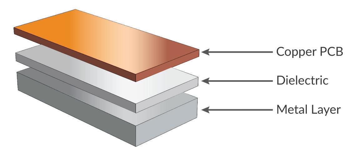
Driven by the high volume consumer LED lighting market and the challenge of managing the heat that comes om those tiny packages, a new specialized PCB, known as a metal clad printed circuit board (MCPCB) or sometimes called a thermally conductive PCB, is quickly gaining popularity for motion control amplifiers.
This technology stacks a traditional copper PCB which holds the integrated circuits such as MOSFETs, resistors, and