SUSTAINABLE
Kaizer 16059611
This Sustainable Community project introduces a proposal for live-work community. The main aim is to create conditions where the resi dents are encouraged to develop their ideas through co-working and strong social, business and educt aion support groups.
Witney, UK
COMMUNITY OF INNOVATIONS
COMMUNITY PROJECT Yuliya
COMMUNITY OF INNOVATIONS

Community of Innovations (CoI) is a group of people with the sence of comaradie, belonging and a collective identity who are jointly facilitating innovation. In the CoI the emphasis is on learning and building upon each other ’s work.
This proposal located in the centre of Witney is for facilitating life, work and socialisation of the community of innovators. It will accommodate individual living and co-working spaces that enable sharing and developing ideas and forming strong support groups.
The scheme is a mixture of private, semi-private and public adaptable spaces that “learn” from their environments and dwellers and evolve with their changing needs. It presents the viewer with two types of adaptable development - megastructure and adapt able vertical circulation modules both of which aim at a separation of building layers and enabling design that is not governed by slow-changing building components.
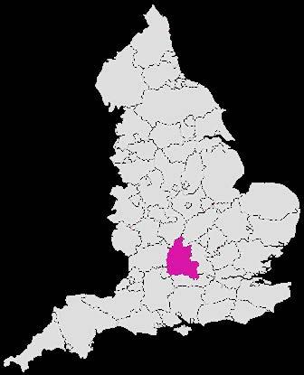
OXFORDSHIRE,UK
Witney Town Centre Boundary Church Green Policy Area
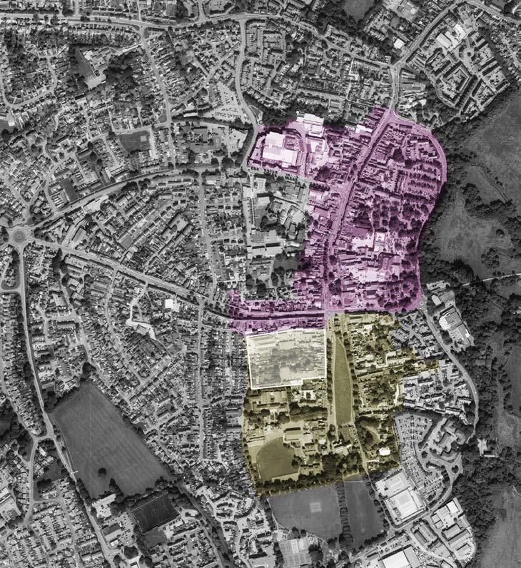
The Site (In White)
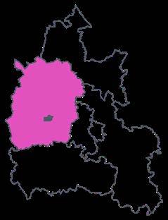
WITNEY, WEST OXFORDSHIRE, OXFORDSHIRE
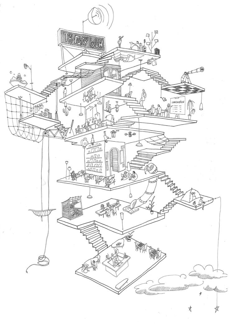
Community of Innovations conceptual sketch explodring living, co-working and socialising in vertically adaptable space (by me, Y Kaizer)
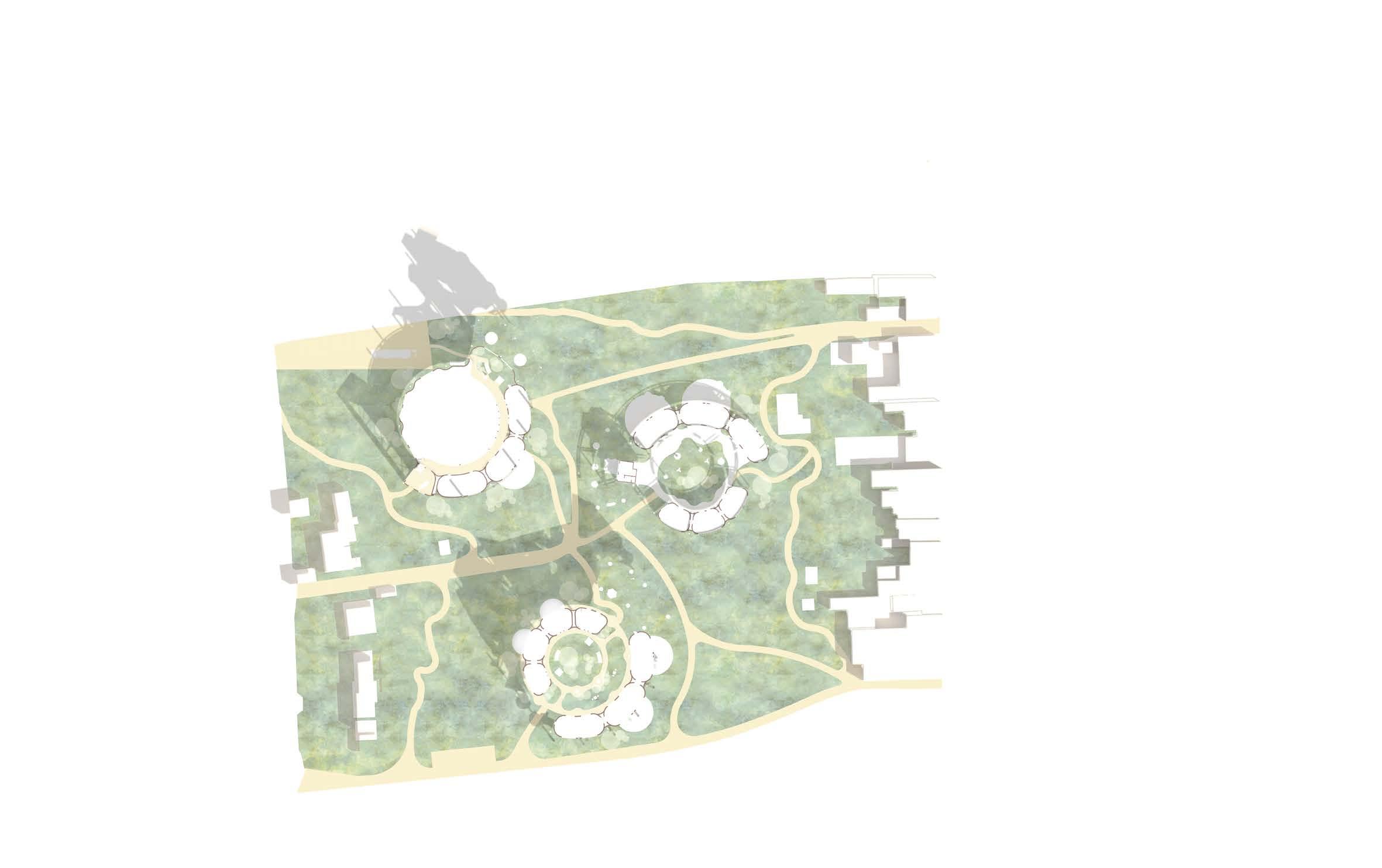
LIVE-WORK COMMUNITY OVERVIEW 1 : 5000
USER EXPERIENCE AND NEED
Community of Innovations is a space for working on innovative ideas (whether it is a product or a service). By joining a commu nity of like-minded individuals, people gain a platform for developing, discussing and realising their ideas while living and work ing on-site.
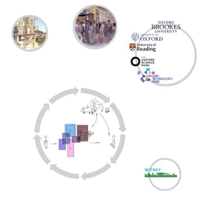
By providing new services and products Community of Innovations members will directly contribute to the economy of Witney. As a result, the inventors will get the exposure and funds to further sustain the community and their businesses. Additionally, the community development is supported by the partnering educational facilities. Educational providers are one of the biggest stakeholders of the development. They will offer academic support to the residents of the community (lectures, discussions, srticles etc.). In exchange, the universities get to use site facilities, partner with the inventors on their products and have the community residents as invited lecturers.
After members’ project (idea) is strong enough to exist on the outside, they leave the community and a new person takes their space. The newcomer will then adjust the space to their living and working needs.
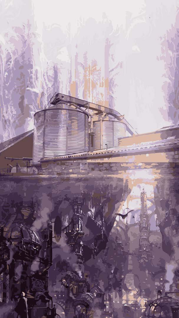
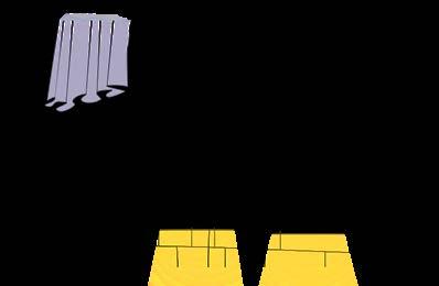
On the collage: fantasy world where living and working are unseparable and one is the integral part of the other. Top of the image is the machinery from the site in Witney. The purpose is to raise a question about the balance of living and working on the same site. What facilities are needed to bring the community members together while providing mental separation from work during leasure time?
Answer: spaces for socialisation. (by me, Y Kaizer)
 The people of community are chosen and approved by the commity members. The members’s proposal need to deliver real products and services and have a future development plan.
COMMUNITY OF INNOVATIONS USER EXPERIENCE
FOR ADAPTABILITY
User COMMUNITY OF INNOVATIONS PARTNER UNIVERSITIES AND SCIENCE PARK COMMUNITY RESIDENTS COMMUNAL SPACES Support Network User experience representation
ACCESS TO GREEN AREAS NEAR THE SITE ACESS TO CLEAN WATERAND ELECTRICITY ADJUSTABLE PRIMARY STRUCTURE ADJUSTABLE LIVING AND WORKING FACILITIES AFFORDABILITY BROWN ROOFS CIRCULAR DESIGN CLOSE PROXIMITY TO LOCAL LEISURE, HOSPITAL AND EDUCATIONAL FACILITIES COLLABORATION WITH LOCAL COLLECTIVE COMMUNITY GATHERING AREAS CONNECTION WITH HIGHER EDUCATION FACILITIES, TECHNO PARKS AND LOCAL BUSINESSES DIFFERENT LEVELS OF PRIVACY (BUILDING HIERARCHY) ECONOMY OF SCALE EQUAL OPPORTUNITIES FOR ALL IDEAS GENDER-NEUTRAL WASHROOMS AND OTHER FACILITIES
GOOD INFRASTRUCTURE IMPROVING ON-SUTE CIRCULATION INTRODUCING NEW VGETATION MEGASTRUCTURE METABOLISM MODULARITY ON-SITE BIKE ROUTES OPEN BUILDING EDGES OPPORTUNITIES TO DEVELOP ONE’S BUSINESS PRESERVATION OF VEGETATION PROVIDING GARDENING AREAS PROVISION OF OPEN AIR AND INDOORS SPACES FOR SOCIALISATION

RAINWATER HARVESTING REDUCED ON-SITE POLUTION DURING CONSTRUCTION REDUCING ASPHALT AREA REDUCING NEED FOR CAR USE RE-USE OF METAL FOR PRODUCTION OF NEW MODULES SEPARATION OF BUILDING LAYERS SITE AND LOCAL FACILITIES ACCESSIBILITY USE OF SOLAR POWER USE OF STANDARDISED DESIGN USING RECYCLED METAL FOR PRIMARY STRUCTURE
Sassi, 2006, defines sustainable communities as places that offer people opportunity to enjoy a high standard of living, while having a minimal negative impact on the environment and the economic and the social structure.
Sustainable communities should develop sustainable solutions to meet the basic needs for homes, health, education, employment, an attractive and safe environment, a prosperous economy, good public services and open space. They should be resource efficient and preferably resource-atonomous, sourcing water, energy and materials as much as possible from the local environment, as well as sourcing sources from the local community. They should also aim to be inclusive, adressing the needs of people, regardless of their background.
The biggest aim of this proposal is to make the development flexible, adaptable to future changes, including new types of activities and increasing/decreasing number of people in the community. This will subsequently feed into the objectives of inclusivity, resource efficiency through economy of scales, and other UN Sustainable development Goals.

 Collage: the collage depicts one of current entrances to the site and what can be beyond it. What will the adaptable sustainable communities look like? What is possible? (by me, Y Kaizer)
SUSTAINABLE COMMUNITY LIVING OBJECTIVES
NO POVERTY ZERO HUNGER GOOD HEALTH AND WELLBEING
QUALITY EDUCATION GENDER EQUALITY CLEAN WATER AND SANITATION AFFORDABLE CLEAN ENERGY ECONOMIC GROWTH INNOVATION AND INFRASTRUCTURE SUSTAINABLE CITIES AND COMMUNITIES CLIMATE ACTION LIFE BELOW WATER LIFE ON LAND PEACE AND JUSTICE PARTNERSHIP AND GOALS RESPONSIBLE CONSUMPTION AND PRO DUCTION REDUCED INEQUALITY
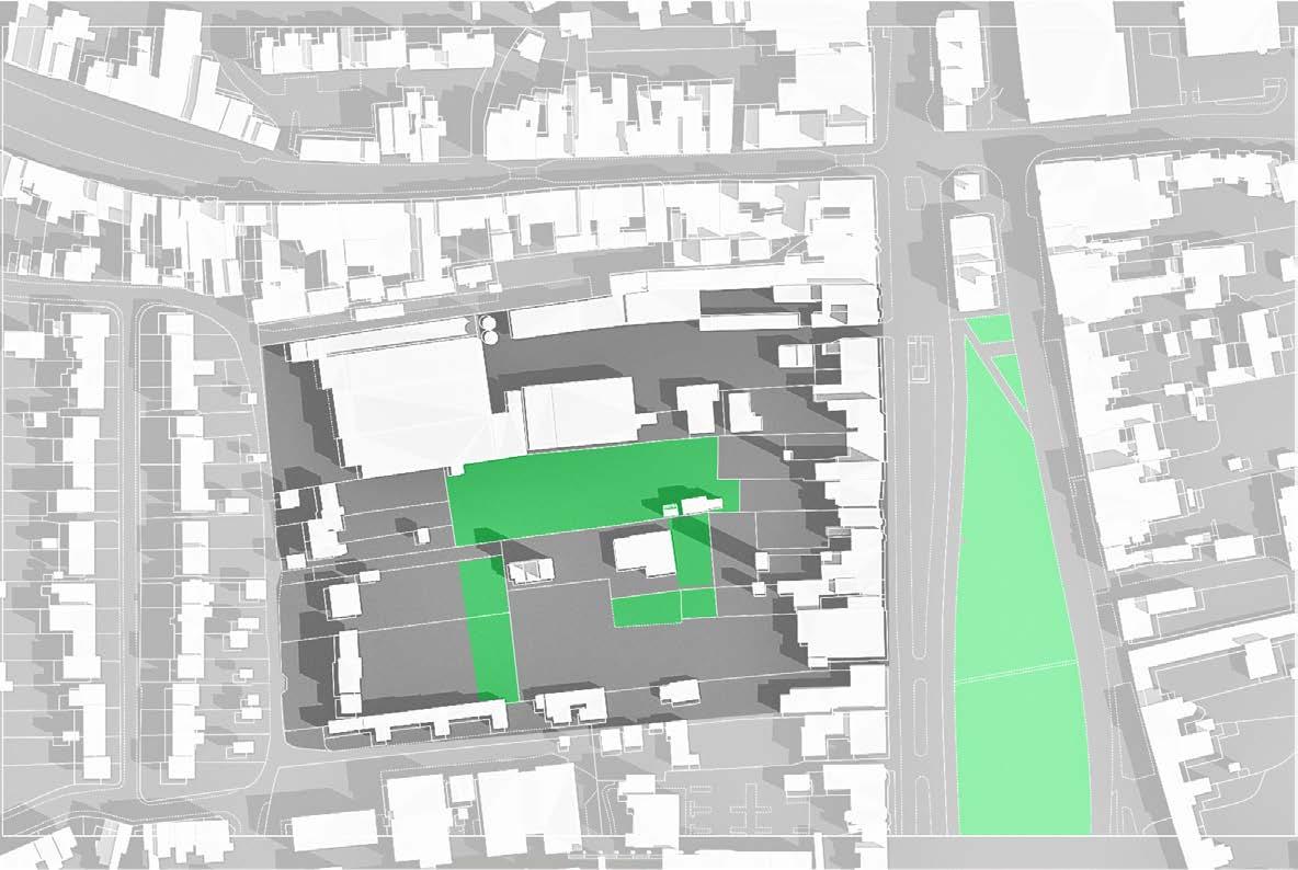
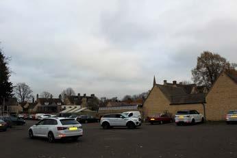
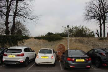
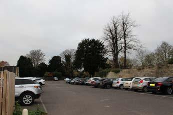
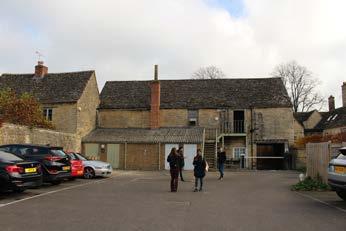
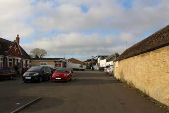
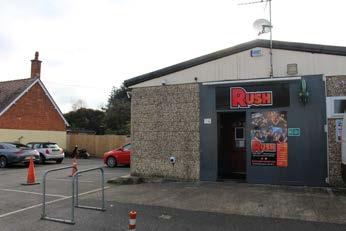
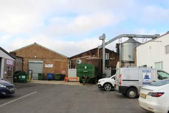
The site as it is does not have a unified building style, structure or purpose. It consists of three major zones, the Eagle Industrial Es tate, Parking lot and private gardens. The parking spaces take up most of the space, covering the site in concrete, limiting its other uses, and increasing ambient temperature. From the site visits parking lots, as well as the green areas, seem to be underutilised.
1 Create live-work community while utilising ex isting green areas for leasure purposes,

2 Utilise large parking zones for developing uni fied design for the site development,


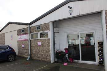
3 Use existing image of the site as a place where businesses are to highlight new “work“ function,


4 Introduce new and integrate existing business es,
5 Use a well-developed local infrastructure for living community and encourging lesser use of cars.
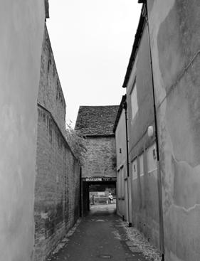
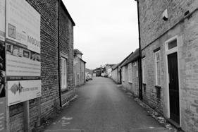
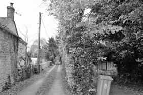
Narrow entrances to the site might potentilly make the area under-used and make it feel unapproachable
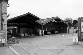
Images from the Site
S.W.O.T. Site Contents (1 : 200)
INTRODUCING THE SITE The Site Greenery Commercial Residential Eagle Industrial Estate Parking Lot Religious Parking Site Entry Points P P P P 1 1 26 7108 9 3 4 2 3 5 7 9 4 6 8 10Good Infrastructure Unstructured Spaces for Business Bad On-Site ConnectivityToo Many Parking Spac es Covering Large Areas with Asphalt Underutilised Green Areas Existing Businesses Large Green Spaces
EXISTING ON-SITE BUSINESSES
CoI takes into consideration people with existing businesses on-site. They all will be offered a place in the new development with a unified buidling style, better public access, and community facilities. The very idea of focusing on developing people’s ideas and innovations came from the current functionality of the site as a business location.
NEW IDEAS
People with new ideas come and go. They are a fundamental componene bof buiding the community. Although there is a maximum of 100 people living and working on site, the development will be designed so that the units/modules can be easily added or removed (adjusted based on number of residents/ types of ideas).
OPEN EDGES
Open edges are supported by the circular shape of the buildings, publically ac cessible ground levels, outside green areas and sitting areas outside the units, including cafes. They make the site more inviting for general public, and new and existing community residents.
PEDESTRIAN AND BIKE ROUTES THROUGH THE SITE - INCREASED CIRCULATION
Currently, due to different functionality areas and poor planning, the site does not have a walking-through circulation. This makes the site more isolated, de creasing the footfall and site exposure. By providing improved pedestrian and bike routes the proposal aims to minimise the above issues.
PEDESTRIAN AND BIKE ROUTES THROUGH THE SITEINCREASED CIRCULATION
NEW IDEAS
OPEN EDGES
NEW IDEAS
EXISTAING ON-SITE BUSINESSES
EXISTAING ON-SITE BUSINESSES
EXISTAING ON-SITE BUSINESSES
EXISTAING ON-SITE BUSINESSES
EXISTAING ON-SITE BUSINESSES
OPEN EDGES
EXISTAING ON-SITE BUSINESSES
EXISTAING ON-SITE BUSINESSES
OPEN EDGES
PEDESTRIAN AND BIKE ROUTES THROUGH THE SITEINCREASED CIRCULATION
PEDESTRIAN AND BIKE ROUTES THROUGH THE SITE INCREASED CIRCULATION
The diagram depicts multiplication of ideas to preserve life of the community (metabolism), interconnectedness, unity. It shows easy, free circulation and where people initially get attracted to the site (open edges). (by me, Y Kaizer)
PROPOSAL GENERAL STRATEGY
NEW IDEAS
NEW IDEAS NEW IDEAS NEW IDEAS NEW IDEAS NEW IDEAS NEW IDEAS
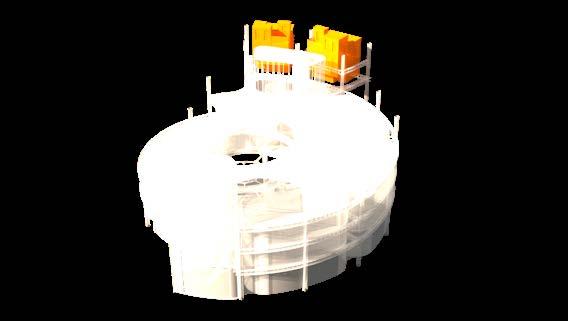
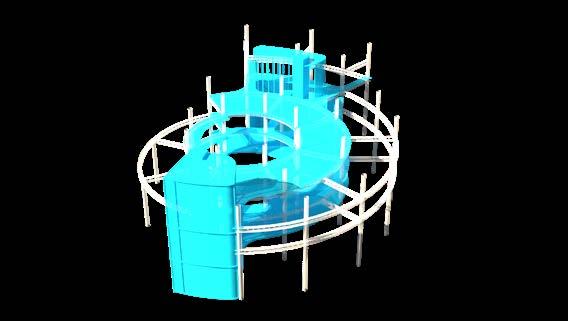
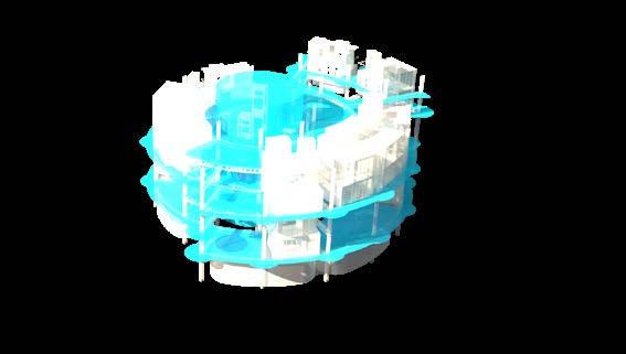
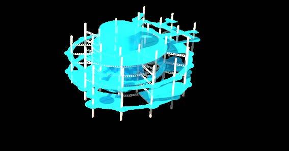
Evolving user and community needs are catered for by adaptable, inclusive building design. Each unit comprises series of living, working and socialising spaces, in addition to green areas inside and outside the buildings.
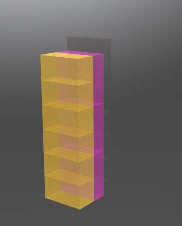
All residents will be granted free membership to the flexible work space on site (pink), creating the opportunity to work ‘close to’ but not ‘at’ home and to be part of a wider working community.
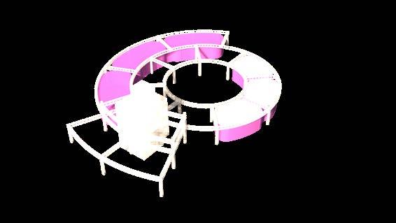
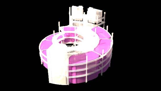
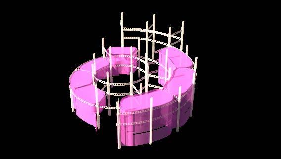

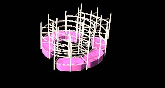
Each apartment (yellow) will also benefit from a combination of pri vate balconies and a shared rooftop garden which are designed to bring the balance into working and living side-by-side.
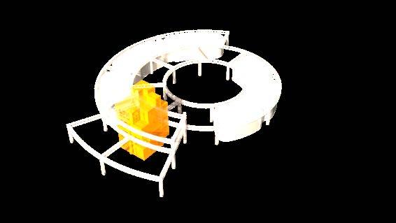


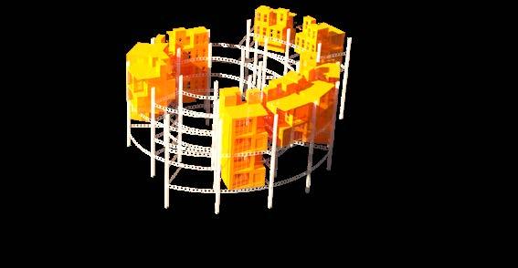
The gangways and semi open areas in transition zone provide an im portant space for casual contact with other people in the building.
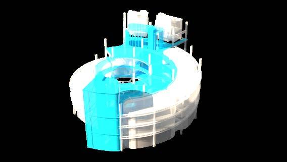
ZONING
ADAPTABLE 1. Megastruc ture 2. Modularity 1. Affordable 2. Caters for different needs 1. Spaces for work 2. Living spac es 3. Spaces for personal con tact (green areas, roof top, etc.) INCLUSIVE BALANCED UNIT 1 LIVE-WORK MODULES CONNECTING SPACESWORK-SOCIALISE MODULES UNIT 2 SUSTAINABLE DESIGN
Theory of adaptable architecture suggests that each building consists of “layers” with different lifespans. The layers change at different rates, and the more they are connected, the more difficult it is to make a building adaptable/adjustable.
The image below shows the layers diagram. The length of arrows represents the rate of change of layers. The longer the arrow, the slower is the rate of change. For example, the “stuff“ changes at a much faster rate than the “structure“.
Social - humans in and around the building that interact with and play a role in the life of the building.
Social layers could include – individuals, workgroups, departments, branches and organisations.
Stuff - components/objects that reside inside the space people inhabit.
Space Plan - components that enclose the spaces users inhabit.
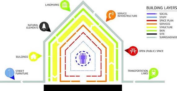
Services - components that supply and transport energy, water, communications, elevators.
Structure the primary components which support transferring of vertical loads and horizontal brac ing.
Site - the legal boundary in which the building sits.
Surroundings - the larger physical context in which a building sits, outside of its specific lot bounda ries, comprising both human-made objects and natural geographic conditions.
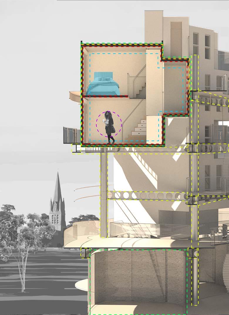
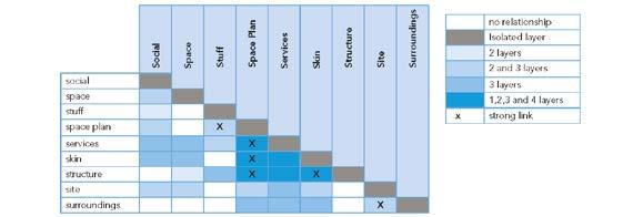
The project proposes separation of the most strongly linked layers (highlight in the table) by introduc ing megastructure. It enables separation of skin from the structure (GL), services from the structure, skin from space plan (GL by providing open spaces that can be turned into smaller units).
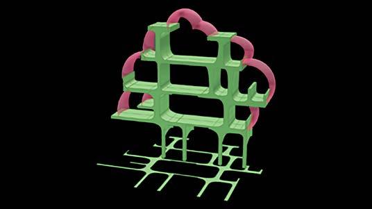
The image is showing proposed building layers and spaces that provide convertible and scalable change. The area in green is a live-work module. This, as well as the primary structure (traced in yellow) ensure scalability by providing abilitry to expand sideways and upwards. The areas in pink ensure convertibility due to flexible layout and open floor plan.
SCALABLE CHANGE CONVERTIBLE CHANGE
Change of Use Change of Size
To sustain the user and site programme, this project focuses on two types of adapt able architecture - convertible and scalable change.
Convertible change is promted by alterations in social demands and occupan cy. With every new dweller there are changing working demands depending on the type of project they are working on. Therefore the size of workspace might change as well the layout. Additionally, depending on the number of people, the same convertible spaces can be used for either working or socialising. The primary composite beams and hollow wide columns provide a space for services to run independently from the rest of the layers, increasing the capacity for multiple conversions
Scalable change is promted by increasing or decreasing number of people in the Community of Innovations. The modular nature of livework units benefits easy replacement in the future. Lack of load-bering walls attached permanently to the primary structure, foundtion pads and the ese of removing exterior walls and windows increases capacity for the scalable change.
LAYERS SEPARATION AS A RESPONSE TO ADJUSTABILITY OBJECTIVES
COMMU NITY OF INNOVA TIONS
Design Tactics for Building Layers (Self-developped) Distribution of Relationships Between Building Layers (form Shmidt & Austin, 2016) Building Layers (form Shmidt & Austin, 2016) Building Layer Design Parameter Tactic Examples Wide spans 7 - 11 m High storey height (GL) 4 m Prefabricated members Live-work modules, concrete slab walkways Skin Façade Demountable, standardised Zoning User and area control Access Exposed, clear zones Partition walls Demountable, non load bearing Exterior walls Adjustable, demountable Space Room Standaardisation Structure Services Space Plans
Architectural metabolism allows for dif ferent rates of development of parts of buildings and cities. It separates parts that change frequently, from parts that need to be preserved or don’t change at all. The idea behind metabolism is that a system can grow and transform by being flexible in its connections

Metabolism was first implemented by a collective of Japanese architects, Kikutake, Asada, Kawazoe, Kurokawa. It speculates how buildings can change, grow and evolve. A theoretical backbone of metabolism is to create self-sufficient, adaptable and sustainable society living in buildings that could behave as cells, multiplying and sus taining life Metabolism is the law of grow ing and living things.
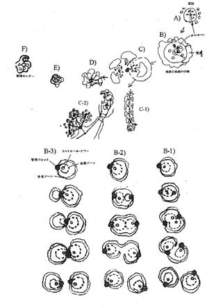
Structure. In metabolism, some parts of the buildings have to remain stationary to let other parts “grow“. Much like a tree, a megastructure of metabolic construction consists of a long-lasting structure already built and things that you can attach to it.
A Marine City by Kiyonori Kikutake introduces a plug-in system made of
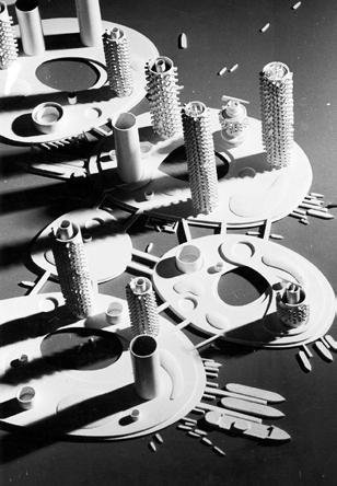
1) A Motherboard cylindrical core made of concrete that provides physical stability and supplier of all basic needs of a modern house (electricity, calefaction, drinkable water, and other things);
2) Prefab residential capsules plugged onto the core. A life span of a unit is 50 years. After that, a unit would get de tached and replaced by a new one.
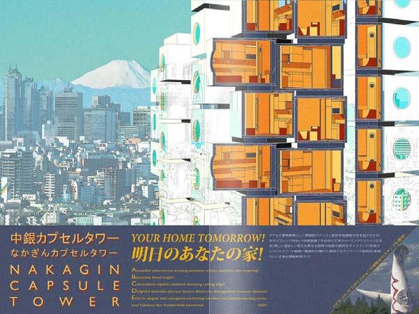
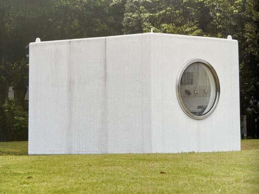
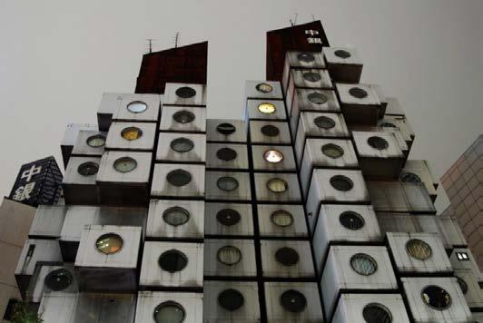
A Nakagin Capsule Tower By Kisho Kurokawa had a similar design strategy with capsules plugged into a central core. They were delivered by a track and attached to the core by a crane.
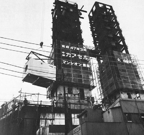
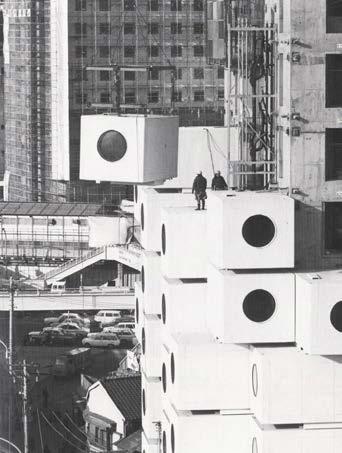
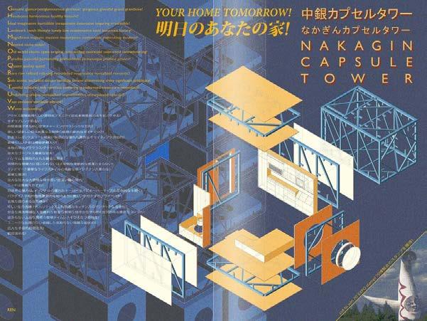
For Fumihiko Maki of the Japanese Metabolist group, a megastructure was distinguished as, ‘modular units [with a short lifespan] that at tached to a longer-life structural framework’ (Lin, 2010)
 Metabolism in Nature
Marine City Model
Nakagin Capsule Tower
Nakagin Capsule Tower, Capsule Structure
Marine City Floor Plan
Nakagin Capsule Tower, Steel Motherboard
Nakagin Capsule Tower, Capsules Attached by Crane
METABOLISM AS A LAYER SEPARATION STRATEGY: PRECEDENTS
* Please find references for the imges in bibliography under MEGASTRUCTURES
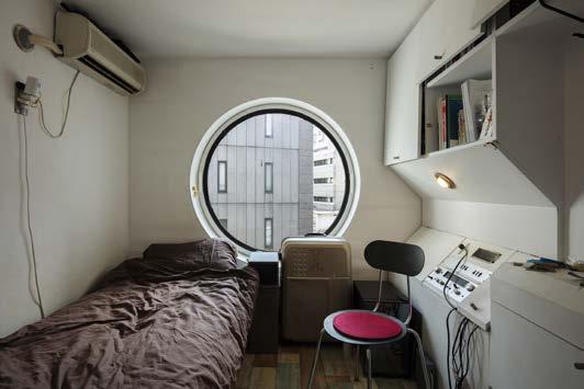
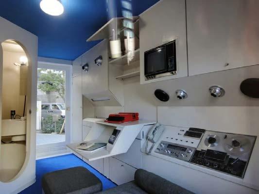
The interiors came with built-in furniture and technology.
“The tiny homes were each fitted out with built-in furniture including a bed under the porthole-style window, cabinets, a kitchen stove and fridge, a telephone and Sony reelto-deck recorder. A small bathroom even contains a tiny tub” (Block, 2021).
WHY DID IT FAIL
Poor maintanance


Capsules never got changed due to the com plexity of capsule design and no unified simi lar system.
Layers inside the capsules are too intercon nected, therefore not very adaptable. For example, the change rate of inbuilt electronics is faster than of the capsule, making it hard to update the interior without major works.
Problems with ownership and funding
“Kurokawa’s vision was that each capsule could be rotated out and replaced every 25 years, to keep the building fresh, but prob lems with ownership and funding meant this never came to be” (Block, 2021)
“Contrary to Kurokawa’s initial plans, the capsules weren’t given the overhaul they were due in 1997. In fact, the building has been poorly maintained in the five decades since its construction, with no hot water since the pipes burst in 2010 and several capsules abandoned with mould and mildew in the walls. If that wasn’t bad enough, there’s the unresolved issue of asbestos, which was com monly used as an insulator for construction in the 1970s” (Steen, 2022).
 Pen Sketch/Photoshop Sketch Idea of Megastructure Units (by me, Y Kaizer)
Rhino Representation of Megastructure Units (by me, Y Kaizer)
The sketch idea for the development of community unit uses the plug-in system introduced by Japa nese architects. The “motherboard“ structure will be made of steel and have module attached to it.
technology Photo
by DickJohn
technology Photo is by DickJohnson
ANALYSIS OF MEGASTURTURES: NAKAGIN CAPSULE TOWER, JAPAN
TAKING IDEA ON BOARD 20/06/2022, 23:01 Nakagin Capsule Tower to be dismantled and given to museums https://www 6 22 The interiors came withbuilt in furniture and
is
s Ton he interiors came withbuilt in furniture and
METABOLISM AS A RESPONSE TO ADJUSTABILITY OBJECTIVES
For the Japanese, Metabolism re-established links to traditional con struction concepts such as prefabrication, modularity, circular growth and renewal. These concepts support the separation of layers and adaptability/adjustability of the whole development.
The structural system of the megastructure consists of standardised and interchngeable parts (beams, beam connectors, columns) that are bolted together. This parts is what helps the building to grow and offers structural flexibility, durability, and reusability.
Initial Sketch of Structural Metabolistic Growth

Equal Spacing Be tween the Circum ferences (7m)
The open ends of the structure is where the mod ules do not need a beam to support them. The beams can be added later to expand the width of a unit.
Single Level Structure with Guidelines for Column Placement (1:500)
Maximum Development of the Structure on Site (1 2000)
Maximum Potentilal Development of a Single Unit with Column Placement (1:500)

Ground Level (GL) Structural Develop ment Lines 1 : 2000
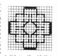
Doctrine of Durand Grid System and the Grid System for the Community of Innovations Units
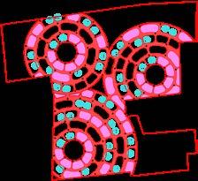
The Footprint of Maximum Development (In White) 1 : 2000
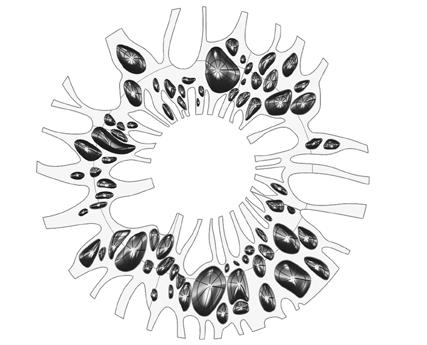
GL Development Pattern with Walkways in Red, Modules in Blue, Collumns in Black & Social Spac es/Adaptable Spaces in Pink 1 : 2000
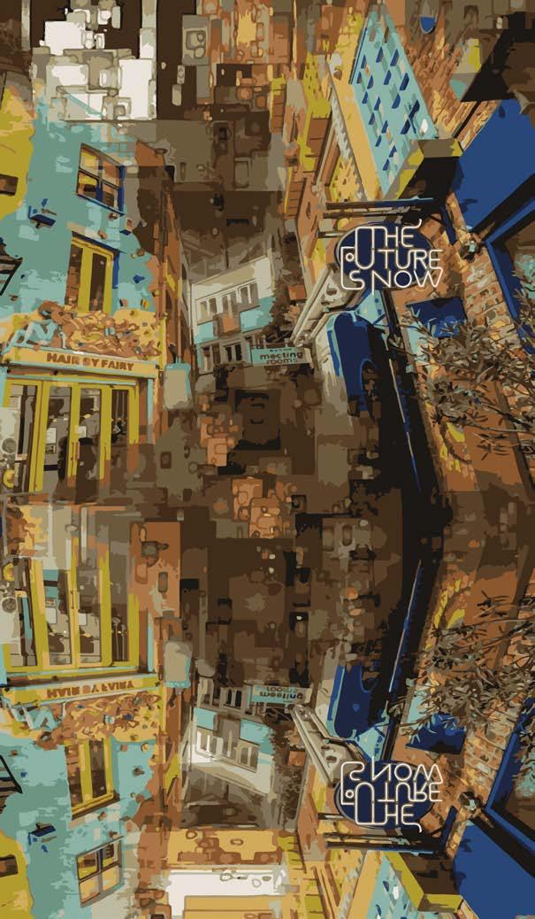
On the collage: Mirroring, multiplication, metabolism. The vision of the development as a vibrant communi ty with new and growing opportunities. (by me, Y Kaizer)
Megastructure architecture aimed to remove the static theory of functionalism and embrace social change by enabling organic growth through society’s evolving demands (Sharp, 2005).
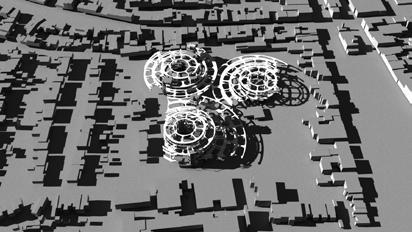
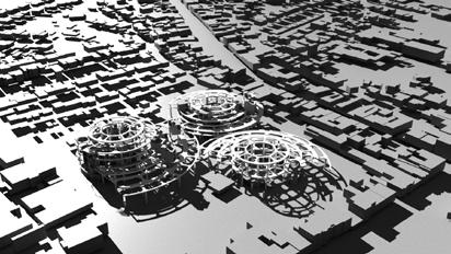
The grid for columns is based on the Doctrine of Durand Grid System. They are equally spaced within each “circumference“. The addition of “circumferences” is the addition of next row of columns and beams.
 GL Structural Development 1 : 2000 Render of Site With 2050 Development Scenario
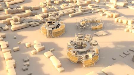
Render of Site With 2050 Development Scenario
Site Area Permitted Construction Development Area Development Simulation
ESPLAIN WHAT HAPPENS AT THE EDGES - SHOW THE BUILDING EDGES ESPLAIN AIR AND LIGH PRINCIPLES
BENEFITS OF LIVE-WORK COMMUNITY
1. Reducing distance between home and work
Time and quality of life improved by having more flexi bility by freeing up travelling time.
Infrastructure in the area 1:5000
The site is located in the centre of Witney where good infrastructure means lesser need in using cars and, as a result, fewer CO2 and noise pollution
2. Creating a cohesive, vibrant community
Having on-site and near site supporting facilities (e.g. cafes, libraries, meeting spaces) attracts people and supports social interactions, helping to bring peopele together and countract the isolation sometimes experi enced by home-workers.
STRATEGY
To provide a mixed use communal development combining work, on-site and close off-site retail, leisure and living accommodations.
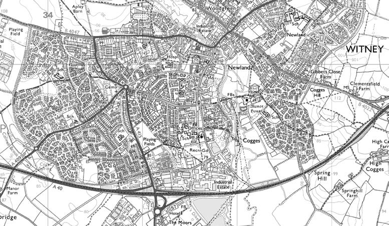
Community of Innovations - is a live-work community. By being in the centre of Witney, the community residents will get a good access to local facilities, including shoping areas, healthcare, and schools. Well developed bus routes and cycling roots around the area provide easy access to other parts of Witney and cities saround Witney, including Oxford and London. The map on the right illustrrates infrastructure near the site.
Bus stop
Healthcare facility
Learning facility/Library
Designated cycle path
Quiet roads
Urban area roads (30mph)
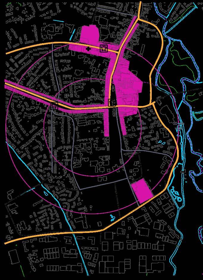


Shopping Area
The site
Private living modules
This is a stackable prefabricated module that has a vertically connected open space inside that allows residents to adapt their living space by us ing spaces for various purposes, including home offices.
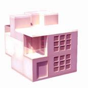
Co-working and/or socialising modules
These modules are formed by attaching pre fabricated building parts to the megastruc ture directly, allowing control over the size of the enclosed space. The co-working spaces are open to general public and to partnering educational establishments to hire.
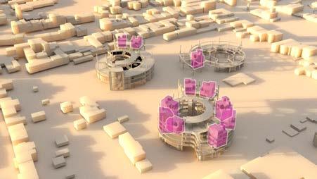 Living and working units possible location within the units
LIVE -WORK COMMUNITY LOCAL AND WIDE AREA STRATEGY
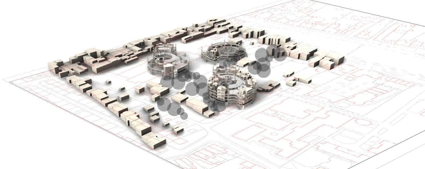
This page presents the location and initial size of community units. Units’ functionality and location are designed in a way to bring com munity members together and integrate wider Witney community with the on-site innovators.
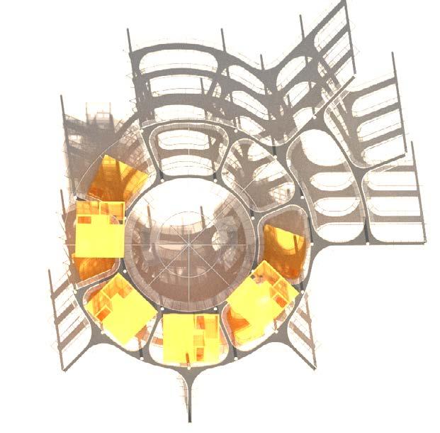
On the image: Superimposition of existing site (2D plan) and proposed development (3D Model). This view was selected as it opens a better observation point on proposed changes.
The community units consist of adjustable vertical circulation modules for living and working and simpler modules for socialis ing and co-working
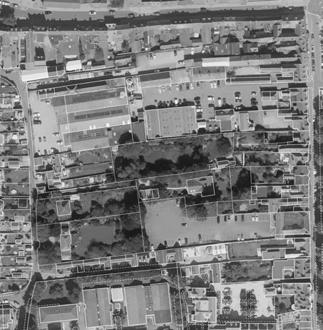
This is a community focal point where all members gather to pres ent their ideas and sell their prod ucts. Marketspace is intended to bring members of seprate commu nity units together as well as open up the area for the local Witney community
COMMUNITY UNIT # 2 LIV ING-WORKING UNITS FOR BUSI NESSES AND INVENTIONS THAT NEED TO BE OPERTED IN LARGER TEAMS
COMMUNITY UNIT # 1 LIV ING-WORKING UNITS FOR MIXEDUSE MODULES FOR BUSINESSES AND INVENTIONS THAT CAN BE OPERATED BY A SMALL TEAM
MARKETSPACE COMMUNITY GATHERING AREA/ LIVING-WORKING UNITS
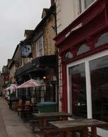
EAST FACADES IMPORTANT EN TERING SIDE TO THE SITE. MOSTLY GRADE II BUILDINGS THAT CON TRIBUTE TO SITE CHARACTER
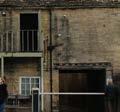
SITE VEGETTION


THE COMMUNITY DEVELOPMENT MOSTLY PRESERVES AND UTILISED EXISTING ONSITE VEGETATION OPENING IT UP TO THE PUBLIC.
At the moment, the trees and green areas are not accessible for general public. Opening these spaces up will encourage community gatherings and provide on-site green areas where residents can spend time.
The photos on the left show the facades features that contribute to the character of the site. Live ly, open exteriors manifested in big windows, benches by the pub fronts, niches by the entrances.
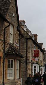
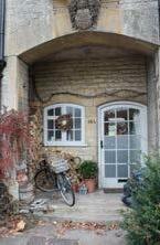
Weathered brickwork and ashlar seem to be the prevailant material.

Existing green areas that are currently underutilised and are proposed to be opened up to community members.
 EAST FACADE
PROJECT DEVELOPMENT STRATEGY: COMMUNAL UNITS
PROJECT DEVELOPMENT
THEORY: COMMUNAL UNIT SPACES. JUSTIFICATION OF UNIT LOCATIONS.


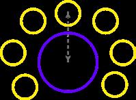
The purpose of this precedent is to map out balanced approach to livework community site structure where the socialising spaces are locted at the heart of each unit.
The Tinggarden housing project is an example of carefully considered social and physical structure. Its hierarchical division reflects and sup ports desire to strengthen the community by providing the arena for life between buildings.
The development consists of six groups of fifteen individual housing units, each with a communal building.
Private Residences
Unit Community Building (Semi-Private)
Community Centre /Gathering Pt (Semi -Public)
Transition Zone
There is a large community centre for the entire complex.
Project Community Hierarchical Structure



The social structure is expressed and supported by communal spaces, indoors and outdoors, at the various levels of hierarchical structure.
The establishment of a social structure and correspond ing physical structure with communal spaces at various levels permits movement from small groups and spaces toward larger ones and from the more private to the gradually more public spaces, giving a greater feeling of security and a stronger sense of belonging to the areas outside the private residence (Gehl, 1987, p.59).
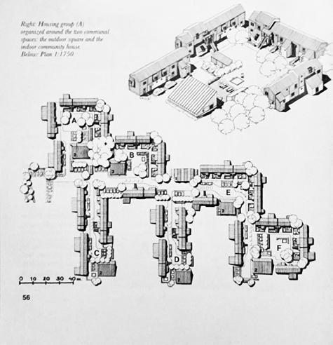
Community of Innovations Unit Concept (Right)
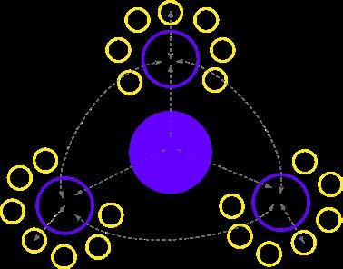
These drawings represent hierarchy of spaces on site, from public, to semi-private, to private. Unlike the precedent, yellow areas represent private residences and working spaces for members of the community.
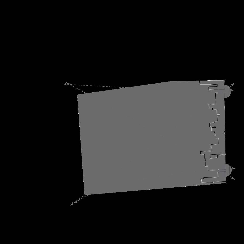
On a wider scale, the semi-private gathering area (in purple) located near the centre of the site surrounded by existing buildings and new units.
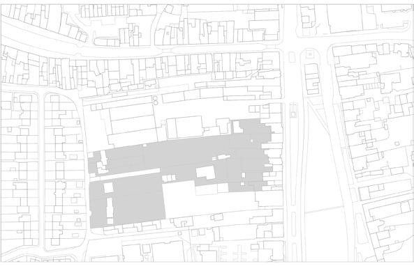
Community of Innovations Site Concept. The site in light grey. (by me, Y Kaizer)
Public
Private Community Unit
LIFE BETWEEN THE BUILDINGS: SPATIAL DEVELOPMENT PRECEDENT
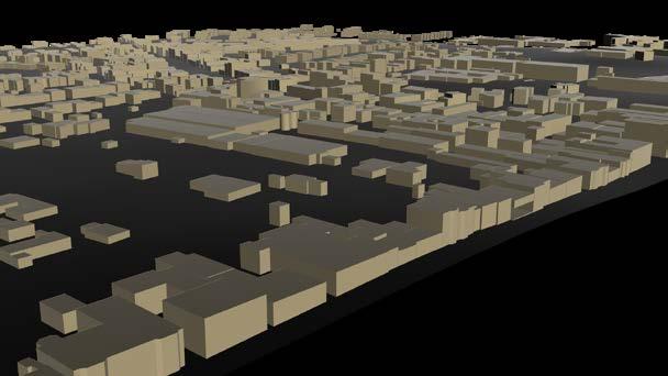
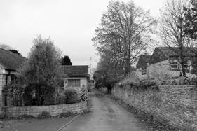
The site access strategy addresses the problem of separated and under-utilised spaces (in yellow) by unifying the area and improving pedestrian circulation. A diagram below indi cates that the site is accessible from the east and the west. However dead ends on both sides prevent an easy circulation by foot.

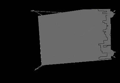


This plan below proposes a new pedestrian routes on site. A way through the site makes the Church Green area and the town centre area more accessible to the local residents living near The Crofts Road. It also increases the footfall to the site itself. As for existing vehicle ac cess, one of the local objectives is to decrease amount of cars in the town centre area. The new site accessibility will only allow access for cars at access points 1,3, & 5.
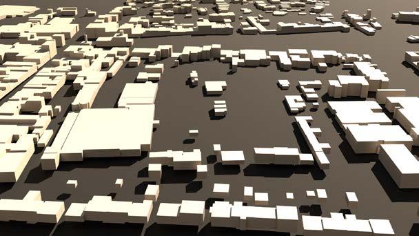
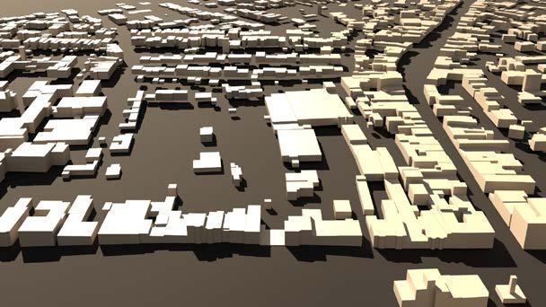


SITE ACCESS STRATEGY
1 2500 0 2 1 0 2 1 0 6 1 0 0 m A 17 2 22 8 6 Y a K e Ox o d oo e Un v s y e o n B h N a a S a e 1 0 D p © C ow p g d b e h s 2 2 O d a e Su v 0 2 2 OR DUC T O A US ON Y Public Areas Private Areas Public Pedestrian and Vehicle Acess Points and Dead Ends Site Area Proposed Pedestrian Routes Main Entry Points from the Church Green area Church Green The Crofts Town Centre Church Green Town Centre The Crofts 1 2 3 4 5 Site Access Points Views East elevation of the site. East site view (top). West site view (top). 1 2 3 4 5 1 3 5 1 2 3 45
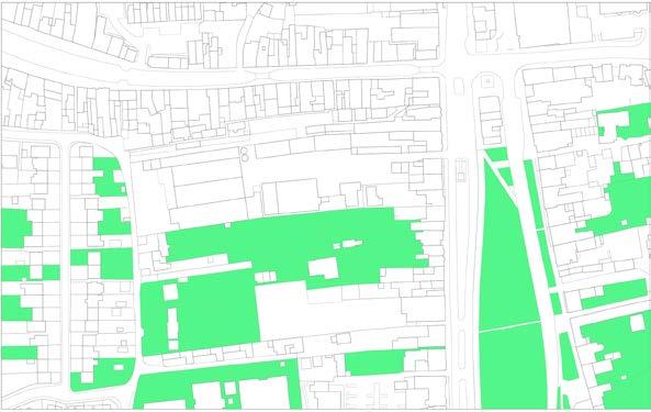
Existing vegetation (1 2000)
Existing buildings (1 : 2000)
P

P P
P P
P P P
CURRENT USE VALUE ANALYSIS
Valuable community function
Valuable architectural contribution & community function
The buildings on the site are predominantly either business related or residential. The buildings that are architecturaly important cannot be removed because they contribute to the area character. Buildings that a functionally valuable physically not as important, but it is crutial to provide space for their func tionality within the new development.
1. This is a local brewery and a feature of the site that has potential to attract the footfall within the new development.
2. These are East facade buildings that are part of Church Green character and are another important feature in attracting people to the site. Moreover, most of these buildings are a Grade II, meaning the new development will keep these buildings untouched.
3. These are small local businesses. The buildings do not have unified style or architectural value. But it is important for the new development to support existing local businesses and provide them with a space.
Traced in red are the buildings that going to be removed from the site to improve its character, use of spaces and accessibility.
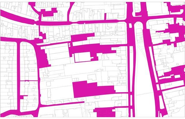
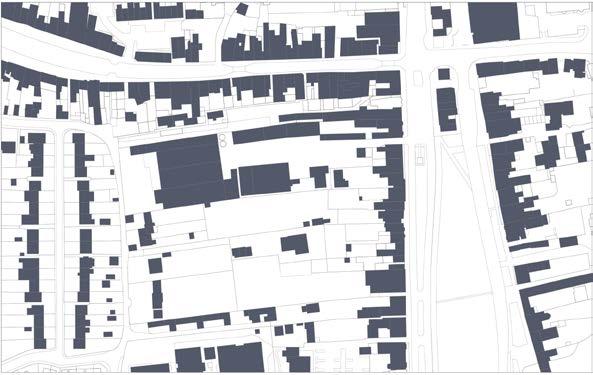

Existing site private residential areas (1 2000)
Existing Roads and Parking (1 : 2000)
SITE CONTEXT
1 23 3 3 3
and information from Westoxton, 2020 https://www.westoxon.gov.uk/

Winey is the smallest of the five-sub areas covering an area of around 7,000 hectares. However, it is the most heavily populated, containing around 33,000 people. The majority of residents (28,000) live in Witney a vibrant and historic market town famed for its association with the blanket industry. Witney is the District’s largest town, acting as the main service centre and offering a broad range of housing and employment opportunities as well as key services and facilities including retailing, health care, leisure and culture.
STRENGTHS
Property prices are relatively high (although not as high as some parts of the District) and there is considerable housing need
Whilst there are some further opportunities for housing within the built up area of Witney, these are relatively limited and to accommodate future housing needs there is a need to develop on the fringes of the town on Greenfield land.
This is the smallest of the five-sub areas covering an area of around 7,000 hectares. However, it is the most heavily populated containing around 33,000 people.
Property prices although not as high as some parts of the District are still high compared to the national average;
WEAKNESSES
This is the smallest of the five-sub areas covering an area of around 7,000 hectares. However, it is the most heavily populated, containing around 33,000 people. The majority of residents (28,000) live in Witney a vibrant and historic market town famed for its association with the blanket industry. Witney is the District’s largest town, acting as the main service centre and offering a broad range of housing and employment opportunities as well as key services and facilities including retailing, health care, leisure and culture.
STRENGTHS


The Witney sub-area plays an important economic role containing just over 30% of the District’s employment opportunities (almost 15,000 jobs) and almost 30% of the District’s economically active residents
Today the economy is diverse with a range of shopping, leisure and tourist facilities and accommodation, several small employment sites throughout the town and large employment estates on the southern and western edges. The town retains a strong manufacturing and engineering presence, and the availability of good quality employment sites on the western side of the town has attracted significant investment, including some high technology manufacturers linked to the Oxford Bioscience Cluster
Witney has the best road connections and bus services in the District context
Witney grew up as a valley settlement near crossing points of the River Windrush. The river and associated floodplain forms a significant green corridor that is an important part of the character of the town and its historic setting as well as an ecological and recreational resource
Witney offers a significant range of infrastructure including key roads, public transport, schools, health care, museum, library, sports pitches, informal open space, allotments, leisure centre and so on.
OPPORTUNITIES
Today the economy is diverse with a range of shopping, leisure and tourist facilities and accommodation, several small employment sites throughout the town and large employment estates on the southern and western edges. The town retains a strong manufacturing and engineering presence, and the availability of good quality employment sites on the western side of the town has attracted significant investment, including some high technology manufacturers linked to the Oxford Bioscience Cluster
h Witney has the best road connections and bus services in the District context
Witney grew up as a valley settlement near crossing points of the River Windrush. The river and associated floodplain forms a significant green corridor that is an important part of the character of the town and its historic setting as well as an ecological and recreational resource.
Existing image of Witney as economically important dis trict area with high employment opportunities feeds into the idea of using the site to provide opportunities for peo ple to present their ideas to local employers and increase collaboration with learning institutions.
Although there is additional business space available, much of this is already earmarked for the expansion of existing businesses rather than inward investment; new proposal will accomodate existing businesses. The new propositions will be able to partner with the existing businesses or/and work for the existing businesses.
WITNEY SWOT ANALYSIS
* Text
media/feyjmpen/local-plan.pdf
The development further contributes to the local economy by designeing new prod ucts and services.
The site utilises Wit ney’s connectivity with surrounding towns/cities through partnering with Uni versities and Science Parks in the area.
Additionally, by im proving site connec tivity by foot the city improves town-wide connectivity.
The site utilises exist ing green areas and diversifies town eco system by decreasing the amount of asphalt on the site and intro ducing more green spaces.
The site helps to reduce car use in the town centre by relying on well developped local infrastruture
By using globalised design and reusing materials, the site can offer affordable hous ing.
The site develops ver tically to save the floor area and decrease the building density.

However, if there is demand for more lving and working spaces, the sdevelop ment can be adjusted accordingly.
The Community of Innovators cooper ates with the existing businesses as well as offers them a place on site.
The programme timeline is introduced to bring changes to the site ‘one step at a time’ while engaging the existing site occupants and businesses into building new community. It is designed to allow for smoother transition and adjustment period for the site environment, people and existing and integrated programme.
PHASE 1
ERASING BOUNDARIES TO IMPROVE ACCESS; BUILD ING CENTRAL UNIT (UNIT 3) TO ATTRACT PEOPLE TO THE SITE AND CREATE MARKET PLACE FOR EXISTING AND NEWCOMING BUSINESSES.
THE UNIT WILL HAVE 6 UNITS WHERE THE BUSINESS ES CAN MOVE TO. THE CENTRAL COURTYARD WILL BE USED FOR THE MARKET.
ADDITIONALLY, UNIT 3 WILL HAVE FIRST 2 LIVE-WORK MODULES INSTALLED AND FIRST INNOVATORS WILL MOVE IN TO THE SITE.
PHASE 2
ADDING UNIT NO1 TO THE SITE PROVIDING ADDI TIONAL SPACE FOR NEW RESIDENTS AND BUSINESSES. SOME OF THE BUSINESSES FROM UNIT 3 ARE NOW WILL BE MOVED TO UNIT 1.
ALL BUILDINGS THAT WERE MEANT TO BE REMOVED ARE REMOVED. ONLY THE BREWERY LEFT. THE BREW ERY WILL BE TEMPORARILY MOVED TO UNIT 1 GL UNITIL UNIT 2 IS COMPLETE.
PHASE 3


REPLACING THE BREWERY BUILDING AND CREATING THE LAST UNIT. UNIT 2 WILL MOSTLY HAVE WORK-SO CIALISE MODULES.
THE REST OF THE PRE-EXISTING BUSINESSES ARE MOVED FROM UNIT 3 TO UNIT 2.
DIVERSE ECONOMY
GOOD CONNECTIVITY
VAST GREEN CORRIDORS GOOD INFRASTRUCTURE
HIGH PROPERTY PRICES
HIGH BUILDING DENSITY
DIVERSE LOCAL BUSINESSES
SITE STRATEGY AS A RESPONSE TO LOCAL COMMUNITY OBJECTIVES
SITE PROGRAMME TIMELINE RESPONSE TO LOCAL SWOT RESPONSE SWOT UNIT 3 (MARKET SPACE+WORK-SOCIALISE UNITS)
UNIT 1 UNIT 1UNIT 2 UNIT 3 UNIT 3 BREWERY
#3 SOCIAL SUSTAINABILITY: LIFE BETWEEN THE BUILDINGS. DESIGN PLANNING FOR DIFFERENT LEVELS OF PRIVACY AND SOCIAL INTERAC TIONS.
Social sustainability is an important aspect of the community as it is in heart of bringing the community members together while providing mental separation from work during leasure time. Social sustainability relies on social contact and communal bonds.
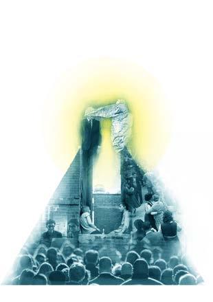
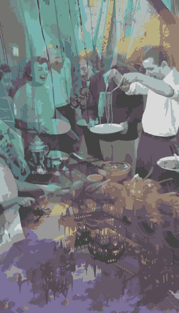
To create communities that last it is important to ensure good level of social contact and strong communal bonds that are provided by accommodating variety of activities.
There are three types of activities in public settings: necessary, option al and social. Necessary compulsory (e.i. Going to work, school); op tional - desire to do activities, allowed by favourable physical space and time (i.e walking, sunbathing, smelling flowers); social or “resultant”activities that depend on the presence of others in public (passive and active contacts). The latter two are the most important for creating pleasant living and working environment. Although architects cannot directly influence these activities, the physical environment can affect the possibilities of meeting, seeing and hearing people.
To facilitate diversity of activities the site will provide spaces for living, working, socialising in more intimate conditions (private terraces, etc) and more casual conditions (walkways, green areas, etc.)
In addition to the diversity of activities it is important to have a high-in tensity social cohesions as they make the community more lively, meianingful and socially sustainable. The intensity of social cohesions goes from passive contacts, chance contacts, to acqunitances, to friends and close friendships. This is when spacial planning and privacy levels come into play.
As such, the ground levels of the buildings should be more open and spacious to allow strangers to meet for the first time and engage with the rest of community members. This will put the beginning to the social chain by creating chnace and passive contacts.
As we go higher up the buildings in the community, the level of priva cy increases. As well as the intensity of social interactions. People are more likely to invite close friends to their private areas.
CLOSE FRIENDSHIPS
Contact intensity from low (bottom) to high (top)
Ground level public socialisation areas (garden, cafes, etc)
Co-working spaces and transition zones
Private social spaces for the residents and residential modules
IMPORTANT SPACES
People come where people are. According to Gehl, people are attract ed by activities of other people on site. This can be interpreted as fol lows: to create a strong social chain and diverse types of activities, site needs to have open places where one can be an observer; this creates initial chain link AKA passive “see and hear” contact. Public spaces
For community members contacts and various forms of activities to develop beyond the a superficial level, people need to have common interest. In this project’s case developing innovative ideas into via ble solutions. This stimulates more meaningful contacts. Semi-private spaces and private spaces.
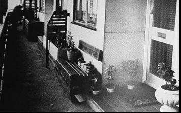
Another important feature that encourages social contact and con nects different types of spaces are “soft edges” in transition zones These are spaces outside dwellings that are easy to access; good stay ing areas directly in front of the houses; something to do, something to work with directly in front of the house.
FRIENDS ACQUAINTANCES
CHANCE CONTACTS PASSIVE CONTACTS (SEE AND HEAR)
PRIVATE SEMI-PRIVATE PUBLIC SPACES
If the edge of a public space works, so does the space. Carefully designed edge zone: a small terrace, a tiny garden, a bench by the door, and a screen between neughbouring units (Gehl, 1987, p.194)
A balcony, a niche by the entrance, a tiny bench, a small garden and the neighbours “at arm’s length“ from the kitchen window - simple but ex tremely useful details (Gehl, 1987, p.194)

The relationships between members of a community can range from superficial aqui tances to closer working co-operations. Informal relationships can be undemanding and casual and can develop through daily activities such as shopping, taking a walk or having a drink in a cafe or pub. More formal relationships may develop within community groups and voluntary organisations working purposefully towards shared goals, which often benefit the community as a whole (Sassi, 2006, p.54).
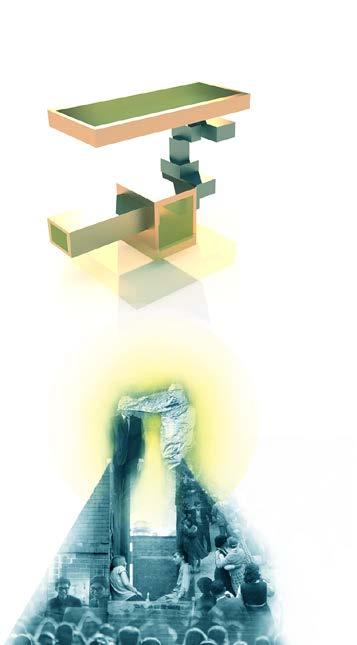
 On the diagram: How Gehl’s idea can be translated into building environment. From left to right. Social connections chain
Stage A. Visualising contact intensity in society. From passers by to close friends. (by me, Y Kaizer) Stage B. Imagining contact intensity in terms of privacy levels in a vertical develop ment (top image). (by me, Y Kaizer)
The Byker Wall, Newcastle upon Tyne, by Ralph Erskine. Showing soft edges
Collage representing the ultimate aim of this project: to create strong bonds between the members of com munity while sharing common interests and goals. (by me, Y Kaizer)
DESIGN CONCEPT
1 1 2 3 2 3
Further development inspirtion from Marine City metabolism
https://archeyes.com/marine-city-megastructure-kiyonori-kikutake/
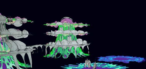
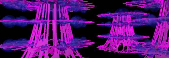
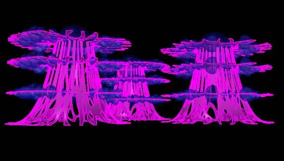
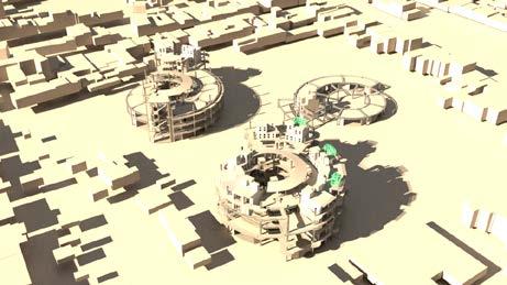
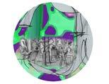
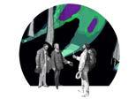
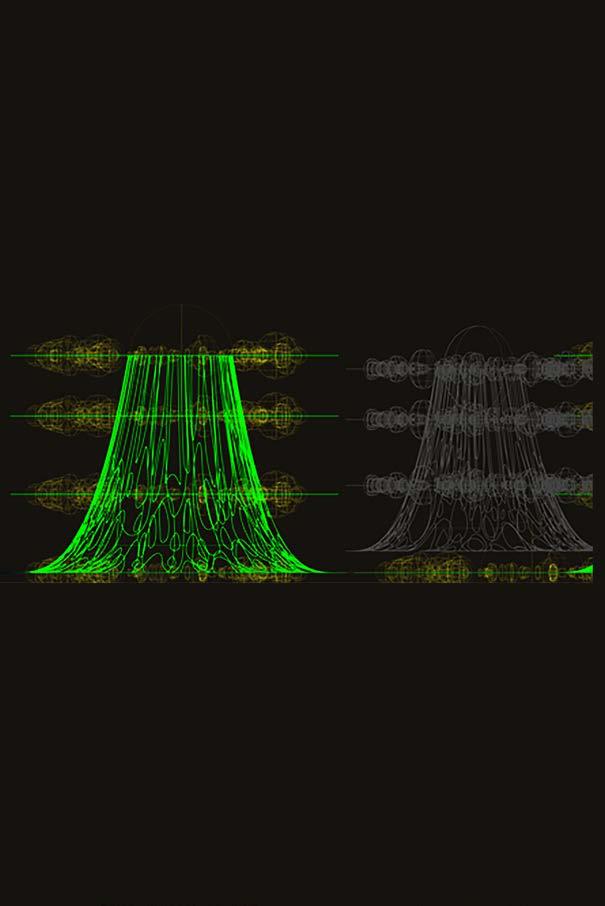
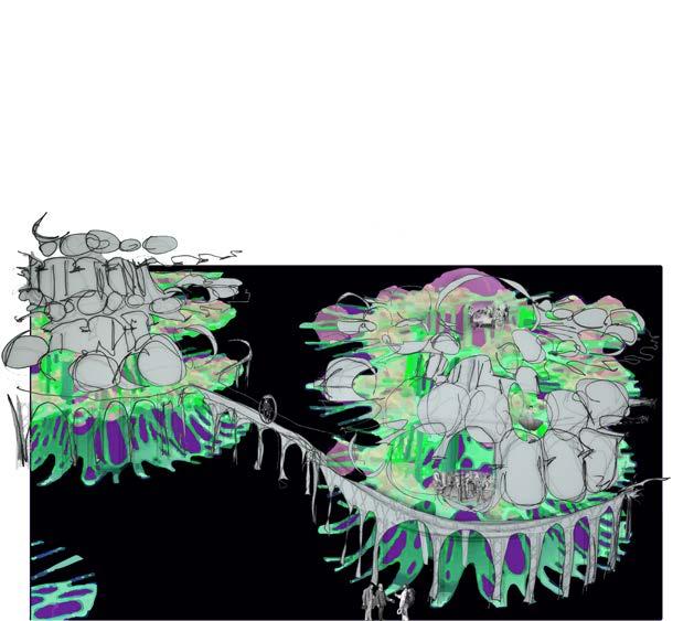
This 3D drawings and sketches were developped as a part of explortion of metabolism and vertical development. The drawings depict interconnect ed megastructures with “pod“ and the life hap pening in and around them.

CONCEPT SUMMARY
This projects aims to develop sustainable commu nity living through:
a) Strengthening relationships of community members by bringing likeminded individuals together in a setting that is designed to support desired social structure
b) Designing structures that respond to evolving community needs through metabolism
c) Creating building hierrchy tht can support and form different relationship hierarchies.
FORM FINDING
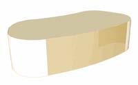
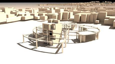
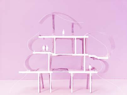
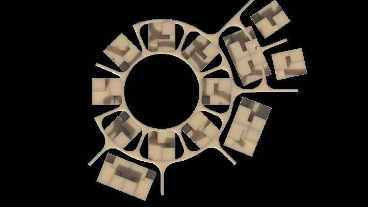
This is a conceptual 3D and a real-life model exploring vertical develop ment with tall, open ground level to make the building more inviting for public; enclosed spaces on level 1 and 2 for living and working (private); and rofftop with some wnclosed areas where the resi dents of the commu nity can socialise in more private settings (semi-private).
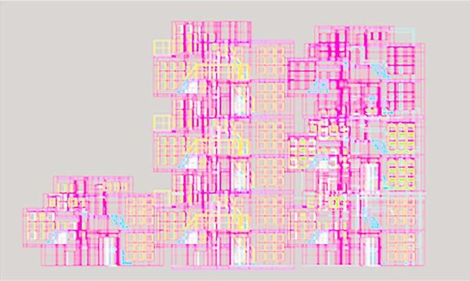
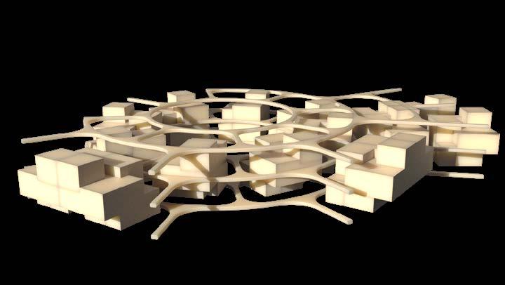
When you look up projects from this collective, you can notice some patterns. Their design style resembles the idea of a tree, at least in the relationship between trunk and leaves: a long-lasting structure of wood holds smaller and perishable units called leaves. This logic is present in most of their buildings.
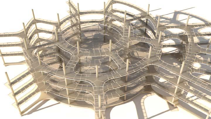
This 3D Rhino model is exploring the struc ture of the megas tructure with walk ways attached to the main steel frame of the megastructure.
This 3D Rhino model is exploring pods’ configuration on the megastructure. The purpose is for the pods to still be get ting enough air and light even when the building keeps grow ing on site.


FIRST DESIGN DRAFTS
PUBLIC EDGE: OPENING UP THE SITE FOR NEW PEOPLE
This page explores open edges as a strategy to make the site more welcoming. Even though the entrance to the site from the East is quite narrow due the row of Grade II listed build ings, the new development aims to make the site more open by
a) having open ground levels where people can go through, b) having curved edges where site furniture can be placed/greenery planted, c) having large windows on the ground levels, d) placing the most open unit (Unit 3) closest to the East site access points, e) making unit 3 a community focl point - a market space where local residents and people from CoI can come together
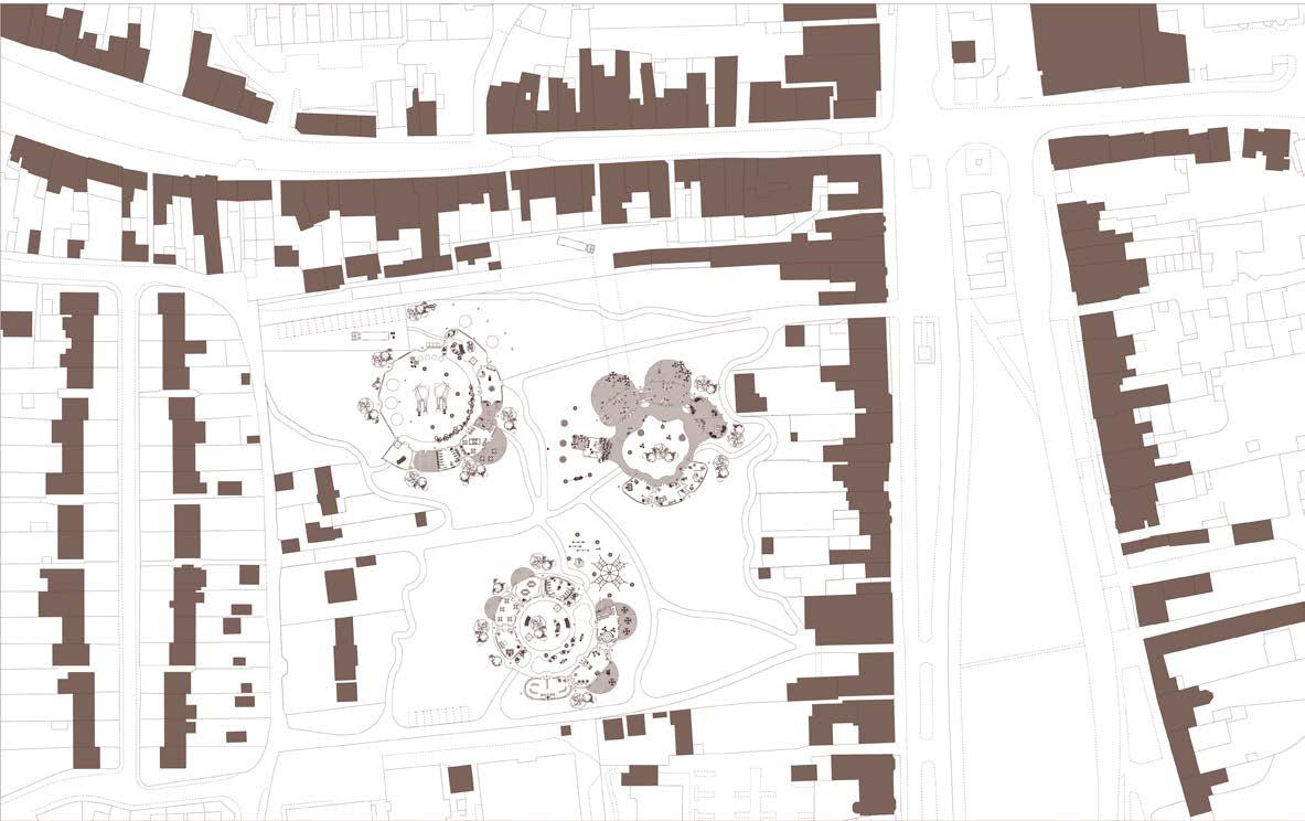
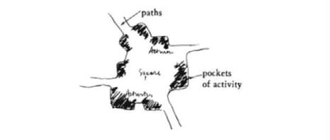
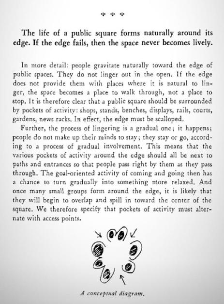
Surround public gathering places with pockets of activity - small, partly enclosed areas at the edges, which jut forward into the space between the paths, and con tain activities which make it natural for people to pause and get involved. - ALlex ander, 1997

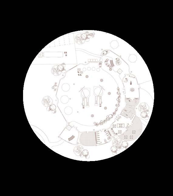
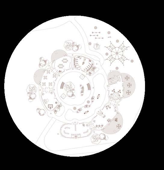
All three units aim to accommodate small pockets of life for visitors to stop for a minute, have a look around, enjoy the view, have a chat with a strnger...
UNIT 1 UNIT 2 UNIT 3
Adaptability of the development is presented within the future needs of the community (of inventors). The needs are: a) accommodation of more or fewer community members depending on the demand; b) facilities for accommodating new types and scales of businesses.
Response: Megastructures with prefabricated components and structure -independent “modules“. This enables separation of ‘shearing’ layers and decreases cost and complexity of changing the components.
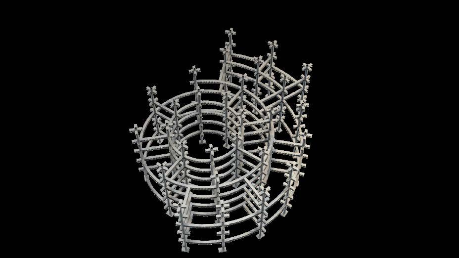
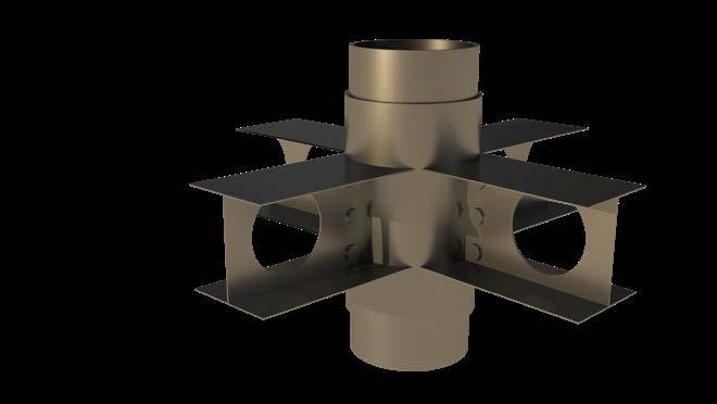
Primary structure is made of steel and comprises composite beams and round hollow-section columns. The columns and the beams are bolted together with help of the connection details, which come pre-in stalled on the columns. This way, primary structure provides adjustability for the future changes and allows for different rates of development of parts of buildings The system can grow and transform by being flexible in its connections
The primary composite beams and hollow wide columns provide a space for services to run independent ly from the rest of the layers, increasing the capacity for multiple conversions.
Each unit grows from the centre outwards. The base structure - is the central structure in each unit that has to be installed in a first place to cater for megastructure growth. Each level has pre-defined height of 3m, except ground level which is 4m to accommodate larger-scale ideas.
MATERIAL
The primary structure is made of steel as it is strong, weather and insect resistant. Steel comes to the site coated in zinc to slow down oxidising, as well as coated with intumescent paint for fireproofing. The lifespan of steel can be as long as 100 years. At the end of the lifespan of individual elements, they can be replaced or removed and sent to be recycled/re-used.
PROCESS OF CONSTRUCTION/GROWTH - COLUMNS CIRCUMFRENCE 0--> COLUMS CIRCUMFERENCE 1--> BEAMS BETWEEN COLUMNS ON DIFFERENT CIRC --> BEAMS BETWEEN COLUMNS ON THE SAME CIRC.
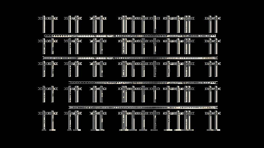

Schematic Structural Plan for Unit 1 with base structure in pink circumferens 0 in blue and cir cumference 1 in green (Scale 1 500)

Ground Level
First Level
PAD FOUNDATIONS
Pad foundations provide support for structures, transferring their load to layers of rock that have sufficient bearing capacity and suitable settlement characteristics. They can be used to help to prevent settlement.
Pad foundtions are spread foundation formed by rectangular concrete ‘pads’ that support localised single-point loads such as structural columns in this case. This load is then spread by the pad to the bearing layer of hard rock below.
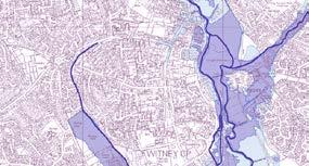
FLOOD ZONES WITNEY GROUND CONDITIONS
Second Level
The site is not in a flood zone
It is on cornbrash formation limestone (hard rock bed)
Due to these factors, the foundations of the structure can be shallow foundation which will additionally make it easier to expand the structure in the future (metabolism) with minimal disturbance to the site.
Digimap
With the top level of Shallow lime-rich soils
Rooftop
Structural layers in elevation
Structural layers view
Beam-Column-Beam Connecting Detail. Comes pre-attached to the column.
PRIMARY STRUCTURE AND CONSTRUCTION SEQUENCE
0 0 0 6 0 8 0 1 0 1 0 1 0 6 0 8 0 2000 m Yu a K z O d B S a e 1 5000
G o o c M D BG © KR 2 2 © C ow C y h a D a s h 2 2 O n n S e 1 0 5 5
Live-work modules are part of adjust able building strategy.


The modules are adjustable due to all the spaces being the same dimen sions and being equally accessible. This allows the dweller to assign rooms any functionality that they choose. The “stuff“ inside the build ing, such as furniture, fixtures and equipment, can be reconfigured eas ily to accommodate changing tasks and new people.
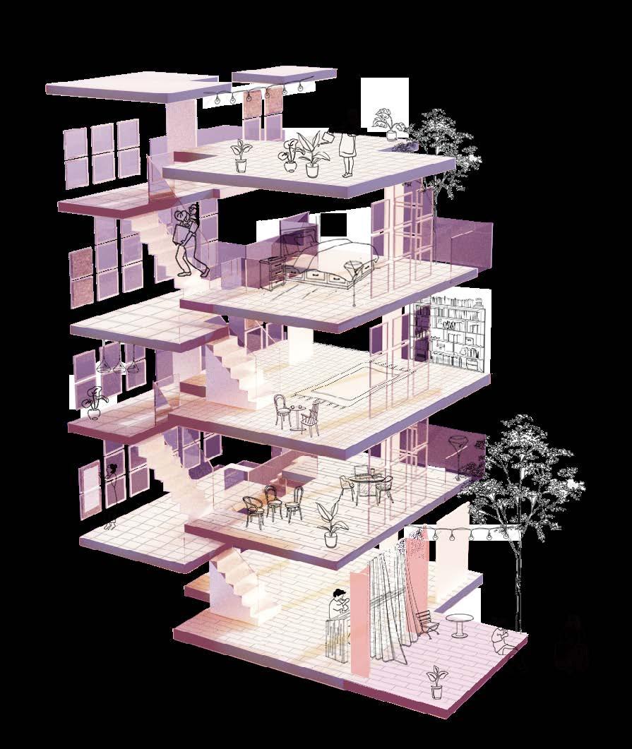
This increases the dwellers’ control over their environment.
Such adjustable strategy allows peo ple to work from home in better conditions.
Possible variation of the the module stacking where the vertical access between two modules is provided within inside. The bottom module is used as a work-from-home space, a cafe in this instance. (by me, Y Kaizer)
Other similar on-top stacking on site. The modules can either be vertically connected inside or two separate living modules.
LIVE-WORK MODULES
ASSEMBLY OF THE MODULES ON SITE
The modules are constructed from pre-fabricated parts. There are a few locations around Witney that poten tially can produce them.
Prefabrication reduces the amount of on-site pollution during construction stage (CO2 levels, noise, traffic).
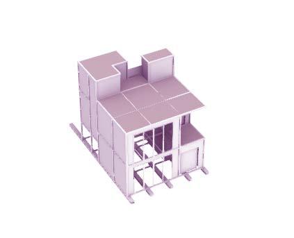
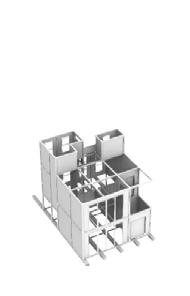
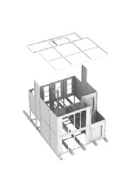
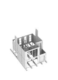
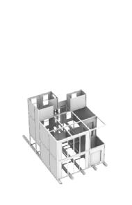
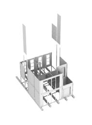
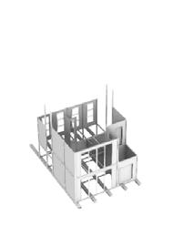
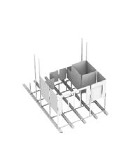
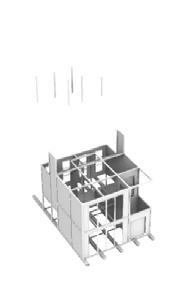
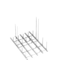
The order of construction is as fol lows:

1. I-beams installed on the general steel structure
2. Floor beams and ground-level col umns put in place
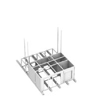
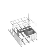
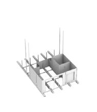

3. Wall panels are slid down between the columns
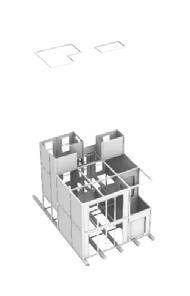


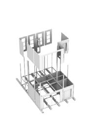
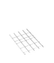
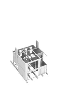
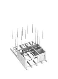
Next the process is repeated on the following levels. Floor panels are in stalled at the end.
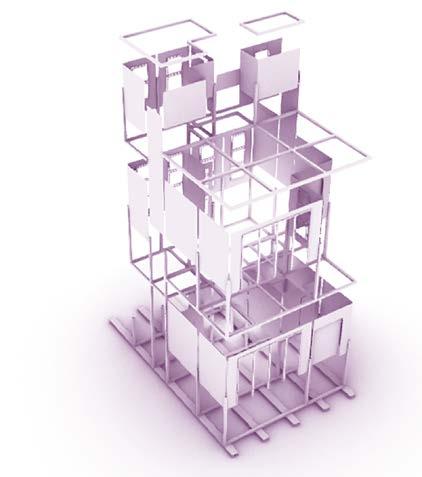
LIVE-WORK MODULES: INITIAL STRUCTURE
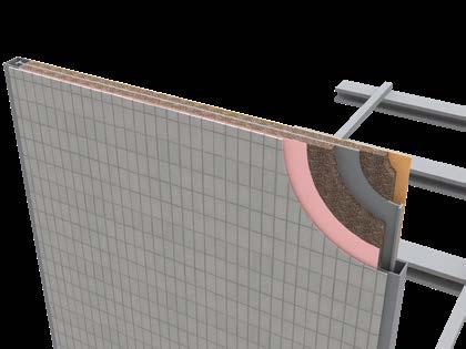
WALL DETAIL 1. External cladding 2. Breather membrane 3. Cork insulation 4. Metal pannel that gets attached to the collumns 5. Timber pannel 1 2 2 3
SPACE CONFIGURATION
The space inside the live-work unit can be devided into 3 main zones. Zone for vertical circulation, living zone, and other activities zone. This gives a different perspective on module structure and how it can be constructed.
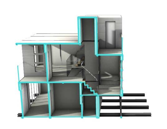
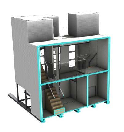

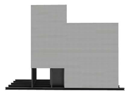
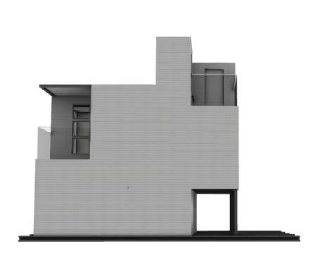
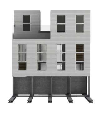
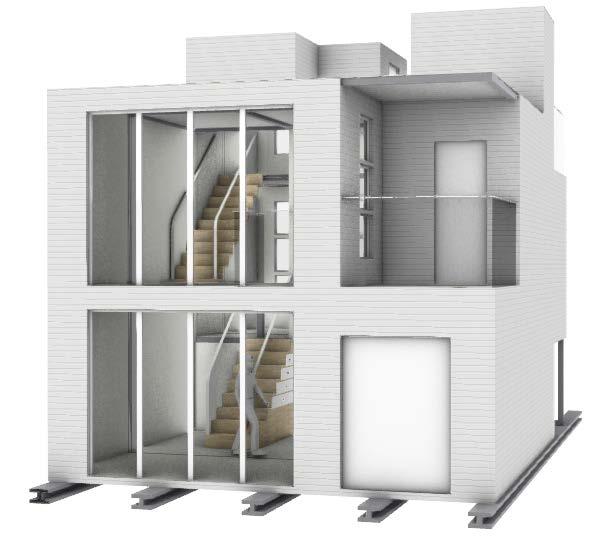
1. Perspective view on the “front“ facade of the mod ule displaying main entrance. In this case, the rooms with bigger windows are intended for facilitating main house functions (i.e. sleeping, working, living). Within the current development, the side with larger windows will face outwards to provide the residents the best possible views.
2. The “back“ facade of the module. The window size is smaller as per current development this side will be facing incide the “courtyard“ of a unit. Smaller win dows allow for more privacy.

Other Activities Zone (transition zones, kitchen, etc)
Vertical Circulation Zone (stairs, corridors)
Living Zone (Rooms)
1.
3. 1: 100 floor initial floor plans of a livework module
2.
LIVE-WORK MODULES: INTERNAL
LIVE-WORK MODULES: RE-THINKNING STRUCTURE
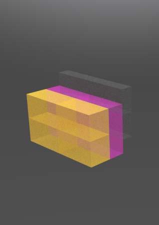
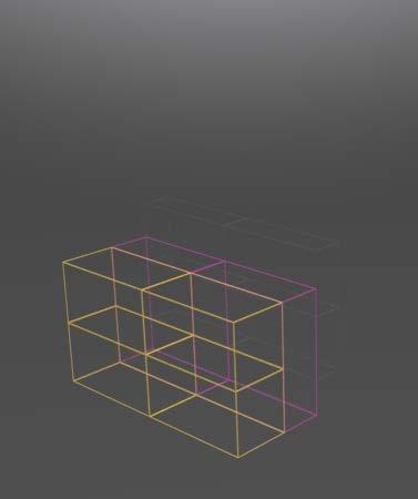
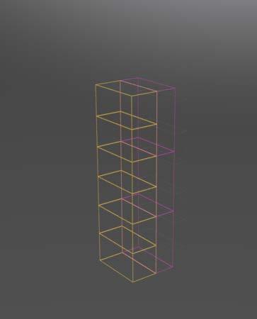
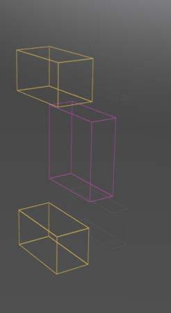

Instead of having sliding down prefab components, modular container approach makes it easier to add new modules to the structure in the future. Off-site constructed modules (containers) get attached to each other on site to form a single modile. By having standard dimensions and layout vari ations, “a ready supply of floors, roofs, corner posts and corrugated panels can be stored flatpack for a rapid, on-demnd assembly“.
Terminology: container or module = VUC (Volumetric Unit of Construction) = a building module conforming to standards for intermodal shipping, designed and engineered expressly for building construction; singlemodules = module consisting of separate VUCs that constitutes a live-work module (appartment).
SINGLE MODULE STRUCTURE.
Primary structure of a module is a steel frame.
STACKING MODULES.
Singular module consisting of smaller modules can be either stcaked on top of each other or go side by side.

All-steel lightweight structure reduces transporta tion greenhouse impact and eliminates concrete curing time (steel plate floor).
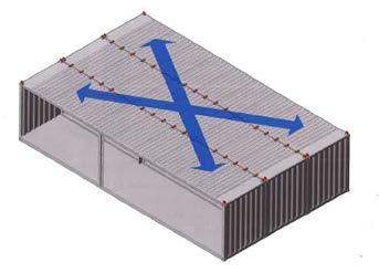
STACKING INTERMODAL MODULAR SYSTEMS
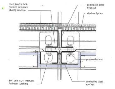
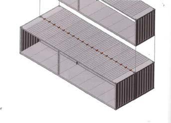
When stacking modules each with their own independent frame, it frequently adds floor thickness and wastes resources. As a solution the modules are designed to facilitate bolting of the top container rail to the bottom rail of a container stacked above, thereby creating a composite beam (Img.1). The is called “beam stitching“. It additionally helps interconnected mod ules resist wind loads to vertical trusses or shear walls (Img.2) (Wallance, 2021).
Img 1. Stacking of modules on top of one another. Beam stitching highlighted in red. Wallance, 2021
HORIZONTALLY CONNECTED MOMDULES.
Beam stitching detail. Wal lance, 2021
Img 2. Beam stitching engages adjacent containers to create a diaphragm. Wallance, 2021
LATERAL LOAD FACADE


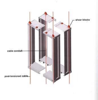
Each corner of individual container is “post-tensioned“ to another instead of bolting. A half-inch diameter steel cable is threaded through each corner from the top to the bot tom of the modular stack. Each cable isstretched tight with a hydraulic jack and locked off at 20,000 pounds of force. The post-tension cables provide the necessary resistance to wind and seismic activities (Wallance, 2021).
Tension cable detail. Wallance, 2021
Post-tension cables are an effective bracing system for mid-rise buildings for up to 6 storeys which is ideal in this case as each singular module is 2 storeys, and the max number of modules stacked is 3.
image,
The facades are rain screen facades with continuous in sulaion. Rain screens consist of opeb-jointed cladding mounted in front of a well-drained and ventilated cavity. Continuous insulation is put in the cavity, where it wraps the building shell. Behind the insulation is a waterproof and airtight barrier (Wallance, 2021).
In summer, air space between the cladding and the insula tion allows the facade to breath, ventilating hot air through the open joints. In winter, the thermal wrapper keeps the steel structure warm (Wallance, 2021)
Open-jointed, breathable walls have technical and aesthetic advantages. Open joints help to avoid maintanance issues associated with brick walls - no need to repoint mortar or replace failed sealant joints. Lighweight cladding with open joints accommodte sway movement due to strong winds on higher levels. Rain screen cladding provides a material choice freedom. In this project, timber will be used (Wal lance, 2021)
To avoid potential damage during installtion and additional expenses, facades arrive t job site pre-attached to the con tainers, ready to crane into place. After craning, unitized facade panels engage and self-seal (Wallance, 2021)
Here how it works. The unitized facade is delivered to the jobsite mounted on the module but raised a few inches above its final position to guard the horizontal joint from damage during craning. After the module is crained into position, the facade unit is lowered into position by turning adjustment screws until it has engaged its counterpart in the module below (Wallance, 2021)
Post-tension laterol load system diagram
Cable locked-off at top and botom after tensioning
Beam stitching
Post-tensioned cable
Window and Door Panels Variations (1 : 100).
Reference
online source
LIVE-WORK MODULES
As so much on the site is related to growth and development, the crane symbolises a new member joining community, or a member leaving. chose to focus on the first.
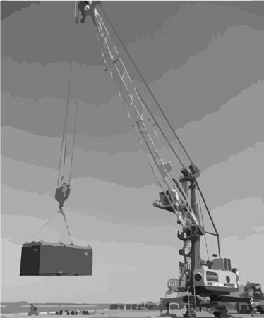
With the new buildings and crane on the background, and com munity members at the front, this collage aims to show the es sence of welcoming a new member in the community.
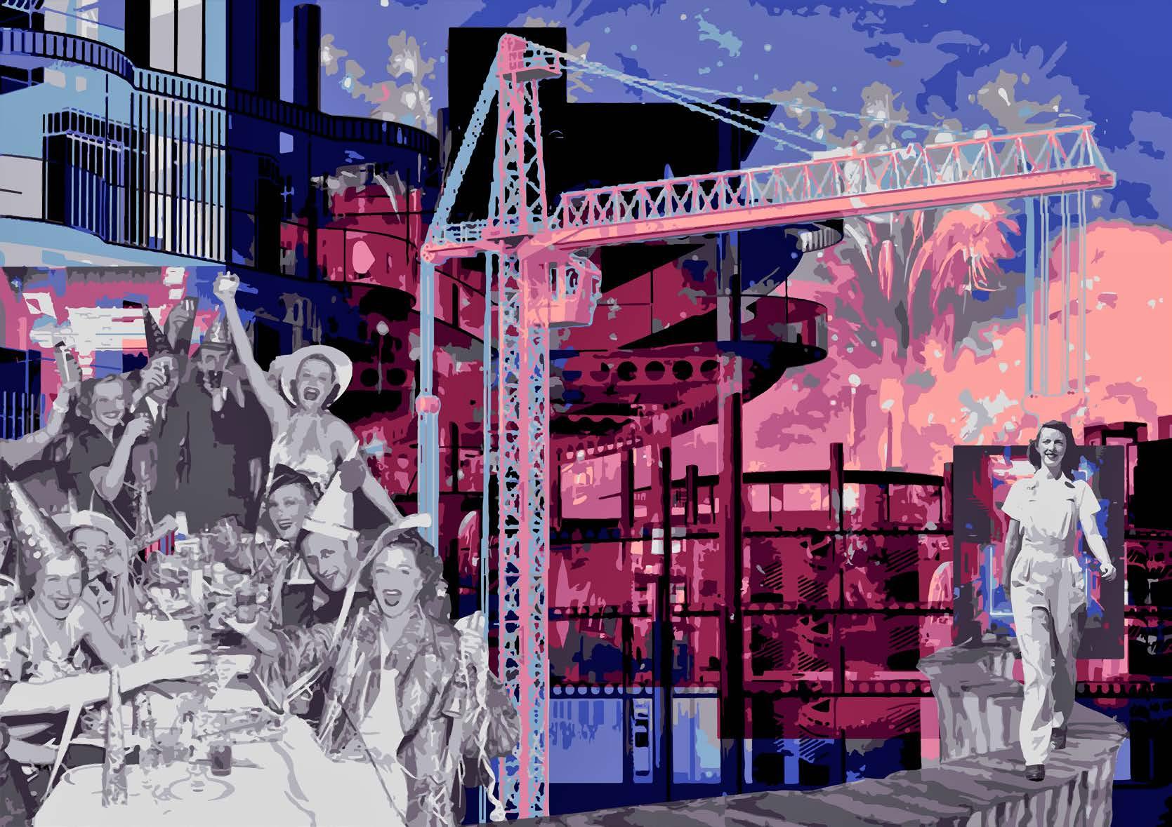 The Essence of Arrival. On the collage: The crane is a signifier of community growth, celebration of a new member joining. (by me, Y Kaizer)
WELCOME TO THE COMMUNITY
Principles of Diagoon House
Hertzberger’s Diagoon houses provide an example where the open vertical circulation allows the dweller to deter mine the number of rooms (how to divide the space) and functional uses (where they live and sleep). All the spaces are of generally the same dimensions and have equal ac cess to the service core.



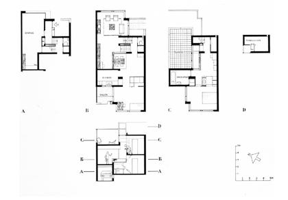
The same strategy of spatial layout will be adopted for the livework modules of CoI.
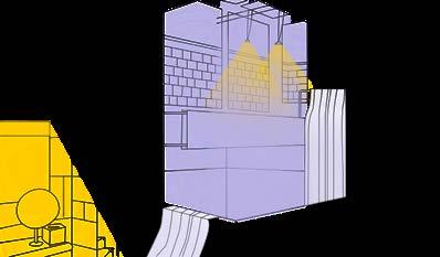

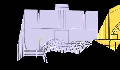
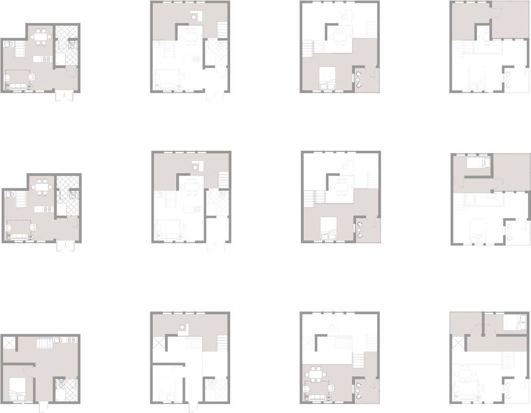
I have produced a series of Diagoon House interiaor drwaings to grasp the atmosphere. What interesting is that every space in the house is utilised. The dwellers are given the same set of spaces, but they are free to adjust them to their individual needs.
 Diagoon House section and floor plans. By Hertzberger
Kitchen Dining Area
Office Space
Bedroom
LIVE-WORK MODULES LAYOUT PRECEDENT Transition Zones
Live-work modules were designed following the study of the Dia goon House. The space caters to different needs of the dwellers by being assigned different functions..



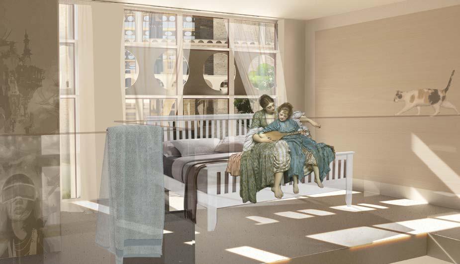
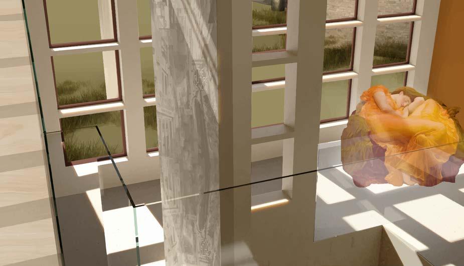 Warm summer day. Studying in the livingroom. A view on the ground level and first mezzanin level
Daydreaming. A view on transition space between GL and 1L
Music lessons. A view on the first level mezzanine
LIVE-WORK MODULES Ground Level Layout 1 Layout 2 Layout 3 1st Level 2nd Level Top Level


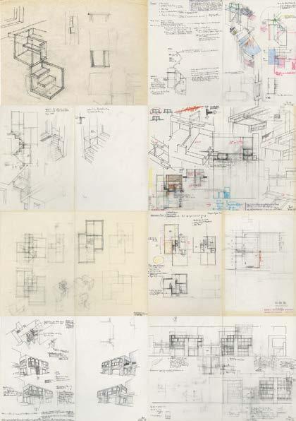


 (Diagoon House sketches by Herman Hertzberger.
Single Diagoon unit
Exploratory metabolistic renders (V-Ray)
This page further studies Diagoon House and its possible arrangement variations within the concept of metabolism.
LIVE-WORK MODULES ARRANGEMENT PRECEDENT STUDY
CIRCULAR VERSION
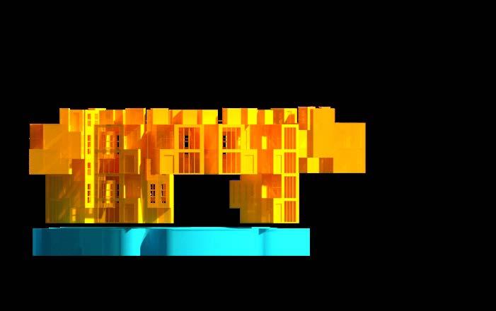
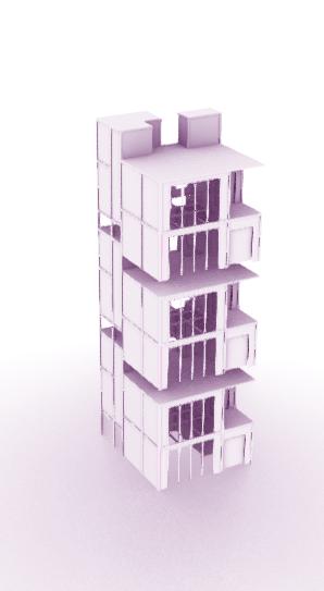
In this version every modules are stacked on one side of a unit having one-by-one pattern on the top level and skip-one on the level below. This arrangement covers the sunlight and the views for the other side of the building.



4 MODULES STACKED
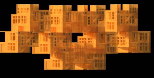
In this versionmodules come stacked on top of each other. This was aimed at being more efficient with utilizing the space. However, such arrangement made the building unit unnaproachable and with too much shading.
LIVE-WORK & WORK-SOCIALISE MODULES
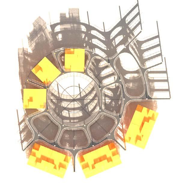
Final module configuration has 2 types of modules because having only 1 type with its relatively com plex to assemble layout wasn’t enough for all types of activities within the buildifing. The second type gave a freedom to make the ground level still get enough sunlight while providing cover if needed.
The idea is that the work-socialise modules (second type) do not have to be installed. They are only intalled when there is a need for additional working space or space for some other activity that commu nity has a demand for. Its structure is separate from the primary structure. These modules have large openings to make them being able to transform from closed spaces to semi-closed where visitors can walk through.
EXPLORATORY ARRANGEMENT OF THE LIVE-WORK MODULES
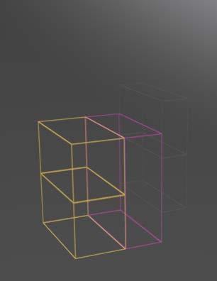
STACKING VARIATIONS FOR LIVE-WORK MODULE
Modular live-work house (steel contain er, timber rainscreen)
Section

Steel I-beams to sup port live-work mod ules
Prefab concrete walk ways
Composite steel beams (primary struc ture)


Simple timber struc ture with ashlar brick cladding to match the local character

Beam-column con nection detail (steel)
Round, hollow-section columns (steel)
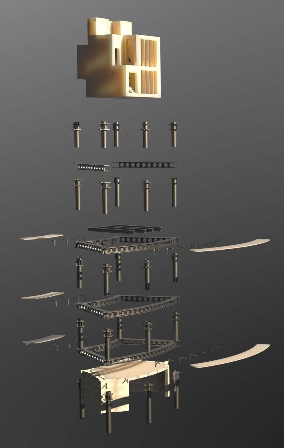
The live-work modules are installed on I-beams.
A lifecycle of the VUCs (containers) that make up the live-work modules is about 25 years with proper maintance.
This axoometric explosion drawing and section for the load path dia gram is taken as an example of the building contruction. It can be used at any point of the building with the modules on different levels and with various numbers of levels.
It constitutes a cut from unit 1 (on the right).

Unit 1. Part of a section. 1: 100.
Concrete
I-beams are bolted on the primary structural beams.
The building is affected by precepita tion, wind and occupancy load, and self-weight.
Precepitation is a live load. Selfweight is a static dead load. Occupan cy load is the weight of people and movable objects. It is a live load.
The weight of live-work modules and the precepitation is transferred to the composite beams and then to the columns. From the columns, it travels all the way to pad foundations.
All and all, the vertical load pushes the structure down causing columns to act in compression. The beams act in tension, transfering load to vertical components below.

Load path diagram for the primary structural members of megastructure that can be applied at any point of the building. 1 100.
The primary structural composite beams are bolted to columns through the column-beam connectors.
Steel brackets are bolted to the composite beams to support prefab concrete walkways panels.
Live-work and work-socialise mod ules are independent of the primary structure of the megastructure and are not affected by its weight. This supports building adaptability and growth.
The collumns are intalled first (after the pad founda tions). They come with beam-column connector at tached. This is to allow for further structural growth.
Working/socialising modules structure comes inde pendently of the primary megastructure. It can be installed before or after the colums on the ground level. On other levels, it sits on top of I-beams that are attached to the primary composite beams (much like the live-work modules).
Red - load bearing forces from the dead load of the structure
Orange - weight transferred from the secondary I-beams to the primary composite beams
Purple weight of the modules acting vertically on the primary structure/ ground
Green - precepitation load
Pink - wind force
Steel brackets
Live-work module
module
ASSEMBLY PROCESS AND LOAD PATH DIAGRAM
Work-socialise
1 2 3 4
of a single unit. Assebly order.
 A B C D E
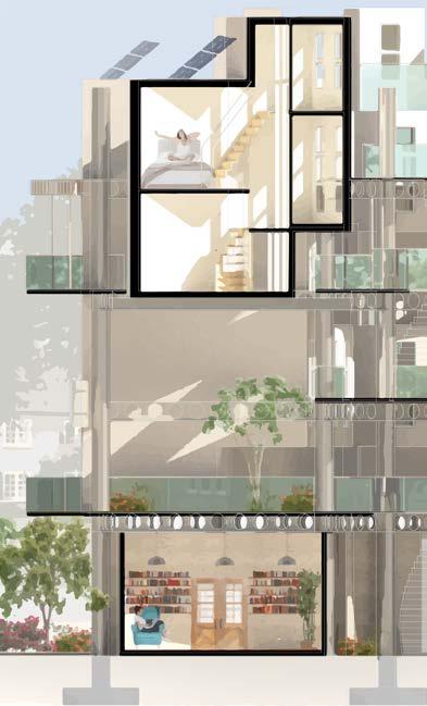
1 : 20 EXPLORATORY SECTION Here how it works. The unitized facade is delivered to the jobsite mounted on the module but raised a few inches above its final position to guard the horizontal joint from damage during craning. After the module is crained into position, the facade unit is lowered into position by turning adjustment screws until it has engaged its counterpart in the module below (Wallance, 2021) Vapour Barrier Bracing Ply Timber Rainscreen 28mm Sheep Wool Insulation 150mm Rigid Insulation 93mm Waterproof Membrane Vertical Battens 45mm Plywood Wall Board Steel Container Frame Detail B. Facade in lowered position. 1: 5 Detail C. External wall with rainscreen. 1: 5 (bottom) Weather Seals Engaged Pre-Welded Nut Bolt at 600mm inter vals for beam stitching Cold Rolled Steel Floor Rail Steel Spacer Vapour Control Plywood Board Rigid Insulation Container Corrugated Steel Paneltainer Sheep Wool Insulation Waterproof Membrane Drainage Ele ment (Water Reservoir & Root Barrier) Smooth Gravel Edge Channel Growing Medium Protective Liner Detail A. Rainwater drainage. 1: 5 (top) This Section shows three important spaces in the building 1. Live-work module withday-to-day activities of the dwellers (Top Level) 2. Semi-open green area between the levels where people can socialise, work, workout, etc. (1L) 3. Work-socialise module with the chosen functionality as a workspace (GL). Structurally, this section shows how the live-work modules sit on top of I-beams that are bolted to the primary structure of the megas tructure (Find in D); the independent construction of the work-socialise module (Find in E); and how prefab concrete walkways sit on the bracings that are attached to the primary structre (Find in D)
A40 AND COTSWOLDS
This wsy leads to mjor A40 road and the Cotswolds.


COMMUNITY GARDENING
The top of the building is a designated community gathering area with areas and greenhouses for gardening. The purpose of gardening is not only to provide fresh produce, but to sus tain mental well-being and increase interpersonal connection of community members. The greenhouses are shared between the dwellers. It is 1 greenhouse for approximtely 3 live-work units. As the greenhouses are on the top of the buildings, they are heated by thermal mass from the rest of the building.
WAY TO THE TOWN CENTRE
The close proximity of the town centre provides essential gro cery shopping, libraries, cafes and other types of infrastructure that eliminate the need to use the car.


CHURCH GREEN AREA
This area provides areas to visit, like the green areas and local landmarks


DUCKLINGTON LAKE AND PARK, AND A40
This exist from the site leads to the Ducklington Lake and Country Park. Another area for the community members to relax and enjoy the nature. Addition, from here, the residents can get to A40 trunk road that connects Wales and London. It is one of the major routes that can be used to get to the nearby cities and the route that can be used for the delivery of the site building materials and prefabricated modules.
SITE PLAN TOP LEVEL (1 : 500)
1
1
ADJUSTABLE SPACES FOR DIFFERENT SCALE BUSINESSES

The Community of Inno vator will preserve exist ing on-site businesses, including local brewery. To do that, the buildings have pre-defined levels height with the ground level slightly taller to be able to accommodate large scale businesses.
LIVE - WORK MODULES 1
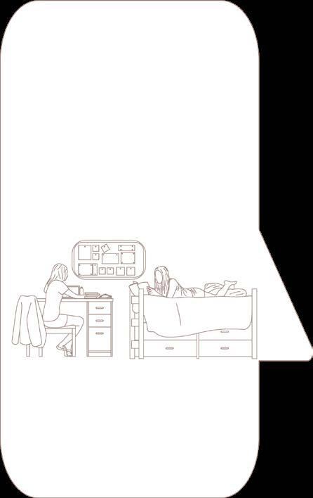

Live-work modules are locted in all three units. Currently, Unit 1 has the highest ratio.It is an adaptable space where commu nity members can chhose room functionalities in accordance to their comfort.
MARKET SPACE FOR COMMUNITY GATHERINGS
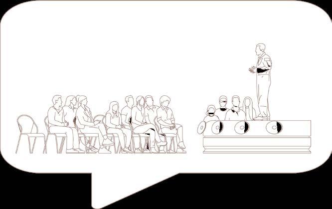

Marketspace is a community focal point where communi ty members get to present their ideas to their neighbours, Witney residents and visitors. This is a good opportunity for testing the ideas and gaining client market.
OPEN AND SEMI-COVERED SOCIALISING AREAS
The site is equipped with numerous locations for socialisation in public, semi-private and private settings. This helps to sus tain the balance between living and working.
SITE PLAN GROUND LEVEL (1 : 500)
1 2 3 4 2 2 3 4
BUILDING ELEVATIONS
Building elevations show

a) the materials used for the exterior: horisontal timber rainscreens on live-work modules, and ashlar brick clad ding on the work-socialise modules to match the local buildings look,
b) maximum building height of 5 storeys shown; however due to the adjustable nature of the building structure the building height can be adjusted based on the local area policies and the demand of CoI,


c) only some trees are on the elevation, this is to hvae a better overview on the proposed building, the south facade has more trees that have been preserved during construction; the rees provide shading on the site and to the ground levels,
 North Elevation. Unit 3 & 2 (Left to Right).
200
East Elevation. Unit 1, 3 & 2 (Left to Right). 1: 200
West Elevation. Unit 2, 3 & 1 (Left to Right).
200
South Elevation. Unit 1 & 3 (Left to Right).
1:
1:
1: 200
Service vehicle access (bin collection, delivering building parts and goods)
Private vehicle access
Due to the availability of parking on the nearby street and in attempt to reduce car use the car spaces on the site are limited; good infrastructure encourages the latter too. supporting local objectives of reducing the traffic in town centre and church green area by introducing entry points on the other side
Pedestrian and bicycle routes. Site visitors can walk freely through the ground levels of Unit 1 and Unit 3. Unit 2 has semi-public right of access therefore the passage through the ground level is restricted to certain hours.
On-site parking for residentsP
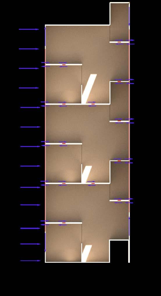
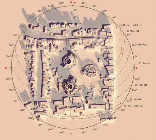
The supath diagram show the shadows from the buildings, with lighter coloured shadow being December and darker June. The South side of the site gets the most sunlight through out the year, therefore the windows on this and East side have passive solar shading that is explored on the next page. The positioning of the windows is so that the residents get the most daylight and the best views.
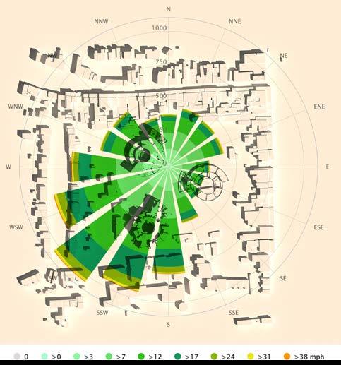
The blue arrow represent prevailant wind di rection on the site. Due to the open nature of the ground levels of the units, The buildings do not abstruct site ventilation.


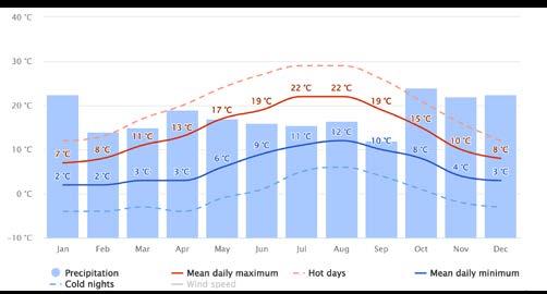
The “mean daily maximum” (solid red line) shows the maximum temperature of an aver age day for every month for Witney. Likewise, “mean daily minimum” (solid blue line) shows the average minimum temperature. Hot days and cold nights (dashed red and blue lines) show the average of the hottest day and cold est night of each month of the last 30 years. The site does not have a big temperature am plitude, which means the difference between highest and lowest temperatures is not ex treme.
The precipitation rate on site is highest in Janu ary and October with the maximum of 90mm. The average in the UK for these months is ranging between 83-90mm. The lowest precip itation rate in Witney is in February and Sep tember, about 56mm. The average in the UK for these months ranging between 65mm.
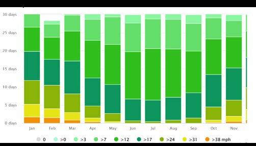
The wind rose for Witney shows how many hours per year the wind blows from the indi cated direction.
P P
1 : 500
UNIT 1 UNIT 2 UNIT 3 WIND SPEED AVERAGE TEMPERATURES & PRECIPITATION WIND ROSE
The top levels of the building get a lot of direct sunshine throughout the day. Exterior shading panels are installed on the East, South and West facades of each unit to stop them from overheating.
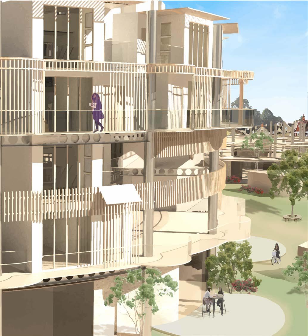
Ground levels have an opposite issue with having a lot of shade from the surrounding. For that reason ground levels are equipped with large windows to increase the amount of natural light the space gets. Live work units are positioned in the wy that the large windows face outwards. This is to get the maximum natural light in the appartents and the best possible views.
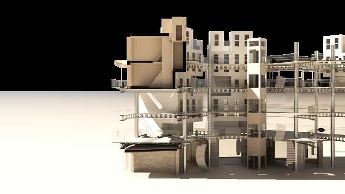 South facade of Unit 1. Shading Pnels.
The building uses passive solar design where the thermal mass absorbs the heat that gets slowly released in the evening. The building has plenty of natural ventilation due to the structural openings. Each unit is located in the way to ensure the air can pass through the site without getting obstructed.
SUN SHADING STRATEGY
1
MEGASTRUCTURE
UNIT
OPTIONS
This sectional view on the units shows that by using the base struvture (megastructure) and 2 types of modules, the space can be adjusted to different needs of the community of innovators. Including demand for different size idea development and production space.


1:200


UNIT 1
PRIVATE LIV ING AND WORK FROM HOME MODULES WORK AND SO CIALISE SEMI PRI VATE AND PUBLIC MODULES


SINGLE
DEVELOPMENT
500
UNIT 2 UNIT 3
came across this precedent later on in my design stages, far beyond the point of creating the spaces and their render. The caption for the precedent captures so well what the design of the Community of Inno vations strives to be.
1. SOME OF THE APPARTMENT WINDOWS FACE INWARDS INTO THE “COURTYARD“
2. EXPOSED GANGWAYS
3. TRANSPARENT LIFTS
4. PLANTS INSIDE
THE CAPTION:
“Here, you can walk on gangways suspended from the treetops, talk to your neighbors about the toma toes ripening in the communal garden on the roof, and watch the Bruz landscape while sheltered from the weather.

Here, natural light is everywhere, even in the car park, and vegetation is present on every floor, even on the roof.
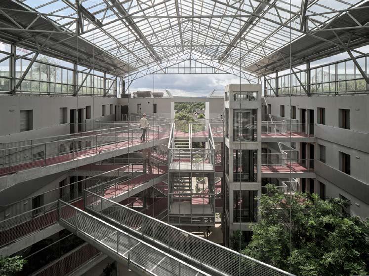
In the flats, residents always benefit from a double ex posure providing sunshine and nice views, and a large balcony protected by white glazing. On the roof, you can enjoy winter and summer gardens, which light up at night like lanterns to liven up the town’s skyline”
ROOFTOP SOCIALISATION/ COMMUNITY GARDEN SPACES
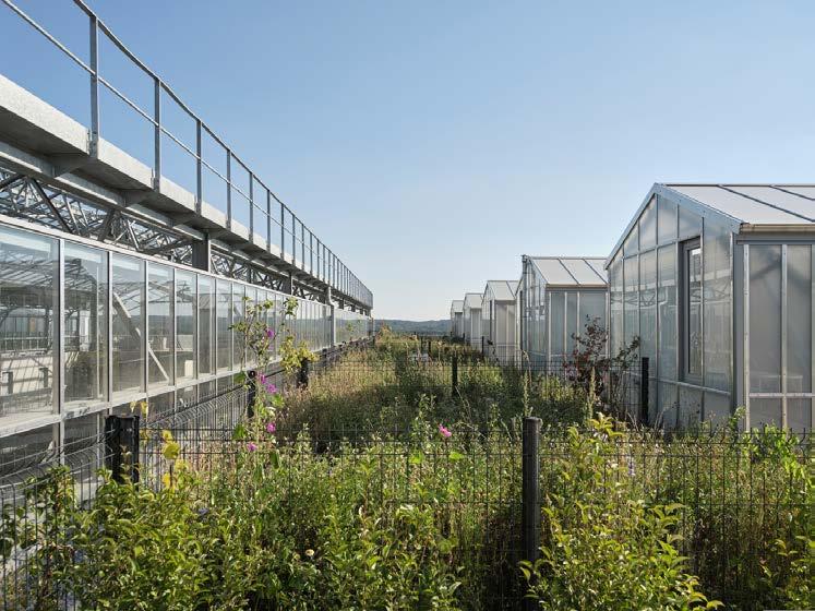
DESIGN PRECEDENT: BRUZ UTOPIA HOUSING CHAMPENOIS ARCHITECTS
THE DEVELOPMENT
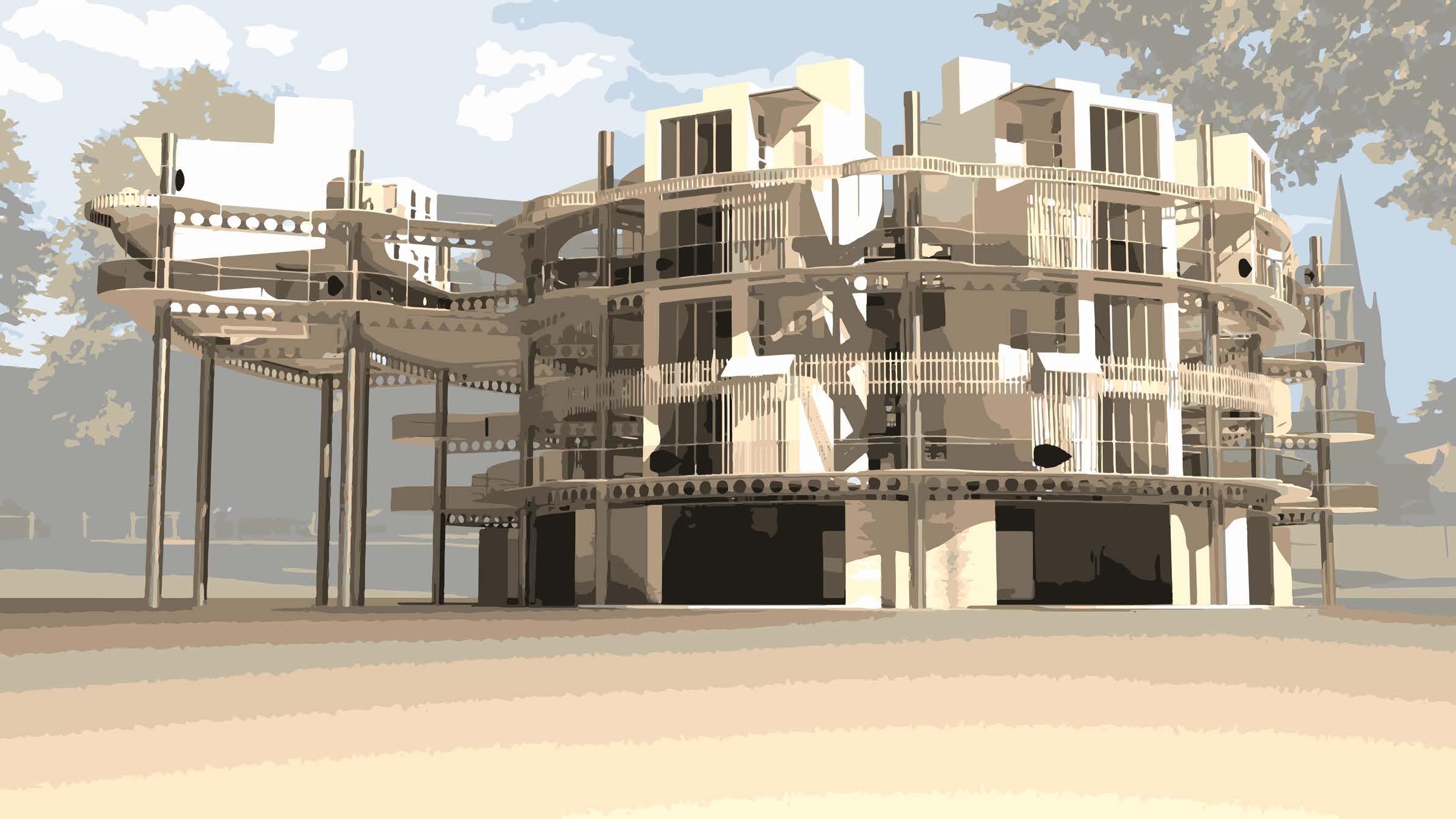
UNIT #1 ON THE COVER: UNIT 1 WEST FACADE
LIVING SPACES GARDENING UNITS


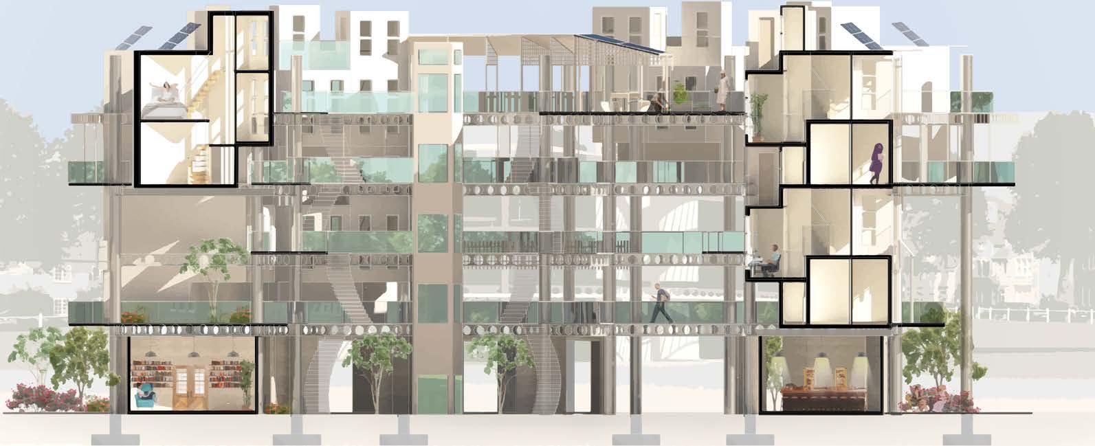 LIVING SPACES
UNIT #1 CO-WORKING SPACES CAFE
COURTYARD GROUND LEVEL LEVEL 1 LEVEL 2 ROOFTOP LEVEL 3
GROUND LEVEL
TOTAL № OF MODULES: 7 (WORK/SOCIALISE)

Ground Level (GL) of unit 1 is mostly open pub lic access. In accordance to the current devel opment plan, the spaces on the GL are work, leisure and socialisation. The assigned room functionality can be changed with changing demands of CoI.
The spaces are made as open as possible to a) get enough daylight, and most importantly to b) make the unit more welcoming for visitors and community members. This was done by providing a through walking path that is open at any point of day and night, cafes, sitting areas and a library with outdoor sitting area. The latter 3 are located on the SE side of the unit close to the main site footpath to increase the visibility. On the NW side of the GL are semi-private working spaces where community members and regestered visitors can co-work and hire spaces for business.
The toilets are of public access.
The level is monitored by security that are lo cated on the NW side of the building.
Walking area

Mechanical rooms
Semi-private spaces
Public spaces
Main entrance points
Building administra tion/security room
Co-working spaces
Co-working spaces
Gender neutral WC Cafe
Computer space Library Courtyard
Playground
1 2 3 4 9 8 5 6 7 1 2 3 4 5 6 7 8 9
Ground Level courtyard of Unit 1 is designed as a public/semi-public space where people co-work and socialise. Non of the enclosured spaces are private, but some of them will only be accessible for residents of the community or specialised staff members.
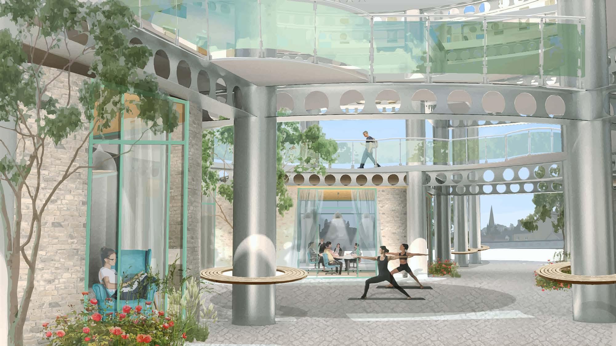
The view is the entrance to Unit 1 from the SouthWest side. People are free to walk through the courtyard to the other side of the site.
This view too shows the exposed structural ele ments of the megastructure including composite beams and round steel columns.
The walkways on the next level have glass balus ters supporting the feeling of the openess provid ed by a pass through the building.
*The view is aimed at conveying the atmosphere of the courtyard therefore some spaces in the col lage have different function to the same places on the actual plan.
Areas that are touched by the view
View catchment
Direction of the view

 Courtyard of Unit 1 showcasing building structure and social “pockets“.
UNIT #1: COURTYARD
TOTAL № OF MODULES: 4 (LIVE-WORK)

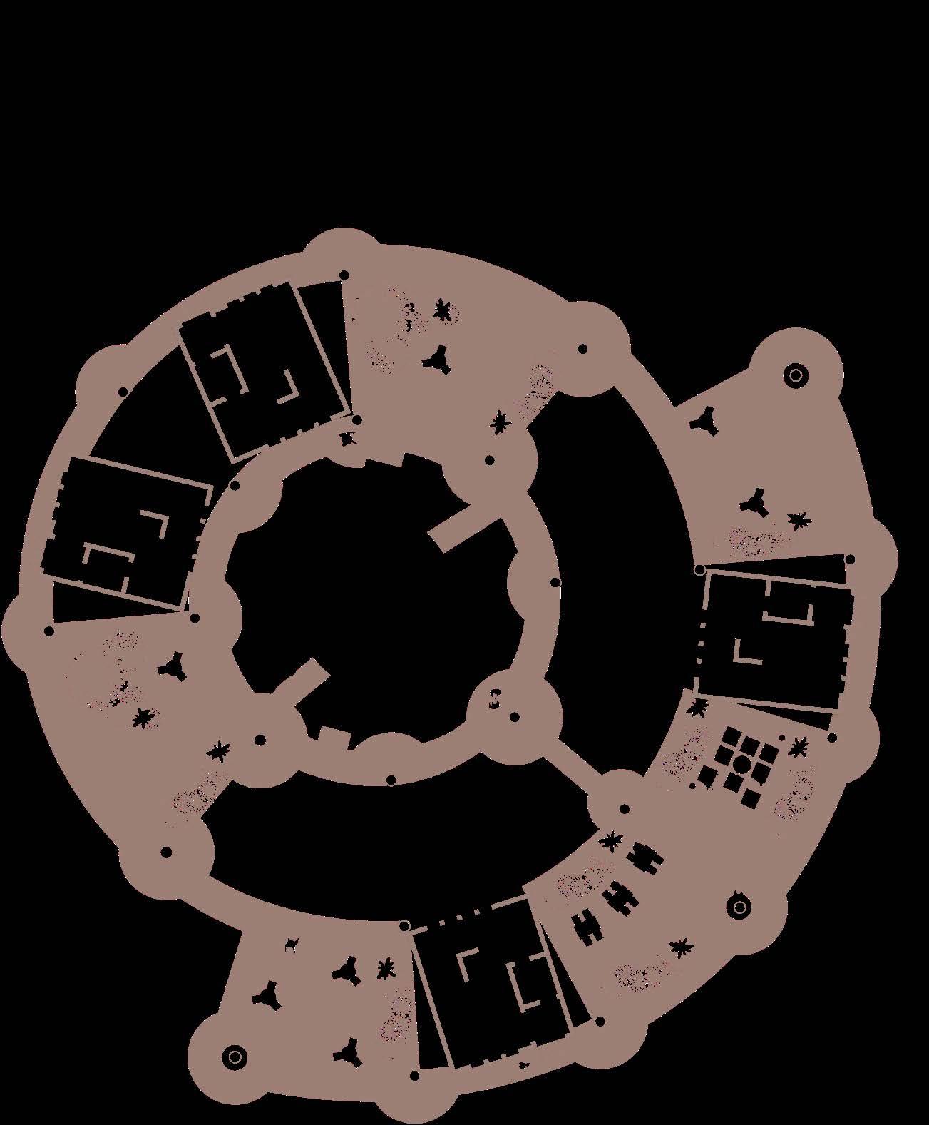
Level one is mostly public access. Here, the res idents and visitors of the community can enjoy semi-covered outdoor spots with a view on the surrounding areas.
Here, first live-work modules are introduced.
Having a semi-covered outdoor areas near the residential facilities is important for providing live-work balance and guard people against po tential social isolation of working-from-home.
The modules’ entrances and latge windows face outwards to provide the residents with the best possible view and the daylight.
Walking area
Private spaces
Public spaces
Main entrance points
Live-work modules
1 1
2 2
Semi-covered work ing/socialising areas
LEVEL ONE 1 1 1
2 2 2
2
TWO

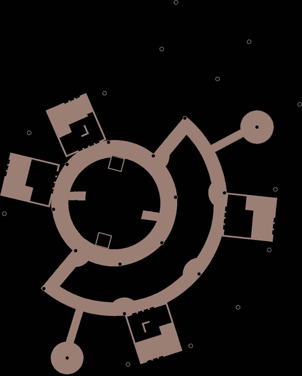
Level 2 is a transition zone between more public to more private areas on the top of the building.
Walking area
Semi-private spaces
Main entrance points
Live-work modules1 1
LEVEL 1 1 1
TOTAL № OF MODULES: 9 (LIVE-WORK)
Level 3 is another transition zone. Unlike level 2, it isn’t open for general public. The measures to control privacy can include pastcode/card ID that should be used on the staircase and in the elevator to get to this level. In the event of fire, the locked private doors will automatically open. In case the system doesnt wor, emergen cy key can be used.
Level 3 has walkways and slightly wider areas tht can be used as a semi-enclosed spaces for leasure/work/socialising
Walking area
Private spaces
Semi-private spaces
Main entrance points
Live-work modules
Semi-covered work ing/socialising areas
1
LEVEL THREE 1 2 1

2 2 2
1 1 1 1
1
1 1

ROOFTOP
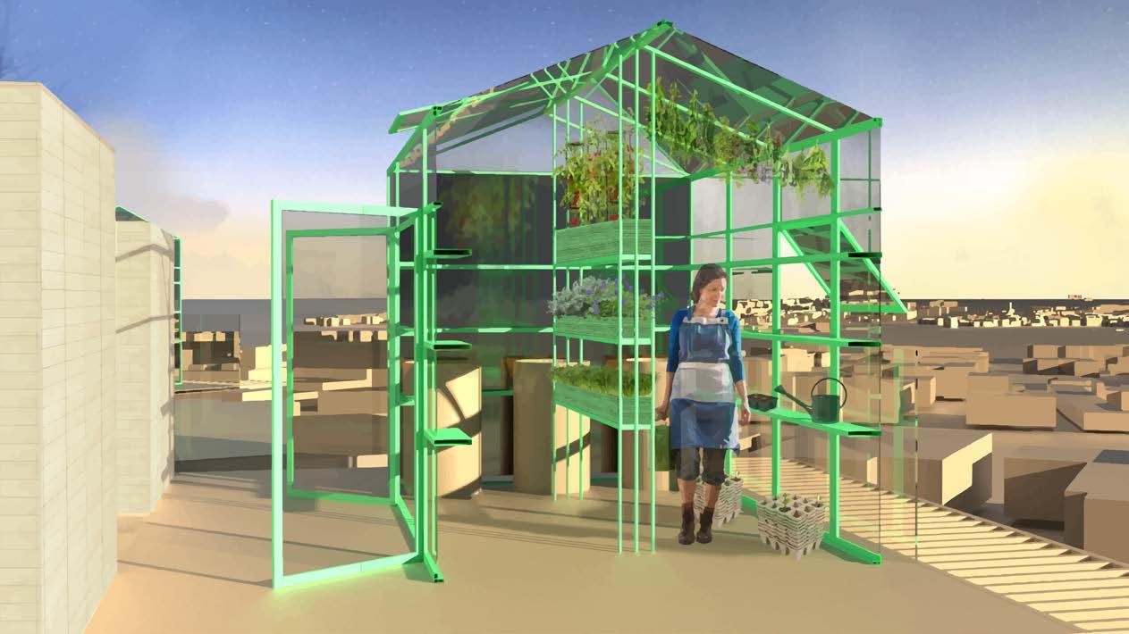
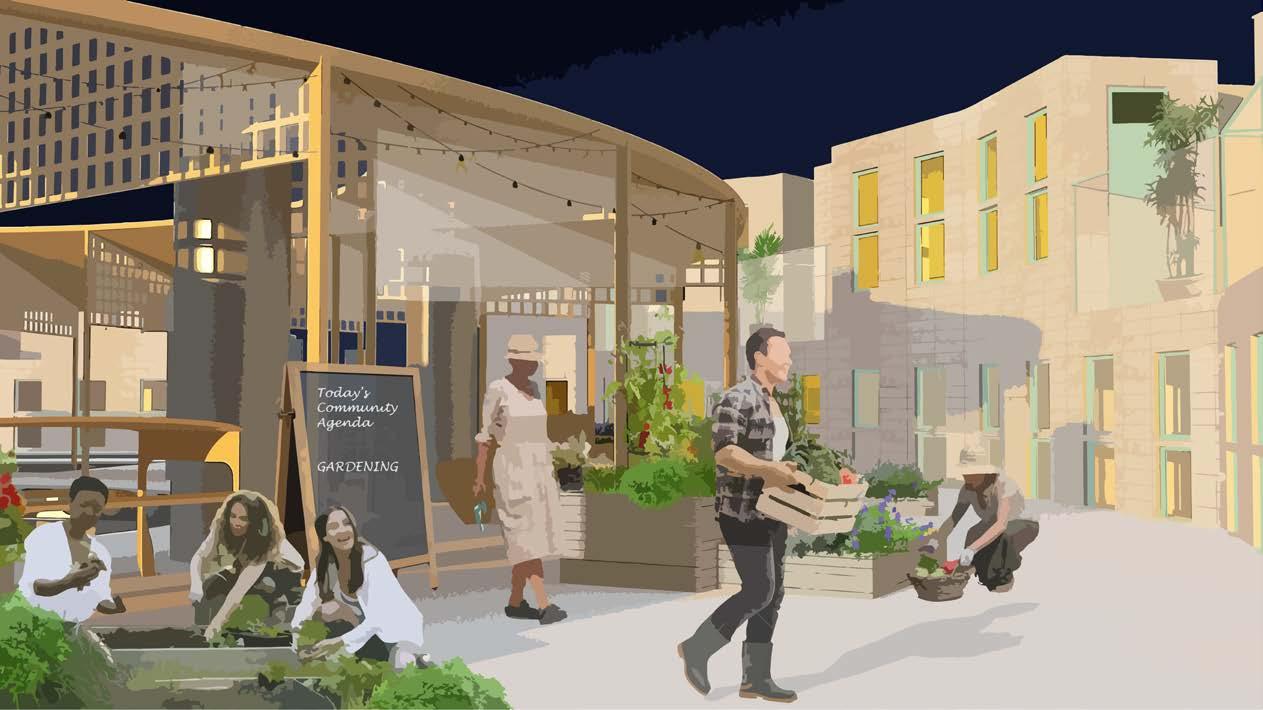
The rooftop is an important community space. By providing terraces and shared gardening spaces & communal stairs/corridors CoI intro duces opportunties for the residents to meet their neighbours. The rooftop gives people a quality living environment that helps develop community feeling.
There is a potential for additional greenhouse space on top of module roofs. It can be used during winter time and heated through thermal mass.
The balcones on the modules positioned so that the neighbours can still communicate from one house to another.
Walking area
Potential areas for greenhouses
Balconies
Private spaces

Semi-private spaces
Main entrance points
Live-work modules


1


Gardening & commu nity gathering areas
Good visibility
1 2 1 1
2
1 2
1 2

1 1 1

1
Rooftop is a place for community occa sions. It is a space for welcoming new community members, celebrating success of members who are leaving, having com munity commity and establishing weekly agenda. It is what the precedent is de scribed as “...talk to your neighbors about the tomatoes ripening in the communal garden on the roof, and watch the Winey landscape while sheltered from the weath er. On the roof, you can enjoy winter and summer gardens, which light up at night like lanterns to liven up the town’s skyline”

Areas that are touched by the view
View
Areas that are touched by the view

View
 Image 1: Farewell. It is a summer evening with. Cool breeze is in the air, the garden lights and a setting sun light up the rooftop. Community came together to celebrate one of its members. Her idea is ready to go out to the the world.
Image 2: Community garden. is the end of a working week and time to get the mind of daily worries.
Image 3: Wintertime. Here is what a greenhouse can be. That’s what they call a greenhouse with a view. you look closely into the light blue sky, you will see the snowlakes dancing valse. Good morning world!
UNIT #1: ROOFTOP (EXAMPLE OF SOCIAL STRATEGY)
catchment Direction of the view
catchment Direction of the view
Here is the external view on Unit 1 and Unit 2 be hind it. The collage imaging what the site could be if it was an alternatife steam-punk future.
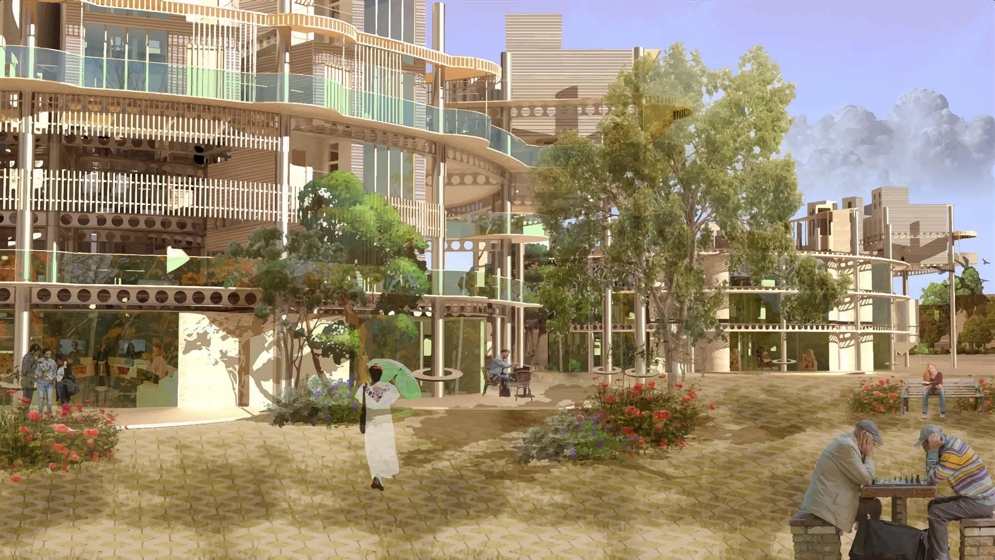
OUTSIDE VIEW: IMAGINARIUM
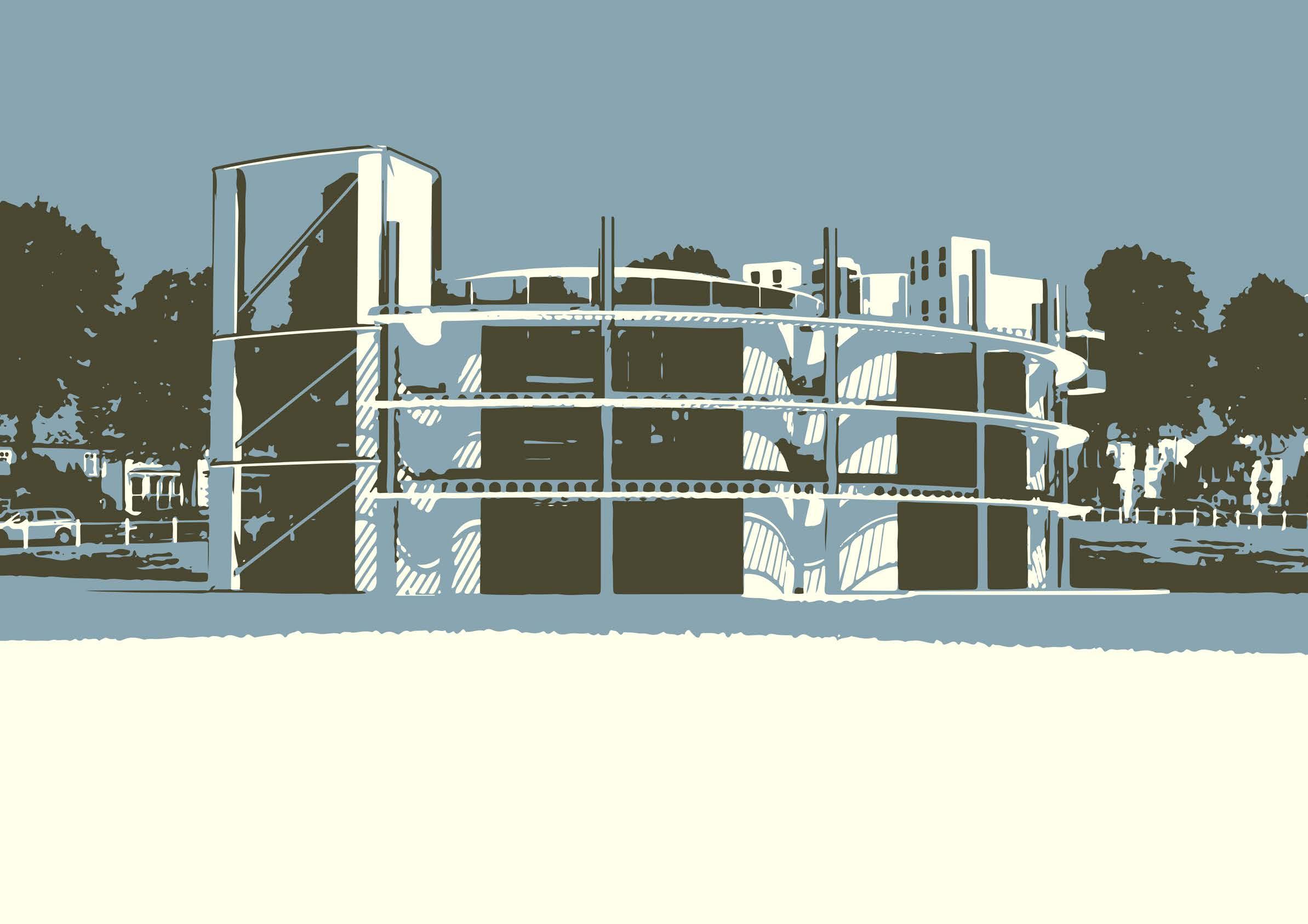
UNIT #2 ON THE COVER: UNIT 2 SOUTH FACADE
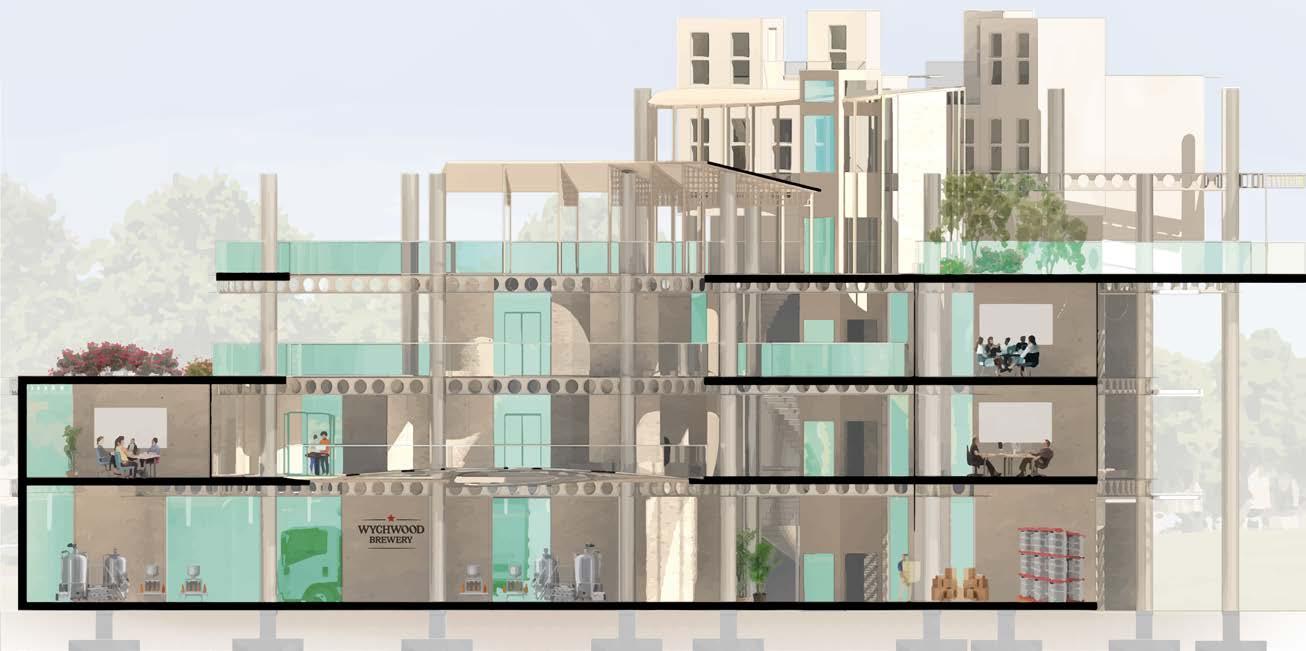


 LIVING
UNIT #2 CO-WORKING SPACES GROUND LEVEL LEVEL 1 LEVEL 2 ROOFTOP CO-WORKING SPACES
SPACESLIVING SPACES ROOFTOP SPACE
GROUND LEVEL
TOTAL № OF MODULES: 3 (WORK/SOCIALISE)
Ground Level (GL) of unit 2 shows how larger business can be arranaged and operated in CoI. Here, the company gets to sell & promote their product in the shop & bar. The offices and staff area are located on the next levels.
Visitors of unit 2 can move through the GL with staff permission. They get to observe beer mak ing in action through semi-transparent partition wall.
Walking area
Mechanical rooms

Supervised public path Public spaces
Semi-private spaces
Main entrance points
Private Spaces
Building storage/ equipment room
Brewery
Brewery shop Cafe/bar
Gender neutral WC
Employee entrance Loading/unloading bay Lobby Brewery equipment
1 1 2 3 4 5 6
1 2

6 7 7 8 9 8 9 9 5
TOTAL № OF MODULES: 7 (WORK/SOCIALISE)
Level 1 is for members of CoI. The office spac es can be let for presentations and business events.
The space between the work-socialise modules is available for the co-workers for leisure and work.
Walking area

Mechanical rooms
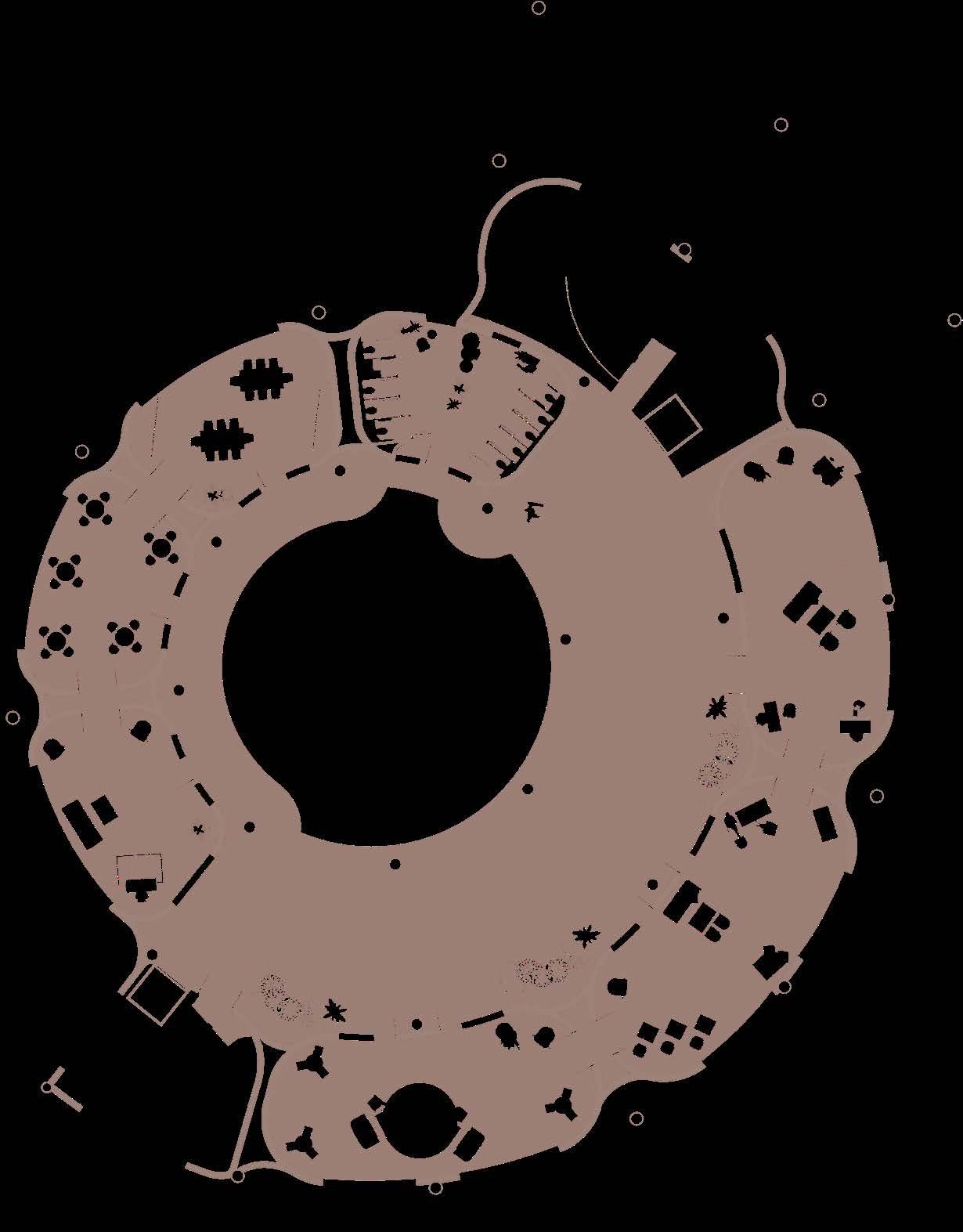
Semi-private spaces
Main entrance points
Private Spaces
Building administra tion
Office space
Co-working/break rooms
LEVEL ONE 1 2 2
Gender neutral WC 2
Semi-covered areas
1
3 3 3 3 4 4 4 5 5
TOTAL № OF MODULES: 7 (WORK/SOCIALISE)
Level 2 has the same layout and functionality as level 1. These are ony suggested numbers of working spaces. That can be changed by adjusting building structure according to site demand.
Walking area
Mechanical rooms
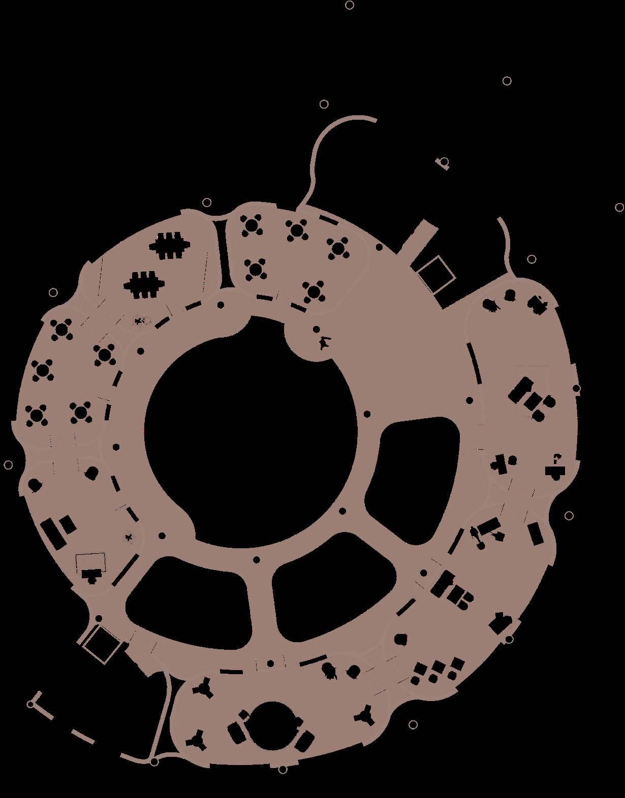
Semi-private spaces
Main entrance points
Private Spaces
2

Office space
LEVEL TWO Building administra tion1 1
2 3 3
2 2
Co-working/break rooms
3
3
Areas that are touched by the view
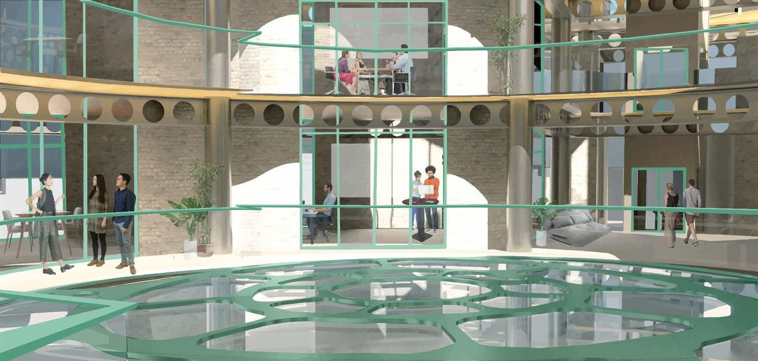
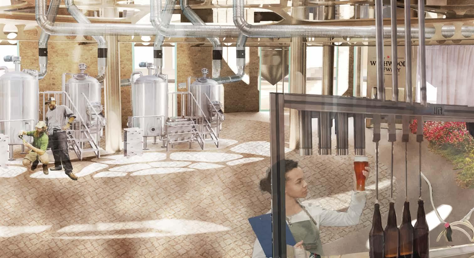
View
Direction of the

 GL of Unit 2. A day in life of the local brewery.
L1 of Unit 2. Working environment.
INSIDE THE BUILDING
catchment
view
TOTAL № OF MODULES: 2 (LIVE-WORK) + 6 (WORK/SOCIALISE)
ROOFTOP Office space
Walking area
Potential gardening units
Semi-private spaces
Main entrance points
Private Spaces Co-working/break rooms
Building administra tion1 2 3 4
Live-work units
The rooftop of unit 2 has a similar structure to unit 1. The space is intended for the users of the businesses and people living in this unit. 1
2
2


4 4 3 3 3
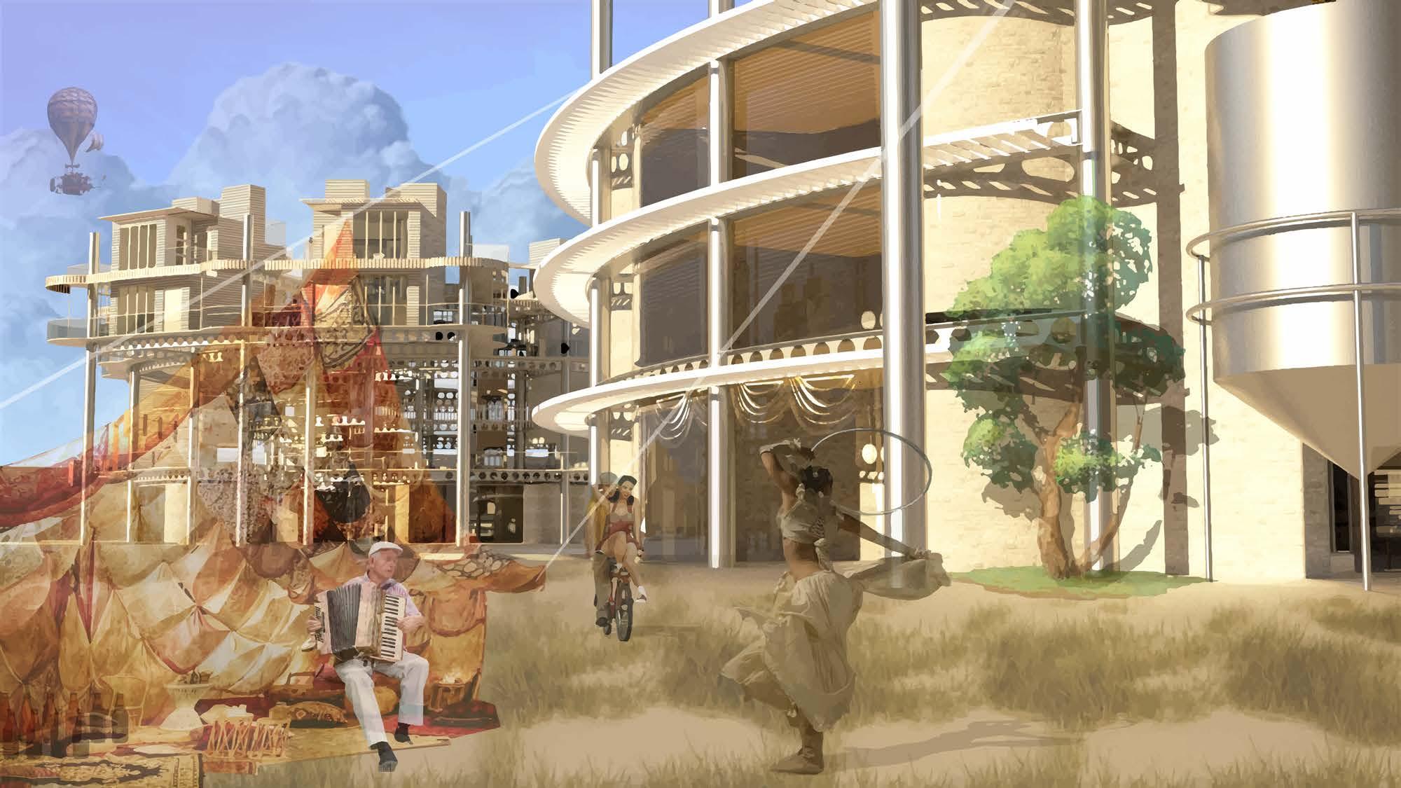 Community picnic for people in CoI and the visitors.
COMMUNITY DAY
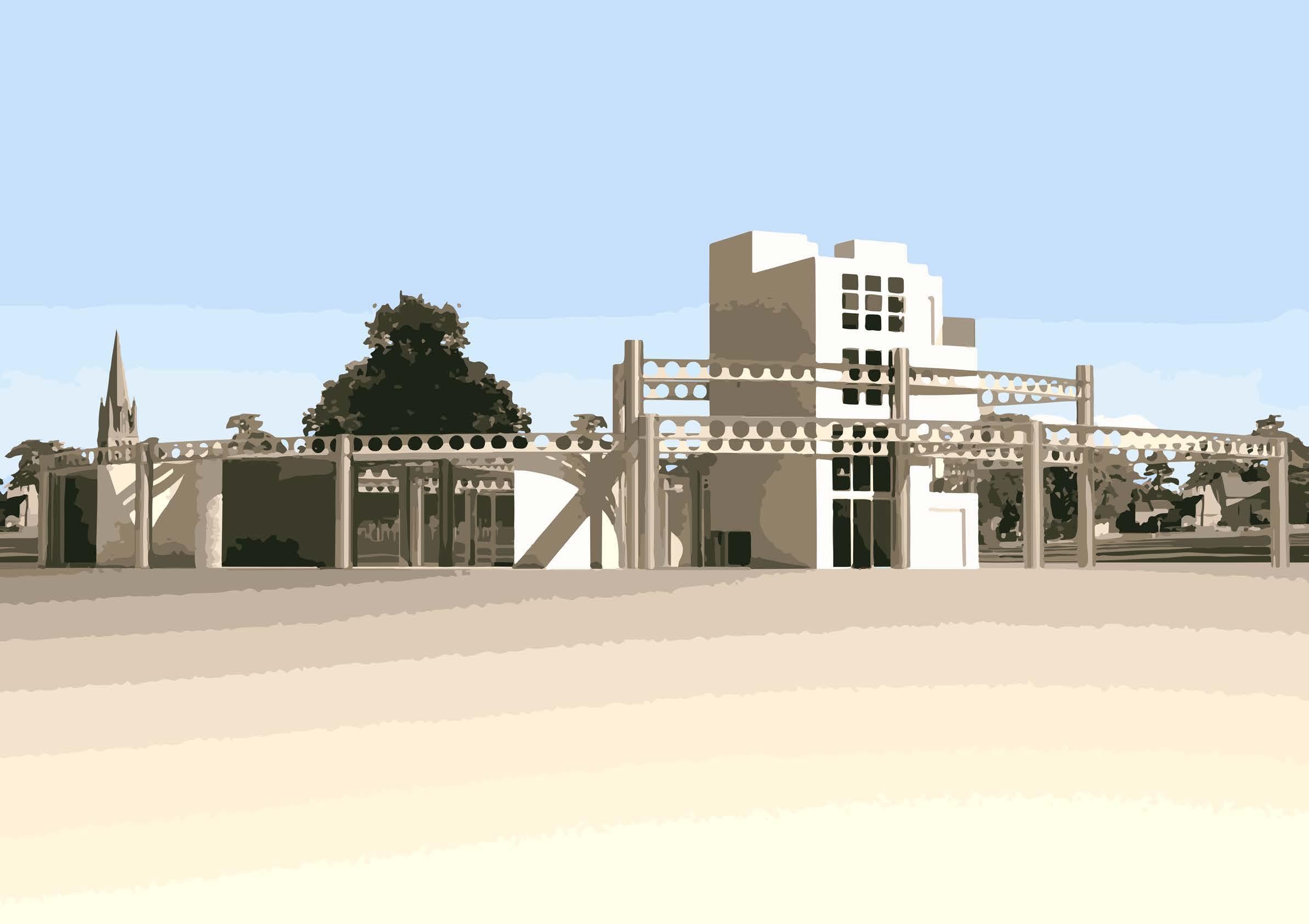
UNIT #3 ON THE COVER: UNIT 3 NORTH FACADE
LIVING SPACES

CAFE

MARKETSPACE FOR THE COMMUNITY RESIDENTS TO PRES ENT THEIR IDEAS


COURTYARD MARKETSPACE FOR THE COMMUNITY RESIDENTS TO PRES ENT THEIR IDEAS

UNIT #3
TOTAL № OF MODULES: 2 (LIVE-WORK) + 6 (WORK/SOCIALISE)
Ground area of unit 3 is the community focal point where CoI members and Witney resi dents get to come together. There, the innova tors present their ideas and products.
People get to have an area for sunbathing, playing chess, and other leisure activities.
On the floor plan, you can see an example of live-work module where the dwellers establish their business from home.
One of the most important examples of the development, is the South side of the ground level where the pre-existing businesses on the site moved temporarily to while the other parts of the CoI were developped.
MARKET
1
Walking area

Mechanical rooms
Semi-private spaces
Public spaces
Main entrance points
Display/leisure rooms
GROUND LEVEL - COMMUNITY OF INNOVATIONS 2
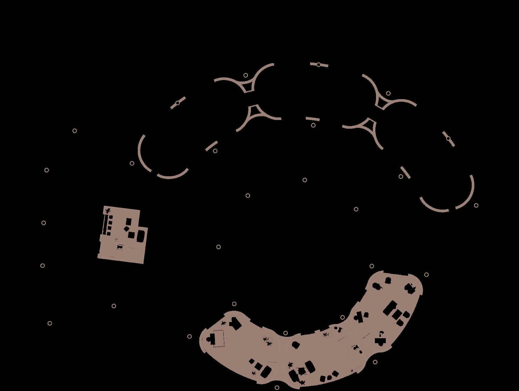
Live-work unit
Courtyard
Pre-existing businesses
1 1 1
2 3 3 4 4 4 4
VUC production benefits from making recycled steel with materials harvested from demolition. The containers have about 26% less GHG impact compared to baseline steel systems, mainly due to being manufactured entirely of steel, 100% of which can be recy cled.
One of the main features of a VUC is that it can be dissassembled and re-used at the end-of-life stage, which is 25 years (Wallance, 2021).


RE-USE
RECOVERY
The lightweight of the VUC container comes from its structure being made entirely of steel. VUC light weight can reduce the materials used in supporting structures and foundtions.
CO2 NOISE

RE-USE RECYCLERECOVERY
The primary steel structural members are bolted to each other, making construction an easier process. The parts can be dissassembled and re-used at a different point of a building or recycled and used for VUC construction.
Steel is a very common construction material, therefore it is easily fabricated in different sizes and shapes to bear specific loads in a building.


Steel structure is lighter and stronger than weight bearing concrete or wood.

VUC (Volumetric Unit of Construction) design is still a new concept, but there is a path towards operating globally. Standardised VUC (container) design will bring about sub stantial cost reduction in urban housing.

The lightweight of the VUC, which is about one-third the weight of a traditional steel frame building with precast concrete floor, allows to transport the containers with less GHG emissions output. With the global sustainable development goals truck fuel stand ards are expected to yield further CO2 reductions of 30-45% over the period from 20102027 (Wllance, 2021).

AIR POLLUTION reduction
VUC prefabrication and the fact that it comes with rainscreens pre-attached, means that fewer trucks trips are required in the process of delivery to the site.
Prefabrication reduces duration of on-site construction, the waste on site (with fewer dumpsters and roll-onn roll-off pickups); fewer emissions and noise pollution during con struction process; less trffic congestions, tailpipe emissions, sidewalks and streetspace needed.
Steel has high fire resistance which can be increased with flare retardant coating.


Good weather and pest resistant properties of steel make it a good material to be ex posed to the outside factors. Hot zinc coating and extra powder treatment make it more immune to rusting.

BUILDING MATERIAL SUSTAINABILITY AND LIFECYCLE
CRADLE-TO-CRADLE LIFECYCLE ECONOMY OF SCALES ADAPTABLE STRENGTH & DURABILITY FIRE RESISTANCE OUTSIDE FACTORS RESISTANCE TRANSPORTATION PREFABRICATION
RECYCLE
CRADLE-TO-CRADLE LIFECYCLE
This page looks at the sources for main construction material - steel.


There are two major locations for types of manufacturing that this project uses. One is for prefabricat ed containers, the other is for primary structure steel parts.
There is a number of container providers around Witney. For exmple, Oxford Containers Company. They sell and modify containers. This company can be hired to customsie the containers for the site in Witney.
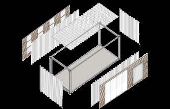
Each live-work module contains 5 separate containers in 3 different sizes. with the current develop ment plan initially the site needs 17 modules, which makes it 85 containers in total. Or 43 trucks to deliver the containers on site. The distance is about 14.6 miles. 10,802,309,576.96 CO2 grams per truck one way. It is a large amount of CO2 emissions. Hhowever CO2 emissions are significantly lower on site and during manufacturing process due to use of prefab building parts, and reused materials for manufacturing the containers.
If the global sustainable development goals are reached , truck fuel standards are expected to yield fur ther CO2 reductions.
The steel for the primary structure will be delivered from area near Swansea, Port Talbot Steel Factory. Winey is about 122 miles away from Port Talbot. It is worth considering using railway system for delivering steel components to the nearest train station and then transporting them to the site by lorry.

This might be a more optimal solution for shipping the containers too. Rail is about 3 times more fuel efficient than trucking.
ON-SITE CONSTRUCTION PROCESSS (WHERE DO LORRIES AND CRANES GO)
The main access points for cranes and services are in pink. The purple access is extra access tht can be used when the development reaches its maximum permitted scale. The site surface is grasscrete. This is to minimise the damage to the site during construction. It has high load bearing capacity, has opti mum drainage capability, while still providing greenery and reducing the ambient heat.
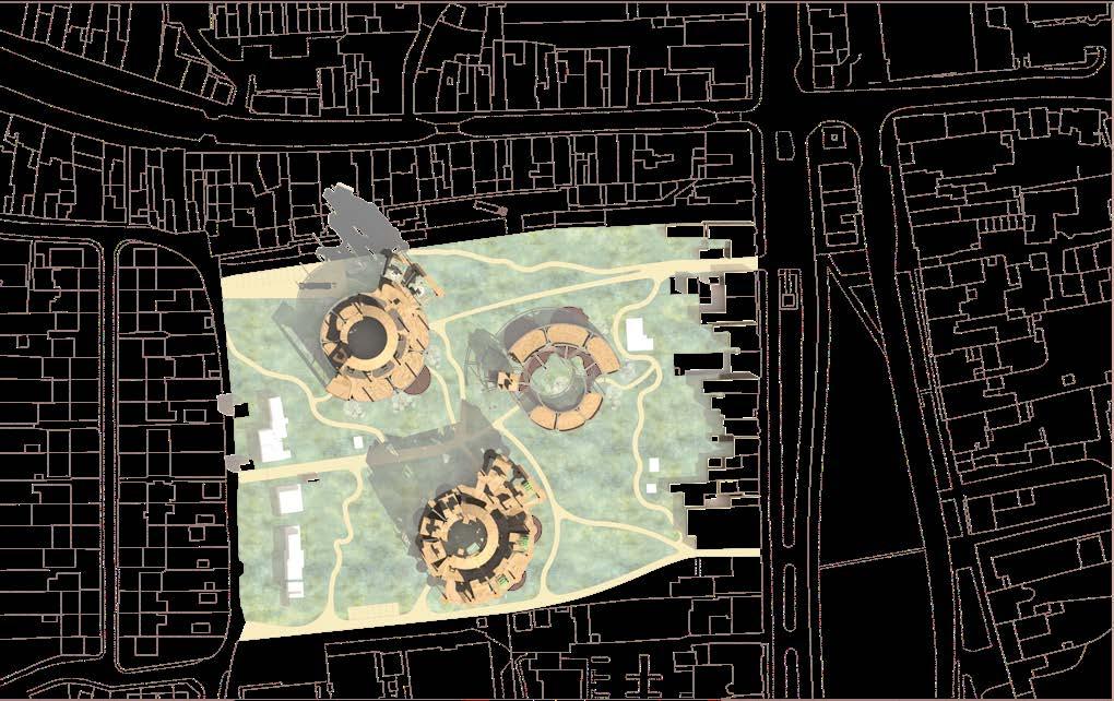
CONTAINER AND BUILDING PARTS MANUFACTURING AND TRANSPORTATION
Servicing of the CoI (Community of Innovations) runs through building columns. Being 600 mm in diameter, the columns fit in electrical cabeling and piping.
ELECTRICITY
Each top level is equipped with a solar panel which feeds elec tricity into the houses. The community accommodates up to 100 people at the moment. Excluding work environment, this is around 909 kWh per person per month. The solar panels are re sponsible for production of 250kWh per month, which is 27.5% of the total demand. The rest 72.5% are used from the power grid.
No combustable fuels are used to service the building. Electrici ty is a safer and easier to maintain.
RAINWATER STRATEGY
Roofs are euipped with rainwater drainage and collection sys tem. Downpipes run from the roof to the rainwater collection tank. It then gets filtered and goes to the main tank where it is stored. From there, filtered water is pumped to the smaller water tank and to the rest of the building. Harvested rainwater saves 10% - 40% of water consumption per house (depends on how many houses area stacked on top of each other).
HEAT STRATEGY
Air -to-air heat pupmps are used to heat up the air and water. The air is drown from the outside, compressed and distribut ed to the hydrobox. The hydrobox transfers heat to the central heating system. The air source heat pump heats up the hot wa ter cylinder and the water then gets distributed to the radiators, showers, tabs, etc. Each house needs a 5kW air heat pump.
SAND
RAIN WATER WATER TANK
INVERTER ELECTRIC PANEL METER
THE HYDROBOX AIR SOURCE HEAT PUMP
Building services shown in 1:50 section. As the building consists of the same parts, the servicing system applies throughout.
MAIN
Each VUC facilitates the interconnection of prefabricated building services. Prefabricated VUC systems are more precise than field-constructed steel or concrete frames. Pre-manu factured “cassettes“ containing a bundle of rises reliably posi tioned so that when VUCs are stacked, each pipe and duct will be alligned with the pipes and the ductes above and below. Cassettes can be prefabricated to fit in chase walls, kitchen ceilings, etc. Cassettes contain multiple trades - plumbing, HVAC, sprinklers, and even lighting - are sourced from special ty manufacturers as supply chain components, sheduled to arrive at the assembly plant ready for rapid installation. At the building site, quick-connect devices are used to join piping and ductwork across mate-lines (Wallance, 2021).
Example of BIM model of mechanical, plumbing, and fire sprinkler systems in VUCs (Wallance, 2021)
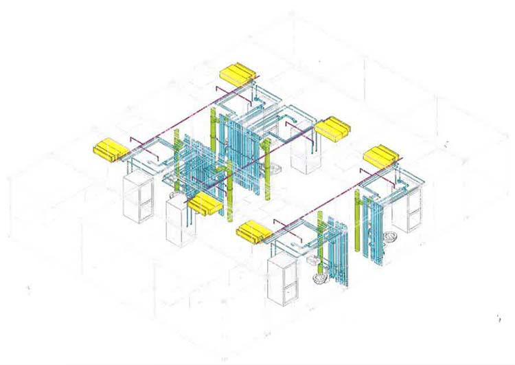
VUC (LIVE-WORK MODULE) SERVICES SERVICES
FILTER
TANK PUMP COLUMN SECTION COLUMN SECTION
OUTDOOR UNIT SOLAR PANEL RAINWATER DRAIN
CONSTRUCTION
This page explores systems that can be used in live-work modules.
MODULES
INTERMODAL MODULAR SYSTEMS
Lightweight steel structure presents acoustic and vibration challenges. The floor needs to be stiff enough to provide low “deflection“; the flow needs to have low number of mips (“micro-vibrations per second“); damping should be factored in, by adding layer of cork or rubber un derneath a wood or tile floor, damping can reduce the vibration ener gy transmitted by footsteps.
Containers that form a module are mostly open-sided to protect in terior materials and finishes during transportation, modular reusable protection panels are installed prior to shipping. After removal at the job site, those panel are sent back to the factory for re-use.
INTEGRATED PARTITIONING AND CABLING
Stressed-skin honeycomb core panels are used for threading cables for the circuits. After that, wood veneer is glued to a core. Apartments are circuited by cable harnesses theat run overhead raceways.
The partitioning can be used in live-work modules wish the residents to adjust the interior.

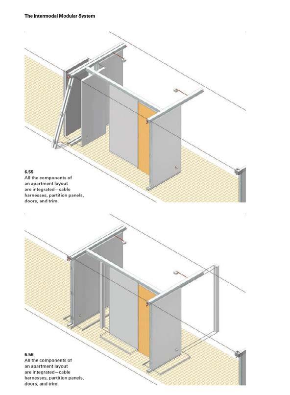
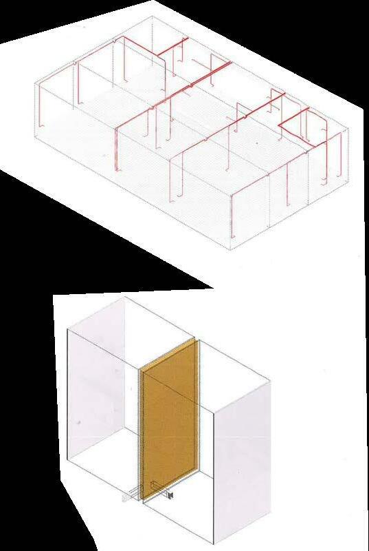
Partition panels are attached to a snap-fit framing system tht includes an overhead wireway, a baseboard receptor, and light-gauge posts to support the edges of partitions, spaced up to 4 feet apart.
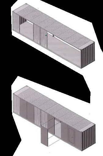
unprotected VUC openings.
Cable harnesses run in over head raceways. Quick-con nect devices allow circuits to be rapidly complete between VUCs in the field.
Temporary protection pan els.
Honeycomb - core partition panel
FIRE PROTECTION STRATEGY
Two types of fire protection are used: membrane fire protection systems and direct-applied fire protection. Membrane systems comprise a fire-resistant wrapper that encloses hollow constructions such as joist-sup ported floor, or stud walls. Direct-applied fire protection comprises a fire resistant material.
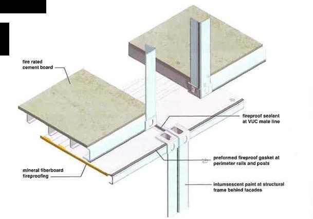
Intumescente fireproofing, a thin coating, is used at the perimeter of VUCs to facilitate the attachment of facades.
Panelized membrane fire proofing at interiors of VUCs.
CONSIDERATIONS FOR LIVE-WORK
*From Wallance, 2021
This page shows evacuation strategy from each level on every unit. The emergency exits will be equipped with signs. Non emergncy exits get locked automatically in the event of fire and sprinklers are activat ed. The site assembly points are located on site car parks.


UNIT 1


Emergency Exits Evacuation di rection lines
MODULE
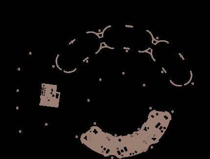



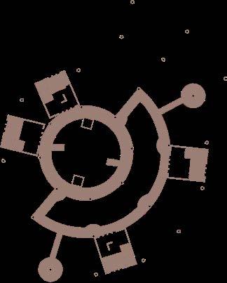


UNIT 2
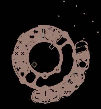
UNIT 3 LIVE-WORK
FIRE STRATEGY EVACUATION PLAN GL 1L GL 2L ROOF TOP 1L 2L 3L ROOF TOP
APPENDICES
In live-work communities people and places are important.
Communities need collective purpose and values to thrive.
People within the live-work communities need live-work balance to thrive. This is created through spaces for socialisation, private life and work life. These spaces need to provide the correct level of privacy.
Places themselves need adequate relation to the surrounding commu nities and adaptability capability to thrive.
CONCEPT: STATEMENT GO
SUSTAINABLE COMMUNITY LIVING GUIDE
1. Living as a unified body of individuals while adjusting, transforming and evolving in face of challenges with consideration for traditions, present situations and future changes,
2. Where consumers and producers are not geographically and/or psychologically distant from each other and not being anonymous. This helps to value the labour and prevent exploitation of natural and social capital
CONCEPT: LIFE-WORK BALANCE
RESILIENT / ADAPTABE
Communities and spaces that "learn" from their environments and evolve with them.
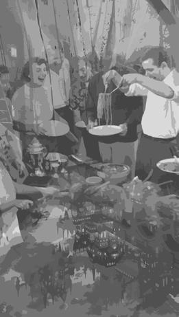
CONCEPT: SEPARATION OF LAYERS, METABO LISM
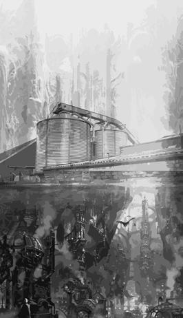
RELATABLE
Personable spaces based on current social needs and with respect to local culture and traditions.
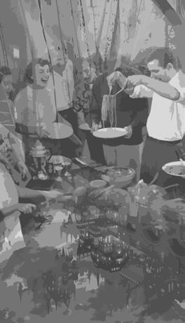
Memberss should be able to connect with the spaces they inhabit through materiality, light and scale.
CONCEPT: SEPARATION OF LAYERS, LIFE BE TWEEN BUILDINGS


UNIFYING
Mixed use spaces that encourage social inter actions and different types of activities.
Where life between the buildings as important as life within them.
CONCEPT: LIFE BETWEEN BUILDINGS
BIOPHILIC
Spaces that connect inhabitants with nature, use sustainable local materials, and encourage appreciation for natural resources.
SUSTAINABLE COMMUNITY LIVING
(
TO) ( GO TO) ( GO TO) ( GO TO)
Retreat is a place to bring people together.
The retreat is a space to commemorate the members of Oxford Brookes community, give them an anonymous platform to share thoughts, feelings and memories

Existing metal plaques on Oxford Brookes territory as a way to remember the presence of community members.
Examples of ‘Mirrors of Civilisation’



Medieval tapestry depicting events (left) and graffity in a night club (right) have similar function but in a more publically-controlled and available man ner. Both exist to commemorate events and people.
Retreat is designed to guide a visitor by sound and light. On their journey, people will be able to express their thoughts on the walls of the building.
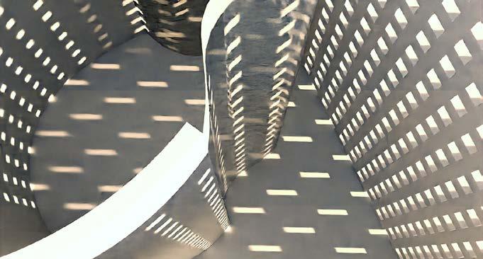
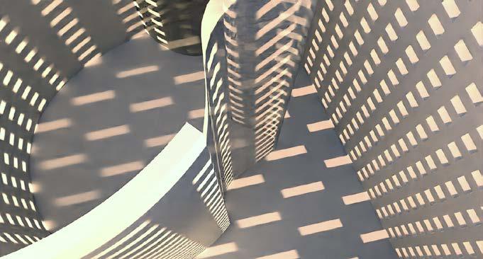
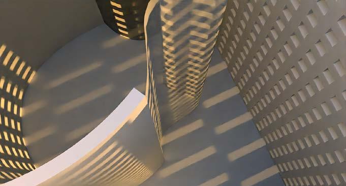
 GUIDING BY LIGHT (TOP, RIGHT). RHINO MODEL + PHOTOSHOP COLLAGE.
C
B
A (V-Ray for Rhino)
SEMESTER 1RETREAT: EXPLORATORY STUDY SUSTAINABLE COMMUNITY LIVING 3D PRINTED PROTOTYPE OF SPACE ABOVE (GUIDING BY LIGHT -SPACE IN RED). RIGHT (RED) SPACES OF RENDERS ON PICTURES A, B, C.
RETREAT PROTOTYPE
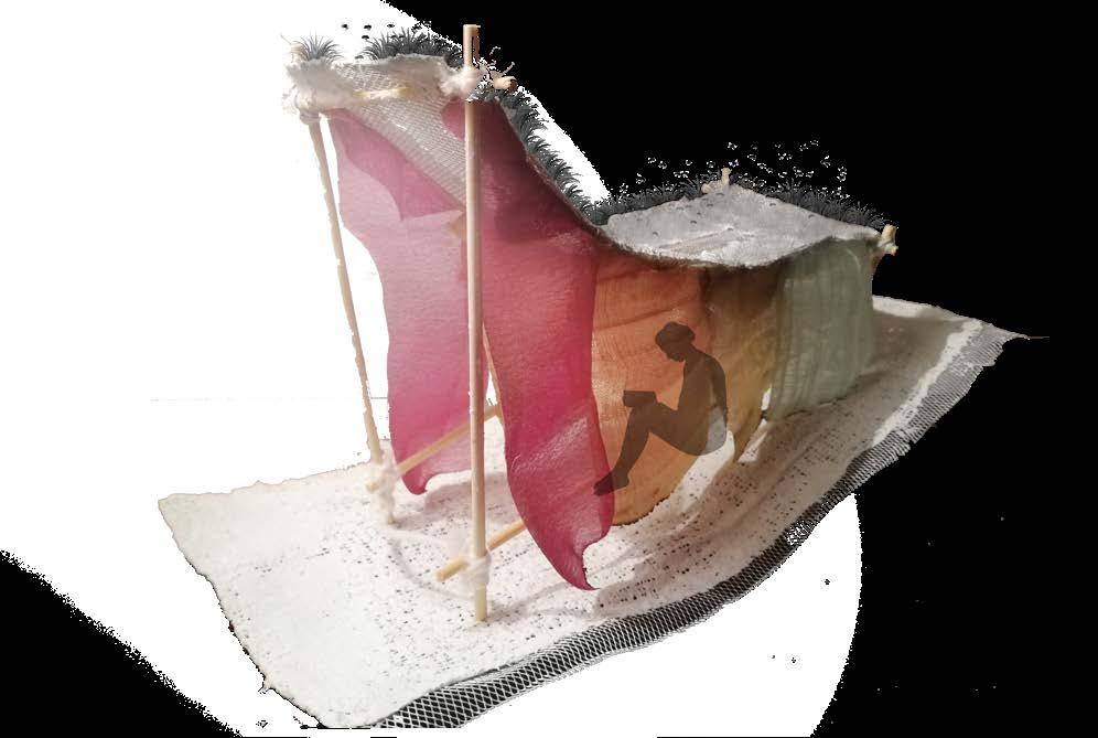
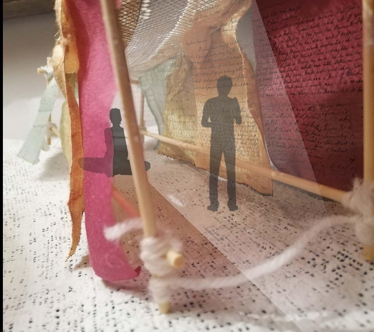
Space for students and members of staff to breath, pause, enjoysound, silence, air, light, nature
The retreat helps visitors to recognise the value of the place by emerging them into the surrounding atmos phere.
SOUND/SILENCE AIR LIGHT
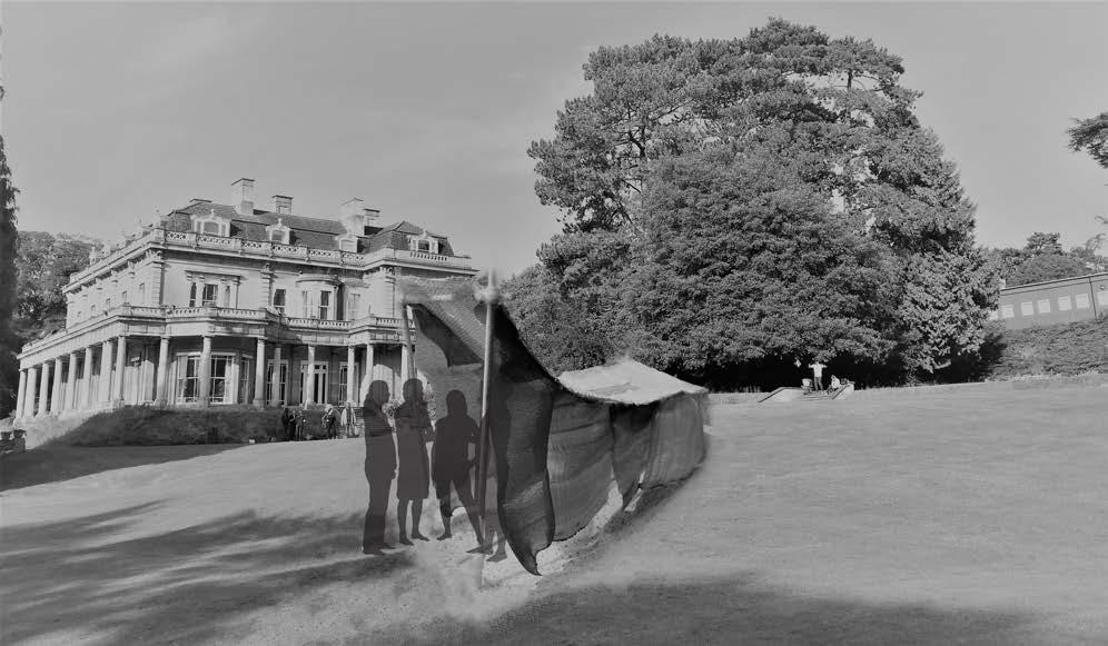
These are 3 different room sizes inside the retreat that receive the surrounding sound electronically and amplify it by having curved walls.
Sound is aimed to create awareness of surroundings and make the visitors feel more present. This is another way of commemorting the events at Oxford Brookes University.
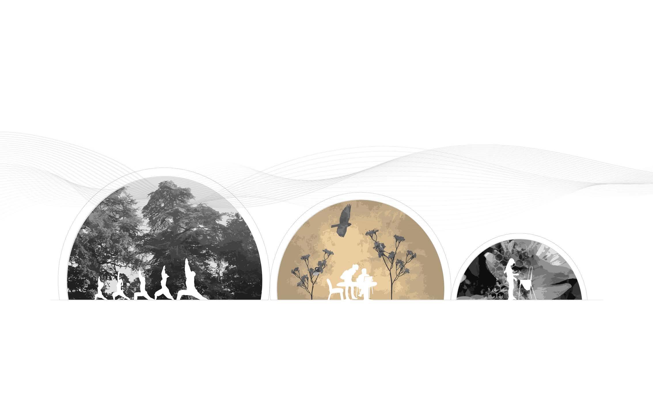
GUIDING BY SOUND
The main view.


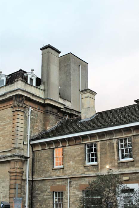



 Flow through the retreat
Different size rooms for different size groups.
Materials to reflect existing historical buildings.
Green roof to protect existing flora and fauna.
Collage of the Retreat. Rhino, Adobe Illustrator and Photoshop.
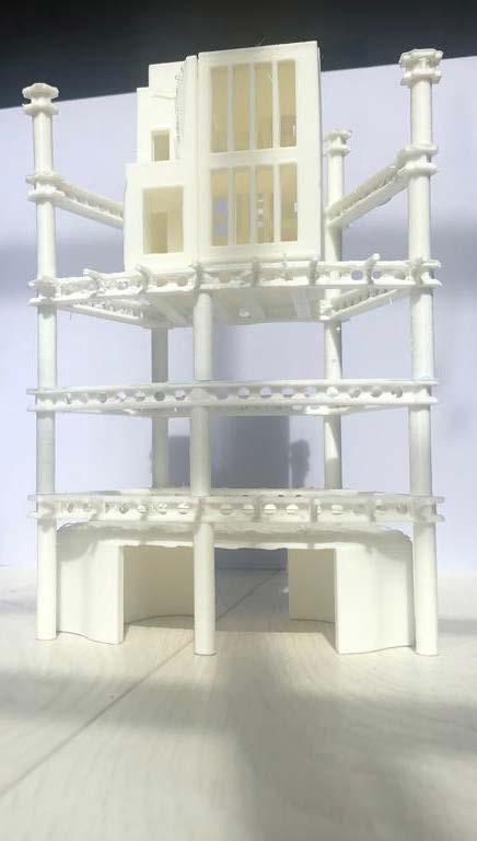
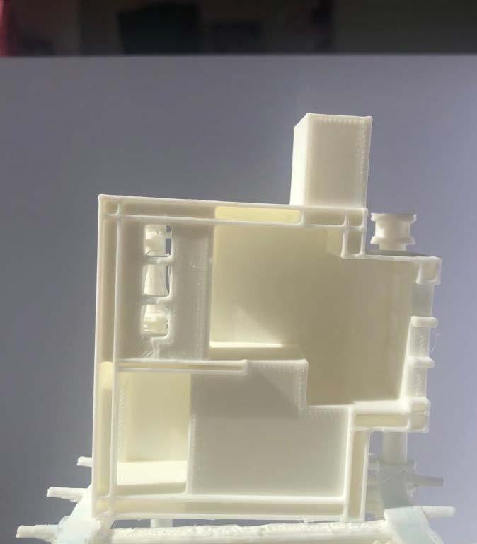
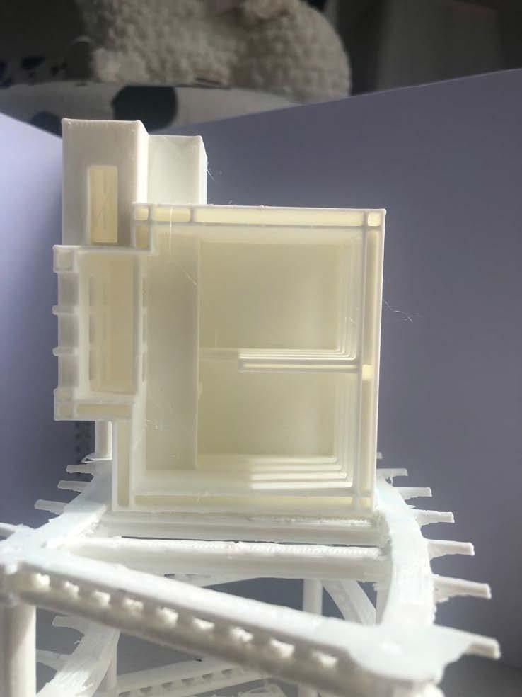 3D PRINTED SEGMENT OF THE BUILDING SHOWING PRIMARY STRUCTURE (BEAMS AND COLUMNS) AND MODULES.
PHYSICAL MODEL FOR COI (SUSTAINABLE COMMUNITY LIVING)
BIBLIOGRAPHY
p. THE PLACE AND THE NAME
Local Insight profile for ‘Witney’ area, LI - Oxfordshire Community Foundation, Report created 22 June 2020, https://3p50ut4bws5s2uzhmycc4t21-wpengine.netdna-ssl.com/wp-content/uploads/2020/08/Local-Insight-Full-Report-Witney-Parliamentary-Constituency.pdf
https://planningconsultation.westoxon.gov.uk/gf2.ti/-/193986/612909.jpg/jpg/-/Witney%20Town%20Centre%20Map.jpg
Core Strategy Preferred Approach February 2010 https://planningconsultation.westoxon.gov.uk/CSPreferredApproach/viewCompoundDoc?docid=365108&sessionid=&voteid=&partId=366004
https://www.oxfordshirecotswolds.org/dbimgs/Travel_WitneyGreen.pdf
Local strategies, strengths and weeknesses: Westoxton, 2020 https://www.westoxon.gov.uk/media/feyjmpen/local-plan.pdf
ADAPTABILITY
Sharp, D. (2005). ‘Kenzo Tange (1913–2005)’, Architectural Review, May, p 36. [Robert Schmidt III, Simon Austin.Adaptable Architecture: Theory and practice]
Lin, Z. (2010). Kenzo Tange and the Metabolist Movement. Oxford: Routledge. [Robert Schmidt III, Simon Austin.Adaptable Architecture: Theory and practice]
Adaptable architecture theory and practice
Schmidt, R. and Austin, S. A. (2016) Adaptable architecture theory and practice. New York: Routledge. Available at: https://doi-org.oxfordbrookes.idm.oclc.org/10.4324/9781315722931 (Accessed: January 27, 2022).
LIFE BETWEEN BUILDINGS
Gehl, J., 1987. Life between buildings (Vol. 23). New York: Van Nostrand Reinhold.
SITE STRATEGY
https://planningconsultation.westoxon.gov.uk/CSPreferredApproach/viewCompoundDoc?docid=365108&sessionid=&voteid=&partId=366004
SUSTAINABLE COMMUNITY LIVING DEFINITION (refer to appendix 1)
Sophie A. Hadfield-Hill (2013) Living in a sustainable community: new spaces, new behaviours?, Local Environment, 18:3, 354-371, DOI: 10.1080/13549839.2012.714760
Mark Roseland,Sustainable community development: integrating environmental, economic, and social objectives, Progress in Planning,Volume 54, Issue 2, 2000, Pages 73-132, ISSN 0305-9006, https://doi.org/10.1016/S0305-9006(00)00003-9.
C.B. Flora, J.L. Flora
Entrepreneurial social infrastructure: a necessary ingredient
Annals of the American Academy of Political and Social Science, 529 (1993), pp. 48-58
J.S. Coleman
Social capital in the creation of human capital
American Journal of Sociology (supplement), 94 (1988), pp. S95-S120
R. Putnam, R. Leonardi, R. Nanetti
Making Democracy Work: Civic Traditions in Modern Italy, Princeton University Press, Princeton, NJ (1993)
Litfin, K.T., 2014. Ecovillages: Lessons for sustainable community. John Wiley & Sons.
En.wikipedia.org. 2021. Permaculture - Wikipedia. [online] Available at: <https://en.wikipedia.org/wiki/Permaculture> [Accessed 19 September 2021].
Holmgren, D., 2011. Permaculture: principles and pathways beyond sustainability Hepburn. Victoria: Holmgren Design Services.
LIVE-WORK
Sassi, P., 2006, Strategies for Sustainable Architecture, Taylor & Francis
PRECEDENTS
Gehl, J., 1987. Life between buildings (Vol. 23). New York: Van Nostrand Reinhold.
Bruz Utopia Housing / Champenois Architectes https://www.archdaily.com/981045/bruz-utopia-housing-champenois-architectes?ad_source=search&ad_medium=projects_tab
STRUCTURE
FOUNDATIONS https://www.designingbuildings.co.uk/wiki/Pad_foundation
LIVE-WORK MODULES STRUCTURE
Wallance, D., 2021, The Future of Modular Architecture, Taylor & Francis
COMMUNITY OF INNOVATIONS
https://eit.europa.eu/our-communities/eit-innovation-communities/success
Lim, M. and Ong, B.Y., 2019. Communities of innovation. International Journal of Innovation Science.
Upham, S.P. (2006), “Communities of innovation: three essays on new knowledge development”, available at: https://repository.upenn.edu/dissertations/AAI3225559 (accessed 6 April 2022). Mattioli, M. (2012), “Communities of innovation”, Northwestern University Law Review, Vol. 106 No. 1, pp. 103-155.
METABOLISM
Elnaggar, M., Quittenbaum, M. 2019, Metabolism in Architecture - Architecture Diet, Accessed https://issuu.com/mahmoud-elnaggar/docs/metabolsim_in_architecture?fbclid=IwAR2g9qVhHLZmthnow0X5eR_zPKZRMiwfnISybcWFdjPVSr3qIkaO2rU6DJ0
https://sabukaru.online/articles/the-promised-tokyo
Steen, E., 2022 https://www.timeout.com/tokyo/news/the-iconic-nakagin-capsule-tower-has-its-issues-still-were-sad-to-see-it-demolished-033022
Block, I, 2021 https://www.dezeen.com/2021/07/16/nakagin-capsule-tower-dismantled-news/ Kurokawa, K., 1977. Metabolism in architecture. London: Studio Vista.
WITNEY CLIMATE DATA
https://www.meteoblue.com/en/weather/historyclimate/climatemodelled/witney_united-kingdom_2633729
COMMUNITY GOALS
https://www.architecture.com/knowledge-and-resources/resources-landing-page/un-sustainable-development-goals-in-practice
https://issuu.com/kadk/docs/aechitecture_guide_un17_vol.2_web_single_pages
PUBLIC EDGES
Alexander, C., 1977. A pattern language: towns, buildings, construction. Oxford university press.


 The people of community are chosen and approved by the commity members. The members’s proposal need to deliver real products and services and have a future development plan.


 Collage: the collage depicts one of current entrances to the site and what can be beyond it. What will the adaptable sustainable communities look like? What is possible? (by me, Y Kaizer)


 Metabolism in Nature
Marine City Model
Nakagin Capsule Tower
Nakagin Capsule Tower, Capsule Structure
Marine City Floor Plan
Nakagin Capsule Tower, Steel Motherboard
Nakagin Capsule Tower, Capsules Attached by Crane


 Pen Sketch/Photoshop Sketch Idea of Megastructure Units (by me, Y Kaizer)
Rhino Representation of Megastructure Units (by me, Y Kaizer)
The sketch idea for the development of community unit uses the plug-in system introduced by Japa nese architects. The “motherboard“ structure will be made of steel and have module attached to it.
technology Photo
by DickJohn
technology Photo is by DickJohnson


 GL Structural Development 1 : 2000 Render of Site With 2050 Development Scenario
Render of Site With 2050 Development Scenario
Site Area Permitted Construction Development Area Development Simulation


 Living and working units possible location within the units


 EAST FACADE


 On the diagram: How Gehl’s idea can be translated into building environment. From left to right. Social connections chain
Stage A. Visualising contact intensity in society. From passers by to close friends. (by me, Y Kaizer) Stage B. Imagining contact intensity in terms of privacy levels in a vertical develop ment (top image). (by me, Y Kaizer)
The Byker Wall, Newcastle upon Tyne, by Ralph Erskine. Showing soft edges
Collage representing the ultimate aim of this project: to create strong bonds between the members of com munity while sharing common interests and goals. (by me, Y Kaizer)


 The Essence of Arrival. On the collage: The crane is a signifier of community growth, celebration of a new member joining. (by me, Y Kaizer)


 Diagoon House section and floor plans. By Hertzberger
Kitchen Dining Area
Office Space
Bedroom
LIVE-WORK MODULES LAYOUT PRECEDENT Transition Zones


 Warm summer day. Studying in the livingroom. A view on the ground level and first mezzanin level
Daydreaming. A view on transition space between GL and 1L
Music lessons. A view on the first level mezzanine


 A B C D E


 North Elevation. Unit 3 & 2 (Left to Right).
200
East Elevation. Unit 1, 3 & 2 (Left to Right). 1: 200
West Elevation. Unit 2, 3 & 1 (Left to Right).
200
South Elevation. Unit 1 & 3 (Left to Right).


 South facade of Unit 1. Shading Pnels.
The building uses passive solar design where the thermal mass absorbs the heat that gets slowly released in the evening. The building has plenty of natural ventilation due to the structural openings. Each unit is located in the way to ensure the air can pass through the site without getting obstructed.


 LIVING SPACES


 Community picnic for people in CoI and the visitors.


 GUIDING BY LIGHT (TOP, RIGHT). RHINO MODEL + PHOTOSHOP COLLAGE.
C
B
A (V-Ray for Rhino)
SEMESTER 1RETREAT: EXPLORATORY STUDY SUSTAINABLE COMMUNITY LIVING 3D PRINTED PROTOTYPE OF SPACE ABOVE (GUIDING BY LIGHT -SPACE IN RED). RIGHT (RED) SPACES OF RENDERS ON PICTURES A, B, C.


 Flow through the retreat
Different size rooms for different size groups.
Materials to reflect existing historical buildings.
Green roof to protect existing flora and fauna.
Collage of the Retreat. Rhino, Adobe Illustrator and Photoshop.


 3D PRINTED SEGMENT OF THE BUILDING SHOWING PRIMARY STRUCTURE (BEAMS AND COLUMNS) AND MODULES.