12 minute read
Highways
GO GREEN WITH COLAS!
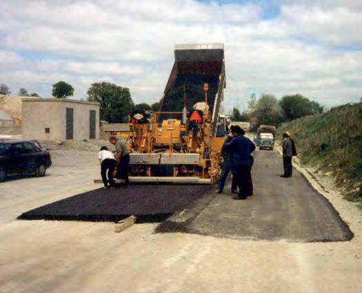
Figure 2: Surface dressing with bitumen emulsion technology is the most environmentally friendly road re-surfacing technique - in addition to being the most cost effective.
Earlier this year, Gearoid Lohan, CEO of Colas Ireland, launched a “Go Green with Colas” initiative to encourage all Colas subsidiaries to play a more pro-active role in meeting their environmental responsibilities. An additional aspect of this initiative is to raise awareness with our many customers and stakeholders of how Colas can help them meet their carbon reducing targets.
Since its establishment over 70 years ago, the Colas Group has led the way in the development of environmentally friendly pavement materials. In fact, the name Colas comes from the words COLdASphalt. Cold-mix asphalt is similar to the more commonly used “hot-mix” asphalt but is producedby using a bitumen emulsion instead of the conventional hot bitumen. As bitumen emulsions can be used with aggregates at ambient temperatures, as opposed to the high temperatures required to manufacture hot-mix asphalt, there are considerable energy and, thereby, carbon savings to be achieved by their use. Colas first introduced the coldmix asphalt technology into Ireland in the 1980’s. In 1990, a cold-mix asphalt called “Graveémulsion” was used inthe base course of a40 km section of the N8 from Dublin to Cork.At that time, the N8 was the highest trafficked road in the country. But the grave-émulsion cold-mix material well and truly survived the test of time. In fact, when it had reached the end of its design life in 2006, there were no signs of distress or failure, with no cracking, an average rut depth of only 3 mm (versus the failure criteria of > 10 mm) and an IRI smoothness indicator of 1.7, which is well below the smoothness criteria for a new road!Since then, Colas Ireland has led the development and promotion of other emulsionbasedmaterials and techniques such as surface dressing, coldasphalt micro-surfacing and in situ pavement recycling. In addition to being a cold-mix technique, in situ cold recycling is one of the most environmentally sustainable and low carbon maintenance techniques that is available to the Local Authority Engineer. As well as being a cold technique, use is also made of the aggregate material already in the pavement. Consequently, there is less use of this valuable resource and there is less or no transporting of aggregates from a quarry or asphalt plant to the jobsite. In addition, the bituminous binder already present in the pavement can also be recycled. Much of these developments have been made possible thanks to Colas Ireland owning and operating its own speciality chemicals company in Oranmore, Co. Galway.Chemoran’s range of emulsifiers and bitumen additives enables Colas subsidiaries
worldwide to design their emulsions and asphalt mixtures to best meet their customers’ needs. Chemoran’s bitumen additive called CWM™ has been used for the production of over 7 million tonnes of warmmix asphalt worldwide and its adhesion agents extend the service-life of hot-mix asphalt by improving the bond between the binder and the aggregate and, hence, its durability. In terms of making a change to reduce the industry’s carbon footprint, switching to warmmix asphalt, instead of hot-mix asphalt, is probably the easiest transition. By simply adding an additive, such as CWM™ into the bitumen, mixing temperatures at the hot-mix plant can be reduced by at least 30oC. Temperature reductions of up to 40oC have been achieved, even with the very dense EME mixtures used in France. Needless to say, the further the reduction in mixing temperatures, the greater the savings in energy use at the asphalt mixing plant and, as a consequence, the greater the reduction in greenhouse gas emissions. It has been widely reported in the literature that energy savings of the order 15 to 20 % can be achieved when the mixing temperatures are reduced by 30 to 40 °C. In Ireland’s case, as we manufacture approximately 3 million tonnes of hot-mix asphalt per year, this would equate to a reduction in carbon emissions of the order 15,000 tonnes of CO2 eq. per annum. In terms of performance, during the past ten years, it has been well established that warm-mix asphalts behave in the same way as conventional hot-mix asphalts. Since 2008, over 7 million tonnes of warm-mix asphalt have been made using the CWM additive alone. Many more millions of tonnes have been produced using other additives. Warmmix asphalt has been used in every bituminous layer of the pavement from base to surface course, including mixes that contain high percentages of RAP, and under all traffic levels. Perhaps as importantly, another significant benefit to reduced mixing temperatures is a reduction in VOCs emitted at the laying site, i.e. less smoke and fumes. It has been established that, as a general rule, for every 12 °C degree drop in mixing temperatures, VOC emissions are reduced by half at the job site. At a trial site in Dublin in 2012, the reduction in VOCs was measured and found to be 80 % lower than that of the conventional hot-mix, when the mixing temperatures were reduced by 35 °C . Another benefit of reduced mixing and laying temperatures is that the pavement will cool to ambient temperatures more quickly and, therefore, can be reopened to traffic sooner. Consequently, there is a less of an inconvenience on the road user. In terms of the costs to implement such a change, the cost of the warm-mix additive will be offset by the savings in fuel use. In addition, if the cost of carbon credits is increased to the € 80 per tonne mark (as is now promised by this government), the net increased cost to the asphalt producer and, consequently to the client, i.e. the Irish taxpayer, will be zero! The road construction/ maintenance industry and the asphalt industry, in particular, has within its grasp the ability to play a significant role in achieving Ireland’s carbon reduction targets by promoting and/or even insisting on the use of both warm-mix and cold-mix asphalt. The benefits are obvious and can be implemented immediately.
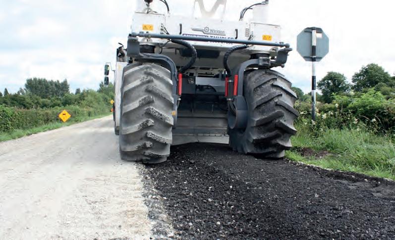
Figure 3: Emulsion bound cold in situ recycling.
For further information on how the Colas Ireland group of companies can help you to reduce your carbon footprint, please contact us at
www.gogreenwithcolas.com
REAL TIME MONITORING SYSTEM PREVENTS MAJOR WALL COLLAPSE IN CO DOWN
The Ballynaclosha retaining wall was constructed in 1999 to enable the development of a fuel service station and ancillaries including buried and aboveground fuel storage to the lower side of the retaining wall. The upper side of the wall retains a section of the Ballynaclosha Road with two dwelling houses approximately 25m from the wall on the retained side. The 47m long cast in situ structure approximately 9m high was connected to the rear rock face via a single row of embedded anchors.
The wall was constructed in eight panels each 6m wide as shown in Figure 1. A condition assessment and site survey identified rotational failure through assumed loss of connection of the rock anchors. This was identified given the extensive movement of the upper section of the wall from the centerline of the wall. The road above the wall was exhibiting large tension cracks and a maximum deflection of approximately 900mm was measured on Panel 4 (Figure 2). The Department for Infrastructure (DfI) commissioned a remedial works program to permanently stabilise the wall through the installation of additional rock anchors. The failure of this retaining wall during remediation works posed significant economic and environmental risks, with potential injury or loss of life to the workers on site identified as the greatest risk. The environmental risk from a potential fuel leak was mitigated through engagement with the fuel station operator and the recommendation that all tanks and fuel storage facilities were to be emptied prior to works. The area to the lower side of the wall was isolated as a no access area within the fall zone of the wall to ensure the safety of users of the fuel station. It was deemed essential by DfI that a rapid response monitoring system be put in place to act as an early warning of collapse and ensure the safety of workers in work zone to the rear of the wall. The system was developed in collaboration with Queens University Belfast (QUB). Monitoring Requirements: A number of traditional retaining wall monitoring systems were considered including automatic total stations and wireless inclinometers, both systems met the accuracy and power requirements on site and minimum access to the wall was needed for installation and setup. A system of wireless inclinometers was designed to measure rotational movement at the upper side of the wall and provide communication to an alarm system, which would trigger in the event of the wall moving beyond a set threshold. The system could continuously monitor 24 hours a day but had a 2-minute latency between data transmission and alarm detection. Given the condition of the wall and risk of instantaneous collapse, this system was deemed substandard to ensure the safety of the workers on site. To remove the latency a wired system was designed however, limitations in mobile data meant this system could not provide remote monitoring and required manual observation of the data output on site. Monitoring system: The final monitoring system was designed using Fibre Optic Sensors (FOS) based on Fibre Bragg Grating (FBG) technology and consisted of: Concrete surface strain: Four FBG strain gauges were attached to measure change in concrete strain on the lower side of the wall on panels 4-6 (fuel station side). An assumption was made that the wall was continuous from top to bottom therefore displacement at the top would result in a change in strain as the lower section of the wall compressed under rotation of the upper section. Wall Displacement: Movement of panel 6 on the upper side of the wall was measured using a micron optics os5500 displacement gauge. The sensor allows for measurement of displacement between two fixed points with an accuracy of
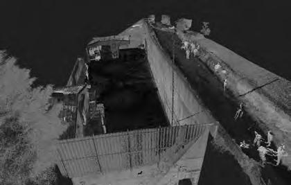
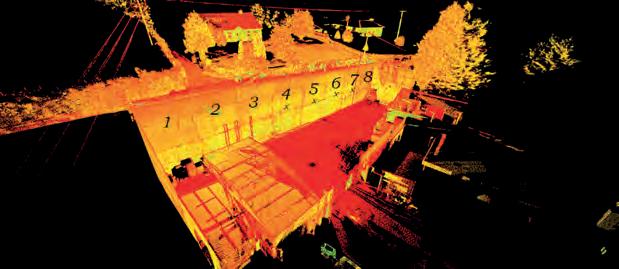
Figure 1 Aerial images of site will numbering of Panels 1-8.
Figure 2 (a) Tension cracks in Ballynaclosha road (b) noticeable displacement from lower side of wall. Figure 3 (A) inclinometers (I1-2) and displacement gauge D1 (b) strain to lower side of wall.

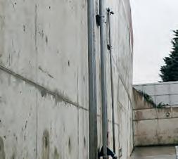
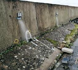
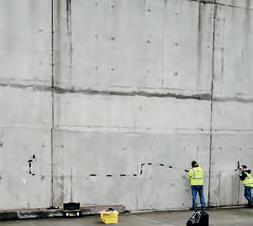
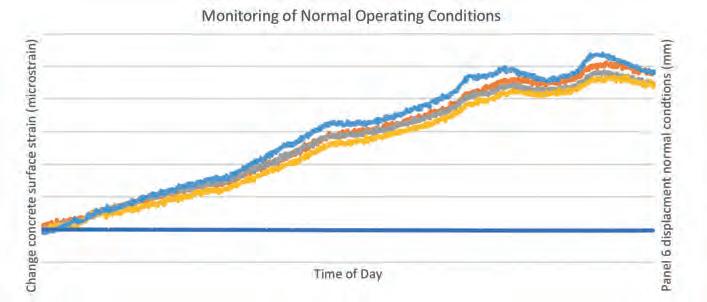
Figure 4 Monitoring data under normal conditions to correlate change in concrete surface strain to displacement.
Figure 7 Inclinometers to measure upper rotation of Panels 1-3 during removal of backfill.
0.03mm. The sensor was bolted to the road surface and a connection wire was fixed to the face of the wall to provide measurement of differential movement. A shown in Figure 3, the requirement for a fixed mounting point only permitted this sensor to operate as validation for the strain sensors prior to works commencing. It had to be removed from the road surface to allow for excavation during works. Wall Rotation: Rotation of panels 5 and 6 was measured using Somi TI 1-ax 500 T Tilt Sensors, the sensor has a total measuring range of 10 degrees and is capable of measuring small angle changes of 0.002 Degrees. The sensors were fixed in place using bespoke mounting brackets and remained in place during the complete works programme. This wired system enabled real time processing of 1000 Hz at each discrete measurement point on the wall and real time processing of the data to capture movement of the wall either through rotation/ displacement on the upper rear side (Fig 3A) or change in concrete surface strain on the lower face of the wall (Fig 3B). A micron optics SM130 dynamic interrogator was used for data acquisition, this unit outputs sensor wavelength data to an external computer via an Ethernet port. Real time post processing was carried out onsite to convert the change in wavelengths to equivalent change in strain or displacement. A temporary site office was located on the access road to the rear of the wall to provide power and secure location for the monitoring equipment. After installation, the system monitored the normal operating conditions of the wall for two 8hr periods prior to commencing works (Figure4) On establishment on the normal operating limits of the wall, works commenced on the 9th of November 2020 to remove the backfill sections immediately behind panel 7, as shown in Figure 7. The monitoring during the excavation provided assurance that panel 5&6 were not subject to movement beyond the normal range and there was limited change on concrete surface strain on the lower side of panel 6. Work continued on the 10th and 11th of November to clear the area behind the wall in order to establish the true location of the rock face for permanent anchoring and long-term stabilisation of the wall. Monitoring was carried out on each day during works but a lack of mobile data prevented remote monitoring when workers were not present on site. Works finished on site at 3.30pm due to rain on the 11th of November and at approximately 5pm, the wall collapsed as shown in Figure 6. The collapse did not cause any injury since the fall zone of the wall was located at the rear of the wall which was isolated outside working hours. However there was an urgent need to establish the true stability of the remaining sections of the wall and make the surrounding area safe. All sensors were destroyed during the collapse but replacements were ordered immediately and installed on site within 48hours. Due to the condition of the wall access was no longer available to the lower side, as such the rear of panels 1-3 were monitored using three inclinometers to enable the safe removal of the remaining fill and deconstruction of the wall. On the 17th of November, the area was made safe and removal of the back fill commenced. Within 2 hours of minor works, the remaining panels were showing movement of up to 10mm indicating a potential further collapse (Figure 8).The system successfully identified unexpected movements in the wall. This acted as an early warning to cease works on site preventing further collapse which posed a risk to life for 3 workers in the area immediately behind the wall. The wall was then continuously monitored for a 2-week period, and the stability of the wall has been assured enabling the development of a safe demolition plan.
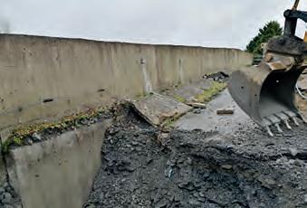
Figure 5 Removal of backfill at Panel 7.
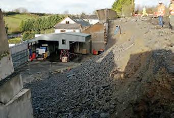
Figure 6 Wall after initial collapse.
