Physics & Engineering
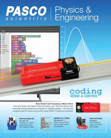
New Smart Cart Accessory: Motor Drive The new Smart Cart Motor Drive Accessory can drive the Smart Cart forwards and backwards at constant or variable speeds – and can be programmed for sense and control using PASCO Capstone software!
Smart Cart Demo Kits See page 104 Everything you need for great physics demos! Demo manual included.
Capstone 2.0 + Coding See pages 68-71 Blockly coding in PASCO Capstone offers limitless lab possibilities!
Sense and Control See page 6 Control hardware outputs with PASCO sensor inputs!
Table of Contents Instrumentation___________________249-257 Power Supplies, Function Generators, & Meters____________________________________249-257
Sensors and Dataloggers____________ 18-67
Waves & Sound____________________258-269
Analog ScienceWorkshop Sensors________________ 18-24 Digital PASPORT Sensors_______________________ 25-45 Interfaces & Dataloggers________________________ 46-48 Wireless Sensors_______________________________ 49-67 Software______________________________________ 68-75 Curriculum and Bundles_________________________ 76-93
Ripple Tank_________________________________258-259 Standing Waves______________________________260-261 Mechanical Waves___________________________262-263 Resonance__________________________________264-265 Transverse Waves/STEM______________________266-267 Wave Media & Tuning Forks___________________268-269
Mechanics_________________________ 94-199
TABLE OF CONTENTS
___________________________________________Page New Products___________________________________ 2-5 Sense & Control_________________________________ 6-9 Interfaces & Dataloggers________________________ 10-17
Light & Optics_____________________270-304
Carts & Tracks________________________________94-125 Freefall & Projectile Launchers__________________126-135 Statics______________________________________136-141 Human Applications__________________________142-143 Structures System____________________________144-157 Materials Testing_____________________________158-164 Hooke’s Law & Springs _______________________165-167 Rotation____________________________________168-180 Fluids, Pipe Network, & Density________________181-185 Lab Supplies________________________________186-199 Rods, Stands, & Clamps______________________186-189 Pulleys, Spring Scales, Measuring, Balls_________190-193 String, Storage, Mass Sets, Stopwatches, Strobes_____________________________________194-199
Basic Optics_________________________________270-275 Polarization & Human Eye_____________________276-281 Diffraction___________________________________282-287 Optics Systems & Components________________288-291 Spectrometers & Interferometers_______________292-303 Microwave Optics________________________________304
Fundamental Constants____________305-316 Atomic & Nuclear__________________317-322 Experiments_______________________323-386 Part Number Index___________________________387-390 Product and Topic Index______________________391-402 Order Information____________________________403-404
Thermodynamics__________________200-211 Thermal Expansion & Conduction_______________200-202 Calorimetry, Gas Laws, & Heat Engines_________203-208 Thermometers & Thermal Radiation_____________209-211
Electromagnetism_________________212-248 Electrostatics________________________________212-215 Circuits & Supplies___________________________216-230 Generators__________________________________231-235 Magnetism__________________________________236-248
PA
SCO
Given the past year’s events, we understand many educators were unable to use their PASCO equipment as frequently as they would during a normal school year.
One Year Extension!
All products with an active PASCO 5-Year Warranty during 2020 will receive an extra year of coverage.
To ensure all PASCO customers get the most out of our 5-Year Warranty, all PASCO products currently under PASCO’s 5-Year Warranty will receive an extra year of coverage. We hope that this additional year of coverage will help educators feel confident in returning to their hands-on PASCO equipment when the time comes.
800.772.8700 (inside US)
+1 916.786.3800 (outside US)
1
NEW PRODUCTS
The Newest Smart Cart Accessory Smart Cart Motor
®
NEW
ME-1247
The Smart Cart Motor is a motor-driven wheel that attaches to the Smart Cart to make it go at a constant velocity, forwards or backwards. In PASCO Capstone or SPARKvue, you can control the motor remotely through its wired connection to the Smart Cart by setting the power on a scale of -100 to +100%. This view of the underside of the Smart Cart with Motor shows the red motor-driven wheel. It can be used on or off a track.
A brass mass is added to the slot on top of the Motor to increase the traction.
Add power to your Smart Cart and control its motion: Control the Smart Cart via software Constant velocity Constant acceleration Programmable with Blockly in Capstone and SPARKvue
Includes: • Smart Cart Motor • Smart Cart Connector Cable • USB Charging Cable Program with Blockly in Capstone or SPARKvue to make the Smart Cart with Motor follow an equation of motion.
Order Information Smart Cart Motor.................................................. ME-1247 Requires a Smart Cart (see pages 98-99) Also requires PASCO Capstone Software (see pages 68-71) or SPARKvue Software (see pages 72-73)
2
more information at pasco.com
ME-1272 (with red cart)
ME-1273 (with blue cart)
The Smart Cart Demonstration Kit comes with either a Red Smart Cart or a Blue Smart Cart and all the accessories you need to perform amazing physics demonstrations in kinematics and dynamics.
Smart Ballistic Cart Accessory (ME-1245)
Smart Cart Rod Stand Adapter (ME-1244)
NEW PRODUCTS
Smart Cart Demonstration Kit
Fan Cart Sail (ME-1248)
Bumper
Demonstration Manual Included!
Hook Smart Fan Accessory (ME-1242)
Smart Cart Vector Display (ME-1246)
PAScar Cart Mass (set of 2) (ME-6757A) Red Smart Cart (ME-1240) or Blue Smart Cart (ME-1241)
Includes: • Smart Cart (red or blue) • Smart Fan Accessory • Two 250-g Cart Masses • Smart Cart Rod Stand Adapter • Smart Ballistic Cart Accessory • Smart Cart Vector Display • Sail • Gratnells Case • Demonstration Manual 16 Demonstrations Included: Differences between Velocity and Acceleration Independence of x- and y-Projectile Motion (Level Track) Independence of x- and y-Projectile Motion (Uphill) Independence of x- and y-Projectile Motion (Downhill) Newton’s First Law Using Vector Display Newton’s First Law Using Smart Fan Carts Newton’s Second Law (Push-Pull Force Sensor) Newton’s Second Law (Hanging Mass) Newton’s Second Law (Fan) Newton’s Third Law (Force Vectors) Newton’s Third Law (Fan Cart) Impulse and Force Collisions Centripetal Acceleration Simple Harmonic Motion Buoyant Force
800.772.8700 (inside US)
Order Information Red Smart Cart Demonstration Kit.................................ME-1272 Blue Smart Cart Demonstration Kit.................................ME-1273
+1 916.786.3800 (outside US)
3
NEW PRODUCTS
Block-based Coding
NEW
Block-based Coding A Control all PASCO sensors and interfaces A Create sense and control programs A Control outputs from sensor inputs
Bring computational thinking into your science lab!
We have added block-based coding into our Capstone and SPARKvue software! With Blockly coding, students can control how outputs respond to sensor data. Students can use any PASCO sensor as a Blockly input.
Blockly Coding
Learn more at PASCO.com/coding
Help Students Develop Computational Thinking Skills Introducing students to coding and code-based outcomes is easier than ever before with Blockly coding. Blockly integrates computational thinking into the exploration of science phenomena to provide students with a new world of STEM opportunity. With Blockly, students can create custom data collection parameters, feedback loops, data displays, and so much more.
Use Blockly in SPARKvue to: Introduce students to computational thinking Investigate phenomena while learning to code Create data-driven feedback loops Program collection parameters for any PASCO sensor or interface
PASCO devices are recognized in Blockly allowing students to write code around device inputs and outputs.
For more information on PASCO Capstone Software, see pages 68-71. For more information on SPARKvue Software, see pages 72-73.
4
more information at pasco.com
//code.Node NEW PRODUCTS
NEW //code.Node
®
PS-3231
The //code.Node is a turnkey coding solution that combines real-world sensor inquiry, Blockly coding, and live data displays to drive computational thinking in STEM learning. It includes six interactive sensors and three device outputs that measure and respond to phenomena using code created in PASCO’s software. Sensor Inputs
Device Outputs
Light
RGB LED
Magnetic Field
5x5 Array
Motion
Speaker
Holder not included.
Temperature Sound Order Information //code.Node.......................................................... PS-3231
Switches
NEW //code.Node Multi-pack (Set of 8) PS-3311
NEW //code.Node
Holder PS-3233
Includes: • //code.Nodes (8) • //code.Node Holders (8) • USB Charging Cables (8)
• Essential Coding to Learn Teacher’s Manual • Storage Box
Order Information //code.Node Multi-pack (Set of 8)......................... PS-3311
Includes: • Holder • Velcro Straps (2) Order Information //code.Node Holder............................................... PS-3233
Cart NEW //code.Node PS-3235 Cart Accessory for the //code.Node Turn your //code.Node into a programmable cart for computational thinking activities. The //code.Node Cart allows students to program the //code.Node to respond to physical phenomena. When the //code.Node is active and fitted inside the cart, velocity and position data are collected and reported wirelessly. Programmed values can trigger sounds, lights and displays.
800.772.8700 (inside US)
//code.Node not included. Order Information //code.Node Cart................................................... PS-3235 Requires: //code.Node.......................................................... PS-3231
+1 916.786.3800 (outside US)
5
EQUIPMENT AND OUTPUT DEVICES
Sense and Control
Sense-and-Control Using PASCO Sensors, Output Devices, and Equipment Blockly programming is built into PASCO Capstone and SPARKvue software. Access all sensor readings through code. Use code to control outputs such as signal generators, fans, and motors.
How PASCO Makes Sense-and-Control Seamless With the recent integration of Blockly coding into our data collection software, you can use code to read sensors and to control how devices respond to data without having to download any drivers. Plus, you can graph the output from your code in real time or display it using any of Capstone’s displays.
In PASCO Capstone, the Blockly code runs adjacent to a graph of the Current Sensor measurement and Digits Displays of output from the code.
Example: Construct a Constant Current Source Use the Modular Circuits (EM-3536) variable resistor, Wireless Current Module (EM-3534), and AC/DC Module (EM-3533). The voltage is adjusted in code to react when the resistive load is changed so as to keep the current constant. In Capstone, record the current and voltage readings and see the current graphed in real time as the code executes.
Modular Circuits (pages 218-221)
6
more information at pasco.com
Sense and Control Because Blockly is embedded in Capstone, any PASCO sensor or interface can be accessed through code. PASPORT, ScienceWorkshop, and Wireless Sensors
PASPORT Sensors (pages 25-45)
ScienceWorkshop Sensors (pages 18-24)
Wireless Sensors (pages 49-65)
Control Output messages to Capstone Digits Displays
EQUIPMENT AND OUTPUT DEVICES
Sense
PASCO Capstone Software (pages 68-71)
Control the speed and direction of a Smart Fan (ME-1242) on a Smart Cart (ME-1240).
Control the speed and direction of a Smart Cart Motor (ME-1247). Smart Cart Motor (page 103) Smart Fan (page 100
Activate motors, lights, and a coil in Modular Circuits (EM-3536) using the AC/DC Module (EM-3533).
On the //code.Node (PS-3231), change the color of the LED, the intensity of the LED array, and the frequency of the speaker output.
AC/DC Modular (page 221)
Control the frequency and amplitude of the signal generator outputs on the 550 (UI-5001) and 850 (UI-5000) Universal Interfaces.
550 Universal Interface (page 16)
//code.Node (page 5)
850 Universal Interface (page 14)
Control when or where the ball is launched by a Smart Ballistic Cart Accessory (ME-1246).
Control the frequency and amplitude of the Function Generator (PI-8127). Function Generator (page 256)
800.772.8700 (inside US)
Smart Ballistic Cart Accessory (page 102)
+1 916.786.3800 (outside US)
7
PROJECTS
Sense and Control
Suggested Sense-and-Control Projects 1. Loud Noise Sensor • Uses the Sound Level Sensor (PS-2109) • E xplore sound level data to determine what sound level is considered to be loud. • When a person is too loud, display a message that says “Be quiet!”
2. Design a Red-Light Green-Light Game • Uses Motion Sensors (PS-3219) and the //code.Node (PS-3231) • Computer randomly changes the //code.Node LED to red or green, while motion sensors track the progress of each student toward the goal line. • If the student is still moving after the LED turns red, they have to go back. • Computer keeps track of how many red/green changes each student uses to cross the goal line. • Display “Winner” when someone crosses the goal line.
3. Identify the Color of Objects • Uses Wireless Light Sensor (PS-3213), Smart Fan (ME-1242), and Smart Cart (ME-1240) • Study the Light Sensor readings when the sensor is pointed at different colored objects, and develop code that determines the color. • Display color name on screen. • Use color to control a Smart Fan on a Smart Cart: Make the cart go forward when the Light Sensor is pointed at a blue object, stop when it's pointed at red, and reverse when it's pointed at green.
4. Clap On Clap Off Light • Uses Sound Level Sensor (PS-2109), 550 Universal Interface (UI-5001), and Modular Circuits (EM-3536) • When someone claps twice, the light turns on. • Clap twice again and the light goes out.
5. Biofeedback: Warm up Your Hands • Uses Wireless Temp Link (PS-3222) with Surface Temperature Probe (PS-2131) and //code.Node (PS-3231) • Display temperature on a graph. • The //code.Node sounds a low frequency note. As the temperature rises, the frequency of the note increases.
8
more information at pasco.com
Sense and Control PROJECTS
6. Reaction Timer • Uses a //code.Node (PS-3231) to record how long it takes the student to press a button in response to a signal. • Program waits a random time and then the //code.Node beeps and lights LEDs. • Student presses the //code.Node button as soon as they see and/or hear the signal. • Computer measures the time between the signal activation and the pressing of the button and displays the reaction time in a Digits Display.
7. Control Position of Smart Fan Cart • Uses a Smart Fan (ME-1242) and Smart Cart (ME-1240) on a track. • Use kinematics to determine how much deceleration is required to stop a cart within a certain distance. • Use graphs to explore how much fan thrust creates enough acceleration. • Make the cart stop at a designated position.
8. Make the Smart Cart with Motor Follow Equations of Motion • Uses a Smart Cart (ME-1240) with a Smart Cart Motor (ME-1247). • Control the output of the Motor using equations of motion in the code. • Graph the actual position on top of the theoretical equation of motion.
9. Intruder Detectors • Detect movement with a Wireless Motion Sensor (PS-3219). • Try to move an object without tripping an alarm using the Wireless Accelerometer (PS-3223) as a shake detector. • Breaking the laser switch beam on the Wireless Smart Gate (PS-3225) triggers an alarm. • Non-Contact Temperature Sensor (PS-2197) for sensing human body heat.
10. Play a Song • Write code to play musical notes on the 550 Universal Interface (UI-5001) with the Mini Speaker (WA-9605), or use the sound output on a //code.Node (PS-3132).
800.772.8700 (inside US)
+1 916.786.3800 (outside US)
9
SENSOR TYPES
Measurement Using Sensors
Measuring with Sensors In Physics and Engineering, we measure everything in every way we can. Sometimes sensors make it possible to perform measurements that we could not get any other way. PASCO offers a couple of different ways to go: interface-based sensors or wireless sensors. However, you can use a wireless sensor at the same time you are using sensors connected to an interface. Which way you choose depends on your platform and your purpose.
Which platform do you use? 1. Mac® and/or Windows® Desktop Computers or Laptops Recommendation: • PASCO Capstone Software (see pages 68-71): This data collection and analysis software is the preferred choice of physics and engineering teachers. • 550 or 850 Universal Interface: Choose the 550 if you are teaching high school physics (unless you are one of those high school teachers who has to have the most powerful tools). Choose the 850 if you are teaching college physics or engineering. ®
Wireless Force Acceleration Sensor
850 Universal Interface UI-5000 (see page 14)
or
550 Universal Interface
PS-3202 (see page 53)
UI-5001 (see page 16)
PASPORT High Resolution Force Sensor
PS-2189 (see page 29)
2. Tablets (iPad® or Android™) and/or Chromebook™ Recommendation: • SPARKvue Software (see page 72-73): SPARKvue is our tablet and Chromebook™ software. While PASCO Capstone is very powerful, it is only available for Mac® and Windows®. • Wireless Sensors and Wireless AirLink Interface: Use wireless sensors because tablets may not have a USB port. Whenever a wireless sensor is not available, use the AirLink with a PASPORT sensor. ®
vue®
SPARKvue
®
®
Wireless Force Acceleration Sensor
AirLink®
PS-3200 (see page 48)
PS-3202 (see page 53)
3. Need a Stand-alone Datalogger? Recommendation: • SPARK LXi: This all-in-one datalogging solution works for classrooms without computers or for outdoor use. The SPARK LXi can be used with wired PASPORT sensors as well as PASCO’s wireless sensors. It is battery-powered, has a large color touchscreen, and is loaded with PASCO SPARKvue, MatchGraph, and Spectrometry. ®
SPARK LXi top view
10
more information at pasco.com
SPARK LXi
PS-3600A (see page 46-47)
Measurement Using Sensors INTERFACES
New to sensors? Have sensors already? 1. New to Sensors? • PASCO Capstone Software (see pages 68-71): Unless you are using tablets or Chromebook™, we recommend Capstone for physics and engineering labs. • 550 Universal Interface: The 550 Interface is perfect for beginning data acquisition. It has multiple sensor ports to accommodate those experiments that require more than one sensor (as most experiments do). It also has a signal generator and powered output for electronics and speakers.
550 Universal Interface UI-5001 (see page 16)
Wireless Force Acceleration Sensor PS-3202 (see page 53)
• PASPORT Sensors: Many of these sensors have multiple sensor elements in one sensor, such as the Absolute Pressure/ Temperature Sensor (page 32).
Wireless Smart Cart
• Wireless Sensors (see pages 49-67): This is a low-cost solution because no interface is required for the wireless sensors. They are connected via Bluetooth® in PASCO software (Capstone or SPARKvue).
ME-1240 (see page 98-99)
2. Have ScienceWorkshop Analog Sensors? • PASCO Capstone Software (see pages 68-71): Unless you are using tablets or Chromebook™, we recommend Capstone for physics and engineering labs. • 850 Universal Interface: The 850 Interface is our most versatile and powerful instrument. It has twice as many sensor ports as the 550 for those more demanding experiments. It also has three signal generators, a high-power output (15 V at 1 A) for speakers and heating elements, and two high-frequency outputs (DC to 500 kHz) for electronics.
850 Universal Interface UI-5000 (see page 14)
• Use Your Existing ScienceWorkshop Sensors and add any PASPORT sensors you need: You may want to use the PASPORT 2-Axis Force Platform (page 30) or the Absolute Pressure/ Temperature Sensor (page 32).
3. Have PASPORT Sensors? • PASCO Capstone Software (see pages 68-71): Unless you are using tablets or Chromebook™, we recommend Capstone for physics and engineering labs. • 550 or 850 Universal Interface: Choose the 550 if you are teaching high school physics (unless you are one of those high school teachers who has to have the most powerful tools). Choose the 850 if you are teaching college physics or engineering.
550 Universal Interface UI-5001 (see page 16)
• Use Your Existing PASPORT Sensors (see pages 25-45) and add the UI-5100 Voltage Sensor (page 23) for high speed sampling of circuits and the UI-5101 Sound Sensor (page 22) to detect sound waves. • SPARK LXi: Choose the SPARK LXi if you want to use your PASPORT sensors without computers or if you need to collect data outside.
®
SPARK LXi
PS-3600A (see page 46-47)
800.772.8700 (inside US)
+1 916.786.3800 (outside US)
11
INTERFACES & SOFTWARE
PASCO Interfaces
Interfaces Use an interface to connect sensors to your computers or mobile devices running PASCO software.
AirLink®
Connect one PASPORT sensor via Bluetooth® or through a USB connection. USB cable included.
®
PS-3200
The AirLink is the most cost-effective way to wirelessly connect PASPORT sensors.
SPARKlink® Air PS-2011
Order Information AirLink Interface................................................... PS-3200
Connect two PASPORT sensors via Bluetooth® or through a USB connection. Also includes dedicated ports for the included temperature and voltage probes. USB cable included. Order Information SPARKlink Air Interface......................................... PS-2011
SPARK LXi PS-3600A
Designed for use with wired and wireless sensors, the SPARK LXi can simultaneously accommodate up to five wireless sensors. It also includes two ports for blue PASPORT sensors, plus two ports for the included Fast Response Temp Probe and the Voltage Probe. Order Information SPARK LXi Datalogger........................................... PS-3600A
550 Universal Interface UI-5001
The 550 Universal Interface is fast, flexible, and powerful while staying affordable. The 550 has half the ports and many of the great features of our 850 Universal Interface in a smaller package, with Bluetooth® and USB connectivity.
Order Information 550 Universal Interface......................................... UI-5001
850 Universal Interface UI-5000
The 850 Universal Interface is the most powerful science education lab interface in the world, with the most ports, highest sampling rates, and the most powerful functionality and future expandability. It can also replace several pieces of lab instrumentation, which represents great value. Order Information 850 Universal Interface......................................... UI-5000
12
more information at pasco.com
PASCO Interfaces Compare the features and capabilities and see which interface works best in your lab. ®
AirLink SPARKlink Air PS-3200 PS-2011
SPARK LXi PS-3600A
550 Universal Interface UI-5001
850 Universal Interface UI-5000
PASPORT Ports 1
2
2
2
4
Built-in Temp and Voltage
Yes
Yes
No
No
No
Analog Inputs 0 0 0 2 (±10 V, optional gain voltage 10x, 100x)
4 (±20 V, optional gain voltage 10x, 100x, 1000x)
Digital Inputs
0
0
0
2
4
Connects via USB
Yes
Yes
Yes
Yes
Yes
Connects via Bluetooth Yes
Yes
Yes
Yes
No
Rechargeable battery for cordless operation
Yes
Yes
No (AC adapter only)
No (AC adapter only)
Works with PASCO Capstone Software Yes
Yes
No
Yes
Yes
Works with SPARKvue Software Yes
Yes
Yes
Yes
No
Accepts PASPORT Sensors
Yes
Yes
Yes
Yes
Yes
Accepts ScienceWorkshop Sensors
No*
No*
No*
Yes
Yes
Yes
INTERFACES & SOFTWARE
Interface Comparison
Maximum Sensor-dependent Sensor-dependent Sensor-dependent Up to 2 MHz on Sampling Rate <1000 Hz <1000 Hz <5000 Hz one channel
10 MHz on two channels simultaneously
Signal Generator N/A N/A N/A ±8 V, at 400 mA, DC to 100 kHz
#1 ±15 V at 1 A, DC to 100 kHz #2 & #3 ±10 V at 50 mA DC to 500 kHz, independent
Included Items USB Cable
USB cable, power supply
AC adapter, USB cable, fast response temperature probe, voltage probe
AC adapter, USB cable, fast response temperature probe, voltage probe
USB cable, power supply
Expansion Port No No No No
44-pin port with voltage outputs, analog inputs, and digital I/O channels
*T he AirLink, SPARKlink Air, and SPARK LXi can accept most ScienceWorkshop sensors with the proper adapter (see page 48), although they won’t have the same high maximum sample rates. One exception is the Sound Sensor (UI-5101), which is not recommended for use with an adapter.
800.772.8700 (inside US)
+1 916.786.3800 (outside US)
13
INTERFACES
850 Universal Interface for Lab Bench Use
The PASCO 850 Universal Interface:
The Ultimate Sensor Interface for Physics and Engineering Clear the clutter on your lab bench. The 850 Universal Interface combined with PASCO Capstone software can replace multiple expensive pieces of equipment.
An incredible value!
+
=
850 Universal Interface
4 Photogate Ports
PASCO Capstone Software
High Power AC/DC Output
4 Analog Sensor Ports (up to 10 MHz)
4 PASPORT Sensor Ports
DC Power Supply, Oscilloscope, Digital Multimeter, and Function Generator
(±15 V at 1 A)
2 High Frequency Outputs (DC to 500 kHz)
A Study AC Circuits: 10 MHz sample rate on two analog channels simultaneously; two independent high frequency outputs (50 mA at 10 V; DC to 500 kHz) A Power Speakers and String Vibrators: High power function generator (1 A at 15 V; DC to 100 kHz) A Use Any Sensors You Have: Compatible with ScienceWorkshop and PASPORT sensors; use at the same time A Explore Modulation: External trigger input/output for synchronizing multiple 850s A Do 87 Core Physics Experiments: Check out the Comprehensive 850 Physics Lab Manual (UI-5813; see page 78). Download online at pasco.com/comprehensivephysics A See detailed specifications: www.pasco.com/850
14
Order Information 850 Universal Interface.....................................................UI-5000 Required: PASCO Capstone Software................................................pp. 68-71 Recommended: BNC Function Generator Output Cable...............................p. 15 Replacement Part: 850 Universal Interface Replacement Power Supply..........UI-5200
more information at pasco.com
850 Universal Interface Accessories INTERFACES
Four Channel Oscilloscope in PASCO Capstone
Dual Independent High Frequency Function Generators Independent control of frequency, waveform, and amplitude. The voltages across the source, inductor, capacitor, and resistor are displayed in the oscilloscope.
BNC Function Generator Output Cable UI-5119 (unshrouded)
UI-5129 (shrouded)
Converts the BNC output to two banana cords for the 850’s function generators #2 and #3.
UI-5119
Resistor Capacitor Inductor Network UI-5210 Board components can be used to investigate Kirchhoff’s Circuit Laws, Ohm’s Law, RC circuits, and A.C. LRC circuit theory with resonant frequencies between 55 kHz and 135 kHz, depending on values used.
Includes • Two inductors: 6.8 mH, 2.5 mH • Two capacitors: 3900 pF, 560 pF • Four resistors: 4 7 kΩ, 3.3 kΩ, and two 1.0 kΩ.
UI-5129
Shown in use with the 850 Universal Interface. Order Information Resistor Capacitor Inductor Network..................... UI-5210
8-Pin DIN Extension Cable UI-5218
Shown in use with the 850 Universal Interface. Order Information BNC Function Generator Output Cable (unshrouded)........................................................ UI-5119 BNC Function Generator Output Cable (shrouded)............................................................ UI-5129
800.772.8700 (inside US)
Use to connect analog sensors to ports A through D on the 850. Analog sensors can also be plugged in directly to the 850 ports. The 1.8 m long Extension Cable allows ScienceWorkshop Sensors to be used even further away from the interface. Multiple cables CAN be used in series. Also works with 750 and 500 interfaces. Order Information 8-Pin DIN Extension Cable.................................... UI-5218
+1 916.786.3800 (outside US)
15
INTERFACES
550 Universal Interface for Lab Bench Use
The PASCO 550 Universal Interface… This powerful interface for Physics connects wirelessly or via USB. This is the interface with the measurement capability for all types of physics experiments. It features: A 2 MHz sampling rate
A Use with other PASPORT interfaces
A 2 high-speed analog inputs
A Connect to computers via USB
A 2 digital inputs for photogates and other timing sensors
A Bluetooth® Low Energy
A 2 PASCO PASPORT sensor inputs
With the 550, your Physics lab is equipped with highspeed data collection, signal generation and power supply, oscilloscope and FFT displays, timers, and more.
A Signal generator with built-in Voltage and Current sensors
550 Universal Interface Specifications: 2 High-speed Analog Inputs Measurement Range: ±10 V differential input Input Impedance: 1 MΩ Input Protection: ±250 V continuous Selectable Voltage Gain: X1, X10, X100 Resolution: 14-bit, 0.12 mV
2 Digital Inputs
Digital sensors such as Photogates and Time-of-Flight plug directly into the 550 Interface. A Compatible with all ScienceWorkshop digital sensors A Sensor Connect Detection A 0-5 V TTL A Bi-directional
Signal Generator
Waveforms: sine, triangle, square wave, positive and negative ramps, DC Frequency Range: 0.001 Hz to 100 kHz; 1 mHz resolution Amplitude Range: ±8 V Resolution: 1.33 mV, 12-bit DAC. Max Output Current: 400 mA at 8 V, over-current detection Selectable Voltage Limit Selectable DC Offset Frequency Sweep Function Measure Output Current, Voltage, Frequency, Peak Amplitude
2 PASPORT Inputs
Compatible with PASCO’s complete line of more than 80 PASPORT sensors. A Sample rates depend on sensors
16
Order Information 550 Universal Interface......................................... UI-5001 Required: PASCO Capstone Software.................................... pp. 68-71 OR SPARKvue Software.............................................. pp. 72-73
more information at pasco.com
550 Universal Interface Bundles The 550 Universal Interface
The 850 Universal Interface
is fast, flexible, and affordable, and it has all the power you need to ignite student learning in your lab. The 550 is equipped with high-speed data collection, signal generation and power supply, FFTs, timers, and more. (If you have tablets, this is the interface you need.)
has all the speed and power you need for your most demanding physics experiments. And it can replace most of the equipment in your physics lab including oscilloscopes, power supplies, timers, and function generators, multimeters, and more.
Specs: 550 Universal Interface
INTERFACES
Choose the Universal Interface that is right for you.
850 Universal Interface
Sampling Rate: Up to 2 MHz on one channel
10 MHz on two channels simultaneously
Connection: Connect to computers or tablets* via USB or Bluetooth®
Connect to computers via USB
* iPad®, Chromebook™, and Android™ tablets require SPARKvue®
Signal Generator: ±8 V at 400 mA, DC to 100 kHz
#1: ±15 V at 1 A, DC to 100 kHz #2 and #3: ±10 V at 50 mA, DC to 500 kHz, independent
Analog Input: ±10 V, optional voltage gain 10x, 100x
±20 V, optional voltage gain 10x, 100x, 1000x
Compatibility: Works with all PASPORT and ScienceWorkshop sensors and works with other PASPORT interfaces
Works with all PASPORT and ScienceWorkshop sensors and works with other PASPORT interfaces
Ports: 2 high-speed analog inputs + 2 digital inputs for photogates and other timing sensors + 2 PASCO PASPORT sensor inputs Software: PASCO Capstone™, SPARKvue
Twice the number of ports as the 550
PASCO Capstone™
Labs and configuration files available: pasco.com/capstoneexperiments Included Labs: Mechanics Fluids Rotation Structures Materials Thermodynamics
Electricity Magnetism Waves Optics Quantum
Each lab includes: Word® document file PASCO Capstone configuration file Image files Sample data
See pages 80-81 for more 550 Physics Labs 800.772.8700 (inside US)
+1 916.786.3800 (outside US)
17
ANALOG INSTRUMENTATION
For High Speed Sampling Gain Control
Advantages of Using Analog Sensors with the 550 and 850 Universal Interfaces The 550 and 850 Universal Interfaces are called “Universal” because they are capable of using ScienceWorkshop (analog) sensors as well as PASPORT sensors. Although the PASPORT sensors are the newer digital line of sensors, there are advantages to using the analog technology in the ScienceWorkshop sensors. Here are a few examples:
1. High Speed Collision with the Force Sensor (CI-6537); see page 20.
A cart colliding with a Force Sensor equipped with a clay bumper was recorded using a 5000 Hz sampling rate. Details of the clay's collapse can be seen in the data.
2. High Gain Detecting the Violet Hydrogen Lines with the High Sensitivity Light Sensor (CI-6604); see page 24.
This light sensor has a high gain that, when combined with the interface gain, allows even the dimmest of the Balmer series to be detected.
3. High Resolution Sound FFT Spectrum of a Clarinet Note with the Sound Sensor (UI-5101); see page 22. Now with Auto-ID This FFT of a note being played on a clarinet was captured at a sample rate of 20 kHz. The waveform can also be seen on an oscilloscope in Capstone software.
4. High Synchrony LRC Circuit with the Voltage Sensor (UI-5100); see page 23. Now with Auto-ID This oscilloscope display in PASCO Capstone shows the voltages across several components of an LRC circuit. The sample rates required for this can be as high as 10 MHz.
18
more information at pasco.com
For High Speed Sampling Gain Control
1. Sampling Speed Set the sampling rate high enough to capture the time-detail of the phenomenon being measured.
ANALOG INSTRUMENTATION
Students learn about experimental instrumentation through hands-on equipment assembly and sensor settings that affect measurement quality.
2. Voltage Gain Changing the gain of an analog sensor increases the resolution over a smaller voltage range.
3. Voltage-Based Measurements Analog sensing is based on voltage measurements. Understanding how devices convert physical changes like temperature, pressure, material deformation, and vibrations into voltage helps students understand the science behind their instrumentation.
4. Measurement Alignment High speed voltage and current measurements in LRC circuits require that all measurements are synchronized on the same clock to ensure data integrity, and the accurate measurement of phase relationships.
800.772.8700 (inside US)
High speed voltage and current measurements in LRC circuits.
+1 916.786.3800 (outside US)
19
ANALOG INSTRUMENTATION
Motion and Force Elastic Bumper
Motion Sensor II
Rotary Motion Sensor
ME-8998
CI-6742A
CI-6538
The Elastic Bumper protects the Motion Sensor from the carts, but doesn’t interfere with the ultrasonic pulse.
PASCO’s digital ScienceWorkshop Motion Sensor II is used to measure position, velocity and acceleration. Ultrasonic pulse-ranging technology has a switchselectable Standard Beam or Narrow Beam to reject false signals and produce cleaner data. The Motion Sensor sits firmly on a desktop or easily mounts to a rod stand or PASCO Dynamics Track.
Measure angle and angular velocity or measure distance and linear velocity using the rack or the pulley. This sensor is also bi-directional, indicating the direction of motion.
Bracket
Shown with PAStrack (see page 104)
Elastic Bumper
Includes: • Two pairs of brackets • 10 meters of elastic material Order Information Elastic Bumper....................... ME-8998
Cart Adapter Accessory ME-6743 The Cart Adapter Accessory allows the Motion Sensor and many other sensors to be mounted to a Dynamics Cart or a PAScar.
Connector: Dual stereo phone plug for 850, 550, and ScienceWorkshop interfaces. Order Information Motion Sensor II...................... CI-6742A Recommended: Motion Sensor Guard.............. SE-7256 Motion Sensor Bracket............ PS-2546 Cart Adapter Accessory........... ME-6743 Accessory Cable..................... CI-6748 Allows CI-6742A to be used with CBL/EA100.
Motion Sensor Guard SE-7256
The adjustment knob on the bracket allows the Motion Sensor to face any direction.
Use this wire guard to protect the Motion Sensor when dropping objects from above. Order Information Motion Sensor Guard.............. SE-7256
Mounting a Motion Sensor on a cart is ideal for the study of relative motion. The adjustment knob on the bracket allows the Motion Sensor to face any direction.
Includes: • Two M5 thumb screws to attach to cart • 1/4”-20 screw at center Order Information Cart Adapter Accessory........... ME-6743
Motion Sensor Bracket PS-2546 This magnetic bracket allows a Motion Sensor to be easily hung from a drop ceiling. Simply screw the bracket into the 1/4”-20 threads on the sensor and use the included adjustment nut to hold the sensor in the desired orientation. The bracket can also be used to hold the Motion Sensor on vertical surfaces such as filing cabinets and magnetic whiteboards. Order Information Motion Sensor Bracket............ PS-2546
20
more information at pasco.com
Specifications: Resolution: 1°/0.087 mm and 0.25°/0.022 mm (software selectable) Maximum Speeds: 13 rev/sec at 1° resolution (360 data points/revolution); 3.25 rev/sec at 0.25° resolution (1440 data points/revolution) Optical Encoder: Bidirectional, indicates direction of motion Connector: Dual stereo phone plug for 850, 550, and ScienceWorkshop interfaces Order Information Rotary Motion Sensor............. CI-6538 Recommended: Linear Motion Accessory......... CI-6688A 3-Step Pulley.......................... CI-6693
Force Sensor CI-6537 PASCO’s durable, reliable Force Sensor has been designed specifically for the student physics lab. Its wide-range, high-frequency response and a low noise transducer help generate excellent impulse graphs, smooth harmonic motion data, and more. The sensor’s special strain gauge consistently generates the same output for the same force and is designed to minimize side loads. Damping materials reduce vibrations caused by collisions without affecting results. Any dynamics cart accessories can be mounted on top of the Force Sensor.
Specifications: Force Range: ±50 N Resolution: 0.03 N or 3.1 grams Zero (Tare) Function: Push-button Force-overload Protection: Mechanical stop prevents forces of more than 50 N from damaging the sensor Pin Configuration: 8-pin DIN plug mounts on standard 12.7 mm support rods Maximum Sample Rate: Depends on interface Order Information Force Sensor.......................... CI-6537
Time-of-Flight and Nuclear Time-of-Flight Accessory
G-M Tube/Power Supply
ME-9498A
ME-6810A
SN-7927A
The Photogate Head monitors the motion of objects passing through its gate, counting events as the object breaks the infrared beam.
The G-M Tube/Power Supply senses alpha, beta and gamma radiation. Power for the tube is supplied through the connection to an interface that supplies an operating voltage of +5 V.
Specifications: Photogate Width: 7.5 cm Fall Time: < 50 ns Spatial Resolution: < 1 mm Timing Resolution: 0.1 millisecond Connector: Stereo phone plug
Applications: Conduct freefall experiments Use with all PASCO launchers Horizontal Velocity is Constant Horizontal Distance (two Photogate Heads needed) Time-of-Flight Versus Initial Velocity
Order Information Photogate Head...................... ME-9498A Recommended: Photogate Stand..................... ME-9805
The Time-of-Flight Accessory is designed primarily for freefall or projectile experiments. When an object hits the plate, a signal is sent to the interface.
Accessory Photogate ME-9204B
ANALOG INSTRUMENTATION
Photogate Head
Specifications: Sensitivity: Beta, gamma, alpha Count Detection: Audio signal Window Thickness: 1.5 to 2 mg/cm2, mica Starting/Operating Voltage for Tube: 450 VDC/500 VDC Dead Time: 90 µs Gas Filling: Neon, Argon, and Halogen
Note: When used with the Projectile Launcher, a photogate is used to start the timer and the 20’ extension cable is recommended.
Photogate
WE SA AR GL FET WH AS Y EN SES IN – US E.
ME
-68
00
DO CAU DOW NOT TIO N
BARLOON! PR REL K OJ ! ECSH TILORT E RA LA NG UNE CH ER
Includes both a Photogate Head and a Photogate Stand for flexible experiment design. The Photogate Stand is also sold separately.
Time t = 1.39 s
Order Information Accessory Photogate.............. ME-9204B Photogate Stand..................... ME-9805
The number of counts per time interval drops off as the distance between the detector and the radioactive source is increased.
Time of Flight Pad
Order Information
The G-M Sensor can be attached directly to the rack on a Rotary Motion Sensor to measure the real-time count rate as a function of distance from the source.
Time-of-Flight Accessory........ ME-6810A
Photogate & Pulley System
Phone Jack Extender Cable
ME-6838A
PI-8117 Specifications: Pulley Rotational inertia: 1.8 x 10⁻⁶ kg m2; Pulley Coefficient of friction: <7 x 10⁻³; Pulley Diameter: 5 cm, mass 5.5 g Photogate Width: 7.5 cm; fall time < 50 ns; Photogate Spatial resolution: < 1 mm Timing Resolution: 0.1 millisecond Product Connector: Stereo phone plug
This six meter phone jack-to-phone jack extension cord can be used with any Photogate/Timing accessory. Order Information
Order Information Photogate & Pulley System..... ME-6838A
Phone Jack Extender Cable (20' cable).............................. PI-8117
800.772.8700 (inside US)
Order Information G-M Tube/Power Supply.......... SN-7927A Recommended for use with SPARKlink Air, AirLink or SPARK LXi: PASPORT Digital Adapter......... PS-2159
+1 916.786.3800 (outside US)
21
ANALOG INSTRUMENTATION
Pressure/Sound/Electrometer Sound Sensor with Microphone UI-5101 Measures sound waveform Auxiliary microphone on wire
Also see the new Wireless Sound Sensor on page 54.
Basic Electrometer ES-9078A For 550/850 and ScienceWorkshop Interfaces Direct Polarity Indication
The Sound Sensor houses a sensitive microphone designed to measurements the relative intensity of sound and to display audio waveforms of sound levels between 45 and 100 dB, when used in conjunction with the 550 or 850 Universal Interface and PASCO software.
Centered zero scale shows both positive and negative charges.
Signal Output To computer interface.
Applications: Measure basic sound intensity Measure speed of sound measurement Measure beats Study the doppler effect Conduct voice studies Learn musical instrument overtones
Digital Readout Zero Button
Specifications: Frequency Response: 20 to 9,000 Hz Decibel Range: 45 to >100 dB Signal-to-Noise Ratio: < 60 dB Amplification: Two stages condition low-level signals Pin Configuration: 8-pin DIN plug on case Sensor ID: Auto-identification on 550/850 Interfaces
Range Indicator LEDs
Range Adjustment Switch
Adjust the sensitivity to match the experiment.
The included auxiliary microphone can be used to probe a resonance tube.
Connector for Shielded Input Cable
Grounding Jack On/Off Switch
The PASCO Basic Electrometer is a quantitative electroscope, measuring the polarity and magnitude of charged objects. With almost infinite input resistance (1014 ohm), the Electrometer is a high-impedance voltmeter, draining almost no charge from the object it is measuring.
Includes:
Features:
• Auxiliary Microphone (UI-5102) • 8-Pin DIN Extension Cable • Sensor Mounting Rod
Center-Zero Meter: Polarity is indicated directly. Switch-Selectable Ranges: 3, 10, 30 and 100 VDC. LED lights indicate the range in use. Zeroing Switch: Removes all charge from the input and brings the meter to zero. Automatic Shutoff: Turns off about 3 hours after turned on (or used in any way). Output Compatible with PASCO Interfaces: The interface cable included with the electrometer connects directly to an analog channel on a ScienceWorkshop interface, and connects to a PASPORT interface through an Analog Adapter. This enables the output signal from the electrometer to be recorded, displayed, and analyzed by the data acquisition software. Battery Operation: 4 “AA” cells included. Range indicator lights flash when batteries need to be replaced.
Order Information Sound Sensor with Microphone...........................UI-5101 Replacement: Auxiliary Microphone...........................................UI-5102
Temperature Sensor CI-6605A Rugged sensor PASCO’s Stainless Steel Temperature Sensor offers a superior range, resolution and accuracy.
Specifications: Temperature Range: -35°C to +135°C Accuracy: ±0.5°C Resolution: 0.05°C Pin Configuration: 8-pin DIN plug Order Information Temperature Sensor............................................CI-6605A
22
Includes: • Shielded input cable to connect the Electrometer to the Faraday Ice Pail or other source of charge • Grounding cable with clip • Interface cable • Instruction and experiment manual Order Information Basic Electrometer...............................................ES-9078A
more information at pasco.com
Voltage and Current Voltage Sensor UI-5100/UI-5110 Current Probe PS-2184 When you’re measuring voltage and current in AC circuits and need to sample fast, these sensors can sample as fast as 10 MHz on an 850 Universal Interface and up to 2 MHz on a 550 Universal Interface. The Voltage Sensors plug into the analog ports of these interfaces. The Current Probe is attached to the Voltage Sensor to measure the voltage drop across a precision 0.10 Ω resistor and outputs the resultant current calculation. Since the 850 Interface analog gain can be set to x1000, very small currents (0.024 mA resolution) can be read with the Current Probe. The 850 Universal Interface can measure at a rate of 10 MHz on two channels simultaneously; 1 MHz on three or four channels simultaneously. The 550 Universal Interface has a maximum sample rate of 2 MHz on one channel; 1 MHz on two channels simultaneously.
ANALOG INSTRUMENTATION
For 550/850 Interfaces and High Speed Sampling:
The high speed of the 850 Universal Interface, in Scope Mode, allows the examination of time varying voltages in an RC circuit to verify that Kirchhoff’s loop theorem holds even when voltage is not constant.
Voltage Sensor
Current Probe
Current Sensor
UI-5100 (unshrouded) UI-5110 (shrouded)
PS-2184
CI-6556
Current This voltage sensor plugs into any analog channel on a ScienceWorkshop Interface, the 850 Universal Interface, and the 550 Universal Interface. The voltage range and frequency response depend on the interface. When the Voltage Sensor is plugged into either the 550 or 850 Universal Interface, the sensor is automatically recognized.
Specifications: Voltage Range with 850 Interface: ±20 V AC/DC (850 Interface) Voltage Range with other interface: ±10 V AC/DC (other than 850) Product Pin Configuration: 8-pin DIN plug. Probe ends are standard banana plugs. Two alligator clip adapters included. Order Information Voltage Sensor (unshrouded).......................... UI-5100 Voltage Sensor (shrouded).............................. UI-5110
Current Probe
Current
Voltage Sensor (not included)
The PS-2184 attaches to any PASCO voltage sensor to allow the measurement of current between -4 A and +4 A. The probe contains a precision 0.10 ohm resistor and allows the precise measurement of the voltage drop across the resistor.
The Current Sensor determines the current through it by measuring the voltage across the internal 1.00 Ω resistor. Up to 1.5 A can be measured.
Specifications:
Specifications:
Resistor: 0.10 Ohm, 3.0 W, 1.0% Maximum Current: 4 A Maximum Voltage Without Damage: 30 V Terminals: 4 mm Banana Jacks Maximum Sample Rate: Depends on interface
Maximum Current Input: 1.5 A* Maximum Differential Voltage: 1.5 V* Maximum Common Mode Voltage: 10 V Resolution: 5 mA (1X gain), 0.5 mA Pin Configuration: 5-pin DIN on box *DC or AC RMS (root mean square)
Order Information
Order Information
Current Probe......................... PS-2184
Current Sensor....................... CI-6556
800.772.8700 (inside US)
+1 916.786.3800 (outside US)
23
ANALOG INSTRUMENTATION
Light/Magnetic Field Light Sensor CI-6504A
High-Sensitivity Light Sensor
Magnetic Field Sensor
CI-6604
CI-6520A Measures radial or axial fields High sample rate
Applications: Measure relative light intensities in daylight (even monitor a solar eclipse) Compare light intensity vs. distance Study interference/diffraction/polarization PASCO’s Light Sensor is ideal for indoor and outdoor relative light intensity experiments. It can be used in a lighted room for most experiments.
Applications: Spectrophotometry Interference and diffraction patterns Measure light intensity vs. distance The High-Sensitivity Light Sensor is designed for experiments involving low light level conditions.
Specifications: Sensing Element: Si PIN photodiode Spectral Response: 320 nm to 1100 nm Gain Levels: 100x, 10x, 1x, switchselectable Output Voltage: 0 V to 5 V Pin Configuration: 5-pin DIN plug on case Maximum Light Intensity Levels (lux): Approximate Lux 5, 50, 500 Resolution: 0.0001 lux maximum Order Information Light Sensor........................... CI-6504A
PASCO’s Magnetic Field Sensor is sensitive enough to detect Earth’s magnetic field. Its application in the physics lab includes measuring and plotting fields in single or Helmholtz coils, solenoids, electromagnets and magnets.
Features Measures radial or axial fields: Two switch-selectable Hall Effect sensors measure either radial or axial fields. Tare button: Zeroing or nulling out existing fields is accomplished by just pushing the Tare button. Three switchable ranges of sensitivity: Full scale ranges of 10, 100 and 1,000 gauss. 7.5 cm Probe: Sensors are mounted at the end of a fully encapsulated 7.5 cm long probe.
Specifications: Helium spectrum recorded using the High Sensitivity Light Sensor and the OS-8539 Educational Spectrophotometer System.
Specifications: Sensing Element: Si PIN photodiode Spectral Response: 320 nm – 1100 nm Gain Levels: 100x, 10x, 1x, switchselectable Resolution: 10 µlux at the highest gain level. Gain Level: 100X Gain Level: 10X Gain Level: 1X Maximum Sample Rate: Interface dependent Output Voltage: 0V to 5V
Order Information High-Sensitivity Light Sensor...............................CI-6604
24
Also see the new Wireless 3-Axis Magnetic Field Sensor on page 56.
more information at pasco.com
Sensitivity: ± 10 gauss (100X Gain), 50 mG resolution, 1 G Accuracy ± 100 gauss (10X Gain), 50 mG resolution, 10 G Accuracy ± 1000 gauss (1X Gain), 500 mG resolution, 100 G Accuracy Measurement Modes: Axial and Radial Probe Length: 7.5 cm Pin Configuration: 8-Pin DIN plug on case Order Information Magnetic Field Sensor............ CI-6520A Replacement: Zero Gauss Chamber.............. EM-8652
Zero Gauss Chamber EM-8652 This double-walled, high permeability metal chamber produces a zero gauss field within the chamber. By placing the Magnetic Field Sensor probe into the chamber and pushing the “Tare” button, the sensor may be zeroed. Highly recommended for measurement of Earth’s magnetic field. Order Information Zero Gauss Chamber.............. EM-8652
Index DIGITAL SENSORS
Digital PASPORT Sensor Index PASPORT Sensors: Have digital outputs that allow multiple measurements per channel with reduced noise Compatible with all current PASCO interfaces, as well as discontinued PASPORT interfaces Sensor Description
Product #
Page #
48
Magnetic Field
PS-2112
38
PASPORT Sensor Extension Cable
39
Magnetic Field (2-Axis)
PS-2162
38
PS-2500
41
Motion
PS-2103A 28
pH Sensor
PS-2102
Photogate-Accessory
ME-9204B 118
Photogate Head
ME-9498A
Photogate/Pulley System
ME-6838A 141
Photogate Smart Gate
PS-2180
26
Pressure - Absolute
PS-2107
32
Pressure - Dual
PS-2181 32
Pressure - Quad
PS-2164
Pressure/Temperature
PS-2146 32
Order Information
Rotary Motion PASPORT
PS-2120A
28
PASPORT Sensor Extension Cable..........................PS-2500
Sensor Description
Product #
Page #
Analog Adapter
PS-2158
Angle Sensor
PS-2139
Breath Rate
PS-2187
Charge
PS-2132 37
Chemistry Sensor, Advanced
PS-2172
45
Current, High
PS-2193
36
Current Probe
PS-2184 36
45
27
Digital Adapter
PS-2159
48
Displacement Sensor
PS-2204
31
EKG
PS-2111 40
Ethanol
PS-2194
41
Flow, General Flow, General w/Venturi Tube w/Pitot Tube
PS-2222
43
PS-2225 PS-2226
43 43
Salinity
PS-2195
44
Soil Moisture
PS-2163
44
Flow Rate/Temperature
PS-2130
42
Spectrometer, Wireless
PS-2600
60
Force
PS-2104 29
Spirometer
PS-2152 40
Force, High Resolution
PS-2189 29
Temperature
PS-2125
33
Force Platform
PS-2141
30
Temperature - Fast Response PS-2135
33
Force Platform (2-Axis)
PS-2142
30
Temperature - Skin/Surface
PS-2131
33
Free Fall Adapter
ME-9207B 127
Temperature - Stainless Steel PS-2153
33
Galvanometer
PS-2160 37
Temperature - Quad
PS-2143
33
Geiger-Muller
SN-7927A 21
Temperature - Non-Contact PS-2197
34
Goniometer
PS-2137 39
Temperature - Type K
PS-2134
34
Light, Broad Spectrum
PS-2150
35
Thermocline
PS-2151 42
Light, High Sensitivity
PS-2176
35
Time-of-Flight Accessory
ME-6810A
Light, Infrared
PS-2148
35
Voltage/Current
PS-2115 36
Load Cell & Amplifier Sets
PS-2199
145
Water Quality Colorimeter
PS-2179
Load Cell Amplifiers
PS-2198
31
Load Cell, 5N
PS-2201 31
Load Cell, 100N
PS-2200
31
32
27
44
The PASPORT Sensor Extension Cable extends the distance a PASPORT sensor can reach by 2 m. Two cables CANNOT be connected together or used on a sensor that already has a cable.
8-Pin DIN Extension Cable UI-5218
The 1.8 m long Extension Cable allows ScienceWorkshop Sensors to be used further away from the interface. Multiple cables can be used in series. It is compatible with the 500, 750 (discontinued), and 850 Interfaces. Order Information 8-Pin DIN Extension Cable..........UI-5218
800.772.8700 (inside US)
+1 916.786.3800 (outside US)
25
DIGITAL SENSORS
Smart Gate Smart Gate... It's four photogates in one! PS-2180 Dual Photogate beams Photogate Tape Slot Daisy-chain auxiliary Photogate or Time-of-Flight
High Resolution Photogate Tape ME-6666
Also see the Wireless Smart Gate on page 52.
Flexible picket fence tape can be cut to any length.
The Smart Gate connects directly to any PASPORT interface, and has an auxiliary port to daisy-chain to an additional Photogate. Can be used with a cart picket fence, clamp on super pulley, and flexible Photogate Tape.
Auxiliary port for Time-of-Flight or other photogates
Slot for photogate tape
Direct measurement of speed with single Smart Gate.
Connects directly to a PASPORT interface.
Dual photogate beams.
Includes: • Smart Gate • PASPORT Cable • Interface Cord
Laser Switch
Order Information Smart Gate........................................................... PS-2180 Recommended: Time-of-Flight Accessory...................................... ME-6810A Photogate Tape, High Resolution (30 m)................ ME-6666 Required: PASPORT Interface
Shine any laser onto the built-in receiver to time large objects.
Smart Gate System
Smart Gate Pulley System
PS-3701
PS-3702
Needs only one PASPORT connection. Photogate daisy-chains to Smart Gate.
The Super Pulley attaches directly to the Smart Gate, providing a simple, low-friction system to measure position, velocity and acceleration. Additionally, with the pulley removed, the photogate can be used to perform standard photogate experiments.
Includes: • Smart Gate PS-2180 • Photogate Head ME-9498A
26
Includes: • Smart Gate: PS-2180 • Super Pulley: ME-9450A • 45 cm Stainless Steel Rod: ME-8736
Order Information
Order Information
Smart Gate System............................................... PS-3701
Smart Gate Pulley System..................................... PS-3702
more information at pasco.com
Smart Gate Accessories Photogate Head
ME-9377A
ME-9498A
Conduct freefall experiments by dropping this Picket Fence through the PASCO Photogate.
The Photogate Head monitors the motion of objects passing through its gate, counting events as the object breaks the infrared beam.
The distance from the leading edge of each black bar to the leading edge of the next black bar is 5.0 cm. The Picket Fence has eight black bars and is 40 cm long.
Specifications: Photogate Width: 7.5 cm Fall Time: < 50 ns Spatial Resolution: < 1 mm Timing Resolution: 0.1 millisecond Connector: Stereo phone plug
DIGITAL SENSORS
Picket Fence
Order Information Photogate Head.................................................... ME-9498A Recommended: Photogate Stand................................................... ME-9805 Order Information Picket Fence......................................................... ME-9377A
Time-of-Flight Accessory ME-6810A
Cart Picket Fences (2 Pack) ME-9804
Order Information Cart Picket Fences (2 Pack) -- IDS........................ ME-9804
The Time-of-Flight Accessory is designed primarily for freefall or projectile experiments. When an object hits the plate, a signal is sent to the interface. Note: When used with the Projectile Launcher, a photogate is used to start the timer and the 20’ extension cable is recommended.
Applications: Conduct freefall experiments Use with all PASCO launchers Horizontal Velocity is Constant Horizontal Distance (two Photogate Heads needed) Time-of-Flight Versus Initial Velocity
Picket Fences (Smart Timer) (Set of 2) ME-8933
Photogate
ME
-68 00
DODO CAU WN NO TIO T
BARLOON! PR REL K OJ ! ECSH TI ORT LE RA LA NG UNE CH ER
See Smart Timer on pages 116-117. WE SA AR GL FE WH AS TY EN SE
IN S – US E.
Order Information Picket Fences (Smart Timer)................................. ME-8933
Photogate Tape, High Resolution (30 m)
Time t = 1.39 s
ME-6666 Flexible Mylar picket fence tape can be cut to any length. Tape slides into a Smart Gate to more accurately measure the motion of a cart.
Time of Flight Pad
Order Information Time-of-Flight Accessory...................................... ME-6810A
Slide the photogate tape through the slot to measure position, velocity, and acceleration. The band spacing on the tape is 1 cm from edge to edge. Order Information Photogate Tape, High Resolution (30 m)................ ME-6666 Recommended: Smart Gate........................................................... PS-2180
800.772.8700 (inside US)
Phone Jack Extender Cable PI-8117 This six meter phone jack-to-phone jack extension cord can be used with any Photogate/Timing accessory. Order Information Phone Jack Extender Cable................................... PI-8117
+1 916.786.3800 (outside US)
27
DIGITAL SENSORS
Motion PASPORT Motion Sensor
PASPORT Rotary Motion Sensor
PS-2103A
PS-2120A
The PASPORT Motion Sensor is used to measure the position, velocity, and acceleration of a target. The Motion Sensor can be set on a desktop, mounted to a rod stand, or attached to a PASCO Dynamics Track.
Clamp can also be mounted on the right or left side of the sensor.
Rod Stand Clamp
Thumb Screw Three-Step Pulley
Platform for Mounting PASCO Super Pulley The PASPORT Rotary Motion Sensor is used to measure position and motion within physics labs. It measures position, velocity, and acceleration, both angular and linear, with incredible resolution and accuracy. The maximum spin rate of 30 rev/sec and bi-directional orientation enables the PASPORT Rotatory Motion Sensor to facilitate the performance of most motion experiments How it Works: The 6.35 mm diameter, dual ball-bearing shaft extends from both sides of the unit, providing an excellent platform for rotational experiments. The rod clamp, which can be attached to three sides of the sensor, allows the unit to be mounted in almost any orientation. A three-step pulley and a mount for the PASCO Super Pulley make torque experiments easier than ever before. Slot for Linear Motion Accessory
Specifications: Minimum Range: 0.15 meters Maximum Range: 8 meters Resolution: 1 mm Maximum Sampling Rate: 250 Hz Transducer Rotation: 360° Narrow Near/Far Switch Settings: For distances up to 2 meters to reject false target signals or ignore air track noise. Standard Near/Far Switch Settings: For longer distances up to 8 meters. Cable Length: 1.8 meter Mounting Options: Non-skid rubber feet for table mount Order Information PASPORT Motion Sensor....................................... PS-2103A Recommended: Motion Sensor Guard............................................ SE-7256 Motion Sensor Bracket.......................................... PS-2546 Cart Adapter Accessory......................................... ME-6743
Motion Sensor Guard SE-7256
Specifications: Three-step Pulley: 10 mm, 29 mm, and 48 mm diameters Sensor Dimensions: 10 cm x 5 cm x 3.75 cm, 6.35 mm diameter shaft Rotary Motion Resolution: 0.09° (0.00157 rad) Linear Motion Resolution: 0.0078 mm Maximum Rotation Rate: 30 revs/sec Rotary Motion Optical Encoder: Bidirectional to indicate the direction of motion; 4000 divisions/rev Conservation of Angular Momentum
Use this wire guard to protect the Motion Sensor when dropping objects from above. Order Information Motion Sensor Guard............................................ SE-7256
Motion Sensor Bracket
The angular speed of the disk decreases when the ring is dropped onto the disk. Order Information PASPORT Rotary Motion Sensor............................ PS-2120A Recommended: Linear Motion Accessory....................................... CI-6688A 3-Step Pulley for Rotary Motion Sensor................. CI-6693
PS-2546 This magnetic bracket allows a Motion Sensor to be easily hung from a drop ceiling. Simply screw the bracket into the 1/4”-20 threads on the sensor and use the included adjustment nut to hold the sensor in the desired orientation.
Linear Motion Accessory CI-6688A
Order Information Motion Sensor Bracket.......................................... PS-2546
Cart Adapter Accessory ME-6743 Includes:
The Cart Adapter Accessory allows the Motion Sensor and many other sensors to be mounted to a Dynamics Cart or a PAScar.
28
• Rod Clamp • Solid aluminum rack
Order Information
Order Information
Cart Adapter Accessory......................................... ME-6743
Linear Motion Accessory....................................... CI-6688A
more information at pasco.com
Force PASPORT Force Sensor
Rocket Engine Test Bracket
PS-2189
PS-2104
0.002 N resolution Dynamic over-sampling
Binocular force beam minimizes side force measurements
A perfect supplement for rocketry studies With the Rocket Engine Test Bracket attached to a Force Sensor (ScienceWorkshop or PASPORT), students can measure and graphically display the impulse of Estes™ and other model rocket engines. A perfect supplement for rocketry studies. Accommodates rocket engine sizes A, B, C and D.
The PASPORT High Resolution Force Sensor offers a higher resolution than the PS-2104. It features a variable oversampling rate that reduces measurement noise at lower sampling rates. The digital design minimizes drift, ensuring that the tare holds for hours. You can use this force sensor as a pan balance for long-term experiments, such as investigating the evaporation of liquids, like alcohol or liquid nitrogen, and the sublimation of dry ice.
Specifications: Range: ±50 N Measurement Resolution: 0.002 N Zero (Tare) Function: Push-button Max Sample Rate: 1000 Hz; 5000 Hz for the 550 and 850 interfaces Force Overload Protection: Up to 75 N
ME-6617
The sensor includes an overload stop in the force beam and a polycarbonate, plastic case to protect it from damage. Finger holes are provided for handheld use, but the sensor can also be mounted directly to a PASCO Dynamics Cart or a 0.5" rod stand. Measure force exerted by an oscillating mass Measure force during elastic and inelastic collisions Measure force of a swinging pendulum Range: ±50 N Resolution: 0.03 N Zero (Tare) Function: Push-button Max Sample Rate: 1000 Hz; 5000 Hz for the 550 and 850 interfaces Force Overload Protection: Up to 75 N without damage
Order Information Rocket Engine Test Bracket.........ME-6617
Bumper Accessory Set ME-9884 Includes: • Stiff Spring • Light Spring • Empty Cup (2) • Modeling Clay Order Information Bumper Accessory Set............ ME-9884
Magnetic Bumper Set ME-9885A Includes: • Magnetic Bumper (2) Order Information Magnetic Bumper Set............. ME-9885A
Order Information
This graph displays Newton’s Third Law during a “Tug of War” experiment.
Force Sensor Track Bracket ME-6622
Force Sensor Balance Stand
Includes:
CI-6460 Includes:
Order Information Force Sensor Balance Stand....... CI-6460
Test Bracket
Specifications:
The High Resolution Force Sensor has 10 times the resolution of the PS-2104, and can measure changes in force of less than 0.01 N. The digital design of the PS-2189 results in very little drift, ensuring that the tare will hold for hours. You can use this force sensor as a pan balance for long-term experiments, like investigating the evaporation of liquids such as alcohol or liquid nitrogen, and the sublimation of dry ice!
• Metal Force Sensor Stand • Pan Balance
For outdoor use only.
Applications:
Graph shows force data for the oscillation of a mass and spring system.
PASPORT High Resolution Force Sensor..................... PS-2189 Shown in use with: Mass and Hanger Set......... ME-8979 p. 201 IDS Spring Kit.................... ME-8999 p. 171
DIGITAL SENSORS
PASPORT High Resolution Force Sensor
Order Information PASPORT Force Sensor...............PS-2104 Replacement: Force Sensor Track Bracket........ME-6622 Rocket Engine Test Bracket.........ME-6617
800.772.8700 (inside US)
• Spring Bumpers (2) (different spring constants) • Magnetic Bumper • Rubber Bumper • Clay Cup for Inelastic Collisions (clay included) • #0 Phillips Head Screwdriver (to attach to Force Sensor) Order Information Force Sensor Track Bracket........ ME-6622
+1 916.786.3800 (outside US)
29
DIGITAL SENSORS
Force Platform PASPORT Force Platform
PASPORT 2-Axis Force Platform
PS-2141
PS-2142
Rugged design Force overload protection Large jumping and landing surface The sturdy, glass-filled nylon platform is supported by four force beams that measure the total force acting on the platform. You can use the Force Platform to measure the static weight of a structure or person, as well as the dynamic, vertical force created when moving or jumping. The platform can be placed on a floor or tabletop to measure vertical force, and mounted to a wall to measure horizontal force.
Large jumping and landing surface
Impulse data for a bouncing playground ball.
The 2-axis Force Platform has a second plate that rides on rollers on the base force platform to measure the force parallel to the platform. There are a total of five force beams: four corner beams to measure the normal force and a fifth beam to measure the parallel (sideways) force.
Applications: Measure the sideways force during a broad jump Measure the normal and parallel forces on a wall as a ladder leans against the wall Measure the normal and parallel forces as a person walks or runs across the platform Pull an object across the platform and measure the normal and frictional forces
The normal and parallel forces are recorded as the girl jumps off the platform.
Applications: Determine hang time by jumping from and landing on the platform Measure impulse and maximum force Measure the normal force acting on a person riding an elevator Use two Force Platforms to investigate Newton’s Third Law Use a Motion Sensor and a ball to compare the impulse and change in momentum as the ball collides with the platform
Specifications:
Developed in cooperation with Nancy Beverly, Associate Professor of Physics at Mercy College, Dobbs Ferry, New York.
Specifications:
Range: -1100 N to +4400 N Force Overload Protection: up to 6600 N (1500 lb, 1700 N or 375 lb per beam) Platform Size: 35 cm x 35 cm Zero (tare) Function: Push-button Max Sample Rate: 1000 Hz (2000 Hz with the 850 Interface) Resolution: 0.1 N Mass: 4 kg (without handles)
Range: - 1100 N to +4400 N (in normal direction) -1100 N to +1100 N (in parallel direction) Platform Size: 35 cm x 35 cm Platform Mass: 6.4 kg (without handles) Zero (tare) Function: Push-button Force Overload Protection Max Sample Rate: 1000 Hz (2000 Hz with the 850 Interface) Resolution: 0.1 N
Order Information PASPORT Force Platform....................................... PS-2141 Recommended: Handle Set, Force Platform.................................... PS-2548
Order Information PASPORT 2-Axis Force Platform............................ PS-2142 Recommended: Handle Set, Force Platform.................................... PS-2548
Handle Set, Force Platform PS-2548 Confirm Newton’s Third Law by pushing on a Force Platform using two sets of handles (available separately). Handles bolt onto the Force Platform and can be mounted on either side or both sides.
Includes: • Sturdy metal handles (2)
30
By standing on a 2-Axis Force Platform while pushing against the wall with a 1-Axis Force Platform, a real-life statics problem can be analyzed. Order Information Handle Set, Force Platform.......... PS-2548
more information at pasco.com
Force Platform Structure Bracket ME-6988A Includes: • Brackets (2) • Screws (4)
Order Information Force Platform Structure Bracket.................................... ME-6988A
Load Cells/Displacement Load Cell 100 N PS-2200
Load Cell 5 N
Also see the Wireless Load Cell on page 53.
PS-2201 Load Cell 5 N
2 1/4”
PASPORT Load Cell Amplifier PS-2198 This Load Cell Amplifier can accommodate up to six load cells and utilizes a single PASCO interface port to connect to a computer's USB port. Students can insert up to six load cells at various points of their structures to extensively analyze their bridges. The Amplifier is compatible with both 5 and 100 N Load Cells, and features a maximum data sampling rate of 500 Hz per port. Shown in use with Structures systems Truss Set (ME-6990). See page 157
Load Cell 100 N
Load cells are available in two different ranges: ±100 N and ±5 N. Both types of load cells can be used with the same amplifier in any combination. The semitransparent case lets students see the strain gauge and beam inside.
Measure bridge deflection with a Displacement Sensor
PASPORT Displacement Sensor PS-2204 The Displacement Sensor measures the travel of a spring-loaded indicator as a bridge is loaded with weight. The PASPORT Sensor plugs into the included Digital Indicator, which has its own digital LED readout and can be used as a standalone device. To record your data, simply plug the PASPORT sensor into an interface.
DIGITAL SENSORS
Two ranges of load cells
The top two numbers are the left and right diagonals and the bottom two numbers are the left and right horizontal forces.
Includes:
• PASPORT Load Cell Amplifier (PS-2198) • Instruction manual Order Information PASPORT Load Cell Amplifier......PS-2198 Required: 100 N Load Cell..........................PS-2200 5 N Load Cell..............................PS-2201
PS-2199 Includes: • Load Cell Amplifier • 100 N Load Cell (4) • Instruction Manual
I-Beams key into the load cell and are fastened with thumb screws.
PS-2200 Specifications: Range: ±100 N Accuracy: ±1% (±1 N) Resolution: 0.02 N Safe Overload: ±150 N
PS-2201 Specifications: Range: ±5 N Accuracy: ±1% (±0.05 N) Resolution: 0.001 N Safe Overload: ±7.5 N Order Information 100 N Load Cell..........................PS-2200 5 N Load Cell..............................PS-2201
Order Information Load Cell and Amplifier Set......... PS-2199
PASPORT Dual Load Cell Amplifier PS-2205 Includes: • Dual Load Cell Amplifier • Load Cell 100 N
Specifications: Maximum Travel: 10 mm Maximum Sample Rate: 5 Hz Resolution: 0.013 mm (0.0005 in)
Includes: • Sensor • Bracket • Dial Gauge
PS-2206 Includes: • Load Cell Amplifier (2-port) • 100 N Load Cell Order Information PASPORT Dual Load Cell Amplifier.....................................PS-2205 PASPORT Load Cell and Dual Amplifier Set.......................PS-2206
800.772.8700 (inside US)
Order Information PASPORT Displacement Sensor........................... PS-2204 Shown in use with: Hooked Mass Set........... SE-8759 p. 197 Small “A” Base.............. ME-8976 p. 186 Stainless Steel Rod, 60 cm Threaded............ ME-8977 p. 186
+1 916.786.3800 (outside US)
31
DIGITAL SENSORS
Pressure/Temperature PASPORT Absolute Pressure Sensor
PASPORT Quad Pressure Sensor
PS-2107
PS-2164
The Absolute Pressure Sensor measures the gas pressure in a container or the surroundings. Includes a 20 cc syringe and quick-connect tubing for investigating the Gas Laws. The sensor’s wide range makes it an excellent general purpose pressure device.
PS-2146
Applications: Measure chemical reaction rates Verify Gas Laws (Ideal, Charles’, Boyle’s) Study Vapor Pressure vs. Temperature
Specifications: Range: 0 to 700 kPa Accuracy: ±2 kPa Resolution: 0.1 kPa Maximum Sample Rate: 200 Hz Repeatability: 1 kPa The Absolute Pressure Sensor is used in a Boyle’s Law experiment in which a syringe is compressed. Order Information PASPORT Absolute Pressure Sensor........................................PS-2107
PASPORT Dual Pressure Sensor
PASPORT Absolute Pressure/Temperature Sensor
The 4-port Quad Pressure Sensor is capable of reading up to four absolute pressures, two gauge pressures, or two differential pressures. Dynamic variable over-sampling automatically reduces the measurement noise at low sampling rates. Sample rates up to 1000 Hz make studies of both transient and steady-state pressure possible. Includes quick-connect tubing.
Applications: Study pressure through a fluid circuit
Specifications: Absolute Pressure: 0 to 200 kPa, 0.01 kPa resolution at 10 Hz and 1 kPa repeatability (displays pressure in kPa, N/m2, and psi) Differential Pressure: ±100 kPa, 0.01 kPa resolution at 10 Hz and 1 kPa repeatability (displays pressure in kPa, N/m2, and psi) Maximum Sample Rate: 1000 Hz
This combination sensor is specifically designed for studying the Ideal Gas Law. The included thermistor temperature probe has a fast response time and very low thermal mass.
Applications: Extrapolate absolute zero Explore Gas Laws (Ideal, Charles’, Boyle’s)
Specifications: Pressure: 0 to 700 kPa with ±2 kPa accuracy, 0.1 kPa resolution and 1 kPa repeatability (displays pressure in kPa, N/m2, and psi) Maximum Sample Rate: 100 Hz Temperature with Included Fast Response Probe: -10 to 70°C with ±0.5°C accuracy (displays Temperature in °C, K and °F) Sensor Extension Cable: Included
PS-2181
The Dual Pressure Sensor is capable of reading two absolute pressures, one gauge pressure, or one differential pressure. Dynamic variable over-sampling automatically reduces the measurement noise at low sampling rates. Sample rates up to 1000 Hz make studies of both transient and steadystate pressure possible. Includes quick-connect tubing.
Applications:
Extrapolating Absolute Zero The pressure at various points in a Venturi tube decreases as the water flow is turned on. Pressure variability due to cross-sectional area and fluid friction are readily seen in the data.
Measure pressure in Heat Engine (TD-8572). Measure pressure drops in pipes
Measure pressure and temperature of air in the sphere.
Specifications: Maximum Sample Rate: 1000 Hz Absolute Pressure: 0 to 200 kPa, 0.01 kPa resolution at 10 Hz and 1 kPa repeatability (displays pressure in kPa, N/m2, and psi) Differential Pressure: ±100 kPa, 0.01 kPa resolution at 10 Hz and 1 kPa repeatability (displays pressure in kPa, N/m2, and psi) Order Information PASPORT Dual Pressure Sensor........................................PS-2181
32
Order Information PASPORT Quad Pressure Sensor............ PS-2164 Venturi Tube................... ME-2220
p. 43
more information at pasco.com
Order Information PASPORT Absolute Pressure/ Temperature Sensor........PS-2146 Absolute Zero Sphere......TD-8595 p. 206 Ideal Gas Law Apparatus........................TD-8596A p. 206
Temperature
PS-2125
Also see the Wireless Temperature Link on page 55.
PASPORT Quad Temperature Sensor PS-2143
Temperature Probes
PASPORT Skin/Surface Temperature Probe PS-2131 Flat sensing element ideal for surfaces Quickly reaches equilibrium temperature with surface
PASCO’s Stainless Steel Temperature Sensor offers a superior range, resolution and accuracy. It reports temperature (in °C, °F, or K) whether it is immersed in liquids, held in the air, or touching a solid surface.
Applications: Conduct general temperature experiments Measure rapid temperature changes found in endothermic-exothermic reactions Conduct environmental studies
The PASPORT Quad Temperature Sensor can connect up to four Temperature Probes and can be used with our Stainless Steel, Fast Response, and Skin/Surface Temperature probes for a wider variety of temperature measurements in the classroom or field.
Applications: Thermal heat flow (one or two dimension) Compare body temperatures Side-by-side chemical reactions Solar radiation Properties of insulation
Specifications: Accuracy: -35 to +135°C at ±0.5°C Displays: °C, K and °F Resolution: 0.0025°C Maximum Sample Rate: 100 Hz
DIGITAL SENSORS
PASPORT Temperature Sensor
Range: -10 to +70°C Make a temperature profile of the human hand. Order Information PASPORT Skin/Surface Temperature Probe.....................PS-2131
PASPORT Fast Response Temperature Probe (3 pack) PS-2135 Accurately measures temperature changes in real time Ideal for small or hard-to-reach spaces Includes 10 Adhesive Patches Adhesive patches hold the Temperature Probe in place. Range: -30 to +105°C
Capstone graph showing the temperature inside a parked car on a summer day. We turned on the air conditioning when we drove to lunch.
Order Information PASPORT Fast Response Temperature Probe (3 pack)............................PS-2135
Specifications: Range: -35°C to +135°C Accuracy: ±0.5°C Resolution: 0.0025°C Maximum Sample Rate: 10 Hz Displays: °C, K and °F Repeatability: 0.1°C
PASPORT Stainless Steel Temperature Probe PS-2153
Range: -35 to +135°C Four Fast Response Temperature Probes were used to study the temperature in a glass of water at four different levels as the water was cooled.
Includes: • Two Stainless Steel Temperature Probes (2) • Three Fast Response Probes (3) Order Information PASPORT Temperature Sensor...................PS-2125
Order Information PASPORT Quad Temperature Sensor...................PS-2143
800.772.8700 (inside US)
Order Information PASPORT Stainless Steel Temperature Probe.....................PS-2153 Order Information *All of the probes above require one of the following temperature sensors: PASPORT Temperature Sensor........................... PS-2125 p. 33 PASPORT Quad Temperature Sensor........................... PS-2143 p. 33 Temperature Sensor...... CI-6605A p. 22
+1 916.786.3800 (outside US)
33
DIGITAL SENSORS
Temperature PASPORT Non-Contact Temperature Sensor PS-2197
PASPORT Temperature Type K Sensor PS-2134 Extra-long probe
Non-contact -70°C to 380°C
The Non-Contact Temperature Sensor measures surface temperature by detecting the emitted infrared light. Record the temperature of objects without touching them!
Applications: Compare temperature of hands, skin, face, and clothes Measure the temperature of different outdoor ground surfaces Map the temperature profile of an exterior wall
Specifications: Range: -70°C to 380°C Accuracy: ±0.5°C Response Time: Less than 0.1 s Maximum Sample Rate: 200 Hz Field of View: ±35°
The PS-2134 is a single channel sensor that uses the same Type K thermocouple probe as the PS-2127 shown on this page. Includes one Type K Thermocouple.
Applications: Measure temperatures down to -200°C Measure temperatures in hard-to-reach places Use in high temperature applications where the narrow tip of the probe can be applied without burning the insulation cover (such as a candle flame)
Specifications: Temperature Range: -200°C to +1000°C Maximum Sample Rate: 10 Hz Accuracy: ±3ºC or 3%, whichever is greater
The student measures the late-morning ground temperature over four distinct surfaces. Starting in the shade under the distant tree, she then crosses bare dirt (in sun), a rock border, pavement, and lawn.
The Type K Temperature Sensor can be used to measure the temperature of a flame. Works with any industry standard Type K thermocouple.
Order Information PASPORT Non-Contact Temperature Sensor..................PS-2197 Shown in use with: PASCO Capstone Software............................................pp. 72-75
34
Order Information PASPORT Temperature Type K Sensor................... PS-2134 Recommended: Type K Thermocouple........................................... PS-2155
more information at pasco.com
Light PASPORT Infrared Light Sensor
PASPORT Broad Spectrum Light Sensor
PS-2176
PS-2148
PS-2150
Ideal for low light experiments
For heat studies
For use with Spectrophotometer Ideal for Blackbody Spectrum
The High Sensitivity Light Sensor is designed to perform visible light studies from low intensity spectral studies to daylight. Built-in automatic variable oversampling reduces noise.
The Infrared Light Sensor is sensitive in the infrared portion (up to 40,000 nm) of the spectrum, but also detects the visible spectrum. It can detect the radiation from a person’s hand. The response is linear over its entire frequency range.
Applications: Spectrophotometry Interference and diffraction patterns Measure light intensity vs. distance
Applications:
Specifications: Sensing Element: Si PIN photodiode Spectral Response: 320 nm to 1100 nm Gain Levels: 10,000x, 100x, 1x, switch selectable Approximate Lux Ranges: 0 to 1, 0 to 100, 0 to 10,000 Maximum Sample Rate: 1000 Hz Resolution: ±0.01 Lux at 1000 Hz on 0 to 100 scale; ±0.0005 Lux at 5 Hz on 0 to 100 scale
Measure blackbody radiance Perform Leslie’s Cube experiments Measure solar radiance Evaluate heat flow into or out of the sensor Simulate a non-contact temperature sensor
Specifications: Measure Intensity: in Watts/Meter Maximum Sample Rate: 100 Hz Spectral Response: 580 to 40,000 nm Built-in Thermistor: to measure the temperature of the “cold” side of the thermopile in °C, °F or K
The Broad Spectrum Light Sensor is designed specifically for use with our Educational Spectrophotometer System OS-8539 and Prism Spectrophotometer Accessory OS-8543 for Blackbody experiments. The Broad Spectrum Light Sensor uses a thermopile and window combination that respond to both the near infrared and visible light necessary for the Blackbody experiment.
Applications: Blackbody Experiment
Specifications: Sensing Element: BaF2 window, xenon gas-filled thermopile Spectral Response: 300 to 10,000 nm Maximum Sample Rate: 100 Hz
The classic textbook diagram of the intensity versus wavelength blackbody curves can be produced with real data. In this graph, the peak wavelength in the blackbody curve shifts as the source temperature is lowered.
Computer scan of a single-slit and double-slit having the same slit width.
Order Information PASPORT High Sensitivity Light Sensor...............................PS-2176
DIGITAL SENSORS
PASPORT High Sensitivity Light Sensor
Order Information PASPORT Infrared Light Sensor...............................PS-2148
800.772.8700 (inside US)
Order Information PASPORT Broad Spectrum Light Sensor...............................PS-2150
+1 916.786.3800 (outside US)
35
DIGITAL SENSORS
Voltage/Current PASPORT Voltage-Current Sensor PS-2115
PASPORT High Current Sensor Also see the Wireless Current and Voltage Sensors on page 57.
The PASPORT Voltage-Current Sensor combines voltage and current sensors in one case. It can simultaneously measure voltage, current, and power, then display the collected data in the form of a digital display or graph. An audible beep can be heard when overload protection shuts down the sensor, alerting teachers and keeping students safe. The sensor will automatically reset after the high current is removed.
Applications: Study circuit properties for both circuits in series and parallel Ohm’s Law Measure power used by an electrical device Indirectly measure the resistance of any circuit element Measure the voltage and current associated with RC and LRC circuits
PS-2193 10 Amp Over-current LED
The High Current Sensor has a low (0.01 Ω) resistance sensing element, can measure up to 10 A, and has an LED over-current indicator. Dynamic variable over-sampling greatly reduces the measurement noise at low sample rates.
Specifications: Current Range: ±10 A, resolution of 0.5 mA Sensing Element Series Resistance: 0.01 Ω Maximum Common Mode Voltage: 10 V Maximum Continuous Current Without Damage: 12 A Maximum Continuous Overvoltage Without Damage: ±40 V Maximum Sample Rate: 1000 samples/second
Specifications: Voltage Range: ±10 V Voltage Resolution: 0.005 V Current Range: ±1 A Current Resolution: 0.5 mA Current Channel Series Resistance: 0.6 ohms, < 0.9 ohms at room temperature Maximum Common Mode Voltage: 10 V Maximum Sample Rate: 1000 samples/sec Voltage Input Impedance: 2 MΩ Order Information PASPORT Voltage-Current Sensor.................................PS-2115 Recommended: Alligator Clip Leads (Set of 10)......................................EM-8634
The capacitor is charged with a power supply to 10 volts, and then discharged through the Air Core Solenoid. The graph of the data shows the effect of the coil’s inductance on the rise time of the current.
PASPORT Current Probe PS-2184 The PS-2184 attaches to any voltage sensor to allow the measurement of current between -4 A and +4 A. The probe contains a precision 0.10 ohm resistor and allows the precise measurement of the voltage drop across the resistor.
Current
Current Probe
Current
Voltage Sensor (not included)
Specifications: Resistor: 0.10 Ohm, 3.0 W, 1.0% Maximum Current: 4 A Maximum Voltage Without Damage: 30 V Terminals: 4 mm Banana Jacks Maximum Sample Rate: Depends on interface Order Information Current Probe....................................................... PS-2184
36
Order Information PASPORT High Current Sensor.............................. PS-2193 Recommended: Capacitor (0.025 F, 2 Pack)................................... EM-8632 p. 229 Knife Switches...................................................... EM-8815 p. 227 Air Core Solenoid.................................................. SE-7585 p. 237
more information at pasco.com
Galvanometer/Charge PASPORT Charge Sensor
PS-2160
PS-2132 Ideal for Electrostatics The Charge Sensor is designed for experiments in electrostatics such as inductive charging, charge production/distribution, and charge on a capacitor. The sensor features automatic scaling, eliminating the need for a gain switch. Designed with highly efficient input over-voltage protection, the Charge Sensor is virtually “blow-out” proof and will provide many years of use in the student lab.
The Galvanometer Sensor is designed to measure small voltages with high resolution. Dynamic variable over-sampling greatly reduces the measurement noise at low sampling rates. Shunt resistors are included to allow measurement of current.
DIGITAL SENSORS
PASPORT Galvanometer
When used with the Faraday Ice Pail, the Charge Sensor can measure the total charge on an object by the induction method. The Charge Sensor can also be used as a high impedance voltmeter (1012 Ω). It includes a 0.9 m shielded cable with alligator clips to eliminate stray fields.
Specifications: Voltage Range: ±2000 mV, resolution of 0.1 mV Maximum Sample Rate: 1000 Hz with other interfaces Input Impedance: 1 MΩ
Applications: Measure charge by induction Quantify the charge on a capacitor plate Discover the charge distribution on a conducting sphere
Specifications: Charge Range: ±0.1 µC Voltage Range: ±10 V Input Resistance: 1012 Ω Maximum Input Voltage: 150 V Maximum Sample Rate: 100 Hz Input Connector: BNC Input Cable: 0.9 m length; shielded with alligator termination
Galvanometer Sensor can measure the voltage drop across a short piece of wire. A linear fit of voltage versus current yields the resistance of 0.0093 Ω for the wire.
The Charge Sensor measures equal yet opposite charge on two objects.
By using a shunt resistor, the Galvanometer Sensor can be used to measure current.
Includes: • BNC-to-banana plug cable • BNC-to-banana jack adapter • 0.1 Ω and 10 Ω resistors Order Information PASPORT Galvanometer................................................PS-2160 Recommended: Alligator Clip Leads (Set of 10)......................................EM-8634
800.772.8700 (inside US)
Order Information PASPORT Charge Sensor....................................... PS-2132 Recommended: Faraday Ice Pail.................................................... ES-9042A p. 215
+1 916.786.3800 (outside US)
37
DIGITAL SENSORS
Magnetic Field PASPORT Magnetic Field Sensor PS-2112
PASPORT 2-Axis Magnetic Field Sensor Also see the Wireless 3-Axis Magnetic Field Sensor on page 56.
PS-2162 Measures radial and axial fields Tare button
The Magnetic Field Sensor provides magnetic field measurement in a compact package. The sensor at the tip of the probe measures magnetic field strength along the axis of the probe.
Measure radial and axial fields simultaneously. Dynamic variable oversampling greatly reduces noise at low sample rates.
Applications:
Applications:
Study the field strength of bar magnets and electromagnets Understand the field strength of a solenoid Measure the field strength of a Helmholtz coil
Measure Earth’s magnetic field. Measure magnetic field (magnitude and direction from a coil or a bar magnet).
Specifications:
Specifications:
Range: ±1000 gauss Accuracy: ±3 gauss or 5% of reading, whichever is greater at 25°C (after four minute warm-up) Resolution: 0.1 gauss (0.01% full-scale) Maximum Sample Rate: 20 Hz Repeatability: 0.05%
Range: ±1000 gauss Accuracy: 5% of reading at 25°C (after four minute warm-up and Tare using Zero Gauss Chamber) Resolution: 0.01 gauss at 10 Hz Maximum Sample Rate: 1000 Hz Repeatability: 0.05%
As the magnet is removed from the coil, a voltage is induced in the coil. The graph shows both the sudden decrease in magnetic field, as well as the voltage curve using a Voltage/Current Sensor.
Shown with: SPARKlink Air (PS-2011), Coil (3200 turn; SF-8613), Bar Magnet (EM-8620), and Voltage/Current Sensor (PS-2115).
Magnetic field is measured from the center out to twice the radius of the coil. The angle of the resultant field is calculated.
Order Information PASPORT Magnetic Field Sensor........................... PS-2112 Recommended: Zero Gauss Chamber............................................ EM-8652
Zero Gauss Chamber EM-8652 This double-walled, high permeability metal chamber produces a zero gauss field within the chamber. By placing the Magnetic Field Sensor probe into the chamber and pushing the “Tare” button, the sensor may be zeroed. Highly recommended for measurement of Earth’s magnetic field. Order Information Zero Gauss Chamber............................................ EM-8652
38
Order Information PASPORT 2-Axis Magnetic Field Sensor................ PS-2162 Recommended: Zero Gauss Chamber............................................ EM-8652 Linear Motion Accessory....................................... CI-6688A p. 28
more information at pasco.com
Biomechanics PASPORT Goniometer Sensor
PS-2611
PS-2137
Working model of the human arm Associate tricep/bicep muscle action with arm motion Measure torque resulting from lifting weights Actually throws a ball
Accurately measures joint movements Flexible mounting options for hip, knee, and elbow Flexible mounting options
The Human Arm Model simulates the muscles and motion of an actual human arm. To activate the arm motion, students pull on the cord with a Force Sensor. Changes in position are measured at the shoulder and elbow using the two built-in potentiometers plugged into one Angle Sensor (PS-2139), included with PS-2611. From this information, the torque applied when lifting an object can be determined. Also, students can evaluate the work done by the arm in throwing a ball and the resulting kinetic energy delivered to the ball. The Arm can perform many types of motion such as extending and lifting an object, curling, or throwing a ball overhand. Different arm muscles are activated depending on which pulleys are selected. Static force measurements can also be made to see how the muscle tension changes at various arm positions.
DIGITAL SENSORS
Human Arm Model
The PASPORT Goniometer Sensor allows students to use their own bodies to contextualize physics. The Goniometer can be connected to knee, hip, or elbow joints to measure angle changes throughout a variety of movements. It can be used to measure the angular position, velocity, and acceleration of an arm or leg. The PS-2137 includes one Angle Sensor (PS-2139) and one Goniometer Probe with a Velcro connection kit. An add-on Goniometer Probe (PS-2138) must be purchased to measure the motion of two joints simultaneously.
Specifications: Range: 0 to 340º Accuracy: ±1º (calibrated), ±3º (uncalibrated) Resolution: 0.1º Maximum Sample Rate: 500 Hz
Angles and Forces During Extension: The upper graph shows the angles of the elbow (violet trace) and the shoulder (blue) as the arm is extended as shown in the picture below. Shown in the lower graph, the bicep tension (red) has little change at first and then rises sharply as the arm reaches out, while the tricep tension (green) rises steadily. Developed in cooperation with Nancy Beverly, Assistant Professor of Physics at Mercy College, Dobbs Ferry, New York.
See page 143 for more information.
Order Information PASPORT Goniometer Sensor................................ PS-2137 Recommended: PASPORT Goniometer Probe.................................. PS-2138
Also available separately:
PASPORT Angle Sensor
Includes:
PS-2139
• Human Arm Model • Angle Sensor PS-2139 Order Information Human Arm Model................................................... PS-2611 Required for force measurement: Wireless Force Acceleration Sensor......................... PS-3202 p. 53
800.772.8700 (inside US)
The Angle Sensor measures angle by measuring resistance. It has two ports to accept two Goniometers (PS-2137) or the two probes in the joints of the Human Arm (PS-2611). Order Information PASPORT Angle Sensor......................................... PS-2139
+1 916.786.3800 (outside US)
39
DIGITAL SENSORS
Physiology PASPORT EKG Sensor
PASPORT Spirometer
PS-2111
PS-2152
The EKG Sensor measures electrical signals produced by the heart. As cardiac muscle depolarization and repolarization occur, the EKG trace graphically illustrates the beating of the heart. The sensor comes with 100 self-adhesive conductive patches that are easily removed from the skin after use.
Applications: Generate a personal EKG graph Compare EKG graphs before and after mild exercise
With our Spirometer Sensor, students can easily measure flow rate, pressure, and lung volume, making it perfect for human physiology courses. The mouthpiece and sensor are designed for the safe and accurate measurement of both airflow out (expiration) and airflow in (inspiration). This sensor uses disposable mouthpieces for student safety and includes two. Extras are available in convenient packs of ten.
Applications: Specifications: EKG Waveform Voltage: 0 to 4.5 mV EKG Waveform Resolution: 4.5 µV EKG Waveform Sample Rate: 50 to 200 samples per second (sps) EKG Waveform Default Sample Rate: 200 samples per second (sps) Heart Rate (Beats) Range: 47 to 250 beats per minute (bpm) Heart Rate (Beats) Resolution: 1 beat per minute (bpm)
Compare a student’s airflow before and after exercise Investigate the lung volume of athletes vs. non-athletes Compare smokers vs. non-smokers Conduct respiratory experiments Determine total lung capacity
Features: • Displays volume in liters • Minimal resistance to air flow • Bi-directional air flow • Sample Rate Range: 50 to 100 Hz
Measuring lung capacity
Note: The EKG Sensor has been designed for educational purposes only and is not suitable for medical diagnoses.
Additional EKG Electrode Patches (CI-6620) may be ordered separately. Replaceable mouthpiece clips Order Information PASPORT EKG Sensor...................................................PS-2111 EKG Sensor Electrode Patches......................................CI-6620
40
Order Information PASPORT Spirometer....................................................PS-2152 Spirometer Mouth Piece Replacements (10)..................PS-2522
more information at pasco.com
Biology PS-2187 Works while exercising
Also see the Wireless Blood Pressure Sensor on page 61.
PASPORT Ethanol Sensor PS-2194
The PASPORT Ethanol Sensor measures the concentration of gaseous ethanol up to 3%. In biology and environmental science labs, students can learn about anaerobic respiration by measuring the production of ethanol by bacterial or yeast fermentation. Physics and chemistry students can begin to explore combustion and thermodynamics. Connect your students to the study of respiration and alternative energy sources with the PASPORT Ethanol Sensor.
Applications:
Note: This is a gas sensor – it should not be submerged into liquids. If exposed to gases with ethanol concentrations above the recommended maximum of 3% the sensor element will be depleted.
One reading every breath Running average over last four breaths
Specifications:
The Breath Rate Sensor measures breath rate by sensing the pressure change within a standard, disposable dust mask. It generates consistently stable output, even when used during exercise. The sensor's tubing connects to the disposable pressure clips that fasten to the sides of the mask.
DIGITAL SENSORS
PASPORT Breath Rate Sensor
Accuracy: 20% of reading Range: 0 % to 3% gaseous ethanol Students can vary environmental conditions such as temperature and determine the impact on the rate and type of cellular respiration taking place. In this example, as the temperature increases, the rate of ethanol production is also increasing.
A graph showing a student's breath rate before, during, and after exercise
Includes: • Sensor with Tubing • Pressure Clips (10) • Masks (10)
Order Information PASPORT Breath Rate Sensor.......................................PS-2187 Breath Rate Sensor Clips 10 pack.................................PS-2568 Breath Rate Sensor Disposable Masks (10 pack)..........PS-2567
800.772.8700 (inside US)
Order Information PASPORT Ethanol Sensor..............................................PS-2194 Shown in use with: EcoChamber.................................................................ME-6667 Heater Stirrer................................................................PS-3401
+1 916.786.3800 (outside US)
41
DIGITAL SENSORS
Environmental PASPORT Flow Rate/ Temperature Sensor
PASPORT Thermocline Sensor PS-2151
PS-2130
At last, students can measure temperature as a function of depth in local streams and lakes. PASCO’s Thermocline measures depth automatically — no need to read markings on a cable and enter data manually. Weighted housing provides depth measurement stability in fast-flowing streams.
Applications: Study thermoclines in fresh and salt water environments Create depth profiles for streams, small rivers, shorelines, and swimming pools Study ocean tides
Specifications: Depth-sensing Element Range: 0 m to 10.5 m Depth-sensing Element Accuracy: 0.15 m (in fresh water after barometric pressure compensation) Depth-sensing Element Resolution: 0.03 m Temperature-sensing Element Range: 0°C to 100°C Temperature-sensing Element Accuracy: ±1.5°C Temperature-sensing Element Maximum Sample Rate: 10 Hz
PASCO’s Flow Rate Sensor allows students to measure the rate of movement and temperature of streams, rivers, and other flowing systems. The propeller is a rugged, single-piece unit encased by protective material — no more losing pieces at the bottom of the stream.
Applications: Determine sediment transport rate for a stream or other body of water Measure and compare flow rate at various locations in a stream Compare the characteristics of one stream to another
Specifications: Flow Range: 0 m/s to 3.5 m/s Accuracy: 0.1 ft/sec Pulse Frequency: 8.62 pulse/linear foot Unit options: meter/sec; feet/sec; total pulses Probe Length: 3 to 7 ft. with Telescoping Tube (Probe is 7 ft when fully expanded) Temperature Range: -10°C to 50°C Maximum Length: 1.8 m (6 feet) Telescoping handle to reach deep levels Maximum Sample Rate: 20 Hz
Features: Exclusive built-in temperature sensor conveniently measures temperature at the same point as flow rate Revolutions of a magnet on the submersible impeller are counted and converted to linear flow rate measurements in ft/sec or m/s Telescoping Handle to reach deep levels
The temperature of the water in a pond is measured as a function of depth.
42
Graph shows the flow rates at the top (green), middle (orange), and bottom (brown) of a stream.
Order Information
Order Information
PASPORT Thermocline Sensor.......................................PS-2151
PASPORT Flow Rate/Temperature Sensor......................PS-2130
more information at pasco.com
Civil/Environmental PASPORT Dual Pressure Sensor
DIGITAL SENSORS
General Flow Sensor PS-2222
PS-2181
The Dual Pressure sensor is capable of reading two absolute pressures, one gauge pressure, or one differential pressure. Dynamic variable over-sampling automatically reduces the measurement noise at low sampling rates. Sample rates up to 1000 Hz make studies of both transient and steady-state pressure possible. Includes quick-connect tubing.
Applications: Measure pressure in Heat Engine (TD-8572). See page 207. Measure pressure drops in pipes
The General Flow Sensor determines the fluid velocity of air or water by measuring the difference in pressure between the two input tubes. The Venturi Tube or Pitot Tube must be connected to the General Flow Sensor to collect data. The type of fluid (air or water) being used is selected using PASCO software.
Applications: The Venturi Tube is used in a pipe network carrying water or air. The Pitot Tube is used in an open water channel or air.
ME-2220 Specifications: Pressure Range: 0 to 50 kPa Pressure Accuracy: ±2.5% of Full Scale (0 to 85ºC) Resolution: 0.2% of Full Scale Venturi Range: 0 to 84 gpm (water); 0 to 773 gpm (air) Venturi Accuracy: ±2 gpm (water); ±2.5 cf/min (air) Pitot Range: 0 to 9.98 m/s (water); 0 to 92.1 m/s (air)
Instrument your pipe network with the Pressure Taps connected to the Dual Pressure Sensor (PS-2181).
ME-2221
Maximum Sample Rate: 1000 Hz Absolute Pressure: 0 to 200 kPa, 0.01 kPa resolution at 10 Hz and 1 kPa repeatability (displays pressure in kPa, N/m2, and psi) Differential Pressure: ±100 kPa, 0.01 kPa resolution at 10 Hz and 1 kPa repeatability (displays pressure in kPa, N/m2, and psi)
The Pitot Tube is designed to be placed in the air flow or water flowing in a channel. The General Flow Sensor, connected to the Pitot Tube, measures the pressure difference between the fluid inlet and the static side taps of the Pitot Tube and the software calculates the fluid velocity from the pressure difference.
Order Information PASPORT Dual Pressure Sensor........................................PS-2181
ME-2224A
Order Information Pressure Taps (set of 5).......... ME-2224A
The Venturi Tube is made of clear PVC so the water can be seen flowing through it. It has a constriction and two pressure ports with tubing attached. The Venturi Tube is connected to the General Flow Sensor by the matching couplers. The General Flow Sensor measures the difference in fluid pressure between the two different cross-sectional areas and the software does a calculation to convert this pressure difference into a velocity or volumetric flow rate. The Venturi Tube slip joints are designed to be glued into any 3/4” PVC pipe network.
Pitot Tube
Specifications:
Pressure Taps (Set of 5)
Venturi Tube
See pages 182-183 for more applications. Order Information General Flow Sensor with Venturi Tube..................................................... PS-2225 General Flow Sensor with Pitot Tube......................................................... PS-2226 Required: PASPORT Interface.................................................................................... p. 12-13 PASCO Capstone Software........................................................................ p. 68-71 Also available separately: General Flow Sensor................................................................................. PS-2222 Venturi Tube.............................................................................................. ME-2220 Pitot Tube................................................................................................. ME-2221
800.772.8700 (inside US)
+1 916.786.3800 (outside US)
43
DIGITAL SENSORS
Environmental PASPORT Salinity Sensor
PASPORT Water Quality Colorimeter
PS-2195
PS-2179
The PASPORT Salinity Sensor works with the 10X Salinity Sensor Probe to measure salinity, conductivity, and temperature. The sensor determines salinity based on electrical conductivity. The sensor has a built-in calculation to compensate for the change in conductivity due to temperature change based on the Practical Salinity Scale (PSS).
This PASPORT Water Quality Colorimeter is designed specifically to support the chemical analysis of water samples using PASCO’s ezSample Snap Vial water quality test kits (sold separately). Includes built-in calibration curves for determining the concentration of ions in a solution for (ions listed on this page). Simple to use in the field, and students avoid direct contact with chemicals!
Specifications:
The Salinity Sensor measures the electric current through a solution between the two platinized platinum electrodes in the Salinity Sensor Probe. The current through the solution is due to the movement of ions, so the higher the concentration of ions in the solution, the higher its conductivity. A voltage (AC) is applied across the two electrodes in the tip of the probe and the measured current is proportional to the conductivity of the solution.
Applications: Explore the salinity of local water sources. Explore the interrelationship of salinity, temperature, and conductivity. Measure the change in the salinity of saltwater as the water evaporates.
*
WARNING! This product can expose you to chemicals including ethylene glycol, which is known to the State of California to cause birth defects or other reproductive harm. For more information go to www.P65Warnings.ca.gov.
**
WARNING! This product can expose you to chemicals including phenolphthalein, which is known to the State of California to cause cancer, and methanol, which is known to the State of California to cause birth defects or other reproductive harm. For more information go to www.P65Warnings.ca.gov.
PASPORT Soil Moisture Sensor PS-2163
Examples of Water Salinity:
The Soil Moisture Sensor measures the water content of soil and reports it in percent. It can be used to conduct experiments in environmental science, agricultural science, horticulture, and biology.
Fresh Water: <0.5 ppt Brackish Water: 0.5 to 30 ppt Saline Water: 30 to 50 ppt Ocean Water: 35 ppt Brine: >50 ppt
Applications:
Specifications: Conductivity Range: 1,000 to 100,000 μS Temperature Range: 0 to 50°C Salinity Range: 1 to 55 ppt ±1% (with calibration) Sample Rate (Maximum): 50 Hz Temperature Compensation: ±0.5 ppt from 0 to 45°C at 33 ppt Cell Constant: 10X
Order Information PASPORT Salinity Sensor..............................................PS-2195 Recommended: PASPORT Sensor Extension Cable.................................PS-2500
44
Measurable Ranges: ezSample Snap Vials (Colormetric) Iron 1.5 to 8 mg/l Nitrate 0.25 to 2 mg/l Ammonia 0.20 to 3 mg/l Phosphate 0.20 to 8 mg/l Chlorine 0.50 to 6 mg/l ezSample Field Titrators Total Hardness 20 to 200 mg/l Dissolved CO2 10 to 100 mg/l Alkalinity 10 to 100 mg/l Operating Temperature: 0° to 40°C Order Information PASPORT Water Quality Colorimeter..............................PS-2179 Available Test Kits: (30 tests per kit) ezSample Snap Vials (Colorimetric): ezSample Snap Vial - Iron.............................................EZ-2331 ezSample Snap Vial - Nitrate.........................................EZ-2333B ezSample Snap Vial - Ammonia....................................EZ-2334A ezSample Snap Vial - Phosphate...................................EZ-2337 ezSample Snap Vial - Chlorine......................................EZ-2339A ezSample Field Titrators ezSample Field Titrator - Total Hardness.......................EZ-2338 ezSample Field Titrator - Carbon Dioxide.......................EZ-2341 ezSample Field Titrator - Alkalinity................................EZ-2340
Measure the loss of soil moisture over time due to evaporation and plant uptake Evaluate optimum soil moisture content for various species of plants Monitor soil moisture content to control irrigation in greenhouses
Specifications:
Sensor Range: 0 to 45% volumetric water content in soil Sensor Probe Length: 5.5 cm Sensor Probe Cable Length: 5 m Accuracy: ±4% Resolution: 0.1% Power: 3 mA at 5 V DC Operating Temperature: -40 to 60°C Default Sample Rate: 10 samples per second Order Information PASPORT Soil Moisture Sensor.....................................PS-2163
more information at pasco.com
Chemistry Also see the Wireless pH Sensor on page 58.
PS-2102
PASCO’s pH Sensor measures the hydronium ion concentration in a solution and reports it as a pH value. This sensor is well-suited for a variety of activities where testing or monitoring acidity is important.
Applications: Titrate an acid into a base Investigate the chemistry of buffers Monitor water quality
Advanced Chemistry Sensor
DIGITAL SENSORS
PASPORT pH Sensor
PS-2172
The Advanced Chemistry Sensor measures pressure, temperature, pH, and conductivity. It can measure parameters individually or simultaneously for labs pertaining to electrolytes, acid-base reactions, gas laws, thermochemistry, thermometric and conductometric titrations, and more!
Applications:
Specifications: Range: 0 to 14 (probe-dependent) Accuracy: ±0.1 (after calibration) Resolution: 0.01 Electrode: Gel-filled Ag-AgCl combination electrode Maximum Sample Rate: 50 Hz Temperature Range: 5°C to 60°C
Exploring Gas Laws Hess’s Law Properties of Buffers Rate of Decomposition of Hydrogen Peroxide Intermolecular Forces
Specifications: Temperature*: –35°C to +135°C, ±0.5°C pH*: 0 to 14, ±0.1 (with calibration) Absolute Pressure: 20 to 400 KPa Voltage: -2000 mV to +2000 mV Maximum Sample Rate: 100 Hz Temperature Range: 5°C to 60°C *Ranges are probe-dependent.
pH vs. Volume graph
Determine the effect of temperature on the rate of a reaction.
Includes: • Stainless Steel Temperature Probe • pH Probe • Conductivity Probe • Built-in Pressure Sensor • 60 cc syringe, tubing and quick-release connectors Order Information PASPORT pH Sensor.....................................................PS-2102 Recommended: pH Electrode.................................................................PS-2573
800.772.8700 (inside US)
Order Information Advanced Chemistry Sensor.........................................PS-2172
+1 916.786.3800 (outside US)
45
DATALOGGERS
SPARK LXi
SPARK LXi Datalogger
Built for student use both indoors and outdoors. PASPORT sensors connect directly to the LXi.
SPARK LXi PS-3600A
The LXi also has built-in ports for the included temperature and voltage probes.
PASPORT Sensor Port
PASPORT Sensor Port Voltage Port
Temperature Port
Simultaneously connect up to five PASCO wireless sensors.
46
more information at pasco.com
SPARK LXi DATALOGGERS
SPARK LXi Datalogger PS-3600A The SPARK LXi Datalogger is a Bluetooth, handheld datalogger that enables students to connect wired and wireless sensors, collect data, generate graphs, and analyze results. It is durable, splash-proof, and works seamlessly with PASCO sensors. The SPARK LXi can simultaneously accommodate up to five wireless sensors, includes two ports for PASPORT sensors, as well as two ports for the included Fast Response Temperature Probe and Voltage Probe. It can be used with PASCO Wireless sensors, PASPORT sensors and an AirLink, SPARKlink® Air, and the 550 Universal Interface.
Features: R uggedized case for indoor/outdoor and wet/dry lab use ” full-color capacitive touchscreen 8 (1280 x 800 pixels) imultaneously connects up to 5 PASCO S Wireless Sensors SPARKvue® in-app proximity pairing Includes 2 PASPORT ports Includes Voltage Probe and port Includes Fast Response Temperature Probe and port an connect more PASPORT sensors with the AirLink, C SPARKlink Air, and 550 Universal Interface I nstalled software: PASCO SPARKvue, MatchGraph, and Spectrometry; Microsoft Office Suite; Google Suite Android operating system Wi-Fi, Bluetooth®, and USB connections Can export data to third-party apps Operates online or offline Front and back cameras Accelerometer Microphone and speaker
Order Information SPARK LXi Datalogger............................................................ PS-3600A Recommended: SPARK LXi Charging Station................................................... PS-3602 Replacement Parts: PASPORT Voltage Probe......................................................... PS-2165 PASPORT Fast Response Temperature Probe (3 pack)............ PS-2135
GPS
SPARK LXi Charging Station PS-3602 These convenient charging stations have a wire rack to hold the dataloggers and multiple charging cables, so a complete set of SPARK LXi dataloggers can be charged from one power connection to the wall. The charging station is built into a Gratnells case (size F3). PS-3602 can simultaneously charge up to six SPARK LXi dataloggers.
Dimensions: 312 x 427 x 300 mm
Order Information SPARK LXi Charging Station..........................................PS-3602
800.772.8700 (inside US)
+1 916.786.3800 (outside US)
47
INTERFACES
AirLink/SPARKlink Air AirLink Interface
SPARKlink Air Interface
PS-3200
PS-2011 ®
The AirLink connects PASPORT sensors to a Mac or Windows computer, Chromebook, iPad, tablet, or smartphone via Bluetooth or USB connection. The USB cable is included.
Includes: • USB cable
The SPARKlink® Air allows students and teachers to connect any of our 70+ PASPORT sensors to their device via USB or Bluetooth®. This device allows students to collect data using a desktop or laptop running SPARKvue or PASCO Capstone software, or with a Bluetooth iOS or Android device running the SPARKvue app.
Includes:
Order Information AirLink Interface...........................................................PS-3200
10-Port USB Charging Station
• AC Adapter • USB Cable • Fast Response Temperature Probe • Voltage Probe Order Information SPARKlink Air Interface......................................... PS-2011 Requires: PASCO Capstone Software.................................... p. 68-71
PS-3501
SPARKlink Air Charging Station The 10-Port USB Charging Station enables you to charge up to 10 wireless sensors via USB cable (included with sensors).
Includes: • AC Power cable
PS-2577 Conveniently store and charge up to five SPARKlink Air interfaces with a single power source.
Order Information
Order Information
10-Port USB Charging Station.......................................PS-3501
SPARKlink Air Charging Station.....................................PS-2577
PASPORT Digital Adapter
PASPORT Analog Adapter
PS-2159
PS-2158
Required for counting and timing sensors Allows digital ScienceWorkshop sensors to be used with PASPORT interfaces The Digital Adapter is required when photogates, timing and counting sensors are used with any PASPORT interface. Each Digital Adapter accommodates two sensors at once. Each port on the Digital Adapter automatically detects a connection and initiates a selection of pre-configured or user-defined options. Several Digital Adapters can be used simultaneously when required.
Specifications: Resolution for Counting and Timing Devices: 2 µs Resolution for Motion Sensors: 1 µs Input: Two 1/4” stereo phone jacks
48
Use your black ScienceWorkshop sensors with blue PASPORT interfaces No need to buy new sensors Use an Analog Adapter to connect ScienceWorkshop sensors with an 8-pin or 5-pin DIN connector such as: • Colorimeter (CI-6747) • Current (CI-6556) • Force (CI-6537) • Force, Economy (CI-6746) • Infrared (CI-6628) • Light (CI-6504A) • Light, High-Sensitivity (CI-6604) • Light, UVA (CI-9784) • Magnetic Field (CI-6520A) • Pressure Sensor-Absolute (CI-6532A) • Sound (CI-6506B) • Temperature (CI-6605A) • Temperature, High Accuracy (CI-6525)
Order Information
Order Information
PASPORT Digital Adapter...............................................PS-2159
PASPORT Analog Adapter..............................................PS-2158
more information at pasco.com
Wireless Sensor Index Our rugged, low-cost wireless sensors connect directly to computers, Chromebooks, and mobile devices to allow students to quickly collect data, leaving more time for analyzing and interpreting data. In Logging mode, wireless sensors collect data to their onboard memory for hours, days, weeks or even months at a time without needing to be connected to a computer, tablet, Chromebook or smartphone. When the experiment has concluded, simply connect the sensor to a device running PASCO software and download all the measurements it recorded.
Wireless Physics Sensors
Wireless Biology/Environmental Sensors
Smart Cart _________________________________50 Motion Sensor_______________________________51 Rotary Motion Sensor_________________________51 Smart Gate__________________________________52 3-Axis Acceleration/Altimeter___________________52 Force Acceleration___________________________53 Load Cell/Accelerometer______________________53 Sound______________________________________54 //code.Node_________________________________54 Pressure____________________________________55 Temperature_________________________________55 Temperature Link_____________________________55 Light_______________________________________56 3-Axis Magnetic Field_________________________56 Current_____________________________________57 Current Module______________________________57 Voltage_____________________________________57
Exercise Heart Rate__________________________61 Hand-Grip Heart Rate_________________________61 Blood Pressure______________________________61 CO2 Gas____________________________________62 O2 Gas_____________________________________62 Optical Dissolved O2__________________________62 EcoZone____________________________________63 Optical Dissolved Oxygen_____________________64 Weather____________________________________65
WIRELESS SENSORS
PASCO’s Wireless Sensor Family
®
Wireless Accessories Bluetooth® Adapter___________________________66 AirLink______________________________________66 Wireless Charging Stations____________________66 Wireless Storage Solutions____________________66
Wireless Chemistry Sensors pH_________________________________________58 ORP Probe__________________________________58 Colorimeter__________________________________59 Conductivity_________________________________59 Drop Counter________________________________59 Polarimeter__________________________________60 Spectrometer________________________________60
800.772.8700 (inside US)
+1 916.786.3800 (outside US)
49
WIRELESS SENSORS
Smart Cart Smart Cart ME-1240 (red)
®
U.S. Patent Number 10,481,173
ME-1241 (blue)
Your mechanics lab on wheels Built-in wireless force, position, and acceleration sensors The patented Smart Cart is the ultimate tool for studying kinematics, dynamics, Newton’s Laws, and more. It is based on a durable ABS body with nearly frictionless wheels, just like our high quality PAScars. Now, we’ve added built-in sensors that measure force, position, velocity, and acceleration. The versatile Smart Cart can collect measurements on or off a track and transmit the data wirelessly over Bluetooth. In essence, it is a wireless dynamics cart that combines all the necessary sensors, without requiring any additional hardware. Smart Carts are ideal for studying mechanics topics, such as kinematics and dynamics. The built-in load cells enable two Smart Carts to visually demonstrate Newton’s Third Law with ease. Additionally, built-in sensors for force and acceleration enable students to investigate Newton’s Second Law in minutes. Smart Carts truly are a physics lab on wheels, and now you can own the most advanced physics cart ever created, all without the restrictions of cables.
Specifications: Force Range: ±100 N Force Resolution: 0.1 N Force Accuracy: ±1.0% Force Maximum Sampling Rate: 2.0 kHz Position Resolution: ±0.2 mm Max Velocity: ±3.0 m/s Velocity Max Sample Rate: 500 Hz Acceleration Range: ±16 g Acceleration Max Sample Rate: 500 samples/second Max Rotational Speed Sampling Rate: 500 samples/second Max Wireless Range: 30 m (unobstructed) Maximum Measurable Rotation Rate (Gyro): ±245 deg/second Mass Without Accessories: 245 g Patent No.: 10481173 Magnetic Bumper Mass: 23.6 g
Includes:
Applications: Kinematics Newton’s Laws Impulse Conservation of Momentum Elastic and Inelastic Collisions Conservation of Energy Simple Harmonic Oscillators Magnetic damping Determining g using acceleration on an incline And much more!
50
• Hook • Rubber bumper • Magnetic bumper • USB cable for charging
Order Information Smart Cart (Red)...........................................................ME-1240 Smart Cart (Blue)..........................................................ME-1241
more information at pasco.com
Physics Sensors PS-3219
Wireless Rotary Motion Sensor
®
WIRELESS SENSORS
Wireless Motion Sensor
®
PS-3220
The Wireless Motion Sensor connects via Bluetooth or USB to your device, and uses ultrasound to measure the position, velocity, and acceleration of objects. This enables students to take turns measuring themselves, while the class observes their motion materializing as a graph in real time. The sensor can detect objects ranging from 15 cm to 4.0 m away, and without cables to get in the way, students can explore handheld and ceiling-mounted applications. The Wireless Rotary Motion Sensor measures angle, angular velocity, and angular acceleration, as well as their linear equivalents. The included three-step pulley allows different torques to be applied, rotating a rigid system at different rates of acceleration. The included rod-mounting holes let you orient the sensor for different experiments. The Wireless Rotary Motion Sensor connects directly to your devices via Bluetooth or USB.
The Wireless Motion Sensor works with our free MatchGraph! software. It is an ideal way to teach the concepts of motion graphing, interpreting graphs, and rate of change or slope.
Specifications: Range: 0.15 to 4 m Resolution: 1 mm Maximum sample rate: 100 Hz Transducer rotation range: 180° Rechargeable battery: Lithium-polymer Connectivity: Direct USB or via Bluetooth (Bluetooth 4.0) Order Information Wireless Motion Sensor.....................................................PS-3219 Recommended: MatchGraph! Software.......................................................See page 74
Motion Sensor Guard
Show that angular momentum is conserved. The Wireless Rotary Motion Sensor records the angular velocity as a ring is dropped on a spinning disk.
SE-7256 Use this wire guard to protect the Motion Sensor when dropping objects from above. Order Information Motion Sensor Guard....................................................SE-7256
Motion Sensor Bracket PS-2546 This magnetic bracket allows a Motion Sensor to be easily hung from a drop ceiling. Simply screw the bracket into the 1/4"-20" threads on the sensor and use the included adjustment nut to hold the sensor in the desired orientation. The bracket can also be used to hold the Motion Sensor on vertical surfaces such as filing cabinets and magnetic whiteboards. Order Information Motion Sensor Bracket..................................................PS-2546
Cart Adapter Accessory ME-6743 The Cart Adapter Accessory allows the Motion Sensor and many other sensors to be mounted to a Dynamics Cart or a PAScar.
The adjustment knob on the bracket allows the Motion Sensor to face any direction.
Order Information Cart Adapter Accessory.................................................ME-6743
800.772.8700 (inside US)
Specifications: Angle resolution: 0.18° (0.00314 radian) Linear resolution: 0.0157 mm (with 5 mm pulley radius) Three-step pulley: 10, 29, and 48 mm diameter Shaft diameter: 6.35 mm Maximum rotation rate: 30 revolutions per second Optical encoder: 2000 divisions/rev, bidirectional Rechargeable battery: Lithium-polymer Logging: Yes Connectivity: Direct USB or via Bluetooth 4.0 Order Information Wireless Rotary Motion Sensor................................ PS-3220 Shown in use with: Rotational Inertia Accessory..................................... ME-3420 p. 174
+1 916.786.3800 (outside US)
51
WIRELESS SENSORS
Physics Sensors Wireless Smart Gate
Wireless Acceleration/Altimeter
®
PS-3225
PS-3223
Dual photogate beams Laser switch Photogate tape slot Auxiliary photogate/Time-of-Flight port USB and Bluetooth® Rechargeable
3-axis accelerometer 3-axis gyroscope Altimeter Rubberized case
Auxiliary Photogate Port
®
USB Charging Port
Laser Switch
The Wireless 3-Axis Acceleration/Altimeter can remotely log acceleration in three dimensions and altitude, making it ideal for recording roller coaster rides.
The Wireless 3-Axis Acceleration/Altimeter is launched by a stretched rubber band that is connected to one of many attachment holes in the rubberized case. The graph shows the resultant acceleration (measured in g’s) and the altitude for the four-second flight.
Pulley Attachment Tab
Landing Launch
Photogate Tape Slot The Wireless Smart Gate has all the features of the wired Smart Gate. It has dual photogate beams spaced at 1.5 cm to accurately measure speed. The built-in laser switch (when used with any laser) allows you to time objects too large to fit through the standard photogate. Pass Photogate Tape through the photogate slot to measure the movement of objects. The auxiliary port is for adding an additional photogate head or Time-of-Flight Accessory. We do not recommend using two Wireless Smart Gates in the same experiment unless the measured times are relatively long (greater than one-half second) since synchronization is limited to 2 ms.
Specifications: Logging: Yes Battery: Rechargeable Lithium-Polymer Connectivity: Direct USB or via Bluetooth 4.0
Specifications: Accelerometer Ranges: ±16 g, ±100 g, ±200 g, ±400 g Measurements: Acceleration (3 axes and resultant); Altitude; Angular velocity (3 axes) Logging: Yes Battery: Coin Cell Connectivity: Bluetooth 4.0
52
Order Information
Order Information
Wireless Smart Gate.....................................................PS-3225
Wireless Acceleration/Altimeter.....................................PS-3223
more information at pasco.com
Physics Sensors PS-3202 Freedom from wires Measures force, acceleration, and rotation
Wireless Load Cell and Accelerometer
®
PS-3216 Measures loads in structures Built-in 3-axis accelerometer measures bridge vibrations
Capable of simultaneously measuring force, acceleration, and rotational velocity, this sensor is ideal for experiments involving rotating platforms, moving carts, spring oscillations, collisions, and impulse. The wireless design offers improved measurement accuracy by eliminating cords that affect data collection. Students can use the finger-holes for handheld applications, or mount it onto a cart or rod for more complex experiments.
WIRELESS SENSORS
Wireless Force Acceleration Sensor
®
Features: Bluetooth and USB connectivity Logging ± 50 N force sensor 3-axis accelerometer (± 16 g) 3-axis gyroscope Finger-holes Built-in rod clamp
Specifications: Force Range: ±50 N Force Resolution: 0.03 N Accuracy: 0.1 N Acceleration Range: ±16 g Angular Rotation Rate Range: up to ±2000 degrees per second Battery: Rechargeable lithium-polymer Logging: Yes Bluetooth: BT 4.0
Learn more about PASCO Structures on pages 144-152.
The Wireless Load Cell and Accelerometer is designed to measure loads in all PASCO Structures Systems. It is particularly useful for measuring vibrations because it includes an accelerometer and has no wires to impede movement.
Specifications:
Includes: • Hook attachment • Rubber bumper attachment • Cart/bracket thumbscrew • Rechargeable lithium-polymer battery • USB cable Order Information Wireless Force Acceleration Sensor..............................PS-3202
800.772.8700 (inside US)
Load Cell Range: ±50 N Load Cell Resolution: 0.03 N Load Cell Accuracy: 0.1 N Load Cell Maximum Sample Rate: 2 kHz Acceleration Range: ± 16 g (three axis) Acceleration Maximum Sample Rate: 500 Hz Measurements: Force; Acceleration (3 axes and resultant) Logging: Yes Battery: Rechargeable Lithium-Polymer Connectivity: Direct USB or via Bluetooth 4.0
Order Information Wireless Load Cell and Accelerometer...............................PS-3216 Shown in use with: Building Better Bridges Kit.................................................ME-3581
+1 916.786.3800 (outside US)
53
WIRELESS SENSORS
Physics Sensors Wireless Sound Sensor
//code.Node
®
PS-3231
PS-3227
®
NEW
The PS-3227 Wireless Sound Sensor is two sensors in one wireless package: a sound wave sensor capable of measuring changes in relative pressure level as a function of time and a sound level sensor with both dBA and dBC weighted scales. Sound Wave Sensor: The Sound Wave Sensor measures relative changes in sound pressure level as sound waves are incident on the sensor. With graphs of sound wave measurements versus time, students can explore and analyze wave properties like wave shape, wave speed, amplitude, frequency, wavelength, and much more. Students can use this sensor to explore superposition of waves and beat frequencies, while also exploring standing wave harmonics, and the presence of overtones. Sound wave measurements work beautifully with the scope and FFT displays in both SPARKvue and Capstone, and the Wireless Sound Sensor is capable of measuring sound wave data wirelessly at sample rates up to 100 kHz. Sound Level Sensor: The Sound Level Sensor gives you true sound level (intensity) measurements with both dBA and dBC scales. The dBC weighting scale measures the intensity of sounds in a wide range of frequencies within, and outside the frequency range of human hearing. The dBA weighting scale filters some of the sound frequencies from a sound source to more closely match the frequency response of the human ear. The dBA scale is commonly used in the workplace to determine the sound level an employee will experience in typical working conditions. Sound level and noise pollution are key measurements in environmental science. This new sensor gives you a wireless solution to measure sound level with all the capability of a sound level meter, but adds the flexibility of recording data continuously as a function of time.
The //code.Node is a turnkey coding solution that combines realworld sensor inquiry, Blockly coding, and live data displays to drive computational thinking in STEM learning. It includes six interactive sensors and four device outputs that measure and respond to phenomena using code created in SPARKvue or Capstone software.
Specifications:
Easily observe and measure beat frequencies
Specifications: Microphone Frequency Range: 100 – 15,000 Hz Sound Wave Maximum Sampling Rate: 100 kHz Sound Level Range: 50 - 110 dB Accuracy: ±2 dB Response: A or C weighted
54
Light Level Sensor Range: Visible Spectrum (400 nm to 700 nm) Light Level Sensor Sensitivity: Approximately 600 lx to 50,000 lx (not calibrated) Sound Level Sensor Sensitivity: Approximately 70 dB to 100 dB (not calibrated) Magnetic Field Sensor Range: ±50 gauss Acceleration Sensor Range: 2-axes, ±8g Ambient Temperature Range: -25 °C to 40 °C Ambient Temperature Resolution: 0.05 °C Ambient Temperature Accuracy: ±1 °C Maximum Sample Rate: 50 Hz Momentary Push Buttons (2): On/Off Speaker Output Frequency Range: 10 Hz to 10,000 Hz Multi-color LED: Independently adjust intensity of Red, Green, Blue
Order Information
Order Information
Wireless Sound Sensor.................................................PS-3227
//code.Node..................................................................PS-3231
more information at pasco.com
Physics Sensors Wireless Temperature Sensor
®
PS-3201
PS-3203 The Wireless Pressure Sensor allows students to easily collect accurate gas pressure data for a wide range of applications. Included is a 60cc syringe, tubing, and connectors that facilitate experiments such as Boyle's Law or measuring pinch-grip strength. Within PASCO's software, students can easily select their desired units from a list containing kPa, mmHg, inHg, mbar, psi, atm, and torr.
Welcome to the modern thermometer. This sensor transmits live data and allows students to continuously monitor, log, and plot temperature measurements on nearly any device.
Features:
WIRELESS SENSORS
Wireless Pressure Sensor
®
Simply pair and go, no cables or adapters to manage Variable sampling rate for capturing small, fast changes or experiments that run for hours, days, or weeks Bluetooth wireless connectivity and long-lasting coin cell battery Logs temperature data directly onto the sensor for long-term experiments Dust, dirt, and sand-proof and water resistant (IP-X7 certified)
Specifications: Range: -40ºC to 125ºC Resolution: 0.01ºC Accuracy: 0.5ºC Logging: Yes Bluetooth: BT 4.0 The versatile Wireless Temperature Sensor works well, both in the lab and outdoors. Make accurate and consistent measurements of gas pressure, regardless of ambient conditions. Study the Empirical Gas Laws.
Specifications:
Order Information Wireless Temperature Sensor.............................................PS-3201
Wireless Temperature Sensor Link
Range: 0-400 kPa Resolution: 0.1 kPa Accuracy: ±2 kPa Logging: Yes Max sample rate: 1000 Hz Bluetooth: BT 4.0
®
PS-3222 Accepts three types of thermistor temperature probes Includes Fast Response Temperature Probe
Includes: • Polyurethane Plastic Tubing, 2 ft • Tube Connector • Male Barbed Luer Locks (2) • Female Barbed Luer Lock • 60 cc Syringe • Micro USB Cable (PS-3584)
Specifications: Battery life >1 year: Battery life >1 year Compatible Temperature Probes: Skin/Surface (PS-2131); Fast Response (PS-2135); Stainless Steel (PS-2153) Range with included probe: -30°C to 105°C Jack: 3.5 mm stereo Logging: Yes Connectivity: Bluetooth 4.0
Order Information Wireless Pressure Sensor.............................................PS-3203
800.772.8700 (inside US)
Order Information Wireless Temperature Sensor Link.....................................PS-3222 Compatible Temperature Probes: PASPORT Skin/Surface Temperature Probe........................PS-2131 PASPORT Fast Response Temperature Probe (3 pack)........PS-2135 PASPORT Stainless Steel Temperature Probe.....................PS-2153
+1 916.786.3800 (outside US)
55
WIRELESS SENSORS
Physics Sensors Wireless Light Sensor
Wireless Magnetic Field Sensor
®
®
PS-3213
PS-3221
Four sensors in one Ambient lux Ultraviolet and infrared Detect RGB colors separately Bluetooth 4.0 wireless New enhanced features measure PAR and irradient light!
Simultaneous measurements on three axes Dual range: ±50 G and ±1300 G Sensitive enough to measure the Earth’s magnetic field Measure fields from bar magnets and coils
The Wireless Light Sensor features two separate apertures - one for ambient light measurements and one for directional light measurements. The ambient sensor measures illuminance and UV Index, while the spot (directional) aperture measures light level and color intensity. Our software displays the relative intensities of Red, Green, and Blue light, then sums them to determine the level of White light. PAR and irradiance are also available as calculated measurements within PASCO Capstone (version 1.8 or later) and SPARKvue software (version 2.6 or later). Ambient sensor contains lux, UV, and IR sensors.
This 3-Axis Magnetic Field Sensor can sense the Earth’s magnetic field and fields from coils and bar magnets. There are two ranges: ±50 gauss and ±1300 gauss. This sensor is primarily for static fields.
Spot sensor contains red, green, blue, and white sensors.
Use the ultraviolet sensor on the back side to measure the amount of UVA and UVB radiation that makes it through sunglasses.
Specifications: Spectral Response: 300 nm to 1100 nm Illuminance Range*: 0 to 131,000 lux Irradiance Range*: 0 to 1362 W/m2 PAR Range*: 0 to 2400 µmol/m2/s UV Index Range: 0 to 12 (typical in daylight) RGB and White Light Range: 0 to 100% Maximum Sample Rate: 2 Hz (ambient); 20 Hz (spot) Battery: Coin cell Bluetooth 4.0: Yes Order Information Wireless Light Sensor...................................................PS-3213
56
Wirelessly measure the magnetic field strength inside a solenoid as a function of current.
Specifications: Ranges: ±50 G and ±1300 G Resolution: ±0.01 G (50 G range); ±1 G (1300 G range) Maximum Sample Rate: 100 Hz Measurements: Magnetic Field Strength (3 axes and resultant) Logging: Yes Battery: Rechargeable Lithium-Polymer Connectivity: Direct USB or via Bluetooth 4.0
Includes: • 3-Axis Magnetic Field Sensor • Sensor Mounting Rod • USB Charging Cable Order Information Wireless Magnetic Field Sensor............................ PS-3221 Recommended: Zero Gauss Chamber............................................ EM-8652 p. 38
more information at pasco.com
Physics Sensors Wireless Voltage Sensor
PS-3212
®
PS-3211
The Wireless Current Sensor's wide current range enables introductory and advanced explorations of the fundamental concepts of electricity and basic circuits.
The Wireless Voltage Sensor is ideal for exploring the fundamental concepts of electricity, voltage, and basic circuits. It measures voltages up to ±15 V with built-in overload protection, and features high-speed sampling rates when used with a USB. When combined with the Wireless Current Sensor, students can use it to explore Ohm's Law, circuits in series and parallel, and much more.
WIRELESS SENSORS
Wireless Current Sensor
®
Features: Two Ranges: ±1.0 A and ±0.1 A Resolution: 0.2 mA at ±1 A range and 0.02 mA at ±0.1 A range Bluetooth® sampling rate of 1.0 kHz High-speed sampling via USB Remote logging Variable sampling rate for recording small, fast changes or experiments that run for hours, days, or weeks
Features: Two Ranges: ±15 V, ±5 V Resolution: 7 mV (±15 V range); 2 mV (±5 V range) Bluetooth® sampling rate of 1.0 kHz High-speed sampling via USB Remote logging
Includes:
Includes:
• USB Cable • Red, Banana-to-alligator-clip • Black, Banana-to-alligator-clip • Wireless Current Sensor
• Wireless Voltage Sensor • USB Cable • Red, Banana-to-alligator-clip • Black, Banana-to-alligator-clip
Order Information
Order Information
Wireless Current Sensor...............................................PS-3212
Wireless Voltage Sensor................................................PS-3211
Wireless Current Sensor Module
®
EM-3534 Specifications: Two ranges: ±1 A, ±0.1 A Resolution: 0.2 mA (±1 A range); 0.02 mA (±0.1 A range) Bluetooth® sampling rate of 1 kHz: Higher speed sampling via USB: Includes remote logging Since the Current Sensor Module is in the same form factor as the other modules, it naturally fits in series with the circuit components.
Included in Essential Physics Modular Circuit Kit EM-3536 on pages 218-219. 800.772.8700 (inside US)
Order Information Wireless Current Sensor Module...................................EM-3534 Required: Modular Circuits...........................................................pp. 218-219
+1 916.786.3800 (outside US)
57
WIRELESS SENSORS
Chemistry Sensors Wireless pH Sensor
Flat pH Probe
®
PS-3204
PS-3514
The Wireless pH Sensor is a must-have for any chemistry, biology, or environmental science course. Equally capable in the lab or field, the sensor eliminates the hassle of cables, reducing spills and improving safety. Don't worry about charging, the sensor has a coin-cell battery that lasts for 2-3 years in most labs and costs about one dollar to replace. The sensor can transmit data in real-time, or store data for hours or days when continuous monitoring is required. The Wireless pH Sensor can perform countless experiments, including acid-base titrations, investigating household chemicals, changes in pH during reactions, water quality studies, and much more.
The Flat pH Probe gives you the freedom to measure what you want, where you want. Study pH levels in different kinds of foods, investigate the pH of common skin and hair care products, and easily collect pH data when doing soil analysis. Can be used on semi-solids by pressing the probe against a moist surface.
Includes: • Soaker bottle Order Information Flat pH Probe........................................................ PS-3514 Required: Wireless pH Sensor............................................... PS-3204
Get even more measurements out of the Wireless pH Sensor by using these ORP or ISE electrodes. With the Wireless pH Sensor, students can collect data anywhere!
Oxidation Reduction Potential Probe PS-3515 Includes: • 2m cable
Ion Selective Electrodes
Easily measure and compare the pH of common acids and bases.
Ammonium Ion
Carbon Dioxide Ion
Features: Simply pair and go, no cables or interfaces to manage Compatible with ion-selective electrodes (ISE) and the oxidation reduction probe (ORP) Bluetooth® wireless connectivity and a long-lasting coin cell battery Logs pH data directly onto the sensor for long-term experiments
Calcium Ion
Chloride Ion
Potassium Ion
Nitrate Ion
Specifications: Range: 0-14 pH Resolution: 0.02 pH Accuracy: ±0.1 pH with calibration Logging: Yes Bluetooth: BT 4.0 Temperature Range: 5 °C to 60 °C
Includes: • Cable
Includes: • Coin cell battery • Direct-connect BNC pH probe • Probe storage bottle and solution Order Information Wireless pH Sensor............................................................PS-3204
58
Order Information Oxidation Reduction Potential Probe..............................PS-3515 Ion Selective Electrodes Ammonium Ion Selective Electrode.............................PS-3516 Carbon Dioxide Ion Selective Electrode.......................PS-3517 Calcium Ion Selective Electrode..................................PS-3518 Chloride Ion Selective Electrode..................................PS-3519 Potassium Ion Selective Electrode...............................PS-3520 Nitrate Ion Selective Electrode....................................PS-3521
more information at pasco.com
Chemistry Sensors Wireless Drop Counter
®
PS-3214
Wireless Colorimeter & Turbidity Sensor
®
PS-3215
PS-3210
The Wireless Conductivity Sensor measures the electrical conductivity of an aqueous solution. It is ideal for investigating the properties of solutions, including total dissolved solids (TDS) for water quality inquiry. Because it is temperature compensated, calibrations are less frequent and can be applied across a range of temperatures. With a range of 0 to 20,000 µS/cm, this sensor can be utilized for chemical, biological, and environmental studies. Teacher tip: To measure brackish or marine samples, perform a dilution until the measurement falls within the range, then multiply to determine sample conductivity.
The Wireless Drop Counter has a wider (18 x 13 mm) drop window for better drop detection and easier alignment with burettes. It works equally well with large or small, fast or slow drops. Measures up to 10 drops per second with drops as small as 0.5 mm.
Features Measure conductivity and total dissolved solids Automatic temperature compensation Battery life >1 year Remote logging with built-in memory Dust-proof, sand-proof, and waterresistant (1 meter for 30 minutes)
The Wireless Colorimeter simultaneously measures the absorbance and transmittance of six different wavelengths. The sensor can be used to study Beer's Law (absorbance vs. concentration), enzyme activity, photosynthesis, and the rates of chemical reactions (absorbance vs. time). After a simple calibration, students can quickly begin viewing live measurements as they materialize across the visible spectrum at 650 nm (red), 600 nm (orange), 570 nm (yellow), 550 nm (green), 500 nm (blue), and 450 nm (violet). This sensor also functions as a high-quality turbidimeter for water quality analysis. Create Beer’s Law plots to help students understand the relationship between absorbance and concentration.
WIRELESS SENSORS
Wireless Conductivity Sensor
®
Graphically analyze how a reaction changes over time.
Specifications: Color detection/peak wavelengths: 650 nm (red), 600 nm (orange), 570 nm (yellow), 550 nm (green), 500 nm (blue), 450 nm (violet) Detector ranges: ±25 nm from peak Absorbance: 0-3 Abs units; useful range (0.05 -1.5 Abs) Transmittance: 0-100% Turbidity range: 0-400 NTU Accuracy: ±5% NTU
Includes: Includes: Measure the conductivity of water and other water-based solutions.
Includes:
• Wireless Drop Counter • Micro Stir Bar • Drop Dispenser with Stopcock • Plastic Dispenser Rod Clamp
• Coin cell battery Order Information Wireless Conductivity Sensor..................................... PS-3210
Order Information Wireless Drop Counter............. PS-3214
800.772.8700 (inside US)
• USB charging cable • Cuvettes and Caps (9) • Cuvette Rack (2) • 100 NTU Calibration Cuvette WARNING! This product can expose you to chemicals including Formaldehyde, which is known to the State of California to cause cancer. For more information go to www.P65Warnings.ca.gov.
Order Information Wireless Colorimeter & Turbidity Sensor..........................PS-3215 Also available: Cuvettes and Caps......................SE-8739 100 NTU Calibration Cuvette.......SC-3512 Cuvette Rack..............................EC-3590
+1 916.786.3800 (outside US)
59
WIRELESS SENSORS
Chemistry Sensors Wireless Spectrometer (VIS)
Wireless Polarimeter
®
PS-2600
PS-3237
The Wireless Spectrometer from PASCO is specifically designed for modern chemistry, biology, and physics labs. With Bluetooth and USB connectivity, students can quickly connect from their device or computer using the free PASCO Spectrometry Software. With this affordable spectrometer students can gather a full spectrum of data in under one second. After specifying a target wavelength, students can study concentrations (Beer's Law), rates of reactions, or investigate emission spectra using the optional fiber optic cable.
PASCO’s Polarimeter has both Bluetooth® and USB connectivity, so it works on your iPad®, Chromebook™, tablets, and computers. It is ideal for introductory Organic and Biochemistry experiments with chiral compounds.
Applications:
Determine the concentration of a sugar solution based on the optical rotation of plane polarized light.
Photosynthesis with DPIP Absorption spectra of plant pigments Concentration of proteins in solution Rate of an enzyme-catalyzed reaction Growth of a cell culture Absorption spectrum of chlorophyll Emission spectra of light from flame tests or other sources Easily identify peak wavelengths for concentration data Study the relationship between concentration and absorbance (Beer's Law) Reaction Kinetics Fluorescence of chlorophyll and other compounds Enzymatic reactions Photosynthesis with algae beads using a pH indicator
In this new device, plane polarized light is passed through a sample, which contains a chiral compound, to an analyzer and a detector. The degree of optical rotation of the plane polarized light is based on the type and amount of sample present.
Full visible spectrum analysis of solutions with a large digits display helps set the wavelength and see the absorbance.
Optical rotation of sucrose
Specifications: Resolution: 2–3 nm FWHM Detection Range: 380–950 nm Fluorescence Excitation Wavelengths: 405 nm and 500 nm Light Source: LED-boosted tungsten Bluetooth: Bluetooth 2.0
Includes: • Cuvettes (10) • Spectrometry Software
Bluetooth® and USB connectivity 589 nm LED light source ± 0.09º optical rotation accuracy SPARKvue and Capstone compatible Industry-standard, horizontal polarimeter sample cell (100 mm)
Includes: • Sample Cell
Order Information Wireless Spectrometer (VIS).................................PS-2600 Recommended: Fiber Optics Cable................................................PS-2601 p. 292
60
Features:
Order Information Wireless Polarimeter.....................................................PS-3237
more information at pasco.com
®
Biology Sensors PS-3218
PASCO’s Wireless Blood Pressure Sensor allows students to quickly and easily measure both systolic and diastolic arterial blood pressure (mmHg) as well as heart rate (pulse in bpm). Comparing the digits display for systolic and diastolic pressure with the display of blood pressure from the real-time graph helps students gain a contextual understanding of the physiology of blood pressure.
Applications:
Wireless Exercise Heart Rate Sensor
®
Wireless Hand-Grip Heart Rate Sensor
®
PS-3207
PS-3206
The Wireless Exercise Heart Rate Sensor has a chest strap and will transmit data wirelessly up to 10 m away! The electrode belt fits around the ribcage (worn against the skin for best results, but can be worn over a shirt if saline solution is applied under the electrodes) and wirelessly transmits the cardiac signal to the sensor.
With these wireless hand grips, conducting physiology labs on the cardiovascular system or homeostasis is easier than ever before. Continuously monitor heart rate during exercise, or use the sensor to take initial and final measurements with fast and reliable heart-rate detection.
WIRELESS SENSORS
Wireless Blood Pressure Sensor with Standard Cuff
®
Applications: Compare a student’s heart rate before, during, and after exercise Calculate recovery rate after physical activity Determine the effects of mild stimulants (e.g. caffeine) Investigate how heart rate changes when a student sits, reclines, stands or moves suddenly
Determine effects of exercise on blood pressure and heart rate Compare the blood pressure and heart rate of different students in the class Explore effects of body position on blood pressure & heart rate
Specifications: Heart Rate Units: beats per minute (bpm) Heart Rate Range: 36 to 200 bpm Heart Rate Accuracy: ±1 bpm Heart Rate Resolution: 1 bpm Blood Pressure Units: millimeters of mercury (mmHg) Blood Pressure Range: 0 to 375 mmHg Blood Pressure Accuracy: ±3 mmHg Blood Pressure Resolution: 0.05 mmHg Gauge Pressure Units: mmHg, N/m2, kPa, atm, psi Gauge Pressure Range: 0 to 375 mmHg Gauge Pressure Accuracy: ±3 mmHg Gauge Pressure Resolution: 0.05 mmHg
Graph shows the heart rate as a student alternates between exercising and resting.
Includes:
Includes: • Wireless Blood Pressure Sensor • Standard-size Arm Cuff • Bladder and pressure release valve Order Information Wireless Blood Pressure Sensor with Standard Cuff................... PS-3218
Includes: • Bluetooth® Heart Rate Module • Coin Cell Battery • Chest Strap (M-XXL) Order Information Wireless Exercise Heart Rate Sensor.................... PS-3207
800.772.8700 (inside US)
• Hand Grips • Bluetooth® Heart Rate Module • Coin Cell Battery
Order Information Wireless Hand-Grip Heart Rate Sensor.................... PS-3206
+1 916.786.3800 (outside US)
61
WIRELESS SENSORS
Biology Sensors Wireless CO2 Sensor
Wireless Oxygen Gas Sensor
®
PS-3217
PS-3208
Measure changes in carbon dioxide (CO2) gas levels quickly and easily with the Wireless CO2 Sensor. The sensor is temperature compensated and can operate in high humidity environments, like the included sample 250-mL sample bottle. This sensor employs live data to make core labs, such as photosynthesis, cellular respiration, and metabolism experiments engaging and impactful. With the ability to store more than 55,000 data points, this sensor enables studies to run overnight or throughout entire weekends for carbon cycling investigations.
Easily compare respiration/ metabolism rates at different conditions.
\]
®
Includes: • 250-ml Sampling Bottle • USB Charging Cable
The Wireless Oxygen Gas Sensor measures gaseous O2 concentration as well as humidity and air temperature for a range of biology, environmental science, and physiology activities. The Wireless Oxygen Gas Sensor is accurate and easy to use, making it the perfect sensor to study photosynthesis, respiration, and oxygen cycling in the environment. With remote logging experiments can go beyond the lab period and easily give students hours or days of data for analysis. The Wireless Oxygen Gas Sensor also contains sensors to measure ambient temperature and humidity as well as oxygen gas levels.
Includes: • USB Charging Cable • 250-mL Sampling Bottle Order Information Wireless Oxygen Gas Sensor..............................................PS-3217 Also available: Wireless Oxygen Gas Replacement Sensor........................PS-3606
Wireless Oxygen Gas Replacement Sensor PS-3606 Replacement sensing unit fits inside the wireless Oxygen gas sensor.
Order Information Wireless CO2 Sensor.....................................................PS-3208
Specifications:
Dissolved CO2 Waterproof Sleeve
Oxygen percent composition: within 1% Oxygen percent: 0 to 100%
PS-3545
Order Information Wireless Oxygen Gas Replacement Sensor........................PS-3606 The Wireless CO2 Sensor can be equipped for aqueous measurements using this semipermeable sleeve. The sleeve is waterproof but allows CO2 gas to pass through the membrane, creating a headspace around the sensor. Monitor photosynthesis and respiration of aquatic plants or animals with the sample bottle or with other chambers. (Please note: Improper use will void sensor warranty.)
Includes: • Sleeves (5) • O-rings (5)
Order Information Dissolved CO2 Waterproof Sleeve..................................PS-3545
62
more information at pasco.com
Biology Sensors WIRELESS SENSORS
EcoZone™ System ME-6668 EcoChamber ME-6667 Three interconnected EcoChambers (ME-6668) or one stand-alone EcoChamber (ME-6667) Designed for sensor-based measurements PASCO’s EcoZone System is designed to help students model and understand the complex interactions within, and among, different ecosystems. The three clear acrylic EcoChambers are specially designed to accommodate PASCO sensors, making qualitative and quantitative measurements as easy as observing. With three interconnected chambers, students can model the interaction between three different ecosystems. Choose the traditional terrestrial, aquatic, and decomposition arrangement or create unique biomes to model and measure. Decouple the system for isolated investigations. How does the availability of light affect the ecosystem? Students can create two identical ecosystems and monitor one in light conditions and one in dark.
Keep the system closed during chemical testing – use the included syringe to extract water. Or inject pollutants into the system and see how the ecosystem responds.
Opening connects the chambers to allow the interaction between the living and non-living components of each unique ecosystem.
Terrestrial Chamber
The included cord efficiently wicks water between the chambers.
Aquatic Chamber
Cleanup is easy, and the chambers are durable enough to use again and again. The unique design of the PASCO EcoZone System allows you to use your sensors to actively measure a model ecosystem. For more information on sensors and probes available for use with the EcoZone System, see www.pasco.com/ecozone and scroll down to the Buying Guide.
ME-6667 Includes: • Acrylic chamber • Stoppers of various sizes (7) • Probe stoppers (5) • 20 cc calibrated syringe • Sample tube with connector
Decomposition Chamber
ME-6668 Includes: • Three individual EcoChambers with lids • Custom tray for holding EcoChambers in a connected ecosystem • Stoppers and connectors • Cotton wick • Syringe and plastic tubing
Observe the photosynthesis and respiration cycles of the simulated microclimate in the EcoZone and their effect on carbon dioxide. Order Information EcoZone System...........................................................ME-6668 EcoChamber.................................................................ME-6667
800.772.8700 (inside US)
+1 916.786.3800 (outside US)
63
WIRELESS SENSORS
Biology & Environmental Sensors Wireless Optical Dissolved Oxygen Sensor
®
Aquatic Productivity Bottles ME-6937
PS-3224
The Wireless Optical Dissolved Oxygen (ODO) Sensor is ideal for monitoring DO2 in the lab or field. The Wireless Optical DO Sensor contains three different probes. In addition to the dissolved oxygen sensor, it also includes probes for measuring atmospheric pressure and water temperature. The optical technology is accurate, fast, and does not require stirring, filling solutions, warm-up, or frequent calibration. When equipped with the included cover, the sensor has a waterproof design and is submersible to a depth of 10 m. A PASCO exclusive feature allows you to log data using the sensor's built-in memory. After collecting data for hours or even days, simply connect the sensor to your device and you're ready to download your data. With this powerful sensor, educators can explore day and night nutrient cycles, changes in metabolic processes, seasonal changes in water quality, and more.
Applications: Teaching field sampling techniques Exploring how temperature influences dissolved oxygen concentrations Measuring net primary productivity Modeling ecosystems Monitoring water quality and investigating watersheds Investigating photosynthesis and cellular respiration in aquatic environments
The Aquatic Productivity Bottles rest in a rack that provides consistent and reliable light control for quantitative aquatic productivity studies. The identical transparent bottles nest in each of the five rack positions. The custom design of the rack shields the bottles from light by blocking a fixed percentage of light in 25% increments from 0 to 100%.
The Aquatic Productivity Bottles were completely filled with algae solution and the initial dissolved oxygen (DO) concentrations of the solutions were determined with a DO sensor. The bottles were then placed into the rack and the specially molded, light-varying lid was locked into place over the bottles. After 24 hours of incubation in fluorescent light, the bottles were removed from the rack and the DO concentration was again determined with a DO sensor. Using the initial and final readings, students calculated Net Primary Productivity and Gross Primary Productivity.
Net Primary Productivity (mg/L) vs. Light Intensity (%): Notice that for the bottle in the dark, the Net Productivity is negative.
Specifications: Dissolved Oxygen Range: 0 to 20 mg/L, 0 to 300% saturation Accuracy – with user calibration: ±0.2 mg/L or 1% (whichever is greater) Accuracy – out of the box: ±0.5 mg/L or 3% (whichever is greater) Response Time: 90% in 45 sec Measurements: Concentration (mg/L), Saturation (%), O2 Gas (in air, qualitative) (%), Temperature (°C) Waterproof Depth: 10 m (30 ft)
Includes: • USB Cable (for recharging and optional direct connection) • Protective cover
Includes: • Plastic bottles w/lids (5) • Case with slotted lid
Order Information Wireless Optical Dissolved Oxygen Sensor............................. PS-3224 Recommended: Wireless Optical Dissolved Oxygen Sensor Metal Guard ........ PS-3604 Wireless Optical Dissolved Oxygen Sensor Cap...................... PS-3605 Shown in use with: Photosynthesis Tank.............................................................. PS-2521B
64
Order Information Aquatic Productivity Bottles...............................................ME-6937 Shown in use with: Wireless Optical Dissolved Oxygen Sensor.........................PS-3224
more information at pasco.com
Biology & Environmental Sensors Measurements
PS-3209
GPS
Light
Weather
The Wireless Weather Sensor is an all-in-one instrument for monitoring complex environmental conditions. It houses several sensing elements within a single unit to provide 19 different measurements. Use the sensor in logging mode with the Weather Vane Accessory for long-term monitoring, or use it as a handheld instrument to study microclimates and record ambient conditions relevant to environmental phenomena. You can wirelessly export data to your device for classroom analysis and group activities that are constrained by time. With the built-in GPS, you can collect location data for student investigations and analyze it on the map display, powered by ESRI ArcGIS, within SPARKvue software.
1. Ambient Temperature 2. Barometric Pressure 3. Wind Speed 4. Wind Direction (true) 5. Relative Humidity 6. Absolute Humidity 7. Dew Point 8. Wind Chill 9. Heat Stress Index
WIRELESS SENSORS
Wireless Weather Sensor with GPS
®
10. Ambient Light (lux) 11. UV Index 12. PAR 13. Irradiance 14. Latitude 15. Longitude 16. Altitude 17. Speed 18. Magnetic Direction 19. True Direction
Weather data colored and viewed on one of several global base maps.
Weather Vane Accessory Shown with optional weather vane accessory, sold separately.
Specifications: Water-resistant: IP-64 splash-proof Battery: Rechargeable (Please see pasco.com for detailed specifications.)
PS-3553 Equip your Wireless Weather Sensor for extended environmental monitoring with the Weather Vane Accessory. Once deployed the sensor will freely rotate to capture wind speed and direction, whether you are monitoring data in real time or using the sensor in logging mode to capture hours (or days!) of data for later analysis.
Includes:
Includes: • USB charging cable Order Information Wireless Weather Sensor with GPS....................................PS-3209 Suggested: Weather Vane Accessory....................................................PS-3553
800.772.8700 (inside US)
• Tripod • Tripod Adapter • Weather Vane Order Information Weather Vane Accessory............................................ PS-3553
+1 916.786.3800 (outside US)
65
WIRELESS SENSORS
Wireless Charging Stations Wireless Sensor Charging Station
®
Wireless Sensor Packs
®
PS-3599
Includes 8 sensors in each Gratnells® storage tray
Charge all types of PASCO wireless sensors Remove partitions to resize sensor bays
Wireless Temperature Sensor Pack PS-3330 Wireless pH Sensor Pack PS-3331 Wireless Conductivity Sensor Pack PS-3332 Wireless Pressure Sensor Pack PS-3333 Wireless Colorimeter & Turbidity Sensor Pack PS-3334 Wireless Voltage Sensor Pack PS-3335 Wireless Current Sensor Pack PS-3336 Wireless Motion Sensor Pack PS-3337 Wireless Light Sensor Pack PS-3338 Wireless Force Acceleration Sensor Pack PS-3339 Wireless Weather Sensor with GPS Pack PS-3340 Wireless CO2 Sensor Pack PS-3341 Wireless Sound Sensor Pack PS-3342
This versatile charging station can be configured to fit any size sensor by adding or removing partitions.
Order Information Wireless Temperature Sensor Pack....................................PS-3330 Wireless pH Sensor Pack...................................................PS-3331 Wireless Conductivity Sensor Pack.....................................PS-3332 Wireless Pressure Sensor Pack..........................................PS-3333 Wireless Colorimeter & Turbidity Sensor Pack....................PS-3334 Wireless Voltage Sensor Pack............................................PS-3335 Wireless Current Sensor Pack............................................PS-3336 Wireless Motion Sensor Pack.............................................PS-3337 Wireless Light Sensor Pack................................................PS-3338 Wireless Force Acceleration Sensor Pack...........................PS-3339 Wireless Weather Sensor with GPS Pack............................PS-3340 Wireless CO2 Sensor Pack..................................................PS-3341 Wireless Sound Sensor Pack..............................................PS-3342
Includes: • Wireless Sensor Charging Station (13 cm x 35 cm) • Power Adapter • USB Charging Cables (10) • Removable Partitions (9) Order Information Wireless Sensor Charging Station.................................PS-3599
Make any PASPORT sensor wireless by connecting to an AirLink®
Does your Bluetooth need a boost?
AirLink Interface
PS-3500
®
PS-3200 The AirLink connects PASPORT sensors to a Mac or Windows computer, Chromebook, iPad, tablet, or smartphone via Bluetooth or USB connection. The USB cable is included.
66
USB Bluetooth Adapter
®
If you are using our wireless sensors and working on an older Mac (without Bluetooth 4.0 connectivity) or if you are using some Windows computers and Chromebooks, you will need a USB Adapter. See pasco.com/compatibility if you have questions about Bluetooth connectivity.
Order Information
Order Information
AirLink Interface...........................................................PS-3200
USB Bluetooth Adapter..................................................PS-3500
more information at pasco.com
Wireless Sensor Storage Gratnells Rolling Carts
Each tray can store up to 10 wireless sensors.
EP-3574 (2-column) EP-3575 (3-column)
Wireless Temperature, pH and Conductivity Sensors Storage Tray PS-3585 Wireless Pressure Sensor Storage Tray PS-3586 Wireless Colorimeter and Turbidity Sensor Storage Tray PS-3587 Wireless Voltage and Current Sensors Storage Tray PS-3588 Wireless Motion Sensor Storage Tray PS-3589 Wireless Light Sensor and AirLink Storage Tray PS-3594 Wireless Force Sensor Storage Tray PS-3595 Wireless Weather Sensor Storage Tray PS-3596 Wireless Hand-Grip Sensor Storage Tray PS-3597 Wireless CO2 Sensor Storage Tray PS-3598
Gratnells Rolling Carts are the best way to store and transport PASCO sensors and equipment. They can be configured for trays of any size and include large casters with brakes for added stability. Designed for Gratnells trays, these movable storage rack carts can store up to 8 (2 column) or 12 (3 column) Gratnells F2 trays (sold separately). Each carts comes with either 16 or 24 pairs of runners. They can be used to store the equipment kits from the Essential Physics or Essential Chemistry curriculum, the storage trays we offer for wireless sensors, or any of the four sizes of empty trays that we offer for everything else you’d like to store.
WIRELESS SENSORS
Wireless Sensor Storage Trays
Assembly is required. Trays not included.
EP-3574 EP-3575
EP-3574: Stores up to 8 Gratnells F2 trays 24 pairs of runners Dimensions: 107 cm high, 70 cm wide, 43.5 cm deep
EP-3575: Stores up to 12 Gratnells F2 trays 16 pairs of runners Dimensions: 107 cm high, 102 cm wide, 43.5 cm deep
Assembly is required. Trays not included. Order Information Gratnells Rolling Cart (2-column)..................................EP-3574 Gratnells Rolling Cart (3-column)..................................EP-3575
Gratnells® Storage Trays with Lids
Order Information Storage for Wireless Temperature, pH and Conductivity Sensors.........................................................PS-3585 Storage Tray for Wireless Pressure Sensors.......................PS-3586 Storage Tray for Wireless Colorimeter and Turbidity Sensor.................................................................PS-3587 Storage Tray for Wireless Voltage & Current Sensor...................................................PS-3588 Storage Tray for Wireless Motion Sensor............................PS-3589 Storage Tray for Wireless Light Sensor and AirLink........................................................................PS-3594 Storage Tray for Wireless Force Sensor..............................PS-3595 Wireless Weather Sensor Storage Tray...............................PS-3596 Wireless Hand-Grip Heart Rate Sensor Storage Tray...........................................................PS-3597 Wireless CO2 Sensor Storage Tray......................................PS-3598
800.772.8700 (inside US)
These empty Gratnells storage trays with lids have a length of 427 mm and width of 312 mm. The depth of each follows: F1: 75 mm
F25: 225 mm
F2: 150 mm
F3: 300 mm
F1 F2 F25 F3 Order Information Storage Tray (F1) Shallow.............................................PS-3326 Storage Tray (F2) Deep..................................................PS-3327 Storage Tray (F25) X-Deep............................................PS-3328 Storage Tray (F3) Jumbo...............................................PS-3329
+1 916.786.3800 (outside US)
67
INTERFACES & SOFTWARE
PASCO Capstone 2
Make the switch to The Most Advanced Data Collection Software in Science Education PASCO is pushing the limits of technology, so you can push your students to their potential. Working closely with educators, we continuously develop Capstone™, making improvements and enhancing the teaching features. Capstone is designed to handle large data sets, high-speed sampling, and customized preferences to fit the needs of your lab. A straightforward user interface is approachable for beginners, yet Capstone offers all the capabilities needed for even the most advanced users.
Features in PASCO Capstone 2
Visit pasco.com/capstone for more information.
Circuits Emulation Reinforce circuit concepts and tackle student misconceptions using circuit visualization. Battery
Draw your own circuits!
Resistor
Combine real-world circuits with simulations, animations, and live measurements. With this tool you can: A Construct and modify circuits A S how conventional current and electron flow animations A A nimate circuits with live sensor data Build your own circuits in Capstone. Drag and drop components and draw wires to connect. emonstrate series and parallel A D A Charge and discharge capacitors
Bulb LED Capacitor Switches Voltage Sensor Ammeter
Examples of other circuit emulations
A Animated conventional current flow A Animated capacitor—charge or discharge A E dit capacitor values
68
A Animated electron flow A Connect components in parallel or series
more information at pasco.com
A Operate switches A Edit voltage and resistor values
PASCO Capstone 2
A Control all PASCO sensors and interfaces reate sense and control programs A C A C ontrol outputs from sensor inputs
Bring computational thinking into your science lab!
Graph Pop-up Tools
INTERFACES & SOFTWARE
Block-based Coding
Visit pasco.com/capstone for more information.
Quick access to commonly used analysis tools Capstone has all the software tools you need for data collection and analysis. And we continue to add more features, based on input from physics educators just like you! A A A A A A
xclude or delete selected data points from analysis. E Create models using the calculator. Calculated columns in tables Error bars Weighted linear fit that takes into account error bars More complex curve fits such as damped sine, Gaussian, sine series, and user-entered fits A Smooth data directly on a graph with slider tool. A Global preferences settings Order Information
Download the Free Trial
www.pasco.com/Capstone
PASCO Capstone Single User License................................... UI-5401 or UI-5401-DIG PASCO Capstone Site License............................................... UI-5400 or UI-5400-DIG
Requires Mac or Windows
800.772.8700 (inside US)
+1 916.786.3800 (outside US)
69
PASCO Capstone 2 INTERFACES & SOFTWARE
TOOLS Configure PASCO Hardware Works with PASPORT, ScienceWorkshop, and Wireless Sensors
Photogate Timer Wizard Easily configure photogates and timing measurements
Data Summary A Equations/calculations A Fundamental constants A Experimental constants A Trials and runs
Sensor Calibration Wizard A Step by step calibration A Many calibration types
Signal Generator A Scan through a range of frequencies A Control signal output with a calculation
Calculator A Graph modeling A Create data sets using sensor data
Replay Your Data
Sampling Options
A Change replay rate A Increment by frame A Loop playback
A Continuous manual sampling A Fast monitor mode A Independent sensor sampling rates A Start/stop conditions A Zero sensor
Capstone 2 Includes Video Analysis
Sophisticated scientific calculator has statistics, calculus, filters, logic functions, and special operations such as amplitude and period.
70
Import video and analyze the motion of objects to measure position, velocity, and acceleration. With this tool you can also: A Show velocity and acceleration vectors A Use magnifier to identify exact center of an object A Use calibration ruler at any time A And so much more!
more information at pasco.com
PASCO’s proximity in-app sensor pairing: U.S. Patent Number 10,356,594
PASCO Capstone 2 Display Your Data Your Way A Graph
A Table
A Digits
A Scope
A FFT
A Meters
Graph Tools Include A A A A A
raw predictions on graphs before taking data. D Multiple y-axes and/or multiple plot areas Perform Quick-Calcs on the graph axis to linearize data. Curve-fits report the uncertainties in the parameters. Multi-coordinate tool gives y-values wherever it intersects data.
INTERFACES & SOFTWARE
DISPLAYS
Error Bars and Weighted Linear Fits
Delete Runs A Last run only A Select from list A All runs
Made a mistake? Just hit
UNDO
Graph uncertainties using user-entered error bars, absolute error, or percent error. The weighted linear fit incorporates the error bars. Visit pasco.com/capstone for more information.
Oscilloscope Display
FFT
This display behaves like an authentic digital oscilloscope. A A A A
Trigger Single trace collection Sample rate tied to time axis scale Set trace offset
Multi-Coordinate Tool
Display data in the frequency domain to find peak frequency and harmonics. A Sample rate tied to axis scale A Normalize data A Adjust BIN width
800.772.8700 (inside US)
Easily show the relationship between multiple data plots by comparing data values across the time axis.
+1 916.786.3800 (outside US)
71
INTERFACES & SOFTWARE
SPARKvue
SPARKvue 4 Software ®
Award-winning data collection and analysis software for any platform
SPARKvue’s intuitive design has made it an award-winning tool for collecting and analyzing experimental data. The userfriendly platform optimizes data collection and provides tools for in-depth analysis to provide students with a compact, yet powerful workspace. With the recent release of SPARKvue 4, we've added new features, including a new Welcome screen and Blockly coding. Now, students can use block-based code to sense and control PASCO devices, including any of our wireless sensors.
Designed for All Sciences Collect data in real time using PASPORT or Wireless sensors.
SPARKvue comes installed on every SPARK LXi.
SPARKvue includes interactive data displays that are specific to your activity.
PASCO’s proximity in-app sensor pairing: U.S. Patent Number 10,356,594
72
more information at pasco.com
SPARKvue Tools for Data Analysis:
A Scale-to-fit: Adjust axis for optimal data view
A Live Data Bar: See sensor readings before recording
A Data Selection: Easily select a portion of data for analysis
A Periodic sampling: Automatic sampling at a fixed rate
A Prediction Tool: Visualize a prediction alongside the data
A Manual sampling: Saves data only when a user specifies A Blockly: Use code to control sensor and interface data collection
A Smart Tool: Find data coordinates and calculate delta values
A Collaborate: Start a shared session and stream results in real time
AC alculation Tools for Statistics: Easily obtain statistics such as minimum, maximum, mean values and more
Data Displays:
A Slope Tool: Find the slope of a point
INTERFACES & SOFTWARE
Data Collection:
A Curve Fits: Various curve fits with goodness of fit values
A Graph displays with multiple plot areas and axes
A User Annotation: Easily add text notes to runs or points
A Digits
A Axes: Add another y-axis or a new plot with one button
A Meter A Data tables
SPARKvue Resources:
A FFT A Map Display A Weather Dashboard A Oscilloscope
Try SPARKvue software for FREE. Get Started Today! The complete version of SPARKvue is now available as a FREE app for iPad® and Android™ tablets, Chromebook™, as well as free apps for iPhone and Android phones.
A Video Library: 330+ free videos featuring SPARKvue A PASCO Blog: Dozens of fun applications for SPARKvue A Experiment Library: 80+ free and downloadable SPARKvue labs A FREE webinar training from PASCO professionals on our website
We also offer free 60-day trials for Windows and Mac *. Visit www.pasco.com/downloads ™
®
A On-site Workshops: Personalized professional development A Visit www.pasco.com/training-and-development for more information
Cross-Platform Compatibility
Android phone
iPhone
SPARK LXi
Android tablet
iPad
Windows tablet
Chromebook
PC
Mac
SPARKvue vue®
(single user license) PS-2401 (site license) PS-2400 Windows® and Mac®
Order Information SPARKvue Single User License......................................PS-2401 SPARKvue Site License.................................................PS-2400
*iPad, iPhone, and Mac are trademarks of Apple Inc., registered in the U.S. and other countries. App Store is a service mark of Apple Inc. Android, Chromebook, and Google Play are trademarks of Google Inc. Windows is a registered trademark of Microsoft Corporation in the United States and/or other countries. © 2021 PASCO Scientific. All rights reserved.
800.772.8700 (inside US)
+1 916.786.3800 (outside US)
73
INTERFACES & SOFTWARE
MatchGraph!™ Software PASCO MatchGraph!
MatchGraph!™
Students feel the motion firsthand and learn how to interpret motion graphs! Watch your students compete to get the best match score. The sample graphs to match include both Position vs. Time and Velocity vs. Time. The student moves back and forth in front of a motion sensor in an attempt to match the motion represented on the graph.
Students learn while having fun competing for the highest score. The program keeps track of the scores for each profile.
There are nine position profiles to match. The tenth choice allows the students to use the motion sensor without a profile on the graph.
The students get to see their motion for a few seconds before the matching starts so they can get lined up. Here the black line is the match profile and the red line is the student’s attempt to match it. The velocity profiles to match correspond to the position profiles.
Download FREE MatchGraph! software for Mac® and Windows® computers at pasco.com. Download the free iPad® or Android™ app on the App Store or Google Play.
FREE MatchGraph!™ Software MatchGraph!
™
Go to pasco.com/downloads and click on MatchGraph. 74
Order Information Now works with all Motion Sensors and Smart Carts!
Required: Wireless Motion Sensor........................................ PS-3219 OR PASPORT Motion Sensor....................................... PS-2103A OR Motion Sensor II.................................................... CI-6742A *Requires a USB or Bluetooth interface; see pages 66. OR Smart Cart (Red)................................................... ME-1240
more information at pasco.com
p. 51 p. 28 p. 20 p. 50
Spectrometry Software PASCO’s own software for the PASCO Spectrometer works on iOS®, Android™, Computers, and Chromebooks* Designed by teachers Specialized software specifically targets spectrometry activities Program guides students through the four common types of spectrometer uses Calibration routine is made obvious
The four specially targeted activities are: 1. Analyze light sources with the optional Fiber Optic Cable.
INTERFACES & SOFTWARE
PASCO’s Free Spectrometry Software Puts Learning First
2. Analyze the absorbance, transmittance, and fluorescence of colored solutions. 3. After the analysis wavelength is set, you can easily create calibration curves and determine the unknown concentration of a solution.
Helium Spectrum
4. Observe the kinetics of a reaction involving a colored solution. Easily create the required graphs (ln(x), 1/x) to determine the order of the reactants.
Shown using the optional Fiber Optic Cable.
The Wireless Spectrometer comes with PASCO’s award-winning spectrometry software. A F ree software for iOS®, Android™, and Mac® A Will run on Chromebooks™ with Google Play A Designed specifically for introductory spectrometry experiments
1. A nalyze light sources with the optional Fiber Optic Cable.
3. Create Beer’s Law plots to relate absorbance and concentration.
2. Full visible spectrum analysis of solutions
Includes • PASCO Spectrometer • Cuvettes (10) • Spectrometry Software
800.772.8700 (inside US)
4. Quickly plot calculations of concentrations vs. time to determine the order of the reaction.
* Our list of compatible Chromebooks is expanding rapidly. Check pasco.com/spectrometer for the latest updates. Order Information Wireless Spectrometer (VIS)............................PS-2600 Required for External Light Sources: Fiber Optics Cable...........................................PS-2601 p. 292
+1 916.786.3800 (outside US)
75
CURRICULUM & BUNDLES
Comprehensive Physics Systems Comprehensive 850 Physics System
NOTE: The 850 Universal Interface (UI-5000) must be purchased separately.
UI-5800D Designed for the 850 Universal Interface and PASCO Capstone™ Software The 850 Comprehensive Physics System consists of 83 experiments and all the equipment and sensors needed to perform these experiments. The experiments cover topics, such as mechanics, waves, optics, thermodynamics, and electromagnetism. The included experiment manual contains instructions written in Word®, a PASCO Capstone electronic workbook, and sample data.
The key to a successful lab is a PASCO Capstone electronic workbook. These workbooks have step-by-step instructions with live, embedded displays, such as graphs, FFTs, oscilloscopes, and meters. They contain the theory, experiment set-up, procedure, data analysis, and questions designed to get the students to think about their results. These electronic workbooks can be easily modified by teachers to fit their individual needs.
See page 78 for a list of experiments in the included manual. Download free experiments at pasco.com/850experiments
Comprehensive 850 Mechanics Bundle UI-5801C
(Component of the 850 Comprehensive System UI-5800D)
Includes: • Force Sensor Track Bracket ME-6622 • Cart Adapter Accessory ME-6743 • Compact Cart Mass (2) ME-6755 • Time-of-Flight Accessory ME-6810A • Photogate Mounting Bracket ME-6821A • Mini Launcher ME-6825B • Dynamics Cart Magnetic Damping ME-6828 • Mini Ballistic Pendulum Accessory ME-6829 • Spring Cart Launcher ME-6843 • PAScar (Set of 2) ME-6950 • Super Fan Cart ME-6977 • Density Set ME-8569A • Discover Friction Accessory ME-8574 • Large Rod Base ME-8735 • 45 cm Stainless Steel Rod ME-8736 • 90 cm Stainless Steel Rod ME-8738 • Picket Fences (Smart Timer) (2) ME-8933 • Dynamics Track End Stop (2) ME-8971 • Dynamics Track Feet (Pair) ME-8972 • Mass and Hanger Set ME-8979 • Elastic Bumper ME-8998 • IDS Spring Kit (12) ME-8999 • Picket Fence ME-9377A • Large Table Clamp ME-9472 • 1.2 m Aluminum Dynamics Track ME-9493 • Photogate Head (2) ME-9498A
76
• Pendulum Clamp ME-9506 • Multi-Clamp (2) ME-9507 • Variable Speed Motorized Cart ME-9781 • Centripetal Force Pendulum ME-9821 • PASPORT Motion Sensor (2) PS-2103A • PASPORT Rotary Motion Sensor PS-2120A • PASPORT High Resolution Force Sensor (2) PS-2189 • Wireless Acceleration/Altimeter PS-3223 • Pulley Mounting Rod SA-9242 • No-Bounce Pad SE-7347 • Braided Physics String SE-8050 • Comprehensive 850 Physics System Experiment Manual UI-5813 ME-3420 • Rotational Inertia Accessory
more information at pasco.com
Order Information Comprehensive 850 Physics System........ UI-5800D Required: 850 Universal Interface................... UI-5000 p. 14 PASCO Capstone™ Software....... pp. 68-71 Want Mechanics Only? Comprehensive 850 Mechanics Bundle.... UI-5801C
Comprehensive Physics Systems UI-5802A (Component of the 850 Comprehensive System UI-5800D) Includes: • Sound Sensor with Microphone UI-5101 • Energy Transfer - Calorimeter ET-8499 • Precision Diffraction Slits OS-8453 • Green Diode Laser OS-8458B • Color Mixer Accessory Kit OS-8495 • Color Mixer OS-8496 • Basic Optics System OS-8515C • Red Diode Laser OS-8525A • Polarization Analyzer OS-8533A • Linear Translator OS-8535A • Adjustable Focal Length Lens OS-8494 • PASPORT Absolute Pressure Sensor PS-2107 • PASPORT Quad Temperature Sensor PS-2143 • PASPORT High Sensitivity Light Sensor PS-2176 SE-7345 • Sympathetic Resonance Box Set SE-9750 • Banana Plug Cord - Red (5 Pack) TD-8570A • Radiation Cans TD-8595 • Absolute Zero Sphere TD-8596A • Ideal Gas Law Apparatus WA-9606 • Resonance Air Column WA-9857A • String Vibrator WA-9605 • Mini Speaker The experiments for this section require some of the components of the 850 Comprehensive Mechanics UI-5801B.
CURRICULUM & BUNDLES
Comprehensive 850 Waves, Optics and Thermodynamics Bundle
See page 78 for manual. Download free experiments at
pasco.com/850experiments
Comprehensive 850 Electromagnetism Bundle UI-5803 (Component of the 850 Comprehensive System UI-5800D)
Includes: • Alnico Bar Magnets (2) • Zero Gauss Chamber • AC/DC Electronics Laboratory • Basic Electrostatics System • Field Mapper Kit • PASPORT Current Probe (2) • PASPORT 2-Axis Magnetic Field Sensor • Banana Plug Cord Sets, 30 cm Length • Plotting Compass Set (20) • Dip Needle • Voltage Sensor (unshrouded) (4) • BNC Function Generator Output Cable (unshrouded) • Resistor Capacitor Inductor Network
EM-8620 EM-8652 EM-8656 ES-9080B PK-9023 PS-2184 PS-2162 SE-7123 SE-8680 SF-8619 UI-5100 UI-5119 UI-5210
The experiments for this section require some of the components of the 850 Comprehensive Mechanics UI-5801B.
See page 78 for a list of experiments in the included manual.
Comprehensive 850 Physics System (UI-5800D) Includes: • Comprehensive Mechanics (UI-5801C) • Comprehensive Waves, Optics, and Thermodynamics (UI-5802A) • Comprehensive Electromagnetism (UI-5803)
800.772.8700 (inside US)
Order Information Comprehensive 850 Physics System..................... UI-5800D Required: 850 Universal Interface......................................... UI-5000 p. 14 PASCO Capstone Software.......................................................pp. 68-71 Also available separately: Comprehensive 850 Mechanics Bundle................ UI-5801C Comprehensive 850 Waves, Optics and Thermodynamics Bundle...................................... UI-5802A Comprehensive 850 Electromagnetism Bundle..................................... UI-5803 Comprehensive 850 Physics System Experiment Manual............................................... UI-5813
+1 916.786.3800 (outside US)
77
CURRICULUM & BUNDLES
Comprehensive Physics Systems Comprehensive 850 Physics System Experiment Manual UI-5813 PASCO Capstone workbook files with sample data are supplied for each experiment. PASCO Capstone workbook files are manuals in electronic form with step-by-step instructions and interactive displays and analysis tools. The experiments are written at the advanced high school or introductory college physics level.
See pages 80-81 for the equipment bundles needed for these experiments.
Comprehensive 850 Physics System Experiment List Mechanics
(49 Experiments) • Introduction to Measurement • Uncertainty and Error Analysis • Relative Motion in One Dimension • Match Graph: Position and Velocity vs. Time • Instantaneous and Average Speed • Position and Velocity • Velocity and Acceleration • Equations of Motion • Acceleration of a Freely Falling Ball • Acceleration of a Freely Falling Picket Fence • Acceleration on an Incline • Projectile Motion • Projectile Motion – Against a Wall • Newton’s First Law – No Net Force • Newton’s Second Law • Force and Acceleration • Inertia and Newton’s Second Law • Newton’s Third Law • External Forces and Newton’s Third Law • Atwood’s Machine • Acceleration Up an Inclined Plane • Static Equilibrium • Coefficients of Static and Sliding Friction • Friction and Newton’s Laws • Magnetic Drag • Terminal Velocity for Objects of Different Surface Areas and Masses • Centripetal Force on a Pendulum • Conservation of Energy on an Inclined Plane • Gravitational Potential Energy • Hooke’s Law and Elastic Potential Energy • Conservation of Energy for a Simple Pendulum • Work-Energy Theorem • Conservation of Momentum in Collisions • Impulse and Change in Momentum • Ballistic Pendulum • Newton’s Second Law for Rotation • Rotational Inertia
78
Electromagnetism • • • • • • • • • • •
Rotational Kinetic Energy Conservation of Angular Momentum Simple Harmonic Motion – Mass on a Spring Oscillations of Cart and Springs Oscillation Equations of Motion Driven Harmonic Motion – Mass on a Spring Physical Pendulum Period of a Large Amplitude Pendulum Variable-g Pendulum Physical Pendulum Minimum Period Archimedes’ Principle – Buoyant Force
Waves, Optics, and Thermodynamics
(22 Experiments) • Heat and Temperature • Transfer of Energy by Radiation • Specific Heat • Electrical Equivalent of Heat • Boyle’s Law: P and V of a Gas at Constant T • Absolute Zero • Behavior and Characteristics of Sound Waves • Standing Waves on a String • Resonant Modes of Sound in a Tube • Speed of Sound in Air • Superposition of Sound Waves • Interference of Sound Waves • Shadow and Color in Light • Object and Image Distances for a Thin Lens • Reflection and Refraction • Focal Length of a Concave Mirror • Optical Instruments: Telescope and Microscope • Variation of Light Intensity • Light Intensity vs. Distance • Polarization: Verify Malus’ Law • Brewster’s Angle • Diffraction of Light
more information at pasco.com
(16 Experiments) • Electrostatic Charges • Electric Field Mapping • Ohm’s Law • Series/Parallel Circuits • Kirchhoff’s Laws: Resistors in Series and Parallel • Capacitance • RC Circuit • Resonant Frequency of an LRC Circuit • General Properties of Diodes • Build a Rectifier • Transistor 1 – The NPN Transistor as a Digital Switch • Transistor 2 – Measure the Current Gain • Earth’s Magnetic Field • Magnetic Field Mapping • Induction – Magnet Through a Coil • Magnetic Field in a Current-Carrying Coil
This manual is included in both the 850 Comprehensive Physics System UI-5800 and the 850 Comprehensive Mechanics System UI-5801.
Download free experiments at pasco.com/850experiments
Order Information Comprehensive 850 Physics System Experiment Manual...............UI-5813 Word® files, PASCO Capstone files, and graphics are supplied on a flash drive.
Mechanics System CURRICULUM & BUNDLES
Mechanics 850 System (Includes 850 Universal Interface) UI-5820 Integrates probeware and physics equipment Includes 850 Universal Interface Perform a wide variety of mechanics experiments When used together, PASCO’s probeware and physics apparatus can help students learn the major concepts of mechanics more effectively. The Mechanics 850 System includes the key equipment to perform a wide variety of mechanics experiments.
Impulse Experiment
Measure the force as a function of time as the cart hits the spring and also measure the change in momentum using the photogate.
The new manual has ten complete experiments that take full advantage of the components of this system. This makes it the ideal way to do the essential labs that are standard in all mechanics courses. PASCO Capstone software (not included) enriches the labs with its interactive displays and analysis tools.
Ten Experiments Included in Manual (UI-5821) Title
Purpose
Sensors Used
Acceleration Down an Incline
Discover how the acceleration of an object down an incline depends on the angle of incline. Measure the acceleration due to gravity.
Photogate with picket fence
Newton’s Second Law
Verify Newton’s Second Law by varying the applied force and the mass.
Motion Sensor
Kinetic Friction I
Measure the kinetic coefficient of friction.
Motion Sensor
Kinetic Friction II
Study how the coefficient of kinetic friction depends on the velocity, acceleration, surface area, and weight of the object.
Photogate with pulley
Impulse and Momentum
Measure the impact force of a cart and compare the impulse to its change in momentum.
Force Sensor/ photogate
Conservation of Momentum in Explosions
Verify that momentum is conserved for two carts pushing off from each other.
Two photogates with picket fences
Conservation of Momentum in Inelastic Collisions
Verify that momentum is conserved in inelastic collisions and that kinetic energy is not conserved.
Two photogates with picket fences
Conservation of Momentum in Elastic Collisions
Verify that momentum is conserved in elastic collisions.
Two photogates with picket fences
Conservation of Energy
Show spring potential change into kinetic energy.
Motion Sensor/ photogate with picket fence
Simple Harmonic Motion
Measure the period of oscillation of a spring and mass system and compare it to the theoretical value. Evaluate the effect of changing the mass and spring constants.
Photogate and flag
800.772.8700 (inside US)
Includes: • 850 Universal Interface • PASPORT High Resolution Force Sensor • PASPORT Motion Sensor • Photogates and Fences Dynamics System • 1.2 m Aluminum Dynamics Track • Discover Friction Accessory • Force Sensor Track Bracket • Mass and Hanger Set • Super Pulley with Clamp • Plunger Cart • Collision Cart • Spring Cart Launcher • Smart Fan Accessory • Mechanics 850 System Lab Manual
UI-5000 PS-2189 PS-2103A ME-9471A ME-9493 ME-8574 ME-6622 ME-8979 ME-9448B ME-9430 ME-9454 ME-6843 ME-1242 UI-5821
Order Information Mechanics 850 System......................................................UI-5820 Required: PASCO Capstone Software.................................................pp. 68-71
+1 916.786.3800 (outside US)
79
CURRICULUM & BUNDLES
550 Physics Universal 550 Physics Experiment Bundle UI-5830 The 550 Universal Physics System provides a complete set of labs for mechanics, heat, light, sound, and electromagnetism. Each lab consists of student instructions in a Word® document that the instructor can modify as they like, a PASCO Capstone setup file ready for data collection, a Capstone file with sample data, and all the lab equipment required for the experiment. This system was designed to use both wireless and wired sensors, combined with the 550 Universal Interface that serves as a DC power supply and function generator.
Mechanics Mechanics Includes: • Rotational Inertia Accessory • Red and Blue Smart Carts • 1.2 m Aluminum Dynamics Track • Friction Block • Smart Fan Accessory • Wireless Accelerometer/Altimeter • Smart Cart Rod Stand Adapter • Cart Mass (Set of 2)
• Pi Set • Photogate Mounting Bracket • Mini Launcher • Mini Ballistic Pendulum Accessory • Density Set • Large Rod Base • 45 and 90 cm Stainless Steel Rods • Mass and Hanger Set
• Elastic Bumper • Spring Kit • Picket Fence • Multi Clamps (2) • Large Table Clamp • Photogate Head (2) • Pendulum Clamp • PASPORT Rotary Motion Sensor
Heat, Waves, Sound, and Light
80
• No-Bounce Pad • Braided Physics String • Pulley Mounting Rod • Bumper Accessory Set • Super Pulley with Clamp • Experiment Manual
Electromagnetism
Heat, Waves, Sound, and Light Includes:
Electromagnetism Includes:
• Sound Sensor • Calorimeter Cup with Lid (2) • Tuning Fork Set • Resonance Air Column • Mini Speaker • Basic Optics System • Precision Diffraction Slits • Adjustable Focal Length Lens • Red Diode Laser
• Bar Magnets (2 Pack) • Modular Circuits Set • Modular Circuits Expansion Pack • Charge Sensor • Wireless Current Sensor Module • Charge Producers and Proof Plane • Faraday Ice Pail • Conductive Spheres • Electrostatics Voltage Source • Field Mapper Kit • Voltage Sensor (2)
• Polarization Analyzer • Linear Translator • PASPORT Absolute Pressure Sensor • PASPORT Quad Temperature Sensor • PASPORT High Sensitivity Light Sensor • Red Banana Plug Cord (5 Pack) • Radiation Cans • Ideal Gas Law Apparatus
more information at pasco.com
550 Physics CURRICULUM & BUNDLES
Wireless Current Sensor Module
Voltage Sensor 550 Universal Interface
In this parallel resistor experiment, the 550 Universal Interface is used as the DC power supply that measures the output voltage and the voltage across the resistors. The Wireless Current Sensor Module is used in-line in the circuit to measure the current in each loop.
550 Universal Physics System Experiment Manual UI-5831 This complete manual is included with the 550 Universal Physics System (UI-5830). Each experiment consists of student instructions in a Word® document that the instructor can modify as they like, a PASCO Capstone setup file ready for data collection, a Capstone file with sample data, and all the lab equipment required for the experiment. All of this content is provided on a flash drive.
Experiments: 1. Introduction to Measurement 2. Uncertainty and Error Analysis 3. Graph Matching 4. Instantaneous and Average Velocity and Speed 5. Motion with Constant Acceleration 6. Equations of Motion for Constant Acceleration 7. Acceleration Due to Gravity 8. Freefall of a Picket Fence 9. Acceleration on an Inclined Track 10. Projectile Range vs. Launch Angle 11. Newton’s First Law 12. Newton’s Second Law 13. Force & Acceleration 14. Inertia and Newton's Second Law 15. Newton's Third Law 16. External Force and Newton's Laws 17. Atwood's Machine 18. Friction and Newton's Laws 19. Centripetal, Tangential, and Angular Acceleration 20. Conservation of Energy on an Inclined Track 21. Hooke’s Law 22. Conservation of Energy for a Simple Pendulum
23. Work-Energy Theorem: Compare W to ΔE 24. Conservation of Momentum 25. Impulse and Change in Momentum 26. Ballistic Pendulum 27. Newton's Second Law for Rotation 28. Rotational Inertia 29. Rotational Kinetic Energy 30. Conservation of Angular Momentum 31. Oscillations of Cart and Springs 32. Physical Pendulum 33. Period of a Large Amplitude Pendulum 34. Archimedes’ Principle - Buoyant Force 35. Transfer of Heat by Radiation 36. Specific Heat 37. Boyle’s Law: P and V of a Gas at Constant T 38. Resonant Modes of Sound in a Tube 39. Speed of Sound in Air 40. Superposition of Sound Waves 41. Interference of Sound Waves 42. Object and Image Distances for a Thin Lens
43. Reflection 44 Refraction 45. Dispersion 46. Focal Length of a Concave Mirror 47. Optical Instruments: Telescope and Microscope 48. Variation of Light Intensity 49. Light Intensity versus Distance 50. Polarization: Verify Malus’ Law 51. Brewster’s Angle 52. Diffraction of Light 53. Electrostatic Charges 54. Electric Field Mapping 55. Ohm’s Law 56. Series and Parallel Circuits 57. Kirchhoff’s Laws 58. RC Circuit 59. General Properties of Diodes 60. Magnetic Field Mapping 61. Induction – Magnet Through a Coil
Order Information Universal 550 Physics Experiment Bundle..........................UI-5830 Universal 550 Physics Experiment Manual.........................UI-5831 (included in UI-5830)
800.772.8700 (inside US)
+1 916.786.3800 (outside US)
81
CURRICULUM & BUNDLES
Advanced and AP® Physics Advanced Physics 1 Lab Manual PS-3812-DIG (digital) PS-3812 (print) This experiment guide covers the latest standards for College Board Advanced Placement Physics. Every lab is based on the College Board Learning Objectives. Data Analysis and Assessment Questions are designed to prepare students for the AP® Physics 1 exam Every lab employs the same strategies found in free response questions on the AP® exam Includes editable student handouts
Prepare your students for inquiry investigations in the physics lab. Each lab is presented three ways: Structured Guided inquiry Student designed
You decide which level of inquiry is appropriate for each lab. Each lab includes teacher resources: Pre-lab discussion and questions Procedural overview Teacher tips
Sample data Assessment and synthesis questions Extended inquiry suggestions
ADV PHYSICS 1 EXPERIMENTS LAB
EQUIPMENT Perform these labs with the PS-3813 Equipment Kit
l l l l
1. Graphical Analysis: Motion 2. Newton’s Second Law 3. Atwood’s Machine 4. Coefficients of Friction
5. Two Dimensional Motion: Projectiles
l l
6. Conservation of Mechanical Energy 7. Work and Kinetic Energy
8. Conservation of Momentum
l
9. Momentum and Impulse
10. Rotational Dynamics 11. Rotational Statics
l l
12. Periodic Motion: Mass and Spring 13. Simple Pendulum 14. Resonance and Standing Waves
15. DC Circuits
Add the PS-3814 Expansion Kit to perform all these labs
Order Information Advanced Physics 1 Lab Manual.........................PS-3812-DIG Advanced Physics 1 Lab Manual.........................PS-3812
ALIGNMENT
IB® Standards*
AP® 1 Standards**
l 2.1 3.A.1.1, 2, 3 l 2.2 3.B.1.1, 2, 3, 3.B.2.1 l 2.2 3.B.1.1, 2 l 2.2 3.C.4.1,2 l 1.3, 2.1 3.E.1.3, 4 l 2.3 5.B.4.1,2 l 2.3 4.C.2.1, 2 l 2.4 5.D.1.3,5.D.2.2, 4 l 2.4 3.D.2.3, 4 l B.1 3.F.2.1, 2, 3.A.1.3 l B.1 3.F.1.1, 2, 3, 4, 5 l 4.1, 9.1 3.B.3.1, 2, 3, 4 l 4.1, 9.1 3.B.3.1, 2, 3 l 4.5, B.4 6.D.3.4, 6.D.4.1, 2 l 5.1, 5.2 1.B.1.2, 5.B.9.2, 3, 5.C.3.1
Each lab manual includes video support! How-to videos are included with the manual, on the PASCO website and on YouTube, and can be installed on your own computers.
Try It!
* IB is a registered trademark of the International Baccalaureate Organization, which was not involved in the production of, and does not endorse, this product. ** AP is a trademark registered and/or owned by the College Board, which was not involved in the production of, and does not endorse, this product.
82
more information at pasco.com
Advanced and AP® Physics CURRICULUM & BUNDLES
Advanced Physics 1 Equipment Kit PS-3813 Includes:
• Smart Cart (Red) ME-1240 • PAStrack ME-6960 • Dynamics Track End Stop (2 pack) ME-8971 • Four Scale Meter Stick SE-8695 • Compact Cart Mass (2) ME-6755 • Mass and Hanger Set ME-8979 • Super Pulley Kit ME-9433 • Black Thread (3 pack) ME-9875
• Stainless Steel Rod, 60 cm (threaded) • Aluminum Table Clamp • Wireless Smart Gate • Right Angle Clamp • PAScar Cart Mass (3 sets of 2) • Discover Friction Accessory • Stainless Steel Rod, 45 cm • Angle Indicator
ME-8977 ME-8995 PS-3225 SE-9444 ME-6757A ME-8574 ME-8736 ME-9495A
• Track Rod Clamp • Bumper Accessory Set • Smart Cart Rod Stand Adapter • Stainless Steel Rod, 90 cm • Demonstration Spring Set • Hooked Mass Set • Photogate Pendulum Set • Pendulum Clamp
ME-9836 ME-9884 ME-1244 ME-8738 ME-9866 SE-8759 ME-8752 ME-9506
This kit contains all of the equipment and sensors needed to perform 9 of the 15 experiments from the Advanced Physics 1 Experiment Guide (PS-3812).
Order Information Advanced Physics 1 Equipment Kit....................................PS-3813
Advanced Physics 1 Expansion Kit PS-3814 Includes:
• Smart Cart (Blue) • Pendulum Accessory • Wireless Rotary Motion Sensor • Stainless Steel Calipers • Tension Protractor (2)
ME-1241 ME-8969 PS-3220 SF-8711 ME-6855
• Stainless Steel Rod, 60 cm (threaded) • Aluminum Table Clamp • Resonance Air Column • AC/DC Electronics Laboratory
ME-8977 ME-8995 WA-9606 EM-8656
• Wireless Voltage Sensor • Wireless Current Sensor • Photogate Mounting Bracket • Mini Launcher • Carbon Paper (100 Sheets)
PS-3211 PS-3212 ME-6821A ME-6825B SE-8693
When added to the Advanced Physics 1 Equipment Kit (PS-3813), this kit provides the additional equipment and sensors needed to perform all 15 experiments from the Advanced Physics 1 Experiment Guide (PS-3812).
Order Information Advanced Physics 1 Expansion Kit.....................................PS-3814
Just need sensors?
Advanced Physics Sensor Bundle PS-3818
This bundle contains only the sensors (but not the equipment) needed to perform all the labs from the Advanced Physics 1 Experiment Guide (PS-3812) and the Advanced Physics 2 Experiment Guide (PS-3815).
Includes: • Smart Cart (Red) • Wireless Smart Gate • Smart Cart (Blue) • Wireless Rotary Motion Sensor • Wireless Voltage Sensor • Wireless Current Sensor • Wireless Pressure Sensor • Wireless Magnetic Field Sensor
ME-1240 PS-3225 ME-1241 PS-3220 PS-3211 PS-3212 PS-3203 PS-3221
800.772.8700 (inside US)
Order Information Advanced Physics Sensor Bundle.......................................PS-3818
+1 916.786.3800 (outside US)
83
CURRICULUM & BUNDLES
Advanced and AP® Physics Advanced Physics 2 Lab Manual PS-3815-DIG (digital)
PS-3815 (print)
This experiment guide covers the latest standards for College Board Advanced Placement Physics 2. Every lab is based on the College Board Learning Objectives. Data Analysis and Assessment Questions are designed to prepare students for the AP® Physics 2 exam Every lab employs the same strategies found in free response questions on the AP® exam Includes editable student handouts
Prepare your students for inquiry investigations in the physics lab. Each lab is presented in three ways: Structured Guided inquiry Student designed
Each lab includes teacher resources. You decide which level of inquiry is appropriate for each lab: Pre-lab discussion and questions Procedural overview Teacher tips
Sample data Assessment and synthesis questions Extended inquiry suggestions
ADV PHYSICS 2 EXPERIMENTS LAB
EQUIPMENT Perform these labs with the PS-3816 Equipment Kit
l
1. Hydrostatic Pressure
2. Buoyant Force
l l l l l l
3. Fluid Dynamics 4. Boyle’s Law 5. Spherical Mirror Reflection 6. Snell’s Law 7. Focal Length of a Converging Lens 8. Interference and Diffraction
9. Electric Field Mapping 10. Magnetic Fields 11. Magnetic Field Strength
l
12. Electromagnetic Induction
13. Capacitor Fundamentals 14. Series and Parallel Capacitors
15. RC Circuits 16. Planck’s Constant
Add the PS-3817 Expansion Kit to perform all these labs
Order Information Advanced Physics 2 Lab Manual.........................PS-3815-DIG Advanced Physics 2 Lab Manual.........................PS-3815
ALIGNMENT
IB® Standards*
AP® 2 Standards**
l B.3 3.C.4.1, 3.C.4.2 l B.3 1.E.1.2, 3.A.3.1, 3.C.4.2 l B.3 5.B.10.1, 5.B.10.3, 5.B.10.4 l 3.2 5.B.7.2, 7.A.3.2, 7.A.3.3 l C.1 6.E.4.1, 6.E.4.2 l 4.4 6.E.3.2, 6.E.3.3 l C.1 6.E.5.1, 6.E.5.2 l 4.4, 9.2, 9.3 6.C.3.1 l 5.1, 10.1 2.E.2.1 l 5.4 2.D.2.1, 2.D.3.1, 2.D.4.1 l 5.4 2.D.2.1 l 11.1 4.E.2.1 l 11.3 4.E.4.2, 4.E.4.3 l 11.3 4.E.5.3, 5.B.9.5 l 11.3 4.E.5.1, 4.E.5.2, 4.E.5.3 l 12.1 6.F.3.1, 6.F.4.1
Each lab manual includes video support! How-to videos are included with the manual, on the PASCO website and on YouTube, and can be installed on your own computers.
Try It!
* IB is a registered trademark of the International Baccalaureate Organization, which was not involved in the production of, and does not endorse, this product. ** AP is a trademark registered and/or owned by the College Board, which was not involved in the production of, and does not endorse, this product.
84
more information at pasco.com
Advanced and AP® Physics PS-3816 Includes:
• Water Reservoir • Wireless Pressure Sensor • Four Scale Meter Stick • Concave/Convex Mirror • Basic Optics Light Source • Optics Track, 1.2 m • Basic Optics Ray Table • Basic Optics Viewing Screen • Geometric Lens Set • Adjustable Lens Holder • Diffraction Plate • Stainless Steel Rod, 45 cm (2) • Aluminum Table Clamp (2) • Digital Calipers • Three-Finger Clamp (2) • Red Diode Laser Pointer • Wireless Voltage Sensor • Magnet Wire, 22-Gauge • Rigid Plastic Tubing, 12-in length, 0.5-in diameter
CURRICULUM & BUNDLES
Advanced Physics 2 Equipment Kit This kit contains all of the equipment and sensors needed to perform 8 of the 16 experiments from the Advanced Physics 2 Lab Manual.
ME-8594 PS-3203 SE-8695 OS-8457 OS-8470 OS-8508 OS-8465 OS-8460 OS-8466A OS-8474 OS-8850 ME-8736 ME-8995 SE-8710 SE-9445 SE-9716C PS-3211
Order Information Advanced Physics 2 Equipment Kit....................................PS-3816
Advanced Physics 2 Expansion Kit PS-3817 Includes:
• Smart Cart (Red) • Aluminum Table Clamp • Black Thread (3 pack) • Overflow Can • Right Angle Clamp • Field Mapper Kit • Student Power Supply, 18 VDC, 3 A
ME-1240 ME-8995 ME-9875 SE-8568 SE-9444 PK-9023 SE-8828
• Basic Digital Multimeter SE-9786A • Neodymium Magnets, Solid (16 pack) EM-8648B • AC/DC Electronics Laboratory EM-8656 • Magnaprobe SE-7390 • Banana Plug Cord-Red (5 pack) (2) SE-9750 • Wireless Magnetic Field Sensor PS-3221 • Wireless Current Sensor PS-3212
Included but not pictured: • Capacitor, 100-μF (5) • Blue LED (450–500 nm) • Green LED (501–565 nm) • Yellow/Amber LED (566–620 nm) • Red LED (621–750 nm)
When added to the Advanced Physics 2 Equipment Kit (PS3816), this kit provides the additional equipment and sensors needed to perform all 16 experiments from the Advanced Physics 2 Experiment Guide (PS-3815).
Order Information Advanced Physics 2 Expansion Kit.....................................PS-3817
Just need sensors?
Advanced Physics Sensor Bundle PS-3818
This bundle contains only the sensors (but not the equipment) needed to perform all the labs from the Advanced Physics 1 Experiment Guide (PS-3812) and the Advanced Physics 2 Experiment Guide (PS-3815).
Includes: • Smart Cart (Red) • Wireless Smart Gate • Smart Cart (Blue) • Wireless Rotary Motion Sensor • Wireless Voltage Sensor • Wireless Current Sensor • Wireless Pressure Sensor • Wireless Magnetic Field Sensor
ME-1240 PS-3225 ME-1241 PS-3220 PS-3211 PS-3212 PS-3203 PS-3221
800.772.8700 (inside US)
Order Information Advanced Physics Sensor Bundle.......................................PS-3818
+1 916.786.3800 (outside US)
85
CURRICULUM & BUNDLES
Physics Starter Lab Physics Starter Lab Station EP-3579 The Physics Starter Lab Station makes it easy and affordable to begin using sensor-based technology in your physics classroom or at home. Inside the Starter Lab Station are the wireless sensors used to perform 9 kinematics, dynamics, voltage, and circuit lab activities from the Physics Lab Station Investigations Manual. Available separately is the Physics Extension Lab Station (EP-3580) which, when combined with the Physics Starter Lab Station, comprises all the wireless sensors used to perform the 20 labs inside the Physics Lab Station Investigations Manual, plus many of the lab activities found in PASCO's Advanced Physics 1 Lab Manual and Advanced Physics 2 Lab Manual.
Features: Included storage tray and custom insert provide a simple and secure storage solution Portable and easy to transport Record data wirelessly without the hassle of tangled cables Includes digital access to a wide range of lab activities Includes video and other lab resources for at-home and distance learning lab activities
Lab Activities The Printed Samples Booklet includes 10 student lab handouts taken from PASCO's Physics Lab Station Investigations Manual (right). The combined Physics Starter Lab Station (EP-3579) and Physics Extension Lab Station (EP-3580) comprise the sensors used to perform all 20 labs, plus many of the lab activities found in PASCO's Advanced Physics 1 Lab Manual and Advanced Physics 2 Lab Manual.
Lab
Title
Starter Lab Station
1
Position, Distance, and Displacement
l
2
Newton's 2nd Law
l
3
Crash Cushions
4
Momentum and Impulse
l
5
Change in Kinetic Energy
l
6
Rotational Dynamics
7
Measuring the Speed of Sound with an Echo
8
Ohm's Law
l
9
DC Circuits
l
10
RC Circuits
l
Includes: • Wireless Motion Sensor PS-3219 • Wireless Force Acceleration Sensor PS-3202 • Wireless Voltage Sensor PS-3211 • Wireless Current Sensor PS-3212 • Gratnells Storage Tray with Custom Storage Insert • Digital Access to PASCO's Physics Lab Station Investigations Manual • Digital Access to PASCO's Advanced Physics 1 Lab Manual (PS-3812) • Digital Access to PASCO's Advanced Physics 2 Lab Manual (PS-3815)
Order Information Physics Starter Lab Station...........................................EP-3579
86
more information at pasco.com
Physics Extension Lab CURRICULUM & BUNDLES
Physics Extension Lab Station EP-3580 The Physics Extension Lab Station includes five wireless sensors that complement the set of sensors found in the Physics Starter Lab Station (EP-3579). Together, the sensors from the Physics Starter and Extension Lab Stations comprise the sensors needed to perform all 20 lab investigations inside the Physics Lab Station Investigations Manual, plus many of the lab activities found in PASCO's Advanced Physics 1 Lab Manual and Advanced Physics 2 Lab Manual. The Gratnells storage tray, included with the Starter Station, comes with storage slots for the Extension Station sensors.
Lab Activities The Printed Samples Booklet includes 10 student lab handouts taken from PASCO's Physics Lab Station Investigations Manual. Combined, the Physics Starter Lab Station (EP-3579) and Physics Extension Lab Station (EP-3580) comprise the sensors used to perform all 20 labs, plus many of the lab activities found in PASCO's Advanced Physics 1 Lab Manual and Advanced Physics 2 Lab Manual.
Lab
Title
Starter & Extension Lab Station
1
Position, Distance, and Displacement
l
2
Newton's 2nd Law
l
3
Crash Cushions
l
4
Momentum and Impulse
l
5
Change in Kinetic Energy
l
6
Rotational Dynamics
l
7
easuring the Speed of Sound M with an Echo
l
8
Ohm's Law
l
9
DC Circuits
l
10
RC Circuits
l
Includes: • Wireless Acceleration/Altimeter PS-3223 • Wireless Magnetic Field Sensor PS-3221 • Wireless Rotary Motion Sensor PS-3220 • Wireless Current Sensor PS-3212 • Wireless Smart Gate PS-3225 • Digital Access to PASCO's Physics Lab Station Investigations Manual • Digital Access to PASCO's Advanced Physics 1 Lab Manual (PS-3812) • Digital Access to PASCO's Advanced Physics 2 Lab Manual (PS-3815)
Order Information Physics Extension Lab Station.......................................EP-3580
800.772.8700 (inside US)
+1 916.786.3800 (outside US)
87
CURRICULUM & BUNDLES
Essential Physics Essential Physics Curriculum This complete physics solution includes Textbook, e-Book, Lab Manual, Digital Teacher Resources, and Equipment! Essential Physics 3rd Edition is a comprehensive, full-color textbook paired with PASCO equipment. It is the first e-book for physics on the market. The program includes over 100 interactive tools that increase student engagement and understanding. Essential Physics is focused on practical applications that connect students to the physics of nature as well as technology.
e-Book
About the program: Rigorous yet accessible design Interactive simulations and equations Lessons follow the 5E design Strong mathematics scaffolding Formative and summative assessment tools Differentiation for ELL students Works with your LMS and Google Classroom Includes 24/7 online access. Aligns to your state standards
Textbook
Lab Manual
Essential Physics Digital Teacher Resources Equipment
Choose the Essential Physics Textbook, e-Book, or Both! Essential Physics 3rd Edition: Student Textbook
Essential Physics 3rd Edition: Student e-Book
Essential Physics Teacher Resources
EP-6323
EP-6323-EB5 (5-year license) EP-6323-EB1 (1-year license)
EP-6324-DIG
Buy the printed Student Textbook for your classroom.
Buy the e-Book to unlock all digital student content.
Essential Physics Teacher Resources
Essential Physics is multiplatform: iOS, Android™, Chrome™, Windows®, and Mac®! For more Essential Physics information, contact your PASCO Education Specialist. Email sales@pasco.com or phone 800-772-8700 or +1 916-786-3800. Visit our website at pasco.com/essentialphysics. 88
more information at pasco.com
Essential Physics Essential Physics Comprehensive Equipment Kit
EP-6323 This hardbound, printed student textbook includes core Physics topics that cover a complete year of instruction. The book content aligns to standards for general physics coursework.
EP-6490A This kit is designed to support all of the sensor-based, hands-on lab investigations within the Essential Physics 3rd Edition Curriculum, as well as the Essential Physics Student Lab Manual. This kit includes enough equipment for a full year of investigations in a standard, algebra-based physics course.
Topics Covered: The Science of Physics Physical Quantities and Measurement Position and Velocity Acceleration Forces and Newton’s Laws Motion in Two and Three Dimensions Circular Motion Static Equilibrium and Torque Work and Energy Conservation of Energy Momentum and Collisions Machines Angular Momentum Harmonic Motion Waves Sound
Electricity and Circuits Electric and Magnetic Fields Electromagnetism Light and Reflection Refraction and Lenses Electromagnetic Radiation Properties of Matter Heat Transfer Thermodynamics Quantum Physics and the Atom Nuclear Physics
Order Information Essential Physics 3rd Edition: Student Textbook............. EP-6323
Essential Physics 3rd Edition: Student e-Book
Includes: • Forces and Motion Kit • Essential Physics Waves and Sound Kit • Essential Physics Light, Color & Optics Kit • Mini Launcher • Essential Physics Modular Circuits Kit • Simple Machines Engineering Kit
CURRICULUM & BUNDLES
Complete Your Physics Solution with Essential Physics Equipment
Essential Physics 3rd Edition: Student Textbook
EP-3576 EP-3578 EP-3558 ME-6825B EM-3536 EP-3577
Order Information
EP-6323-EB5 (5-year license) EP-6323-EB1 (1-year license)
Essential Physics Comprehensive Equipment Kit............EP-6490A
The Essential Physics Student e-Book includes an electronic version of the full textbook, viewable through a web browser on essentially all computing platforms, including tablets and Chromebooks™. Order Information Essential Physics 3rd Edition: Student e-Book (5-year license)......................................................... EP-6323-EB5 (1-year license)......................................................... EP-6323-EB1
Essential Physics Teacher Resources EP-6324-DIG Includes: • Standards Alignment Guide for your state! • Teacher Edition flash drive + Student Edition flash drive • Essential Physics Teacher User Guide • Teacher e-Book with five-year license • Student e-Book with five-year license • SPARKvue software
Essential Physics Teacher Resources
For more information on Teacher Resources, call 800-772-8700 or +1 916-786-3800. 800.772.8700 (inside US)
Also available:
Standard Equipment Kit Essential Physics EP-3567A Designed for use with the investigations in Essential Physics 3rd Edition, this kit contains everything in the Forces and Motion Kit, as well as the Modular Circuits Kit.
Includes: • Forces and Motion Kit EP-3576 • Essential Physics Modular Circuits Kit EM-3536
Order Information Standard Equipment Kit: Essential Physics.....................EP-3567A
+1 916.786.3800 (outside US)
89
CURRICULUM & BUNDLES
Essential Physics A textbook and an e-book for all your students What sets Essential Physics apart is the complete and interactive e-book. When you purchase the e-book, you get animations, videos, and interactive equations and simulations that bring concepts to life for students. Combined with digital resources for teachers, formative and summative assessment, and equipment for lab investigations, Essential Physics forms a seamless learning system for mastering physics.
The e-book’s interactive tools include:
31 videos
84 embedded interactive equations
Elastic potential energy calculator
71 interactive simulations
Equilibrium
Full audio read
0
Elastic potential energy 0.05000
Ep
(joule, J)
1 2
Spring constant ×
×
10
k
0.5
1m
Displacement 2
(newton per meter, N/m)
0.1000
x
(meter, m)
1
2
3
4
5
6
7
8
9
E
0
.
ENTER
A. B. C.
CLEAR
The biceps and triceps muscles in your arm work the same way: When you flex your arm the biceps muscle contracts as it releases its stored elastic potential energy; at the same time, the triceps muscle is stretched, storing up elastic potential energy. The arm extends by contracting the triceps muscle and releasing its stored energy; at the same time, the biceps muscle is stretched, storing energy. The biceps and triceps muscles work in tandem: One contracts, releasing energy to move the joint, while the other is stretched, storing energy. Every joint in your body moves in a similar way, using opposing pairs of muscles that exert force by contracting.
31 embedded animations
Summative assessment: The Infinite Test Bank
Formative assessment
Essential Physics meets your state standards and supports STEM and NGSS! 90
more information at pasco.com
Essential Physics
800.772.8700 (inside US)
+1 916.786.3800 (outside US)
CURRICULUM & BUNDLES
The Digital Teacher Resources include lesson plans, slide presentations, student work, and answer keys, all at point-of-use.
91
CURRICULUM & BUNDLES
Essential Physics Lab Investigations Essential Physics Student Lab Manual EP-6326 Each Comprehensive Physics Investigations manual is printed in a student-consumable format with tear-out pages for every investigation. This printed, student-consumable Essential Physics Student Lab Manual includes 46 labs that cover a full year of introductory physics. Created by physics teachers, these investigations are an ideal supplement to any algebra-based physics course. Each investigation is tightly integrated with our innovative software, sensors, and equipment.
Investigations and activities in the lab manual cover topics such as: • • • • • • • • • • • • • • • • • •
Graphs of Motion Motion Graphs Acceleration A Model for Accelerated Motion Newton’s Second Law Hooke’s Law Static and Kinetic Friction Projectile Motion Acceleration on an Inclined Plane Static Equilibrium Work and the Force vs. Distance Graph Inclined Plane and the Conservation of Energy Work and Energy Springs and the Conservation of Energy Work Done by Friction Design a Crash Barrier Conservation of Momentum Inelastic Collisions
• • • • • • • • • • • • • • • • • •
Elastic Collisions Levers Pulleys Ramps and Inclined Planes Gear Ratios Designing Gear Machines Torque Mechanical Advantage of Gears Oscillators Resonance Waves Interference Resonance and Sound Design a Musical Instrument Electricity and Circuits Voltage and Batteries Design a Lemon Battery Resistors and Ohm’s Law
Order Information Essential Physics Student Lab Manual........................... EP-6326 (student-consumable)
• • • • • • • • • • • •
Series and Parallel Resistances Electrical Power Compound Circuits Magnification of Mirrors and Lenses Reflection in a Plane Mirror Refraction of Light Creating Real and Virtual Images with Lenses Image Formation for a Convex Lens Build a Microscope and Telescope Phosphorescence
Includes editable documents, PowerPoint presentations, answer keys, and video lab assistance.
Order Information Essential Physics Teacher Lab Manual...........................EP-6329 Essential Physics Teacher Lab Manual (digital)...............EP-6329-DIG Also available: Essential Physics Teacher Lab Manual Electronic Resources.....................................................EP-6328-DIG
All the Physics Equipment You Need... Essential Physics Comprehensive Equipment Kit EP-6490A Includes: • Forces and Motion Kit • Essential Physics Waves and Sound Kit • Essential Physics Light, Color & Optics Kit • Mini Launcher • Essential Physics Modular Circuits Kit • Simple Machines Engineering Kit
EP-3576 EP-3578 EP-3558 ME-6825B EM-3536 EP-3577
Each kit includes a Gratnells® Storage Tray
These kits require either SPARKvue or PASCO Capstone software, available at pasco.com/downloads
92
Essential Physics Teacher Lab Manual Resources
Order Information Essential Physics Comprehensive Equipment Kit............EP-6490A
more information at pasco.com
Essential Physics Lab Investigations Smart Cart Demonstration Kit
EP-3576
ME-1272 (with red cart)
Forces + Motion Labs
Demonstrate:
• • • • • • • • • • •
Graphs of Motion Motion Graphs Acceleration on a Ramp A Model for Accelerated Motion Newton’s Second Law Hooke’s Law Static and Kinetic Friction Projectile Motion Acceleration on an Inclined Plane Static Equilibrium W ork and the Force Versus Distance Graph • I nclined Plane and the Conservation of Energy • Work and Energy • S prings and the Conservation of Energy
• • • • •
Work Done by Friction Design a Crash Barrier Conservation of Momentum Inelastic Collisions Elastic Collisions
Order Information Forces and Motion Kit.................................................... EP-3576
ME-1273 (with blue cart)
• Differences between Velocity and Acceleration • Independence of Horizontal and Vertical Projectile Motion • Newton’s Second Law • Newton’s First Law • Newton’s Third Law • Impulse and Force • Force and Acceleration in Collisions • Centripetal Acceleration • Compare Velocity, Acceleration, and Force in Simple Harmonic Motion • Buoyant Force and Archimedes’ Principle
Order Information Red Smart Cart Demonstration Kit.................................ME-1272 Blue Smart Cart Demonstration Kit.................................ME-1273
Simple Machines Engineering Kit
Essential Physics Modular Circuits Kit
EP-3577
EM-3536
Simple Machines Labs
Modular Circuits Labs
• • • • • • •
• • • • • • •
Static Equilibrium Levers Pulleys Gear Ratios Designing Gear Machines Torque Mechanical Advantage of Gears
Electricity and Circuits Voltage and Batteries Design a Lemon Battery Resistors and Ohm’s Law Series and Parallel Resistances Electrical Power Compound Circuits
Order Information
Order Information
Simple Machines Engineering Kit................................... EP-3577
Essential Physics Modular Circuits Kit............................EM-3536
Essential Physics Light, Color & Optics Kit
Essential Physics Waves and Sound Kit
EP-3558
EP-3578
Light, Color & Optics Labs
Oscillations, Waves & Sound Labs
• • • •
Magnification of Mirrors and Lenses Reflection in a Plane Mirror Refraction of Light Creating Real and Virtual Images with Lenses • Image Formation for a Convex Lens • Build a Microscope and Telescope • Phosphorescence
CURRICULUM & BUNDLES
Choose the Kits You Need... Forces and Motion Kit
• • • • • •
Oscillators Resonance Waves Interference Resonance and Sound Design a Musical Instrument
Order Information
Order Information
Essential Physics Light, Color & Optics Kit...................... EP-3558
Essential Physics Waves and Sound Kit..........................EP-3578
Go to pasco.com for complete kit contents.
800.772.8700 (inside US)
+1 916.786.3800 (outside US)
93
MECHANICS
Dynamics Systems
The Best Dynamics Systems in the World PASCO introduced the first dynamics system in 1992... and we have been refining it ever since. Mass Tray
It all started with sturdy aluminum carts:
Add mass bars to double or triple the mass of the cart.
Collision Cart
Two Mounting Holes
Magnets
for accessories
for elastic collisions
Velcro® Tabs for inelastic collisions
Plunger Cart Three-position Plunger
Low-friction Ball Bearing Wheels
provides reproducible impulses and explosions
One 500 g mass included with Collision Cart.
So little friction they will roll off the table if you set them down on their wheels, and so sturdy they will survive the fall!
Spring-loaded wheels
Spring-loaded, retractable wheels prevent damage and keep your students from skating on them.
Soon, we added an aluminum dynamics track to align collisions: Magnets in End Stop
Attach Springs to End Stop for oscillations
so carts bounce off
A Motion Sensor can snap onto the end of the track. No additional bracket required.
94
Adjustable Feet level the track
more information at pasco.com
Dynamics Systems MECHANICS
New technologies led to new innovations... Plastic brought new possibilities: Durable lightweight PAScars Curved track for Conservation of Energy
All accessories fit the plastic PAStrack.
Plastic PAScars
Plastic PAStrack with Curved Sections Acceleration Sensor
Optical Encoder
for position and velocity
Smart Cart
Then in 2016, PASCO introduced the Smart Cart, the first fully instrumented dynamics cart.
ME-1240 (red) ME-1241 (blue) U.S. Patent Number 10,481,173 Force Sensor
Plastic PAScars
Classic Metal Carts Smart Carts
Snap together individual sections to make a track as long as you want with PAStrack.
Now, these three types of carts are compatible with both types of tracks, and there are many accessories to complete your lab.
See the next two pages to configure your dynamics system. 800.772.8700 (inside US)
+1 916.786.3800 (outside US)
95
MECHANICS
Dynamics Systems
How to choose the Dynamics System that’s best for you: 1
Select the type of track you want. Do you want metal or plastic tracks?
Metal Track Advantages
Plastic Track Advantages
A Available in 1.2 m or 2.2 m lengths
A Add tracks to extend the length
A Straight and rigid
A Lightweight
A Supports induced magnetic drag because it’s conductive
A Supports curved track for hills
A Feet can be placed at any position
A Built-in feet
A High-contrast scale
A Storage: 1-meter track disassembles into two 50-cm parts A Less expensive
2
Select the type of carts you want. Do you want metal, plastic or Smart Carts?
96
Metal Cart Advantages
Plastic Cart Advantages
Smart Cart Advantages
A Red and blue for distinguishing in collisions
A Red and blue for distinguishing in collisions
A Red and blue for distinguishing in collisions
A More inertia
A Least expensive
A Sturdy body
A Two string tie positions
ompletely instrumented with all the A C sensors you need for dynamics
A User-replaceable wheels
A Plunger has a long throw
more information at pasco.com
A Two string tie positions A B luetooth 4.0 wireless: No interface required
Dynamics Systems Which system is best for you?
MECHANICS
3
Basic System – Just Carts and Track Example shown: ME-5705
*
OR Standard System – Basic System + Accessory Pack Example shown: ME-5715
*
Basic System Includes • Track • 2 Carts • 2 Feet • 2 Endstops • Rod Clamp • 2 Mass Bars (4 with metal carts) • Smart Cart Rod Stand Adapter*
Choose your Track and Carts
Plastic Track 1 m
Metal Track 1.2 m
Metal Track 2.2 m
Plastic Carts
ME-5701
ME-5702
ME-5703
Metal Carts
ME-5704
ME-5705
ME-5706
Smart Carts
ME-5707A
ME-5708A
ME-5709A
Standard System Includes • Track • 2 Carts • 2 Feet • 2 Endstops • Rod Clamp • 2 Mass Bars (4 with metal carts) • Spring Set • Clamp-on Super Pulley • Friction Block • Angle Indicator • Smart Cart Rod Stand Adapter*
Choose your Track and Carts
Plastic Track 1 m
Metal Track 1.2 m
Metal Track 2.2 m
Plastic Carts
ME-5711
ME-5712
ME-5713
Metal Carts
ME-5714
ME-5715
ME-5716
Smart Carts
ME-5717A
ME-5718A
ME-5719A
*Smart Cart Rod Stand Adapter is only included in Smart Cart Dynamics Systems (ME-5707A, ME-5708A, ME-5709A, ME-5717A, ME-5718A, and ME-5719A)
800.772.8700 (inside US)
+1 916.786.3800 (outside US)
97
MECHANICS
Smart Cart Wireless Smart Cart ME-1240 (red)
®
Plunger release
ME-1241 (blue)
The patented Smart Cart is the ultimate tool for studying kinematics, dynamics, Newton’s Laws, and more. It is based on a durable ABS body with nearly frictionless wheels, just like our high quality PAScars. Now, we’ve added built-in sensors that measure force, position, velocity, and acceleration. The versatile Smart Cart can collect measurements on or off a track and transmit the data wirelessly over Bluetooth. In essence, it is a wireless dynamics cart that combines all the necessary sensors, without requiring any additional hardware. Built-in force sensor (±100 N) Built-in 3-D acceleration sensor (±16 g) Optical encoder measures motion Data is transmitted wirelessly No interface required Rechargeable lithium-polymer battery
3-position plunger
Mass tray
Velcro® tabs
for inelastic collisions
3-Axis Acceleration/ Gyro Sensor
U.S. Patent Number 10,481,173
Every Smart Cart includes a magnetic bumper and Velcro® tabs for elastic and inelastic collisions! Mounting threads for accessories
Power button Accessory port:
USB charging port
Force Sensor
• Hook • Magnetic Bumper • Rubber Bumper
Encoder wheel
for linear position, velocity, and acceleration
Imagine the possibilities… 1. Measure cart velocity on a curved track where Motion Sensors cannot work because there is no straight line of sight.
3. Match Position and Velocity vs. Time graphs with FREE MatchGraph Software! pasco.com/downloads
4. Measure oscillations of a cart and spring.
2. D irectly measure the tension in the string connected to the Smart Cart. Hang a mass over a pulley, hold the cart in place, and then let go. When the cart is stationary, the tension is equal to the hanging weight. When the cart accelerates, the tension is less than the hanging weight.
98
• Smart Fan • Ballistic Cart Accessory • Vector Display • Smart Cart Motor
Measure the position, velocity, and acceleration of the cart, and force of the spring.
5. Place the cart on the floor or table. Measure velocity as cart travels across the floor or table without a track.
more information at pasco.com
Smart Cart A Wirelessly measure position, velocity, acceleration (3-axis and resultant), rotation and force, either individually or simultaneously. A Use on a tabletop or standard physics dynamics tracks. A Wirelessly connect the Smart Cart to your laptop or tablet, and the built-in sensors will measure and transmit data. A The Smart Cart is compatible with PASCO Capstone™ software for Mac® and Windows® computers. It also works with FREE SPARKvue® software for mobile devices and MatchGraph!
It’s what’s inside that counts A Enclosed High-resolution Encoder Wheel! A 4 Embedded Sensors: Force, Position, 3-Axis Acceleration, 3-Axis Gyroscope A Special Sync Technology: Automatically syncs data from two Smart Carts to within 2 ms A Compatible with All PASCO Dynamics Systems: Tracks, carts, and accessories A Ultra-low Friction: Ball bearing wheels A Rugged Design: Survives the drop test Rechargeable Specifications: Lithium Ion Force Range: ±100 N Battery Force Resolution: 0.1 N Force Accuracy: ±1.0% Force Maximum Sampling Rate: 2.0 kHz Position Resolution: ±0.2 mm Max Velocity: ±3.0 m/s Velocity Max Sample Rate: 500 Hz Acceleration Range: ±16 g Acceleration Max Sample Rate: 500 samples/second Max Rotational Speed Sampling Rate: 500 samples/second Max Wireless Range: 30 m (unobstructed) Maximum Measurable Rotation Rate (Gyro): ±245 deg/second Mass Without Accessories: 245 g Patent No.: 10481173 Magnetic Bumper Mass: 23.6 g
3-Axis Acceleration/Gyro Sensor
Force Sensor ±100 N
Optical Encoder: Position to 0.2 mm
Read the review from The Physics Teacher
Smart Carts can be used to investigate impulse and collisions, as well as velocity and acceleration, motion graphs, Newton’s Laws, conservation of momentum, conservation of energy, centripetal force, and much more!
6. Use two Smart Carts for collisions. Each cart measures its own velocity and force. Will students correctly predict the forces recorded by each cart for these parameters? A Use equal masses and unequal masses. A Use the same spring bumpers on the Smart Cart force sensors and then change the spring on one Smart Cart to a weaker spring.
The magnetic bumper for the force sensor is included with the Smart Cart.
800.772.8700 (inside US)
MECHANICS
Four built-in sensors, one low price, zero additional equipment
Go to pasco.com/smartcart
Includes: • Hook • Rubber bumper • Magnetic bumper • USB cable for charging Order Information Smart Cart (Red).............................................ME-1240 Smart Cart (Blue)............................................ME-1241 Recommended: Smart Cart Charging Garage...........................ME-1243 p. 101 PAScar Cart Mass (set of 2).............................ME-6757A p. 111
+1 916.786.3800 (outside US)
99
MECHANICS
Powered Carts Smart Fan Accessory ME-1242
Sample data capture of position and velocity.
Provides a Constant Force Hands-off Operation Sense and Control Manual Mode for Non-Smart Carts
What makes this fan so smart? If you use this fan on a regular cart, you can turn it on and select one of three speeds by pushing the button on the side. But plugging it into a Smart Cart gives this Smart Fan Accessory added capabilities: Hands-off Operation: You can turn the Smart Fan on and off wirelessly from your computing device. Adjust the Thrust: Move the slider in the software and watch the fan respond. Reverse the Spin of the Fan: Input a negative thrust to make the fan blow in the opposite direction. Set Start and Stop Conditions: Choose to start the fan when a measurement (such as Position) reaches a certain value. Make the fan stop after a certain time so the cart coasts during part of the experiment. Sense and Control: Program the Smart Fan thrust to respond to a calculation based on sensor measurements, for example:
The Smart Fan Accessory becomes smart when plugged into a Smart Cart.
Thrust = -100*[Position] This will cause the fan to blow harder as the cart moves down the track, causing the cart to reverse. Eventually the fan will reverse when the Position becomes negative, accelerating the cart in the positive direction.
Specifications: Push-button for on/off: 3 speed settings Maximum thrust: 0.2 N Fits all PASCO dynamics carts: Uses 4 AA batteries (alkaline or rechargeable): Lithium battery performance: On medium speed, fan slows after 5.2 hrs and stops after 5.6 hrs. Alkaline battery performance: On medium speed, fan slows after 1 hr and stops after 8.9 hrs.
This is the control panel for the Smart Fan in PASCO Capstone software.
Patent No.: 10482789 Smart Cart required for extended Smart features:
Make your fan rotatable: 3D print your own rotating base for the Smart Fan Accessory at pasco.com/diy
Includes: • Smart Fan Accessory • Smart Cart Cable (19 cm) • AA Alkaline Batteries (4)
Order Information Smart Fan Accessory.....................................................ME-1242 Requires: Smart Cart or Dynamics Cart.........................................pp. 98, 105 PASCO Capstone Software.............................................pp. 68-71 Suggested: Battery Charger and 8 AA Batteries................................SE-3570
100
more information at pasco.com
Smart Cart Accessories ME-1246
Helps your students visualize acceleration, force, and velocity... in real time. The Smart Cart Vector Display adds visual vectors to your Smart Cart for Force, Acceleration, or Velocity. Connect to the Smart Cart’s accessory port to visualize vectors in real time! Arrows light up proportional to the sensor reading showing either positive or negative direction and magnitude.
MECHANICS
Smart Cart Vector Display
Features Select between Force, Acceleration, or Velocity vectors and watch them in real time. Students can visualize constant acceleration as a cart rolls up and then down an incline. Great for the student lab station or for a physics lecture demonstration! Selectable ranges
The vector display can sit flat in a Smart Cart.
The vector display can mount vertically for classroom demonstrations.
Order Information Smart Cart Vector Display..............................................ME-1246
Smart Cart Charging Garage
Smart Cart Rod Stand Adapter
ME-1243
This accessory allows the Smart Cart to be suspended from a rod stand. Use the Smart Cart’s force sensor to measure the force of an oscillating spring and mass.
ME-1244
Charge up to five Smart Carts at once. Provides storage for the carts and accessory bumpers. Includes power adapter.
The Smart Cart can be mounted directly to a vertical rod or to a horizontal cross-rod.
Order Information Smart Cart Charging Garage.......................................... ME-1243
NEW Fan Sail ME-1248 This sail fits into a Smart Cart or Super Fan Cart (ME-6977), so the fan can blow into the sail, demonstrating Newton’s Third Law by remaining stationary. When the concave side of the sail faces the fan, the air rebounds off the sail and moves the cart.
Screw storage
Order Information
Order Information
Fan Sail......................................................................... ME-1248
Smart Cart Rod Stand Adapter.......................................ME-1244
800.772.8700 (inside US)
+1 916.786.3800 (outside US)
101
MECHANICS
Dynamics Systems Accessories Smart Ballistic Cart Accessory ME-1245 Updated to take advantage of Smart Cart capabilities Demonstrates the independence of vertical and horizontal motion Works with all PASCO carts Shoots over 50 cm high The Smart Ballistic Accessory mounts to any PASCO dynamics cart for a classic demonstration on the independence of X and Y motion. A projectile fired from the accessory while a cart is in motion will be caught farther down the track. When mounted to a PASCO aluminum cart, or PAScar, the projectile is launched using a push button timer delay. When connected to a PASCO Smart Cart, the Smart Ballistic Accessory can launch the projectile based on measurements made by the Smart Cart in either SPARKvue or PASCO Capstone software.
How It Works: Attach the Smart Ballistic Accessory to any PASCO dynamics cart using the captured mounting screws. X-Y adjustments on the top deck of the accessory (red thumb screws) are used to adjust the aim of the launcher. Insert one of the yellow projectiles into the launcher and press down. The launcher is now set to fire. When attached to any PASCO dynamics cart, press the timer button on top of the Smart Ballistic Accessory. This provides a one second delay before the projectile is launched. After the button is pressed, give your dynamics cart a push. The projectile will fire upwards, and be caught farther down the track. When attached to a PASCO Smart Cart, connect the accessory cable to the accessory port on the Smart Cart. In either PASCO Capstone or SPARKvue, you can launch the ball by pressing a button in the software. In PASCO Capstone, you can set a particular distance or time at which the ball will launch. Using Blockly coding, in either PASCO Capstone or SPARKvue software, you can set the launch condition to be based on a Smart Cart measurement of position, velocity, or acceleration. Start recording data, and push the Smart Cart. The projectile will fire when the measurement condition is met. If the cart is moving at a constant velocity, the ball will fall back into the catcher on the cart.
Includes: • Smart Ballistic Cart Accessory • Plastic Balls (2) • USB Charging Cable • Smart Cart Accessory Cable
Features Compatible with all PASCO dynamics carts. Push button timer for delay for launching the projectile after the cart is pushed. Release mechanism does not affect cart motion or ball flight path. The barrel has X and Y adjustments, so perfect vertical projections can be produced every time. Fires a colored nylon ball 0.5 meters or higher for impressive demonstrations. Connects to the Smart Cart for measurement-based launching conditions. USB rechargeable Li-Ion battery.
Order Information Smart Ballistic Cart Accessory.......................................ME-1245 Requires: Smart Cart or any other PASCO Cart Recommended: Aluminum Dynamics Track with Leveling Feet
102
more information at pasco.com
Smart Cart Motor ME-1247
NEW
MECHANICS
Smart Cart Motor
®
The Smart Cart Motor is a motor-driven wheel that attaches to the Smart Cart to make it go at a constant velocity, forwards or backwards. In PASCO Capstone or SPARKvue, you can control the motor remotely through its wired connection to the Smart Cart by setting the power on a scale of -100 to +100%.
A brass mass is added to the slot on top of the Motor to increase the traction.
You can program the Smart Cart to follow equations of motion and graph the real-time motion on a plot of the theoretical equation of motion.
Program with Blockly in Capstone or SPARKvue to make the Smart Cart with Motor follow an equation of motion.
This view of the underside of the Smart Cart with Motor shows the red motor-driven wheel. It can be used on or off a track.
Order Information Smart Cart Motor.................................................. ME-1247 Required: Smart Cart (Red)................................................... ME-1240 pp. 98-99 OR Smart Cart (Blue).................................................. ME-1241 pp. 98-99 Recommended: 1.2 m Aluminum Dynamics Track.......................... ME-9493 p. 105
Includes: • Smart Cart Motor • Smart Cart Connector Cable • USB Charging Cable
800.772.8700 (inside US)
+1 916.786.3800 (outside US)
103
MECHANICS
Smart Cart Accessories Smart Cart Demonstration Kit ME-1272 (with red cart)
ME-1273 (with blue cart)
The Smart Cart Demonstration Kit comes with either a Red Smart Cart or a Blue Smart Cart and all the accessories you need to perform amazing physics demonstrations in kinematics and dynamics.
Demonstrate the independence of horizontal and vertical projectile motion.
Demonstrate: Differences between Velocity and Acceleration Independence of Horizontal and Vertical Projectile Motion Newton’s First Law Newton’s Second Law Newton’s Third Law Impulse and Force Force and Acceleration in Collisions Centripetal Acceleration Compare Velocity, Acceleration, and Force in Simple Harmonic Motion Buoyant Force and Archimedes’ Principle
Blowing a fan into the sail to demonstrate Newton’s Third Law.
Smart Cart Vector Display is showing the force applied to the cart by the string.
Includes: • Red Smart Cart ME-1240 (included in ME-1272) OR • Blue Smart Cart ME-1241 (included in ME-1273) • Smart Fan Accessory ME-1242 • Smart Cart Rod Stand Adapter ME-1244 • Smart Ballistic Cart Accessory ME-1245 • Smart Cart Vector Display ME-1246 • PAScar Cart Mass (set of 2) ME-6757A • Fan Cart Sail • Storage Tray • Smart Cart Demonstration Manual
104
Demo Manual Included!
Order Information Red Smart Cart Demonstration Kit.................................ME-1272 Blue Smart Cart Demonstration Kit.................................ME-1273
more information at pasco.com
Carts & Tracks Classic Aluminum Carts Plunger Cart Collision Cart
ME-6933 (red)
ME-9430 (blue)
ME-6934 (blue)
Each 250 gram polycarbonate plastic cart includes a spring plunger, magnets and Velcro tabs for collision studies. The PAScars come in red and blue and are compatible with all PASCO Dynamics Tracks and accessories. Polycarbonate Body Total mass: 250 g Three Mounting Holes Velcro® Tabs
MECHANICS
PASCO Dynamics Carts PAScar
ME-9454 (red)
These are the standard carts in thousands of physics labs around the world. With an aluminum body and high-impact ABS plastic end caps, they make dynamics experiments quick to set up and very quantitative. The Classic Carts are compatible with all PASCO Dynamics Tracks and accessories. The plunger cart has a spring loaded plunger for launching. Mass Tray
Mass Tray Two Mounting Holes Magnets
Magnets
Three-position Plunger
Low-friction Retractable Ball-bearing Wheels Order Information PAScar Red..........................................................ME-6933 PAScar Blue.........................................................ME-6934 PAScar (Set of 2)..................................................ME-6950 Replacement Supplies: Cart Replacement Axles (4 pack)..........................ME-6957 p. 112 PAScar Cart Mass (set of 2)..................................ME-6757A p. 111
Low-friction Retractable Ball-bearing Wheels
Three-position Plunger Velcro® Tabs
Order Information Plunger Cart........................................................ME-9430 Collision Cart.......................................................ME-9454 Replacement Supplies: Cart Replacement Axles (4 pack)..........................ME-6957 p. 112 PAScar Cart Mass (set of 2)..................................ME-6757A p. 111
Aluminum Starter Tracks
PAStrack ME-6960 Includes: • Two piece track • Connector clips (2) • Leveling feet (6) Order Information PAStrack........................................................................ ME-6960
Curved PAStrack ME-6841 Create hills, valleys and inclines. Molded PAStrack system has straight and curved sections that just snap together. Connect multiple sets to make a track as long as you want.
Have 1.2 m length tracks and want to change to 2.2 m? These aluminum tracks are available in 1.2 m and 2.2 m lengths.
Includes: • Concave-up Curved Piece • Concave-down Curved Piece • PAStrack Connector Clips (2) Order Information Curved PAStrack............................................................ ME-6841
800.772.8700 (inside US)
Order Information 1.2 m Aluminum Dynamics Track...................................ME-9493 2.2 m Aluminum Dynamics Track...................................ME-9779
+1 916.786.3800 (outside US)
105
MECHANICS
PAStrack PAStrack
PAStrack Inclined Plane Accessory
ME-6960
ME-6965
1 m length dynamics track Two-piece molded construction Accepts dynamics track accessories
The Inclined Plane Accessory includes the hinge with angle scale and the rubber cord for the rubber bumper. A PAStrack is required to make a complete inclined plane.
This two-piece track construction makes storage easy. Snap-on connector clip holds sections straight and rigid. Use the second clip (included) to connect multiple tracks! The track ends are designed to accept the Motion Sensor and Clamp-on Pulley, and the side T-slots accept Dynamic Track accessories, such as photogate brackets and end stops. Track includes six built-in leveling feet. Motion Sensor or Clamp-on Pulley fits both ends
Includes: • Inclined Plane Accessory • Rubber Cord, 1.5 mm square, 30 m
Six leveling feet
Order Information PAStrack Inclined Plane Accessory.....................................ME-6965 Required: PAStrack............................................................................ME-6960
T-slot
Accepts Dynamics Track accessories
PAStrack Inclined Plane ME-6967 The PAStrack Inclined Plane includes the Inclined Plane Accessory (ME-6965) and the PAStrack (ME-6960). Built-in scale
Track just snaps together
Includes: • Two piece track • Connector clips (2) • Leveling feet (6)
Includes: • PAStrack Inclined Plane Accessory ME-6965 • PAStrack ME-6960
Order Information
Order Information
PAStrack.......................................................................ME-6960
PAStrack Inclined Plane................................................ME-6967
106
more information at pasco.com
Curved Track System ME-6841 Attaches to Straight PAStrack with same connector clip Put two curved pieces together One concave up and one concave down Create hills, valleys and inclines. The molded PAStrack system has straight and curved sections that just snap together. Connect multiple sets to make a track as long as you want.
Includes: • Concave-up Curved Piece • Concave-down Curved Piece • PAStrack Connector Clips (2)
MECHANICS
Curved PAStrack
Order Information Curved PAStrack...........................................................ME-6841
Conservation of Energy Experiments Smart Cart Curved Track System ME-5700B Explore all aspects of the Law of Conservation of Energy Wireless Smart Cart has all the sensors you need Use this system for all other dynamics experiments This unique system has a curved track that allows your students to build hills and valleys for Conservation of Energy experiments. Data is collected using the sensors onboard the Smart Cart. Unlike when Motion Sensors are used to track the cart, the Smart Cart does not have to be in the direct line of sight of the sensor, so it can go over hills. And, the Smart Cart is wireless, so no extra friction is introduced.
Will the cart be going any faster at the bottom if a mass is added? With the Curved PAStrack and a low friction cart, students can investigate conservation of energy to answer that question.
Smart Cart Rod Stand Adapter
Includes:
The curved and straight track pieces can be combined to form a step, so the cart starts out on a nearly level upper step, travels down the step, and ends on a level straight section. This makes measuring the change in height very easy. During the experiments, the mass of the cart is varied to see what effect, if any, it has on the results. Another configuration forms a potential well so the cart oscillates back and forth. This versatile system can also be used for regular dynamics experiments such as impulse and Newton’s Second Law.
Experiments can be downloaded at pasco.com 800.772.8700 (inside US)
• PAStrack (2) • Curved PAStrack (2) • Track Rod Clamps (4) • Dynamics Track End Stop (Two 2 Packs) • Stainless Steel Rod, 60 cm (threaded) (2) • Round Base with Rod (2) • Small “A” Base (2) • PAScar Cart Mass (set of 2) • Smart Cart (Red)
ME-6960 ME-6841 ME-9836 ME-8971 ME-8977 ME-8270 ME-8976 ME-6757A ME-1240
Order Information Smart Cart Curved Track System.......................................ME-5700B Required: PASCO Capstone Software.................................................pp. 68-71 Bluetooth 4.0 compatible computer
+1 916.786.3800 (outside US)
107
MECHANICS
Dynamics Systems Accessories Dynamics Cart Magnetic Damping
Mechanical Oscillator/Driver
ME-6828
ME-8750
Magnets cause eddy currents in aluminum tracks Magnetic drag is proportional to cart speed Damping Accessory connects to cart magnets Slide magnets up/down to adjust amount of drag
The Mechanical Oscillator/Driver delivers repeatable, low-frequency, high-force sinusoidal motion for harmonic motion experiments. Shown with the Smart Cart Standard Dynamics System (ME-5718), it also works with other Dynamics Systems having a metal track. Adjust amplitude by sliding arm
String guide
For mounting on a dynamics track
Slot for mounting photogate Rod clamp (on opposite side)
Magnetic Damping using the Wireless Smart Cart Measure the magnetic drag force directly with the Smart Cart’s on-board force sensor. The Smart Cart also has an encoder that keeps track of its velocity. This plot of Force vs. Velocity shows the induced magnetic drag is proportional to the velocity.
Mechanical Oscillator Driver
See EX-5551A Driven Damped Cart Oscillations Experiment on page 346.
Spring
Smart Cart
PAScar Cart Mass
End Stop
Dynamics Track
Magnetic Damping Bumper
850 Universal Interface
®
The velocity amplitude is plotted as a function of driving frequency. The four resonance curves show the effect of varying the strength of the magnetic damping.
Specifications: Sinusoidal Drive: 1 2 VDC motor (Frequency: 0.3-3 Hz, Current: 0-0.3 A). Adjustable Amplitude: Up to 12 cm. Mounts to Dynamics Track or Rod: Photogate Mounting Holes:
Includes: • Bracket • Magnets • Keeper Order Information Dynamics Cart Magnetic Damping..............................ME-6828 Shown in use with: Basic Smart Cart Metal Track 1.2 m System...............ME-5708A p. 97 IDS Spring Kit.............................................................ME-8999 p. 111
108
Order Information Mechanical Oscillator/Driver.......................................ME-8750 Shown in use with: Standard Smart Cart Metal Track 1.2 m System..........ME-5718A p. 97 Dynamics Cart Magnetic Damping..............................ME-6828 850 Universal Interface...............................................UI-5000 p. 14
more information at pasco.com
Dynamics Systems Accessories Discover Friction Accessory
ME-9807
ME-8574 See EX-5508 Sliding Friction Experiment on page 330.
Two types of material Vary surface area by using it flat or up on its side Hook for attaching a string to pull it Slot for a picket fence or flag for photogate timing
The wooden Friction Block has felt on two sides, so the frictional coefficients for felt or wood can be measured. It also fits into the dynamics cart tray so the cart can run on its wheels, or it can be turned upside down to run on the Friction Block without changing the mass.
MECHANICS
Friction Block
PASCO’s Discover Friction Accessory is unlike any other friction set. The trays are designed to work effectively with PASCO carts and sensors. Using the four trays, students can discover concepts such as coefficient of friction, static friction, kinetic friction and the sliding friction equations. The two trays with identical plastic surfaces can be hooked together to explore the relationship between surface area and sliding frictional forces.
Specifications: Dimensions: 13 cm x 5 cm x 1.7 cm Approximate Mass: 110 g
The peak of the graph represents the maximum static frictional force. Once the friction tray begins to move, the kinetic frictional force is evident on the graph.
Features
The sliding friction block does work on the moving Smart Cart and stops it quickly. The graph above shows the cart velocity and applied friction stopping force vs. the distance travelled by the cart and block. The area under the Force vs. Distance curve gives the work done, and the loss of kinetic energy can be calculated from the velocity.
Compatible: Can be used with PASCO carts, masses and Force Sensors Versatile: Allow students to discover key friction concepts Easy Storage: Friction trays are stackable, both for adjusting the pulling height and storage
Includes: • Friction Tray - Felt • Friction Tray - Cork • Friction Tray - Plastic (2)
Order Information Friction Block........................................................ ME-9807 Shown in use with: Dynamics Track System........................................ See pages 96-97 Dynamics Track End Stop (2 Pack)........................ ME-8971 p. 111
800.772.8700 (inside US)
Order Information Discover Friction Accessory ME-8574 Recommended: PAScar Cart Mass (set of 2)..................................ME-6757A PAScar (Red)........................................................ME-6933 PAScar (Blue).......................................................ME-6934 Force Sensor.......................................................See pages 20, 29 Dynamics System................................................See pages 96-97
+1 916.786.3800 (outside US)
109
MECHANICS
Dynamics Systems Accessories Super Fan Cart
Hooke’s Law, Spring Potential Energy, and Work-Kinetic Energy Theorem, all in one cart launcher
ME-6977 Constant force Rechargeable Programmable
Spring Cart Launcher Adjust thrust angle to teach about vector forces
Teach every aspect of Newton’s Second Law with PASCO’s Super Fan Cart.
Fan turns through 180°
Rechargeable Battery
Accessory Mass Tray for Compact Cart Masses (ME-6755).
Retractable Wheels
with low friction ball bearings
Adjustable Fan Speed
Apply different forces using three standard settings or the continuously variable setting. Regulated power supply gives constant thrust even as the battery discharges.
String Attachment
Connect two fan carts together to add or subtract forces.
The Net Force Is Zero
Removable sail can be used two ways: When positioned as shown, the sail cancels the forward air flow and there is no thrust. If the sail is reversed, its curved shape reflects the air backwards, causing the cart to move.
See EX-5504A Hooke’s Law and Energy Stored in a Spring on p. 327
Pulse Duration
Fan Cart Mass: Approximately 0.3 kg Sail Mass: Approximately 0.1 kg Regulated Power Supply: Lithium-polymer battery (7.2 volts, 1.25 amp-hour) Run-time: Runs approximately 1.5 hr on medium thrust Recharge Time: One hour Thrust Settings: Approximately 0.04 N on Low, 0.15 N on Medium, and 0.22 N on High Thrust, Variable: Approximately 0.01 N to 0.23 N
Includes: • Spring Cart Launcher • Trigger Pin • Three Different Strength Springs Spring Cart Launcher..................................................ME-6843 Required: Dynamics Track System..............................................See pages 96-97 Shown in use with: Dynamics Track End Stop (2 Pack)..............................ME-8971 p. 111 Cart Launcher Springs................................................ME-6847 (Three different strength springs, two each) Compact Cart Mass....................................................ME-6755 p. 111
Constant Speed Buggy SE-8028A Turn on the Constant Speed Buggy and watch it go. When it reaches a wall, it flips over and changes directions. This low-cost solution features flashing lights and a sporty appearance. Requires two “C” batteries that are not included. Actual product may vary from picture.
Includes: • Sail
The Spring Cart Launcher provides an economical way to launch carts in a repeatable fashion. It can be used for Hooke’s Law, collisions, and for Conservation of Energy. It fits into the bed of a Dynamics Cart or PAScar. To launch the cart, the plunger is pulled through the hole in the new endstop, compressing the spring, and then released. To add repeatability, a second endstop can be used with the supplied pin to hold the plunger at a specified compression position. Three different strength springs are provided with the Spring Cart Launcher. Use with or without probeware. *NOTE: The Spring Cart Launcher is not compatible with the Smart Cart.
Order Information
Program fan to be pulsed on for specific time to demonstrate acceleration only occurs when a force is applied. Includes time delay and auto-repeat option.
Specifications:
• Charger
Order Information Super Fan Cart..................................................... ME-6977 Recommended: PAStrack..............................................................ME-6960 p. 106 Compact Cart Mass.............................................ME-6755 p. 111 Replacement Part: Fan Sail...............................................................ME-1248 p. 101
110
Affordable cart launcher Hooke’s Law Spring potential energy
Vary the Mass Without Changing the Force
Lithium/polymer battery runs fan continuously on medium thrust for about 1.5 hours. Recharges in about 1 hour.
• Fan Cart
ME-6843*
Order Information Constant Speed Buggy..................................................SE-8028A
more information at pasco.com
Dynamics Systems Accessories PAScar Cart Mass (set of 2)
ME-9836
Super Pulley with Clamp
MECHANICS
Track Rod Clamp
ME-9448B
ME-6757A
Shown with PAStrack
Pivot Clamp Shown with PAStrack Track Rod Clamp fastens to the T-slot of a Dynamics Track and accepts 1/2” rod.
These 250-gram masses fit in any Dynamics Cart (including the Smart Cart) or the Discover Friction Accessory. Order Information PAScar Cart Mass (set of 2).........ME-6757A
Order Information Track Rod Clamp.................... ME-9836
Compact Cart Mass
Dynamics Track Feet (Pair)
Includes:
ME-6755 This 250-g mass allows students to change the mass of the Classic Cart or PAScar when a force sensor is mounted in the bed of the cart. It also fits on a cart that has a Spring Cart Launcher (ME-6843) mounted in the bed.
ME-8972 A pair of adjustable feet for the classic aluminum tracks included in PASCO Dynamics Systems.
Order Information Dynamics Track End Stop (2 Pack).................................. ME-8971
Order Information Super Pulley with Clamp.............ME-9448B
ME-8999
Dynamics Track End Stop (2 Pack) A replacement supply for tracks included in PASCO Dynamics Systems.
• Super Pulley • Super Pulley Clamp • Mounting Screws (2)
IDS Spring Kit
Order Information Dynamics Track Feet (Pair)...... ME-8972
ME-8971
The Super Pulley with its integral clamp makes setup and alignment easy. The pulley height is fully adjustable, so you can keep the force parallel to the track on an inclined plane.
Order Information Compact Cart Mass................ ME-6755
Elastic Bumper
Includes 12 springs (1.6 cm diameter) with approximate spring constants of:
ME-8998 The Elastic Bumper protects the Motion Sensor from the carts, but doesn’t interfere with the ultrasonic pulse. Motion Sensor
3.4 N/m (3 short and 3 long springs) 6.8 N/m (3 short and 3 long springs) Order Information IDS Spring Kit......................... ME-8999
Bracket
Harmonic Springs 8 Pack
Angle Indicator
ME-9803B
ME-9495A The Angle Indicator fastens to the T-slot of a dynamics track. Hanging plumbbob indicates angle to 1/2°. Order Information Angle Indicator....................... ME-9495A Recommended: Launcher Plumb Bobs (12-pack)................................ ME-9868A
Elastic Bumper Shown with PAStrack
Includes: • Two pairs of brackets • 10 meters of elastic material Order Information Elastic Bumper....................... ME-8998
800.772.8700 (inside US)
Includes eight identical springs: 8 cm long, 3.4 N/M spring constant. Order Information Harmonic Springs 8 Pack........ ME-9803B
+1 916.786.3800 (outside US)
111
MECHANICS
Dynamics Systems Accessories Photogate Brackets (2 Pack)
Spares Kit - IDS
ME-9806
The Spares Kit contains many of the small parts that can get lost after classroom use. All parts are organized in a convenient case for easy storage.
ME-9823
Use your Rotary Motion Sensor to track cart motion.
Dynamics Track Mount CI-6692
ME-8933
ME-9804 Order Information Photogate Brackets (2 Pack)– IDS.......................... ME-9806 Picket Fences (Smart Timer).......................... ME-8933 Cart Picket Fences (2 Pack) – IDS......................... ME-9804
Cart Replacement Axles* (4 pack) ME-6957 * Not suitable for Smart Carts Although the ball bearings are designed for many years of use, the bearings may become damaged from dirt and other contaminants. The wheels and axles of the PAScar can be easily replaced by removing the lower section of the car and placing the new wheels in the chassis. A perfect tuneup for a PAScar or GOcar! The wheels of the Classic Carts can also be replaced with the same set of wheels. Contact PASCO’s technical support for further assistance. Order Information Cart Replacement Axles (4 pack).................................. ME-6957
Braided Physics String
Includes: • Cart Bumper Magnets (2) • Velcro® Hoop and Loop Bumpers (4) • Dynamics Track Feet Screws (4) • 1/4”-20 x 9/16” Tee Thumb Screws (4) • 1/4”-20 x 9/16” Round Thumb Screws (6) • 1/4”-20 x 3/8” Round Thumb Screws (6) • 1/4”-20 x 7/32” Square Nuts (20) • 1/4”-20 Nylon Thumb Nuts (6) • 6-32 x 3/8” Nylon Thumb Screw (6) • M5 x 0.8 x 20 mm Nylon Thumb Screw (4) • 1/4”-20 x 3/8” Set Screws (4) • Bumper Squares (8) • Round Rubber Bumpers (4)
Rubber Cord for IDS System (30m Spool) ME-8986 This rubber cord is used with PASCO’s Elastic Bumper, and also fits the Air Track Bumper Set with Holder.
30-lb. Test
• Bracket
Order Information Dynamics Track Mount...............CI-6692
Track String Adapter ME-6569
When the Track String Adapter is used in conjunction with the Dynamics Track Mount (CI-6692), the Track String Adapter allows a Rotary Motion Sensor to continuously monitor the Dynamics Cart’s position. A loop of string wraps around the Rotary Motion Sensor pulley and the ball-bearing pulley, and then it attaches to the cart via a special clip (included).
Includes:
This braided Dacron® string is tough, resists stretching, and won’t unravel. Withstands up to 133 Newtons of force (equivalent to 13.6 kg). Each roll provides 320 meters of string.
112
Includes:
Order Information Spares Kit - IDS...................... ME-9823
SE-8050
Order Information Braided Physics String............ SE-8050
The Dynamics Track Mount (CI-6692) is used to mount the Rotary Motion Sensor to the Dynamics Track, allowing it to act as a high resolution, bi-directional Smart Pulley.
• Bracket with Pulley • Cart String Clip • Thread
Order Information Rubber Cord for IDS System (30m Spool)............................ ME-8986
more information at pasco.com
Order Information Track String Adapter...................ME-6569
Dynamics Systems Accessories Bumper Accessory Set
ME-6622
ME-9884
The Force Bracket with bumpers mounts the PASCO Force Sensor directly to a dynamics track. It includes 5 collision attachments for the Force Sensor and conveniently stores each attachment on the bracket itself.
MECHANICS
Force Sensor Track Bracket
This set of bumpers can be used with any PASCO Force Sensor to perform both elastic and inelastic collisions. The standard hook for each Force Sensor can be easily removed and replaced with any of these bumpers. Use a spring and a cup for elastic collisions. Combine two cups with clay to explore inelastic collisions.
Using any of these attachments, the bracket serves as an excellent support or target for collision studies using the Force Sensor.
Includes: • Stiff Spring • Light Spring • Empty Cup (2) • Modeling Clay Order Information Bumper Accessory Set..................................................ME-9884
Magnetic Bumper Set Wireless Force Acceleration Sensor (PS-3202) in cart collisions with fixed spring bumper on Force Bracket
ME-9885A This set of magnetic bumpers can be used with any PASCO Force Sensor or Smart Cart to perform elastic collisions without any contact. The bumpers screw directly into the beam of the sensor. They can also be used with the Force Bracket.
Includes: • Magnetic Bumper (2) Order Information Force vs. Time data for a clay, spring, and magnet
Magnetic Bumper Set...................................................ME-9885A
Cart Adapter Accessory ME-6743
Includes: • Spring Bumpers (different spring constants) (2) • Magnetic Bumper • Rubber Bumper • Clay Cup for Inelastic Collisions (clay included) • #0 Phillips Head Screwdriver (to attach to Force Sensor)
The Cart Adapter Accessory allows the Motion Sensor and many other sensors to be mounted to a Dynamics Cart or a PAScar.
Mounting a Motion Sensor on a cart is ideal for the study of relative motion. The adjustment knob on the bracket allows the Motion Sensor to face any direction.
Includes: • Two M5 thumb screws to attach to cart • 1/4”-20 screw at center
Order Information
Order Information
Force Sensor Track Bracket..........................................ME-6622
Cart Adapter Accessory.................................................ME-6743
800.772.8700 (inside US)
+1 916.786.3800 (outside US)
113
MECHANICS
Dynamics Systems Measurement Smart Gate
Smart Gate
PS-2180 The Smart Gate connects directly to any PASPORT interface, and has an auxiliary port to daisy chain to an additional Photogate. Can be used with cart picket fence, clamp on super pulley, and flexible Photogate Tape.
Photogate Bracket
Wireless Smart Gate PS-3225
Clamp-on Pulley
The Wireless Smart Gate has all the features of the Smart Gate (PS-2180), but it connects to your computing device via Bluetooth® or USB; it does not require an interface.
Smart Pulley
Photogate Picket Fence
Auxiliary Port
Smart Gate
Use the Smart Gate and Photogate Bracket with the Clamp-on Super Pulley to create a “smart pulley.”
Double Infrared Beams Using the double beam of the Smart Gate, the velocity of the cart can be determined accurately using the front edge of a single flag.
Auxiliary Port A second photogate is connected to the Smart Gate Auxiliary Port so only one PASPORT port is required for two photogates. Connects directly to PASPORT Interface.
Smart Gate
Photogate Tape Slot Taped to cart
The Smart Gate has a special slot through which the Photogate Tape can be threaded. This creates an excellent way of continuously measuring the speed of the cart as it accelerates down the inclined track.
Photogate Tape
Free end
Photogate Tape Slot PS-2180 Includes: • Smart Gate • PASPORT Cable • Interface Cord
114
PS-3225 Includes: • Wireless Smart Gate • USB Charge Cable
Order Information Smart Gate........................................................... PS-2180 Wireless Smart Gate............................................. PS-3225 Recommended: Photogate Head.................................................... ME-9498A Photogate Tape, High Resolution (30 m)................ ME-6666 Photogate Brackets (2 Pack) – IDS........................ ME-9806 Cart Picket Fences (2 Pack) – IDS......................... ME-9804 Super Pulley with Clamp....................................... ME-9448B
more information at pasco.com
p. 26 p. 50 p. 27 p. 27 p. 112 p. 115 p. 111
Dynamics Systems Measurement Photogate Brackets (2 Pack) – IDS
ME-9471A
ME-9806
When used with the computer for data recording, display, and analysis, the photogate/pulley timing system can provide a wide range of time, speed, and velocity measurements. The photogates mount to the dynamics track using the provided brackets. The picket fences provided mount directly to the dynamics carts.
MECHANICS
Photogates and Fences Dynamics System
Attaches Photogates to PASCO Dynamics Tracks Easily Adjust Photogate Height The Photogate Bracket allows the Photogate Head to be attached directly to PASCO dynamics tracks. This eliminates the need for separate photogate stands and allows the photogate height to be easily adjusted relative to the track. Includes two Photogate Brackets.
Position and velocity graphs are obtained using a Picket Fence and Photogate. (Photogates not included.) Order Information Photogate Brackets (2 Pack) – IDS................................ME-9806
Includes: • Photogate Heads (2) • Photogate Brackets (2) • Picket Fences (2) • Super Pulley with attachment screw (attaches Super Pulley to Photogate) • Pulley Mounting Rod
Photogate Tape, High Resolution (30 m) ME-6666 Flexible Mylar picket fence tape can be cut to any length. Tape slides into a Smart Gate to more accurately measure the motion of a cart.
Order Information Photogates and Fences Dynamics System............ ME-9471A Individual Components: Photogate Head.................................................... ME-9498A p. 27 Photogate Brackets (2 Pack) -- IDS....................... ME-9806 Cart Picket Fences (2 Pack) -- IDS........................ ME-9804 Super Pulley......................................................... ME-9450A p. 141 Pulley Mounting Rod............................................. SA-9242 p. 141 Required for use with PASPORT interfaces: PASPORT Digital Adapter....................................... PS-2159 p. 48
Cart Picket Fences (2 Pack) ME-9804
Photogate tape can be used as a picket fence “string” to continuously measure the motion of the cart.
Order Information Cart Picket Fences (2 Pack) – IDS......................... ME-9804
Picket Fences (Smart Timer) (Set of 2)
Slide the photogate tape through the slot to measure position, velocity, and acceleration. The band spacing on the tape is 1 cm from edge to edge.
ME-8933 See Smart Timer on pages 116-117 Order Information Picket Fences (Smart Timer)................................. ME-8933
800.772.8700 (inside US)
Order Information Photogate Tape, High Resolution (30 m)................ ME-6666 Required: Smart Gate........................................................... PS-2180 p. 26 Wireless Smart Gate............................................. PS-3225 p. 52
+1 916.786.3800 (outside US)
115
MECHANICS
Timers The Most Versatile Stand-Alone Timer Available Smart Timer ME-8930 Portable timer for photogates and smart pulleys Measures time, speed and acceleration Counter for G-M Tubes Crystal-controlled 0.01% accuracy
Measure Time: O ne Gate: Returns time
from leading edge to leading edge Fence: Returns 10 time values Two Gates: Returns time between two gates Pendulum: Measures pendulum period Stopwatch: Returns time between pressing Start/ Stop button
The ME-8930 Smart Timer works with all PASCO timing devices: Accessory Photogate Photogate/Pulley System Time-of-Flight Accessory
2-line, 16-character Alphanumeric LCD
Features:
Top Line: Measurement Description; Bottom Line: Numerical Values
Works with Two Photogates More Than Just a Timer: Measures speed and acceleration as well as time. Q uick Setup: Turn on the switch, plug in the photogates, and it’s ready to use. Portability or Plug-in: The batteryoperated (four “AA”s) Smart Timer can be used outside the classroom away from power outlets. It can also be operated on the 9 VAC adapter (included). Calculation Lock-out Switch: A switch inside the battery compartment disables the speed and acceleration modes. Timing modes are unaffected, and students are required to do their own calculations.
Measure Speed: One Gate: Single object speed using picket fence Collision: Initial and final speeds for one or two carts Pulley: Angular speed
Specifications: Resolution: 100 µs Accuracy: 0.01% of full range of the measured time Display: 2-line, 16-character, alphanumeric LCD Inputs: Two 1/4” stereo phone jacks on side panel— TTL compatible Power Requirements: Four “AA” batteries (not included) or AC adapter (9 VDC, 500 mA) included
Measure Acceleration: One Gate: Direct measurement of acceleration using picket fence Linear Pulley: Acceleration of string Angular Pulley Two Gates: Object’s average acceleration between two photogates
Typical Experiments It’s as easy as 1-2-3.
Measure Counts: Three timing intervals Manual mode counts until Stop is pressed Up to 5,000 counts/ second Up to 9,999,999 total counts
Freefall Adapter Laser Switch G-M Tube
1. Measurement
2. Mode
3. Start/Stop
Press this button to select the quantity to be measured: “Time,” “Speed,” “Accel,” “Count” or “Test” will appear on the display.
Press this button to select the type of experimental setup. Each mode is shown in words on the display.
Press Start. The Smart Timer “beeps,” and waits for an event to occur. After the event, the Smart Timer displays a result.
Two Photogate Ports
Durable Positive-click Buttons
Acceleration Due to Gravity* Newton’s Second Law* Conservation of Momentum in Collisions* Rotational Inertia of a Disk & Ring* Acceleration Down an Incline Simple Harmonic Oscillator Oscillations on an Incline Springs in Series and Parallel Projectile Motion Using Photogates Time-of-Flight and Initial Velocity Determining the Acceleration Due to Gravity Counting Radiation with the G-M Tube *Experiments require accessories listed on pages 21 and 27. To see the experiments, type the product number into the search box at www.pasco.com and download the manual.
116
more information at pasco.com
Timers MECHANICS
The microprocessor-based PASCO Smart Timer is the most versatile way to make time, speed, acceleration, and count measurements.
Speed of projectile—In Time: Two Gates mode; determine the speed of a ball fired by a Projectile Launcher through two photogates. Speed of object through one gate—In Time: One Gate mode; timing begins when the photogate beam is first blocked and continues until the beam is blocked again. Use the fence supplied with the Smart Timer.
Speed before and after collision—In Speed: Collision mode; use two carts and two photogates with a single Smart Timer to measure initial and final speeds of both carts.
Includes: • Smart Timer • Picket Fences (2)
• 9 VAC Adapter • Lab Manual
Order Information Smart Timer.....................ME-8930 Recommended: Accessory Photogate.......ME-9204B p. 21 Picket Fences (Smart Timer)...................ME-8933 Freefall Adapter...............ME-9207B Photogate & Pulley System..................ME-6838A p. 21 Time-of-Flight Accessory........................ME-6810A p. 21 G-M Tube/Power Supply.............................SN-7927A p. 21 Phone Jack Extender Cable................PI-8117 p. 21
Rotary motion—In Acceleration: Linear Pulley mode; the Smart Timer measures the acceleration of the string over the Smart Pulley.
Smart Timer Photogate System ME-8932 The PASCO Smart Timer is among the most versatile and affordable measurement tools available to physics educators. This system includes a PASCO Smart Timer and two Photogates for measuring time, speed, acceleration, and count.
Includes: • Accessory Photogate (2) ME-9204B • Super Pulley ME-9450A • Smart Timer ME-8930 • Picket Fences (Smart Timer) ME-8933 • 9 VAC Adapter and Lab Manual (not shown)
800.772.8700 (inside US)
Order Information Smart Timer Photogate System.................... ME-8932
+1 916.786.3800 (outside US)
117
MECHANICS
Timers Digital Photogate Timer System ME-9403A High accuracy and resolution Four timing modes: gate, pulse, pendulum, and manual stopwatch Built-in memory Two Photogates for measuring time between gates
0.1 ms Resolution
Four Timing Modes
Memory
Record two times in rapid succession. The photogate will remember the first and the total of the two times.
PASCO Photogates and Digital Timers are used in thousands of physics labs throughout the world because they are rugged and simple to operate. Precision Photogates
PASCO photogates are highly accurate timing devices. Each photogate has a high output, narrow angle infrared emitter and a narrow angle detector. The photogate signals: – have a spatial resolution error of less than 1 mm – have a rise time of less than 10 µs – are unaffected by normal ambient light
Accessory Photogate Can be purchased separately.
Digital Photogate Timer System
Includes both the Photogate Timer and the Accessory Photogate.
Compatible with these PASCO products: • Time-of-Flight Accessory • Freefall Timer • Laser Switch
Freefall Apparatus Student Timer SF-7275 Use with Freefall Apparatus (SF-7274) Also has manual start/stop Battery-powered
ME-9215B Photogate Timer with Memory
Shown with the Freefall Timer Adapter ME-9207B.
Features: Timer serves as the base 0.1 ms resolution and 0.01% accuracy Memory Function allows two measurements to be made in rapid succession, such as pre-collision and post-collision velocities Two Photogates for measuring elapsed time between gate interferences Simply turn it on and begin collecting measurements Powered by 4 C batteries (not included) or the 9V AC adapter (included) Manual includes ten ready-to-use experiments
This student timer is designed to perform time measurements using photo cells, microphones, freefall equipment and other mechanical and electronic switches. The timer function can also be activated manually. The student timer is supplied with batteries and a power adapter. The instrument turns itself off automatically after 5 minutes without any activity, both when battery powered and when powered with the power adapter. DIN connectors
for microphones or photocells
Connector for mains adapter (backside of the instrument)
Specifications: Modes: Gate, pulse, pendulum, manual stopwatch Resolution: 0.1 ms (max time 19.9999 s) Accuracy: 0.05% of full range of the measured time ±1 digit Display: 5-1/2 digit, 10 mm high LCD Memory: Preserves displayed time while new time is measured Photogate: 6.5 cm wide; fully adjustable swivel mount; LED trigger indicator; fall time <10 ns; spacial resolution <1 mm Inputs: Accessory Photogates, or TTL-compatible signals; one photogate jack and a 9-V AC adapter jack (or four “C” size batteries) on back panel Order Information Digital Photogate Timer System....................................ME-9403A Photogate Timer...........................................................ME-9215B Accessory Photogate....................................................ME-9204B
118
On/off and reset button
awakens the instrument from sleep mode
Jack connectors
for connection of Freefall Apparatus, switch box or other accessories
Specifications: Display: 5-digit floating point LED Resolution: 0.01 ms Max. time: 99999 s Order Information Student Timer...............................................................SF-7275
more information at pasco.com
Push-button
for manual start and manual stop
Timers PASCO Stopwatch
ME-9283
ME-1234
Crystal-controlled Two frequencies (10 Hz and 40 Hz) Easy-to-read dots
No alarm or clock Memory for stored event times Uses one AA battery Durable buttons
Provides students with a visual demonstration of speed and acceleration. A moving object pulls a paper tape through the timer. The timer prints dots on the tape at equal time intervals. The result is a series of dots on the paper tape, representing the position of the object as a function of time. From the dots on the tape, the distance traveled can be measured, and the average speed for each time interval can be calculated. Plotting position versus time enables students to determine the average speed. Plotting the average speed for each time interval versus time enables acceleration to be determined. The paper tape can be attached to air track carts, dynamics carts, falling masses or other objects.
MECHANICS
Tape Timer
Are you tired of annoying stopwatch alarms going off all day? Are your students stuck in the clock mode and can’t get their stopwatch back into the timing mode? Does your stopwatch stop working after changing that little watch battery? The PASCO Stopwatch solves all these problems. This stopwatch was designed specifically for science timing. The modes of operation are intuitive and complete instructions are included. The buttons are built to last and it uses a single long-lasting AA battery, which is less expensive than a watch battery (and easier to install).
Features: Two Crystal-controlled, Calibrated Frequencies: (10 Hz and 40 Hz), accurate to 0.1%. The 40-Hz frequency is ideal for freefall experiments. The slower 10-Hz frequency is best for most dynamics track experiments. Includes an Internal 9-V Battery, or Use an Optional External 9-V AC Adapter/Power Supply: A single battery can last for up to a year’s worth of normal experiments. Low Mass, Smallpin Printing Head: Driven by short millisecond pulses, produces sharp, round dots without smearing. Plain Paper: Print on 12.5 mm (1/2 inch) wide, plain paper supplied in 150-meter (500 feet) rolls. Carbon Paper Discs: Used for printing. The adjustable disc holder allows the printing point to be adjusted, giving a long life to the discs. Rod Clamp: Allows the Tape Timer to be mounted on a standard lab stand rod so that the paper path is either parallel or perpendicular to the rod. Rod sizes between 13 mm (1/2 inch) and 9 mm (3/8 inch) are accommodated.
Includes: • Roll of paper • Carbon paper discs • Battery • Manual (not shown) Order Information Tape Timer............................................................ ME-9283 Recommended: AC Adapter (9 V, 500mA)....................................... 540-007 Tape Timer Supplies............................................. ME-9284 Includes five rolls of paper (150 m each) and 10 carbon discs.
800.772.8700 (inside US)
The PASCO Stopwatch fits comfortably in your hand.
The EVENT/RECALL button allows you to view the last time, in case students forget to write down their data. The EVENT/ RECALL button is also used to store and recall up to nine event times. For example, record a series of events, such as times at which sandbags were dropped along the gym floor.
Specifications: LED Display: Visible indoors and outdoors Two Display Modes: MM:SS.SS (01:25.34) or Decimal Sec (85.34 s) Precision: 0.01 sec up to 59:59.99 (MM:SS.SS) or 3599.99 s Then 1 sec to 99:59:59 (HH:MM:SS) or 359999 s Max Number of Event Times: Nine Auto-off: After one hour idle Can Be Used with a Lanyard (not included) Can be used: with a lanyard (not included) Includes: One AA battery and instruction sheet Order Information PASCO Stopwatch.......................ME-1234 PASCO Stopwatch, 10-pack........ME-1235
+1 916.786.3800 (outside US)
119
MECHANICS
Air Track 2.0 m Air Track SF-9214
Variable Output Air Supply
2-Meter Scale Mounted to both sides of track
SF-9216
Sturdy Design Precision Cart
Nearly frictionless linear motion Two meters long Complete accessories included It’s simple physics—a moving object will continue forever at a constant velocity unless it’s acted on by an external force. To the physicist, Newton’s First Law is second nature. Yet it’s still fascinating to watch an air track glider moving endlessly back and forth on an air track.
Guarantees stability
Designed to accept accessories such as flags, extra masses, etc.
Soft Bumpers
Reduce energy loss during collisions
Alignment Channel
Ensures that the track will always be straight
It’s even more fascinating for students, who are often seeing this simple display of motion for the first time. Add a timing system to investigate uniform motion, average and instantaneous velocities, uniform acceleration, elastic and inelastic collisions, impulse and change in momentum, conservation of momentum, conservation of energy, and more. The data is precise and unambiguous and frictional forces are negligible.
Accessory Kit
Soft bumpers reduce vibrations, allowing elastic collisions that really are elastic.
Compared to other air tracks, the PASCO Air Track is:
Specifications:
Longer: The full 2-meter length provides more room for experimenting (yet it still fits on a standard lab table).
Length: 2 m (working distance 1.9 m) Base: Three-point with bilateral leveling screws Millimeter Scales: 2 meters long on each side
Straighter: Guaranteed straight to within 0.04 mm over its entire 2-meter length. If your air track should ever become misaligned, return it to us and we will realign it for free. Tougher: The track is a large square aluminum extrusion with 3 mm thick walls that are further strengthened by a supporting U-channel. This construction preserves straightness and allows for accurate realignment. Quieter: When using PASCO’s Air Supply (SF-9216 Sold Separately) this system is exceptionally quiet (allows the air to be adjusted), and the variable flow to the perfect amount for each experiment. (Too little air causes friction; too much air causes energy loss due to glider “flutter.”) Versatile: The PASCO Air Track comes with a large set of accessories Precision Cart: Designed to easily accept accessories such as flags, extra masses, etc. 2-Meter Scale: Mounted to both sides of track. Soft Bumpers: Reduce energy loss during collisions. Alignment Channel: Ensures that the track will always be straight.
120
Includes: • Gliders (2): 13 cm long; 170 g; with rubber-band bumpers • Glider Flags (2): 25 mm • Glider Masses (4): 50 g • Glider Bumper (3) • Inelastic Collision Kit: Needle with wax-filled receptacle • Constant Acceleration Kit: Ball-bearing pulley, glider hook, mass hanger (2 g) and five acceleration masses: two 1 g; one 2 g; one 5 g; one 10 g • Storage Case Order Information 2.0 m Air Track.............................................................SF-9214 Required: Variable Output Air Supply.............................................SF-9216 Recommended: Replacement Parts........................................................see opposite page
more information at pasco.com
Air Track Accessories Air Track Accessories and Replacement Parts
SF-9295
The Air Track includes accessories for standard air track experiments, from simple acceleration to elastic and inelastic collisions. To add more advanced experiments, a variety of additional accessories are available.
Included in the SF-9295 Kit
Not Included in the SF-9295 Kit
(Each item may be ordered separately. The number in parentheses indicates how many of each item is included in the Accessory Kit.)
(Must be ordered separately.)
Mass/Hanger Set (1) A set of accessories comes with every PASCO Air Track. All that’s needed is a timing system. The pieces of the set may be ordered separately. Order Information Air Track Accessory Kit............ SF-9295 Recommended: Glider Kit................................. SF-9224 Air Supply Hose for Air Track (2m)......................... SF-9298 T-Adapter and Hose – Air Track................................. SF-9217
Variable Output Air Supply SF-9216
The PASCO Air Supply is exceptionally quiet. Its variable output lets students match the air flow to the experiment. A 2-meter hose is included. By adding the T-Adapter and Hose (SF-9217), the Air Supply can operate two PASCO Air Tracks at the same time. Note: This Air Supply produces 36 cfm at 0.122 psi for use with the Precision Air Track SF-9214. If used with another track, the total area of the air flow holes must be greater than 2.6 cm2, or the supply may overheat. Order Information Variable Output Air Supply..........SF-9216
MECHANICS
Air Track Accessory Kit
Glider SF-6306
SF-6300
Bumper Set with Holder (3)
Fixed End Stop
SF-6301
SF-6313
Bumper Set Air Track (3)
Adjustable End Stop
SF-6302
SF-6309
Inelastic Collision Needle (1)
Glider Kit
SF-6303
(see photo below) SF-9224
Wax Receptacle (1)
Air Supply Hose (2m)
SF-6304
SF-9298
Glider Hook (1) SF-6305
Glider Mass (4) SF-6307
Ball Bearing Pulley (1) SF-6308
Photogate Flags (25 mm) (2)
Rubber Cord for IDS System (30m Spool)
SF-6311
ME-8986 This rubber cord is used with PASCO’s Elastic Bumper, and also fits the Air Track Bumper Set With Holder.
Additional Glider Kit SF-9224
• Glider • 50 g Masses (2) • Bumper with Holder • Bumper Blade
Order Information Rubber Cord for IDS System (30m Spool)............................ ME-8986
800.772.8700 (inside US)
Includes:
+1 916.786.3800 (outside US)
121
MECHANICS
Roller Coaster Roller Coaster Complete System ME-9812 Quantitative studies of Energy Conservation Easy to change track configurations 3-car roller coaster
Variety of Track Configurations
Rigid Support Pegs Low-Friction Mini Cars
Mini Car Catcher
“Whiteboard” Support Panels
Support Feet Flexible Track
Features: Support Panels: Have a variety of track configuration holes predrilled for easy student assembly. Features a dry erase surface so calculations can be performed at the point of interest on the track. Mini Cars: Have low-friction ball bearings and ABS construction to withstand repeated impacts. One red, one yellow and one green Mini Car included. Each car includes a slot for a supplied photogate flag, cup/mass holder and cup. The body of the car extends just far enough below the wheels to protect them should the car leave the track. The Roller Coaster’s Mini Cars are low friction, yet rugged; mass can be added to the cars on top or in the ballast position. Bumpers mount on Mini Cars to allow rubber band or clay collisions. Also used to couple Mini Cars into a train. Ballast Mass: Can be added to the mass tray of a Mini Car or hidden under a Mini Car to increase the energy without changing the car’s appearance. Flexible track: Guides carts on their path, yet is flexible enough to form loops and hills, or can be rolled out flat on a table. Easily attaches to the support pegs using the twist-on track clips. Long pegs allow two tracks side-by-side for comparison. Probeware Compatible: Threaded support pegs and Mini Car photogate flags allow photogates to be used at many positions around the track to measure velocity and acceleration.
Applications: Conservation of Energy: Release the Mini Car and measure its velocity and height at several points along the track. Use these values to calculate total energy of the Mini Car. Frictional losses are less than 5%. Constant Acceleration: Several straight inclined sections can be used to measure and demonstrate constantly accelerated motion. Projectile Motion/Conservation of Energy: Use the initial height of the Mini Car to determine its speed as it flies off the end of the track. Using this speed and height above the ground when it leaves the track, predict where the Mini Car will land. Multi-car Train: Mini Cars can be coupled to form a train and the velocity of each car can be measured with a photogate and a Smart Timer. The velocities are not the same. Brachistochrone: A Mini Car traveling between two points along a brachistochrone path takes less time compared to the straight line path.
Includes: • Support panel (3 sections) • Support feet (4) • Flexible track (9.1 meters) • Mini Cars (3) • Support pegs for track (43) • Photogate support pegs (4) • Track clips (50) • Mini Car catcher (2) • Mini Car starter bracket (2)
122
• Mini Car collision accessory (3) • Mini Car photogate flags (3) • Water cup (3) • Mini Car ballast mass (3) • Photogate brackets (4) • Track couplers (2)
more information at pasco.com
Order Information Roller Coaster Complete System........... ME-9812 Recommended: Photogate Head............. ME-9498A p. 27 Photogate Brackets (2 Pack) – IDS................ ME-9806 p. 115 Spares Kit – Roller Coaster................ ME-9815 Mini Cars (Set of 3)........ ME-9813 Roller Coaster Track....... ME-9814 Smart Timer................... ME-8930 p. 116
Roller Coaster Accessories & Amusement Park Physics SE-7591
ME-9426A
How high do you have to start the ball to make it go over the loop? Students use Conservation of Energy to determine how much potential energy is needed to have enough speed to make it around the loop.
Extend your lab into the “real world” Complete kit for 15 students Developed in conjunction with AAPT*
Specifications: Base Dimensions: 15 cm x 38 cm Height: 52 cm Loop Diameter: 14 cm
Includes: • Two steel balls (1.9 cm dia.) • Wooden base • V-shaped aluminum track
Order Information Loop-the-Loop..............................................................SE-7591
Design your own roller coaster with PASCO’s Structures System. PASCO’s Structures System allows students to design and build their own roller coaster for detailed studies of conservation of energy and centripetal force. The flexible track is perfect for building hills, valleys and even a loop! Car with low-friction, ball-bearing wheels minimizes energy losses. Measure the speed of the car using photogates or a Motion Sensor.
They might lose their notes. They might even lose their nerve. But in one day at an amusement park, students will also gain a real “gut-level” appreciation for Newton’s Laws. Using this kit, students don’t observe a dynamics cart. They are the dynamics cart. This is the only kit that is: Approved by the safety officers of major amusement parks across the USA. Student-tested in amusement parks by hundreds of schools. Teacher-tested in hundreds of Amusement Park Physics Workshops. Made with a metal coil spring for the Vertical Accelerometer (far more accurate than the commonly used rubber band).
MECHANICS
Amusement Park Physics Kit
Loop-the-Loop
Students experience the thrill of scientific investigation.
Photo courtesy of Paramount’s Great America.
Includes: • Brass Hanging Weights (19) • Springs* k = 3 N/m (16) • Plastic Tubing (2.5 m) • Plastic Tubes, 30 cm long (16) • Plastic Tube End Caps (32) • Bumper Stickers (16) • Horizontal Accelerometer • Cards (16) • Push Pins (5) • No. 3 Paper Clips (17) • Cotton String • Metal Balls (60) • Straws (16) • Wire Ties • Vinyl Tape • Rubber Bands #117 (32) • Rubber Bands #19 (6) • Plastic Storage Bags (16) • Instruction Manual
Add Load Cells to measure the forces needed to support the track.
* Additional accelerometer springs Vertical Accelerometer: The stretch may be purchased separately. of the spring measures the vertical See order information below. acceleration in “g’s.” Horizontal Accelerometer: The angle to which the BBs rise measures the horizontal acceleration. This accelerometer doubles as a sextant to measure distances by triangulation.
Add a loop to your roller coaster Investigate the effect of changing the size and shape. Graph shows support forces exerted on the track as the car goes up and over the loop. Order Information Large Structures Set.................................. ME-7003 Shown in use with: Load Cell and Amplifier Set........................ PS-2199 Accessory Photogate................................. ME-9204B
p. 150-151 p. 31 p. 21
800.772.8700 (inside US)
Order Information Amusement Park Physics Kit (15 Pack)..............................ME-9426A Recommended: Accelerometer Springs (16 Pack).......................................ME-8734 Scissors, pliers, masking tape, clear plastic tape
+1 916.786.3800 (outside US)
123
MECHANICS
Hovercraft Hovercraft
Hover Puck
ME-9838
SE-7335B
Students experience Newton’s Laws Durable nylon skirt Rubber bumper Optional cordless air supply
Hovers on a cushion of air Ideal for inertia activities The Hover Puck glides on a self-generated cushion of air across any smooth surface, including low-pile carpet. The rubber bumper provides protection for the puck and other objects during collisions. Each puck includes four “AA” batteries.
Our Hovercraft follows the classic design, with a rugged nylon skirt attached around a 1.2 m wood platform. Students can easily ride on the Hovercraft to experience firsthand the kinematics of frictionless motion.
Specifications: Diameter: 18.5 cm Height: 6.0 cm
Air source not included.
How It Works
The nylon skirt is stretched around the wood platform and tightened using a steel wire. The center of the skirt is attached to the bottom of the wood platform. A custom rubber bumper is placed around the circumference of the wood platform. The bumper helps secure the skirt and also provides a soft cushion around the edge of the Hovercraft. A high-volume air source is used to force air through the platform and into the skirt. After sitting on the platform, the air source is turned on and the skirt inflates. Small holes in the skirt allow the air to escape, while providing the higher pressure needed to lift the rider. A built-in level helps students center their weight on the Hovercraft. A Cordless Air Source (SE-8806) is orderable separately (below). In addition, most leaf blowers provide enough air flow to support the Hovercraft. The PASCO Hovercraft is capable of supporting up to 300 lbs and comes completely assembled.
Includes:
Custom Rubber Bumper
DoubleReinforced Nylon Skirt
is stretched securely around the circumference of the wood platform.
stretched around the wood platform and tightened using a steel wire prevents failure under high pressure loads.
(Appearance may vary)
Air Holes
allow air to escape, providing high pressure to lift the student.
• Hover Puck • Four “AA” Batteries Order Information Hover Puck.................... SE-7335B Recommended: PASPORT Motion Sensor............... PS-2103A p. 28 Motion Sensor II............. CI-6742A p. 20 Wireless Motion Sensor........................... PS-3219 p. 51
Cordless Air Source SE-8806
Includes: • Wood platform (1.2 m diameter, 1.9 cm thick) • Nylon skirt with mounting hardware • Rubber bumper • Liquid level • Connection hose for air source
Includes: Order Information Hovercraft............................................................. ME-9838 Recommended: Cordless Air Source.............................................. SE-8806
124
more information at pasco.com
• Rechargeable Battery • Charging Adapter Order Information Cordless Air Source................. SE-8806
Significant Figures/Discover Pi Discover Pi Set (10 pack)
ME-9850
ME-6819A
Connects measurements to Significant Figures Includes materials for one student group Detailed activity manual
Students discover the meaning of Pi Pi circles stack together for easy storage
MECHANICS
Significant Figures Set
The series of activities included in the Significant Figures Set emphasize the connection between measurements and significant figures. Students work through a number of situations in which they experience the concepts of accuracy and precision. Through these activities, students learn the importance of the measuring tool and its role in the uncertainty of measurements. For each activity, student groups are asked to place their measurements and/or calculations along a demonstration number line. The groups can then share their results with the entire class during discussions and presentations. The Number Line and Data Pointers are laminated for use with dry erase markers.
The student reads the circumference directly from the transparent tape wrapped around the pi circle. The Discover Pi Set allows students to derive the meaning of pi directly from their measurements. This activity transforms pi from a constant with unknown origin to a fundamental characteristic of all circular objects. The Ball Drop activity gives students experience with accuracy and precision.
The Four-Scale Meter Stick is an important part of the Significant Figures Kit as it includes four scales of varying precision.
Perform These Experiments: Ball Drop: Students toss small balls on a bulls-eye to discover the relationship between technique and measurements. In addition, the concepts of accuracy and precision are explored. “Forced Error” Measurements: Students use a meter stick that has inaccurate markings to take measurements to reinforce that precise measurements are not always accurate. Mass/Length Measurements: Students use a balance or Four-Scale Meter Stick with imprecise scales to limit the certainty in their measurements. Area/Volume/Density Calculations: Students use a variety of measuring devices to calculate the area, volume, and density of various objects.
The slope of the circumference vs. diameter graph is equal to π
Includes: • Each pack includes 4 Pi Circles: 5.2, 6.4, 8.9, 10.0 cm diameter • Transparent Measuring Tape
Order Information Discover Pi Set (10 pack)........ ME-6819A
Includes: • Yellow Nylon Ball • Paper Bullseye (2) • Carbon Paper (100 Sheets) • Four Scale Meter Stick • Number Line • Data Pointer • Meter Stick Label • Balance Label Order Information Significant Figures Set..................................................ME-9850
800.772.8700 (inside US)
+1 916.786.3800 (outside US)
125
MECHANICS
Gravity & Freefall Discover Freefall System ME-9889 Determine g Investigate air resistance dependence on mass, volume, cross-sectional area PASCO’s Discover Freefall System can be used to drop almost any small object by attaching a small steel washer with a small adhesive pad (both are included in the system). Using an electric switch, timing is started automatically, just as the object is dropped. And the Timeof-Flight Pad stops timing when the object strikes it. Students can investigate the effect of air resistance on acceleration. In addition, students can drop objects of the same size but different mass to study how object mass affects terminal velocity during freefall. The drop box has a magnetic mount for attaching to metal frames in ceilings. Custom Case
with built-in rod clamp and magnets to fasten Drop Box to ceiling
When the switch is pressed, the ball is dropped and the time of fall is measured for various balls. The graph shows height vs time-squared data for the 1 inch steel ball and the large hollow plastic ball. The slope of the line (equal to 1/2 g) gives an acceleration for the steel ball of 9.79 m/s2. Note that the acceleration of the large hollow ball is considerably smaller and that its data is not linear.
Test Button Charging Light
Shown in use with rods and clamps sold on pages 186-189. The Drop Box also has built-in magnets to fasten directly to the ceiling. Active Feedback Loop Set includes six different balls
Any small object can be dropped with the Discover Freefall System by attaching a washer to the object with an adhesive pad (both included).
measures the magnetic field and adjusts current to null field and releases ball in less than 1 ms.
This system can also accept the Target Accessory, ME-6854, to perform the shoot-the-target demonstration. See page 131.
The Discover Freefall System also works with the 850, PASPORT, or any ScienceWorkshop Interface. Shown here using a Digital Adapter.
Includes: • Drop box • Control cable • Control box • AC adapter • Time-of-Flight receptor pad • Timer Switch • Release washers (10)
126
• Release labels for attaching washers to object (50) • Small nylon ball • Large plastic ball • Golf ball • Hollow golf ball • 1” steel ball • 5/8” steel ball
Order Information Discover Freefall System...................................... ME-9889 Required: Smart Timer.......................................................... ME-8930 p. 116 or 850/550 Interface.....................................................................p. 14-17 Recommended: Freefall Balls Accessory........................................ ME-9890 p. 193 Rods and Clamps..........................................................................p. 186-189
more information at pasco.com
Gravity & Freefall MECHANICS
Free Fall Apparatus SF-7274 Drop ball from rest and time the fall Explore effect of air drag on two different size balls with the same mass Precise and straight-forward device for measuring free fall
Spring-loaded magnet
The acceleration of gravity g can be computed by measuring the drop distance and the fall time. The apparatus consists of a release mechanism that also acts as the start switch, a switch plate that acts as the stop switch, and conducting balls. The release mechanism and the switch plate are both connected to the Student Timer (not included).
Trigger
The release mechanism has two contact plates that are shorted when the conducting ball being measured is in place and ready to drop. The steel ball is held in place by a spring-loaded neodymium magnet. Pushing the trigger will cause the ball to drop away from the contact plates, thus opening the counter start circuit just as the fall begins. When the ball hits the switch plate, the timer is stopped.
When the trigger is pushed, the ball is released and the timer starts.
When the ball hits the switch plate, the timer stops.
Order Information Free Fall Apparatus............................................... SF-7274 Required: Student Timer....................................................... SF-7275 p. 118 Small “A” Base..................................................... ME-8976 p. 186 120 cm Stainless Steel Rod.................................. ME-8741 p. 186 2 Meter Patch Cord Set......................................... SE-9415A p. 228 Replacement: Replacement Free Fall Balls.................................. SF-7280
Includes: • Magnetic release mechanism with mirror • Switch plate • Four gold-plated steel balls (diameters 12 mm and 16 mm) • Ping pong ball with same mass as 12 mm steel ball
Freefall Adapter ME-9207B When the steel ball is dropped from the release mechanism, the computer automatically starts timing. When the ball hits the receptor pad, timing stops. Timer measurements of “g” are accurate and repeatable.
Includes: • Ball release mechanism with stereo phone plug and receptor pad • Four steel balls (1.9 cm, 1.6 cm diameter)
Maximum distance of fall is 2 m.
Freefall Timer Adapter shown in use with the Smart Timer. The Smart Timer records the elapsed time from when the ball is dropped until the ball hits the receptor pad.
800.772.8700 (inside US)
Order Information Freefall Adapter.................................................... ME-9207B Required: Large Table Clamp................................................ ME-9472 p. 189 Multi-Clamp.......................................................... ME-9507 p. 188 90 cm Stainless Steel Rod.................................... ME-8738 p. 186 Photogate Timer................................................... ME-9215B p. 118 Smart Timer.......................................................... ME-8930 p. 116 or 850/550 Interface.....................................................................p. 14-17
+1 916.786.3800 (outside US)
127
MECHANICS
Launchers Projectile Launcher ME-6800 Accurate Durable High Repeatability
Unique Sights Shoot-the-Target
The “gun” is aimed directly at the target. Although the target “drops” the moment the projectile is fired, the ball still hits the target since the ball falls with the same acceleration.
Add optional Smart Gate to measure launch velocity.
Two bore sights simplify aiming the launcher.
Three Repeatable Launch Ranges
2.5 cm Nylon Balls
visible through viewing ports
Stable Launcher Base
Loading Rod Plumb Bob
indicates angle to 1/2°
offers horizontal and variable angle launching positions
The 2-D Collision Accessory (included with all PASCO launchers) allows the study of Conservation of Momentum in two dimensions. Use the points of impact with the floor of each of the two balls to determine relative velocities and angles.
Specifications: Ranges: 1.2, 3, 5 m Launch Angles: 0 to +90° Launcher Length: 21 cm
Features: Variable Launch Speed: For short range or longer range experiments. Fixed Firing Height at Any Launch Angle: Firing height of ball is same for any launch angle. Unique Piston Design: Minimizes projectile spin to ensure repeatability of impact position.
Launcher Spares Kit
Includes:
ME-6802
• Projectile Launcher • Launcher Base • Projectile Balls (2) • Loading Rod
Contains spare equipment for the PASCO Projectile Launcher.
Includes: • Loading Rod (10) • 2-D Collision Accessory (2) • Plastic Balls (10) • Sights (5) • Angle Indicator (1) • Plumb Bobs (12) • Thumbscrew to attach launcher to base (10) Order Information Launcher Spares Kit............................................ME-6802
128
• Safety Glasses • 2-D Collision Accessory • Manual
Order Information Projectile Launcher............................................... ME-6800 Shown in use with: Shoot-the-Target.................................................. ME-6853 p. 131 Photogate Mounting Bracket................................. ME-6821A p. 133 Smart Gate........................................................... PS-2180 p. 26 Recommended: Time-of-Flight Accessory...................................... ME-6810A p. 133 Large C Clamp (6 Pack)........................................ SE-7285 p. 133 Plumb Bobs (10 Pack)........................................... SE-8728 p. 133
more information at pasco.com
Launchers 2-D Collision
ME-6825B
Bracket features include:
Ideal for tabletop projectile experiments Fires at downward angles Low cost
Magnetic ball storage New plunger storage Labeled shooting positions Magnetic Ball Storage
The 2-D Collision Accessory (included with all PASCO launchers) allows the study of Conservation of Momentum in two dimensions.
MECHANICS
Mini Launcher
New Molded Loading Rod
Three Launch Ranges
Shoot from tabletop level! Storage for Loading Rod
Protractor and Plumb Bob
Measures from -45° to +90°.
Versatile Stand
Provides several different mounting configurations.
Unique stand design allows ball to be launched from tabletop height. The ball lands on the table at the same height from which it was launched. Optional Mounting Rod 2 cm spread sideways
1.5 m to launch
Typical pattern for Mini Launcher – Ball was launched 10 times off 1 m high table at 30° angle. All 10 shots landed within 5 cm diameter circle.
Mini Launcher Spares Kit ME-6824 Includes several spare parts for Mini Launcher.
Includes: • Loading Rod (10) • 2-D Collision Accessory (2) • Steel Balls (10) • Angle Indicator • Plumb Bobs (12) • Thumbscrew to attach launcher to base (10) Order Information Mini Launcher Spares Kit.....................................ME-6824
800.772.8700 (inside US)
Magnetic Piston holds ball in place for launching at downward angles.
Negative launch angle!
Specifications: Range: 0.5, 1, 2 m Launch Angle: 0 to +90° and 0 to -45° Launcher Length: 18 cm
Includes: • Launcher Base • Loading Rod • 2-D Collision Accessory • Steel Ball Projectile, 16 mm (2)
• Safety Glasses • Manual • Mini Launcher
Order Information Mini Launcher....................................................... ME-6825B Recommended: Photogate Mounting Bracket................................. ME-6821A p. 133 Smart Gate........................................................... PS-2180 p. 26 Time-of-Flight Accessory...................................... ME-6810A p. 133 Large C Clamp (6 Pack)........................................ SE-7285 p. 133 45 cm Stainless Steel Rod.................................... ME-8736 p. 186 Plumb Bobs (10 Pack)........................................... SE-8728 p. 133 Carbon Paper (100 Sheets)................................... SE-8693 p. 133 30 Meter Measuring Tape..................................... SE-8712A p. 192
+1 916.786.3800 (outside US)
129
MECHANICS
Launchers Projectile Launcher Smart Gate System ME-6798 Vary launch speed Measure accurately with Smart Gate
Vary height Vary angle
Add optional Time-of-Flight
With this combination, your students can study projectile motion and measure the initial speed with one economical Smart Gate, since it has two built-in photogate beams. The Mini Launcher and Smart Gate make the setup simple: Just clamp the launcher to the table and slide the Smart Gate on. All the components needed are included, even the rod and clamp.
Daisy-chain Time-of-Flight to Smart Gate.
Launcher Stand Smart Gate connects directly to a PASPORT interface.
Projectile Launcher Wireless Smart Gate System ME-6796 Choose this wireless option to eliminate cables between the computer and the projectile launcher. The Wireless Smart Gate has all the features of the Smart Gate (PS-2180), but it connects to your computing device via Bluetooth or USB; it does not require an interface.
Smart Gate
Mini Projectile Launcher
(See page 26 for more information)
Stainless Steel Rod
Aluminum Clamp
Specifications: Range: 0.5, 1, 2 m Launch Angle: 0 to +90° and 0 to -45° Launcher Length: 18 cm
Includes: • Smart Gate with Mounting Bracket • Launcher with Mounting Stand • Steel Balls (2) with Loading Rod • 2-D Collision Accessory • Aluminum Table Clamp • 45 cm Stainless Steel Rod
Includes:
Order Information Projectile Launcher Smart Gate System................ ME-6798 Shown in use with: Time-of-Flight Accessory...................................... ME-6810A p. 131 Required: PASPORT Interface
130
• Wireless Smart Gate with Mounting Bracket • Launcher with Mounting Stand • Steel Balls (2) with Loading Rod
• 2-D Collision Accessory • Aluminum Table Clamp • 45 cm Stainless Steel Rod
Order Information Projectile Launcher Wireless Smart Gate System..............................................ME-6796
more information at pasco.com
Launcher Accessories MECHANICS
Shoot-the-Target ME-6853 Demonstrate independence of x- and y-motion For use with all launchers The PASCO Shoot-the-Target Accessory, in combination with a projectile launcher, demonstrates that acceleration is constant for all objects in freefall, regardless of initial velocity. A target is initially suspended near the ceiling, and a projectile launcher is aimed directly at it. As soon as the projectile is shot from the launcher, the target is released. The projectile hits the target as it falls, proving that both objects accelerate downward at the same rate. Before it falls, the target is attached to the drop box by a permanent magnet so it can hang indefinitely, even when the drop box is not powered. A photogate detects the projectile as it leaves the launcher and triggers the drop box. The drop box releases the target by driving a current through a coil that cancels the field of the permanent magnet.
The “gun” is aimed directly at the target. Although the target “drops” the moment the projectile is fired, the ball still hits the target since the ball falls with the same acceleration.
Includes: • Drop Box & Control Box • Control Cable • Target ME-6852 • Photogate Head & Bracket • AC Adapter (9 VDC, 500 mA)
Order Information Shoot-the-Target.................................................. ME-6853 Recommended: Projectile Launcher............................................... ME-6800 p. 128 Mini Launcher....................................................... ME-6825B p. 129
Carbon Paper (100 Sheets)
Time-of-Flight Accessory
SE-8693
For use with all PASCO launchers
Carbon paper is ideal for marking the position of an object as it strikes the floor or other surface.
Includes:
ME-6810A
• Time-of-Flight Accessory • Instruction Manual • Experiment Guide
Order Information
Order Information
Carbon Paper (100 Sheets)...........................................SE-8693
Time-of-Flight Accessory..............................................ME-6810A
800.772.8700 (inside US)
+1 916.786.3800 (outside US)
131
MECHANICS
Launcher Accessories Drop Shoot Accessory ME-9859 Simultaneously drops one ball and launches a second ball horizontally Prove the independence of x- and y-motion Mounts on PASCO projectile launchers (short- and long-range) The Drop-Shoot Accessory is an easy-to-use tool that helps students better understand the independence between the horizontal and vertical motion of a projectile. Connect the accessory to either the short or long range projectile launchers, hang one ball from the magnet and fire away. The fired ball strikes the hanging ball, causing one ball to shoot horizontally at the same instant the other ball falls straight down. Both balls hit the ground at the same time, regardless of the fired projectile’s muzzle velocity, provided the Projectile Launcher is level. This device also provides an interesting demonstration of Conservation of Momentum in collisions. When the (included) hollow steel ball is used, the two balls are both fired horizontally at two different speeds. A Photogate and Time-of-Flight Accessory can also be used to directly measure time of flight.
When the solid ball hits the hanging solid ball, the hanging ball shoots out horizontally, while the ball shot out of the launcher drops straight down.
Either the solid steel ball or hollow steel ball is hung by a magnet.
Includes: • Drop-Shoot Bracket • 2.5 cm Steel Balls (2) • 2.5 cm Hollow Steel Ball • Mounting Hardware • Loading Rod
Order Information Drop Shoot Accessory........................................... ME-9859 Required: Projectile Launcher............................................... ME-6800 p. 128
Ball Ramp
Drop-Shoot Demo
SE-7596
SE-7592
Use for Projectile Motion Use for 2-D Collisions
Demonstrates the independence of horizontal and vertical components of projectile motion
This apparatus consists of a curved track with a base at one end. On the base is a support to hold a ball at the proper height for a center-to-center collision with a second ball rolling down the track. The track is level so collision occurs only in the horizontal plane, simplifying calculations.
Releasing the spring causes one ball to drop directly down while the other is projected horizontally. Listen and you’ll hear that both hit the floor at the same time! The Drop-Shoot Demo is 25 cm long.
Includes: • Metal base with spring launcher • Rod (10 cm long) • Steel balls (2)
Includes: • 25 cm one-piece track • 3 balls (12 mm diameter): 2 steel, 1 glass • Plumb bob
Order Information
Order Information
Ball Ramp.....................................................................SE-7596
Drop-Shoot Demo.........................................................SE-7592
132
more information at pasco.com
Launcher Accessories For use with all PASCO launchers
ME-9872
The Time-ofFlight Accessory is designed primarily for freefall or projectile experiments. When an object hits the plate, a signal is sent to the interface. Note: When used with the Projectile Launcher, a photogate is used to start the timer and the 20’ extension cable is recommended.
These 1.6 cm diameter steel balls are used with the Mini Launcher (ME-6825).
Launcher Sights
MECHANICS
ME-6810A
Small Steel Balls (10 pack)
Time-of-Flight Accessory
ME-9865
Purchase this 5 pack of aiming sights as a replacement for the Short-Range or LongRange Projectile Launchers.
Order Information Small Steel Balls (10 pack)................................ ME-9872
Steel Balls (4 pack) ME-9864
Order Information Launcher Sights..........................ME-9865
Launcher Plumb Bobs (30 pack)
WE SAF AR GLA ETY WH SSE EN IN S – USE
.
ME -68
00
DO CAU DOW NOT TION N
BARLOO ! PR REL K OJ ! ECSH TILORT E RA LA NG UNE CH ER
ME-9868A Photogate
Time t = 1.39 s
Time of Flight Pad
Includes: • Time-of-Flight Accessory • Instruction Manual • Experiment Guide Order Information Time-of-Flight Accessory............................... ME-6810A
Purchase this 4 pack of 2.5 cm diameter balls for use with PASCO Short or Long-Range Projectile Launchers (ME-6800 or ME-6801). Order Information Steel Balls (4 pack)................. ME-9864
Plastic Balls (10 Pack)
Order Information Launcher Plumb Bobs (12-pack)................................ ME-9868A
ME-6822
Large C Clamp (6 Pack)
Photogate Mounting Bracket
SE-7285
ME-6821A Extra brightly colored balls are available for the Projectile Launcher. Diameter is 2.5 cm (1 in.). Order Information Plastic Balls (10 Pack)............. ME-6822
Mount one or two photogates on any Projectile Launcher. Compatible with Photogate Heads below.
This kit includes 12 brass plumb bobs and 12 washers to replace lost or broken parts from any of PASCO’s projectile launchers.
Spherical Mass Set ME-8968
These rugged clamps are perfect for attaching a variety of objects to a table. Size 10 cm (4 inch). Order Information Large C Clamp (6 Pack)..............SE-7285
Plumb Bobs (10 Pack) SE-8728 Order Information Plumb Bobs (10 Pack).................SE-8728
Carbon Paper (100 Sheets) SE-8693 Order Information Photogate Mounting Bracket............ME-6821A Photogate Head...............ME-9498A p. 27 Accessory Photogate.......ME-9204B p. 21 Smart Gate......................PS-2180 p. 26 Wireless Smart Gate........PS-3225 p. 52
This set includes four balls with a diameter of 2.5 cm each, but features various masses, including a hollow steel ball, solid steel ball, plastic ball and aluminum ball. Order Information Spherical Mass Set................. ME-8968
800.772.8700 (inside US)
Carbon paper is ideal for marking the position of an object as it strikes the floor or other surface. Order Information Carbon Paper (100 Sheets).........SE-8693
+1 916.786.3800 (outside US)
133
MECHANICS
Ballistics Ballistic Pendulum ME-6830 Extremely accurate: ±2.5% of predicted values Both elastic and inelastic experiments Projectile launcher experiments Now includes ME-6800 bracket!
Unique Angle Measurement Design Easily measures pendulum angle to 0.5°. Low friction gives repeatable results.
This classic physics experiment combines the laws of Conservation of Momentum and Conservation of Energy to determine the muzzle velocity of the projectile. Only simple mass and distance measurements are required to make this determination.
Removable Pendulum
Mass can be easily determined. Reverse the pendulum for elastic collisions.
How It Works A projectile is fired into a pendulum, causing it to rise. Using the projectile mass, the pendulum mass, and the rise in pendulum height, students can calculate the gravitational potential energy of the system. Since the potential energy is equal to the pendulum’s kinetic energy at the lowest point, students can calculate the speed of the pendulum at impact.
Projectile Catcher
Securely captures ball.
Applying the Law of Conservation of Momentum, the projectile’s speed is easily calculated. An additional mounting bracket is included to perform the full range of projectile launcher experiments.
Already own a PASCO Projectile Launcher? The base and pendulum assembly can be purchased separately. See Ballistic Pendulum (No Launcher) in the order block for more information.
134
Projectile Launcher
Add Masses
Durable with three repeatable launch settings.
Two 50 g masses (included) can be added to change the pendulum mass and rotational inertia.
Features:
Includes:
Repeatable: The three velocity settings on the Projectile Launcher produce consistent velocities. Accurate: The 0-80° angle measurement scale resolves to 0.5°, leading to experimental results within 2.5% of predicted values. Removable Pendulum: Remove the pendulum to determine its mass and center of mass, let it swing freely for rotational inertia calculations, or mount it backwards for elastic collision experiments. Ball and Pendulum Masses: This set includes two, 50 g pendulum masses, as well as two steel and two plastic balls. Projectile Launcher: Mount the Projectile Launcher on the other side of the base to give students access to its accessories. Unique Angle Measurement: The PASCO Ballistic Pendulum pushes a low friction, low mass pointer to the highest point. It remains there, permitting an accurate measurement.
• Ballistic Pendulum (without launcher) • Projectile Launcher • Projectile Launcher Base • 2.5 cm Plastic Balls (2) • 2.5 cm Steel Balls (2) • Masses (2) • 2-D Collision Accessory • Safety Glasses (2) • Operations and Experiment Manual
more information at pasco.com
Order Information Ballistic Pendulum......... ME-6830 Ballistic Pendulum (without launcher).......... ME-6831 Recommended: Spherical Mass Set........ ME-8968 p. 133 Shoot-the-Target........... ME-6853 p. 131 Time-of-Flight Accessory...................... ME-6810A p. 131 Large C Clamp (6 Pack)......................... SE-7285 p. 133
Ballistics Mini Ballistic Pendulum Accessory
ME-9892
ME-6829 (for use with the ME-6825B Mini Launcher on page 129)
Both are accessories to the Rotary Motion Sensor For elastic and inelastic experiments Low cost
Turn your PASCO Launcher into a Ballistic Pendulum using the Rotary Motion Sensor. Combine this accessory with the Mini Launcher and a Rotary Motion Sensor to study ballistic pendulums, momentum and energy.
Both of these ballistic pendulum accessories use a Rotary Motion Sensor to measure the speed of the catcher assembly immediately after the collision, as well as the maximum height to which the pendulum swings. The Rotary Motion Sensor can also be used to measure the rotational inertia of the pendulum for a detailed study of the collision using conservation of angular momentum.
MECHANICS
Ballistic Pendulum Accessory
Rotary Motion Sensor
Rigid Pendulum
Foam Catcher
Ballast Mass
Rotary Motion Sensor (required for use) allows measurement of instantaneous velocity of catcher immediately after collision, as well as total angle of rotation of the pendulum arm.
Both accessories include: • Pendulum Arm with Catcher • Ballast Mass • Steel Ball Order Information Ballistic Pendulum Accessory................................ ME-9892 Recommended: Projectile Launcher............................................... ME-6800 p. 128 PASPORT Rotary Motion Sensor............................ PS-2120A p. 28
800.772.8700 (inside US)
Order Information Mini Ballistic Pendulum Accessory........................ ME-6829 Recommended: Mini Launcher....................................................... ME-6825B p. 129 PASPORT Rotary Motion Sensor............................ PS-2120A p. 28
+1 916.786.3800 (outside US)
135
MECHANICS
Statics Pulley Demonstration System
Equal Arm Balance
SE-8685
ME-8949
Demonstrate the mechanical advantage of single or combination pulleys Complete stand-alone pulley apparatus Simple setup
Developed for Workshop Physics® activities
Features:
The Equal Arm Balance was specially designed to simplify the study of torques. This balance has a ball-bearing pivot.
Stable Base: Easily attach two threaded 81 cm rods to the sturdy base. An eye-hook and capstan are included to demonstrate an entire pulley system. Comprehensive: Contains everything needed to effectively display the usefulness of pulleys, including slotted masses and mass hangers. Several Pulley Types: Reveal the benefits of single pulleys, tandem pulleys, quadruple pulleys and even the 4-step pulley. Combine several of them for an efficient pulley system.
R1
R2 400 g
200 g
F1
Set up a double pulley and a single pulley, each with a 200 g mass. Simultaneously pull the string of each from the same vertical height down to the base. Observe that the mass of the single pulley moves twice as high as the double pulley with twice the force.
F2
If the balance is at equilibrium, then: R1F1 = R2F2
With 200 g and 400 g masses placed as shown above, the balance remains in equilibrium.
Specifications:
Includes:
Total length: 34 cm Maximum weight exerted on balance arm:: 1 kg or 10 N
• 20 cm x 81 cm base with eye-hook and capstan • Threaded 81 cm rods (2) • Clamps (2) • Horizontal rod • Hook collars (8) • 90° clamp • Single pulleys (2) • Triple-tandem pulleys (2) • Quadruple pulleys (2) • Four-step pulley • Slotted masses (13) • Mass hangers (6)
Includes: • Balance Arm with Ball-Bearing Pivot Order Information Equal Arm Balance......... ME-8949 Required: Mass and Hanger Set.................... ME-8979 p. 197
Order Information Pulley Demonstration System.......................................SE-8685
136
more information at pasco.com
Statics ME-9447B
String Tie
High accuracy Easy, compact storage Inexpensive!
String Tie is captured to make setup of hanging masses easy, but it freely floats over bulls-eye pattern to clearly show even small changes in equilibrium.
MECHANICS
Super Pulley Force Table
Adjustable height The swivel feature of the pulleys can virtually eliminate parallax for more precise angle measurements.
Strings connect to center of String Tie for accurate results.
Built-in Scale Measure angles quickly and accurately.
Dual Ball Bearings For ultra-low friction.
Compact, Easy Storage
Mass and Hanger (sold separately)
Includes:
Improved leg storage
• 25 cm diameter table with detachable legs • Adjustable Super Pulleys with clamps (3) • Spool of thread
The screw-in legs snap under the table for easy storage.
Mass and Hanger Set is sold separately.
Improved stacking Stacked tables are keyed together to eliminate slipping. Now you can store all your Force Tables in one convenient stack!
Change the mass by 1/2 gram or an angle by 1/2 degree and see an immediate change in the equilibrium.
Stacking tab keys into recess in table-top
800.772.8700 (inside US)
Order Information Super Pulley Force Table....................................... ME-9447B Required: Mass and Hanger Set............................................ ME-8979 p. 197 Additional Pulleys: Super Pulley with Clamp....................................... ME-9448B p. 141
+1 916.786.3800 (outside US)
137
MECHANICS
Statics Tension Protractor ME-6855 Measure tension and angle with one device Large scale for viewing demonstrations Zero-adjust for torsion spring scale Built-in rod clamp
The tension in the left string is greater than in the right string because the angles are different.
The Tension Protractor is a spring scale and a protractor integrated into one device. Perfect for static equilibrium experiments, the rotary dial indicates the tension in the string and the angle is read where the string passes over the degree scale on the outer ring. Since the Tension Protractor is supported on a rod, it has an advantage over other spring scales that tend to weigh down the string, changing the angle. The string is wrapped once around a small pulley that is spring-loaded. The torsion spring scale is carefully calibrated at the factory and can be zeroed by the user using the thumb screw on the back. The red arrow that indicates tension is color-coded to match the Newton scale. Even if the mounting rod is not plumb, the Tension Protractor’s degree scale can be adjusted to read 90 degrees vertically by rotating the outer ring until the string with a hanging mass aligns with 90 degrees.
String
Zeroing Ring
for Angle Scale
Rod Clamp
30° angle reading
Arrow indicates tension reading (5.0 N)
mounts on either a vertical or horizontal rod.
Zeroing Thumb Screw for Force Scale
Specifications: Force Range: 0 N to 10 N Smallest Force Division: 0.1 N Force Accuracy: ±4% of Reading Angle Range: -90° to +90° Smallest Angle Division: 1° Includes: Diameter: 15 cm • One Tension Protractor
A 50 gram mass hangs vertically from the Tension Protractor: The tension reads 0.5 N as expected and the outer degree scale is dialed to align the 90° mark with the string. This compensates for unlevel tables or bent rods.
Order Information Tension Protractor...................................... ME-6855 Recommended: Large Table Clamp..................................... ME-9472 p. 189 90 cm Stainless Steel Rod......................... ME-8738 p. 186 Multi-Clamp............................................... ME-9507 p. 188 Hooked Mass Set....................................... SE-8759 p. 197
138
more information at pasco.com
Statics MECHANICS
Statics System ME-9502 Everything required for 15 experiments Comprehensive — from vector addition to simple machines Easy Setup — magnetic mounting
Accurate Spring Scale
The Statics System is a versatile lab system designed for demonstrating the basic concepts of vector forces, torques, center of mass, simple machines, and more. When combined with the ME-9503 Statics Board (sold separately), the Statics System doubles in width, making it ideal for demonstrations.
Bubble Level
Magnetic Mounting
Analyze forces on an inclined plane.
Low-Friction Cart
Force Table
Add Mass
46 cm x 46 cm Solid Steel Board “Whiteboard” Surface
Degree Scale
All the accessories required, including mass hangers, masses and thread
Friction Block
Use the balance beam to investigate torque. Vary the force, lever arm, and angle. Built-in scales make measurement easy.
Low-Friction Ball Bearings
Neodymium Magnets Degree Scale
Handle for easy placement and removal
Non-Slip Backing
Easy Storage Store magnetic components on back of experiment board.
Includes: • Experiment Board • Components • Mass Set • Comprehensive Manual with 16 Copy-Ready Experiments
Bubble Level
Order Information Statics System....................................ME-9502 Additional Equipment: Statics Board......................................ME-9503 Spring Scale.......................................ME-9824A Statics Spares Package......................ME-9504
800.772.8700 (inside US)
+1 916.786.3800 (outside US)
139
MECHANICS
Simple Machines Essential Physics Forces and Machines Teacher Resources EP-6483 A single teacher guide is all you need to outfit your class or lab. Complete with guided inquiry lab activities, suggested answers, and much more Requires the Simple Machines Engineering Kit Every lesson has accompanying teacher resources including PowerPoint slide sets to help deliver the lesson content Questions are embedded throughout the activities. Other features include sequencing and key-term challenges. Opportunities to predict outcomes prior to data collection and post-lab multiple choice questions help to make a seamless connection between lectures and labs. And the lab activities are correlated to state and national standards. Order Information Essential Physics Forces and Machines Teacher Resources.......................................................EP-6483
Simple Machines Engineering Kit EP-3577 Our Simple Machines Engineering Kit engages students in a wide range of physics, physical science, and engineering concepts. Two triple-pulley blocks make it easy to build machines with mechanical advantage up to 6:1. Build all three classes of levers with our pair of 20-cm levers, or combine gears, levers, and pulleys together to show how rotating machines work. The Essential Physics Forces and Machines Teacher Resources (available separately) include 11 lessons designed to be delivered in conjunction with this kit.
Includes: • 10 N Metal Spring Scales (2) • Tripod Stands & Crossrail (2) • Universal Spring Hanger (2) • Right-angle Connector with Pulley (2) • Fixed Triple Pulley Block (1) • Hanging Triple Pulley Block (1) • Friction Block (1) • Quick-attach Gear Hubs (4) • Gear Spacers (12)
• 20 cm Levers (2) • 60 Tooth Spur Gears (2) • 40 Tooth Spur Gears (2) • 20 Tooth Spur Gears (3) • 20 cm-diam. Large Pulleys (2) • Weights (1) • String (1) • Gratnells® Storage Tray (1)
Order Information Simple Machines Engineering Kit..................................EP-3577
Tripod Stand
Weight Set
EP-3572
EP-3563
Includes:
Includes:
• 68.6 cm extruded aluminum vertical rail • Wide tripod base with aluminum legs and rubber feet • Includes 5 sliding 14-20 inserts, already installed
• 2 mass hangers • Fender washer masses
Order Information Tripod Stand..............................................EP-3572
140
Order Information Weight Set................................................................. EP-3563
more information at pasco.com
Pulleys ME-9450A 20 N max load Nearly frictionless Durable
The PASCO Super Pulley is the standard in physics labs. Its low-friction design produces excellent results. The precision spacing of the 10 spokes makes it ideal for photogate monitoring with PASCO’s computer interfaces and photogate systems. Order Information Super Pulley........................... ME-9450A
Super Pulley with Mounting Rod
Photogate & Pulley System
ME-9499
ME-6838A
This Super Pulley is mounted on a rigid plastic mounting rod (12.7 mm diameter, 14 cm long) and fits most standard laboratory clamps.
The Super Pulley attaches directly to a Photogate Head, providing a simple, low-friction system to measure position, velocity and acceleration. Additionally, with the pulley removed, the photogate can be used to perform standard photogate experiments.
Order Information Super Pulley With Mounting Rod......................... ME-9499
Super Pulley with Clamp ME-9448B
Pulley Mounting Rod
MECHANICS
Super Pulley
Order Information Photogate & Pulley System..... ME-6838A
Atwood’s Machine
SA-9242
SA-9241
This 14 cm long stainless steel mounting rod is 9.5 mm (3/8 in.) in diameter and fits most standard laboratory clamps, including the PASCO Universal Clamp. It has a standard 1/4”-20 thread.
Upgrade your force table and inclined plane experiments. The Super Pulley with its integral clamp makes setup and alignment easy. The pulley height is fully adjustable, so you can skim the top of a force table for parallax-free readings. Yet you can keep the force parallel to the track on an inclined plane, as shown in the photo below. Fits tables up to 2.0 cm (13/16 in.) thick.
Order Information Pulley Mounting Rod............... SA-9242
Smart Gate Pulley System PS-3702 The Super Pulley attaches directly to the Smart Gate, providing a simple, low-friction system to measure position, velocity and acceleration. Additionally, with the pulley removed, the photogate can be used to perform standard photogate experiments.
Order Information Super Pulley with Clamp......... ME-9448B
Mounting Rods (10 pack) ME-9483
Includes: • Smart Gate (1) PS-2180 • Super Pulley (1) ME-9450A • 45 cm Stainless Steel Rod (1) ME-8736 Order Information Smart Gate Pulley System....... PS-3702
Two Super Pulleys mounted on a 6.4 cm long rod produce a classic, low-friction introduction to Newton’s Second Law. The instruction sheet fully describes both the experiment and the theory.
These rigid plastic pulley handles (14 cm long, 1.27 mm diameter) screw into a Super Pulley.
Includes: • 2 Pulleys • 1 Connecting Rod
Order Information Mounting Rods (10 pack)........ ME-9483
800.772.8700 (inside US)
Order Information Atwood’s Machine.................. SA-9241
+1 916.786.3800 (outside US)
141
MECHANICS
Human Applications Human Arm Model Cord Locks
PS-2611
easily adjust position
Working Model of the Human Arm Associate Triceps/Biceps Muscle Action with Arm Motion Measure Torque Resulting from Lifting Weights Actually Throws a Ball
Mounting Bracket
The Human Arm Model simulates the muscles and motion of an actual human arm. To activate the arm motion, students pull on the cord with a Force Sensor. Changes in position are measured at the shoulder and elbow using the two built-in potentiometers plugged into one Angle Sensor (PS-2139), included with PS-2611. From this information, the torque applied when lifting an object can be determined. Also, students can evaluate the work done by the arm in throwing a ball and the resulting kinetic energy delivered to the ball.
Bicep
Use with rod or clamp directly to a table with a C-clamp.
Adjustable Wrist
Multiple Insertion Points Hand Color Graphics Tricep
The Arm can perform many types of motion such as extending and lifting an object, curling, or throwing a ball overhand. Different arm muscles are activated depending on which pulleys are selected. Static force measurements can also be made to see how the muscle tension changes at various arm positions.
Elbow Angle Sensor
measures angle of forearm
Adjustable Stops fix position of arm
Shoulder Angle Sensor measures angle of arm
Rod Clamp
Removable Mass
Measure work and torque with and without mass
Includes:
Extension
As the tricep muscle is pulled with a Force Sensor, another fixed Force Sensor records the tension in the bicep muscle cord.
Curl
As the bicep muscle cord is pulled a short distance, the end of the arm moves through a very large distance, showing the mechanical advantage of the arm. The load at the end of the arm can be varied.
• Arm • Angle Sensor • Removable Mass • Cord & Cord Locks • Mounting Bracket with Rod • Force Sensor Mounting Rod • Rubber Ball
Free Throw
Angles and Forces During Extension
The upper graph shows the angles of the elbow (violet trace) and the shoulder (blue) as the arm is extended as shown in the picture above. Shown in the lower graph, the bicep tension (red) has little change at first and then rises sharply as the arm reaches out, while the tricep tension (green) rises steadily.
142
To perform this motion, the tricep muscle cord and an elastic cord representing the bicep muscle are pulled with a Force Sensor. The motion of the arm and release speed of the ball are measured with the built-in potentiometers using the Angle Sensor.
more information at pasco.com
Order Information Human Arm Model..........PS-2611 Required: “C” Clamp or Large Table Clamp PASPORT Force Sensor..................PS-2104 p. 29 850 Universal Interface.........................UI-5000 p. 14
Human Applications Forces on the Human Body
PS-2137 Accurately measures joint movements Flexible mounting options for hip, knee, and elbow
Angle (º)
-Angle (º)
The SPARKlink Air Interface is used here with two Angle Sensors, part of the PS-2137 Goniometer System. The data is sent via Bluetooth® to a desktop computer and displayed live with the video being recorded by a web cam.
MECHANICS
Goniometer
Measure forces on human body 1-axis and 2-axis force platforms Precise and fast Explore the forces exerted on the human body in everyday situations, sports, and large-scale physics experiments. The force platforms are designed to measure large forces, such as the weight of a person.
Fwall Data shows position of both left and right knee and hip joints during walking.
Left Side / Time (s)
Right Side / Time (s)
Friction
Capture data remotely! The SPARKlink Air Interface records the sensor data and sends it to the computer via Bluetooth.
Goniometer Probes The probes are fastened in place using the blue Velcro® straps and can be positioned to measure the motion of the knee, hip, or elbow.
Specifications: Range: 0 to 340º Accuracy: ±1º (calibrated), ±3º (uncalibrated) Resolution: 0.1º Maximum Sample Rate: 500 Hz
Includes: • Goniometer Probe • Angle Sensor • Velcro Straps
By standing on a 2-Axis Force Platform while pushing against the wall with a 1-Axis Force Platform, a real-life statics problem can be analyzed.
Normal
Confirm Newton’s Third Law by pushing on a Force Platform using two sets of handles (available separately). Handles bolt onto the Force Platform (1-axis or 2-axis) and can be mounted on one or both sides. Developed in cooperation with Nancy Beverly, Assistant Professor of Physics at Mercy College, Dobbs Ferry, New York.
Order Information
Order Information
Goniometer Sensor.........PS-2137 Recommended: SPARKlink Air..................PS-2011 p. 48 Additional Goniometer Straps..........PS-2547 Additional Goniometer Probe...........PS-2138 p. 39
PASPORT 2-Axis Force Platform................PS-2142 PASPORT Force Platform................PS-2141 Handle Set, Force Platform................PS-2548
800.772.8700 (inside US)
+1 916.786.3800 (outside US)
p. 30 p. 30 p. 30
143
MECHANICS
Structures Systems
Build any structure you can imagine and add load cells wherever you want With the PASCO Structures System, students can build and analyze trusses, bridges, roller coasters, cranes, booms, and human models. These versatile kits enable students to design their own structures, test them, and iterate their design. Far more advanced than toothpick models and much more hands-on than computer simulations, PASCO Structure Sets are ideal for developing structures with real-world designs. Numerical displays of load cell forces are generated in PASCO Capstone software. See pages 68-71
Load Cell & Amplifier Set See page 145
To test the compression or tension in any given beam, replace that beam with an equal length combination of two shorter beams connected by a load cell (an example for replacing a #4 beam is shown below).
Large Slotted Mass Set See page 197
A variety of structures sets are available and are detailed in the following pages:
Truss Set
See page 146
Bridge Set
See page 147
Materials Tester Cast Beams Set
See page 158
See page 152
Advanced Set
See pages 148-149
Large Structures Set See pages 150-151
144
more information at pasco.com
Human Structures Set
See page 155
Structures Systems Load Cell 100 N PS-2200 Load Cell 5 N PS-2201
Wireless Load Cell and Accelerometer PS-3216
Load cells are available in two different ranges: ± 100 N and ± 5 N. These load cells are designed to be inserted into structures without changing the length of the member. A load cell attached to two shorter beams is equal in length to a longer beam. These load cells require an amplifier (shown below). Load cells of different capacities can be used with the same amplifier in any combination.
Measures loads in structures Built-in 3-axis accelerometer measures bridge vibrations No wires to interfere with motion
MECHANICS
Choice of Wired Load Cells and Amplifiers
These load cells are constructed to reject side-loading, giving a reading of pure compression or tension. The semi-transparent case lets students see the strain gauge and beam inside.
PS-2200 Specifications:
5 N Load Cell
Range: ±100 N Accuracy: ±1% (±1 N) Resolution: 0.02 N Safe Overload: ±150 N
PS-2201
PS-2201 Specifications: Range: ±5 N Accuracy: ±1% (±0.05 N) Resolution: 0.001 N Safe Overload: ±7.5 N
2 1/4”
Order Information
100 N Load Cell
PS-2200
100 N Load Cell...................... PS-2200 5 N Load Cell.......................... PS-2201
Mix 5 N and 100 N load cells on the same amplifier.
PASPORT Dual Load Cell Amplifier
PASPORT Load Cell Amplifier
PS-2205
PS-2198
The Dual Load Cell Amplifier is for applications where only one or two load cells are required, such as measuring the force acting on the top of a roller coaster loop. If you only want to examine the forces in a bridge one at a time, a single load cell can be moved around the bridge. The Amplifier accepts 100 N and 5 N load cells. Each port has a maximum data sample rate of 1000 Hz.
This Load Cell Amplifier can accommodate up to six load cells and utilizes a single PASCO interface port to connect to a computer’s USB port. Students can insert up to six load cells at various points of their structures to extensively analyze their bridges. The Amplifier is compatible with both 5 and 100 N Load Cells, and features a maximum data sampling rate of 500 Hz per port.
Order Information
Order Information
PASPORT Dual Load Cell Amplifier................................. PS-2205 Required for use: PASPORT Interface.................. p. 12 100 N Load Cell...................... PS-2200 5 N Load Cell.......................... PS-2201
PASPORT Load Cell Amplifier................................. PS-2198 Required for use: PASPORT Interface.................. p. 12 100 N Load Cell...................... PS-2200 5 N Load Cell.......................... PS-2201
Also available at a discount:
Also available at a discount:
PASPORT Load Cell and Dual Amplifier Set........................... PS-2206 Set includes: Dual Load Cell Amplifier (PS-2205) Load Cell 100 N (PS-2200) Requires PASPORT Interface (p. 12)
Load Cell and Amplifier Set..... PS-2199 Set includes: Load Cell Amplifier (PS-2198) Load Cell 100 N (PS-2200) Requires PASPORT Interface (p. 12)
800.772.8700 (inside US)
The Wireless Load Cell and Accelerometer is designed to measure loads in all PASCO Structures Systems. It is particularly useful for measuring vibrations because it includes an accelerometer and has no wires to impede movement.
Specifications: Load Cell Range: ±50 N Resolution: 0.03 N Accuracy: 0.1 N Maximum Sample Rate: 2 kHz Acceleration Range: ±16 g (three axis) Maximum Sample Rate: 500 Hz Measurements: Force; Acceleration (3 axes and resultant) Logging: Yes Battery: Rechargeable Lithium-Polymer Connectivity: Direct USB or via Bluetooth 4.0
Order Information Wireless Load Cell and Accelerometer.................. PS-3216 Shown in use with: Building Better Bridges Kit (includes PS-3216)................. ME-3581
+1 916.786.3800 (outside US)
145
MECHANICS
Structures Systems Truss Set ME-6990
Through Truss with Verticals
Teach the basics of trusses Demonstrate the properties of I-Beams
Plastic I-Beams Plastic Connectors Steel Thumb Screws
Use the Truss Set to build a variety of structures to investigate the principles of trusses. The ABS plastic I-Beams fasten securely together using the provided connectors and thumb screws. Load cells can be inserted anywhere into the design by replacing one beam at a time. Students can load the truss by hanging weights.
Measure the compression and tension in the I-Beam members by adding optional Load Cells.
Construction is easy: I-Beams fit into the connectors and are secured with thumb screws. Thumb screws are also slotted so a screwdriver can be used.
I-Beams key into the load cell and are fastened with thumb screws.
Students can construct a roof truss to study how the roof is supported in buildings.
Deck Truss Bridge
Includes:
• I-Beam #5 24 cm long (8) • I-Beam #4 17 cm long (18) • I-Beam #3 11.5 cm long (18) • I-Beam #2 8 cm long (8) • I-Beam #1 5.5 cm long (8) • Connectors (14) • Screws (75) • Instruction Manual
146
Kingpost Roof Truss Order Information Truss Set.............................................................ME-6990 Recommended: Load Cell and Amplifier Set..................................PS-2199 p. 31
more information at pasco.com
Structures Systems Cross-bracing
ME-6991
Verticals to support road bed
Larger quantity of I-Beams and connectors Study the principles of bridge construction Road bed and car add realism to bridges Add Load Cells to see dynamic loading as car traverses bridge
MECHANICS
Bridge Set
Car with Mass Flexible Road Bed
Contains the materials needed to build larger trusses and bridges, as well as a flexible Road Bed and Car for studying dynamic loading as the car traverses the bridge. Even build roller coasters! Special cord locks allow tensioning of cord (cables) for cross-bracing. A flexible plastic road bed clips to the cross-beams and, using Load Cells, the tension and compression of each element can be displayed in real time.
Add Load Cells to measure forces anywhere in the structure. A positive value represents compression.
Howe
Pratt
Warren
Students can build several types of fundamental bridges including Howe, Pratt, and Warren bridges.
Design your own roller coaster!
Deck Truss 80 cm long
Add Load Cells to measure the forces needed to support the track as the car goes up and over the loop.
Includes:
• I-Beam #5 (16) 24 cm long (16) • I-Beam #4 (36) 17 cm long (36) • I-Beam #3 (36) 11.5 cm long (36) • I-Beam #2 (16) 8 cm long (16) • I-Beam #1 (16) 5.5 cm long (16) • Connectors (28) • Screws (150) • Flexible road bed (3 m) • Track coupler • Road bed clips (24) • Car with flag and mass
Waddell “A” Truss 1 m long
• Starter bracket • Cord tensioning clips (32) • Yellow cord (1 roll) • Instruction manual The Waddell “A” Truss uses a cord (cable) for the center vertical member. Order Information Bridge Set............................................................ME-6991 Recommended: Load Cell and Amplifier Set..................................PS-2199 p. 31
800.772.8700 (inside US)
+1 916.786.3800 (outside US)
147
MECHANICS
Structures Systems Advanced Structures Set ME-6992B Build larger bridges Build cranes, catapults, cars
Camelback Truss Bridge
The Advanced Structures Set includes additional components for building a wider variety of structures. Build larger trusses, bridges, and even a working catapult!
1.4 m long
Angle connector allows the I-Beam members to be joined at angles other than 45° and 90°
Add Load Cells to measure forces anywhere in the structure.
Catapult
Angle Connector
60 cm long Throws a projectile over 10 meters!
Falling Mass
Additional connectors allow greater flexibility in design.
Full Round Connector
Straight Connector
Wheels allow catapult to move.
Angle Crane Arch Truss Bridge
1.5 m tall
1.5 m long Also see the Tower Crane on page 151.
148
more information at pasco.com
Structures Systems Rubber Band Car
The articulated leg, shown below, uses a rubber band (not included) for the quadriceps and has a load cell on the foot to measure the force that the “toe” exerts on the ball. The impulse (area under the curve) is equal to the resulting momentum of the ball.
Build a working catapult, a car with rubber band suspension, and a rubber band-powered car. The “rubber band” car, shown here, uses the ME-8986 Rubber Cord (sold separately) and travels over 50 ft. in 10 seconds.
MECHANICS
Human Leg Model
Rubber Band
See page 155 for more Human Structures.
For more examples using the Advanced Structures Set go to pasco.com/structures
Load Cell Use these flexible I-Beams to make a bridge which dramatically demonstrates how a bridge fails and yet the beams will return to their original shape when the load is removed. Flexible I-Beams
Mass Set Flat Members
For cross-bracing
Suspension Bridge 2.2 m long
Includes:
• Force Platform Bracket (2) • I-Beam #5 24 cm long (24) • I-Beam #4 17 cm long (54) • I-Beam #3 11.5 cm long (54) • I-Beam #2 8 cm long (24) • I-Beam #1 5.5 cm long (24) • Flex I-Beam #5 24 cm long (10) • Flex I-Beam #4 17 cm long (18) • Flex I-Beam #3 11.5 cm long (18) • Flat Beams (3 lengths) (16) • Axles (3 lengths) (2) • Connectors (42) • Cord Tensioning Clips (32) • Round and Flat Connectors (6) • PAStrack Fasteners (6) • Angle and Straight Connectors (24) • Sliding Connector (12)
• Pulleys, O-rings, Spacers (12) • Collets (24) • Drive Wheel with Rubber Tire (4) • Structures Rod Clamps (2) • Screws (300) • Yellow Cord (1 roll) • Instruction Manual
Flexible I-Beams
Dramatically demonstrate structural failure.
Order Information Advanced Structures Set......................................ME-6992B Shown in use with: Load Cell and Amplifier Set..................................PS-2199 (includes four load cells) 100 N Load Cell...................................................PS-2200 Large Slotted Mass Set........................................ME-7566 Rubber Cord for IDS System (30m Spool).............ME-8986
800.772.8700 (inside US)
+1 916.786.3800 (outside US)
149
MECHANICS
Structures Systems Large Structures Set ME-7003 The Large Structures Set includes all the components contained in the ME-6992B Advanced Structures Set plus additional parts to build even bigger structures. It also includes the Mini Cars with plastic track to build roller coasters, and to add realistic roadbeds to your bridges.
Flex I-Beam #6 I-Beam
Suspension Bridge 3 m long
Arch Truss 2 m long
Double Tied Arch Bridge
Cable Stayed 3.8 m long
2.8 m long Add load cells to measure forces anywhere in the structure.
150
more information at pasco.com
Structures Systems MECHANICS
Drawbridge 3.2 m long Student uses the Hydraulic/Pneumatic System to raise and lower the drawbridge.
Build this crane and 15 other HUGE structures with this one comprehensive set!
Add load cells to measure forces anywhere in the structure.
Tower Crane 1.2 m tall Student uses the Hydraulic/ Pneumatic System to adjust the crane.
Includes:
• I-Beam #6 35 cm long (24) • I-Beam #5 24 cm long (24) • I-Beam #4 17 cm long (54) • I-Beam #3 11.5 cm long (54) • I-Beam #2 8 cm long (24) • I-Beam #1 5.5 cm long (24) • Flex I-Beam #5 24 cm long (10) • Flex I-Beam #4 17 cm long (18) • Flex I-Beam #3 11.5 cm long (18) • Flat Beams (3 lengths) (16) • Axles (3 lengths) (2) • Connectors (70) • Cord Tensioning Clips (32)
• Yellow car and green car, each with flag • Force Platform Bracket (2) • Round and Flat Connectors (6) • Angle and Straight Connectors (24) • Drive Wheel with Rubber Tire (4) • Pulleys, O-rings, Spacers (12) • Structures Rod Clamps (2) • Sliding Connector (12) • PAStrack Fasteners (6) • Collets (24) • Screws (450) • Yellow Cord (1 roll)
800.772.8700 (inside US)
• Flexible road bed (9.1 m) • Road bed clips (24) • Starter bracket • Track coupler (2) • Instruction Manual Order Information Large Structures Set............................................ME-7003 Shown in use with: Load Cell and Amplifier Set..................................PS-2199 (includes four load cells) Structures Hydraulic System................................ME-6984 Large Slotted Mass Set (2 kg Set)........................ME-7589
+1 916.786.3800 (outside US)
151
MECHANICS
Structures Systems Structures Cast Beam Set
Displacement Sensor
ME-7009 Make your own cast beams that look like pre-stressed concrete beams. Test them and you’ll find they perform like them, too. These beams are cast with a mixture of sand and plaster of Paris (not included). The rebar is made of the same plastic used for the I-beams. Students can explore how the strength of the beam is affected by the amount of tension put on the rebar, the mixture of sand and plaster of Paris, or using one or two rebar.
Cast Beam Test Fixture
The graph of hanging mass versus displacement shows the relative strengths of three beams: one cast beam made with no pre-load; one cast beam made with 60 N of pre-load; and one normal plastic I-beam. Notice that the traces for the cast beams show discontinuities when the beams cracked. Also notice that the pre-loaded cast beam is stronger than the plastic I-beam until the cast beam cracks. Rebar
Both this tension fixture and the test fixture can be built concurrently with this set.
Displacement of beam is measured as load is increased.
Tension Fixture
The beam rebar is kept under tension while the beam is drying. Cast Beam The cast beam shown here is tested to destruction under compression using the Materials Testing Machine on pages 158-159.
Mold Step 1: The rebar with connecting ends snaps into the plastic mold Pour a mixture of sand and plaster of Paris into the mold.
Step 2: After it dries, it is easy to remove the flexible plastic mold from the cast beam.
Close-up of beam after destruction showing plastic “rebar.”
Includes:
• I-Beam #5 24 cm long (8) • I-Beam #4 17 cm long (18) • I-Beam #3 11.5 cm long (18) • I-Beam #2 8 cm long (8) • I-Beam #1 5.5 cm long (8) • Axles (3 lengths) (2) • Connectors (14) • Cord Tensioning Clips (32) • Round and Flat Connectors (6) • PAStrack Fasteners (6) • Angle and Straight Connectors (24) • Collets (24) • Screws (150) • Pulley, O-rings, Spacers (12)
• Sliding Connector (12) • Reusable Plastic Molds (10) • Rebar (30) • Yellow Cord (1 roll) • Instruction Manual • Required but not included: Sand and Plaster of Paris
PASCO Capstone graph shows that strength of Plaster of Paris increases with cure time.
Cast Beam Spares Set ME-6983
Order Information Structures Cast Beam Set....................................ME-7009 Also shown: PASPORT Displacement Sensor............................PS-2204 Large Slotted Mass Set........................................ME-7566 Not shown, but required: Interface and PASCO Capstone Software, see pages 68-71.
152
Consumable replacement parts for Cast Beams. These can also be used with the Advanced Structures Set.
Includes: • Reusable Plastic Molds (10) • Rebar with Connectors (30) Order Information Cast Beam Spares Set.........................................ME-6983
more information at pasco.com
Structures Systems PS-2141 Measure the support forces of a crane by connecting it to a Force Platform (PS-2141) using the special Force Platform Structures Bracket (ME-6988). The Force Platform is supported by four individual load cells which combine to measure the total vertical force on the platform. These four readings can also be viewed separately to measure the unequal forces on the crane supports.
Tower Crane
MECHANICS
Measure support forces with a Force Platform PASPORT Force Platform
1.2 m tall
Crane is built using the Large Structures Set (ME-7003), shown on pages 150-151. Force Platform Structures Bracket (ME-6988)
Force Platform (PS-2141)
Measure passive damping with a Motion Sensor This building frame is built with an Advanced Structures Set using the Flat Members. A pendulum with drag caused by strings is suspended from the top of the building. The Motion Sensor is positioned to record the oscillation of the building.
Order Information PASPORT Force Platform...............................................PS-2141 Force Platform Structure Bracket..................................ME-6988A
Measure bridge deflection with a Displacement Sensor PASPORT Displacement Sensor PS-2204 The Displacement Sensor measures the travel of a spring-loaded indicator as a bridge is loaded with weight. The included PASPORT Sensor plugs into the included Digital Indicator, which includes its own digital LED readout and can be used as a standalone device. To record your data, simply plug the PASPORT sensor into an interface.
Specifications: Maximum Travel: 10 mm Maximum Sample Rate: 5 Hz Resolution: 0.013 mm (0.0005 in) The gray graph shows the oscillation without the pendulum. The red graph shows the damping caused when the pendulum is allowed to oscillate. Order Information Equipment shown: Advanced Structures Set*....................................ME-6992B PASPORT Motion Sensor......................................PS-2103A Large Slotted Mass Set........................................ME-7566 *Patents pending
800.772.8700 (inside US)
Order Information PASPORT Displacement Sensor............................PS-2204 Shown in use with: Hooked Mass Set.................................................SE-8759 Small “A” Base....................................................ME-8976 Stainless Steel Rod, 60 cm Threaded...................ME-8977 Required: PASPORT Interface................................................ p. 12
+1 916.786.3800 (outside US)
153
MECHANICS
Structures Systems Shaking Tower ME-7018 Explore the resonance modes Measure accelerations with wireless sensors Demonstrate passive damping Built from PASCO Structures beams, this tower is made to oscillate in its various resonance modes by a driver attached by a rubber band to the first floor of the tower. Wireless Load Cells with Accelerometers are attached to each floor to record how much shaking each floor experiences.
This FFT, generated in PASCO Capstone software, shows the frequency responses of the top Wireless Load Cell/Accelerometer. See the Shaking Tower Experiment (EX-5555) on page 349.
The tower is shaken by the Mechanical Wave Driver, which is powered by an 850 Universal Interface or Function Generator.
Includes:
• #1 I-Beams (10) • #2 I-Beams (8) • #3 I-Beams (24) • #4 I-Beams (1) • Nylon Spacers (2) • Connectors (20) • (F4) Flat Beam (20) • Flat Round Connector (4)
The gray graph in PASCO Capstone software shows the oscillation without the pendulum. The red graph shows the damping caused when the pendulum is allowed to oscillate.
(Large Slotted Mass Set, shown in photo above, not included.)
In modern buildings, passive damping mechanisms are installed to damp out oscillations during earthquakes. The damping pendulum in this tower quickly stops oscillations.
154
• Full Round Connectors (5) • Floors (5) • Mass, 20 gram (2) • Mass, 50 gram (2) • Medium Shaft, Structures • 2 sets Screws (150) • Sliding Connector • Tire, Structures • Wheel, Structures
Order Information Shaking Tower.....................................................ME-7018 Required: Large Slotted Mass Set........................................ME-7566 Mechanical Wave Driver.......................................SF-9324 2 Meter Patch Cord Set........................................SE-9415A Large Rod Base...................................................ME-8735 Stainless Steel Rod, 25 cm Threaded...................ME-8988 Wireless Load Cell and Accelerometer.................PS-3216 850 Universal Interface........................................UI-5000 PASCO Capstone Software.................................... pp. 68-71
more information at pasco.com
Structures Systems ME-7001 Build models that represent real life examples. Construct all three models concurrently with this set. Bring homework problems to life!
Support Structure allows the angle of the upper arm to be easily adjusted F
Human Arm Model
θ
Load cell represents the biceps muscle
Students build a realistic arm model and directly measure the forces exerted by the biceps muscle (tension in supporting cord). Vary the length and angle of upper and lower arm, as well as the point of attachment of the muscle. Hand
WA
W
Construct all three models concurrently with this set.
Human Back Model
Axle allows arm to pivot freely
Human Leg Model Arm
Model the forces acting on a human back. Vary all parameters including position of back muscle attachment and angle of the torso. Directly measure the force exerted by the back muscles. Lumbar Muscles
MECHANICS
Human Structures Set
The leg model shown below uses a load cell for the quadriceps muscle to directly measure the force needed to support the leg at various angles.
Torso
Load cell represents quadriceps muscles.
Load cells directly measure forces exerted on back model.
T θ
Directly measure the force needed to support the leg at various angles. T
W W Wb
Includes: • Truss Set Screws (5-pack) • Truss Set Members (2-pack) • Connector Spares (2-pack) • #6 I-Beam Spares (1 pkg.) • Cord Lock Spares (1 pkg.)
• Axle Spares (1 pkg.) • Round Connector Spares (1 pkg.) • Angle Connector Spares (1 pkg.) • Roll of rubber cord
800.772.8700 (inside US)
Order Information Human Structures Set..........................................ME-7001 Shown in use with: Load Cell and Amplifier Set..................................PS-2199 (includes four load cells) Hooked Mass Set.................................................SE-8759 Large Slotted Mass Set........................................ME-7566
+1 916.786.3800 (outside US)
155
MECHANICS
Structures Systems Structures Hydraulic System
Building Better Bridges Kit
ME-6984
ME-3581
Add a hydraulic/pneumatic ram to make your structures move and do work. Not only will students see the cranes and jacks in action, they can directly measure the pressure and volume to calculate how much work was done.
A complete STEM kit to teach bridge-building Compatible with PASCO Structures System
Rotary Motion Sensor
Now is the perfect time for your students to learn about bridgebuilding and how bridges really work. This complete STEM kit allows students to learn and apply engineering design concepts. They can use the included I-Beams to build bridges and structures that behave like the real thing! And with the included Wireless Load Cell, students can measure forces under tension or compression anywhere in their structures.
Concepts: 45 cm Stainless Steel Rod
Forces in Equilibrium Internal Forces Moments in Equilibrium Strength of Members Truss Analysis
Absolute Pressure Sensor
The weight is lifted using a syringe of water to fill the master cylinder. An Absolute Pressure Sensor measures the pressure and a Rotary Motion Sensor records the movement of the piston. The kit has flexible I-Beams, and the Wireless Load Cell measures up to 50 N.
Pressure and volume are recorded as the weight is lifted, and the work done is the area under the curve.
Includes:
• Master Cylinder • Pressure Sensor “T” • Check Valves and Tubing • Syringes (10, 20, 60 ml) • Drive Belt for Rotary Motion Sensor (not shown) Order Information Structures Hydraulic System................................ME-6984 Advanced Structures Set......................................ME-6992B p 148 45 cm Stainless Steel Rod...................................ME-8736 p. 186 PASPORT Absolute Pressure Sensor.....................PS-2107 p 32 PASPORT Rotary Motion Sensor...........................PS-2120A p. 28
156
Includes: • Lab Activities • Wireless Load Cell and Accelerometer PS-3216 • Flexible I-Beams (various sizes)
• Connectors • Truss Screws • Weight Set • Gratnells® Storage Tray
Order Information Building Better Bridges Kit...................................ME-3581 Want an additional load cell? Wireless Load Cell and Accelerometer.................PS-3216 p. 53
more information at pasco.com
Structures Replacement Parts Road Bed Spares
ME-6985
ME-6995
Use the flexible I-Beams to make a bridge that dramatically demonstrates how a bridge fails and yet the beams return to their original shape once the load is removed.
Beams & Connectors Thin I-Beams Roller Coaster Track
Mini Car Starter Bracket
ME-6985
Includes flexible roadbed (3 m), roadbed clips (24), car with flag, extra mass, mini car starting bracket, and track couples (2). Order Information Road Bed Spares.................... ME-6995 Sold separately: Roller Coaster Track................ ME-9814
Includes:
Order Information Flexible I-Beam Set....... ME-6985 Shown in use with: Truss Set....................... ME-6990
Force Platform Structure Bracket ME-6988A
Truss Set Members Includes two gates, two track couplers and one bag (24) of roadbed clips. Order Information Mini Car Track Spares.............. ME-6974
Axle Spares
Truss Set Members................. ME-6993
Includes drive wheel with rubber tire (4), pulleys with “O” rings (12 each), axles (two each of three lengths), spacers (12) and collets (24).
Cord Lock Spares ME-6996 Includes 32 cordtensioning clips and a spool of yellow cord. Order Information Cord Lock Spares................... ME-6996 Yellow String (2 pack)............. ME-9876
I-Beam #5 24 cm long (8) I-Beam #4 17 cm long (18) I-Beam #3 11.5 cm long (18) I-Beam #2 8 cm long (8) I-Beam #1 5.5 cm long (8) Connectors (14)
Order Information
ME-6998A
Order Information Axle Spares............................. ME-6998A
ME-6993 Includes: • • • • • •
Truss Set Screws ME-6994 Includes 80 screws. All components in the Structures System use this same 6-32 thumb screw. Order Information Truss Set Screws.................... ME-6994
Structures Rod Clamp ME-6986 Connects structure members to 1/2” rod. Includes a set of two. Order Information Structures Rod Clamp............. ME-6986
800.772.8700 (inside US)
ME-6987 Includes 16 each of: 2x3 beams (12.5 cm long); F4 beams (17 cm long); 3x4 beams (19 cm long)
Structures #6 I-Beam Spares ME-7008
Includes 24 #6 I-Beams (35 cm)
Includes 24 #5 I-Beams (24 cm)
Order Information Force Platform Structure Bracket.................... ME-6988A
ME-6974
Flat Structures Members
ME-7017
• Brackets (2) • Screws (4)
Mini Car Track Spares
Includes 18 each of: Flexible I-Beam #4 (17 cm long) Flexible I-Beam #3 (11.5 cm long) and 10 Flexible I-Beam #5 (24 cm long)
Structures #5 I-Beam Spares
Includes:
p. 146
Set of 48 thin I-Beams, for use with structures systems. 24 each of #4 beams (17 cm length) and #3 beams (11.5 cm length).
Flexible I-Beam Set
Dramatically demonstrate structural failure.
• Flexible I-Beam #5, 24 cm long (10) • Flexible I-Beam #4, 17 cm long (18) • Flexible I-Beam #3, 11.5 cm long (18)
ME-7012
MECHANICS
Flexible I-Beam Set
Photoelastic I-Beam Set ME-7011
Clear plastic I-Beams that display stress lines. Includes 24 each of: #3 I-Beam (11.5 cm long) #4 I-Beam (17 cm long) Order Information Thin I-Beams.............................. ME-7012 Flexible I-Beam Set..................... ME-6985 Flat Structures Members............. ME-6987 Structures #6 I-Beam Spares...... ME-7008 Structures #5 I-Beam Spares...... ME-7017 Photoelastic I-Beam Set.............. ME-7011
Connector Spares ME-7002 Set of 14 connector spares used to join truss members.
Angle Connector Spares ME-6999A Includes 24 each of Angle Connectors, Straight Connectors and 12 Sliding Connectors.
Full Round and xyz Connector Spares ME-6997 Includes 6 each of: full round connectors, xyz connectors, and bolts & nuts. Order Information Connector Spares................... ME-7002 Angle Connector Spares.......... ME-6999A Full Round and xyz Connector Spares................... ME-6997
+1 916.786.3800 (outside US)
157
MECHANICS
Materials Testing Comprehensive Materials Testing System ME-8244 Materials Testing Machine
With this one system, your students can investigate: Compression and tensile testing Column buckling Three and four-point bending Shear testing Stress lines with photoelasticity The Comprehensive Materials Testing System includes everything needed to investigate compression and tensile testing, column buckling, three and fourpoint bending, shear testing, and stress lines with photoelasticity. In addition to everything the Materials Testing Machine provides, the Comprehensive System includes a sturdy, plastic base with convenient storage for all components and accessories.
Clear Safety Shields
Download experiments at pasco.com/MTS
Tensile Samples
Calibration Rod
System Storage Base
Sturdy plastic base provides convenient storage for accessories. Use a C-clamp on the corner of the base to temporarily secure the Materials Testing Machine to the lab bench.
158
Bending Support Anvil
more information at pasco.com
Shear Accessory
Materials Testing MECHANICS
Bending Load Anvils
Structures Beam Fixture
Clevis Grip
Flat Coupon Fixture
Compression Accessory
10-32 Adapter
Photoelasticity Accessories Plastic I-Beams
Compression Samples
Cast Beams
Includes: • Materials Testing Machine ME-8236 • Tensile Samples: Aluminum, Brass, Annealed Steel, Steel, Acrylic, Polyethylene (10 of each) • Bending Accessory ME-8237 ME-8249 • Four-point Load Anvil ME-8241 • Photoelasticity Accessory • Shear Accessory ME-8239 • Materials System Storage Base ME-8229 ME-8242 • Structures Beam Fixture • Thin I-Beams ME-7012 ME-6983 • Cast Beam Spares Set ME-8247 • Compression Accessory • Flat Coupon Fixture ME-8238 • Stress Strain Apparatus Coupons – Plastic AP-8222 • Stress Strain Apparatus AP-8223 Coupons – Metal ME-8245 • Clevis Grip • 10-32 Adapter ME-8246 • AirLink Interface PS-3200 • PASCO Capstone UI-5401 Single User License
See Complete Experiments: Tensile Testing of Metals...................................page 351 Column Buckling...............................................page 352 Bending: 3-Point and 4-Point............................page 353
Flat Coupons
Shear Samples
800.772.8700 (inside US)
Order Information Comprehensive Materials Testing System.....................ME-8244 Materials Testing Machine............................................ME-8236
+1 916.786.3800 (outside US)
159
MECHANICS
Materials Testing Materials Testing Machine ME-8236 7100 N max load Hand-cranked so students can feel samples break Inexpensive samples make it possible for each student to experience it firsthand Measure force and displacement for various materials as they are stretched, compressed, sheared, or bent. Investigate material properties including Young’s Modulus, Tensile Strength, Yield Strength, Ductility and Modulus of Resilience. The Materials Testing Machine measures force with a 7100 N load cell and displacement with an optical encoder. It runs on PASCO Capstone software, which has a built-in compliance calibration wizard and has all the tools to record and display stress vs. strain, apply linear fits to find Young’s Modulus, and to record and play back webcam movies of the breaking samples, synced to the data. See the PS-2343 USB Camera Microscope on page 161.
Tensile Stress vs. Strain is plotted in PASCO Capstone software for steel, annealed steel, and brass.
For annealed steel, a linear fit is applied to find Young’s Modulus.
Specifications: Load cell capacity: 7100 N (1600 lbs) Machine weight: 20 lbs (9 kg) Footprint: 24 wide x 25 depth x 51 cm height Lead screw length: 38 cm Sturdy base: cast aluminum Mounting holes: for bolting to table
Shown in use without the included safety shields.
FREE Download www.pasco.com/ MaterialsTester
ME-8236 Includes • Machine • Compliance calibration rod • Safety shields
Workbooks include all instructions needed to perform the experiment: Introduction and theory Setup instructions Detailed analysis and summary questions
(requires Capstone software)
Tensile Samples Set of 10 each
Order Information Aluminum Tensile Sample............................. ME-8231 Brass Tensile Sample.................................... ME-8232 Annealed Steel Tensile Sample..................... ME-8233 Steel Tensile Sample..................................... ME-8243 Acrylic Tensile Sample.................................. ME-8234 Polyethylene Tensile Sample......................... ME-8235
160
Order Information Materials Testing Machine.................................. ME-8236 Required: PASCO Capstone Software........................................................... pp. 68-71 AirLink Interface................................................. PS-3200 p. 48 Tensile Samples (at left)
more information at pasco.com
Materials Testing MECHANICS
Software Combining video with simultaneous data graphs is a very powerful tool. PASCO Capstone is data collection and analysis software that has a special built-in compliance calibration routine for the Materials Tester. It is shown here plotting a graph and recording a video that are synced together in real time. Data analysis tools such as curve fits and area under the curve are available. With any of PASCO’s interfaces, you can take advantage of the power of PASCO Capstone by using some of the 80+ sensors from PASCO.
Enhance student understanding of the behavior of materials. PASCO Capstone software has the ability to embed live video from a webcam and sync the Materials Tester data to the recorded video. Then you can play back the video along with the data on the graph, stepping through one frame at a time to see the exact breaking point. Order Information PASCO Capstone Single User License.............................................UI-5401 PASCO Capstone Site License..............................UI-5400 or UI-5400-DIG
Download a FREE PASCO Capstone trial at www.pasco.com/capstone
USB Camera Microscope PS-2343
Light intensity As the tensile sample is being stretched, the force vs. time data is graphed in sync with the movie.
Focus Built-in LEDs Use as a web camera Optical zoom from 1x to 60x Built-in LED lighting The versatile USB Camera Microscope can take pictures and video just like a digital camera, but it can also magnify like a microscope when it’s up close to a specimen. And you can use it to take pictures showing lab setups, and document the appearance of materials before and after an experiment. Use with the video and image capture features in PASCO Capstone. Magnification of specimens can be changed by adjusting the dial located on the front of the camera.
Specifications: Magnification: 1x to 80x, 320x on 22” monitor Lens & CMOS sensor: 2M pixels Still Image Resolution: 1600x1200 pixels Formats: JPEG, BMP Video Resolution: 1600x1200 pixels Formats: AVI Frame rate: 30 FPS on 640x480 pixels: AVI PC Interface: USB 2.0; works on Windows, MacBooks, and Android phones with OTG functions
Stand included
Includes: • Camera • Microscope • Stand
Image of broken steel tensile sample taken with the microscope.
Order Information
Light Source: 4 white LED lights
USB Camera Microscope............................................. PS-2343
800.772.8700 (inside US)
+1 916.786.3800 (outside US)
161
MECHANICS
Materials Testing Accessories Photoelasticity Accessory
Structures Beam Fixture
ME-8241
ME-8242
See stress lines by bending a clear, colorless photoelastic I-Beam between two polarizing sheets. As the beam is bent, areas of greater stress show up as patterns of colored lines.
The Structures Beam Fixture allows any of the I-Beams from PASCO’s Structures System to be stretched or compressed in the Materials Testing Machine. Includes: • Clamps (2)
Polarizing Sheet
Polarizing Sheet
Photoelasticity Accessory consists of two crossed polarizing sheets that are placed in front of and behind the clear beam. When illuminated from behind by a bright white light, fringes due to the stress lines become visible.
Lamp not included. Includes: • One Photoelastic I-Beam Set: ME-7011 • Two polarizing sheets, 5 3/8” x 5 3/8” x 1/8” Order Information Photoelasticity Accessory.................................... ME-8241 Photoelastic I-Beam Set...................................... ME-7011 Shown in use with: Bending Accessory............................................. ME-8237
Find the critical load that causes the beam to buckle. Order Information Structures Beam Fixture..................................... ME-8242
Compression Accessory ME-8247 This one-inch diameter platform provides a sturdy base to investigate compression of a variety of materials. It is shown here in a compression test on one of the included polyethylene test samples.
Shear Accessory ME-8239 Perform shear tests for a variety of wires. Accessory accepts diameters of 1/16”, 3/32”, 1/8,” and 5/32”. The Shear Accessory includes the ME-8240 Shear Samples, three each of 1/8” diameter, 12” long, aluminum, brass and mild steel. Materials Shear Accessory
Includes: • Platform • 20 Polyethylene cylinders (ME-8284), 1.3 cm dia. x 2 cm long
Before and after photo of compression sample
Order Information Brass Shear Sample
Includes: • Shearing Block and Shear Samples (ME-8240) • 3 Each of three types of wire
The graph shows shearing of steel, brass, and aluminum rods, all having an 1/8” diameter. The shear strength of each material is measured.
Order Information Shear Accessory................................................. ME-8239 Replacement Supplies: Shear Samples................................................... ME-8240
162
Compression Accessory...................................... ME-8247 Replacement Supplies: Compression Samples........................................ ME-8248
Materials System Storage Base ME-8229 The plastic base is made of High Density Polyethylene (HDPE). Includes base and mounting hardware. Order Information Materials System Storage Base.......................... ME-8229
more information at pasco.com
Materials Testing Accessories Flat Coupon Fixture
ME-8237
ME-8238
Perform three-point bending tests of various materials, including beams from the PASCO Structures System. Support anvils have adjustable separation up to 10 cm.
Test any flat material, such as paper, foil, or plastic. Shown using the Flat Plastic Test Coupons (AP-8222).
See EX-5559 Bending Experiment on p. 353 A Three-Point Bend Test is performed on a brass rod from the ME-8240 Shear Samples. The support anvils have adjustable separation up to 10 cm.
This Force vs. Position graph shows three-point bending for aluminum, brass, and steel samples, all with the same anvil spacing. From this graph, the flexural elastic modulus for each material is measured.
Four-Point Bending Accessory
MECHANICS
Bending Accessory
Includes: • Clamps (2) • Wrench
Order Information Flat Coupon Fixture.......................................................ME-8238 Stress Strain Apparatus Coupons (40) - Plastic............ AP-8222 Stress Strain Apparatus Coupons (40) - Metal...............AP-8223
Clevis Grip ME-8245 This generic pin and clevis adapter allows the user to tensile test a wide variety of samples with hooked ends or through-holes. It is shown here testing an extension spring (not included). Includes: • Clevis adapter and pin. Pin diameter is 0.187 in. Max width of sample is 0.300 in.
ME-8249 Add the optional Four-Point Bending Accessory to the ME-8237 to perform both three-point and four-point bending. Perform a Four-Point Bend Test on the Cast Beams from the PASCO Structures System. Quantities measured include the Flexural Elastic Modulus and the Modulus of Rupture for the material.
ME-8249 Includes: • A two-point fixture that, when added to the Bending Accessory, allows four-point bending.
Order Information Clevis Grip.......................................................... ME-8245
ME-8237 Includes: • Base • Adjustable support anvil • Load anvil
Order Information Bending Accessory............................................. ME-8237 Four-Point Load Anvil.......................................... ME-8249 Shown in use with: Shear Samples................................................... ME-8240 Thin I-Beams...................................................... ME-7012 Cast Beam Spares Set........................................ ME-6983 (includes 30 rebar members)
800.772.8700 (inside US)
10-32 Adapter ME-8246 Allows use of grips and attachments from other vendors that require a 10-32 male thread.
10-32 screw thread
Includes: • Upper and lower adapters Order Information 10-32 Adapter.................................................... ME-8246
+1 916.786.3800 (outside US)
163
MECHANICS
Rotational Inertia Looking for Tensile Samples for the legacy Stress/Strain Apparatus? AP-8214A
Although the AP-8214A Stress/Strain Apparatus is obsolete, we will continue to supply the test coupons indefinitely to accommodate current users. These coupons are also useful in PASCO’s new Materials Testing Machine (ME-8236). Please see pages 158-159 for this new Materials Testing Machine. There is an adapter, the Flat Coupon Fixture (ME-8238), which allows these coupons to be tested in the new machine.
Super-Flex I-Beam
Matter Model
ME-8987
ME-9825A
Demonstrate the difference in stiffness between the two directions of bending Show that I-beams twist easily Show torsion and buckling Grid shows deformation
The atoms of the Matter Model are brightly colored spheres with the bonds between the atoms modeled by springs, so that when forces are applied, the atoms can move in response.
This Super-Flex I-Beam is made of plastic, so it can be visibly bent by hand. It shows the basic reasons for using this crosssection in construction. It is four times as stiff in the upright orientation as it is sideways.
Plastic Test Coupons
Demonstrate the normal force response as a material is compressed.
AP-8222 Comprised of a set of plastic coupons for use with PASCO’s Stress/Strain Apparatus. Four types of color-coded samples, 10 pieces per sample: • High impact polystyrene (HIPS) • Nylon 6 (15% glass fiber reinforced) • Acrylonitrile butadiene styrene (ABS) • Polypropylene (PP)
Column buckling
Metal Test Coupons
Includes: • Atoms (4.5 g each) (40) • Heavy, light and long springs (60) • Nuts (to increase the atom mass) (30) • 90 cm brass rod (for longitudinal waves)
AP-8223 Set of metal test coupons of varying strengths, designed for use with PASCO’s Stress Strain Apparatus. Five types of samples, 10 pieces per sample (sample containers labeled with thickness in inches) • Brass (thin) 0.003” • Brass (thick) 0.005” • Cold-rolled steel 0.003” • Aluminum 0.003” • Annealed steel 0.003” Order Information Stress Strain Apparatus Coupons – Plastic........................ AP-8222 Stress Strain Apparatus Coupons – Metal.......................... AP-8223
164
Demonstrate lack of torsional strength.
Includes: • Super-Flex I-Beam (24 inches long, 2 inches high) • Instructions
The Matter Model is shipped in component pieces, ready for assembly.
Order Information
Order Information
Super-Flex I-Beam................. ME-8987
Matter Model.......................... ME-9825A
more information at pasco.com
Springs & Oscillations Dropper Popper
ME-9827
SE-7304
Brightly colored stretch indicator Transparent measuring scale Compatible with PASCO mass sets
Invert this half rubber ball and drop it. It will bounce up higher than the release point. Discuss conservation of energy with your students.
Brightly Colored Stretch Indicator
allows students to easily measure the stretch of the spring.
The Hooke’s Law Set allows students to investigate the relationship between the force applied to a spring and the amount of stretch on the spring. This rugged set features a heavy base, so you can stretch the springs without toppling the unit. The transparent scale can be moved vertically to align zero with the brightly colored stretch indicator.
MECHANICS
Hooke’s Law Set
Transparent Scale is adjustable.
There is a minimum height required to trigger the popper that can be related to barrier potentials. Included stand with heavy base
As a force is applied to the spring by placing mass on the hanger, the spring stretches. Students can graph the Applied Force vs. Spring Stretch. The slope of this graph is the spring constant of the spring. The vertical intercept shows the initial force required to begin stretching the spring.
Includes: • Stand with heavy base • Transparent scale with mm resolution • Horizontal support for spring • Brightly colored stretch indicator • Three springs with identical diameter and length, but different spring constants • Three of each spring included, for a total of nine springs: spring constants are 5 N/m, 8 N/m, 70 N/m Order Information Hooke’s Law Set................................................... ME-9827 Recommended: Mass and Hanger Set............................................ ME-8979 p. 197
Hooke’s Law Spring Set SE-8749 Includes three springs with the same diameter and length, but different spring constants. Three of each type of spring are included, and the springs fit nicely on PASCO mass hangers. All springs are 55 mm long and 7 mm in diameter. Spring constants are 5 N/m, 8 N/m and 70 N/m. Order Information Hooke’s Law Spring Set................................................SE-8749
800.772.8700 (inside US)
Order Information Dropper Popper...................... SE-7304
+1 916.786.3800 (outside US)
165
MECHANICS
Springs & Oscillations Series/Parallel Springs
Equal Length Spring Set
ME-6842
ME-8970
The set of six springs consists of two each of three different spring constants. These springs are 15 cm long, half the length of the Equal-Length Spring Set, making it possible to combine two series short springs in parallel with one long spring.
The five color-coded equal-length springs in this set have different spring constants: 25 N/m, 30 N/m, 35 N/m, 40 N/m, 50 N/m (±5%). These springs appear to be the same except for their colors. But, when equal masses are hung on them, each stretches a different amount. These extension springs are made of steel and are closed, requiring a slight initial force to separate the coils. The unstretched length of each spring is 30 cm and the approximate diameter is 1.4 cm. These springs are supplied with a white storage box with cardboard separators to keep the springs from touching each other.
Shown in use with the Parallel Spring Bracket and the Hooked Mass Set.
The five color-coded springs stretch different amounts when a 1 kg mass is hung from each spring.
Specifications: The six color-coded springs, two of each color, have different spring constants: 10 N/m, 20 N/m, 40 N/m (±5%)
Includes: • White storage box • Five (color-coded) springs 30 cm long
Includes: • White storage box • Six (color-coded) springs 15 cm long Order Information Series/Parallel Springs.......................................... ME-6842 Recommended: Hooked Mass Set.................................................. SE-8759 p. 197
Parallel Spring Bracket
Demonstration Spring Set
ME-6844 This unique bracket allows springs of different spring constants to be hung in series and parallel. The masses can be hung in an offset position to compensate for the stronger spring.
Includes: • Suspension bracket • Parallel hook bar Order Information Parallel Spring Bracket.................................................ME-6844
166
Order Information Equal Length Spring Set....................................... ME-8970 Recommended: Pendulum Clamp.................................................. ME-9506 p. 188 Hooked Mass Set.................................................. SE-8759 p. 197
ME-9866
This set includes four large springs for the demonstration of Hooke’s Law or Conservation of Energy. Each spring is constructed of rugged spring steel with large loops that hang from a pendulum clamp or stretch with hanging masses. Spring constants range from 4 N/m to 14 N/m. Spring lengths vary between 11 cm and 22 cm. Order Information Demonstration Spring Set..................................... ME-9866 Recommended: Pendulum Clamp.................................................. ME-9506 p. 188 Hooked Mass Set.................................................. SE-8759 p. 197
more information at pasco.com
Springs & Oscillations Photogate Pendulum Set
Pendulum Clamp
SE-8760
ME-8752
ME-9506
Great for classic pendulum experiments
The Slinky is an excellent tool for demonstrating transverse and longitudinal wave phenomena. This Double-Length Slinky is twice as long as a traditional Slinky, allowing students to create welldefined wave pulses and standing wave patterns. The tension in the Slinky is very low, causing wave pulses to travel slowly throughout its length. Order Information Double-Length Slinky............. SE-8760
MECHANICS
Double-Length Slinky
Hang up to three springs or pendulums. Easily adjust the lengths of the pendulum strings.
Cylindrical shape allows easy calculation of the speed of the pendulum using the time it blocks the photogate. Photogate not included.
The Photogate Pendulum Set is a unique set of four pendulums that have the same shape and size, but different masses. Due to their cylindrical shape, these pendulums are ideal for use in timing experiments with the photogate. One pendulum each of brass, plastic, wood, and aluminum is included.
Applications:
Snakey
Determine relationship between period and mass Determine relationship between period and amplitude Determine relationship between period and length
SE-7331
This extra-long metal spring is ideal for studying mechanical waves. The Snakey has an unstretched length of 2 meters. Pull the convenient end loops more than 10 meters apart to demonstrate transverse, longitudinal, and standing waves. Order Information Snakey................................... SE-7331
Pendulum
Includes: • Brass pendulum • Aluminum pendulum • Plastic pendulum • Wood pendulum
See page 136 for more information.
Order Information Photogate Pendulum Set......... ME-8752
Longitudinal Wave Spring
IDS Spring Kit
WA-9401
ME-8999
Using the Longitudinal Wave Spring accessory, it is easy to demonstrate and visualize the nodes and antinodes of longitudinal waves. Unstretched length is 13 cm.
Easily adjust length of pendulum.
Includes 12 springs (1.6 cm diameter) with approximate spring constants of: 3.4 N/m (3 short and 3 long springs) 6.8 N/m (3 short and 3 long springs)
Order Information
Order Information
Longitudinal Wave Spring............WA-9401
IDS Spring Kit......................... ME-8999
800.772.8700 (inside US)
Order Information Pendulum Clamp.............ME-9506 Shown in use with: Photogate Pendulum Set..................ME-8752 Small “A” Base................ME-8976 p. 186 45 cm Stainless Steel Rod.........................ME-8736 p. 186
+1 916.786.3800 (outside US)
167
MECHANICS
Rotation Complete Rotational System ME-8950A Most versatile rotational system available Stable, 4 kg cast iron base Dual, low-friction ball bearings
Included Experiments
The Complete Rotational System features a cast iron base, dual ball bearings, and stainless steel shaft. It generates moments of inertia large enough to be sensed by anyone rotating the system by hand. This system is ideal for experiments pertaining to centripetal force, angular momentum, and rotational motion. Additional accessories can be added for experiments concerning torques, friction, magnetic levitation, and Faraday’s Law. Angular velocity and motorized drive can be monitored using a computer.
Centripetal Force Rotational Inertia of a Point Mass Rotational Inertia of a Disk Off-Axis (fixed and rotating) Rotational Inertia of Disk and Ring – Two Axes Conservation of Angular Momentum, Using a Point Mass Conservation of Angular Momentum, Using a Disk and Ring Conservation of Angular Momentum (Projectile Version)
1
To see the experiments, type the product number into the search box at www.pasco.com and download the manual.
Includes: • Rotating Platform ME-8951 • Rotational Inertia Accessory ME-8953 • Centripetal Force Accessory ME-8952 • Instruction Manual
3 2 Components of this system 1. R otating aluminum platform with 4 kg cast iron base, dual ball bearings, stainless steel shaft, three-step pulley, two rectangular sliding 300 g masses, and 50 cm track where a number of accessories may be mounted.
2. T he Rotational Inertia Accessory with a 22.9 cm diameter, 1.50 kg disk (which may be rotated on two axes), a 12.7 cm diameter, 1.42 kg ring and Super Pulley with support rod and adapter.
3. T he Centripetal Force Accessory with spring support and radius indicator, mass support, three masses, and Super Pulley with Clamp.
Order Information Complete Rotational System................................. ME-8950A Required: Mass and Hanger Set............................................ ME-8979 p. 197
Interfacing Options It is easy to use a computer to monitor rotational motion with the PASCO Rotational System. Here are two methods: 1. T he ME-9498A Photogate Head mounts directly to the rotating platform base and measures angular speed. This works with the 850 and 550 Universal Interfaces. NOTE: PASPORT interfaces require a Digital Adapter (PS-2109).
Order Information Recommended: Photogate Head.................................................... ME-9498A
168
2. T he CI-6538 or PS-2120 Rotary Motion Sensor mounts to the base with an “A” Adapter and measures both angular speed and direction.
p. 21
Order Information Required for use with ScienceWorkshop: Rotary Motion Sensor........................................... CI-6538 Required for use with PASPORT: PASPORT Rotary Motion Sensor............................ PS-2120A A-Base Rotational Adapter.................................... CI-6690 p. 171
more information at pasco.com
Rotation Centripetal Force
Rotational Inertia of a Disk and Ring, 2 Axes Center axis With the disk mounted on the top of the vertical shaft, a torque is applied by a hanging mass. From the mass, radius, angular acceleration, and the rotational inertia of the disk can be determined.
MECHANICS
Experiments you can do with this rotational system: Centripetal force may be thoroughly investigated by varying both the mass and radius. The unique radius indicator allows students to continuously monitor the equilibrium position. Disk Accurate Radius Indicator
3-Step Pulley
Can be monitored throughout the cycle of rotation.
Super Pulley Hanging Mass
Mass Support
Can be easily moved to change radius continuously from 2 to 20 cm.
Radial axis Mass
The disk can also be mounted on edge to decrease the rotational inertia by half.
Spring Support
Easily changed to 100, 150, or 200 g.
Adjusts easily up and down to accommodate a continuous range of applied force.
Photogate Head
Clamp-on Super Pulley
Accessory measures every 1/10 of a rotation; see page 45.
For easy force calibration.
Rotational Inertia of Off-axis Disk The Rotational Inertia Adapter allows students to mount the disk anywhere along the platform. A bearing mounted on one side of the disk allows it to act either as a rigid mass or as a mass free to rotate around its point of attachment as the platform turns on the vertical shaft.
Conservation of Angular Momentum Students can predict what will happen when a point mass rotating at a specific radius is pulled into a smaller radius. The rotational inertia of the mass at the inner and outer radii can be calculated and the results verified.
Rotational System Components and Accessories Rotating Platform and Rotational Inertia Accessory
Centripetal Force Accessory p. 170
see pages 170-171
Rotational Motor Drive
“A”-base Rotational Adapter
p. 171
p. 171
p. 170
800.772.8700 (inside US)
+1 916.786.3800 (outside US)
169
MECHANICS
Rotational System Components Centripetal Force Accessory
Rotating Platform ME-8951
ME-8952 With traditional centripetal units, the ability to change the variables is either impossible or limited. The PASCO Centripetal Force Accessory is designed to make changing the mass, radius, or force quick and easy.
Two Rectangular 300 g Masses
Used as point masses on the Rotating Platform
Rotating Platform
Three-Step Pulley
This aluminum platform for mounting rotation experiments includes three T-slots for easy mounting and a 48 cm scale for easy measurements.
Dual Low-Friction Bearings Photogate Mount
Support Rod
Photogate Head ME-9498A mounts here for photogate timing
Holds pulley for hanging masses and Smart Pulley for timing
Sturdy 4 kg Base
Eliminates wobbles and vibrations
Includes: • Aluminum Platform for mounting rotation experiments • 2 Rectangular 300 g Masses • Sturdy 4 kg Cast Iron Base • 3-step Pulley • Support Rod
The stable base and precision bearings of the Rotating Platform are the foundation of PASCO’s Rotational System. It serves as an excellent base for general rotation experiments. Order Information Rotating Platform.................................................. ME-8951 Recommended: Rotational Inertia Accessory.................................. ME-8953 Centripetal Force Accessory.................................. ME-8952 Rotational Motor Drive.......................................... ME-8955 p. 171
Rotational Inertia Accessory
Vary Parameters Independently: Change the centripetal force, mass and radius independently of each other. Change Variables over a Wide Range: Radius can be varied continuously from 2 to 20 cm, and the rotating mass can be 100, 150 or 200 g. Observe the Radius Indicator throughout the Cycle: PASCO’s design has the indicator at the center of rotation, allowing continuous observation throughout the rotation cycle, resulting in more accurate measurements.
Plastic Disk
22.9 cm diameter, 1500 g
ME-8953 A disk and a ring permit several experiments in rotational inertia. The disk may be rotated about several axes. When used in conjunction with the adapter, experiments using the parallel-axis theorem may be performed by moving the disk off from the center of rotation. The ball bearing on one side of the disk permits it to rotate freely for Holes some experiments, while a “D” hole for rotation on the other side prevents rotation on “vertical” about the disk axis. axis
Features:
Center Hole has ball bearing on one side
Includes: • Heavy-Grade Plastic Disk (22.9 cm diameter, 1500 g) • Metal Ring (12.7 cm outside diameter, 1420 g) • Disk Adapter • Super Pulley and Support Rod
Adapter
mounts disk to rotating platform at any radius
Metal Cylinder
12.7 cm diameter, 1420 g
Super Pulley
Includes: • Spring Support and Radius Indicator Assembly • Mass Support • Masses (100 g and two 50 g) • Super Pulley with Clamp
and support rod
Order Information Centripetal Force Accessory................................ ME-8952
Order Information Rotational Inertia Accessory..........................................ME-8953
170
more information at pasco.com
Rotational System Accessories A-Base Rotational Adapter
ME-8955
CI-6690
The Motor Drive is used with the Rotational Platform to power continuous rotational motion demonstrations. Use this motor to drive the Rotational Acceleration Tank at a constant speed. Power the Motor Drive with a ramp function using the DC Power Supply to smoothly increase the angular speed of the Centripetal Force Accessory. The motor requires a 12 V DC power supply or a function generator.
The A-Base Adapter allows students to mount a Rotary Motion Sensor for high resolution data collection. One revolution of the vertical shaft corresponds to one revolution of the Rotary Motion Sensor, generating up to 4000 data points per revolution.
MECHANICS
Rotational Motor Drive
The platform is quickly rotated (from rest) and then brought to a stop. Both the tangential and centripetal acceleration is measured (using the 2-Axis Acceleration Sensor), while the platform’s angular velocity is measured by the Rotary Motion Sensor. Easily change the gear ratio of the motor drive by moving the drive belt to one of the three possible pulley steps. Close-up of Rotary Motion Sensor mounted on “A”-Base
Specifications: Motor: 12 V maximum, 0.2 A minimum Base Spindle Speed Range: 10 to 600 rpm
Includes: • Motor • Three-Step Pulley • Drive Belt
Includes:
Order Information Rotational Motor Drive.......................................... ME-8955 Required: Rotating Platform.................................................. ME-8951 p. 170 850 Universal Interface......................................... UI-5000 p. 14 OR Function Generator............................................... PI-8127 p. 256 OR DC Programmable Power Supply.......................... PI-9880 p. 251
800.772.8700 (inside US)
• Rotary Motion Sensor Mounting Post • O-Ring Drive Belt • Three-Step Pulley • Pulley Mounting Screw Order Information A-Base Rotational Adapter.................................... CI-6690 Required: Rotating Platform.................................................. ME-8951 p. 170 Rotary Motion Sensor........................................... CI-6538 OR PASPORT Rotary Motion Sensor............................ PS-2120A
+1 916.786.3800 (outside US)
171
MECHANICS
Rotational System Components Centripetal Force Apparatus
Wireless Centripetal Force Accessory
ME-8088
ME-8094
Empirically determine centripetal force Easy to set up Repeatable results
Transmitting data wirelessly eliminates friction Uses Wireless Force Acceleration Sensor Vary speed, radius, and mass
Features:
The Wireless Centripetal Force Accessory is a low-friction, sliding mass holder that connects to a Wireless Force Acceleration Sensor (PS-3202). When installed on a Rotating Platform (ME-8951), it provides a simple and direct measurement of centripetal force and acceleration. Vary the mass using the holed masses in the Mass and Hanger Set (ME-8979). The string length is easily adjusted to vary the radius.
Stable Frame: The metal frame can be easily attached to a ring stand using the included clamp. The frame may also be attached to a tabletop with a large table clamp. High Quality Motor: Will withstand years of student use. Computer-based Measurements: The Force Sensor and photogate facilitate accurate and repeatable measurements of force, angular velocity and tangential velocity.
Ball-Bearing Swivel Connection Cable
Stable Frame
Rotating Fixed Mass Free Arm Mass
The graph illustrates the quadratic relationship between centripetal force and velocity.
This PASCO Capstone graph shows the Centripetal Force (measured directly by the Wireless Force Acceleration Sensor) versus Angular Speed as the platform slows down.
Photogate Flag High-quality Motor
How It Works: The rotating arm features a groove with two captured masses along its length. One of the masses is free to move along the length of the groove. The free mass is connected to a small cable that runs under a pulley in the center of the arm and up to a Force Sensor. A ballbearing swivel is used to ensure the cable does not tangle as the arm rotates. The other mass is placed the same distance from the center as the free mass, thereby balancing the arm. A flag attached to the bottom of the fixed mass passes through the photogate once per revolution, allowing a calculation to be made of the angular and tangential velocity of the mass.
Includes: • Frame with Mounted 12 VDC Electric Motor • Connecting Cable • Ball-Bearing Swivel • Connecting Hardware for Photogate
• Mass Holder for Free Mass • Mass Holder for Fixed Mass • 5 g Mass (2) • 10 g Mass (2) • 20 g Mass (2)
Includes:
Order Information Centripetal Force Apparatus.................................. ME-8088 Required: Force Sensor................................................................................p. 20, 29, 53 Photogate Head............................................................................p. 21 Triple Output Power Supply................................... SE-8587 p. 252 Large Rod Base.................................................... ME-8735 p. 186 45 cm Stainless Steel Rod.................................... ME-8736 p. 186 120 cm Stainless Steel Rod.................................. ME-8741 p. 186 Multi-Clamp.......................................................... ME-9507 p. 188
172
In this PASCO Capstone graph, a “QuickCalc” of speed squared has been chosen on the horizontal axis, resulting in a straight line.
• Low-friction sliding mass holder • Mounting post for force sensor Order Information Wireless Centripetal Force Accessory.................... ME-8094 Recommended: Wireless Force Acceleration Sensor...................... PS-3202 Mass and Hanger Set............................................ ME-8979 Rotating Platform.................................................. ME-8951 PASCO Capstone................................................... pp. 68-71
more information at pasco.com
Centripetal Force ME-9837A As the stopper is swung around in a circle by hand, the Force Sensor directly measures the centripetal force. This handheld method allows students to feel the centripetal force. The Motion Sensor detects the stopper on each rotation and is used to calculate its speed.
Centripetal Force Pendulum ME-9821 Quantitative force vs. velocity data Repeatable results Vary pendulum length and mass
Force Sensor
Use the traditional method with hanging masses, or use with a Force Sensor to continuously measure the centripetal force. Adding sensors to this classic experiment creates a dynamic, quantitative lab that your students will never forget.
Includes: • Rubber Stoppers (sizes 6, 8, 10) • Plastic Ties (10) • Yellow String (73 meters) • Hollow Tube Order Information Discover Centripetal Force Kit............................... ME-9837A Shown in use with: PASPORT High Resolution Force Sensor................ PS-2189 p. 29 PASPORT Motion Sensor....................................... PS-2103A p. 28 Required for Classic Approach: Hooked Mass Set.................................................. SE-8759 p. 197 PASCO Stopwatch................................................. ME-1234 p. 119
Pendulum Mass
Rotary Motion Sensor Very Low Mass Rigid Graphite Tube
The Centripetal Force Pendulum is used to produce graphs of force and angular velocity vs. time. Note that the force changes direction at the top of the swing for large amplitudes.
SE-6655 This classic centripetal force experiment is used in high school AP Physics 1 curriculum. Hang from the ceiling, give it a push, and it flaps its wings as it “flies” in a circle.
Flying Pig......................................................................SE-6655
Flying Plane SE-6673 An alternative to the Flying Pig, the Flying Plane is a great way to do experiments in uniform circular motion. The Flying Plane sweeps a conic section allowing students to measure the angle from the point of attachment and analyze the motion using force vector diagrams. Order Information Flying Plane..................................................................SE-6673
800.772.8700 (inside US)
When used with Force and Rotary Motion Sensors, the Centripetal Force Pendulum allows students to collect accurate circular motion data.
The Centripetal Force Pendulum attaches to a Force Sensor and allows students to directly measure the forces involved in circular motion. By attaching the Force Sensor/pendulum combination to the Rotary Motion Sensor, the relationship between force, mass, and velocity in a circular path can be investigated.
Flying Pig
Order Information
MECHANICS
Handheld Centripetal Force Discover Centripetal Force Kit
Includes: • Graphite Pendulum Rod with Threaded Connector • Sliding Mass (100 g) • Mount with Cord Clip Order Information Centripetal Force Pendulum.................................. ME-9821 Required: Large Rod Base.................................................... ME-8735 p. 187 45 cm Stainless Steel Rod.................................... ME-8736 p. 187 90 cm Stainless Steel Rod.................................... ME-8738 p. 187 Multi-Clamp.......................................................... ME-9507 p. 188 PASPORT Rotary Motion Sensor............................ PS-2120A p. 28 PASPORT Force Sensor......................................... PS-2104 p. 29
+1 916.786.3800 (outside US)
173
MECHANICS
Rotational Motion Accessories Rotational Inertia Accessory
Large Amplitude Pendulum See page 341 for complete experiment.
ME-3420 Add the Rotational Inertia Accessory to any PASCO Rotary Motion Sensor to study the oscillations of a pendulum, the rotational inertia of a disk, a steel ring and a metal rod, as well as the conservation of momentum during a rotational collision. The clamp-on Super Pulley allows students Finding the rotational inertia to apply a torque by of an aluminum disk hanging a mass over the pulley.
By placing one mass on each end of the tube, the pendulum will oscillate slowly. Students will have time to view the motion of the pendulum, while also watching the real-time graph of displacement, velocity, and acceleration vs. time. The period can be measured as a function of the amplitude of the pendulum and compared to theory.
The displacement, velocity, and acceleration for large amplitude are plotted vs. time to show the difference in the sinusoidal motion of low amplitude oscillations.
Conservation of Angular Momentum See page 344 for complete experiment. To demonstrate conservation of angular momentum, a non-rotating ring is dropped onto a rotating disk. The angular velocity of the disk is recorded in real time, and students can easily determine the angular velocities of the disk just before and after the ring is dropped. Combining these velocities with the rotational inertia of the disk and ring, students can confirm that angular momentum is conserved.
Finding the rotational inertia of point masses using the graph of Angular Velocity vs. Time
Coupled Pendulums Couple two pendulums with a rubber band and plot the Position vs. Time for each pendulum. The result is a vivid example of energy transfer between the pendulums.
The angular speed of the disk decreases when the ring is dropped onto the spinning disk.
Includes: • Disks: 8.9 cm diameter, 100 g • Thin Ring: 8.9 cm o.d., 7.9 cm i.d., 100 g • 38 cm Pendulum Rod (27 g) • 75 g Mass (2) • Clamp-on Super Pulley • Alignment Guides: 3.9 cm radius, 1.7 g
Pendulum Accessory ME-8969 The pendulum rod and masses can be purchased separately.
Includes: • 38 cm Pendulum Rod (27 g) • 75 g Mass (2) Order Information Pendulum Accessory............................................ME-8969
174
Order Information Rotational Inertia Accessory.................................. ME-3420 Also available: Ring And Disk Set................................................. ME-3419 (Includes ring, 2 disks, and 3 alignment guides)
more information at pasco.com
Rotational Inertia MECHANICS
Rotational Inertia Wands
Rotational Inertia Set
ME-9847
ME-9774 Release two different sized objects simultaneously.
The red and blue wands have the same mass, but the red wand is easier to rotate because the red wand has less rotational inertia. These two wands have the same mass and the same dimensions and yet the red wand is easier to rotate. This is because the red wand has two metal slugs near its center, while the blue wand has two similar metal slugs at its ends. This demonstrates that rotational inertia depends on the distribution of the mass.
How It Works: Compare rotational inertias of objects with different shapes and sizes. Students learn that the speed of an object rolling down the ramp is not affected by its mass or radius. The shape or distribution of the mass determines the outcome. The sphere will reach the bottom first, followed by the disk. The ring will be last.
These sturdy plastic wands have small holes near the center and at the ends to enable students to see where the metal is located in each wand. What initially seems a mystery can be explained to the students by allowing them to examine the wands more closely.
Includes: • 10 cm outer diameter set • Solid Sphere (810 g) • Ring (Aluminum, 230 g) • Disk (Plastic, 370 g) • 5 cm outer diameter set • Solid Sphere (110 g) • Ring (Aluminum, 90 g) • Disk (Plastic, 70 g) • Release Mechanism Order Information Rotational Inertia Set....................................................ME-9774
Spherical Mass Set ME-8968 Hollow Steel Ball
To demonstrate the difference in rotational inertia of the two rods, ask two students to grab the center of a wand and instruct them to rotate the wand back and forth as rapidly as they can. No matter how strong the student with the blue wand is, he or she is not able to rotate it as fast as the student with the red wand.
Specifications: This set includes four balls with a diameter of 2.5 cm each, but features various masses, including a hollow steel ball, solid steel ball, plastic ball and aluminum ball.
Length: 1 m Diameter: 4 cm Ratio of Blue Rotational Inertia to Red: Approx. 6
Applications: Race the hollow steel ball and solid aluminum ball down an incline. They have about the same mass, but the solid aluminum ball has a much larger acceleration down the ramp. Fire the yellow plastic, solid steel, and hollow steel balls from a PASCO Projectile Launcher.
Includes: • Red Wand (1) • Blue Wand (1)
Includes: • Solid Yellow Nylon Ball (10 grams) • Solid Steel Ball (66 grams) • Hollow Steel Ball (21 grams) • Solid Aluminum Ball (24 grams) (release mechanism not included) Order Information
Order Information
Spherical Mass Set.......................................................ME-8968
Rotational Inertia Wands...............................................ME-9847
800.772.8700 (inside US)
+1 916.786.3800 (outside US)
175
MECHANICS
Oscillation Torsional Pendulum ME-6694 The Torsional Pendulum uses a Rotary Motion Sensor to record the oscillations.
Concepts: Period of a torsional pendulum Rotational inertias of a disk, ring, and point masses Torque Torsional spring constant The period of a Torsional Pendulum is measured and compared to the theoretical value. The torsional pendulum consists of a torsion wire attached to a Rotary Motion Sensor with an object (a disk, ring, or rod with point masses) mounted on top of it. The period of oscillation is measured from a plot of the angular displacement versus time. To calculate theoretical period, the rotational inertia is determined by measuring the dimensions of the object. The torsional spring constant is determined from the slope of a plot of force versus angular displacement.
The period of the Torsional Pendulum is determined from a plot of angular displacement versus time.
To determine the torsional spring constant, a torque is applied by pulling with a Force Sensor.
The torsional spring constant is determined from a plot of torque versus angular displacement.
PASCO Advantage To determine the torsional spring constant, the Force versus Angular Displacement graph is quickly and easily obtained by pulling with a Force Sensor on a string wrapped around the Rotary Motion Sensor pulley. Order Information
Includes: • Torsional Wires (3 each of 3 different spring constants) • Wire Clamps (2)
176
Torsional Pendulum......................................................ME-6694 Required: Large Rod Base............................................................ME-8735 Stainless Steel Rod, 60 cm Threaded............................ME-8977 Rotational Inertia Accessory..........................................ME-3420 PASPORT Rotary Motion Sensor....................................PS-2120A PASPORT Force Sensor.................................................PS-2104 550 or 850 Universal Interface*........................................... pp. 14-17 PASCO Capstone Software................................................... pp. 68-71 * This experiment can be performed using the 550 or 850 Universal Interface or any PASPORT interface with two ports.
more information at pasco.com
Rotary Motion Sensor Accessories Physical Pendulum Set Physical Pendulum
CI-6689A The Chaos/Driven Harmonic Accessory allows students to study the behavior of a physical pendulum in either harmonic or chaotic motion. The disk mounts to a Rotary Motion Sensor, allowing PASCO Capstone™ to monitor and plot the pendulum’s angular position and velocity.
ME-9833 This set of six objects is perfect for studying Physical Pendulums, Moments of Inertia, and the Parallel Axis Theorem. Each piece fastens directly to a Rotary Motion Sensor to measure the object’s acceleration due to an applied torque, or the period when the pendulum freely oscillates.
MECHANICS
Chaos/Driven Harmonic Accessory
Each piece is made from 1/4 inch-thick aluminum plate.
String and Springs
Mechanical Oscillator/Driver ME-8750
See full experiments: EX-5522A Driven Damped Harmonic Oscillator on page 347 and EX-5523A Chaos Experiment on page 345.
The Pendulum Bar has holes spaced at 2 cm intervals. A graph of Oscillation Period vs. Pivot Hole Position shows that there is a unique placement that gives a minimum period. This location can be verified using calculus.
Angular Velocity vs. Frequency graph shows effects of magnetic damping on amplitude of resonance peak.
Unique design allows pivot exactly at the edge. Measure the period of the thick ring oscillating at either the inner or outer radius.
Includes: Includes: • Rotating Disk (9.5 cm diameter, 120 g) • Eccentric Mass (15 g) • Springs • Adjustable Magnet for Damping
• Solid Disk • Thick Ring • Thin Ring • Offset Hole • Pendulum Bar • Irregular Shape • Mounting Screws (6)
Order Information
Order Information
Chaos/Driven Harmonic Accessory................................CI-6689A
Physical Pendulum Set.................................................ME-9833
800.772.8700 (inside US)
+1 916.786.3800 (outside US)
177
MECHANICS
Gyroscope Gyroscopic Motion Demonstration Gyroscope (3-Axis)
Gyroscope Disk 25-cm diameter; spin up by hand
ME-8960 All components accessible Excellent demonstration tool Precision angle indicator
Dual Ball Bearings
Low friction allows long observation times
The low friction, open design of PASCO’s Gyroscope enables rotational motion studies that were previously impossible with commercial units. The completely open design lets students stop precession by grabbing the vertical shaft, causing the Gyroscope to dip. Rotational mathematics can predict the dipping motion, but with PASCO’s Gyroscope it can finally be confirmed.
Angle Indicator
Accurate and easy to read
How It Works: The disk is spun by wrapping a string around the pulley and pulling. Or the disks can be spun by hand. Add mass to either end of the gyroscope and it responds with a predictable precession. Many features make this an exceptional demonstration tool for rotational motion concepts.
Features: Low Friction: The disk takes almost 6 minutes to slow to half of its original speed due to low-friction bearings in the gyroscope axle and vertical shaft. Accurate Angle Indicator: Measures from 30° to 140° and is easily read to the nearest degree. A retractable stop acts as a marker during experiments. Easy Timing: Low rotation speeds allow measurement of angular speed by counting revolutions and using a stopwatch. Easy Balancing: Two counterweights allow coarse and fine balance adjustment. Large Inertia Disk: With the large rotational inertia of the disk, PASCO’s gyroscope generates precession rates similar to smaller, enclosed gyroscopes. The slow rotation speed of PASCO’s disk lets students study fast as well as slow precession and use a stopwatch to make measurements.
Pulley
For rotating the disk with a string
Dual Ball Bearings
Stable Base
Fine and Coarse Adjust Masses
Won’t move when the gyro precesses or nutates
Makes counter-balancing quick and easy
Students can determine the rotational inertia of the rotating disk. They can then check the measured precession rate when a mass (m) is added a distance (d) from the pivot point. Order Information
Accessory Disk
Add a second disk spinning in same or opposite directions.
Demonstration Gyroscope (3-Axis)................................... ME-8960 Recommended: Gyroscope Disk and Mass....... ME-8961
Gyroscope Disk and Mass ME-8961
A Unique Experiment: Rotate two disks in opposite directions at the same speed. The angular momenta cancel and the total angular momentum of the gyroscope is zero. The result is no precession.
Includes: • Accessory Disk • Extra Counter Mass Order Information Gyroscope Disk and Mass............................ME-8961
178
more information at pasco.com
Gyroscope MECHANICS
Sensor Mounting Accessories With two Rotary Motion Sensors, the Mounting Bracket, and the A-base Rotational Adapter, the Demonstration Gyroscope becomes a quantitative instrument for advanced rotational motion experiments.
Wireless Rotary Motion Sensor PASPORT Rotary Motion Sensor
Quantitative Measurements
Graph shows nutation pattern for three cases: The blue trace results when the Gyroscope is released from rest, with no initial push forward or backward.
Gyroscope Mounting Bracket for Rotary Motion Sensor
A-Base Rotational Adapter
ME-8963
The A-base Adapter allows students to mount a Rotary Motion Sensor for high resolution data collection. One revolution of the vertical shaft corresponds to one revolution of the Rotary Motion Sensor, generating up to 4000 data points per revolution.
With the Mounting Bracket and the A-base Rotational Adapter (CI-6690), the Demonstration Gyroscope becomes a quantitative instrument for advanced rotational motion experiments. With two Rotary Motion Sensors, students obtain a graphical picture of the Gyroscope’s nutation and precession motions. Order Information For Recording Nutation Data: Gyroscope Mounting Bracket for Rotary Motion Sensor...................................... ME-8963 Required: PASPORT Rotary Motion Sensor............................ PS-2120A p. 28 Interface.......................................................................................pp. 12-13 OR Wireless Rotary Motion Sensor............................. PS-3220 p. 51
800.772.8700 (inside US)
CI-6690
Includes: • Rotary Motion Sensor Mounting Post • O-Ring Drive Belt • Three-Step Pulley • Pulley Mounting Screw This accessory is not compatible with PS-3220 Wireless Rotary Motion Sensor.
Order Information For Recording Precession Data: A-Base Rotational Adapter.................................... CI-6690 Required: PASPORT Rotary Motion Sensor............................ PS-2120A p. 28 Interface.......................................................................................pp. 12-13
+1 916.786.3800 (outside US)
179
MECHANICS
Gyroscope Bicycle Gyroscope
Bicycle Wheel Mass Set
Non-marking Rubber Tire
ME-6837
ME-6972 Adding all four of the masses adds 1.6 kg to the wheel’s approximate 2.8 kg mass and increases its rotational inertia by over 60%.
Solid 1/2” steel shaft Cushioned hand-grips Precision ball bearings for low friction Non-marking rubber tire
Mass securely clamps to the wheel rim using included screws.
The newly redesigned Bicycle Gyroscope is perfect for getting your students engaged in understanding rotational motion. Unlike other bicycle gyroscopes, the PASCO model is extremely rugged for years of use, but also lightweight at just 6 lbs. Cushioned hand-grips, a pull-cord with handle, and an included suspension cord (to demonstrate precession) make it simple and easy to use. Precision ball bearings result in extremely low friction for both the Bicycle Gyroscope and the Rotating Chair.
Includes: • Four 400 g masses This 2.8 kg (6 lb.) Bicycle Gyroscope has a solid 2.7 mm (1/2”) steel shaft with cushioned hand-grips.
Attach cord (included) to hole in handle to demonstrate precession.
Order Information Bicycle Wheel Mass Set.......... ME-6972 Shown in use with: Bicycle Gyroscope................... ME-6837
Rotating Chair ME-6856 Rugged design and incredibly low friction make this far superior to any office chair. Sturdy 45 cm diameter rotating platform can be used with or without included chair.
Wrap rope around groove to apply torque.
The Bicycle Gyroscope with the Rotating Chair gives you a perfect demonstration of the conservation of angular momentum.
Steel base
Includes: • Bicycle Gyroscope • Cords with Handles (2)
Use the included pull-cord with handle to spin up the wheel.
180
Order Information Bicycle Gyroscope................... ME-6837 Shown in use with: Rotating Chair......................... ME-6856
more information at pasco.com
Includes: • Chair • Rotating Platform with Leveling Feet Order Information Rotating Chair......................... ME-6856 Shown in use with: Photogate Head...................... ME-9498A
Fluids Student Bell Jar SE-9790
ME-8966A Demonstrate the effect of a pressure differential. Easily lift a box or stool by simply placing the rubber sheet on a smooth surface of the object and lifting up on the handle.
12”
MECHANICS
Atmospheric Pressure Demonstrator
This bell jar provides a vacuum chamber for students to perform many experiments including: Watching a balloon expand or warm water boiling as air is pumped from the chamber Observing that a suction cup no longer sticks when the jar is evacuated As you pull up on the handle, a low-pressure region is created. Water boils as air is evacuated from the Bell Jar.
Includes: • 8 cm x 6 cm dia. clear plastic bell jar with base • Plastic vial, balloons and suction cup • 60 cc syringe and valves for evacuating the jar Order Information Student Bell Jar............................................................SE-9790
Order Information
Phi Top
Atmospheric Pressure Demonstrator.............................ME-8966A
SE-7594 The PhiTOP is an egg-shaped top (a prolate ellipsoid) that can be spun by hand to stand up on end. This is a fascinating demonstration used by Nikoli Tesla in 1893.
Air Cannon SE-7370 The Air Cannon uses a vortex of air for ammunition. Its unique shape creates a stable toroidal vortex. Pull back the flexible membrane, release, and the invisible wave front of air can hit a target 20 feet away. Here is a great demonstration of the energy that can be stored in waves.
When spun with a magnetic stirrer, the PhiTOP replicates Tesla’s famous Egg of Columbus demonstration. An alternating magnetic field will spin the PhiTOP from rest along its minor axis due to Lenz’s law of electromagnetic induction. As the angular speed increases, the center of mass will rise, and the PhiTOP will spin along its major axis.
Includes: • PhiTOP • Mirror Stand Order Information
Order Information Air Cannon....................................................................SE-7370
800.772.8700 (inside US)
Phi Top.........................................................................SE-7594 Recommended: Magnetic Stirrer............................................................SE-7700
+1 916.786.3800 (outside US)
181
MECHANICS
Pipe Network Pipe Network: Build it your way and instrument it inexpensively. Instrument your pipe network with pressure and flow sensors Transparent Venturi Tube and pressure taps Study head loss in pipes, fittings, and valves Find the relationship between pump head and flow rate
From Pump
Wireless (Bluetooth®) Interface Dual Pressure Sensor
Return to Water Reservoir Flow Rate Sensor Venturi Tube
Pressure Taps
Measure Pressure
To Pipe Network
When constructing a pipe network, it is useful to know the pressure in the fluid at numerous places along the pipe. The transparent Pressure Taps can be glued into a 3/4” PVC pipe network at any place, using a slip joint. Each Pressure Tap has a quick-connect for a Dual Pressure Sensor (PS-2181). Since the quick-connect closes when disconnected, it is possible to move the pressure sensor around the network to determine the pressures at different positions, rather than having a separate pressure sensor for each position.
Return from Pipe Network
Measure Flow Rate The General Flow Sensor measures the difference in fluid pressure between the two different cross-sectional areas, and the software does a calculation to convert this pressure difference into a velocity or volumetric flow rate. The Venturi Tube slip joints are designed to be glued into any 3/4” PVC pipe network. The Venturi Tube is made of clear PVC so the water can be seen flowing through it. It has a constriction and two pressure ports with tubing attached. The Venturi Tube is connected to the General Flow Sensor (PS-2225) by the matching couplers.
Study one pump or two pumps in series and parallel.
Create Pump Curves Create a plot of pressure vs. flow rate for a pump and determine the maximum head and flow rate. Study how these change when two pumps are connected in series or parallel.
Portable Interface Use the SPARKlink Air (PS-2011) with a Dual Pressure Sensor (PS-2181) as a great portable pressure measurement system. The SPARKlink Air has two PASPORT sensor ports and can accommodate a General Flow Sensor to measure the volume flow rate and a Dual Pressure Sensor to measure the pressures along the pipe.
See our experiments: Piping Systems on p. 336 Pumping Systems on p. 337
182
Pressure Taps are installed before and after elbow joints to measure the pressure loss. The Venturi Tube measures the velocity.
more information at pasco.com
Pipe Network Venturi Tube
PS-2222
ME-2220
The General Flow Sensor determines the fluid velocity of air or water by measuring the difference in pressure between the two input tubes. The Venturi Tube or Pitot Tube must be connected to the General Flow Sensor to collect data. The type of fluid (air or water) being used is selected using PASCO software. Order Information General Flow Sensor.....................................................PS-2222
The Venturi Tube is made of clear PVC, so the water can be seen flowing through it. It has a constriction and two pressure ports with tubing attached. The Venturi Tube is connected to the General Flow Sensor by the matching couplers. The General Flow Sensor measures the difference in fluid pressure between the two different cross-sectional areas and the software does a calculation to convert this pressure difference into a velocity or volumetric flow rate. The Venturi Tube slip joints are designed to be glued into any 3/4” PVC pipe network.
MECHANICS
General Flow Sensor
Order Information Venturi Tube..................................................................ME-2220
PASPORT Dual Pressure Sensor
Pressure Taps (set of 5)
PS-2181
ME-2224A
Measure pressure at two pipe pressure taps at once The Dual Pressure Sensor is capable of reading two absolute pressures, one gauge pressure, or one differential pressure. Dynamic variable over-sampling automatically reduces the measurement noise at low sampling rates. Sample rates up to 1000 Hz make studies of both transient and steady-state pressure possible. Includes quickconnect tubing.
Specifications: Maximum Sample Rate: 1000 Hz Absolute Pressure: 0 to 200 kPa, 0.01 kPa resolution at 10 Hz and 1 kPa repeatability (displays pressure in kPa, N/m2, and psi) Differential Pressure: ±100 kPa, 0.01 kPa resolution at 10 Hz and 1 kPa repeatability (displays pressure in kPa, N/m2, and psi) Order Information PASPORT Dual Pressure Sensor....................................PS-2181 Order Information Required for all above: PASPORT Interface........................................................................p. 12-13 PASCO Capstone Software............................................................pp. 68-71 PVC Pipe and Fittings (supplied by user) Pumps (2) (supplied by user)
The transparent Pressure Taps can be glued into a 3/4” PVC pipe network at any place, using a slip joint. Each Pressure Tap has a quick-connect for a Dual Pressure Sensor (PS-2181). Since the quick-connect closes when disconnected, it is possible to move the pressure sensor around the network to determine the pressures at different positions, rather than having a separate pressure sensor for each position.
Includes: • Pressure Taps (5) • 1/8” ID Tubing (4.5 m) • Couplings (10) Order Information Pressure Taps (set of 5)................................................ME-2224A
Wireless Interface
The SPARKlink Air (PS-2011) is a Bluetooth® interface that allows the computer to be away from water spills. See page 48 for more information.
Order Information Shown in use with: SPARKlink Air Interface..............................PS-2011 Pitot Tube..................................................ME-2221
p. 48 p. 43
Water Pump SE-7727 (US Only) Ideal for pipe network experiments
Features: Little Giant Pump 4-MD Non-Submersible, In-line Use 1/12 hp open FC motor Glass-filled polypropylene magnet housing Glass-filled polypropylene volute Magnetic drive Nitrile O-ring Titanium thrust washers and shaft Order Information Water Pump............................ SE-7727
Picture shows 12-inch (30 cm) ruler (not included) to indicate size.
800.772.8700 (inside US)
+1 916.786.3800 (outside US)
183
MECHANICS
Fluids Explore the Equations for Fluid Flow Using Sensors General Flow Sensor with Venturi Tube PS-2225 Measure fluid velocities and confirm the Continuity Equation Use Bernoulli’s Equation to determine pressure difference Show faster moving fluids have lower pressures The Venturi Tube has pressure taps at the narrow diameter and the larger diameter.
Density Circulation Model ME-6816 Model density-driven circulation based on temperature, dissolved substances, or different liquids Demonstrate the driving forces of vertical ocean currents Measure temperature inversions based on density difference
The PASCO Density Circulation Model allows students to model, measure and understand the complex density-driven circulation associated with heat transfer through convection. Students can recreate vertical ocean currents driven by water bodies with density differences. They can extend this learning by using sensors to collect data and create graphs showing the thermocline, halocline and pycnocline using a Salinity Sensor PS-2195 (page 44).
Here is data showing Temperature vs. Depth. Rapid temperature change occurs in the region where the two water bodies mix.
The General Flow Sensor connects to the Venturi Tube to measure the pressures.
In this apparatus, the Venturi Tube has pressure taps at the narrow diameter and the larger diameter. The General Flow Sensor connects to the Venturi Tube to measure the different pressures due to different fluid velocities. You supply the 3/4 inch PVC pipe and the water. It is suggested that you connect the pipe to a faucet with flexible tubing and, at the other end, let the water flow into a bucket resting on a Force Platform (PS-2141). As the water flows, the velocity can be determined by the changing weight of the bucket as measured by the Force Platform.
(fig. 1)
(fig. 2)
(fig. 3)
The recommended interface is the SPARKlink Air because two ports are required and it is convenient to have a wireless interface so your laptop can be away from the water. However, two AirLinks (PS-3200) or a 550 or 850 Universal Interface will do as well.
Continuity Equation: Bernoulli’s Equation:
(fig. 4) (at constant height)
Order Information General Flow Sensor with Venturi Tube.........................PS-2225 PASPORT Force Platform...............................................PS-2141 SPARKlink Air Interface.................................................PS-2011 PASCO Capstone Software............................................See pages 68-71 Supplied by User: PVC Pipe (3/4 inch), water, bucket Recommended (for velocity verification): Pitot Tube.....................................................................ME-2221
184
With the valves closed (fig. 1), two bodies of liquid can be created that differ in temperature, dissolved materials, or other properties. When the valves are opened, a smooth flow of liquid occurs between the chambers (fig. 2 and fig. 3). Minimal mixing occurs and results in clearly defined layers of liquid based on density (fig. 4). Order Information Density Circulation Model........................................ ME-6816 Show in use with: PASPORT Stainless Steel Temperature Probe........... PS-2153 p. 33, 55
more information at pasco.com
Density Mole Set
ME-8569A
SE-7586A
Use this versatile set of materials with the Overflow Can to investigate Archimedes’ Principle of displacement, specific heats, and basic length/volume relationships. Includes pieces that have the same shape, volume, density, and mass, so the variable of interest can readily be isolated. Each piece has a hole, so it can be suspended from a string.
The Mole Set contains four element specimens: Copper, Iron, Zinc and Aluminum. Each sample contains approximately one mole, 6.02 x 10²³ atoms of the element. Includes: • Mole samples: Zinc, Aluminum, Iron, Copper • Teaching Suggestions
Includes: • Three cylinders: aluminum, brass, plastic; 2.2 cm dia. x 6.4 cm long (plastic is less dense than water) • Two blocks: aluminum (1.9 x 3.2 x 4.1 cm) and brass (1.6 x 1.9 x 2.8 cm); The mass of each block equals that of the aluminum cylinder. • One irregular shape: aluminum • Instruction manual
SE-8568
Order Information Mole Set........................................................................... SE-7586
Overflow Can
Order Information Density Set.................................................................. ME-8569A
Archimedes’ Principle Experiment EX-9909 Concepts: Archimedes’ Principle Density Buoyant force
MECHANICS
Density Set
See page 338 for complete experiment.
This aluminum Overflow Can provides direct volume measurements for the materials supplied in the Density Set, as well as displacement measurements for buoyancy experiments. It has a 76 mm diameter, a usable volume of 477 cm3, and an angled downspout. Requires a graduated cylinder or a gram balance to measure the displaced volume. Includes: • Can only
Order Information
Archimedes’ Principle states that the buoyant force on a submerged object is equal to the weight of the fluid that is displaced by the object.
Overflow Can.................................................................... SE-8568
Glassware
The buoyant force on several objects is measured by weighing the water displaced by a submerged object. The buoyant force is also determined by measuring the difference between the object’s weight in air and its apparent weight in water.
Rugged borosilicate glassware for use in the physics lab.
Some of the objects have the same density, some have the same volume, and some have the same mass. The density of each object is measured and the dependence of the buoyant force on density, mass, and volume is explored. Order Information Archimedes’ Principle Experiment............................ EX-9909
800.772.8700 (inside US)
Order Information Beaker, 100 ml (12 Pack)............. SE-7287 Beaker, 1000 ml (6 Pack)............. SE-7288 50 ml Graduated Cylinder (12 Pack)........................ SE-7289
+1 916.786.3800 (outside US)
185
MECHANICS
Lab Supplies Large Rod Base
Stainless Steel Rods
ME-8735
These 12.7 mm (1/2 in.) diameter stainless steel rods do not mar like aluminum rods. They are non-magnetic, very rigid, and durable.
Stable 4 kg casting Leveling feet Supports two rods Steel Rods
Two Rod Mounts
Special Three Point Design
(not included)
Inside mounting hole assures stability
9.5 to 12.7 mm dia. (3/8” to 1/2”)
Metal Leveling Feet
Three different lengths are available in the non-threaded version: 45 cm, 90 cm, and 120 cm. The 60 cm long rod and 25 cm long rod are threaded (1/2”-13) and fit the Small “A” Base, the Small Round Base, and the Universal Table Clamp ME-9376B.
120 cm Long ME-8741
90 cm Long ME-8738
25 cm
60 cm Long Threaded Rod
26 cm
ME-8977 Shown with Small “A” Base (ME-8976)
This sturdy 4 kg cast-iron wide base supports one or two rods. Rods from 9.5 to 12.7 mm (3/8 to 1/2 inches) diameter can be supported. Two adjustable feet provide the necessary leveling capabilities.
45 cm Long ME-8736
Order Information
Shown with Large Rod Base (ME-8735)
Large Rod Base..................................................................ME-8735
Metal Knobs and Feet (4 pack) ME-8954
25 cm Long Threaded Rod
These replacement knobs and feet for the ME-8735 Large Rod Base are made of solid steel with knurled knobs and 5/16”-24 thread.
ME-8988 Shown with Round Base (ME-8270)
Order Information Metal Knobs and Feet.................................................. ME-8954
Small “A” Base ME-8976
19 cm
This 1.7 kg cast iron base is smaller than the Large Rod Base (above) and does not have leveling feet. This base can be used with both threaded and 19 cm nonthreaded rods. Non-threaded rods from 9.5 to 13 mm (3/8 to 1/2 inches) diameter can be supported. Threaded rods must be 12.7 mm (1/2 inch) in diameter with 1/2”-13 thread, such as the 60 cm rod shown at right.
(Bases shown are not included.)
Order Information
Order Information Small “A” Base...................................................................ME-8976
186
Stainless Steel Rods 12.7 mm (1/2 in.) in diameter: 45 cm Stainless Steel Rod..................................................ME-8736 90 cm Stainless Steel Rod..................................................ME-8738 120 cm Stainless Steel Rod................................................ME-8741 Stainless Steel Rod, 25 cm Threaded..................................ME-8988 Stainless Steel Rod, 60 cm Threaded..................................ME-8977
more information at pasco.com
Lab Supplies Base and Support Rod
MECHANICS
Flex Rod ME-8978A Flexible rod for holding objects in any orientation The Flex Rod provides the freedom to place equipment where it’s needed. Simply connect the object to the end of the 46 cm long flexible tubing and move it to the desired location. The tubing has enough rigidity to hold many common items in any orientation. In addition, two convenient clamps are included.
The Flex Rod holds a green laser pointer. Shown with Small “A” Base (not included).
Flex Rod holds photogate for Acceleration Due to Gravity experiment using a picket fence (shown with T able Clamp, not included).
The Flex Rod with rod clamp attachment fits sensor handles.
Large
ME-9355
Round
ME-8270
Includes: • Flex Rod attached to rigid section • 2 Rod Clamp attachments • 3-Finger Clamp attachment (Base support not included.) Order Information Flex Rod...................................... ME-8978A Suggested Base Supports: Small “A” Base............................ ME-8976 Aluminum Table Clamp................ ME-8995
Large Large Base and Support Rod with built-in leveling screws and a threaded aluminum rod that is 12.7 mm (1/2 in.) in diameter and 45 cm long. Round Round base with rod. The threaded steel rod is 12.7 mm (1/2 in.) in diameter and 25 cm long. Order Information Base and Support Rod..........................ME-9355 Round Base with Rod............................ME-8270
How to choose the best mounting rod
ME-9483
Both of these rods are useful for mounting sensors, particularly photogates. They also work well with Smart Pulleys. The SA-9242 stainless steel rod is the same length as the ME-9483 plastic rod. However, the steel rod has a smaller diameter that may not work with all clamps that require a standard 12.7 mm (1/2 in) diameter. The ME-9483 is made of a hard plastic that clamp screws do not dent and it has a threaded brass stud. The lighter weight of the plastic rod will not damage pulleys when thrown into a bin.
SA-9242
Mounting Rods (10 pack) ME-9483
Pulley Mounting Rod
These rigid plastic pulley handles (14 cm long, 1.27 mm diameter) have a 1/4” metal stud that screws into a Super Pulley.
SA-9242 This 14 cm long stainless steel mounting rod is 9.5 mm (3/8 in.) in diameter and fits most standard laboratory clamps, including the PASCO Universal Clamp. It has a standard 1/4”-20 thread.
Order Information
Order Information
Mounting Rods (10 pack).......................................... ME-9483
Pulley Mounting Rod....................................................... SA-9242
800.772.8700 (inside US)
+1 916.786.3800 (outside US)
187
MECHANICS
Lab Supplies Clamps
Pendulum Clamp ME-9506
Right Angle Clamp SE-9444
Hang up to three springs or pendulums. Easily adjust the lengths of the pendulum strings.
Buret/Utility Clamp SE-9446
Easily adjust length of pendulum. Pendulum
Three-Finger Clamp SE-9445
Order Information Pendulum Clamp.................................................ME-9506 Shown in use with: Photogate Pendulum Set......................................ME-8752 Small “A” Base....................................................ME-8976 45 cm Stainless Steel Rod...................................ME-8736
p. 167 p. 186 p. 186
Right Angle Clamp Multi-Clamp
SE-9444 This standard right angle clamp fits rods up to 18 mm (11/16 inch) in diameter.
ME-9507 Holds two rods either parallel or at right angles. Fits rods up to 12.7 mm (1/2 inch) in diameter.
Buret/Utility Clamp SE-9446 The V-shaped, plastic-coated jaws of this Buret Clamp open from 5 to 35 mm, rotate 360°, and lock in position at any angle. Fits rods up to 16 mm (5/8 inch) in diameter.
Includes: • Clamp with two thumb screws
Three-Finger Clamp SE-9445 Clamp tubes, rods, and irregularly shaped objects. The jaws extend 19 mm, open to 57 mm, rotate 360°, and lock securely at any angle. Fits rods up to 19 mm (3/4 inch) in diameter.
Order Information Right Angle Clamp..............................................................SE-9444 Buret/Utility Clamp..............................................................SE-9446 Three-Finger Clamp............................................................SE-9445
188
Order Information Multi-Clamp........................................................................ME-9507
more information at pasco.com
Lab Supplies Universal Table Clamp
ME-9472
ME-9376B 1/2-13 Threaded Rod
These clamps hold up to 12.7 mm (1/2 inch) diameter rods that can be mounted either horizontally or vertically. Aluminum Table Clamp
Large Table Clamp ME-9472
ME-8995
Fits tables up to 6 cm thick.
Universal Table Clamp
MECHANICS
Large Table Clamp
ME-9376B
Accepts threaded rod.
12.7 mm or 9.5 mm (1/2” or 3/8”) Rod Attach this Universal Table Clamp to tables or shelves up to 6.0 cm (2 3/8 inch) thick. Can also be mounted on a ring stand. Mount rods in the clamp either vertically or horizontally. The rods are held securely by stable three-point contacts. Use standard unthreaded lab rods — 9.5 mm (3/8 inch) to 12.7 mm (1/2 inch) — vertically or horizontally. Use 1/2-13 threaded lab rod vertically. Order Information Universal Table Clamp.........................................................ME-9376B
Use nonthreaded rods in two directions.
Double Rod Clamp (3 pack) ME-9873
Order Information Large Table Clamp..............................................................ME-9472 (10 cm grip range) Aluminum Table Clamp.......................................................ME-8995 (6 1/2 cm grip range) Universal Table Clamp.........................................................ME-9376B (6 cm grip range)
“C” Clamps
Order Information Double Rod Clamp (3 pack).................................................ME-9873
Swivel Clamp (2 pack)
SE-7285 This rugged clamp is perfect for attaching a variety of objects to a table. Available in 10 cm (4 inch) size.
Holds any two rods up to 12.7 mm (1/2 inch) in diameter, either parallel or perpendicular to one another.
ME-8743
Appearance may vary
Clamp two rods at any angle or clamp the two rods parallel to each other. Accepts 12.7 mm (1/2 inch) rods. • Includes Two Clamps
Order Information Large “C” Clamp (6 Pack)...................................................SE-7285
Order Information Swivel Clamp......................................................................ME-8743
Laboratory Jacks
Adjustable Angle Clamp
Raise, support and align equipment with these Lab Jacks. They’re rugged, stable and ensure precise height adjustment. Two sizes are available.
ME-8744
Order Information Lab Platform Height Load Jack Model (cm) (cm) (kg) Medium......SE-9373..........15 x 15..............7-25................25 Large..........SE-9372..........20 x 20..............7-25................25
800.772.8700 (inside US)
This unique clamp fits any rod up to 12.7 mm (1/2 inch) in diameter and can lock the rod in place at any angle. Order Information Adjustable Angle Clamp......................................................ME-8744
+1 916.786.3800 (outside US)
189
MECHANICS
Pulleys Super Pulley ME-9450A 20 N max load Nearly frictionless Durable Precision dimensions The PASCO Super Pulley is the standard in physics labs. Its low-friction design produces excellent results. The precision spacing of the 10 spokes makes it ideal for photogate monitoring with PASCO’s computer interfaces and photogate systems. Order Information Super Pulley.......................... ME-9450A
Super Pulley With Mounting Rod
Photogate/ Pulley System
ME-9499
ME-6838A
This Super Pulley mounted on a rigid plastic mounting rod (12.7 mm diameter, 14 cm long) fits most standard laboratory clamps. Order Information Super Pulley With Mounting Rod................. ME-9499
Super Pulley with Clamp ME-9448B
The Super Pulley attaches directly to a Photogate Head, providing a simple, low-friction system to measure position, velocity and acceleration. Additionally, with the pulley removed, the photogate can be used to perform standard photogate experiments.
Pulley Mounting Rod SA-9242 This 14 cm long stainless steel mounting rod is 9.5 mm (3/8 in.) in diameter and fits most standard laboratory clamps, including the PASCO Universal Clamp. It has a standard 1/4”-20 thread. Order Information Pulley Mounting Rod (rod only)...................................SA-9242
Order Information Photogate & Pulley System........ ME-6838A Upgrade your force table and inclined plane experiments. The Super Pulley with its integral clamp makes setup and alignment easy. The pulley height is fully adjustable, so you can skim the top of a force table for parallax-free readings. Yet you can keep the force parallel to the track on an inclined plane, as shown in the photo below. Fits tables up to 2.0 cm (13/16 in.) thick.
Atwood’s Machine SA-9241
Smart Gate Pulley System PS-3702 The Super Pulley attaches directly to the Smart Gate, providing a simple, low-friction system to measure position, velocity and acceleration. Additionally, with the pulley removed, the photogate can be used to perform standard photogate experiments. Includes: • Smart Gate (1) PS-2180 • Super Pulley (1) ME-9450A • Super Pulley Rod (1)
Order Information Super Pulley with Clamp.............ME-9448B
Mounting Rods (10 pack) ME-9483 These rigid plastic pulley handles (14 cm long, 1.27 mm diameter) screw into a Super Pulley.
Order Information
Order Information
Smart Gate Pulley System........... PS-3702
Mounting Rods (10 pack)...........ME-9483
190
more information at pasco.com
Two Super Pulleys mounted on a 6.4 cm long rod produce a classic, low-friction introduction to Newton’s Second Law. The instruction sheet fully describes both the experiment and the theory.
Includes: • Two Pulleys • Connecting Rod
Atwood’s Machine.................... SA-9241
Lab Supplies MECHANICS
Metric Spring Scales These high-quality metric spring scales are precise, durable, and calibrated in Newtons. Five different scales are available. Students can measure forces from a fraction of a Newton to 20 Newtons with excellent accuracy. Features: Accurate: The precision springs provide excellent linearity, and the 10 cm long scales are sharp and clear for superior resolution. Sealed Spring: Can’t get tangled, over-stretched, or lost. Zero Adjust: Turn the knob to zero the balance. Scales on Inside: They won’t wear off. Five Color-coded Ranges: Measure almost any force from 0.1 N to 20 N.
Order Information
PASCO Spring Scales: Five metric spring scales provide accurate measurements over a wide range of forces.
Metric Spring Scales Model ME-9509 ME-9510 ME-9511 ME-9512 ME-9513
Graduations are easy to read, and the resolution is 2% of full scale.
Range Resolution Color 1.0 N 0.02 N Red 2.0 N 0.04 N Lt. Green 5.0 N 0.1 N Brown 10 N 0.2 N Dk. Green 20 N 0.4 N Orange
Tension Protractor
15 cm Diameter
ME-6855 The Tension Protractor is a spring scale and a protractor integrated into one device. Perfect for static equilibrium experiments, the rotary dial indicates the tension in the string and the angle is read where the string passes over the degree scale on the outer ring. Since the Tension Protractor is supported on a rod, it has an advantage over other spring scales that tend to weigh down the string, changing the angle.
String 30˚ Angle Reading
The tension in the left string is greater than in the right string because the angles are different.
Outside degree scale can be rotated to set the zero.
The red arrow indicates tension reading (5.0 N) of the torsion spring scale.
Measure tension and angle with one device Large scale for viewing demonstrations Zero-adjust for torsion spring scale Built-in rod clamp Order Information Tension Protractor.............................ME-6855
See page 138 for more information.
800.772.8700 (inside US)
Recommended: Large Table Clamp............................ME-9472 90 cm Stainless Steel Rod................ME-8738 Multi-Clamp......................................ME-9507 Hooked Mass Set..............................SE-8759
+1 916.786.3800 (outside US)
p. 189 p. 186 p. 188 p. 197
191
MECHANICS
Lab Supplies 30 Meter Measuring Tape
Aluminum Meter Sticks (6 Pack)
NEW
ME-7032 These aluminum meter sticks are rigid and straight. Because they are hollow, the aluminum meter stick has about the same mass as a wooden meter stick.
SE-8712A
This 30-meter woven fiberglass measuring tape reads metric on one side and imperial on the other.
Includes: • Aluminum Meter Sticks (6) Order Information Aluminum Meter Sticks (6 Pack)......................................ME-7032
High Quality Meter Sticks (6 Pack) SE-8827 Order Information 30 Meter Measuring Tape................................................SE-8712A
Digital Calipers Hardwood meter stick with metric graduations; scale reads left to right on one side, right to left on the other.
SE-8710
Cross-section dimensions: 7 mm x 28 mm
Order Information Meter Sticks (6 Pack).......................................................SE-8827 This metric/English (15 cm/6 in.) digital caliper measures to 0.01 mm (0.0005 in.). It has auto power-off and includes a sturdy plastic storage case.
Four Scale Meter Stick SE-8695
Order Information Digital Calipers................................................................SE-8710
Stainless Steel Calipers
The Four-Scale Meter Stick is constructed of plastic square channel. One side has millimeter markings, one has centimeter markings, one has decimeter markings, and the last side has only a one-meter mark.
SF-8711
Order Information Four Scale Meter Stick.....................................................SE-8695 Order Information
Micrometer SE-7337
These metric/English (18 cm/6 in.) calipers have an expanded Vernier scale of 20 divisions (instead of the usual 10), so it’s easier to read and more accurate. The sliding mechanism is smooth and durable. A case is included for added protection.
This low-cost micrometer provides measurements from 0 to 25 mm with 0.1 mm resolution. The wooden box is form-fitted to protect the micrometer during storage.
Order Information
Order Information
Stainless Steel Calipers...................................................SF-8711
Micrometer......................................................................SE-7337
192
more information at pasco.com
Lab Supplies Steel Balls
ME-9890
ME-9864
This set of balls is used with the Discover Freefall system. The special stickers are used to attach the metal washers to the plastic balls, allowing them to be suspended from a magnet.
MECHANICS
Freefall Balls Accessory
Four pack of 2.5 cm diameter balls for use with PASCO Short or Long-Range Projectile Launchers (ME-6800 or ME-6801).
Order Information Steel Balls (4 pack)...................... ME-9864
Includes: • Small Nylon Ball (2.5 cm) • Large Plastic Ball (10 cm) • Golf Ball (4.4 cm) • Hollow Golf Ball (4.2 cm)
Spherical Mass Set • Steel Ball (2.5 cm) • Steel Ball (1.6 cm) • Release Washers (10) • Release Stickers (50)
Bounce/No Bounce Ball Set (3 sets) SE-7571
ME-8968 This set includes four balls with a diameter of 2.5 cm each, but features various masses, including a hollow steel ball, solid steel ball, plastic ball and aluminum ball.
Order Information Freefall Balls Accessory............... ME-9890
Small Steel Balls ME-9872 These 1.6 cm diameter steel balls are used with the Mini Launcher (ME-6825).
These two black balls look and feel identical, but drop them side by side and students will notice a big difference in their elasticity. One bounces close to the original drop height, while the other doesn’t bounce at all. Includes three sets of the Bounce/No Bounce Balls. Each ball has a diameter of 2.5 cm. Order Information Bounce/No Bounce Ball Set (3 pack)....................................... SE-7571
Order Information Small Steel Balls (10 pack).......... ME-9872
Plastic Balls ME-6822
Extra brightly colored balls for the Projectile Launcher. Diameter is 2.5 cm (1 in.).
Includes: • Solid Yellow Nylon Ball (10 grams) • Solid Steel Ball (66 grams) • Hollow Steel Ball (21 grams) • Solid Aluminum Ball (24 grams) Applications: Race the hollow steel ball and solid aluminum ball down an incline. They have about the same mass, but the solid aluminum ball has a much larger acceleration down the ramp. Fire the yellow plastic, solid steel, and hollow steel balls from a PASCO Projectile Launcher.
Order Information
Order Information
Plastic Balls (10 Pack).................. ME-6822
Spherical Mass Set...................... ME-8968
800.772.8700 (inside US)
+1 916.786.3800 (outside US)
193
MECHANICS
Lab Supplies Braided Physics String
Glow String (2 Pack)
No-Bounce Pad
SE-8050
SE-8690
SE-7347
30-lb. Test This braided Dacron string is tough, resists stretching, and won’t unravel. Withstands up to 133 Newtons of force (equivalent to 13.6 kg). Each roll provides 320 meters of string. Order Information Braided Physics String................. SE-8050
Elastic Wave Cord SE-9409 Unlike a Slinky®, the tension can be varied. In addition to the Slinky, this Elastic Wave Cord is great for wave demonstrations. The cord is 3 mm in diameter. Each roll provides 90 meters of cord.
This stretchy “string” glows in the dark after being exposed to light. Use it to demonstrate wave motion, including resonance and standing wave patterns. Two rolls are included, totaling over 15 meters of string. Order Information
Stop falling objects from bouncing with PASCO’s No-Bounce Pad. The 30 cm x 30 cm x 2.5 cm dimensions of the pad provide an ample target for gravity demonstrations. Prevents heavy objects from damaging the floor and prevents falling objects from being damaged on impact. Order Information No-Bounce Pad............................ SE-7347
Glow String (2 Pack).................... SE-8690
Carbon Paper (100 Pack) Black Thread (3 Pack)
SE-8693
ME-9875
Order Information Elastic Wave Cord........................ SE-9409
Yellow Cord ME-9876 Two rolls of highly visible braided yellow cord. Total length of 140 meters.
Includes three spools of black Nylon thread Order Information Black Thread (3 Pack).................. ME-9875
Carbon paper is ideal for marking the position of an object as it strikes the floor or other surface. Order Information Carbon Paper (100 Sheets).......... SE-8693
Order Information Yellow String (2 pack).................. ME-9876
Plumb Bobs (10 Pack) SE-8728
Spirit Levels (10 Pack) SE-8729
Rubber Cord (30 meters) ME-8986 This rubber cord is used with PASCO’s Elastic Bumper, and also fits the Air Track Bumper Set With Holder. Order Information Rubber Cord (Spool of 30 meters).................... ME-8986
194
These finished steel plumb bobs are precision-machined to a fine point. Just slide a string through the hole in the top and tie a knot. The plumb bob hangs precisely centered.
These 23 cm long Spirit Levels have three vials with striped gradations to indicate vertical, horizontal, and 45° alignment. The frame is a durable plastic with tough acrylic vials. A magnetic tape allows hands-free leveling.
Order Information
Order Information
Plumb Bobs (10 Pack).................. SE-8728
Spirit Levels (10 Pack)................. SE-8729
more information at pasco.com
Lab Supplies Glassware
EP-3574 (2-column) EP-3575 (3-column)
This rugged borosilicate glassware is for use in the physics lab. It it particularly useful for buoyancy labs (shown on page 338).
Gratnells Rolling Carts are the best way to store and transport PASCO sensors and equipment. They can be configured for trays of any size and include large castors with brakes for added stability. Designed for Gratnells trays, these movable storage rack carts can store up to 8 (2 column) or 12 (3 column) Gratnells F2 trays (sold separately). Each carts comes with either 16 or 24 pairs of runners.
EP-3575 Stores up to 12 Gratnells F2 trays 24 pairs of runners 107 cm high, 102 cm wide, 43.5 cm deep
They can be used to store the equipment kits from the Essential Physics or Essential Chemistry curriculum, the storage trays we offer for wireless sensors, or any of the four sizes of empty trays that we offer for everything else you’d like to store.
MECHANICS
Gratnells® Rolling Carts
Order Information Beaker, 100 ml (12 Pack)............. SE-7287 Beaker, 1000 ml (6 Pack)............. SE-7288 50 ml Graduated Cylinder (12 Pack)........................ SE-7289
Discover Pi Set (10 Pack) ME-6819A
Assembly is required. Trays not included. EP-3574 Stores up to 8 Gratnells F2 trays 16 pairs of runners 107 cm high, 70 cm wide, 43.5 cm deep
Order Information Gratnells Rolling Cart (2-column)........ EP-3574 Gratnells Rolling Cart (3-column)........ EP-3575
Gratnells® Storage Trays with Lids
The Discover Pi Set allows students to derive the meaning of π directly from their measurements. This activity transforms π from a constant with unknown origin to a fundamental characteristic of all circular objects. Includes: • 4 Pi Circles: 5.2, 6.4, 8.9, 10.0 cm diameter • Transparent Measuring Tape Order Information
F1
F2
Order Information Storage Tray (F1) Shallow................... PS-3326 Storage Tray (F2) Deep........................ PS-3327 Storage Tray (F25) X-Deep.................. PS-3328 Storage Tray (F3) Jumbo..................... PS-3329
Storage Bins
F25
F3
These empty Gratnells storage trays with lids have a length of 427 mm and width of 312 mm.
3.8 Liter Plastic Container Set
SE-7560
Depths: F1: 75 mm F2: 150 mm F25: 225 mm F3: 300 mm 14 cm x 14 cm x 19.5 cm tall
ME-7559
Stackable plastic bins with lids are useful for storing sensors. 14” L x 9.5” W x 6.9” D Order Information Storage Bins (Set of 5)................. SE-7560
These containers are great for experiments needing ice water baths. See the Heat Engine Experiment on page 358 for an example. Order Information 3.8 Liter Plastic Container Set (set of 2)................ ME-7559
800.772.8700 (inside US)
Discover Pi Set (10 Pack)............. ME-6819A
Water Reservoir ME-8594 This calibrated 1000 ml cylinder is useful for experiments (as shown on page 344), requiring either a specific amount of water, a constant flow of water, or water at a constant pressure. The cylinder has three hose connections: one for connection to a source of water, one for overflow, and an outlet near the bottom. Comes with six meters of tubing and two restriction clips. Order Information Water Reservoir........................... ME-8594
+1 916.786.3800 (outside US)
195
MECHANICS
Balances OHAUS Electronic Balances
Ohaus Triple-Beam Balance
Ohaus Additional Mass Set
SE-8823A (220 g) SE-8757B (2200 g)
SE-8723 (without tare) / SE-8707 (with tare)
SE-8708
SE-8756B (420 g) SE-8758B (8200 g)
The Ohaus Scout SKX digital electronic balances combine range, resolution, and low cost, making them ideal for the student physics lab. Simple two-button operation and visual menu prompts allow students to begin weighing with minimal instruction. The large, crisp display is easily viewed from any angle, so teachers can quickly check student results. A sealed front panel, molded spill ring, and removable stainless steel platforms provide protection from spills and make these balances easy to keep clean.
Capacity: 0-220 g Resolution: 0.01 g Pan Size: 12 cm dia.
SE-8757B: Capacity: 0-2200 g Resolution: 0.1 g Pan Size: 16.5 x 4.2 cm Capacity: 0-8200 g Resolution: 1.0 g Pan Size: 16.5 x 14.2 cm
SE-8756B: Capacity: 0-420 g Resolution: 0.01 g Pan Size: 12 cm dia.
Ohaus USB Adapter................SE-8821 Order Information OHAUS Scout SKX Balances 220g......................................SE-8823A 420g......................................SE-8756B 2200g....................................SE-8757B 8200g....................................SE-8758B
196
®
For Triple-Beam Balances These additional masses can increase the range of the Ohaus Triple-Beam Balances (SE-8723 and SE-8707) by an additional 2 kg. Included are a 0.5 kg and two 1 kg masses. Order Information Ohaus Additional Mass Set.................................SE-8708
Ohaus mechanical balances have been the standard weighing instruments in student laboratories for decades. They’re accurate, easy to use, durable, and inexpensive.
Capacities: see table below
SE-8758B:
Ohaus Bluetooth Adapter.......SE-8822
SE-8725
Precision-Ground Steel Knives: for exact measurements and a long balance life Stainless Steel Weighing Pan: easy to clean, lasts indefinitely Magnetic Damping: for quick, true measurements Simple Zero-Adjustment: just zero the masses, then rotate the knob
Specifications: SE-8823A:
Make these balances work with PASCO Capstone and SPARKvue on your computer via Bluetooth® or USB with:
Ohaus Cent-O-Gram Balance
Specifications: SE-8723:
SE-8707:
Ohaus #: 750-S0 Type: Triple-Beam Capacity: 610 g with additional mass set: 2610 g Readability: 0.1 g Tare: None
Ohaus #: 760-00 Type: Triple-Beam Capacity: 610 g with additional mass set: 2610 g Readability: 0.1 g Tare: 225 g
SE-8725: Ohaus #: 311-00 Type: Cent-o-Gram Capacity: 311 g Readability: 0.01 g Tare: None Order Information Ohaus Triple-Beam Balance (without Tare)................................ SE-8723 Ohaus Triple-Beam Balance (with Tare)..................................... SE-8707 Ohaus Cent-O-Gram Balance........ SE-8725 Recommended: Ohaus Additional Mass Set............ SE-8708
more information at pasco.com
Slotted Masses SE-8726A Set (10 g resolution) SE-8704A Set (1 g resolution) SE-8703A Hanger (50 g)
This 50 gram mass hanger is the standard hanger for the slotted masses shown.
These slotted masses provide medium to heavy mass (up to 1.110 kg) with 1 g or 10 g resolution.
The SE-8726A Set Includes: Masses: 1 x 500 g 1 x 50 g
2 x 200 g 2 x 20 g
1 x 100 g 1 x 10 g
The SE-8704A Set Includes: The above masses plus a 5 g, 1 g, and two 2 g masses. Mass hangers available separately. Order Information 10 g Slotted Mass Set..............SE-8726A 1 g Slotted Mass Set................SE-8704A Slotted Mass Hanger................SE-8703A
Masses ME-8979 PASCO’s Mass and Hanger Set includes varying units of mass that attach to the 5.0 g mass hangers’ steel posts. This set includes 4 hangers and 27 masses ranging from 0.5 g to 100 g. The masses are marked on each unit, and each hanger can hold up to 250 g.
Wrap thread in notch to hang without tying.
Steel Post for strength.
Unique design allows visibility of smaller masses.
Large Slotted Mass Set
1 kg Mass and Hanger Set
ME-7566
ME-9337 (1 kg set)
Includes:
Set features a 200 g cast aluminum mass hanger with a steel post, and four “holed” 200 g brass masses that will not fall off the hanger. Multiple mass hangers can be used by hooking the top of one into the bottom of another.
• One 0.5 kg mass hanger • Nine 0.5 kg slotted masses • Diameter of masses: 8 cm • Height of hanger: 36 cm
MECHANICS
Mass and Hanger Set
Order Information The flat bottom on the mass hanger makes it perfect for use with a Motion Sensor when performing Hooke’s Law and spring oscillation experiments.
Large Slotted Mass Set (5 kg Set)..................ME-7566
Short Slotted Mass Set ME-7589 (2 kg Set) Includes: • One 0.5 kg mass hanger • Three 0.5 kg slotted masses • Diameter of masses: 8 cm • Height of hanger: 15 cm
Can be used in conjunction with the entire set of smaller brass and plastic masses in the ME-8978 Mass and Hanger Set.
Order Information
Includes: • Four Mass hangers (5.0 g each) ±2% • Brass masses: ±1% 3 x 100 g 3 x 50 g 6 x 20 g • Aluminum masses: ±1% 3 x 10 g 3 x 5 g • Plastic masses: ±2% 3 x 2 g 3 x 1 g 3 x 0.5 g • Molded storage case
Large Slotted Mass Set (2 kg Set)...........................ME-7589 Short Mass Hanger..................ME-7590
Hooked Mass Set
Includes: • Mass Hanger ME-9350, Hanger height: 16 cm • Set of four masses ME-9351, Diameter of masses: 5 cm • Steel pin, 8 cm height, 3.6 mm diameter
SE-8759
Order Information Mass and Hanger Set.................... ME-8979 Recommended: Mass and Hanger Spares Kit......... ME-8980 (Contains four mass hangers and 10 each of 2 g, 1 g, and 0.5 g plastic masses) Replacement Mass Sets for ME-8979: 5-gram Mass Set (set of 6)........... ME-8981 10-gram Mass Set (set of 6)......... ME-8982 20-gram Mass Set (set of 6)......... ME-8983 50-gram Mass Set (set of 6)......... ME-8984 100-gram Mass Set (set of 6)....... ME-8985
Order Information
Includes: • Masses: 1 x 1000 g 1 x 500 g 1 x 100 g 1 x 50 g 1 x 10 g • Molded mass holder
2 x 200 g 2 x 20 g
Order Information Hooked Mass Set.....................SE-8759
800.772.8700 (inside US)
1 kg Mass and Hanger Set..............................ME-9337 200 g Mass Hanger.................ME-9350 200 g Masses (Set of Four).............................ME-9351 Shown in use with: Bases and Rods.......................pp. 186-187 Equal Length Spring Set..........ME-8970 Pendulum Clamp.....................ME-9506 PASPORT Motion Sensor..........PS-2103A
+1 916.786.3800 (outside US)
197
MECHANICS
Stopwatches PASCO Stopwatch ME-1234 No alarm or clock Memory for stored event times Uses one AA battery Durable buttons Are you tired of annoying stopwatch alarms going off all day? Are your students stuck in the clock mode and can’t get their stopwatch back into the timing mode? Does your stopwatch stop working after changing that little watch battery? The PASCO Stopwatch solves all these problems. This stopwatch was designed specifically for science timing. The modes of operation are intuitive and complete instructions are included. The buttons are built to last and it uses a single long-lasting AA battery, which is less expensive than a watch battery (and easier to install).
The PASCO Stopwatch fits comfortably in your hand.
Specifications: LED Display: Visible indoors and outdoors Two Display Modes: MM:SS.SS (01:25.34) or Decimal Sec (85.34 s) Precision: 0.01 sec up to 59:59.99 (MM:SS. SS) or 3599.99 s Then 1 sec to 99:59:59 (HH:MM:SS) or 359999 s Max Number of Event Times: Nine Auto-off: After one hour idle Includes: One AA battery and instruction sheet
The EVENT/RECALL button allows you to view the last time, in case you forget to write it down. The EVENT/RECALL button is also used to store and recall up to 9 event times: For example, record a series of events, such as times at which sandbags were dropped along the gym floor.
Two display modes: MM:SS.SS (00:25.18) or Decimal Seconds (25.18s)
Order Information PASCO Stopwatch........................... ME-1234
PASCO Stopwatch, 10-pack
Student Timer SE-8768
ME-1235
Inexpensive 0.01 Second Resolution Easy Operation – start/stop, reset and lap
Includes fitted foam storage box
Appearance may vary
Order Information
Order Information
PASCO Stopwatch, 10-pack..............................................ME-1235
Student Timer...................................................................SE-8768
198
more information at pasco.com
Strobes MECHANICS
Strobe System ME-6978 1 Hz to 500 Hz Variable intensity Low cost External trigger
Shown using Strobe (with Strobe Module) and three additional Strobe Modules.
This unique modular design makes it easy to light any geometry. The Strobe includes the Strobe Control Box and one Strobe Module. Additional Strobe Modules can be purchased separately (see below) for up to a total of four lamp modules per controller, and multiple control boxes can be connected together using the External Trigger. The Strobe Modules have a tilting lamp head on a sturdy base that sits on the table or fastens to a rod stand. Digital Display
Lamp ON/OFF Brightness Control
Frequency Adjustment
Tilting Lamp Head
Specifications: Accuracy: 0.1% Frequency Range: 1 Hz to 500 Hz Resolution: 0.1 Hz Lamp Life: 50,000 hours Brightness: 230 lumens (peak) per module
on a sturdy base sits on the table or fastens to a rod stand.
Features: Display frequency in Hz or RPM Adjustable light intensity Add additional strobe lamps (ME-6982), up to four modules per controller External Trigger to daisy-chain multiple controllers together Trigger strobe using external input such as the ME-9498A photogate.
Learn more at pasco.com/strobe 800.772.8700 (inside US)
Order Information Strobe System............................. ME-6978 (Includes Control Box and one Strobe Module) Strobe Lamp Module................... ME-6982 Shown in use with: String Vibrator.............................. WA-9857A Sine Wave Generator................... WA-9867
+1 916.786.3800 (outside US)
p. 260 p. 261
199
THERMODYNAMICS
Thermal Expansion Thermal Expansion Apparatus TD-8856 Use with Multimeter or Temperature Sensor Brass, copper, and aluminum tubes included With PASCO’s Thermal Expansion Apparatus, students can accurately and easily investigate the expansion of metals with increasing temperature.
Base
Provides storage for all three tubes
Steam Generator (sold separately)
Built-in Digital Gauge
Simple and very accurate measurements with 0.01 mm resolution
Built-in 10 kΩ Thermistor
Together with a digital ohmmeter, or Temperature Sensor directly measures the temperature of the tube
Digital Multimeter
Measures thermistor resistance (sold separately)
Features: Built-in Digital Gauge: Measure the rod expansion with 0.01 mm resolution Built-in Thermistor: A 10 kΩ thermistor is connected directly to each tube and the temperature can be determined using a digital ohmmeter or Temperature Sensor. Heat with Steam or Water: The fluid used may be steam or water at any temperature. Three Drop-in Metal Tubes: Each tube connects securely onto the rigid base. The other two can be simultaneously mounted on the base for convenient storage.
Thermistor cable connects directly to the Temperature Sensor.
Includes: • Base with built-in dial gauge and thermistor • Expansion tubes brass, copper and aluminum; 16 mm dia. (80 cm length)
200
Order Information Thermal Expansion Apparatus............................... TD-8856 Required: Steam Generator.................................................. TD-8556A p. 201 Recommended: Basic Digital Multimeter........................................ SE-9786A p. 230 OR PASPORT Quad Temperature Sensor..................... PS-2143 p. 33
more information at pasco.com
Heaters Heater Stirrer
TD-8556A
PS-3401
Variable steam output Rapid heating Automatic safety shut-off
The Heater-Stirrer is a great lab essential!
THERMODYNAMICS
Steam Generator
The Steam Generator is an inexpensive heat reservoir with constant temperature. It can boil 3/4 of a liter of water in ten minutes and provides continuous steam at up to 10 g/min. The included baster can be used to remove hot water during experiments. This product also includes additional features for safety and convenience.
Rubber Stopper
For a tight seal and a safety pressure release
Dual Steam Ports
Supply two lab groups simultaneously
Internal Electric Heater
No open flame, no exposed coils
Low Water Warning Light
This compact hot plate and stirrer has a white ceramic top that is ideal for heating and for seeing color changes when mixing solutions. It has been designed to withstand spills. Its safety features include warning labels and indicator LEDs. And the included rod makes it easy to support sensors. When used as a heater: This compact new Heater-Stirrer can boil water in minutes. The ceramic top provides an even heating surface and the indicator LEDs let you know when the top is hot. When used as a stirrer: This new apparatus is great for mixing solutions. The white top makes color changes during titrations easy to see.
Extra-Wide Base
Stable, hard to tip over
Specifications: Variable Power (0-400 watts) Adjustable steam flow
Speed Range: 50-1500 rpm Plate Diameter: 135 mm Max Temperature: 310˚C
Includes:
See page 202-203 for additional Steam Generator applications.
• Support Rod
Order Information
Order Information Heater Stirrer.......................... PS-3401
Steam Generator..........................................................TD-8556A
Ball and Ring
Bimetallic Strip
SE-7597
SE-7598
Demonstrates thermal expansion
Demonstrates differential thermal expansion Demonstrates how thermostats work
When the Ball and Ring are at room temperature, the ball easily fits through the ring. Heat the ball in a Bunsen burner flame and it expands and no longer fits through the ring. If the ring is also heated, the ball will fit through it once again.
Specifications:
Length: 23 cm Ball Diameter at Room Temperature: 2.36 cm Ring Inner Diameter at Room Temperature: 2.39 cm
When heated in a Bunsen burner flame, this bi-metallic strip bends. The strip is steel on one side and brass on the other side. Since brass expands more than steel, the strip becomes longer on the brass side. As it cools, it becomes straight again.
Specifications: Blade Length: 12.5 cm
Order Information
Order Information
Ball and Ring................................................................SE-7597
Bimetallic Strip.............................................................SE-7598
800.772.8700 (inside US)
+1 916.786.3800 (outside US)
201
THERMODYNAMICS
Thermal Conductivity Thermal Conductivity Apparatus
Ice Melting Blocks
TD-8561
SE-7317
Measure heat flow through five different materials Constant temperature differential makes calculations easy Easy to use, no mess
Great thermal conductivity and heat capacity demonstration
Constant Temperature Differential 0°C
Water Run-off Channel To retrieve water from melted ice
Plastic Tubing
To connect a steam generator
Steam Generator and cup not included.
100°C
Stand with Insulating Pads
Keeps hot reservoir well above the table.
Not Shown
Two Ice Molds, Instruction Manual, and Experiment Guide
Durable Test Materials
12.7 cm squares of glass, wood, polycarbonate, Masonite®, and sheetrock.
One of the most important considerations for buildings in the modern world is their ability to provide good thermal insulation. This apparatus gives students a way to observe and quantify heat flow across a constant temperature differential. Students use five common materials as test samples: glass, wood, polycarbonate, Masonite and sheetrock.
How It Works:
Features:
Includes:
No Mess: The water from the melting ice runs off into the measuring cup — not on the lab table. Durable Test Materials: The wood, Masonite and sheetrock are covered with a thin aluminum sheet for waterproofing and to ensure good thermal contact. Elevated Steam Reservoir: The hot reservoir is well above the lab table to eliminate heat damage.
• Stand with insulating pads • Ice molds (2) • Materials: 12.7 cm squares of glass, wood, polycarbonate, Masonite, and sheetrock • Plastic tubing to connect steam generator • Instruction manual and experiment guide
A block of ice is placed against one side of the test material. The other side is clamped against a steam chamber, establishing a constant 100°C temperature differential. The rate at which the ice is converted to water is a measure of the rate at which heat passes from the steam, through the test material, and into the ice.
Order Information Thermal Conductivity Apparatus............................ TD-8561 Required: Steam Generator.................................................. TD-8556A p. 201 Graduated Cylinder
202
more information at pasco.com
The two Ice Melting Blocks look similar but are composed of different materials. One block feels cold to the touch, while the other block feels slightly warm. Both blocks are at room temperature but have very different thermal conductivities and heat capacities. After allowing students to hold the blocks, ask them which block would melt ice more quickly. Place an ice cube on each block and watch their amazement as the “cold” block melts the ice cube within two minutes. Melting the ice cube is barely noticeable on the “warm” block. The “cold” block is aluminum and has a much greater ability to transfer heat to the ice cube or the hand. The “warm” block is plastic, which does not conduct heat as well.
Includes: • Aluminum Block • Plastic Block • O-rings (2)
Order Information Ice Melting Blocks.................. SE-7317
Calorimetry THERMODYNAMICS
Basic Calorimetry Set TD-8557B An affordable introduction to thermodynamics Styrofoam™ calorimeter cup (7.5 cm inside diameter, 10 cm deep) has 1.3 cm thick walls for excellent thermal properties. Set includes five different metal samples, a thermometer, plastic tubing, and a water trap that prevents unwanted condensation of steam.
Applications: Define the calorie Determine thermal capacity and specific heat of aluminum, copper, brass, stainless steel, and zinc Latent heat of vaporization Latent heat of fusion
Includes: • Calorimeter cup with lid • Alcohol thermometer 20°C to 110°C in 1° increments • Samples of aluminum, copper, brass, zinc, and stainless steel (80 g each) • Water trap and plastic tubing • Instruction manual and experiment guide
Order Information Basic Calorimetry Set........................................... TD-8557B Required: Steam Generator.................................................. TD-8556A p. 201 Ohaus Triple-Beam Balance (without Tare)............ SE-8723 p. 196 Replacement Supplies: Calorimetry Cups (6)............................................. TD-8825A
Specific Heat Set
Density Set
SE-6849
ME-8569A
This specific heat set has five different materials, all with the same mass (80 g). Each has a hole to tie a loop of string to hang the samples in water.
Use this versatile set of materials with the Overflow Can to investigate Archimedes’ Principle of displacement, specific heats, and basic length/volume relationships. Includes pieces that have the same shape, volume, density, and mass, so the variable of interest can readily be isolated. Each piece has a hole, so it can be suspended from a string.
Includes: • Aluminum 1.25” d x 1.5” h • Brass 3/4” d x 1.5” h • Stainless Steel 3/4” d x 1.44” h • Zinc 3/4” d x 1.58” h • Copper 0.625” d x 1.8” h
Includes:
Order Information Specific Heat Set..........................................................SE-6849 Recommended: Calorimetry Cups (6).....................................................TD-8825A
800.772.8700 (inside US)
• Three cylinders: aluminum, brass, plastic; 2.2 cm dia. x 6.4 cm long (plastic is less dense than water) • Two blocks: aluminum (1.9 x 3.2 x 4.1 cm) and brass (1.6 x 1.9 x 2.8 cm). The mass of each block equals that of the aluminum cylinder. • Irregular shape: aluminum • Instruction manual Order Information Density Set...................................................................ME-8569A
+1 916.786.3800 (outside US)
203
THERMODYNAMICS
Equivalent of Heat Mechanical Equivalent of Heat Apparatus
Energy Transfer - Calorimeter
TD-8551A
ET-8499
Accurate to 5% Rugged ball-bearing construction Thermistor—no thermometer to break
Compare electrical energy input to changes in internal energy
This Mechanical Equivalent of Heat Apparatus provides an updated version of one of Joule’s most important experiments: converting mechanical work to thermal energy.
The Energy Transfer – Calorimeter includes two nested aluminum cups with an air space in between for insulation. While most calorimeters use a coil to heat the water, PASCO’s design features a 10 Ω heating resistor mounted to a circuit board. Using temperature, voltage, and current sensors, students can investigate the relationship between the input energy and heat transfer into the water.
Double Ball Bearings
Minimize the wear on moving parts.
Crank Counter
Counts the number of turns on the handle.
Thermistor
Embedded in the cylinder, it has lower thermal mass than a thermometer and is less breakable.
Durable Construction
Made primarily of steel and aluminum, there’s virtually nothing to break. The thermistor is protected in the cylinder.
How It Works: Turn the crank to perform a measurable amount of work. The crank turns an aluminum cylinder. A flat nylon rope is wrapped several times around the cylinder. As the crank is turned, the friction between the rope and the cylinder is just enough to support a mass hanging from the other end of the rope. This ensures that the torque acting on the cylinder is constant and measurable. A counter keeps track of the number of turns of the crank. The thermal energy is measured by monitoring the temperature of the cylinder using the embedded thermistor. With this apparatus, the equivalence of work and heat is easily established to within 5%.
Includes: • Base, cylinder, crank, and counter with a built-in table clamp • 1-gallon can that can be filled with a measured mass of sand or water (if 10 kg of laboratory masses are not available) • 3.7 m of flat nylon rope • Laboratory manual including theory, step-by-step instructions, and data tables Order Information Mechanical Equivalent of Heat Apparatus.............. TD-8551A Required: Basic Digital Multimeter........................................ SE-9786A p. 230 Ohaus Triple-Beam Balance (with Tare)................. SE-8707 p. 196 A refrigerator (or ice) for cooling the cylinder below room temperature; calipers and a thermometer for measuring room temperature are helpful, but not necessary. Replacement Supplies: Replacement Brush.............................................. TD-8583 Replacement Cylinder........................................... TD-8582
204
The bottom graph displays the power output from the generator, and the top graph shows the increase in temperature. The amount of electrical energy used to heat the water is determined by finding the area under the Power vs. Time curve.
Includes: • Outer Aluminum Cup (8.9 cm tall, 4.7 cm dia) • Inner Aluminum Cup (7.5 cm tall, 3.8 cm dia) • Plastic Lid • Two-Hole Rubber Stopper • Heating Resistor with Input Cables Order Information Energy Transfer - Calorimeter............................... ET-8499 Recommended for use with ScienceWorkshop: Temperature Sensor............................................. CI-6605A Voltage Sensor (unshrouded)................................ UI-5100 Current Sensor..................................................... CI-6556 Recommended for use with PASPORT: PASPORT Temperature Sensor.............................. PS-2125 PASPORT Voltage/Current Sensor.......................... PS-2115
more information at pasco.com
Gas Laws Compression Igniter
TD-8565
Adiabatic compression ignites paper! Works every time Durable and cleanable
Students will be amazed to see the paper catch on fire without a match.
TD-8577
Investigate the compression of gases Computer monitors temperature, pressure, and volume
Volume Transducer
A linear potential divider monitors the position of the piston.
THERMODYNAMICS
Adiabatic Gas Law Apparatus
Put a small piece of tissue paper into the cylinder and quickly push down on the piston. In a quick compression there is no time for heat to be exchanged between the air inside and its surroundings, causing the temperature to rise well above the combustion temperature of paper.
Plastic Safety Shield Three Signal Cables
Carry the volume, pressure, and temperature signals to the computer.
Temperature Sensor
Precision Glass Tube
Measures rapid changes in temperature as the resistance of a fine nickel wire changes.
Optional Force Platform
Students monitor pressure, temperature, and volume as a gas is compressed rapidly.
Piston
Bottom
Experiments PASCO’s Adiabatic Gas Law Apparatus can be used with our 850 Universal Interface. The computer functions as a 3-channel storage oscilloscope, generating graphs for pressure, temperature, and volume, as well as integrating the area under a Pressure vs. Volume curve to determine the work done on the gas.
Includes: • Adiabatic Gas Law Apparatus • Instruction Manual, Experiment Guide • Signal Cables 3.5 mm plug to 5-pin DIN • Power Adapter 9 V DC @ 1 A Order Information
Easy Cleanout
This Compression Igniter has been specially designed to be cleanable. The bottom screws off to clean out the soot and to load the paper. The large piston handle decreases the pressure on your hand and makes it easier to hit the piston quickly. The glass tube is surrounded by plastic for safety. In the event that the glass tube breaks, the glass tube can be replaced.
Includes: • Compression Igniter • Spare Glass Tube with O-rings • Cleaning Wire • Complete Instructions with Theory
Pressure data is calculated using the force measured by the Force Platform. Assuming Adiabatic, the data shown gives a compression ratio of nearly 20:1 and a peak temperature of over 700°C.
Order Information
Adiabatic Gas Law Apparatus............................... TD-8565 Required: PASCO Capstone Software...... pp. 68-71
A computer with an interface that will accept three analog signals simultaneously via 5 or 8-pin DIN connectors such as PASCO’s 550 and 850 Interfaces.
800.772.8700 (inside US)
Compression Igniter.........TD-8577 Replacement Glass Tubes.....................TD-8498A Shown in use with: PASPORT Force Platform.................PS-2141 p. 30
+1 916.786.3800 (outside US)
205
THERMODYNAMICS
Gas Laws Absolute Zero Sphere
Ideal Gas Law Apparatus TD-8596A
TD-8595
Experimentally determine the Ideal Gas Law Large syringe for accurate volume measurements Built-in fast response thermistor
Constant volume sphere Measure pressure and temperature directly using PASCO sensors Empirically determine the absolute zero temperature The Absolute Zero Sphere is an effective tool for determining absolute zero temperature. Students connect Pressure and Temperature Sensors before immersing the sphere in water baths of varying temperatures. As the pressure and temperature change, a live graph is generated in PASCO Capstone™. Once the data is collected, students can use a linear fit to extrapolate the value of absolute zero.
Investigating the Ideal Gas Law is simple using PASCO’s Ideal Gas Law Apparatus. By connecting a Pressure Sensor and a Temperature Sensor to the syringe, students can quantitatively look at the relationships between pressure, temperature, and volume.
Measure temperature and pressure.
How It Works: A low thermal mass thermistor is mounted within the syringe for realtime measurement of temperature changes inside the syringe. Tubing and a quick-connect port allow a Pressure Sensor to be directly connected to the syringe. As the plunger of the syringe is depressed, the volume decreases while pressure and temperature increase. The data will help students better understand the Ideal Gas Law. PV = nRT A mechanical stop is included on the syringe plunger to prevent damaging of the thermistor within the syringe and to allow quick (adiabatic) volume changes.
Absolute Zero Apparatus being used with PASPORT Absolute Pressure Sensor
Temperature and pressure data is taken for three temperature water baths. The experiment is repeated with a different amount of gas initially in the sphere. The slopes of the two graphs reflect the change in the number of moles of gas, and both graphs extrapolate to about the same value for absolute zero.
Slope of the Volume vs. TP graph equals nR.
Includes:
Includes:
• Absolute Zero Sphere • Built-in Fast Response • Thermistor Probe • Quick Connect Pressure Port • Male Luer connector to attach wireless pressure sensor
• Ideal Gas Law Syringe • Built-in Fast Response Thermistor • Quick-Connect Pressure Port • Male Luer connectors to attach Wireless Pressure Sensor Order Information Ideal Gas Law Apparatus...................................... TD-8596A Shown in use with: PASPORT Absolute Pressure/ Temperature Sensor............................................. PS-2146 p. 32 AirLink Interface................................................... PS-3200 p. 12 PASCO Capstone Software.................................... pp. 68-71
206
Order Information Absolute Zero Sphere........................................... TD-8595 Shown in use with: PASPORT Absolute Pressure/ Temperature Sensor............................................. PS-2146 p. 32 AirLink Interface................................................... PS-3200 p. 12 PASCO Capstone Software.................................... pp. 68-71
more information at pasco.com
Heat Engine Mass Platform
String Attachment Point
Add a mass to do work experiments. Use as a target for Motion Sensor to measure piston height.
TD-8572A Measure the actual efficiency of a real heat engine. Bring P-V diagrams to life. Low-friction graphite piston in glass cylinder See the complete experiment (EX-5530B) on page 358.
Connect Rotary Motion Sensor to track piston height.
Precision-Bore Pyrex® Cylinder Inside a Protective Plastic Shield
Rod Clamp Mount
Mount engine on a rod stand.
The Heat Engine and Gas Law Apparatus enables students to perform quantitative Ideal Gas Law experiments, while exploring a functional heat engine. A Rotary Motion Sensor and Pressure Sensor can be added to graph heat engine cycles, determine actual efficiency, and more!
How It Works:
Air Chamber Immerse in hot or cold water. All necessary tubing is included.
When the air chamber is moved from the cold water bath to the hot bath, the piston rises, lifting the 200 g mass to demonstrate work. The mass is removed, and the air chamber is returned to the cold bath, closing the isobaric/isothermal cycle. The heat engine cycle is plotted in real time using a Pressure vs. Volume graph. Pressure in the cylinder is measured by a pressure sensor. Volume is measured by tracking the piston’s position with a rotary motion or motion sensor. Temperatures of the hot and cold baths are recorded using temperature sensors. Students compare the area inside the P-V cycle to the actual work done while lifting the weight Work (Lifting Mass) to determine how the efficiency of their Cold Reservoir heat engine compares to the (Ice water bath) theoretical maximum.
Locking Screw
Secures piston in any position for fixed volume.
THERMODYNAMICS
Heat Engine and Gas Law Apparatus
UltraLowFriction Graphite Piston Quick-Connect Port
Connects to the air chamber tubing and a Dual Pressure Sensor.
Hot Reservoir (Hot water bath)
Tc Th Q c Q h
Specifications: Piston diameter: 32.5 mm Maximum piston displacement: ≈10 cm
Heat Engine
(Air filled cylinder with piston)
Includes:
The PASCO Capstone™ graph shows an isobaric/isothermal heat engine cycle operating between a cold water bath at 1.5°C and a hot water bath at 41.8°C.
• Heat Engine • Air Chamber • Rubber Stopper with hole • Tubing with Quick-Connect Fittings • Shut-Off Valve • 200 g Mass
Order Information Heat Engine and Gas Law Apparatus..................... TD-8572A Shown in use with: p. 14 850 Universal Interface......................................... UI-5000 PASPORT Quad Temperature Sensor..................... PS-2143 p. 33 PASPORT Dual Pressure Sensor............................ PS-2181 p. 32 PASPORT Rotary Motion Sensor............................ PS-2120A p. 28 3-Liter Plastic Tub (2-Pack)................................... ME-7559 p. 195 Small “A” Base..................................................... ME-8976 p. 195 Stainless Steel Rod, 60 cm Threaded.................... ME-8977 p. 186
Heat Engine Accessory
Included in TD-8572A
TD-8581A This replacement kit includes a set of parts for the Heat Engine (suitable for both versions TD-8572 and TD-8572A) that are most likely to need replacement after extensive use. These parts connect the air chamber and the Pressure Sensor to the Heat Engine.
Includes: • Air Chamber • Rubber Stopper #10 with hole • Male Luer Lock Barbs (2) • Female Luer Lock Barbs (2) • Tube Connector 3/16 x 1/8”
• Plastic Tee for 1/8” Tubing • One-way Stopcock • Female In-line 1/8” CPLG (2) • Polyurethane Tubing 1/8” ID 80 cm
Order Information Heat Engine Accessory........................................TD-8581A
800.772.8700 (inside US)
+1 916.786.3800 (outside US)
207
THERMODYNAMICS
Heat Engine Glass Stirling Engine
Thermoelectric Converter
SE-8636A
TD-8550A Demonstrate the First Law of Thermodynamics Reversible
Features:
This functional Stirling Engine provides a close-up look at the Stirling Cycle Principle with its active pistons and glass cylinders. This highly engaging apparatus connects to a generator which lights LEDs and includes a burner for denatured alcohol, as well as a platform for solid fuel.
Demonstrates that a temperature differential is essential for extracting usable energy Produces electrical energy from a temperature differential Produces a temperature differential with electrical energy 15 cm tall with 6 cm diameter fan
How It Works: The Thermoelectric Converter uses a series of semiconductor thermoelectric cells to convert thermal energy into electrical energy. The output from the cells drives a small electric motor.
Features:
Heat to Electrical Energy
Completely assembled and ready to run Solid hardwood platform Replaceable Pyrex® power cylinder Replaceable, adjustable Pyrex® heat cap Generator with LEDs Clear cylinders for viewing pistons
Place one leg of the Thermoelectric Converter into cold water, the other into hot. The fan turns as the converter draws energy from the hot source (typically a 50°C temperature differential is required). Electrical Energy to Heat Pass a current (3 A DC at 5 V) through the Thermoelectric Converter. It acts as a heat pump. One leg becomes warmer while the other becomes cooler.
Specifications: Dimensions: 18 cm length x 9 cm width x 8 cm height Order Information Glass Stirling Engine.....................................................SE-8636A
Colliding Spheres SE-7303 Demonstrates transformation of kinetic energy into heat Colliding spheres leave burn mark on paper Hit these two steel balls together with a piece of paper in between. The kinetic energy is converted to heat and leaves a burn mark on the paper.
Specifications: Diameter: 2 in (5 cm) Order Information Colliding Spheres..........................................................SE-7303
208
When a temperature differential is established between the two legs, the fan turns.
Order Information Thermoelectric Converter...................................... TD-8550A Required: Containers for holding hot water, cold water, etc. Triple Output Power Supply................................... SE-8587 p. 252 Partial Immersion Thermometer............................ SE-9084B
more information at pasco.com
Temperature PS-2197
PASPORT Temperature Type K Sensor
THERMODYNAMICS
PASPORT Non-Contact Temperature Sensor
PS-2134 Extra-long probe
Non-contact -70°C to 380°C
The Non-Contact Temperature Sensor measures surface temperature by detecting the emitted infrared light. Record the temperature of objects without touching them!
Applications: Compare temperature of hands, skin, face, and clothes Measure the temperature of different outdoor ground surfaces Map the temperature profile of an exterior wall
The PS-2134 is a single channel sensor that uses the same Type K thermocouple probe as the PS-2127 shown on this page. Includes one Type K Thermocouple.
Applications: Measure temperatures down to -200°C Measure temperatures in hard-to-reach places Use in high temperature applications where the narrow tip of the probe can be applied without burning the insulation cover (such as a candle flame)
Specifications: Temperature Range: -200°C to +1000°C Maximum Sample Rate: 10 Hz Accuracy: ±3ºC or 3%, whichever is greater
Specifications: Range: -70°C to 380°C Accuracy: ±0.5°C Response Time: Less than 0.1 s Maximum Sample Rate: 200 Hz Field of View: ±35°
The Type K Temperature Sensor can be used to measure the temperature of a flame. Works with any industry standard Type K thermocouple.
The student measures the late-morning ground temperature over four distinct surfaces. Starting in the shade under the distant tree, she then crosses bare dirt (in sun), a rock border, pavement, and lawn.
Order Information PASPORT Temperature Type K Sensor................... PS-2134 Recommended: Type K Thermocouple........................................... PS-2155
Partial Immersion Thermometer SE-9084B Features 1°C accuracy or better. Filled with environmentally safe non-toxic, non-hazardous, biodegradeable Enviro-Safe liquid. Measure from -20° to 110°C with this 30 cm long thermometer. It is clearly marked at 1 degree intervals, and a ring on top allows students to suspend it from a string.
Order Information PASPORT Non-Contact Temperature Sensor..................PS-2197 Shown in use with: PASCO Capstone Software............................................pp. 72-75
800.772.8700 (inside US)
-20° to 110°C Range Order Information Partial Immersion Thermometer............................... SE-9084B
+1 916.786.3800 (outside US)
209
THERMODYNAMICS
Radiation Radiation Cans
Thermal Radiation Cube (Leslie’s Cube)
TD-8570A
TD-8554A Low-temperature radiation source
Features: Electrically Heated: The 100watt bulb inside eliminates the danger of an open flame and the inconvenience of waterheated cubes. Temperature is conveniently controlled with the power control knob. Thick Aluminum Walls: Thermistor: A 100 kΩ thermistor embedded in one wall of the cube provides accurate temperature measurement with no thermometer to break.
These three aluminum cans have different surface finishes: silver (unpainted), white, and flat black. They are 15 cm high and hold about 350 ml of water. Their large thermal mass ensures good results with both temperature probes and standard glass thermometers. Fill them with cool water and place them outside in the sunlight to investigate the effect of the surface finish on solar heating. Or place them inside filled with hot water to discover Newton’s Law of Cooling.
Order Information Thermal Radiation Cube (Leslie’s Cube)................ TD-8554A Required: Radiation Sensor.................................................. TD-8553 Basic Digital Multimeter........................................ SE-9786A p. 230
Radiation Sensor TD-8553 Radiation detector Thermopile Point the Radiation Sensor toward any object – open the shutter and read the digital voltmeter to measure the relative intensity of the thermal radiation emitted. Flat Spectral Response: 0.6 to 30 µm Order Information Radiation Sensor.................................................. TD-8553 Required: Basic Digital Multimeter........................................ SE-9786A p. 230
Stefan-Boltzmann Lamp TD-8555 High-temperature radiation source
The black, white, and silver Radiation Cans are filled with hot water and allowed to cool. Graphs made in PASCO Capstone. Order Information Radiation Cans..................................................... TD-8570A Required to measure temperature: Wireless Temperature Sensor................................ PS-3201 OR Partial Immersion Thermometer............................ SE-9084B p. 209
210
The temperature of this 12 V incandescent lamp filament can be accurately determined by measuring the voltage and current that students supply to the lamp (a graph of Temperature vs. Resistivity is provided). Order Information Stefan-Boltzmann Lamp....................................... TD-8555 Required: 12 V DC Power Supply – see page 251
more information at pasco.com
Radiation THERMODYNAMICS
Complete Thermal Radiation System TD-8855
With the Radiation Sensor, a versatile Radiation Cube, and the Stefan-Boltzmann Lamp, four key experiments in thermal radiation can be performed. Students begin with a study of thermal radiation from different types of surfaces at the same temperature. The Thermal Radiation Cube has four different surfaces that can be monitored (black matte, white matte, polished aluminum, and dull aluminum). The cube is heated electrically with a 100-watt bulb (its output can be varied). The thick aluminum walls assure the same temperature on all four walls to within a fraction of a degree. The Radiation Sensor provides an accurate measure of thermal radiation throughout the infrared region. Its output is a voltage that is proportional to the intensity of radiation.
Another important introductory experiment is the Inverse Square Law. The Stefan-Boltzmann Lamp uses a special bulb to provide a nearperfect point source, providing accurate results. Finally, students can verify the Stefan-Boltzmann Law for both low and high temperatures by using the Radiation Cube for the low temperatures and the Stefan-Boltzmann Lamp for the high temperatures.
Typical Experiments With Teacher’s Guide and Sample Data Introduction to Thermal Radiation Stefan-Boltzmann Law at Low Temperatures (Rrad = σT4) Inverse Square Law Stefan-Boltzmann Law at High Temperatures To see the experiments, type the product number into the search box at www.pasco.com and download the manual.
Crooke’s Radiometer SE-7283 Demonstrates that black surfaces are better radiators
Includes: • Thermal Radiation Cube • Stefan-Boltzmann Lamp • Radiation Sensor See opposite page for component details. Order Information Complete Thermal Radiation System..................... TD-8855 Required: Basic Digital Multimeter........................................ SE-9786A p. 230 Low Voltage AC/DC Power Supply......................... SF-9584B p. 254 Shown in use with: 2 Meter Patch Cord Set......................................... SE-9415A p. 228
800.772.8700 (inside US)
This product consists of a set of vanes, each with one shiny side and one black side, mounted on a spindle in a partially evacuated glass bulb. When exposed to the sun or other intense light, the vanes begin to rotate with the black side trailing. The black side heats the air next to it more than the shiny side, so the air pushes harder on the black side.
Specifications: Dimensions: Diameter 8 cm; height 13 cm Order Information Crooke’s Radiometer...........................................SE-7283
+1 916.786.3800 (outside US)
211
ELECTROSTATICS, ELECTRICITY & ELECTROMAGNETISM
Van de Graaff Generator Van de Graaff Generator, High Voltage SE-8691 Large sphere creates higher voltage Sparks up to 35 cm in length Large size ideal for demonstrations The High Voltage Van de Graaff Generator features a 25 cm diameter sphere that can generate approximately 400,000 volts. The size of the sphere, its rounded edges, and its height from the demonstration table contribute to the high voltages generated. Its large size, long sparks, and high voltages make it ideal for use in larger rooms or lecture halls. An extra belt is included.
Dimensions: Sphere diameter: 25 cm Overall height: 74 cm
Electrostatic Plume SE-7232 The lightweight ribbons are connected to a stand that rests on top of the Van de Graaff Generator. As the generator operates, the ribbons stand on end, due to the repulsive force between their like charges. Order Information Electrostatic Plume................. SE-7232
Discharge Sphere
Electrostatic Whirl
SE-7231
SE-7233 Order Information Van de Graaff Generator, High Voltage........................... SE-8691 Replacement Supplies: Replacement Belt................... SE-7355
Replacement Belt, Van de Graaff Generator SE-7355 This 25 cm sphere is supported on a Lucite column with a cast iron base. Includes cabling for connection to the Van de Graaff Generator or to a ground. Order Information Discharge Sphere................... SE-7231
212
When held near the sphere of the generator, the spokes are propelled by charge leaving the points. Order Information Electrostatic Whirl................... SE-7233
more information at pasco.com
Order Information Replacement Belt, Van de Graaff Generator........ SE-7355
Electrostatics Electrostatics Materials
SF-9068
SE-6658
Providing the classic introduction to electrostatics, this kit allows students to rub any of the three rods with rubbing cloths to produce a positive or negative charge. Place the rods on the insulated pivot stands to investigate electrostatic forces.
This electrostatics kit provides the necessary tools to separate positive and negative charges. Students can experiment with different combinations of cloth and rod materials to explore how each becomes charged.
Includes:
Includes:
• Three rods (acrylic, glass, PVC) • Two insulated pivot stands • Three rubbing cloths (wool, silk, fur)
• 3 fabric cloths (wool, cotton, silk) • 3 rods (glass, ebonite, acrylic)
Order Information
Order Information
Classic Electrostatics Materials Kit................................SF-9068
Electrostatics Materials.................................................SE-6658
Electroscope
Dissectible Leyden Jar
SE-7247
SE-7718
Show the amount of charge and the sign of the charge relative to a standard. Includes charging ball plus a set of condenser plates with insulated rod.
Acts as a capacitor This Leyden Jar is designed for classroom demonstrations and comes with a durable inner and outer plate, a plastic dielectric, and instructions. The inner plate has a hook and ball attached, which makes it easy to charge with a Van de Graaff Generator or a charged rod.
Ring diameter: 150 mm
ELECTROSTATICS, ELECTRICITY & ELECTROMAGNETISM
Classic Electrostatics Materials Kit
Leyden Jar is 3” in diameter and 8” tall.
Order Information Electroscope.................................................................SE-7247
Coated Pith Balls (Set of 10)
Order Information
SE-7719
Dissectible Leyden Jar..................................................SE-7718
These threaded pith balls are coated with a conductive material. Suspend two pith balls from a rod and charge with the Electrostatic Materials SE-6658.
Coulomb’s Law Apparatus ES-9070 See page 313.
Includes: • Threaded Coated Pith Balls (10)
Order Information Coated Pith Balls (Set of 10)..........................................SE-7719
800.772.8700 (inside US)
+1 916.786.3800 (outside US)
213
ELECTROSTATICS, ELECTRICITY & ELECTROMAGNETISM
Electrostatics Systems Basic Electrostatics System ES-9080B Quantitative electrostatics Comprehensive experiment manual included Individual or demonstration use The PASCO Basic Electrostatics System includes all the components necessary for a quantitative investigation into the basics of electrostatics.
Topics Covered: Production of charges, equal and opposite Charge by induction Principle of the Faraday Ice Pail Charge transfer Charge distribution in electric fields Capacitors and the Q=CV relationship Moving charges and current Order Information Basic Electrostatics System.................................ES-9080B
Includes: • Basic Electrometer: ES-9078A • Charge Producers and Proof Plane: ES-9057C • Faraday Ice Pail: ES-9042A • Conductive Spheres: ES-9059C
• Conductive Shapes: ES-9061 • Basic Variable Capacitor: ES-9079 • Electrostatics Voltage Source: ES-9077 • Experiment Manual
Basic Electrometer Direct Polarity Indication
ES-9078A
Centered zero scale shows both positive and negative charges.
The PASCO Basic Electrometer is a quantitative electroscope, measuring the polarity and magnitude of charged objects. With almost infinite input resistance (1014 ohm), the Electrometer is a high-impedance voltmeter, draining almost no charge from the object it is measuring.
Digital Readout
Features: Center-Zero Meter: Polarity is indicated directly. Switch-Selectable Ranges: 3, 10, 30 and 100 VDC. LED lights indicate the range in use. Zeroing Switch: Removes all charge from the input and brings the meter to zero. Automatic Shutoff: Turns off about 3 hours after turned on (or used in any way). Output Compatible with PASCO Interfaces: The interface cable included with the electrometer connects directly to an analog channel on a ScienceWorkshop interface, and connects to a PASPORT interface through an Analog Adapter. This enables the output signal from the electrometer to be recorded, displayed, and analyzed by the data acquisition software. Battery Operation: 4 “AA” cells included. Range indicator lights flash when batteries need to be replaced.
214
Signal Output To computer interface
Zero Button
Connector for Shielded Input Cable
PASPORT Charge Sensor PS-2132 Range Indicator LEDs
Ideal for Electrostatics Range Adjustment Switch
Adjust the sensitivity to match the experiment.
Grounding Jack On/Off Switch
Includes: • Shielded input cable to connect the Electrometer to the Faraday Ice Pail or other source of charge • Grounding cable with clip • Interface cable • Instruction and experiment manual Order Information Basic Electrometer.................. ES-9078A
more information at pasco.com
The Charge Sensor is designed for experiments in electrostatics such as inductive charging, charge production/ distribution, and charge on a capacitor. When used with the Faraday Ice Pail, the Charge Sensor can measure the total charge on an object by the induction method. The Charge Sensor can also be used as a high impedance voltmeter (1012 Ω). It includes a 0.9 m shielded cable with alligator clips to eliminate stray fields. Order Information PASPORT Charge Sensor...................... PS-2132
Electrostatics Systems Conductive Spheres
Conductive Shapes
ES-9059C
ES-9061
ES-9077
30 cm high
This compact unit is ideal for performing experiments in electrostatics. It may be used as a source of charge or to maintain an object at a constant potential. Output voltages are 1000, 2000, and 3000 VDC for charging spheres, capacitor plates, etc. A 30 VDC source is also provided for experiments with capacitors.
Specifications: Output: 30, 1000, 2000, 3000 VDC ±3%, line regulated Resistance in Series with Output: 120 MΩ/kV Operating Voltage: 115/220, 50/60 Hz AC Adapter: 9 VDC
These Conductive Spheres (two per set) can be used to store charge or to investigate the charge distribution on one or two spherical conductors. A terminal on the bottom of each sphere provides a connection point for the power supply. Each sphere is attached to a heavy base (for stability) with an insulating rod. The spheres are 13 cm in diameter and 30 cm high. Order Information Conductive Spheres................ ES-9059C
Charge Producers and Proof Plane ES-9057C
Order Information Electrostatics Voltage Source........................ ES-9077
Order Information Conductive Shapes................. ES-9061
ES-9042A
ES-9079
The Charge Producers and negative charges when rubbed together. The Proof Plane samples the charge density from a charged object. The charge can then be measured using the Electrometer and Faraday Ice Pail.
create equal positive Use the ball end to sample inside the hollow sphere.
Order Information Charge Producers and Proof Plane.............................. ES-9057C Two 18 cm diameter plates allow the capacitance to be varied from 225 pF to zero by sliding the movable plate in its 28 cm long track. The sliding plate has adjustment screws to make the plates parallel to each other. Electrical connection studs are located on each plate.
Order Information Basic Variable Capacitor................................. ES-9079
This set includes a conductive sphere with a hole in it. Demonstrate that static charge resides outside the surface of a conductive sphere by sampling the inside surface with the ball end of the proof plane. Also included is an oblong shape for demonstrating the difference in charge densities on a largeradius surface vs. a small-radius surface. The whole surface is at the same potential, and students seem surprised to find that the charge density is greater on the smaller end.
Faraday Ice Pail
Basic Variable Capacitor
A BNC connector cable is provided for connection to an Electrometer.
30 cm high
ELECTROSTATICS, ELECTRICITY & ELECTROMAGNETISM
Electrostatics Voltage Source
Replacement Pad Set ES-9056 (for ES-9057C)
Includes: • Artificial leather pads (5) • Blue vinyl pads (5) Order Information Replacement Pad Set............ ES-9056
800.772.8700 (inside US)
With the Faraday Ice Pail, students can use the Electrometer to measure charge as well as potential. Touch the Proof Plane to the point of interest on the charged body, then place the Proof Plane inside the Ice Pail. The Electrometer reading will be directly proportional to the charge on the Proof Plane. The Faraday Ice Pail is 10 cm in diameter and 15 cm deep. It is made of wire mesh, so it is easy to see what is going on inside. The outside shield has a diameter of 15 cm. Order Information Faraday Ice Pail...................... ES-9042A
+1 916.786.3800 (outside US)
215
ELECTROSTATICS, ELECTRICITY & ELECTROMAGNETISM
Electric Field Mapping Charge, Equipotential and Field Mapper
Field Mapper Kit
ES-9060
Conductive Paper
Cork Surface
PK-9023
Use pushpins to hold the paper during the experiment.
Printed grid makes measurements easy.
The Charge, Equipotential, and Field Mapper is an excellent addition to the Basic Electrostatics System. Draw any set of two-dimensional conductors with the conductive ink. Investigate the electric field and the equipotential field lines between and around the conductive paper. Charge it and investigate the distribution of charge on its surface. Similar to the Field Mapper Kit, except it includes electrometer probes, a “point charge” holder, and larger sheets of conductive paper for investigating charge distributions on conductive surfaces.
Storage Tray
After the lab, everything stores neatly under the corkboard.
Start by investigating standard electrostatic configurations, such as point sources, dipoles, and capacitors. Then go further. You might, for example, investigate whether a person is safe in a car, under a tree, or on top of a flag pole in a thunder storm. Or you might create an electrostatic model of fluid flow to show that water flows fastest in the narrowest portion of a hose.
Includes:
How It Works
• Conductive paper for mapping charge distributions: 30 x 45 cm (50 sheets) • Conductive paper with cm grid for mapping equipotentials and field gradients: 23 x 30 cm (100 sheets) • Pushpins, connecting wire and electrometer probes • Conductive ink pen and a circular template for drawing conductors • “Point charge” holder • Plastic tray with corkboard top: 32 x 48 cm • Manual with 13 experiments
With this kit students can map both the potentials and the electric fields around any conceivable system of two-dimensional charged conductors.
Order Information Charge, Equipotential and Field Mapper................ES-9060 Replacement Supplies: Special Conductive Ink Pen...............................PK-9031B (limited shelf life of six months; not refillable) Conductive Paper with Grid.............................PK-9025B Conductive Paper (no Grid).............................PK-9026
216
The procedure is simple: 1. D raw any electrode 2. P lot the equipotentials lot the electric field 3. P
Features: Complete kit Complete manual Measure electric fields directly Measure potentials directly No mess Inexpensive Easy storage
Special Conductive Ink Pen PK-9031B The PASCO Conductive Silver Ink Pen makes it easy to study field patterns. Draw over 60 meters of patterns with a single pen. Pen shelf life is six months. Not refillable. Order Information Special Conductive Ink Pen................................... PK-9031B
more information at pasco.com
Conductive Pen
Draw any shaped charge electrode with this conductive ink pen.
Typical Experiments Dipoles of Like Charges Dipoles of Opposite Charges Parallel Plate Capacitor Point Source and Guard Ring (cylindrical capacitor) Floating Electrode To see the experiments, type the product number into the search box at www.pasco.com and download the manual.
Includes: • Conductive paper with cm grid: 23 x 30 cm (50 sheets) • Pushpins (10) and Wires (3) • Conductive Ink Pen and circular template • Plastic tray with corkboard top: 32 x 48 cm • Instruction manual with 10 experiments Order Information Field Mapper Kit............. PK-9023 Required: Basic Digital Multimeter...................... SE-9786A p. 230 (or any voltmeter with at least a 10 MΩ input impedance) Triple Output Power Supply................. SE-8587 p. 252 (or another low voltage DC power supply or battery) Replacement Supplies: Special Conductive Ink Pen........................... PK-9031B (limited shelf life of six months; not refillable) Conductive Paper with Grid......................... PK-9025B Conductive Paper (no Grid)......................... PK-9026
Resistance Resistivity Apparatus Slide-wire potentiometer Measure resistance and resistivity Four wire diameters, five wire materials A current is established in a wire of known diameter, and the voltage drop across a section of the wire is measured. Students can calculate the resistance of the wire and the resistivity of the material.
and slide wire probe make it easy to measure the voltage drop across various wire lengths.
ELECTROSTATICS, ELECTRICITY & ELECTROMAGNETISM
Built-in cm scale
EM-8812
Sample wire
Wires are held securely and straight by the wire guides and lugs.
Slide-wire probe
Spring-loaded wire probe slides easily along the wire, making contact at a single point.
Wire storage tray
Features: Vary wire length: Slide-wire potentiometer pick-up makes it easy. Use the built-in scale to measure the length of the wire. Vary wire diameter: Four different diameters of brass wire are included. Investigate the difference between resistance and resistivity. Interchange wires quickly and easily. Vary wire material: Five different material wires are included. Investigate how resistivity depends on the wire material. Storage: Built-in storage tray to hold wires. Sample Wire: Wires are held securely and straight by the wire guides and lugs. Slide Wire Probe: Spring-loaded wire probe slides easily along the wire, making contact at a single point. Built-in cm Scale and slide wire probe make it easy to measure the voltage drop across various wire lengths.
Connection to DC power supply
Connection to voltmeter The Resistance Apparatus has a slide-wire probe to easily change the measured length of the wire and utilizes a four wire hook-up to accurately measure the voltage drop. It comes with four different brass wire diameters and four other wire materials.
For this experiment, the 850 Universal Interface produces a 10 sec voltage ramp to apply a varying current through a brass wire. A graph of Voltage Drop vs. Current is created, and the slope of this line is the resistance of that length of wire. Graph shows voltage drop across various lengths for three different material wires. The slope of the line (along with wire diameter and current) is used to calculate the resistivity of the material.
Includes: • 30 cm long wires (2 of each): • Copper (1.0 mm diameter) • Aluminum (1.0 mm diameter) • Stainless Steel (1.0 mm diameter) • Nichrome (1.0 mm diameter) • Brass (0.5 mm, 0.8 mm, 1.0 mm, 1.3 mm diameter)
800.772.8700 (inside US)
Order Information Resistivity Apparatus............................................ EM-8812 Shown in use with: 850 Universal Interface......................................... UI-5000 p. 14 Voltage Sensor (unshrouded)................................ UI-5100 p. 23 2 Meter Patch Cord Set......................................... SE-9415A p. 228 Recommended: PASPORT Galvanometer........................................ PS-2160 p. 37 Replacement Wires, Resistivity Apparatus............. EM-8813
+1 916.786.3800 (outside US)
217
ELECTROSTATICS, ELECTRICITY & ELECTROMAGNETISM
Circuits
PASCO Modular Circuits Puts learning first Eliminates confusing wires Easy-to-connect modules These circuit modules are designed specifically for introductory circuits classes. For students who have never wired a circuit, this modular system makes it easy for them to see the layout because it ends up looking like a circuit diagram.
Believe it or not, these two circuits are the same. Which would be easier for your students to understand?
Each module connects mechanically to another by sliding the tabs into each other. It works on any tabletop. No special surface is required. To electrically connect two modules, students insert a jumper clip, which emphasizes that an electrical connection has been made. The large size of the modules (8 cm x 8 cm) enables all the students around the table to see and understand the completed circuit. Students learn the correct way to insert an ammeter into a circuit: First they remove one of the straight wire modules from their circuit and then they replace it with the Wireless Current Sensor Module. Since the Current Sensor Module is in the same form factor as the other modules, it naturally fits in series with the circuit components. The fact that the Current Sensor is wireless helps the pedagogy: There is only one way in and one way out of the Current Sensor. There are no extra wires coming out of it to confuse students.
The voltage and current are read on a tablet using SPARKvue or on a computer using Capstone.
The Wireless Voltage Sensor is not in the same form because it is used to clip on across the components. The jumper clips between modules make a convenient place to clip on the Voltage Sensor leads.
To electrically connect two modules, students insert a jumper clip, which emphasizes that an electrical connection has been made.
218
more information at pasco.com
Circuits
Since the Current Sensor Module is in the same form factor as the other modules, it naturally fits in series with the circuit components.
Wireless Current Sensor Module EM-3534 (included in EM-3536) Specifications:
To make them visible, many of the components are mounted on top of the module or in a well for protection.
A Two ranges: ±1A, ±0.1A A Resolution: 0.2mA (±1A range); 0.02mA (±0.1A range) A Bluetooth® sampling rate of 1 kHz A Higher speed sampling via USB
See more Modular Circuits Kits and the AC/DC Module on pages 220-221.
A Includes remote logging
Basic Modular Circuits Kit
Essential Physics Modular Circuits Kit
EM-3535
EM-3536
The Basic Kit has enough modules to do the five basic experiments listed below. • Ohm’s Law • Series/Parallel Circuits • Batteries and Bulbs Circuits • Switches/Open/Closed Circuits • Electric Power and Energy
The Essential Kit has more modules, includes the Wireless Current Sensor Module and Wireless Voltage Sensor, and has 12 experiments. • Ohm’s Law • Electromagnets • Series/Parallel Circuits • Electromagnetic Induction • Kirchhoff’s Laws • RC and RL Circuits • Batteries and Bulbs Circuits • Variable Resistance • Switches/Open/Closed Circuits • LED Circuits • Electric Power and Energy • Electric Motors
Includes Module
Basic EM-3535
Essential EM-3536
Straight
4
5
Corner
4
4
Resistor
2
3
Light Bulb
2
3
Tee
2
2
Battery Holder (batteries not included)
2
2
SPST
1
1
Capacitor
1
1
Spring Clips
1
1
Inductor
0
1
Motor
0
1
Each kit comes in a Gratnells® case with trays that organize the modules.
LED
0
1
Potentiometer
0
1
SPDT Switch
0
1
Bar Magnet
0
1
Wireless Voltage Sensor
0
1
Wireless Current Sensor Module
0
1
Extra Jumpers
15
15
Order Information Basic Modular Circuits Kit..................................... EM-3535 Essential Physics Modular Circuits Kit................... EM-3536 Required: 2 AA Batteries Required for EM-3536: PASCO Capstone Software.................................... see pages 68-71 OR SPARKvue Software......................................... see pages 72-73 Also available separately: Wireless Current Sensor Module........................... EM-3534 Wireless Voltage Sensor........................................ PS-3211
Loose Components for Spring Clips
5
5
Gratnells® Case
1
1
Experiments (download)
5
12
800.772.8700 (inside US)
+1 916.786.3800 (outside US)
ELECTROSTATICS, ELECTRICITY & ELECTROMAGNETISM
Each module connects mechanically to another by sliding the tabs into each other.
219
ELECTROSTATICS, ELECTRICITY & ELECTROMAGNETISM
Circuits Modular Circuits Expansion Kit EM-3540 This expansion pack supplies extra modules found in both the Basic and Essential Physics Modular Circuits Kits (EM-3535 and EM-3536). It also includes a Banana Jack Terminals module for powering your circuits with an external power supply or signal generator. It also includes a storage case with custom foam insert.
Includes: • Spring Clips • Straight (2) • Tee (2) • Corner (2) • Light Bulb • Battery Holder (battery not included) • Jumper Clips (15) • Banana Jack Terminals • Gratnells® Storage Case
Order Information Modular Circuits Expansion Kit.............................. EM-3540 Recommended: Basic Modular Circuits Kit..................................... EM-3535 p. 219 Essential Physics Modular Circuits Kit................... EM-3536 p. 219 Replacements Replacement Bulbs for Modular Circuits............... EM-3541 Replacement Jumper Clips................................... EM-3542
Perform Circuits Emulations with Modular Circuits and PASCO Capstone 2 Reinforce DC circuit concepts and tackle student misconceptions using circuit visualization. When you use Modular Circuits and PASCO Capstone 2 with its Circuits Emulation tool, you can: Construct and modify circuits Show conventional current or electron flow animation Animate circuits with live sensor data
A Animate conventional current flow A Animate capacitor—charge or discharge A E dit capacitor values
220
A Animate electron flow A Connect components in parallel or series
more information at pasco.com
Learn more about Capstone 2 on pages 68-71.
A Operate switches A Edit voltage and resistor values
Circuits Modular Circuits Advanced Expansion Kit
EM-3533
EM-3556
The Wireless AC/DC Module is a Bluetooth Low Energy wireless signal generator designed for use with PASCO’s Modular Circuits. The AC/DC Module can act as a DC power supply, as well as generate Sine, Triangle, and Square AC signals. A built-in rechargeable battery provides long-lasting power for your basic circuits, and is rechargeable using the included USB cable. An internal voltage sensor monitors the output voltage at all times. The Wireless AC/DC Module is controllable in either PASCO Capstone or SPARKvue software. This latest circuit module expands the number and type of experiments you can perform with Modular Circuits including Ohm’s Law, RC Circuit Time Constant, and LRC labs. Programmable using Blockly programming in PASCO Capstone 2 software. The Wireless AC/DC Module is the perfect power supply for these experiments: • Series and Parallel Circuits • Capacitor Charge and Discharge • RC and LRC Circuits • Ohm’s Law
Features: Compatible with Modular Circuits ±3V Output; 0.3 A Max DC, Sine, Triangle, Square Bluetooth Low Energy Rechargeable Battery Controllable with PASCO Capstone or SPARKvue Software
This expansion pack supplies additional modules for constructing more complex and advanced circuits. The modules in the Modular Circuits Advanced Expansion Kit are intended to be used with (and as an addition to) the circuit modules found in either the Basic or Essential Physics Modular Circuits Kits (EM-3535 and EM-3536). This kit includes a storage case with custom foam insert.
Includes: • Speaker Module • DC Buzzer Module • Diode Module • Solar Cell Module • MOSFET Module • Bipolar Junction Transistor Module • Two-Terminal Module • Jumper Clips (15) • N-Channel MOSFET Transistor (2) • P-Channel MOSFET Transistor (2) • NPN Bipolar Junction Transistor (2) • PNP Bipolar Junction Transistor (2) • Gratnells case with foam, tray, and lid Order Information Modular Circuits Advanced Expansion Kit.............. EM-3556
AC/DC Expansion Kit EM-3555
DC Sine Triangle Square
This kit includes the AC/DC Module (EM-3533) and the Modular Circuits Advanced Expansion Kit (EM-3556). This expansion pack supplies additional modules for constructing more complex and advanced circuits. The modules in the Modular Circuits Advanced Expansion Kit are intended to be used with (and as an addition to) the circuit modules found in either the Basic or Essential Physics Modular Circuits Kits (EM-3535 and EM-3536). This kit includes a storage case with custom foam insert.
Includes:
Includes:
Waveforms:
• Micro USB Cable (PS-3584) Order Information Wireless AC/DC Module........................................ EM-3533 Requires: PASCO Capstone Single User License................... UI-5401 OR SPARKvue Single User License.............................. PS-2401
800.772.8700 (inside US)
ELECTROSTATICS, ELECTRICITY & ELECTROMAGNETISM
Wireless AC/DC Module
• Modular Circuits Advanced Expansion Kit (EM-3556) (shown above) • Wireless AC/DC Module (EM-3533) Order Information AC/DC Expansion Kit............................................. EM-3555 (The AC/DC Expansion Kit includes everything in the Advanced Expansion Kit, plus the AC/DC Module.)
+1 916.786.3800 (outside US)
221
ELECTROSTATICS, ELECTRICITY & ELECTROMAGNETISM
Circuits Resistor Capacitor Inductor Network
RLC Circuit
UI-5210
CI-6512
Circuit board designed to study and test RC circuits, circuit laws and theories using PASCO’s 850 Universal Interface. Board components can be used to investigate Kirchhoff’s Circuit Laws, Ohms’ Law, RC Circuits, and A.C. LRC circuit theory with resonant frequencies between 55 kHz and 135 kHz, depending on values used. (Designed for the 850 Universal Interface)
Banana Connectors
Measure Voltage Drop Across Component
Designed to be used with an 850 Universal Interface to study the behavior of resistors, inductors, and capacitors in an AC circuit. This board offers a unique set of components for demonstrating: Voltage/Current Phase Relationships RLC Resonance Non-Ohmic Characteristics; components include resistors, capacitors, and an inductor coil.
Phase relationships can be studied between voltage across the capacitor, resistor, and inductor.
Test Points
Shrouded Banana Plug The circuit board accepts patch cords with shrouded banana terminals.
Shown in use with the 850 Universal Interface power amplifier. Both the applied voltage and the resulting current are measured directly by the 850.
The 550 or 850 Interface can measure current and voltage as well as provide power to the RLC Circuit.
Specifications:
Includes: • Inductor: 6.8 mH, 2.5 mH (2) • Capacitor: 3900 pF, 560 pF (2) • Resistor: 47 kΩ, 3.3 kΩ, and two 1.0 kΩ (4)
Resistors: 100 Ω, 1 W; 33 Ω, 5 W; 10 Ω, 10 W Capacitors: 1 00 µF, 16 V and 330 µF, 16 V (capacitance values may vary by ±20 %) Lamp: 7.5 V, 0.22 A, # 50 miniature screw style Red LED: 655 nm Green LED: 565 nm LED: Typical forward voltage = 1.7 V to 2.1 V LED: Average brightness at 20 mA = 1.5 mcd Inductor: 8.2 mH @ 1 kHz Inductor: 6.5 Ω maximum DC resistance Inductor: 0.8 A current rating RMS Inductor: 3/4” I.D. x 1-3/4”
Order Information
Order Information
Resistor Capacitor Inductor Network.............................UI-5210
RLC Circuit...................................................................CI-6512
222
more information at pasco.com
Circuits EM-8678A The Charge/Discharge Circuit offers a unique way to observe and measure the behavior of DC circuits including batteries, capacitors, light bulbs, and resistors. It also includes an open slot that allows a component to be inserted for further experimentation.
1F Capacitor
Light Bulbs
Resistors
Works Like a Variable DC Power Supply Charge the capacitor using batteries and then the capacitor will act as a variable DC power source as you discharge it through a resistor or light bulb. Students measure the voltage and current as the capacitor discharges, and they can graph the relationship between voltage and current for various components. Batteries
ELECTROSTATICS, ELECTRICITY & ELECTROMAGNETISM
Charge/Discharge Circuit
(not included)
Charge/Discharge Switch
Voltage vs. Current for a 33 Ω resistor, a 10 Ω resistor, and a light bulb. Note the non-linearity for the bulb. Data was recorded in PASCO Capstone using a 550 Universal Interface, Voltage Sensor (UI-5100) and a Wireless Current Sensor (PS-3212).
Includes: • Farad Capacitor • #14 Light Bulbs (3) • 10 Ω Resistor • 33 Ω Resistor • 100 Ω Resistor • Battery Holders (uses AA or AAA; batteries not included) • Double-Throw Knife Switch • Instruction Manual
800.772.8700 (inside US)
Order Information Charge/Discharge Circuit...................................... EM-8678A Recommended: Light Bulbs (#14, 25 Pack).................................... EM-8627 p. 227 4-pack “AA” Batteries (not included) Wireless Current Sensor....................................... PS-3212 p. 57 Wireless Voltage Sensor........................................ PS-3211 p. 57 PASCO Capstone Software............................................................pp. 68-71
+1 916.786.3800 (outside US)
223
ELECTROSTATICS, ELECTRICITY & ELECTROMAGNETISM
Circuits AC/DC Electronics Laboratory
Push-button Switch
Light Bulbs and Sockets
Iron Core Potentiometer
EM-8656 Stand-alone operation Computer compatible Includes coil and iron core The AC/DC Electronics Laboratory dynamically teaches the basics of AC/ DC circuits. It features banana jacks for computer connection, component springs that secure circuit components, a push button switch, light bulbs and sockets, potentiometer, coil, battery holder, storage tray, and an iron core.
Coil
Banana Jacks
For computer connection
The AC/DC Electronics Laboratory can be used with an 850 or 550 Interface or as a stand-alone unit with D batteries.
Battery Holder
Component Springs
Hold circuit components securely.
Includes:
Students study how the resistance of a light bulb filament changes as it heats up. The graph below displays Voltage vs. Current for an incandescent light bulb. It is clear that the resistance is not linear but changes as the bulb begins to glow.
With PASCO Capstone and a Voltage Sensor, students can measure the electromotive force (EMF) created when a magnet is dropped through a coil, as well as the changes in magnetic flux caused by the magnet.
• 18 cm x 25 cm circuit board • Resistors (24) (4.7 Ω – 220 kΩ, 5%, 0.25 - 5 W) • Capacitors (7) (1 µF – 330 µF) • Diodes, Transistors, and LEDs • Wire leads (22 gauge) • Push-button switch • Storage tray and laboratory manual • Battery holders (2) • Light sockets and lamps (3) • 25 Ω, 2 W potentiometer • Component connectors (36) • Transistor socket • 8.2 to 19 mH coil and iron core
Order Information AC/DC Electronics Laboratory.............................. EM-8656 Electronic Components – AC/DC Lab.............................. EM-8668
To see the experiments, type the product number into the search box at www.pasco.com and download the manual.
224
more information at pasco.com
Circuits EM-8622
Circuit Experiment Board
Components Set
Durable, easy-to-use kits Explore basic electronics Complete lab manual
With this board and the included components, students can build a variety of basic circuits, from resistors in series and parallel to a simple amplifier.
These simple kits provide a strong foundation for future studies in electronics. They take students from the basics of Ohm’s Law through simple series and parallel circuit analysis and into some elementary aspects of electronics, where they will build circuits using capacitors, transistors, and diodes. One kit per two students is recommended, giving each student his or her own circuit board.
Includes: Two Circuit Boards with the following features: • Battery holders (2) • Resistor: 3.3 Ω, 2 W • Light sockets with 3 bulbs (#14) • Potentiometer: 25 Ω, 2 W • Spring connectors (32) • Transistor socket • Storage tube for holding components (components stay with the kit longer) Components Package containing: • Resistors (23) (10 Ω - 220 kΩ, 5%, 1/2 W) • Capacitors (4) (100 µF, 330 µF) • Diodes (2) • Transistors (2) • Wire leads: 22 gauge
Low Voltage
Two D batteries provide all the power needed (batteries not included).
Unique Spring Connectors
Twist them, bend them, push on them: no damage done. These connectors will still hold components and wires securely.
Innovative physics textbooks and PASCO physics products Matter & Interactions is a two-volume textbook and curriculum by Ruth Chabay and Bruce Sherwood, published by Wiley & Sons. It is intended for science and engineering students taking calculus-based introductory university physics. For more information on purchasing these textbooks, visit www.wiley.com.
Typical Experiments Getting Acquainted Series vs. Parallel Circuits Ohm’s Law Resistances in Circuits Voltages in Circuits Currents in Circuits Kirchhoff’s Rules (nodes and loops) Capacitors in Circuits Diodes Transistors
Electric and Magnetic Interactions Electric and Magnetic Interactions (Vol. 2 of 2) continues the emphasis on atomic-level descriptions and analysis and modeling physical systems. Electrostatics and circuit phenomena are treated as one integrated subject. The Desktop Electricity Kit allows students to carry out just-intime desktop experiments on electrostatics, magnetism, and circuits.
Desktop Electricity Kit EM-8675
To see the experiments, type the product number into the search box at www.pasco.com and download the manual. Order Information Basic Electricity Lab (2 boards)........................EM-8622 Required: “D” Cell Batteries Basic Digital Multimeter.......................SE-9786A p. 230 Replacement Supplies: Light Bulbs (#14, 25 Pack).................EM-8627 Electronic Components – Basic Electricity Lab.........EM-8663
ELECTROSTATICS, ELECTRICITY & ELECTROMAGNETISM
Basic Electricity Lab
When used in tandem with the Electric and Magnetic Interactions textbook, this kit gives students the conceptual tools to further their understanding of electric and magnetic interactions. While its components look simple, they provide hands-on opportunities for students to build powerful conceptual models.
800.772.8700 (inside US)
Includes: • Capacitor 1F, 2.5 V • Resistor 47 Ω, 0.5 W • Resistor 100 Ω, 0.5 W • Lamp Holder T3-1/4 (2) • #48 Miniature Lamp 2.0 V, 0.6 A (2) • Incandescent Lamp 2.5 V, 0.3 A (2) • Battery Holder • Alkaline Battery D-cell (2) • Bar Magnet (0.375” x 1”) • Compass, Liquid Filled • Wire-Red 22AWG (6 ft) • Alligator Clip Leads (12”) (7) • Nichrome Wire #26 (18”) • Nichrome Wire #30 (18”) Order Information Desktop Electricity Kit.......................EM-8675
+1 916.786.3800 (outside US)
225
ELECTROSTATICS, ELECTRICITY & ELECTROMAGNETISM
Circuits CASTLE “2005” Curriculum
Carbon Resistors
These impede flow similar to low resistance bulbs, but don’t glow and divert attention to role as energy sinks.
Capacitor-aided system for teaching and learning electricity Complete electricity curriculum Redesigned sections to facilitate beginning CASTLE curriculum in grade 8 or 9
Battery Holder
Securely holds batteries and yet makes them visible so their function within the circuit is evident.
CASTLE Kit EM-8624A
High-Quality Compass
Economy CASTLE Kit
Non-invasive monitoring of movement in wires enables students to visualize the direction of charge flow.
(for 8 students) EM-8654
The CASTLE™ Approach CASTLE (Capacitor-Aided System for Teaching and Learning Electricity) is a high school electricity curriculum that leads students from initial naive ideas to an increasingly expert understanding of electrical phenomena. A sequence of self-guided experiments uses large capacitors and transient bulb lighting to help students confront their misconceptions, grasp the physics of current propulsion and build intuitive explanatory models.
Typical Experiments Core Curriculum investigates: What is happening in the wires? What do the bulbs do to moving charge? Where does the moving charge originate? What makes charge move in a circuit? How do wires distribute electric pressure in a circuit? How are values of circuit variables measured?
Advanced Curriculum investigates: Does all matter contain charge? What is the cause of distant action effects? What pushes on tiny charge carriers like electrons? How do semiconductors work? What is AC? How do motors and generators work? How are magnetic and electromagnetic fields produced? To see the experiments, type the product number into the search box at www.pasco.com and download the manual.
The Curriculum Guide Download the Manuals FREE. Download the CASTLE Curriculum Guide for FREE. At www.pasco.com just type CASTLE in the search box and click GO! The teacher’s manual helps teachers put the CASTLE Kits to the best possible use. The student manual has investigations for each stated experiment, plus commentaries to prepare students for labs, as well as summary exercises to reinforce the lab experience.
226
Miniature Light Bulbs
Different shaped bulbs have different resistance values.
Screw Sockets and Stands
Stands provide a sturdy support for bulbs and are easy to quickly connect into a circuit.
Wires with Alligator Clips
These 10 color-differentiated wires make circuit connections quick and easy— no soldering or wire-twisting required.
25,000 µf Capacitor
Provides the foundation for this intuitive introduction to current electricity.
Auxiliary Equipment for Core Curriculum
Auxiliary Equipment for Advanced Curriculum 3
1
2
The Mini Generator (1) enables students to distinguish charge circulation from energy transfer. The 100,000 µf Capacitor (2) lengthens the time scale of transient bulb lighting.
Bi-color LEDs detect electric vectors in electromagnetic fields produced in these coils (3) by accelerating charge when current is turned on and turned off.
The Kits
Order Information
Each CASTLE Kit includes all the materials needed (except for three D batteries) for two students to work through a complete introduction to basic electricity. Each Economy CASTLE Kit includes all the materials needed (except batteries) for eight students.
Materials Included in Each Kit Component CASTLE Economy Kit Kit 25,000 µF capacitor 1 4 (20 V, nonpolar) #14 light bulbs (round) 4 25 #48 light bulbs (oblong) 6 25 10 Ohm resistor 4 16 Miniature light bulb 4 16 sockets and stands Wires with alligator clips 10 40 Battery holder 1 4 (spring-loaded) High-quality compass 1 4 Storage box 1 0
more information at pasco.com
CASTLE Kit......................EM-8624A
Three “D” batteries are required per kit, (not included).
Economy CASTLE Kit.......EM-8654
12 “D” batteries are required per kit, (not included).
Recommended: Mini Generator.................SE-8645 p. 231 Capacitor (0.1 F)..............EM-8655 (Minimum of two each per class) Primary and Secondary Coils...............SE-8653A p. 236 (Minimum of two each per class) Replacement Supplies: We recommend the purchase of one EM-8627 and one EM-8628 spare bulb set for every five CASTLE Kits, or for every Economy CASTLE Kit. Light Bulbs (#14, 25 Pack).................EM-8627 Light Bulbs (#48, 25 Pack).................EM-8628 Light Bulb Sockets (10 Pack).........................EM-8630 Liquid-Filled Compasses (5 Pack)...........................EM-8631A Capacitor (0.025 F, 2 Pack)..............EM-8632
Basic Circuits Use these stand-alone components to build your own circuits.
Series/Parallel Battery Holder (10 Pack)
Light Bulb Sockets (10 Pack)
Knife Switches
SE-8799
EM-8630
This unique battery holder allows “D” cell batteries to be easily connected in both series and parallel. Metal extensions on both sides of the holder are also convenient for use with alligator clips.
Miniature socket has a plastic base with spring-loaded metal clips to hold wire leads. Accepts screw-type miniature bulbs. Includes ten sockets.
This single-pole single-throwknife switch has screw terminals and a Bakelite™ base. Through-holes allow for mounting base to another surface. Order Information Knife Switches............................EM-8815
Features: Series: Use the snaps to connect the batteries end to end.
Alligator Clip Leads (Set of 10)
Order Information Light Bulb Sockets (10 Pack)....................................EM-8630
Light Bulbs Parallel: Use the metal slides to use the batteries side by side.
EM-8627: 2.5 V, 0.3 A bulbs (25 bulbs) EM-8628: 2.0 V, 0.06 A bulbs (25 bulbs) EM-8814: 7.5 V, 0.22 A bulbs (25 bulbs) Screw-type base, suitable for use with EM-8630 Sockets
EM-8634 Use these 30 cm long Alligator Clip Leads for almost any application — from hooking up instruments to bread boarding circuits. They come in sets of 10: two each of yellow, white, red, green and black. Order Information Alligator Clip Leads (Set of 10)...................................EM-8634
Replacement Bulbs (5 Pack)
Order Information Series/Parallel Battery Holder (10 Pack)................................ SE-8799 Recommended: Light Bulbs (#14, 25 Pack)........................ EM-8627 Light Bulb Sockets (10 Pack)................................ EM-8630 Alligator Clip Leads (Set of 10)............................... EM-8634
EM-8815
ELECTROSTATICS, ELECTRICITY & ELECTROMAGNETISM
Circuit Components
EM-8679 Order Information Light Bulbs (#14, 25 Pack)........................ EM-8627 Light Bulbs (#48, 25 Pack)........................ EM-8628 Light Bulbs (#50, 25 Pack)........................ EM-8814
800.772.8700 (inside US)
The Replacement Bulbs (5 pack) is a replacement part for the: • Series/Parallel Circuit (EM-8677) • Introductory Optics System (OS-8500) Order Information Replacement Bulbs (5 Pack) Series/Parallel Circuit..................EM-8679
+1 916.786.3800 (outside US)
227
ELECTROSTATICS, ELECTRICITY & ELECTROMAGNETISM
Patch Cords These stackable patch cords come in four convenient lengths. The grips are made of soft plastic for flexible strain relief. Spring connectors rotate in the grips, reducing wear due to friction. Shown in use with UI-5210 circuit board. See page 222 for more information.
2 Meter Patch Cord Set SE-9415A These heavy insulation patch cords are convenient and durable. The grips are stackable and made of soft plastic for flexible strain relief. The spring connectors rotate in the grips, reducing the wear due to friction. The wire itself is 18 AWG.
Banana Plug Cords (5 Pack) SE-9750 (red)
SE-9751 (black)
These heavy, insulated patch cords are convenient, durable and inexpensive. The grips are stackable and made of soft plastic for flexible strain relief. The spring connectors rotate in the grips, reducing wear due to friction. The 75 cm long cords are available in red or black.
Set includes 2 red and 2 black patch cords. Order Information 2 Meter Patch Cord Set.................................................SE-9415A
Patch Cord, Jumper Set EM-9737
Order Information Banana Plug Cord-Red (5 Pack)....................................SE-9750 Banana Plug Cord-Black (5 Pack)..................................SE-9751
This banana plug cord and jumper set includes 5 cords with length of 15 cm. Available in black only. Order Information
Shrouded Long Patch Cords
Patch Cord, Jumper Set................................................EM-9737
EM-9740 (red)
Banana Plug Cord Sets, 30 cm Length SE-7123 These insulated 30 cm patch cords are convenient, durable, and inexpensive. The stackable grips are made of soft plastic for flexible strain relief and the spring connectors rotate, reducing wear due to friction. This set of 8 includes 2 red, 2 yellow, 2 blue, and 2 black. Order Information Banana Plug Cord Sets, 30 cm Length..........................SE-7123
Alligator Clip Leads (Set of 10) EM-8634 Use these 30 cm long Alligator Clip Leads for almost any application — from hooking up instruments to bread boarding circuits. They come in sets of 10: two each of yellow, white, red, green and black.
EM-9745 (black)
Set of five 75 cm long shrouded patch cords in red or black. Terminals are shrouded banana plugs. Maximum rating: 30 Vrms or 60 VDC, 10 Amps.
Order Information Shrouded Red Patch Cords...........................................EM-9740 Shrouded Black Patch Cords.........................................EM-9745
High Voltage Patch Cord Set SE-9269 Shrouded (4 mm) male banana plug to right-angle shrouded male banana plug 120 cm long (one red and one black).
Order Information
Order Information
Alligator Clip Leads (Set of 10)......................................EM-8634
High Voltage Patch Cord Set..........................................SE-9269
228
more information at pasco.com
Circuit Components Resistor Pack
SE-9756
Assortment of electrical resistors including 10 each of the following:
EM-8784
Convert banana plugs into alligator clips with this set of 10 adapters. The 4 mm banana plug clips are tin-plated steel. These adapters just slide over the end of your 4 mm banana plug. Set includes 5 red and 5 black insulated adapters.
10 Ω, 100 Ω, 330 Ω, 560 Ω, 1000 Ω, 3300 Ω, 10 kΩ, 22 kΩ, 100 kΩ, 220 kΩ, 330 kΩ.
Order Information Alligator Clip Adapters...................................................SE-9756 Order Information Resistor Pack................................................................EM-8784
Shrouded Alligator Clip Adapters
Capacitor Pack
SE-9758
EM-8785
Designed for use with both regular and shrouded banana plugs, this set of adapters comes with 5 red and 5 black shrouded alligator clip adapters.
Assortment of electrical capacitors ranging from 1 microfarad to 470 microfarads. Order Information Capacitor Pack.............................................................EM-8785
Order Information Shrouded Alligator Clip Adapters...................................SE-9758
ELECTROSTATICS, ELECTRICITY & ELECTROMAGNETISM
Alligator Clip Adapters
Capacitor (0.1 F) EM-8655
Spade to Banana Adapter
(0.1 F) Electrolytic, bipolar, 10 V capacitor with screw terminals, 4.5 cm diameter, 14 cm long.
EM-8629 For use with both regular and shrouded banana plugs. Includes five red and five black adapters.
Order Information Capacitor (0.1 F)...........................................................EM-8655
Capacitor (0.025 F, 2 Pack)
Order Information Spade to Banana Adapter..............................................EM-8629
Shrouded Alligator Test Leads
EM-8632 Electrolytic, bi-polar, 25 Volt capacitor with screw terminals, 5 cm diameter, 8 cm long. Contains 2 capacitors Order Information
PS-3544
Capacitor (0.025 F, 2 Pack)...........................................EM-8632
These test leads are included with the Wireless Voltage Sensor (PS-3211). They can also be used with the Wireless Current Sensor (PS-3212). Includes one red and one black lead.
Capacitor (1 Farad) SE-8626 Electrolytic, bipolar, 5 V 1.0 F capacitor. Charge up this capacitor with the Mini Generator and then let go of the crank. The handle will continue to rotate in the same direction as the capacitor discharges.
Order Information
Order Information
Shrouded Alligator Test Leads.......................................PS-3544
Capacitor (1 Farad).......................................................SE-8626
800.772.8700 (inside US)
+1 916.786.3800 (outside US)
229
ELECTROSTATICS, ELECTRICITY & ELECTROMAGNETISM
Voltage Voltaic Cell SE-7249 Learn how batteries work Includes different types of electrodes Voltaic cell sets are ideal for demonstrating the characteristics of battery cells. This set includes one plastic cell, complete with a screw-on plastic ring, two adjustable electrode holders, a porous ceramic cup, and ten electrodes (aluminum (1), nickel (1), tin (1), graphite (1), iron (1), copper (1), lead (2), and zinc (2)). Electrolyte is not included. Order Information Voltaic Cell.........................................................................SE-7249 Recommended: Basic Digital Multimeter.....................................................SE-9786A
Basic Digital Multimeter SE-9786A This basic meter includes all of the functions and ranges needed for most introductory lab work.
Features: 10 amp range Backlit display with 25 mm digits Soft rubber boot for drop protection Built-in tilt stand Type K thermometer built in for surface or air measurements Auto power off saves battery life
Specifications: DC Voltage: 0.1 mV to 600 V with ±0.5% accuracy AC Voltage: 1 mV to 600 V with ±0.3% accuracy DC Current: 0.1 µA to 10 A AC Current: 0.1 mA to 10 A Resistance: 0.1 Ω to 20 MΩ Additional Functions: Input fuse protection, audible and visible misconnection signals, data hold freezes display reading Display: 3-1/2 digit display with 25 mm digits, polarity indication, low battery indication Power: 9 V battery (included) Order Information Basic Digital Multimeter.......... SE-9786A
230
Precision Digital Multimeter, Component Tester and Thermometer SB-9631B This is an excellent general purpose multimeter that features high-accuracy overload protection on all ranges and a built-in digital thermometer. It can measure capacitance and transistor gain (hFE). Includes test leads, temperature probe and battery.
Specifications: DC Current: 200 µA, 2 mA, 20 mA, 200 mA; ± (1% + 1 digit) AC Current: 200 µA, 2 mA, 20 mA, 200 mA; ± (1.2% + 4 digits) Capacitance: 20 nF, 200 nF, 2 µF, 20 µF, 200 µF; ± (3% + 10 digits) Temperature: 4° to 1400°F; 4°F to 900°F; ±2.0% reading + 4°F; 900°F to 1,400°F; ±3.0% reading + 4°F Power: 200-hour life on 9 V alkaline (battery included) DC Voltage: 200 mV, 2 V, 20 V, 200 V, 1000 V; ± (0.5% + 1 digit) 10 MΩ input impedance AC Voltage: 200 mV, 2 V, 20 V, 200 V; ± (1% + 4 digits) 750 V; ± (1.5% + 4 digits) 10 MΩ input impedance Resistance: 200 Ω; ± (1% + 3 digits) 2 kΩ, 20 kΩ, 200 kΩ, 2 MΩ; ± (0.8% + 1 digit) 20 MΩ; ± (3% + 3 digit) Additional Functions: Diode test, transistor hFE, audible continuity test, fold-out stand Display: 3-1/2 digit LCD display, 17 mm high digits, polarity indication, low battery indication Drop Resistant:
Order Information Precision Digital Multimeter, Component Tester and Thermometer.................................SB-9631B Replacement Supplies: Thermocouple Probe..........................................................SB-9632
more information at pasco.com
Motor/Generators SF-7216 Hand-crank generator AC and DC generators DC motor This sturdy kit clearly demonstrates single-phase AC and DC generators and DC motors. The brushes can be adjusted on the commutator to convert the generator from AC to DC.
Used as a generator, crank the handle to light a bulb or display the generated voltage on a meter.
Includes: • Coil holder with commutator • Coil, 800 windings • Laminated core • Commutator contact spring (2) • Base rail: 37 cm long • Carrier with 10 mm diameter hole (4) • Magnet mount (2) • Bar magnets: 100 x 10 x 10 mm • Manual drive pulley • Drive belts, set of 4 different • Instructions
Use a DC power supply (or 850 Universal Interface output) to power the DC motor.
ELECTROSTATICS, ELECTRICITY & ELECTROMAGNETISM
Motor/Generator Demonstration
Order Information Motor/Generator Demonstration............................ SF-7216 Required: Power Supply (18 VDC, 5 A).................................. SE-9720A p. 250 OR 850 Universal Interface......................................... UI-5000 p. 14 Banana Plug Cord-Red (5 Pack)............................ SE-9750 p. 228 Basic Digital Multimeter........................................ SE-9786A p. 230
Mini Generator
Capacitor (1 Farad)
SE-8645
SE-8626
The Mini Generator is a hand-cranked generator that produces up to 6 volts DC for basic experiments in electricity, electromagnetism, and electrolysis. It replaces the usual power supply with a device that students can see, operate, and understand. Order Information Mini Generator...................................................................SE-8645 Recommended: Capacitor (1 Farad)............................................................SE-8626 Light Bulb Sockets (10 Pack).............................................EM-8630 Light Bulbs (#50) 25 Pack..................................................EM-8814
800.772.8700 (inside US)
Electrolytic, bipolar, 5 V 1.0 F capacitor. Charge up this capacitor with the Mini Generator and then let go of the crank. The handle will continue to rotate in the same direction as the capacitor discharges. Order Information Capacitor (1 Farad)................. SE-8626
+1 916.786.3800 (outside US)
231
ELECTROSTATICS, ELECTRICITY & ELECTROMAGNETISM
Generators Energy Transfer – Generator
Transparent Case
ET-8771B
Rod Clamp
Coil
Transfers gravitational potential energy to electrical energy Open design: 19 mm neodymium magnet can be seen spinning between the two coils Real-time computer measurement of output power PASCO’s Energy Transfer Generator demonstrates the conversion of gravitational potential energy into electrical energy as a falling weight turns a magnet between two coils. The open design permits easy identification of the essential parts of the generator. The supplied lamp or load resistor can be plugged into the output banana jacks. A Voltage Sensor can measure the generated voltage across the load resistor, which can then be used to calculate power generated.
Magnet
5.2 cm
Power Output Three-Step Pulley
By wrapping the string around differentsized steps on the three-step pulley, the generator will spin at different speeds. The smaller the pulley radius, the slower the weight falls and the greater percentage of the potential energy is converted to electrical energy.
Hooked Mass
(not included)
The AC power generated by spinning the shaft by hand easily lights the included red-green LED. The LED goes from red to green, indicating the direction of the current. The built-in rod clamp is used to mount the generator on a rod stand. Case Dimensions: 8.7 x 4.4 x 3.6 cm
Includes: • Generator with three-step pulley • Red-green LED mounted on plug • 100-ohm load resistor mounted on plug • Spool of thread
232
Order Information Energy Transfer - Generator.................................. ET-8771B Recommended: 2 Meter Patch Cord Set......................................... SE-9415A p. 228 Energy Transfer - Hydro Accessory........................ ET-8772 p. 233 Hooked Mass Set.................................................. SE-8759 p. 197 Large Rod Base.................................................... ME-8735 p. 187 90 cm Stainless Steel Rod.................................... ME-8738 p. 187 No-Bounce Pad..................................................... SE-7347 p. 194 Required for use with PASPORT: PASPORT Voltage-Current Sensor......................... PS-2115 p. 36
more information at pasco.com
Generator Accessories Energy Transfer – Hydro Accessory ET-8772 Demonstrates hydroelectric power generation Open design gives view of spinning turbine and water stream Falling water lights an LED
ET-8783
Attach this clear propeller to the Energy Transfer Generator for a complete wind energy turbine. Students will better understand the process of electrical energy production from wind after using the turbine. The Hydro Accessory is used with the Energy Transfer Generator to demonstrate how falling water generates electricity. The gravitational potential energy of the water is converted into electrical energy as the falling water turns the turbine. The water can be supplied using the optional Water Reservoir. The water that has passed through the turbine is caught in a beaker and measured to determine the total mass that has fallen.
ELECTROSTATICS, ELECTRICITY & ELECTROMAGNETISM
Energy Transfer – Wind Turbine
The water nozzle size and angle can be adjusted to optimize performance. By changing the height of the Water Reservoir, different efficiencies are achieved.
Power data as water falls from the reservoir through the turbine
Includes: • Turbine housing • Plastic turbine (4 cm diameter) • Water nozzles (5) • Tubing (2 m long) • Plastic hose clamp • Screwdriver for attaching Hydro Accessory to Generator
Includes: • Fan • Mounting hardware Order Information Energy Transfer – Wind Turbine........................... ET-8783 Required: Energy Transfer – Generator............................... ET-8771B
Order Information Energy Transfer - Hydro Accessory........................ ET-8772 Required: Energy Transfer - Generator.................................. ET-8771B Recommended: Water Reservoir.................................................... ME-8594 p. 195 Large Rod Base.................................................... ME-8735 p. 186 90 cm Stainless Steel Rod.................................... ME-8738 p. 186 Three-Finger Clamp.............................................. SE-9445 p. 188 Beaker, 1000 ml (6 Pack)...................................... SE-7288 p. 195
800.772.8700 (inside US)
+1 916.786.3800 (outside US)
233
ELECTROSTATICS, ELECTRICITY & ELECTROMAGNETISM
Generators Magnetic Demonstration System EM-8644B Demonstrate: Magnetic damping Diamagnetism and paramagnetism Magnetic force on a current-carrying wire swing This all-in-one demonstration system includes the Variable Gap Magnet (EM-8618) and the Magnetic Force Accessory (EM-8642A).
Demonstrate Magnetic Damping Swing the solid aluminum paddle through the gap and it stops dead, the motion is damped due to eddy currents. Now try the slotted paddles. One swings freely, while the other is immediately damped.
Includes: • Variable Gap Magnet • Pole pieces • Aluminum paddles (solid, slotted, closed slotted) (3)
• Glass rod • Aluminum rod • Wire swing • Special mounting rod
Demonstrate Diamagnetism and Paramagnetism The diamagnetic glass rod (Figure a) aligns transverse to the field; the paramagnetic aluminum rod (Figure b) aligns with the field.
(a)
Demonstrate Force on a Current-Carrying Wire Pass a current through the wire swing (power supply not included) to investigate the right-hand rule for magnetic forces.
(b)
Order Information Magnetic Demonstration System.......................... EM-8644B (Includes EM-8618 and EM-8642A) Required: Power Supply (18 VDC, 5 A).................................. SE-9720A p. 252 OR Mini Generator...................................................... SE-8645 p. 231 Base and Support Rod.......................................... ME-9355 p. 187 Shown in use with: 2 Meter Patch Cord Set......................................... SE-9415A p. 228
234
more information at pasco.com
Generator Accessories Induction Wand
EM-8618
EM-8099
Lower cost Larger magnets (1 inch diameter) Greater field (1 Tesla maximum) Great for induction experiments The redesigned Variable Gap Magnet is rugged and durable, while providing excellent results as a demonstration tool. The two one inch (2.54 cm) diameter neodymium magnets are mounted on a heavyduty cast iron base that has a threaded hole to mount on a support rod, which provides even more versatility. The gap may be varied from 0.5 cm to 8.9 cm using the adjustment screws. Two flat pole pieces are also included to provide a uniform magnetic field when needed.
Neodymium Magnets
See EX-5541A Faraday’s Law of Induction Experiment on page 373. The Induction Wand is a rigid pendulum with a coil at the bottom end connected to the banana terminals at the other end. A through-hole allows the pendulum to be connected to a Rotary Motion Sensor, for detailed investigations of induction as the coil is swung through a magnetic field.
Adjustment Screws
Flat Pole Pieces
ELECTROSTATICS, ELECTRICITY & ELECTROMAGNETISM
Variable Gap Magnet
Heavy-Duty Cast Iron Base
May be used in four freestanding positions or mounted on a threaded rod.
On
On On On end End End End Upright Upright Upright Upright
UpsideDown Down Upside Upside-down Upside Down
On Side On side On Side On Side
Order Information Variable Gap Magnet.....................................................EM-8618 (Includes Variable Gap Magnet with Pole Pieces)
Magnetic Force Accessory EM-8642A
The energy of the pendulum decreases with each pass of the coil through the magnet. The energy dissipated in the resistor is obtained from the area under a Power vs. Time plot.
Includes: • Wand with screw • Resistive load
Includes: • Three aluminum paddles (solid, slotted, closed slotted) • Glass rod • Aluminum rod • Wire swing • Special mounting rod
Order Information Induction Wand.............................................................EM-8099
Order Information Magnetic Force Accessory............................................EM-8642A
800.772.8700 (inside US)
See our Superconductors on pages 244-245 +1 916.786.3800 (outside US)
235
ELECTROSTATICS, ELECTRICITY & ELECTROMAGNETISM
Coils and Cores Field and Detector Coils
Helmholtz Coils
1. EM-6711A Field Coil
1
2. EM-6723A Field Coil 500 turns of #22 copper wire. Max current 2 A.
3. EM-6712 Detector Coil 400 turns of #28 copper wire.
EM-6722 with 200-turn Coils EM-6724 with 500-turn Coils
2
200 turns of #22 copper wire, 18.6 cm ID, 22.1 cm OD. Max. current 2 A.
200-turn Coil
500-turn Coil
4. EM-6713 Detector Coil 2000 turns of #36 copper wire.
5. EM-6714 Bi-Color LED Indicator.
3 5 4
The Helmholtz Coils consist of two coils mounted on a base to provide a uniform magnetic field between the coils. The base has a slot that allows the coils to be spaced apart at any distance from 3 cm to 20 cm (center-to-center distance). The proper separation for Helmholtz coils (i.e., the radius of the coils) is marked on the base. Two 0.635 cm (0.25 inch) diameter holes between the coils accommodate mounting devices in the uniform magnetic field.
A 5 V triangle wave (red trace) is applied to the Field Coil, and the induced voltage in the 2000-turn Detector Coil is a square wave (green trace).
Features: A Verify Faraday’s Law: Verify all aspects of Faraday’s Law. A Qualitative Demonstration: With the Bi-Color LED Indicator and the Variable Gap Magnet, students can see when a current is induced in the detector coil. With the LED indicator plugged into a detector coil, the LED flashes red or green as the detector coil passes through the magnet. A Quantitative Demonstration: PASCO’s coils can be used with a function generator and an oscilloscope, or connected to the 850 Universal Interface. Developed for Workshop Physics® activities.
For details of experiments using these coils, see Christopher C. Jones, “Faraday’s Law Apparatus for the Freshman Laboratory.” Am. J. Phys. 1987; 55(12):1148-1150.
236
Order Information Field Coil (200 Turn).............................................. EM-6711A 500-Turn Field Coil............................................... EM-6723A Detector Coil (400 turn)......................................... EM-6712 Detector Coil (2000 Turn)...................................... EM-6713 LED Indicator........................................................ EM-6714 Recommended: Variable Gap Magnet............................................. EM-8618 p. 235 850 Universal Interface.................................................................pp. 14-15 OR Low Voltage AC/DC Power Supply......................... SF-9584B p. 254 AND Function Generator............................................... PI-8127 p. 256
more information at pasco.com
This plot shows the magnetic field strength along the axis of Helmholtz coils for three different coil separations: the green data is the magnetic field with the coils separated at the proper distance (the radius of the coils).
Order Information Helmholtz Coil Set, 200 Turn................................. EM-6722 Helmholtz Coil Set, 500 Turn................................. EM-6724 Helmholtz Coil Base................ EM-6715
Coils Primary and Secondary Coils
SF-8617
SE-8653A Study transformer theory with this set of nested coils. Drop a magnet through the outer coil to demonstrate induction.
Includes: • Coil • Coil • Coil • Coil • Coil
(200 turn) (400 turn) (800 turn) (1600 turn) (3200 turn)
SF-8609 SF-8610 SF-8611 SF-8612 SF-8613
• U-shaped Core • E-shaped Core
Basic Coil Set
Specifications:
SF-8616
Outer Coil: 2920 turns; length 11 cm; 2 cm ID Inner Coil: 235 turns; length 12 cm; 1 cm ID Soft Iron Core: 0.96 cm diameter Order Information Primary and Secondary Coils........................................SE-8653A
Includes: • Coil (200 turn) SF-8609 • Coil (400 turn) SF-8610 (2)
The secondary coil slides over the primary coil, and the soft iron core slides into either or both, providing a look at magnetic induction and transformer theory. This rugged device is sensitive enough to be used with voltmeters instead of galvanometers. The coils are wound around hollow wooden cores, with a turns ratio of approximately 12 to 1. The primary coil is mounted on a wooden stand.
• Coil (800 turn) SF-8611 • U-shaped iron core
These high-quality coils and laminated iron cores provide an effective introduction to electromagnetic theory. Purchase them individually or as a complete set. The coils are color-coded and each coil is labeled with the number of turns and the direction of the winding. Use them to investigate: Electromagnetism: Show how the magnetic field can be increased by increasing the current, by adding an iron core, or by using a coil with more turns. Induction: Pass a magnet through a coil and detect the resulting electromotive force (EMF) with a galvanometer. Show how the EMF depends on the number of turns in the coil and on the relative velocity of the magnet and coil. Transformers: Mount coils onto the U- or E-shaped iron cores to demonstrate mutual inductance and transformer theory. Then connect a load to investigate power transfer. Investigate basic transformer theory with an AC power supply and a voltmeter. Advanced principles require a high power output function generator (Model PI-9587C or PI-9598) and an oscilloscope. For more in-depth experiments and demonstrations, use a computer with PASCO’s 850 Universal Interface. Using the signal generator capability of the 850 Universal Interface and oscilloscope display of PASCO Capstone™ software, students can investigate transformer theory. Order Information Basic Coil Set...............................................................SF-8616 Complete Coil Set.........................................................SF-8617 Individual parts sold separately: Coil (200 turn)...............................................................SF-8609 Coil (400 turn)...............................................................SF-8610 Coil (800 turn)...............................................................SF-8611 Coil (1600 turn).............................................................SF-8612 Coil (3200 turn).............................................................SF-8613
800.772.8700 (inside US)
Economy Coils, Primary and Secondary
ELECTROSTATICS, ELECTRICITY & ELECTROMAGNETISM
Complete Coil Set
SE-8722 Specifications: Outer Coil: 1100 Turns; Length 11.4 cm; Inner Diameter 4.7 cm Inner Coil: 210 Turns; Length 10.9 cm; Inner Diameter 1.7 cm Iron Core: 1.6 cm diameter Connections: Shielded Banana Jacks Order Information Economy Coils, Primary and Secondary........................SE-8722
Air Core Solenoid SE-7585 This Air Core Solenoid has an inner diameter of 5.5 cm and a length of 14.5 cm, allowing ample room to insert an experimental apparatus into its uniform magnetic field. The maximum current of 5 A produces a 125 Gauss magnetic field. Order Information Air Core Solenoid..........................................................SE-7585
+1 916.786.3800 (outside US)
237
ELECTROSTATICS, ELECTRICITY & ELECTROMAGNETISM
Electromagnets Electromagnet
NEW
SE-9655 Zeeman Effect This electromagnet has a magnetic field strength up to 1.2 T at a maximum current of 5 A. The sturdy base can be rotated and locked into place for viewing perpendicular and parallel to the magnetic field lines. There is a removable iron core that opens a hole through the pole, allowing for viewing parallel to the magnetic field lines. This electromagnet is suitable for the Zeeman Experiment.
Features: 1.2 T magnetic field strength at 5 A Approximately 7.4 mm pole gap Swivel Base Hole in pole allows viewing parallel to the axis of the magnetic field
Specifications: Maximum Magnetic Field Strength: 1.2 T Maximum Current: 5 A Pole Gap: Approximately 7.4 mm
This electromagnet provides a magnetic field strength up to 1.2 T for the Zeeman Experiment.
Removing the core allows viewing parallel to the magnetic field axis.
Order Information Electromagnet...................................................... SE-9655 Recommended: Tunable DC Power Supply 6A................................ SE-9656 p. 251 Tesla Meter........................................................... SF-7579A p. 246
238
more information at pasco.com
Induction EM-8817 Electromagnetic induction Shoots ring 2 meters high Improved design with thermal shutoff
Aluminum Ring
This Ring Launcher has been optimized to maximize safety by enclosing all wiring inside the case. A thermal shutoff switch protects the coil by preventing overheating.
Launches up 2 meters
Includes a coil with a bulb that lights by induction when the coil is placed over the launcher core. Also includes five rings: one split aluminum ring that will not launch, one copper ring, one shorter aluminum ring, and two regular length aluminum rings.
Iron Core
A classic demonstration In this demo, an aluminum ring is propelled straight up by the Lorentz force that arises from the interaction between the alternating magnetic field of the coil and the current induced in the ring. For great demo ideas using the PASCO Ring Launcher, check out James Lincoln’s AAPT video. James explains how the Ring Launcher works and walks you through all the classic demonstrations. https://www.youtube.com/watch?v=G0sTOcyhcFM
Coil
Rod Clamp
is attached to the back for attaching to a ring stand.
Power Indicator Light
Launch Switch
ELECTROSTATICS, ELECTRICITY & ELECTROMAGNETISM
Ring Launcher with Accessories
Ring Launcher design ideas contributed by Carl Schneider and John Ertel from the U.S. Naval Academy.
Overheat Light
Includes: • Launcher • Coil with Light Bulb • Split Aluminum Ring • Aluminum Ring (2) • Short Aluminum Ring • Copper Ring
Lighting a bulb connected to a coil by induction; coil and bulb are included in Ring Launcher Accessories.
Order Information Ring Launcher with Accessories....................................EM-8817 Also available: Ring Launcher..............................................................EM-8661 Replacement: Ring Launcher Accessories...........................................EM-8662
800.772.8700 (inside US)
+1 916.786.3800 (outside US)
239
ELECTROSTATICS, ELECTRICITY & ELECTROMAGNETISM
Electron Charge Millikan Oil Drop Apparatus AP-8210A
See complete experiment on page 362
Nobel Prize-quality physics in the student lab Ionization source for changing droplet charge Measures the charge of an electron to within ±3% The Millikan Oil Drop Experiment is one of the most popular experiments in undergraduate physics for several reasons: The experimental principle is straightforward and easy to understand. It measures a fundamental atomic constant using a method that won its originator, Robert Millikan, the Nobel Prize. The observation of the effects of one or more electrons upon oil drops in an electric field provides a striking demonstration of the quantized nature of electricity.
Plate Voltage Connectors Thermistor Connectors
Attach an ohmmeter to monitor chamber temperature. A thermistor is embedded in the bottom plate of the chamber.
Connect a power supply to charge the plates inside the chamber.
Plate Charging Switch
Allows the operator to charge the plates to either polarity or ground the plates. The switch box is separate to minimize vibration.
3 Chamber Level Positions Ionization ON
Introduces a thorium source into the chamber to change droplet charge
The Millikan Oil Drop Apparatus mounted on a rod stand for easy, eye-level viewing
Specifications: Maximum Plate Voltage: 500 VDC Light Source: Cool LED Reticle Line Separation:: 0.5 mm major divisions 0.1 mm minor divisions Plate Spacing: 7.62 mm Plate Diameter: 60 mm
Bright LED Light Source User adjustable variable light output.
Spray
Allows air to be displaced when oil droplets are sprayed into chamber.
Bubble Level
Bull’s-eye level makes sure apparatus is level.
Ionization OFF
Prevents ionization source from affecting the droplets.
Rod Stand Mounts and Screws
Droplet Viewing Chamber
Designed to mount on PASCO’s Large Rod Stand. Allows the apparatus to be reduced to eye level.
Unique design minimizes droplet drift due to heat from droplet illumination and outside air currents.
Viewing Scope
30X, bright-field, erect-image microscope with focusing ring.
Reticle Focus
Separate reticle focus and precision etching provide sharp, easy-to-view grid lines with 0.5 mm major and 0.1 mm minor divisions.
Thermistor Resistance Table
A convenient table provided for quick conversion of resistance values to Celsius.
Focusing Wire
When placed in the chamber, the focusing wire allows the lamp to be aligned so the light illuminates the center of the chamber, and allows the eyepiece to be focused on the center of the chamber.
Clear droplet observation and low droplet drift are essential for success with Millikan’s classic experiment. PASCO’s apparatus uses a pre-aligned optical system and special condenser to achieve these conditions. Accuracy in the Oil Drop Experiment depends on the student’s ability to precisely measure all the variables involved: plate voltage, plate separation, time and distance of droplet rise and fall, temperature, oil density, etc. Extreme care taken in the design and manufacture of this unit ensures that the student’s best efforts will be rewarded with more accurate results. Typically, a careful student can achieve results within 3% or less of the accepted value.
240
more information at pasco.com
Includes: • Millikan Oil Drop Apparatus with Switch • Non-volatile Oil and Atomizer • 12 VDC Lamp Power Adapter Order Information Millikan Oil Drop Apparatus...............AP-8210A Required: Basic Digital Multimeter..............SE-9786A p. 230 High Voltage Power Supply.........SF-9585A p. 253 Recommended for mounting unit at eye level on a standard lab table: Large Rod Base................ME-8735 p. 186-187 45 cm Stainless Steel Rod................ME-8736 p. 186-187 Complete System: Charge of an Electron Experiment.............EX-9929A p. 362 Replacement Parts: 4 oz Bottles of Mineral Oil (Qty 4)....................AP-8211 Millikan LED Light Source...........AP-8212
e/m SE-9629 Sharp, clearly visible electron beam Phosphorescent mirrored scale eliminates parallax errors Tube rotates for general study of electrons in a magnetic field In 1897, J. J. Thomson showed that the mysterious cathode rays were actually negatively charged particles—he had discovered the electron. In the same year he measured the charge-to-mass ratio of the electron, providing the first measurement of one of the fundamental constants of the universe. The Charge-to-Mass Ratio System reproduces one version of Thomson’s landmark experiment, providing an accurate measurement of the charge-to-mass ratio of the electron. And, since the electron tube can be rotated through 90°, students can also make a more general study of the behavior of electrons in a magnetic field. This apparatus also has deflection plates, so students can study the effect of an electric field on moving electrons.
Complete Charge-to-Mass Ratio System includes the power supplies, which can also be used in other experiments (such as Franck-Hertz experiment, see page 305).
ELECTROSTATICS, ELECTRICITY & ELECTROMAGNETISM
e/m Apparatus
How It Works A large, helium-filled electron tube is mounted between a pair of Helmholtz coils. The tube contains an electron gun, which generates a focused beam of electrons. A measured current is applied to the Helmholtz coils so that the magnitude of the magnetic field within the electron tube can be calculated. A measured accelerating potential (V) is then applied to the electron gun. The magnetic field (B) deflects the electron beam in a circular path with a radius (r) that is measured using the illuminated mm scale. From these measured values, the charge-to-mass ratio of the electron is calculated: e/m = 2V/B2r2. (The details of the calculations are fully described in the manual.)
Specifications:
Fluorescent scale shows behind the electron beam in a dark room.
Includes: • Helmholtz coils for e/m: SE-9626 • Replacement e/m Tube: SE-9651 • Tunable DC Power Supply (Constant Current): SE-9622 • DC Power Supply II (Constant Voltage): SE-9644 • Red and Black Patch Cords
For more information about power supplies, see page 250.
800.772.8700 (inside US)
Hemholtz Coil Radius: 16 cm Number of Turns: 130 Maximum Current: 3.5 A Filament Voltage: 6.3 VAC Acceleration Voltage: 0 - 200 V Tube Diameter: 15.5 cm Order Information e/m Apparatus..............................................................SE-9629 If you already have power supplies, you will need: Helmholtz coils for e/m.................................................SE-9626 Replacement e/m Tube.................................................SE-9651 Replacement Parts: Replacement Mirror Scale for e/m Apparatus................SE-9649
+1 916.786.3800 (outside US)
241
ELECTROSTATICS, ELECTRICITY & ELECTROMAGNETISM
Ampere’s Law Ampere’s Law Accessory
See complete experiment on page 372
EM-6720 Verify Ampere’s Law Plot magnetic field tangent to path Closed integral is area under B vs. Distance plot Choose to enclose current in path or not Students can verify Ampere’s Law experimentally by graphing the magnetic field strength that is tangent to the path taken along a closed path that encloses a current source. The magnetic field strength is measured with a Wireless Magnetic Field Sensor which rides on a Rotary Motion Sensor. The student pushes the Rotary Motion Sensor, which rolls on its wheel, along a closed path. If you traverse a path that does not enclose any current source, the area under the curve is zero. The magnetic field of the Earth or any nearby source is measured, but they will cancel out in a closed loop that encloses no current. The key to making this work is that the Magnetic Field Sensor element is positioned tangent to the Rotary Motion Sensor’s wheel. This accomplishes the dot product in Ampere’s Law because only the component of the magnetic field that is tangent to the path is recorded.
The Wireless 3-Axis Magnetic Field and Rotary Motion sensors allow students to move in any shaped path without wires getting wrapped around the coil. Students can choose any path they want; you don’t have to follow a circular path because the sensors are recording the field tangent to any path.
Ampere’s Law
Area under B vs. Distance curve = μo (# of coil turns enclosed in path) (Current)
No current enclosed: Area is zero.
Includes: • Aluminum Table (46 cm x 46 cm x 11 cm) • Sensor Bracket
242
Current enclosed: Area is μo NI. Order Information Ampere’s Law Accessory...................................... EM-6720 Required: Wireless Magnetic Field Sensor............................ PS-3221 p. 56 Wireless Rotary Motion Sensor............................. PS-3220 p. 51 500-Turn Field Coil............................................... EM-6723A p. 236 PASCO Capstone Software............................................................p. 68-71
more information at pasco.com
Force on Current-carrying Wires The Current Balance Accessory Kit
SF-8607
SF-8608
Measure Force vs. Current, Wire Length, Magnetic Field and Angle Use a Gram Balance to Measure Force One to six magnets are mounted on an iron yoke, which is placed on a gram balance. A conductor is suspended between the magnets. The weight of the magnets and yoke is measured, then a current (0-5 A) is passed through the conductor. The change in the reading of the balance (0-4 grams) measures the force between the conductor and the magnetic field.
This kit completes the Basic Current Balance, allowing the angle between the conductor and the magnetic field to be varied. The experiment is the same as with the Basic Current Balance, but a 10-turn rectangular coil is used. The coil can be turned through a full 180°, and a built-in degree scale lets students accurately measure the angle between the coil and the field of the fixed magnet.
Basic Current Balance
measuring the force on a current-carrying wire in a magnetic field
ELECTROSTATICS, ELECTRICITY & ELECTROMAGNETISM
Basic Current Balance
Six conductors of different lengths are provided and can be easily changed while maintaining a repeatable position with respect to the magnetic field.
Includes: • Iron Yoke (holds magnets) • Removable Magnets (6) • Conductors (6) (1, 2, 3, 4, 6 and 8 cm in length) • Mount (to hold position conductors) Order Information Basic Current Balance.......................................... SF-8607 Required: Ohaus Cent-O-Gram Balance................................ SE-8725 p. 196 Low Voltage AC/DC Power Supply......................... SF-9584B p. 254 Base and Support Rod.......................................... ME-9355 p. 187 Recommended: Basic Digital Multimeter........................................ SE-9786A p. 257 Tesla Meter........................................................... SF-7579A p. 246 Shown in use with: 2 Meter Patch Cord Set......................................... SE-9415A p. 228
800.772.8700 (inside US)
Includes: • Fixed Magnet with Yoke • 10-turn Rectangular Coil Order Information The Current Balance Accessory Kit........................... SF-8608
+1 916.786.3800 (outside US)
243
ELECTROSTATICS, ELECTRICITY & ELECTROMAGNETISM
Superconductivity Superconductor Magnetic Levitation These high-temperature superconductors conduct electricity without energy loss when cooled to liquid nitrogen temperature (77 K). Because a superconductor expels external magnetic fields by forming surface currents, which cancels the external field, it will levitate above a magnet.
Mini MagLev Pro
Magnetic Levitation
MagLev Starter Kit
SE-7720
SE-7721
SE-7732
Demonstrate superconducting levitation Levitating superconductor glides around the circular magnetic track
Perfect for large science demonstrations Undergraduate and high school experiments in quantum physics Science museums
Experience Quantum Levitation with this portable, lightweight, and easy-to-use MagLev track. The track uses super-strong NdFeB magnets in a unique double-ring design to achieve maximum levitation height. The included handheld magnetic device (Starter Kit) can be passed around for a captivating hands-on experience. Please note that this product requires liquid nitrogen.
The 72 cm diameter Magnetic Levitation kit is perfect for large audience demonstrations at science museums, science fairs and student classes. The circular frictionless motion never ceases to amaze. The kit is supplied with large and medium Quantum Levitators, which can be levitated simultaneously in a double levitation configuration. Both suspension below the track and levitation above it can be demonstrated. A handheld magnetic device (MagLev Starter Kit) is included for a complete experience. Please note that this product requires liquid nitrogen.
The MagLev Starter Kit is the most fundamental entry level for classroom demonstrations of quantum levitation and flux pinning. Perfect for high school students as well as university undergraduates, the kit is easy to use, highly durable and portable. Use the rectangular magnetic setup to witness the quantum locking phenomena and the round magnetic setup to demonstrate frictionless motion. When used with a force sensor, the handheld magnetic device serves as a unique experimentation platform where quantum phenomena such as the Meissner effect and flux pinning can be investigated. Please note that this product requires liquid nitrogen.
Includes: Demonstrate frictionless motion in both levitation and suspension.
Includes:
• Round MagLev Track (diameter 72 cm, 28 in) • Stand • Standard Medium and Large Superconductors • MagLev Starter Kit • User and experiment manual
• Round MagLev track (diameter 40 cm, 15.7 in) • Wooden stand • Medium Standard Superconductor • Medium Enhanced Superconductor • MagLev Starter Kit • User manual
Includes: • Standard Medium Superconductor • Starter Magnetic Kit • Plastic tweezers • User manual
Order Information
Order Information
Order Information
Mini MagLev Pro..................... SE-7720 Required: Liquid Nitrogen Recommended: Wireless Force Acceleration Sensor................ PS-3202
Magnetic Levitation................ SE-7721 Required: Liquid Nitrogen Recommended: Wireless Force Acceleration Sensor................ PS-3202
MagLev Starter Kit.................. SE-7732 Required: Liquid Nitrogen Recommended: Wireless Force Acceleration Sensor................ PS-3202
244
more information at pasco.com
Superconductivity MagLev Outreach Set SE-7733
SE-7734
This is the ultimate outreach package for quantum levitation and quantum locking. This set contains portable, easy-to-use experiments that can be used outside the lab and allow a hands-on experience with quantum levitation. Please note that this product requires liquid nitrogen.
Superconducting Levitators These superconducting levitators are easy to use and highly durable. They are provided with a 6 month, no-questions-asked warranty.
Measuring the transition temperature of superconductors is one of the basic and most educational experiments in superconductivity and is now available to students with an easy and instructive experiment that is on par with state-of-theart scientific research. The 4-Point Wired Superconductor includes a superconducting Bi-2223 bar with four wires attached to it. Students can experiment with 4-wire and 2-wire resistance measurements and learn how to measure the critical temperature of superconductors. The superconductor is thermally attached to a metallic plate to which a Pt100 resistance thermometer is also attached. Please note that this product requires liquid nitrogen.
Standard Superconductors The Standard Superconductors are able to carry only their own weight plus liquid nitrogen.
Enhanced Superconductors The Enhanced Superconductors, having extra superconducting material, are able to carry a light weight (< 200 g) when used in conjunction with a suitable magnetic setup or track.
ELECTROSTATICS, ELECTRICITY & ELECTROMAGNETISM
4-Point Wired Superconductor
Extended Duration Superconductors Includes:
Includes: • Replaceable Bi-2223 superconductor bar with attached 4-wire set • Thermal base with Pt100 RTD thermometer • Perspex® handle • User manual Order Information 4-Point Wired Superconductor...................... SE-7734 Required: Liquid Nitrogen
• Round MagLev track (diameter 40 cm, 15.7”) • Wooden stand • DIY MagRail track • Handheld magnetic device • Standard Superconductors (2 medium, 1 large) • Plastic tweezers • User manual
Order Information MagLev Outreach Set............. SE-7733 Required: Liquid Nitrogen
800.772.8700 (inside US)
The Extended Duration Superconductors offer the optimal balance between levitation strength and levitation time. These new levitators offer two- to threetimes longer levitation times compared to the standard ones.
Order Information Standard Medium Superconductor...................... SE-7735 Standard Large Superconductor...................... SE-7736 Enhanced Medium Superconductor...................... SE-7737 Enhanced Large Superconductor...................... SE-7738 Extended Duration Medium Superconductor...................... SE-7741 Extended Duration Large Superconductor...................... SE-7742
+1 916.786.3800 (outside US)
245
ELECTROSTATICS, ELECTRICITY & ELECTROMAGNETISM
Magnetism Supplies Horseshoe Magnet
Cow Magnet (Pair)
SF-7225
SE-7722
Neodymium Magnets, 16 Pack, solid EM-8648B
This Alnico Horseshoe Magnet includes a steel keeper. Dimensions: 8.0 x 12.5 x 3.0 cm Field Strength: 600 gauss at pole surface Order Information Horseshoe Magnet.................. SF-7225
Bar Magnets (2 Pack) SE-8604 These cylindrical magnets (10 x 50 mm) are small, strong, and color-coded for polarity. Plastic case and keeper plates included. Order Information Bar Magnets (2 Pack).............. SE-8604
These strong smooth magnets are convenient for showing magnetic induction by moving one through a coil connected to an ammeter. As the name suggests, the primary purpose of these magnets is to collect metal objects in a cow’s first stomach to prevent internal damage.
Neodymium magnets are some of the strongest commercial magnets available. Also available with a protective coating to prevent the brittle metal from chipping (EM-8621). Size: 13 mm dia. x 5 mm Plastic case included.
Length: 7.5 cm Field Strength: 1400 gauss at pole surface Order Information Cow Magnet (Pair).................. SE-7722
Alnico Bar Magnets (2 Pack) EM-8620
These magnets (150 x 13 mm) are stronger and last longer than iron magnets. They fit a St. Louis motor and the north poles are notched. Case included. Order Information Alnico Bar Magnets (2 Pack).......EM-8620
Order Information Neodymium Magnets, 16 Pack, solid.............................EM-8648B
Tesla Meter
Zero Gauss Chamber
SF-7579A
EM-8652
0–2 Tesla range Range autoscaling A 6-12 V DC power supply is required to use the Tesla Meter.
Specifications: Resolution: 0.1 mT (0 – 200 mT) 1 mT (200 mT – 2T) Accuracy: ±5% of measurement
Includes: • Tesla Meter with Digital Display • Probe (80 mm x 8 mm x 2 mm) • Power Adapter: 110 V AC to 9 V DC, 200 mA Order Information Tesla Meter............................. SF-7579A
246
more information at pasco.com
This double-walled, high permeability metal chamber produces a zero gauss field within the chamber. By placing the Magnetic Field Sensor probe into the chamber and pushing the “Tare” button, the sensor may be zeroed. Highly recommended for measurement of Earth’s magnetic field. Order Information Zero Gauss Chamber.............. EM-8652
Magnetic Fields SE-7723
Magnaprobe
ELECTROSTATICS, ELECTRICITY & ELECTROMAGNETISM
Liquid-Filled Compasses (5 Pack)
Iron Filings (1 lb)
SE-7390
EM-8631A
This compass is perfect for investigating the magnetic fields around straight wires. It has a 4.5 cm diameter liquid-filled plastic case and a 2.5 cm long needle with the north end marked in red.
The Magnaprobe is a great way to demonstrate the 3-D nature of magnetic fields. The probe features a gimbal-mounted Alnico magnet, which is free to move in the x, y, and z dimensions. Suggested activities are included with each probe. Magnaprobe is 12 cm long.
Order Information Liquid-Filled Compasses (5 Pack).................................. EM-8631A Replacement part for CASTLE Kits (EM-8624A and EM-8654)
Iron filings sprinkled over a bar magnet instantly make the magnetic field visible.
Plotting Compass Set (20 Pack) SE-8680
Order Information Iron Filings (1 lb)..................... SE-7723
3-D Magnetic Field Demonstrator
Order Information Magnaprobe........................... SE-7390
SE-8603
(Appearance may vary.)
This Plotting Compass provides an economical way to conduct magnetism labs. Includes 20 compasses marked in red with North-South and East-West lines. Students can place several compasses around a bar magnet and draw the magnetic field lines. Each compass has a diameter of 19 mm.
Dip Needle SF-8619
(Magnet not included.)
The 3-D Magnetic Field Demonstrator suspends iron filings in oil within a sealed acrylic container. Magnet(s) are inserted into the 10 mm, causing the filings to create magnetic field lines. The demonstration can be viewed directly or with an overhead projector.
This rotatable compass has durable and almost frictionless bearings. Use it horizontally as a standard compass or vertically to find the dip angle of the Earth’s magnetic field. Instruction sheet included.
Order Information 3-D Magnetic Field Demonstrator..........SE-8603 Recommended: Bar Magnets (2 Pack).......SE-8604 p. 246
Order Information Plotting Compass Set (20 Pack)....................................SE-8680
800.772.8700 (inside US)
Order Information Dip Needle.............................. SF-8619
+1 916.786.3800 (outside US)
247
Painted Bar Magnet (Pair)
NEW
SE-7593
Laplace Force Demo with Magnet SF-7279
Lenz’s Law Demonstrator MG-8600
Demonstrates the forces on a currentcarrying wire in a magnetic field
This pair of AlNiCo bar magnets are perfect for studies of magnetism, magnetic polarity, and magnetic field strength. Both magnets are coated with red and blue paint, each color indicating the polarity of that part of the magnet. Bar magnet dimensions: 75 mm x 11.2 mm x 6.1 mm.
Specifications: Dimensions: 75 mm x 11.2 mm x 6.1 mm Material: AlNiCo
Order Information Painted Bar Magnet (Pair)....... SE-7593
When the conducting rod is placed on the rails and a current (maximum 10 A) runs through the rails, the rod will be affected by a force, making it roll perpendicular to the magnetic field along the rails. The apparatus consists of a pair of rails with 4 mm diameter terminals. The conductor consists of a bar with plastic discs that is placed across the rails. The included alnico Horseshoe Magnet (SF-7225) is used as a magnet.
Magnet 6 cm long 19.8 mm OD
1.5 meter tube
ELECTROSTATICS, ELECTRICITY & ELECTROMAGNETISM
Magnetism Supplies
Product Rails: 15.5 cm long; 5 cm apart
Includes: • Laplace Force Demonstration (SF-7261) • Horseshoe Magnet (SF-7225) Order Information Laplace Force Demo with Magnet............. SF-7279 Required: Power Supply (18 VDC, 5 A)............ SE-9720A p. 252 Banana Cords Available separately: Laplace Force Demonstration.......... SF-7261 (Includes rails and moveable conductor shown above; magnet not included.) Horseshoe Magnet..................... SF-7225
Horseshoe Magnet SF-7225
Drop a mass through the 1.5 m tube. It takes about half a second to drop. Then drop a magnet with an identical mass. It takes over 10 times as long to fall. As the magnet falls, it generates a current in the tube, moving in one direction above the magnet and in the opposite direction below. Both currents obey Lenz’s Law and induce magnetic fields that oppose the magnet’s motion. See the difference in time as the magnet falls through the tube.
Includes: • Lenz’s Law Magnet • Unmagnetized Slug • 1.5 m Aluminum Tube (2 cm ID, 0.28 cm wall) This Alnico Horseshoe Magnet includes a steel keeper. Dimensions: 8.0 x 12.5 x 3.0 cm Field Strength: 600 gauss at pole surface Order Information Horseshoe Magnet.................. SF-7225
248
more information at pasco.com
• 10-turn Rectangular Coil • Attachment Bracket for Spring Scale • Ohaus Spring Scale 10N Order Information Lenz’s Law Demonstrator..........MG-8600
Decade Boxes/Meters Decade Capacitance Box
Decade Resistance Box
SE-8792
SE-8689
SE-7124
This Decade Capacitance Box supplies five decades of capacitance from 100 pF to 11.111 μF in 100 pF steps. Add or subtract capacitance with slide switches. Three color-coded binding posts provide reliable connections.
Resistance is plainly displayed with this sixdecade resistance box since a rotary switch selects the resistance within each decade. With 1% accuracy and 1/2 W resistor, it will accommodate most student experiments.
INSTRUMENTATION
Digital LCR Meter Measure inductance, capacitance, and resistance. Test leads are included, along with a battery, a protective holster, and a manual.
Features: Accuracy: 1% or better on most ranges Easy to Use: Push-button selection for all measurements Digital Display: 4-1/2 digit backlit LCD Built-in Tilt Stand: For convenient tabletop use Built-in RS232: with optional Windows compatible software
Specifications: Inductance: 2000.0 μH, 20.000 mH, 200.00 mH, 2000.0 mH, 20.000 H, 200.00 H, 20.000 H (±0.7% rdg + Lx/10000 + digit) Capacitance: 2000.0 pF, 20.000 nF, 200.00 nF, 2000.0 nF, 20.000 μF, 200.00 μF, 2000.0 μF (±0.7% rdg + 5 digit) Resistance: 20.000 Ω, 200.00 Ω, 2.0000 kΩ, 20.000 kΩ, 200.00 kΩ, 2.0000 MΩ, 20.000 MΩ (±0.5% rdg + 8 digit) Power: 9 V alkaline battery (included) Accessories: Test leads (2), alligator clips (2), protective holder
Specifications:
Specifications:
Accuracy: ±5% Maximum Voltage: 50 VDC
Resistance: 0 to 1, 111, 110 Ω in 1 Ω increments Accuracy: ±1.0% ±0.1 Ω Power Dissipation: 1/2 W resistors
Order Information Digital LCR Meter.................... SE-8792
Order Information Decade Capacitance Box........ SE-8689
Heavy-Duty Voltmeter
Heavy-Duty Ammeter
Heavy-Duty Galvanometer
SF-9568A
SF-9569A
SF-9500A
The Voltmeter has three ranges and is switch-selectable to measure AC or DC voltages.
The Ammeter has three ranges and is switch-selectable to measure AC or DC values. All ranges are overload-protected up to 15 amps.
A “push-to-read” switch protects the galvanometer during hookup by shunting the current through an equivalent resistor.
Specifications:
Specifications:
Specifications:
DC Ranges: 0 to 3 V/15 V/30 V AC Ranges: 0 to 3 V/15 V/30 V Accuracy: ±2% Sensitivity: 10 kΩ/V
DC Ranges: 0 to 50 mA/500 mA/5 A AC Ranges: 0 to 50 mA/500 mA/5 A Accuracy: ±2%
Current Ranges: 50 μA/500 μA/5 mA Internal Resistance: 1.5 kΩ/170 Ω/17 Ω Accuracy: ±2%
Order Information Heavy-Duty Voltmeter............. SF-9568A
Order Information Heavy-Duty Ammeter.............. SF-9569A
800.772.8700 (inside US)
Order Information Decade Resistance Box.......... SE-7124
Order Information Heavy-Duty Galvanometer...... SF-9500A
+1 916.786.3800 (outside US)
249
INSTRUMENTATION
Power Supplies Power Supplies and a Current Amplifier for Advanced Physics Experiments The power supplies and instruments on this page are used in various advanced physics experiments involving finding fundamental constants (Photoelectric Effect, Franck-Hertz, and e/m). Since each experiment uses some combination of these, it is possible to purchase one of each to perform all three experiments, one at a time.
Connect to a 550 or 850 Interface: These instruments can be used stand-alone by reading the digital displays. However, they have special data collection ports that connect a 550 or 850 Universal Interface (see pp. 26-28) to record data and analyze it in PASCO Capstone. Each type of voltage and current reading is automatically identified when the power supply is connected to a 550 or 850 analog port with the special cable (included).
Experiment
DC Power Supply I
Photoelectric Effect (page 300)
X
Franck-Hertz (page 297
X
DC Power Supply II
e/m (page 299)
DC (Constant Current) Supply
DC Current Amplifier X
X X
X X
Order Information Analog 8-Pin DIN Extension Male-to-Male Adapter...................................................UI-5219
DC Power Supply I (Constant Voltage)
DC Power Supply II (Constant Voltage)
SE-6615
SE-9644
0 to 6.3 V DC, 1 A maximum -4.5 to 0 V DC, 10 mA maximum -4.5 to 30 V DC, 10 mA maximum
0 to 12 V DC, 1 A maximum 0 to 100 V DC, 30 mA maximum 0 to 200 V DC, 30 mA maximum
The (0 to 6.3 V) output is independent of the (-4.5 to 0 V) and (-4.5 to 30V) outputs, which share an output and are selected by pushing a button.
The (0 to 12 V) output is independent of the (0 to 100 V) and (0 to 200V) outputs, which share an output and are selected by pushing a button.
Specifications:
Specifications:
Independent floating ground reference Ripple: <1%:
Independent floating ground reference Ripple: <1%:
Includes:
Includes: • Includes cords to connect to the 550 and 850 Interfaces.
• Includes cords to connect to the 550 and 850 Interfaces.
Order Information
Order Information
DC Power Supply I (Constant Voltage)...........................SE-6615
DC Power Supply II (Constant Voltage)...........................SE-9644
Tunable DC Power Supply (Constant Current)
DC Current Amplifier SE-6621 Measures picoamp currents Six ranges from 10 -8 A to 10 -13 A
SE-9622 0 to 3.5 A DC, 20 V maximum Fixed 6.3 V AC, 1 A maximum
DC Current Amplifier designed for Franck-Hertz and Photoelectric Effect experiments.
This constant current power supply has a digital readout for the current, which can be tuned from 0 to 3.5 A DC. It also has a 6.3 V AC power supply for heating filaments. A High Current Sensor (PS2193 or CI-6740) can read the current when using this power supply with interfacing experiments. Both DC and AC outputs are available simultaneously on separate floating output terminals.
Specifications: Maximum Voltage Input: 15 V Zero drift: ≤ 0.2% of full range 10-13 A after 30 min.
Includes: • Includes cords to connect to the 550 and 850 Interfaces.
Order Information
Order Information
Tunable DC Power Supply (Constant Current)................SE-9622
DC Current Amplifier.....................................................SE-6621
250
more information at pasco.com
Power Supplies PI-9880
Display Selection
1 A at 18 VDC Digital display Ramp or step positive voltage up or down
SE-9656 Used in Zeeman Effect experiment Can be used in the e/m experiment to power the coils Maximum current of 6 A
INSTRUMENTATION
DC Programmable Power Supply
Tunable DC Power Supply 6A
Current, voltage, cycle time; green LED indicates which measurement has been selected.
Power Output
Standard banana jacks allow the DC Power Supply to be easily connected to circuits.
Start/Stop
Indentations
Cycle
For stacking during storage
Choice of steps, ramps, or cycle on and off.
Red LEDs make the display easy to read.
The Tunable DC Power Supply supplies power to the pen-type mercury lamp and the electromagnet (SE-9655) in the Zeeman Effect Apparatus (SE-9654). The output for the mercury lamp is 1500 V AC and the output for the electromagnet is zero to 6 A with a maximum voltage of 36 V DC.
Specifications: AC Output: Fixed 1500 V, maximum current 145 mA DC Output: Constant current adjustable from zero to 6 A Maximum voltage: 36 V Extra fuse included: 250 V T5A
Provides a current of 1 A at 18 V, with a resolution of 0.01 V and typical ripple of 10 mV. This DC power supply has added features to cycle the Small and lightweight; voltage on and off, to ramp the 12 cm x 13 cm x voltage up or down between the 5.5 cm high and maximum and minimum set, and to approximately Amplitude Adjustment change the voltage in steps. A positive 300 g. Sets maximum current, offset can be introduced so the ramp can voltage, and cycle period. start at a voltage other than zero. Minimum period is 0.1 sec (10 Hz) and the maximum period is 999 seconds. The digital display has four digits (0.76 cm high) and can display voltage, current, or time. The time is displayed to set the period, duration, or duty cycle. There are both coarse and fine adjustment knobs. As a safety factor, a maximum current and a maximum voltage can be set to protect your students’ external circuits. The output is voltage-regulated but not current regulated. The power supply is connected to AC power using a universal power adapter.
Available Functions:
Step Voltage Up
Step Voltage Down from Max to Min
Cycle On and Off
Cycle On and Off with Different Duty Cycles
Ramp Up with Offset
Programmable
Includes: Order Information Tunable DC Power Supply 6A....................SE-9656
• DC Power Supply • Universal Power Adapter
800.772.8700 (inside US)
Order Information DC Programmable Power Supply.........................PI-9880
+1 916.786.3800 (outside US)
251
INSTRUMENTATION
DC Power Supplies Power Supply (18 VDC, 5 A)
Student Power Supply, 18 VDC, 3 A
Triple Output Power Supply
SE-9720A
SE-8828
SE-8587
0-18 VDC at 0-5 A Serial and parallel operation
0-18 VDC at 0-3 A Constant voltage or current Short-circuit protected Current limiting Low noise/ripple
0-30 VDC at 0-3 A Digital Voltage and Current Meters
This power supply has a remote control connector and switch on the rear panel, so units can be connected in series or parallel with each other to provide higher voltage, higher current, and higher power output.
Specifications:
This high-quality, compact power supply provides the DC voltage and current levels necessary for most introductory student labs.
Digital Meters: Voltage and current; LED Constant Voltage Output: continuously variable, coarse and fine control Constant Voltage Line Regulation: ≤0.01% ±3 mV Constant Voltage Load Regulation: ≤0.01% ±3 mV Constant Voltage Ripple and Noise: ≤0.5 mVrms Constant Current Output: continuously variable, coarse and fine control Constant Current Line Regulation: ≤0.02% ±3 mA Constant Current Load Regulation: ≤0.02% ±3 mA Constant Current Ripple and Noise: ≤3 mArms Power Source: AC 100, 120, 220, 240 V ±10%, 50/60 Hz; Protection – overload and reverse polarity protected Dimensions: 29 x 13 x 15 cm (5.5 kg)
Includes: • Instruction Manual • Test Lead Order Information Power Supply (18 VDC, 5 A)..........................SE-9720A
252
Specifications: Digital Meters: Voltage and current; Backlit LCD Constant Voltage Output: continuously variable Constant Voltage Line Regulation: <0.01% ±3 mV Constant Voltage Load Regulation: <0.01% ±2 mV Constant Voltage Ripple and Noise: <0.5 mVrms Constant Current Output: continuously variable Constant Current Line Regulation: <0.2% ±3 mA Constant Current Load Regulation: <0.2% ±3 mA Constant Current Ripple: <3 mArms Power Source: AC 100, 120, 220, 240 V ±10%, 50/60 Hz; Protection – overload and reverse polarity protected Dimensions: 34 x 26 x 15 cm (11.5 kg)
Order Information Student Power Supply (18VDC, 3A)............................SE-8828
more information at pasco.com
This power supply offers adjustable voltage output (0-30 V), adjustable current output (0-3 A), and two independent constant voltage outputs (5 V and 12 V) with easy snap terminals. Digital displays of both current and voltage allow students to easily gather data. Features overload and shortcircuit protection.
Specifications: Digital Meters: Voltage and current; 3 digits; LCD Constant Voltage Output: continuously variable Constant Voltage Line Regulation: ≤0.05% ±10 mV Constant Voltage Load Regulation: ≤0.05% ±10 mV Constant Voltage Ripple and Noise: ≤0.5 mVrms Constant Current Output: continuously variable Constant Current Line Regulation: ≤0.05% ±10 mA Constant Current Load Regulation: ≤0.05% ±10 mA Constant Current Ripple and Noise: ≤3 mArms Fixed Output Voltage: 5 V at 0.5 A continuous; 1 A max. 12 V at 0.5 A continuous; 1 A max. Power Source: AC 110/220 VAC, 50/60 Hz Dimensions: 29 x 13 x 15 cm (5.5 kg)
Order Information Triple Output Power Supply.........................SE-8587
Power Supplies High Voltage Power Supply
Kilovolt Power Supply
SE-9721B
SF-9585A
0 to 6 kVDC 6.3 VAC, 2 A filament source Digital readout
0-30 VDC at 0-6 A 0.01% high regulation Constant voltage or current
SF-9586B
0 to 50 VDC at up to 50 mA 0 to 500 VDC at up to 50 mA 2 to 7 VAC at up to 3 A
Appearance may vary.
This single output linear DC power supplies is suitable for high-end precision bench top applications. Low load and line regulation for both constant voltage and constant current mode ensure reliable, predictable output. Overload and reverse polarity protection as well as internal selection for dynamic or constant load are standard. This power supply has a built-in digital panel control design to replace conventional control method.
Specifications: Output Voltage: 0 to 30 VDC Output Current: 0 to 6 A Constant Voltage Operation: Line Regulation ≤0.01% + 3 mV Constant Voltage Operation: Load Regulation ≤0.01% + 3 mV (rating current ≤3A); ≤0.02% + 5 mV (rating current ≤3A) Constant Voltage Operation: Ripple & Noise ≤1 mVrms (5Hz~1MHz) Constant Voltage Operation: Recovery Time ≤100µs (50% Load Change, minimum load 0.5A) Constant Current Operation: Line Regulation ≤0.2% + 3 mA Constant Current Operation: Load Regulation ≤0.2% + 3 mA Product Constant Current Operation: Ripple & Noise ≤3 mArms Dimensions: 210(W)x 155(H) x 306(D) mm Product Mass: Approx. 7kg <<,,,,,
INSTRUMENTATION
Power Supply (30 VDC, 6 A)
Here is a versatile and reliable supply for experiments requiring medium to high voltages at relatively low currents, such as the Millikan Oil Drop experiment. The 50 and 500 VDC outputs are independently variable, providing up to 50 mA, and the output displays can be switch-selected to read voltage and current in either range. A separate set of output terminals provides 2, 4, 5, 6 and 7 VAC at up to 3 A, a convenient source for electron tube filaments.
Appearance may vary. This Kilovolt DC Power Supply is used for electron tubes and electrostatics. The high voltage section is by design “floating” relative to ground. This means that either the black (negative) terminal or the red (positive) terminal may be connected to ground to give a voltage range of 0 to +6 kV, resp. 0 to -6 kV relative to ground. The output is well regulated, and the current is limited for safety. (The maximum short circuit current is 2 mA).
Note: The positive terminal of the 50 V supply is internally connected to the negative terminal of the 500 V supply.
Specifications:
Specifications:
Short Circuit Current: 2 mA (max.)
DC – Output Voltage: 0-6 kV stabilized, continuously adjustable
Ripple: Less than 0.1%, ±1 digit line
Ripple and Noise (max.): less than 1%
Regulation: <1% at 98-130 V (line voltage)
Readout Accuracy: better than 1% + 1 digit
Load Regulation: <1% at 0-100% load Displays: Digital readouts 0-50 V, 0-500 V, 0-50 mA (switch-selectable)
AC – Output Voltage: 6.3 V
Power Source: 115/220 VAC, 50/60 Hz
Dimensions: (W x D x H) 312 x 225 x 117 mm
Dimensions: 21 x 29 x 11 cm (8 x 12 x 4 in.)
Output Current (max.): 3 V
Includes: • Instruction Manual • Test Lead
Order Information Order Information Power Supply (30 VDC, 6 A)..........................SE-9721B
Order Information High Voltage Power Supply.........................SF-9585A
800.772.8700 (inside US)
Kilovolt Power Supply.............. SF-9586B Recommended: High Voltage Patch Cord Set......................... SE-9269
+1 916.786.3800 (outside US)
253
INSTRUMENTATION
AC/DC Power Supplies AC/DC Power Supply (12V, 3A)
Low Voltage AC/DC Power Supply
Student Function Generator
SF-9581
SF-9584B
SF-7208
Combined DC and AC supply at a low price Stabilized, continuously adjustable DC: 0 to 12 V AC presets: 2, 4, 6 and 12 V Currents up to 3 A for both outputs Outputs are overload protected
0 to 24 VDC at 0 to 10 A 0 to 24 VAC at up to 6 A Digital readouts
Sine, triangle, square waves 7.5 V peak at 1 A
Appearance may vary.
Appearance may vary. This power supply delivers a stabilized DC voltage that is adjustable between 0 and 12 V. Moreover, an AC voltage is supplied, which can be set to 2, 4, 6, or 12 V. The two outputs can simultaneously supply up to 3 A with overload protection. The DC portion is electronically protected and resets automatically, while AC protection is provided with a circuit breaker that must be reset manually if it trips.
Specifications: DC Output Voltage: 0-12 V (stabilized), continuously adjustable Maximum DC Output Current: 3 A Maximum Ripple: 100 mV AC Output Voltage: 2, 4, 6, 12 V, stepwise adjustable
The Low Voltage Power Supply has been designed specifically for use in teaching physics, chemistry, and other science subjects. It can provide both direct current (DC) and alternating current (AC). The Power Supply can provide both types of electrical power at the same time, and they can be adjusted independently of one another. Separate digital displays are provided for DC and AC output.
Specifications: DC – Output Voltage: 0 to 24 V DC Meter: Digital display (volts/amps); 1% ±2 LSD; Ripple <25 mVpp
This affordable alternative to the advanced Function Generator PI-8127 covers the most common experiments. The function generator is operated with three buttons: Waveform, Frequency, and Amplitude. There is a single output, provided with 4 mm safety sockets. The frequency is displayed on the LCD display. The output can easily drive a speaker or vibrator with ample amplitude for resonance. The frequency range extends well beyond the audible range. The lowest frequencies are suitable for slow-motion AC experiments.
AC – Output Voltage: 0 to 24 V AC, continuously adjustable
Specifications:
Current: 0 to 6 A
Distortion (sine): 10 Hz
Overload Protection Meter: Digital display (volts/amps); 2% ± LSD
Frequency Drift: 1 A peak (overload protected)
Power Source: AC 115/230 VAC, 50/60 Hz
Supply Voltage: 12 V (1.5 A) (adapter included)
Power Use: 320 W Dimensions: 30 x 23 x 12 cm (12 x 9 x 5 in.)
Waveforms: sine, triangle, square
Accessories: BNC to insulated clips
Maximum AC Output Current: 3 A Power Consumption: 110 W (max) Fuse: T 1A (slow) Dimensions: 20.3 x 20.5 x 11.7 cm
Order Information AC/DC Power Supply (12V, 3A).................................SF-9581
254
Order Information Low Voltage AC/DC Power Supply.........................SF-9584B
more information at pasco.com
Order Information Student Function Generator...............................SF-7208
Function Generator SB-9549A
High-Frequency, High-Power Function Generator
INSTRUMENTATION
Wide Range Function Generator
SF-9580 Wide frequency range: 0.001 Hz to 10 MHz 10 W up to 100 kHz to drive speakers Sweep mode Step mode
This function generator is similar to the Basic Function Generator, but it provides a wider frequency range and greater output voltage.
Specifications: Ranges: 0.2 Hz to 5 MHz in seven ranges, (±1 count) Waveforms: sine (distortion <1% below 100 kHz); square (2% symmetry, 50 nS max rise and fall time); triangle (98% linearity below 100 kHz, 95% above 100 kHZ Outputs: 20 Vp-p no load, 10 V p-p max into 50 Ω load; continuously variable, 20 dB range with 20 dB step; DC offset: ±10 V (no load), ±5 V (50 Ω load); TTL/CMOS-compatible pulse Sweep: external voltage-controlled oscillator, 0-10 V signal can produce 100:1 frequency change Power Source: 115/220 VAC, 50/60 Hz Accessories: BNC to insulated clips
Appearance may vary.
Simple design For basic use, you just operate two large buttons: one for frequency, one for amplitude. That’s it. If you want to change waveform or to utilize the new step and sweep modes, the display keeps you updated on the status of the generator.
Unique frequency control The frequency is set by a speed sensitive button. Turn slowly to set the display’s last digit. Turn faster and the response accelerates softly. We have designed this function to work intuitively in practical experiments with common physics equipment.
Drive speaker and vibrators directly The built-in 10 W power amplifier effortlessly drives power-consuming equipment such as a vibrator or speaker. The amplifier can deliver more than 1 A for all frequencies between 0.001 Hz and 100 kHz.
Advanced features The generator connects to your PC through a standard USB cable. Custom defined waveforms (e.g. created by means of a spreadsheet) can be saved to the generator. Sequences of settings can be programmed for automatic execution.
Specifications: Bipolar: Sine, triangle, square Positive: Square pulse, triangle pulse, ramp up, ramp down Distortion (sine): <0.1% up to 20 kHz; <1% otherwise Frequency Range: 50 Ω and sync outputs: 0.001 Hz to 10.00 MHz; Power output: 0.001 Hz to 100.0 kHz Frequency Stability: Better than 0.005% Amplitude: 50 Ω output, no load: 0 to 10 V (20 V p-p for bipolar waveforms); Sync output: 5 V (TTL signal: 0 to 5 V); Power output: 0 to 10 V (20 V p-p for bipolar waveforms) Max Current: 50 Ω output, short circuit: 200 mA (only briefly); 50 Ω output, into 50: 100 mA (unlimited); Power output: 1 A (unlimited) Power Consumption: 85 W (max); 21 W (idle) Dimensions (WxDxH): 31.2 x 20.5 x 11.7 cm
Order Information
Order Information
Wide Range Function Generator....................................SB-9549A
High-Frequency, High-Power Function Generator................SF-9580
800.772.8700 (inside US)
+1 916.786.3800 (outside US)
255
INSTRUMENTATION
Function Generator Function Generator PI-8127 0.001 Hz to 150 kHz Programmable frequency sweep 10 V at 1 A Use for circuits and/or driving speakers Use the ramp function to vary the speed of DC motors Frequency resolution of 0.001 Hz over entire range
LCD displays frequency, voltage, current and menus
Menu driven selection makes the Function Generator intuitive to use Frequency Selection Voltage Adjust/ Menu Item Selection
Upgradable Firmware Download the latest features for your PI-8127: The built-in USB port allows users to access and upgrade firmware whenever the unit is attached to a computer running current versions of PASCO Capstone™ software (pp. 68-71).
Features The Function Generator outputs sine, square, triangle, positive and negative ramps with a frequency range of 0.001 Hz to 150 kHz in addition to DC. (A replacement for the PI-9587C). Its powerful output, 1 Amp at ±10 Volts, makes it useful for driving speakers, string vibrators, and circuits. LCD Readout: The LCD displays frequency, voltage, current, waveform, and menus. For viewing demonstrations, there is a Large Digits Mode for increased readability of the frequency. The backlight has both low and high levels, which are selectable in the menu. The low backlight is useful for dark rooms. Frequency/Range Selection: There are two ranges, 0.001 to 100 Hz and 0.001 to 100 kHz, selected using the range push-button switch (integrated with frequency knob). Output Standby: Pushing the standby button disables the output without changing settings. Output Current/Voltage Maximum: The maximum current or maximum voltage can be set using the menu. This is useful when the instructor needs to limit the voltage applied in a light bulb. Offset Voltage: Any waveform may be offset with a DC voltage ranging from -10 V to +10 V, provided the peak voltage does not exceed 10 V. Frequency Sweep: Sweep between any two frequencies at a selectable rate.
256
Power Button
Standby push-button enables/disables output voltage
Resolution Selection Buttons
Output Jacks
Specifications:
Use the Function Generator as a stand-alone or connect it to a computer via USB cable and control all its functions from PASCO Capstone™. Use it with PASPORT interfaces and sensors.
more information at pasco.com
Input Power: 15 V @ 1.6 A Voltage Output: ±10 V @ 1 A Frequency Range: DC to 100 kHz. Sine wave retains its form to 150 kHz. Frequency Resolution: 0.001 Hz over entire range Offset Voltage: ±10 V Waveforms: Sine, Triangle, Square, Positive Ramp, Negative Ramp, DC External Voltage Input: ±10 V Maximum Trigger Output: TTL Compatible; BNC jack on back of unit Display: LCD Graphics Monochrome Display, 128 x 64, with two-level backlight Displays: Frequency, Waveform, Voltage, Current, Offset Voltage. Amplitude Modulation: Modulate the signal of one function generator using another. Order Information Function Generator................. PI-8127
Oscilloscope/Digital Meters INSTRUMENTATION
Digital Storage Oscilloscope (100 MHz) SB-9621A 2-Channel 100 MHz bandwidth 2 M points of memory gives finer detail FFT/FFTrms/Zoom FFT Delay on/off USB flash storage and data logger Go/NoGo function Print directly to printer PC remote control software This 2-channel oscilloscope is designed to meet educational demands. With fast waveform process capability, more advanced triggering functions, and a lightweight design, this oscilloscope is an excellent replacement for an analog scope. Via the USB Device port, the user can easily build a remote control program to manipulate the machine, storing data directly into a flash drive for further analysis. Several acquisition modes and 27 auto measurement functions help the user accurately measure waveform properties. A total of 15 waveforms can be saved into the internal memory for later recall and display, and two saved reference waveforms plus two live waveforms can be shown on the screen at the same time for comparison.
Specifications: Bandwidth: 100 MHz, 2 Input Channels Sampling Rate: 1 GSa/s Real-Time and 25 GSa/s Equivalent-Time Record Length: 2 Mega Points See www.pasco.com for Vertical Scale: 2 mV to 10 V complete specifications. Horizontal Range: 1 ns to 50 s Number of Auto Measurements: Up to 27 Functions: +, -, x, FFT, FFTrms, Zoom FFT Display: 5.7” Color TFT LCD Ports: USB Host and Device Ports Data Logger: Order Information Digital Storage Oscilloscope (100 MHz)...............................SB-9621A
Basic Digital Multimeter SE-9786A
Precision Digital Multimeter, Component Tester and Thermometer SB-9631B
This basic meter includes all the functions and ranges needed for most introductory lab work.
Features: 10 amp range Backlit display with 25 mm digits Soft rubber boot for drop protection Built-in tilt stand Type K thermometer built in for surface or air measurements Auto power off saves battery life
Specifications: DC Voltage: 0.1 mV to 600 V with ±0.5% accuracy AC Voltage: 1 mV to 600 V with ±0.3% accuracy DC Current: 0.1 µA to 10 A AC Current: 0.1 mA to 10 A Resistance: 0.1 Ω to 20 MΩ Additional Functions: Input fuse protection, audible and visible misconnection signals, data hold freezes display reading Display: 3-1/2 digit display with 25 mm digits, polarity indication, low battery indication Power: 9 V battery (included)
Order Information Basic Digital Multimeter................................................SE-9786A
800.772.8700 (inside US)
This is an excellent general purpose multimeter that features high-accuracy overload protection on all ranges and a built-in digital thermometer. It can measure capacitance and transistor gain (hFE).
Specifications: DC Current: 200 µA, 2 mA, 20 mA, 200 mA; ± (1% + 1 digit) AC Current: 200 µA, 2 mA, 20 mA, 200 mA; ± (1.2% + 4 digits) Capacitance: 20 nF, 200 nF, 2 µF, 20 µF, 200 µF; ± (3% + 10 digits) Temperature: 4° to 1400°F; 4° F to 900°F; ±2.0% reading + 4°F; 900°F to 1,400°F; ±3.0% reading + 4°F Power: 200-hour life on 9 V alkaline (battery included). Test leads, temperature probe and battery are included DC Voltage: 200 mV, 2 V, 20 V, 200 V, 1000 V; ± (0.5% + 1 digit) 10 MΩ input impedance AC Voltage: 200 mV, 2 V, 20 V, 200 V; ± (1% + 4 digits) 750 V; ± (1.5% + 4 digits) 10 MΩ input impedance Product Resistance: 200 Ω; ± (1% + 3 digits) 2 kΩ, 20 kΩ, 200 kΩ, 2 MΩ; ± (0.8% + 1 digit) 20 MΩ; ± (3% + 3 digit) Additional Functions: Diode test, transistor hFE, audible continuity test, fold-out stand Display: 3-1/2 digit LCD display, 17 mm high digits, polarity indication, low battery indication Drop Resistant: Order Information Precision Digital Multimeter, Component Tester and Thermometer............................SB-9631B Replacement Supplies Thermocouple Probe.....................................................SB-9632
+1 916.786.3800 (outside US)
257
WAVES & SOUND
Ripple Tank Ripple Tank System WA-9899
White LED Strobe
Completely redesigned system More affordable Integrated strobe/ripple generator simplifies operation Foam “beach” design dramatically reduces reflections from walls Silent operation
Cool running, produces bright, clear, wave patterns (includes rod)
Ripple Generator
The redesigned Ripple Tank System is easier to use, more reliable, and more affordable. The strobe and rippler are controlled by the same unit, and a new feature makes it possible to introduce a small frequency difference between the strobe and the rippler to make the waves appear to move slowly. A simple switch changes the phase of the two ripplers from 0 to 180 degrees. The rippler uses voice coil actuators for precise and silent operation. The frequency range (1.0 Hz to 50.0 Hz) includes those important low frequencies that make refraction more prominent. The LED digital frequency readout can be seen in low lighting. The rippler has knobs to easily adjust the dipper depth and the amplitude of the dipper stroke. The new light source is a white LED that remains cool during operation and produces a bright, clear wave pattern. The light can be used as a strobe or in steady mode.
Produces interference pattern with two point sources
Sloped Foam Beach Eliminates reflections
Ripple Tank
Viewing Screen
Base and Rod
(included)
(not included)
Detachable Legs
Applications: Speed of Wave Propagation Superposition of Waves Effects of Varying Water Depth Reflection, Refraction, and Diffraction
Point Sources (three sizes)
Plane Wave and multiple source
Curved Reflector
Digital Frequency Readout
The yellow convex lens focuses the plane water waves. The waves show a pronounced refraction due to the abrupt change in the depth of the water over the plastic lens.
258
Diffraction Barriers Depth Control
Refractors
Convex, Concave, and Rhomboid
Amplitude
(1-50 Hz)
Ripple Arms (shown with Point Source)
Frequency
Strobe Control
more information at pasco.com
Level Control
Ripple Tank WAVES & SOUND
Ripple Tank WA-9897
Diffraction Barriers are used to create a double slit to show interference. The barriers can be changed to adjust the slit width and slit separation.
The Doppler effect is clearly demonstrated by moving the dipper. In this picture the movement is downward.
Refraction occurs at the boundaries of this rhomboid shape.
Includes: • Tank with Legs • Projection Mirror and Screen • Strobe Mounting Rod • Refractors (convex, concave, rhomboid) • Curved Reflector • Diffraction Barriers (2 long, 1 short, 1 mini)
• Plastic Storage Box for components • Surfactant • Drainage Tube (30 cm) with Clamp • 1 L Plastic Beaker • Pipette • Clear Plastic Ruler • Water Resistant Storage Box for Entire System
Order Information Ripple Tank Assembly......................... WA-9897 Ripple Tank Specifications (WA-9897): Viewing Area: 34 cm x 34 cm Usable Tank Depth: 1 cm Projection Screen: 35.6 cm x 38.8 cm Acrylic Mirror: 49.8 cm x 38.8 cm Light Source Support Rod: 46 cm long
Includes: • Ripple Tank (complete components list at right) • Ripple Generator/ Light Source • Water Resistant Storage Box (64 cm x 52 cm x 17 cm)
Drain Tube: 30 cm long Water Resistant Storage Box: 64 cm x 52 cm x 17 cm Ripple Generator/Light Source Specifications (WA-9896): Voice Coil Actuator Frequency Range: 1.0 to 50.0 Hz with 0.1 Hz Resolution
Ripple Generator/ Light Source WA-9896 Includes: • Ripple Generator/ Strobe Driver with Power Adapter • LED Strobe Assembly • Plane Wave Generator with Multi-point Dippers • Point Sources (3 sizes) Order Information
Adjustable Delta Frequency between Ripple Generator and Strobe: ±45% frequency setting in steps of 9%
Ripple Generator & Light Source......... WA-9896
Light Source: 5 W White LED
Ripple Tank Replacement Set
Light Source Modes: Strobe or Steady Modes
WA-9898
Digital LED Display: Frequency/Delta
See specifications at left.
Includes: • Plastic Storage Box for Components • Dippers • Refractors • Pipette • Curved Reflector • Foam Beach • Diffraction Barriers
Phase Switch: 0 or 180 degrees Power Supply: 1 5 VDC at 1.5 A with On/Off Switch
Order Information
Rippler Case Dimensions: 10.5 cm x 16.3 cm x 3.9 cm
Ripple Tank Optics Replacement Set... WA-9898
Order Information Ripple Tank System...........................................................................WA-9899 Required: 90 cm Stainless Steel Rod.................................................................ME-8738 p. 186 Large Rod Base.................................................................................ME-8735 p. 186 Replacement: Ripple Tank Optics Replacement Set..................................................WA-9898
800.772.8700 (inside US)
Ripple Tank Screen and Mirror WA-9881 • Includes screen and mirror Order Information Ripple Tank Screen............................. WA-9881
+1 916.786.3800 (outside US)
259
WAVES & SOUND
Standing Waves String Vibrator
Clamping
WA-9857A
Convenient for clamping the String Vibrator to the tabletop or any other edge; holes allow permanent mounting to a surface.
Great tool for mechanical wave demonstrations Uses magnetic field to drive flexible tongue
Power Inputs
Drive String Vibrator’s coil with Sine Wave Generator or 850 Interface.
The String Vibrator transforms mechanical wave demonstrations into hands-on activities that every lab group can easily perform. Featuring an elegant design with no motors or speakers, the String Vibrator allows students to study the fundamental characteristics of mechanical waves including wave speed, frequency, wavelength, amplitude, interference, and resonance.
Includes: • String Vibrator Unit • 3 Meter Wave Cord (not shown)
Air Vents
Provide good circulation of air around coil.
Built-in Rod Clamps
Stainless Steel Tongue
Flexible metal strip mounted to a powerful neodymium magnet; includes a hole for connecting string or a wave cord.
Order Information
Custom Plastic Case
Tough enough for student use; stacking posts allow several units to be vertically stacked for storage.
For mounting on either a horizontal or vertical rod.
String Vibrator............................................................ WA-9857A Required: Sine Wave Generator................................................. WA-9867
Strobe System ME-6978 1 Hz to 500 Hz Variable intensity Low cost External trigger This unique modular design makes it easy to light any geometry. The Strobe includes the Strobe Control Box and one Strobe Module. Additional Strobe Modules can be purchased separately (see below) for up to a total of four lamp modules per controller, and multiple control boxes can be connected together using the External Trigger. The Strobe Modules have a tilting lamp head on a sturdy base that sits on the table or fastens to a rod stand. Accuracy: 0.1% Frequency Range: 1 Hz to 500 Hz Resolution: 0.1 Hz Lamp Life: 50,000 hours
Includes: • Control Box • Strobe Module
Digital Display
Brightness: 230 lumens (peak) per module
Lamp ON/OFF Brightness Control
Order Information Strobe System.......................................................ME-6978 Shown in use with: String Vibrator........................................................WA-9857A 25 cm Stainless Steel Rod (2, threaded).................ME-8988 p. 186 Aluminum Table Clamp (2).....................................ME-8995 p. 189 Sine Wave Generator.............................................WA-9867 Multi-Clamp...........................................................ME-9507 p. 188
260
Frequency Adjustment
more information at pasco.com
Tilting lamp head on a sturdy base sits on the table or fastens to a rod stand.
Standing Waves WA-9867
Power Output
Sine wave output up to 800 Hz Ideal for driving speakers and wave drivers Built-in memory for storage of fundamental frequency Auto-scan of resonant frequencies
Standard banana jacks allow the Sine Wave Generator to be easily connected to other devices.
Frequency Increments
Use these buttons to store a frequency increment and scan through a frequency range by this increment.
WAVES & SOUND
Sine Wave Generator
Amplitude
Vary the amplitude of the sine wave 0 to 10 V peak.
LED Display
Red LEDs make the display easy to read with 0.1 Hz resolution.
Frequency Adjustment
Change the frequency by 1 Hz or 0.1 Hz increments.
High Power Output
To drive speakers
Custom Plastic Case: Stackable plastic case includes angled rubber feet and a rear rod clamp for dynamic mounting options Digital Display: Frequency is digitally displayed with 0.1 Hz resolution using red LEDs Frequency Adjustment: Adjust the frequency of the output with either the fine (0.1 Hz) or coarse (1.0 Hz) knobs. The knobs include a “Smart Scan” feature so they change frequency more quickly when continuously turned. Smart Scan feature enables knobs to change frequency more quickly when continuously turned. Amplitude adjustment: Change the voltage of the sine wave signal. “Learn” Frequency: The Sine Wave Generator can store a frequency increment, then it will cycle through the selected frequency range by the increment automatically, which is very useful for resonance demonstrations or activities.
Includes: • Sine Wave Generator • Power Supply: 15 VDC 2A
Order Information Sine Wave Generator......................................................WA-9867 Recommended: String Vibrator.................................................................WA-9857A Mechanical Wave Driver..................................................SF-9324 Open Speaker.................................................................WA-9900 Economy Resonance Tube..............................................WA-9495
p. 260 p. 263 p. 264 p. 264
Shown in use with: 2 Meter Patch Cord Set...................................................SE-9415A
p. 232
800.772.8700 (inside US)
+1 916.786.3800 (outside US)
261
WAVES & SOUND
Mechanical Waves Mechanical Wave Driver Accessories Mechanical Wave Driver SF-9324
Longitudinal Wave Spring WA-9401 Using the Longitudinal Wave Spring accessory, it is easy to demonstrate and visualize the nodes and antinodes of longitudinal waves. Unstretched length is 13 cm.
Drive any wave experiment at specified frequencies Variable amplitude Tough and versatile
Longitudinal waves can be easily demonstrated with the Longitudinal Wave Spring.
Order Information Longitudinal Wave Spring.............................................. WA-9401
Chladni Violin Plate SE-7319
SF-9324 8 Ω Impedance
Powering the Wave Driver Different PASCO products can be used to power the Wave Driver; see below.
Frequency Response: From 0.1 to 5000 Hz with an amplitude of approximately 5 mm up to about 50 Hz. Mounts Vertically or Horizontally: Designed to sit upright on a table, on its side or mounted on a 12.7 mm (1/2 inch) rod. Driving Signal Required: Requires a function generator with a minimum of ±8 V at 0.5 A. An accurate measurement of frequency is necessary for quantitative resonance experiments. Order Information Mechanical Wave Driver.............................SF-9324 Required: Banana Plug Cord-Black (5 Pack)...............SE-9751 p. 228 Plus one of the following function generators: Sine Wave Generator.................................WA-9867 p. 261 Function Generator....................................PI-8127 p. 256 850 Universal Interface..............................UI-5000 p. 14 Equivalent function generator providing up to 1 A to 8 Ω impedance. Shown in use with: 2 Meter Patch Cord Set..............................SE-9415A
p. 228
Recommended: Slot String Holder (set of 4)........................SF-9322
p. 263
262
This 40-cm-long plate is shaped like a standard violin. Place sand on the plate and excite with either a violin bow or wave driver. Includes a standard banana jack connector for use with the Mechanical Wave Driver. Order Information Chladni Violin Plate....................................................... SE-7319
Chladni Plates Kit WA-9607 In the early nineteenth century, Ernst Chladni added another dimension to wave experiments by sprinkling sand on a thin plate and using a violin bow to induce vibrations. The sand that collected along the nodal lines of the wave patterns painted clear and beautiful pictures of the various modes of vibration. The Chladni Plates Kit and a Wave Driver allow continuous vibrations to be produced at measurable frequencies. Students can determine the resonant frequencies of the plates and examine the modes of vibration at any frequency. The Chladni Plates Kit includes a 24 cm x 24 cm square plate, round plate, 0.8 kg of extra-fine sand, and a sand shaker. The round plate can be vibrated about its center or about an offset point to investigate both symmetric and asymmetric modes of vibration. WARNING! This product can expose you to crystalline silica, which is known to the State of California to cause cancer. For more information go to www.P65Warnings.ca.gov.
Order Information Chladni Plates Kit.......................................................... WA-9607
more information at pasco.com
Mechanical Waves Structures Resonance Structures System
SF-9404
PASCO’s Structures System is ideal for demonstrating resonance in complex systems. The plastic I-Beams clearly show two different bending moments and can be connected together to build a variety of structures.
These resonance strips demonstrate standing waves, harmonics, and the relationship between length, frequency, and resonance.
The long plastic I-Beam is constructed of components from the Advanced Structures Set (p. 148). It is driven using the Mechanical Wave Driver and the Function Generator (PI-8127), and can be used to demonstrate the three lowest harmonics.
WAVES & SOUND
Mechanical Wave Driver Accessories Metal Resonance Strips
See EX-5555 Shaking Tower Experiment on page 349.
Investigate the unique resonant frequencies of the Metal Resonance Strips. Order Information Metal Resonance Strips................................................ SF-9404
Resonance Wire Loop SF-9405
Use this wire loop (29 cm diameter) to introduce Bohr’s quantum atom with a classical model.
Order Information Resonance Wire Loop................................................... SF-9405
Slot String Holder (set of 4) SF-9322
Composite I-Beam
(1.2 m tall)
4 mm diameter banana plugs with string holder slot are designed for use in the shaft of the Mechanical Wave Driver (SF-9324). Order Information Slot String Holder (set of 4)........................................... SF-9322
800.772.8700 (inside US)
Order Information Advanced Structures Set............................ME-6992B Large Slotted Mass Set..............................ME-7566 45 cm Stainless Steel Rod.........................ME-8736 Large Rod Base.........................................ME-8735
+1 916.786.3800 (outside US)
pp. 148-149 p. 197 p. 186 p. 186
263
WAVES & SOUND
Resonance Demonstrate Acoustic Resonance Economy Resonance Tube
Metric Scale
Directly measures length of air column for open and closed tube.
WA-9495
Students will have no difficulty hearing resonant frequencies from this tube. Two nested cardboard tubes allow the length of the air column to be easily varied. And the inner tube contains a removable end-cap to change from a “closed” to an “open” tube. The length of the resonating column can be read directly off the metric scale for both open and closed operation. The removable end-cap on the inner tube allows the air column to act as either an “open” or a “closed” tube.
Closed tube (with end cap in place)
Open tube (with end cap removed)
Open Speaker
WA-9900
Features a high-quality, 13.3 cm woofer mounted on a sturdy base with standard banana jack inputs. The Open Speaker is not enclosed inside a case, making it perfect for resonance experiments.
Shown in use with the Open Speaker and the Sine Wave Generator.
Includes: • Outer Tube Length 1.3 m; Diameter 0.15 m) • Inner Tube (includes measuring tape and removable end-cap) • Tube Stands (2)
Frequency Response: 80 - 8000 Hz Impedance: 8 Ohms Input Power: 60 W (max) Order Information Open Speaker............................................................... WA-9900
264
Order Information Economy Resonance Tube.........................WA-9495 Shown in use with: Open Speaker............................................WA-9900 Sine Wave Generator.................................WA-9867 p. 261 2 Meter Patch Cord Set..............................SE-9415A p. 228
more information at pasco.com
Resonance WAVES & SOUND
Resonance Air Column with Speaker WA-9594 Very loud resonance Tough polycarbonate tube Use with speaker or tuning fork
PASCO Capstone controls the sine wave output of the 550 Universal Interface to drive the speaker. The FFT display of the Sound Sensor data shows the tube’s resonant response.
The Resonance Air Column (WA-9606) emits a very loud sound when the plunger is moved to a node position. It works as well as a water column but without the mess. The secret is in the long molded piston head, which is very efficient in reflecting the sound waves. The plunger handle is made of flexible acetyl so it will not break.
The Resonance Air Column has a polycarbonate tube, so it will not break or chip like inferior acrylic. It includes eight plastic snap-on rings that can be slid along the tube to mark the nodes. A meter stick is used to read the positions of the rings. The Sound Sensor (UI-5101) has a microphone on a 1.4 m long wire, so it can be used to find the nodes inside the Resonance Air Column.
Piston
Mini Speaker The Resonance Air Column can be used as a closed or open tube. In the closed mode, tuning forks or speakers are suitable for sound sources. In the open mode, a speaker with a signal generator is required to vary the frequency until the tube sounds a resonance.
Mini Speaker
Polycarbonate Tube
Node Marker Support Stand WA-9594 includes: • Resonance Air Column (WA-9606) • Mini Speaker (WA-9605)
WA-9605
The Mini Speaker (WA-9605) is specially made to work with the Resonance Air Column. It can be powered with the Function Generator (PI-8127), an 850 Universal Interface (UI-5000), or a 550 Universal Interface (UI-5001). It is also useful as a stand-alone speaker for doing interference demonstrations. Two Mini Speakers acting as point sources can output the same frequency and the spatial interference pattern can be explored.
WA-9606 includes: • Tube and plunger • Node markers (8) • Detachable stands (2) Material: Polycarbonate Length: 4.0 ft (1.2 m) Diameter: 1.5” O.D. (3.8 cm) Wall Thickness: 1/16” (1.6 mm) Plunger Length: 4.2 ft (1.3 m) Plunger Handle: Acetyl
Order Information Resonance Air Column with Speaker...............WA-9594 Resonance Air Column....................................WA-9606
Voltage: 10 V Power: 2 W Impedance: 8 Ω Protection Resistor: 15 Ω, 2 W Order Information Mini Speaker................................................................ WA-9605
800.772.8700 (inside US)
Shown in use with: 550 Universal Interface...................................UI-5001 Sound Sensor with Microphone......................UI-5101 Tuning Fork Set...............................................SE-7342 2 Meter Patch Cord Set...................................SE-9415A Meter Sticks, 6 Pack.......................................SE-8827
+1 916.786.3800 (outside US)
p. 16 p. 22 p. 269 p. 228 p. 192
265
WAVES & SOUND
Transverse Waves Complete Wave Motion Demonstrator SE-9600 The PASCO Complete Wave Motion Demonstrator allows mechanical waves to be created to demonstrate the behavior and properties common to many types of waves.
Produces slow-moving, high-amplitude transverse waves Demonstrates all basic wave phenomena
The complete Wave Motion Demonstrator in three sections: The high-amplitude, slow-moving waves provide a fascinating introduction to basic wave phenomena. Features: 2.3 Meters Long: Plenty of room to watch the wave develop and interact. Three Wave Sections: Each section has rods of different lengths, allowing reflection and transmission demonstrations.
How It Works: A series of steel rods is attached at their centers to a torsion wire. When a rod is displaced and released, a wave propagates along the rod. Velocity depends on the torsion constant of the wire and the moment of inertia of the rods.
Section 1 is 92 cm long with 46 cm rods. Section 2 is 92 cm long with 23 cm rods. The resulting wave velocity is three times as fast. Section 3 is 46 cm long with rods that vary exponentially from 46 cm to 23 cm. This section acts as an impedance-matching unit.
Yellow Rod Tips: For easy viewing and to highlight the wave motion. Folds: For compact storage. Easy Setup:
Order Information Complete Wave Motion Demonstrator........................ SE-9600
Wave Motion Actuator
Single Section Wave Motion Demonstrator
SE-7125
SE-9601 Sinusoidal driver Reproducible pulse Digital readout The Wave Motion Actuator sinusoidally drives the Complete Wave Motion Demonstrator (above). It can also generate a reproducible pulse. The Actuator arm is magnetically coupled to the rod of the Wave Demonstrator. The frequency of the sine wave is continuously variable from 0.1 Hz to 3 Hz and the frequency and period are displayed on the digital readout.
A-frame design collapses for easy storage. Demonstrate: • Wave propagation velocity • Wave reflection boundary conditions • Wave interference and standing waves
Includes: • Section with 46 cm long rods (total length = 92 cm) • Length of section: 92 cm • Clamp for rigid termination • Dash pot for liquid damping
Order Information
Order Information
Wave Motion Actuator................................................ SE-7125
Single Section Wave Motion Demonstrator................. SE-9601
266
more information at pasco.com
Waves/STEM WAVES & SOUND
Essential Physics Waves and Sound Kit EP-3578 Perform experiments to study wave properties, amplitude, wave length, frequency, resonance, and period. Includes: • Steel Transverse Wave “Snakey” Spring (1.8 m) • Extra-large Steel Longitudinal Wave “Slinky” Spring • Extension Spring (25 cm) • Pendulum/Spring Hanger • Resonance Lever • Aluminum Pendulum Ball (1” dia.) • Resonance Tube • Tuning Forks (4) • Forces Accessories • Tripod • Gratnells® Storage Tray
Essential Physics Student Lab Manual EP-6326
Bell Jar SE-7725
Are you looking for more handson physics labs? The Essential Physics Student Lab Manual includes 46 labs and activities, six of which are for Oscillations, Waves, and Sound.
This thick glass bell jar with base plate includes an electric bell on a rubber mount to demonstrate that sound does not propagate in a vacuum. Remove the air from the jar and the sound from the bell gradually fades.
Oscillations, Waves, and Sound Labs Oscillators Resonance Waves Interference Resonance and Sound Design a Musical Instrument
Vacuum Pressure: ≤ -0.06 MPa Voltage: 3 V DC Jar: 6.5” dia. x 9.75” tall (inside: dia. 6.25” x 8” tall) Base: 8” dia. x 1.5” high
Go to page 92 to see PASCO’s complete Essential Physics solution, including the Essential Physics Student Textbook and e-Book, the Student and Teacher Lab Manuals, and the all-digital Teacher Resources.
Includes: • Glass bell jar • Vacuum base plate • Gasket • Hose • Battery-operated electric bell (removable)
Order Information Oscillations, Waves, and Sound Equipment Kit........................................... EP-3578 Essential Physics Student Lab Manual....................... EP-6326 Also available (see page 96): Essential Physics Teacher Lab Manual (print)............. EP-6329 Essential Physics Teacher Lab Manual (digital)........... EP-6329-DIG Essential Physics Teacher Lab Manual Resources (digital)......................................... EP-6328-DIG
800.772.8700 (inside US)
Order Information Bell Jar...................................................................... SE-7725 Required: 2 AA batteries, Vacuum Pump
+1 916.786.3800 (outside US)
267
WAVES & SOUND
Wave Media Sound Pipe
Snakey
Double-Length Slinky
SE-7724
SE-7331
SE-8760
This extra-long metal spring is ideal for studying mechanical waves. The Snakey has an unstretched length of 2 meters. Pull the convenient end loops more than 10 meters apart to demonstrate transverse, longitudinal, and standing waves.
When a student spins this pipe, the pipe produces an audible tone similar to that produced by blowing across the mouth of a bottle. As the pipe is spun faster, the resonant frequency increases. Five different frequencies can be achieved. (One pipe included. Color may vary.)
Easily create clear standing wave patterns.
Double-Length Slinky............. SE-8760
SE-9409 This highly visible elastic cord can be used to set up standing transverse waves, or pluck it to watch wave propagation. Approximately 3 mm diameter and 90 meters in length.
Sound Pipe............................. SE-7724
Glow String (2 Pack) SE-8690
This stretchy “string” glows in the dark after being exposed to light. Use it to demonstrate wave motion, including resonance and standing wave patterns. Two rolls are included, totaling over 15 meters of string.
Order Information
Elastic Wave Cord
Order Information
String color may vary.
The Slinky is an excellent tool for demonstrating transverse and longitudinal wave phenomena. This Double-Length Slinky is twice as long as a traditional Slinky, allowing students to create well-defined wave pulses and standing wave patterns. The tension in the Slinky is very low, causing wave pulses to travel slowly throughout its length.
Order Information
Order Information
Snakey................................... SE-7331
Elastic Wave Cord................... SE-9409
Singing Rods SE-7301
Node marks
Rosin Bag
Glow String forming a standing wave using PASCO’s String Vibrator WA-9857, Sine Wave Generator WA-9867, and a UV Light Source. Order Information
These rods emit a VERY LOUD pure tone when stroked. The nodes are marked on these rods to indicate where you should hold the rod. Standing longitudinal waves are set up in the rod by stroking the rod with your fingers (coated with the included rosin). Investigate the effects of different lengths and holding the rod at different nodes. Includes: • Two Aluminum Rods Approx. length: 20” (500 mm) and 30” (750 mm). • Bag of crushed rosin to lightly coat your fingertips
Glow String (2 Pack)............... SE-8690
268
more information at pasco.com
Order Information Singing Rods.......................... SE-7301 Replacement Supplies: Rosin Bag............................... SE-6659
Tuning Forks Sympathetic Resonance Box Set
WA-9826
Tuning Fork Set
WAVES & SOUND
Doppler Rocket
SE-7342
SE-7345
Experience the frequency shift of sound waves Easily generate high velocity motion Rugged construction O-rings
Remove easily to change battery
(a) Skinned Foam Body
Protects buzzer during impact
The tuning fork has long been the tool of choice to help students understand the relationship between wave frequency and pitch. These high-quality aluminum tuning forks are both rugged and economical. The set includes eight forks representing a full octave of frequencies, a soft protective case, and a rubber mallet.
Rope Tube
Pass rope through to fly horizontally
Fly Horizontally A set of two ropes can be passed through the center of the unit. This allows students to use the included handles to propel the Doppler Rocket across the room at high velocities. The unit is guided by the ropes. Students hear the change in pitch as the Doppler Rocket flies past them.
Note Frequency
(b)
C
256 Hz
D
288 Hz
E
230 Hz
F
341.3 Hz
G
384 Hz
A
426.7 Hz
B
480 Hz
C
512 Hz
Order Information The Doppler Rocket combines the elements of a toy with an audio Doppler shift to create an educational experience students won’t forget. The Doppler Rocket emits a true, sinusoidal sound waveform at a constant frequency of approximately 620 Hz. The circuit and speaker are housed in skinned foam that protects the unit during normal impacts. The circuit is powered by a 9 V battery. As the Doppler Rocket passes the students, they hear a noticeable shift in frequency. Velocities of 10 m/s can be easily achieved, resulting in a 20 Hz shift in frequency. Includes: • Doppler Rocket • Rope (30 m) • Handles (4) • Handle Cushions (4) • Battery (9 V) Order Information Doppler Rocket....................... WA-9826
Resonance boxes are great instruments for amplifying sound from a tuning fork. These boxes are constructed from hardwood and feature an A4 tuning fork mounted directly to the box. Use Capstone software and a sound sensor (UI-5101) to measure the sound waves and beat frequencies created by these resonance boxes.
Tuning Fork Set....................... SE-7342
Tuning Fork Technical Set SE-7728 This tuning fork set consists of six aluminum tuning forks: 125, 250, 500, 1000, 2000, and 4000 Hz. The frequencies are stamped on the forks.
Includes: • Hardwood resonance box with a 256 Hz A4 tuning fork • Hardwood resonance box with an adjustable tuning fork
Order Information Sympathetic Resonance Box Set................. SE-7345 Recommended: Sound Sensor......................... UI-5101 850 Universal Interface........... UI-5000 PASCO Capstone
800.772.8700 (inside US)
Order Information Tuning Fork Technical Set....... SE-7728
+1 916.786.3800 (outside US)
269
LIGHT & OPTICS
Basic Optics System Basic Optics System OS-8515C Geometric and ray optics Concave and convex lenses Concave/convex mirror
Viewing Screen Adjustable Lens Holder
PASCO’s Basic Optics System is easy-to-use, affordable, and ruggedly designed. Large, 50 mm diameter optics components are mounted in protective holders that snap directly onto the aluminum track, allowing students to easily adjust components by snapping or sliding them along the track. Image and object distances for both lenses and mirrors can be measured quickly and accurately with the built-in metric tape. The Light Source doubles as a tabletop ray box for studies in reflection, refraction, color addition, and Snell’s Law. All of the components, with the exception of the track, fit in the included storage box.
Use your own lenses (from 19 mm to 75 mm in diameter) or choose from our lens sets.
White plastic screen snaps into the optics bench and the position of the screen can be read directly on the bench scale.
Four 50 mm Diameter Lenses
+100, +200, +250, -150 mm lenses are mounted in protective holders.
Concave/Convex Mirror
50 mm diameter plastic mirror with reflective surface on both sides; includes “half-screen” upon which the image is focused.
Ray Optics Kit Optics Bench (1.2 m) Ray Table
Two-piece construction allows the table to be rotated to study Snell’s Law or the Law of Reflection. Includes D-shaped acrylic lens.
The lenses, mirrors, light source, and screen snap into this rugged aluminum extrusion. The metric tape makes position measurements easy.
Includes concave/convex lenses, concave/convex/plane mirrors, acrylic rhomboid for prism spreading of white light and refraction experiments, and hollow lens for teaching the Lensmaker’s Equation. Also includes storage tray that can be used as a water tank for the hollow lens.
“Half-Screen” with Image
Mirror The storage tray is used to create a “hollow” air-filled convex lens. Note that the rays diverge.
Ray Table in use showing both the reflected and refracted rays
270
Light Source: Has a lighted crossed arrow target with metric scale for focusing images through lenses or for use with the concave mirror.
more information at pasco.com
Components from the Ray Optics Kit showing refraction and reflection
Basic Optics System Basic Optics Components and Accessories System Components pp. 272-275
LIGHT & OPTICS
Versatile Light Source: Has a crossed arrow target, a point light source for inverse-square law experiments, and acts as a ray box for tabletop ray optics experiments. Red-green-blue rays are also available for color addition experiments.
Color Mixer p. 276 Rotate the selector knob to choose between rays (1, 3, or 5) or the primary color mask. The primary color mask allows experiments in color addition using components from the Ray Optics Kit.
Lens Sets pp. 274-275
System Accessories pp. 274-275 278-279
Perform These Experiments: Color Addition Prism Reflection Snell’s Law Total Internal Reflection Convex and Concave Lenses Hollow Lens
Lensmaker’s Equation Apparent Depth Reversibility Dispersion Focal Length and Magnification of a Thin Lens Focal Length and Magnification of a Concave Mirror
Virtual Images Telescopes and Microscopes Index of Refraction Shadows
Human Eye Model pp. 280-281
Diffraction
Basic Optics System Storage Box
pp. 286-287
All components (except the track) fit in the custom foam box. There are additional slots for accessory lenses (see pp. 274-275).
Includes: • 1.2 m Optics Track: OS-8508 • Basic Optics Light Source: OS-8470 • Accessory Lens Set: OS-8519 • Adjustable Lens Holder: OS-8474 • Ray Optics Kit: OS-8516A
• Basic Optics Viewing Screen: OS-8460 • Basic Optics Ray Table: OS-8465 • Basic Optics Geometric Lens Set: OS-8456 • Storage Box
Dynamics Track Optics p. 288
Order Information Basic Optics System.....................................................OS-8515C
800.772.8700 (inside US)
+1 916.786.3800 (outside US)
271
LIGHT & OPTICS
Basic Optics Components Basic Optics Light Source
Concave/Convex Mirror
OS-8470
OS-8457
One, three, or five parallel rays Three primary color source Crossed arrow object and point source
50 mm diameter ±100 mm focal length Plastic mirror
The Basic Optics Light Source is an excellent source for a variety of optics experiments. A single 10-watt quartz-halogen bulb provides bright, easy-to-see illumination without a lot of heat. By turning the box to a different side, it becomes a: • Crossed Arrow Object with Metric Scale: ideal for showing images, focal point, and magnification. • Bright Point Source: The very small filament of the halogen bulb provides an excellent point source for experimenting with shadows or the Inverse Square Law. • Three Primary Colors Source: The red, green, and blue filters provide three rays of light that are easily combined with a lens for color mixing. • One, Three or Five Ray Sources: Just rotate the knob in front of the light source to vary the number of rays produced.
This double-sided convex/concave plastic mirror is mounted in a lens holder for easy placement on the Basic Optics Track. This accessory also includes a “half screen” that allows light to pass through on one side, and an opaque screen on the other half to focus the real image formed by the concave mirror.
“Half Screen” with Image Mirror
Rotate the selector knob to choose between rays (1, 3, or 5) or the primary color mask.
Includes: • Concave/Convex Mirror • Half Screen
The Basic Optics Light Source provides a point source and an extremely bright crossed arrow target. Use freestanding or easily clip directly to Basic Optics Track.
Order Information Concave/Convex Mirror.................................................OS-8457
Includes: • Universal AC Adapter • Spare Bulb (stored under access cover)
Basic Optics Ray Table OS-8465
Order Information
Angle of reflection Snell’s Law Total internal reflection
Basic Optics Light Source.............................................OS-8470
Ray Optics Kit OS-8516A The Ray Optics Kit is a basic set of optic components for ray and color experiments.
Includes: • Double-Convex Lens • Double-Concave Lens • Rhomboid • Eye-Dropper • Triangular mirror accessory with concave, convex, and plane reflective surfaces • Hollow lens to fill with a liquid or use as an air lens.
The Ray Table provides an excellent viewing surface for ray optics. The table can be rotated about its axis to quickly change the incident angle of the ray. The resulting angles of reflection and refraction are easily measured directly off the polar grid printed on the table. The included acrylic cylindrical D lens simplifies the experiment by having the rays bend at only one surface. Investigate Snell’s Law for both cases of rays either entering or leaving the acrylic.
Includes: • Table • D-shaped Lens
Order Information
Order Information
Ray Optics Kit...............................................................OS-8516A
Basic Optics Ray Table..................................................OS-8465
272
more information at pasco.com
Basic Optics Accessories Adjustable Lens Holder
OS-8524
OS-8474
Aperture Disk:
The Adjustable Lens Holder for the Basic Optics System is designed for use with lenses and mirrors with diameters between 19 mm and 75 mm. Simply place the lens or mirror in the holder and adjust the three arms to hold it. A set screw in each adjustable arm ensures that the mirror or lens will remain in place. The holder snaps into the Basic Optics Track and is designed to position all mirrors and lenses at the same height as the rest of the Basic Optics System components.
Simulate the compound lens system of a camera using the Aperture Disk. Simply snap the disk onto one face of a lens. The disk offers six different f-number settings for controlling the amount of light that reaches the viewing screen. The ƒ-number is designated as ƒ / #, where # equals the focal length of the lens (ƒ) divided by the diameter of the aperture (D). Example uses a +100 mm lens.
LIGHT & OPTICS
Aperture Accessories
Actual view through the lens of the magnified image of the pencil
The Peripheral Mask passes light through the center only.
Build a telescope or microscope; shown with 1.2 m Basic Optics Track OS-8508.
Spherical Aberration Attachments: Do the center and outside parts of a lens focus light differently? With the Spherical Aberration Attachments, students will be surprised by the answer. Simply snap the attachments onto a lens from the Basic Optics System and compare the image distance (di) for each attachment.
Includes: • Adjustable Lens Holder (lenses not included) Order Information Adjustable Lens Holder.................................................OS-8474
Lens Holder Set OS-8522
Peripheral Mask shown mounted on +250 mm lens
These holders for the Basic Optics System are an excellent way to permanently mount 50 mm diameter lenses. The Center Mask passes light through an outside ring.
Just push in the two retaining rings to hold the lens in place.
Includes: • Aperture Disk and Holder • Spherical Aberration Attachments Order Information
Order Information
Aperture Accessories....................................................OS-8524
Lens Holder Set............................................................OS-8522
800.772.8700 (inside US)
+1 916.786.3800 (outside US)
273
LIGHT & OPTICS
Basic Optics Accessories Ground Glass Lenses (Set of 6)
50 mm Diameter Lens Assortment
SE-9013
SE-7581 This set of 6 lenses is made of polished glass with ground edges, and comes in a wooden storage box. Focal Focal Length (mm) Description Length (mm) Description
+1000
double convex
-1000
double concave
+300
double convex
-200
double concave
+150
double convex
-150
double concave
Order Information 50 mm Diameter Lens Assortment................................SE-7581
These precision ground glass lenses provide a useful range of focal lengths. Each lens has a 50 mm diameter – small enough for easy mounting, yet large enough for effective viewing. The set of six comes in a convenient storage box. Focal Focal Length Description Length Description 500 mm concave convex -150 mm double concave 300 mm plano convex -300 mm plano concave 150 mm double convex -500 mm convex concave
Order Information Ground Glass Lenses (Set of 6).....................................SE-9013
Geometric Lens Set OS-8466A
Adjustable Focal Length Lens
T
OS-8494
This is a set of three unmounted 50 mm diameter glass lenses with focal lengths of +100 mm, +200 mm, and -150 mm. These are the same lenses included in the Dynamics Track Optics Kit (OS-8471A) and the Beginning Optics System (OS-8459). They can be mounted in the Adjustable Lens Holder (OS-8474).
Using the syringe to adjust the amount of water in the lens changes the curvature of the clear flexible membranes and, therefore, the focal length of the lens. Viewing Screen Adjustable Lens Holder Light Source
Order Information Geometric Lens Set......................................................OS-8466A
Lens Sets
Basic Optics Geometric Lens Set (Set of 2) (+200, +100 mm) OS-8456
Accessory Lens Set (Set of 2)
Use the Adjustable Focal Length Lens with your Basic Optics System.
(+250, -150 mm) OS-8519
See page 274 for use with Human Eye Model.
Clear Flexible Membrane
Clear Flexible Membrane Each lens is mounted in a lens holder for protection and easy storage. The lens holder clips directly to the Basic Optics Track.
Water-filled Lens Retaining Ring
Removable membranes make it easy to clean.
Syringe
Includes: • 10 mL Syringe • 1 ft. Silicon Tubing • Lenses (2)
Order Information Basic Optics Geometric Lens Set..................................OS-8456 Accessory Lens Set......................................................OS-8519
274
Order Information Adjustable Focal Length Lens..............................OS-8494 Shown in use with: Basic Optics System............................................OS-8515C
more information at pasco.com
p. 270
Basic Optics Components Basic Optics Viewing Screen
LIGHT & OPTICS
Optics Benches
OS-8460 This white plastic screen is used with the Basic Optics System. The screen snaps into the optics bench, and the position of the screen can be read directly on the bench scale. Also fits the Dynamics Track Optics Carriages (OS-8472 on page 280) for use with a Dynamics Track.
Optics Bench (60 cm) OS-8541 This short optical bench is for experiments such as polarization and spectrophotometry.
1.2 m Optics Track
Order Information Basic Optics Viewing Screen.........................................OS-8460
OS-8508 The 1.2 m optics bench is the perfect length for studying the inverse square law, diffraction/interference patterns, and the behavior of light traveling through lenses or off of curved mirrors. It is made of extruded aluminum and has a wide central channel for PASCO optics components, such as mounted lenses, mirrors, and light boxes.
Basic Optics Spares Kit OS-8510
Order Information Optics Benches (60 cm)................................................OS-8541 1.2 m Optics Track........................................................OS-8508
All parts are organized in a plastic case for easy storage.
Optics Bench Rod Clamp (Set of 2) OS-8479 Rod Clamps are used to elevate Basic Optics benches to match the height of various light sources.
The Basic Optics Spares Kit includes many of the small parts that are sometimes lost after student use. Also includes two replacement bulbs for the Light Source. Suitable for all versions of the Basic Optics System (OS-8515).
Includes: • 10 W bulb for Basic Optics Light Source OS-8470 or OS-8517 (2) • 6-32 1-1/2” Screw for the Basic Optics Light Source OS-8517A (8) • 3/8” Screw for optics accessories (6) • 3/8” Brass thumbscrew for optics track brackets (4) • 1/4-20 1/2” Nylon thumbscrews (8) • 1/4-20 Square nuts (20) • Nylon washers (6) • 1/4-20 9/16” Round steel thumbscrews (4) • 1/4-20 3/8” Round steel thumbscrews (4) • 6-32 5/8” Round steel thumbscrews (6) • 6-32 3/8” Round steel thumbscrews (4) • 4-40 5/16” Round steel thumbscrews (4) • 6-32 3/16” Round steel thumbscrews (4) • Replacement rubber feet for optics bench (6) • Replacement rubber feet for Basic Optics Light Source OS-8517 (15) • Replacement screws for Basic Optics Light Source OS-8470 (4) • Plastic storage box Order Information Spares Kit.....................................................................OS-8510
800.772.8700 (inside US)
Includes: • Rod Clamps (2) Order Information Optics Bench Rod Clamp (set of 2)................................OS-8479 Shown in use with: Round Base with Rod....................................................ME-8270
+1 916.786.3800 (outside US)
275
LIGHT & OPTICS
Color Color Mixer
Color Mixer Accessory Kit
OS-8496
OS-8495
Demonstrates additive color mixing Accessory to Basic Optics System
Accessory to the Color Mixer 7 filter cards 11 printed color cards Manual with 9 lab activities
Three independently controllable LEDs offer a simple way to explore light and color. The Color Mixer can be used as both a demonstration tool and as an expansion piece to the Basic Optics System. Shown using the track, screen, and 20 cm focal lens from the Basic Optics System.
Adjust screen and lens position to control overlap of colors.
Use free-standing, handheld, or clip it directly to the Basic Optics Track. The intensity of the red, green and blue LEDs of the Color Mixer can be individually adjusted to easily vary the intensity of any or all of them. Demonstrating additive color mixing is as simple as using any flat surface to project the light upon. Use as a projector in classroom demonstrations.
The red filter’s spectral chart shows it transmits only red light. Students observe that the blue and green circles disappear and the overlapping areas of magenta, yellow, and white become red. The Color Mixer Accessory Kit has 18 cards (64 mm x 89 mm) and a manual with 9 associated lab activities. Each of the 7 filter cards has its transmission spectrum printed on the card. Each of the 11 color cards is printed with a different color and its associated relative reflectance spectrum. Printed colors are defined by the Pantone color matching system. This accessory kit was designed especially for use with the Color Mixer.
Individually adjust the intensity of the super bright red, green, and blue LEDs.
Includes: • Tri-color light source • Power supply
Includes: • Filter cards (7) • Printed Color cards (11) • Manual
Order Information
Order Information
Color Mixer...................................................................OS-8496
Color Mixer Accessory Kit.............................................OS-8495
276
more information at pasco.com
Polarization Polarizer Demonstration Accessory
OS-9477A
OS-8172
Confirm Malus’ Law using the Polarizer Demonstrator and a Light Sensor. The angle is read directly from the polarizer, which is marked in 5° increments. Any light source can be used, but the experiment works especially well with the Color Mixer, as shown here.
This accessory adds a central platform and diffuser to the Polarizer Demonstrator (OS-9477A). Put sugar water in one of the two supplied square glass bottles and put it on the platform between crossed polarizers. Use a desk lamp or Color Mixer (OS-8496) behind the diffuser and rotate one of the polarizers to see the sugar water change colors as the axis of polarization of different colors rotates to different angles.
Color Mixer
High Sensitivity Light Sensor
LIGHT & OPTICS
Polarizer Demonstrator
Demo with Karo® corn syrup shows wavelength dependence of optical rotation. The light source used was a compact florescent (not included).
Polarizer Demonstrator Sample 2nd Polarizer
View
1st Polarizer Screen
Light Source
As the polarizer is rotated, the intensity of the light varies as the square of the cosine of the angle between the two polarizers.
Includes:
Includes:
• Square Glass Bottles (2) • Metal Stand for Bottles • Diffusion Screen
• Round Polarizer Discs with Stands
Order Information Polarizer Demonstrator......................................... OS-9477A Shown in use with: Optics Benches (60 cm)........................................ OS-8541 p. 275 Aperture Bracket.................................................. OS-8534A p. 287 Color Mixer........................................................... OS-8496 p. 276 PASPORT High Sensitivity Light Sensor................. PS-2176 p. 35
800.772.8700 (inside US)
Order Information Polarizer Demonstration Accessory....................... OS-8172 Required: Polarizer Demonstrator......................................... OS-9477A Suggested: Color Mixer........................................................... OS-8496 p. 276
+1 916.786.3800 (outside US)
277
LIGHT & OPTICS
Polarization Polarization Analyzer
Linear Polarizer (2-Pack)
OS-8533A Students can confirm Malus’ Law of Polarization by using the Polarization Analyzer with the Basic Optics System. All components mount directly to PASCO’s Basic Optics Bench OS-8541. The Rotary Motion Sensor is used to measure the angle between the two polarizing disks. The Light Sensor measures the intensity of light that passes through both polarizers.
OS-8549 This pair of rectangular polarizers are mounted in cardboard frames. The polarizing film dimensions are 3.5” x 6”. Includes two polarizers.
First Polarization CLASS 2 LASER PRODUCT LASER LIGHT – DO NOT STARE INTO BEAM
Diode Laser
High-Sensitivity Light Sensor
Polarization Analyzer Order Information Linear Polarizer (2-Pack)......... OS-8549
Rotary Motion Sensor
Shown with Optics Bench OS-8541, 60 cm track
Polarizer Set OS-8473
As the polarizer is rotated, the intensity of the light varies as the square of the cosine of the angle between the two polarizers.
This accessory set includes two polarizer disks and an optics holder. Rotate the polarizers relative to one another to view the effect on light intensity.
Includes: • Polarizer Disks (2) • Polarizer Holder • Aperture Bracket • Accessory Holder with Mounting Bracket • Accessory Holder for Aperture Bracket • Retarder Disk
See page 380 for complete experiment.
278
Order Information Polarization Analyzer............................................. OS-8533A Required: PASPORT Rotary Motion Sensor............................ PS-2120A p. 28 PASPORT High Sensitivity Light Sensor................. PS-2176 p. 35 Basic Optics System............................................. OS-8515C p. 270 Red Diode Laser................................................... OS-8525A p. 287
more information at pasco.com
Order Information Polarizer Set........................... OS-8473
Polarization Sample Being Studied
OS-8170A Polarization by reflection Brewster’s Angle Fresnel’s Law of Reflection Snell’s Law
Light Sensor
for reflected beam
850 Interface
Rotary Motion Sensor
Beam Splitter CLASS 2 LASER PRODUCT LASER LIGHT – DO NOT STARE INTO BEAM
LIGHT & OPTICS
Brewster’s Angle Accessory
Light Sensor for calibration
Collimating Slits
Red Diode Laser
Polarizers
for intensity control
Brewster’s Angle is measured using a computer. It is then used to calculate the index of refraction of the reflecting material. When light reflects off a nonconducting material, the reflected light is partially polarized. The amount of polarization depends on the incident angle and the index of refraction of the reflecting material. The incident angle that gives maximum polarization is called Brewster’s Angle. Light from a diode laser (wavelength = 650 nm) is reflected off the flat side of an acrylic semicircular lens. The reflected light passes through a polarizer and is detected by a Light Sensor. The angle of incidence is measured by a Rotary Motion Sensor mounted on the spectrophotometer table. The intensity of the reflected polarized light vs. incident angle is graphed to determine the angle at which the light intensity is a minimum. This is Brewster’s Angle, which is used to calculate the index of refraction of acrylic.
Developed using original ideas from P.J. Ouseph, Professor of Physics at University of Louisville, KY: “Polarization of Light by Reflection and the Brewster Angle” by P.J. Ouseph, Kevin Driver, and John Conklin, Am. J. Phys. 69, 1166 (2001). This modification to the experiment was suggested by Cristian Bahrim and Wei-Tai Hsu in the American Journal of Physics article: “Precise measurement of the refractive indices for dielectrics using an improved Brewster angle method,” Vol. 77, page 337 (2009).
The intensity of the reflected polarized light as a function of the incident angle; see Brewster’s Angle Experiment on page 381.
Includes: • Acrylic semicircular lens • Lens platform • Polarizers with holder (2) • Analyzing polarizer • Beam splitter
Order Information Brewster’s Angle Accessory.................................. OS-8170A Basic Optics Beam Splitter.................................... OS-8171 For other required equipment, see the Brewster’s Angle experiment EX-5544A on page 381.
800.772.8700 (inside US)
+1 916.786.3800 (outside US)
279
LIGHT & OPTICS
Optics of the Human Eye Human Eye Model
Retina
OS-8477A
Three positions for nearsighted, far-sighted, and normal vision
Classic eye model at an affordable price 3-D working model of the human eye
Blind Spot
Simulates retina attachment point
Plastic Eyeball
Holds water to simulate the vitreous humor
Crystalline Eye Lens
Features:
Interchangeable lenses focus on near and far objects. Additional slots are for pupil and asymmetric lens.
Working Model of the Human Eye: Two lenses are used to form images on the retina. Sealed tank holds water to simulate the vitreous humor. Size and orientation of the illuminated object can be easily measured. Study the Optics of Normal Vision and Vision Correction: Use the included plastic lenses to create images for normal vision, far-sightedness, near-sightedness, and astigmatism. Additional lenses are placed in front of the eye to correct for vision problems. Fixed Corneal Lens and Interchangeable Crystalline Lens: The crystalline lens is surrounded by water (vitreous humor). By changing the crystalline lens, the eye can focus on both near and far objects. Movable Retina: Three positions demonstrate near-sightedness, far-sightedness, and normal vision. Variable Pupil Size: Students can observe the change in brightness and clarity of the image as the pupil size is reduced.
Eyeglass Lens Slots
Change to correct vision
Corneal Lens
Fixed glass lens
Pupil Aperture
The Eye Model can image any illuminated picture, or use it with the Basic Optics System and Eye Model Bracket on page 281.
Includes:
Use the Pupil Aperture to reduce the pupil size or to change the shape to a “cat’s eye.”
Specifications: Focal Lengths in Air of Plastic Lenses: +62 mm (+16d), +120 mm (+8.3d), +400 mm (+2.5d), -1000 mm (-1.0d), -128 mm (-7.8d) cylindrical, +307 mm (+3.26d) cylindrical Corneal Lens Focal Length in Air: +140 mm (+7.1d) Dimensions: 15 cm x 17 cm x 10 cm high
280
• Molded Plastic Eyeball • Plastic Lenses (2 sets of 6) • Pupil Aperture • Retina Screen • Optics Caliper • Adjustable Focal Length Lens with Syringe, Tubing, and 2 Flexible Lenses • Experiment Manual Order Information Human Eye Model................................................. OS-8477A Recommended: Basic Optics Light Source..................................... OS-8470 p. 272 Lens Replacement Set.......................................... OS-8476 (includes lenses, screen, and pupil) Optics Caliper....................................................... OS-8468 p. 281
more information at pasco.com
Optics of the Human Eye OS-8469
Adjustable Focal Length Lens
Image on retina screen of crossed-arrow target
Basic Optics Light Source
OS-8494
The Eye Model Bracket allows the Human Eye Model to be used with the Basic Optics System (OS-8515C). The bracket holds the Eye Model securely on the track at the correct optical height. The illuminated crossedarrow target on the Basic Optics Light Source makes the perfect object. Easily measure object and image distances, as well as the size of the object and image for calculations of magnification.
Built-in Scale
Simplifies distance measurements on the optics track.
Using the syringe to adjust the amount of water in the lens changes the curvature of the clear flexible membranes and, therefore, the focal length of the lens. Retina
LIGHT & OPTICS
Eye Model Bracket
Human Eye Model Demonstrate accommodation: Show how the eye lens changes focal length by changing its surface curvature. See page 270 for use with Basic Optics System.
Includes:
Eye Model and Bracket are shown with a telescope made using two Adjustable Lens Holders (OS-8474) and accessory lenses. Students can see the image through the telescope with their own eyes, and then place the Eye Model on the track and see the same image projected on the retina screen.
• Bracket • Two 1/4-20 thumb screws with nuts (2)
Clear Flexible Membrane Water-filled Lens
Order Information Eye Model Bracket.................. OS-8469 Shown in use with: Basic Optics System............... OS-8515C Human Eye Model................... OS-8477A
Syringe
Optics Caliper
Clear Flexible Membrane
OS-8468
Retaining Ring
Glow-in-the-dark tips Waterproof This lightweight plastic caliper is perfect for measuring images in the dark. Simply span the object and then use a scale to measure the distance. For approximate measurements, use the built-in cm scale on the calipers.
Removable membranes make it easy to clean.
Includes: Use the Optics Caliper to measure image sizes in the Human Eye Model. Glow-in-the-dark tips are activated using a UV light source. Order Information The tips of the caliper glow in the dark. Activate with an incandescent or UV lamp.
Optics Caliper (set of 5).....................................OS-8468
800.772.8700 (inside US)
• 10 mL Syringe • 1 ft. Silicon Tubing • Lenses (2) Order Information Adjustable Focal Length Lens............................ OS-8494 Shown in use with: Human Eye Model................... OS-8477A
+1 916.786.3800 (outside US)
281
LIGHT & OPTICS
Wireless Diffraction System Wireless Diffraction System with Track OS-8439 Everything needed to scan diffraction and interference patterns Improved design at a lower price Integrated Bluetooth® light and position sensors
Extremely easy setup and great results! This new design incorporates Bluetooth® light and position sensors into one convenient unit. Smooth handcranked scanning is achieved with a precision worm gear. The reduced number of parts makes assembly and alignment very easy.
Four slits illuminated with a green laser reveal the expected two minor maxima.
This system works so well that many orders of diffraction can be detected.
High resolution enables students to see the three minor maxima when scanning five slits.
Actual double-slit graph of Intensity vs. Distance looks just like the textbook illustrations.
Includes: • Red Diode Laser: OS-8525A • Diffraction Slits: OS-8442 • Wireless Diffraction Scanner: OS-8441 • 1.2 m Optics Track: OS-8508
282
Order Information Wireless Diffraction System with Track..............................OS-8439 Recommended: Green Diode Laser.............................................................OS-8458B
more information at pasco.com
Wireless Diffraction System LIGHT & OPTICS
Wireless Diffraction Scanner OS-8441 Real-time Intensity vs. Position graphs Single-slit diffraction Double-slit interference Precision hand crank for smooth, consistent travel Light sensor aperture adjustment 0.01 mm position measurement resolution Wireless Bluetooth® Low Energy technology The Wireless Diffraction Scanner combines a position sensor with a light sensor for scanning diffraction patterns. Compatible with PASCO optics benches (or dynamics track adapter carriages), the Wireless Diffraction Scanner is the perfect update to existing PASCO-based optics systems that use the snap-in optics components. An included aperture setting allows for the adjustment of width-measurement resolution (and light attenuation). A hand crank allows for smooth scanning of diffraction patterns. Because of the wireless design, smooth scans are achieved effortlessly! This unit enables students to scan many diffraction and interference patterns during one lab period. They can study the differences caused by changing the slit width, slit separation, and number of slits. And, by comparing patterns created by a Red Diode Laser to those of a Green Diode Laser, they can study the difference caused by a change in wavelength. Measurement control is achieved using either PASCO Capstone or SPARKvue software (required). Connect to software using either USB or Bluetooth Low Energy.
Specifications: Aperture Range: 0.1 mm to 1.5 mm Position Resolution: .01 mm Battery: Rechargeable Lithium-Polymer 1000 mA Connectivity: USB or Bluetooth® Low Energy Scan Travel: 155 mm
Includes: • USB Charging Cable Order Information Wireless Diffraction Scanner.........................................OS-8441
Wireless Diffraction System
Diffraction Slits
OS-8440
OS-8442
If you already have a PASCO Optics Track, or a PASCO Dynamics Track, the Wireless Diffraction System contains all the equipment you need to perform labs and lecture demonstrations on Interference and Diffraction.
The Diffraction Slits include a selectable wheel with 16 interference patterns designed to match the height of the PASCO Diode Lasers. The slits are constructed using vacuum deposited chromium on glass and clip directly to a PASCO Optics Bench.
The Wireless Diffraction System (OS-8440) is shown in use with the included four Dynamics Track Optics Carriages to adapt the components to a dynamics track. These carriages can adapt any of the Basic Optics (OS-8515C, see page 270) components to a dynamics track, turning your dynamics track into an optical bench.
Includes: • Red Diode Laser: OS-8525A • Wireless Diffraction Scanner: OS-8441 • Diffraction Slits: OS-8442 • Dynamics Track Optics Carriages (Set of 4): OS-8472A Order Information Wireless Diffraction System...............................................OS-8440 Required: 1.2 m Optics Track.............................................................OS-8508 OR 1.2 m Aluminum Dynamics Track.......................................ME-9493 OR PAStrack............................................................................ME-6960
800.772.8700 (inside US)
Specifications:
Compatible System: PASCO Optics Track Slit Width Tolerance (mm): ± 0.005 Slit Spacing Tolerance (mm): ± 0.010 (spacing > 0.125) Slit Spacing Tolerance (mm): ± 0.005 (spacing < 0.125) Printing Type: Vacuum-deposited Chromium on glass Single Slit Width (mm): a = 0.02, 0.04, 0.08, 0.16 Double Slit Width, Separation (mm): a = 0.04, d = 0.25 ; a = 0.04, d = 0.50 Double Slit Width, Separation (mm): a = 0.08, d = 0.25 ; a = 0.08, d = 0.50 Multiple Slits (mm): 2, 3, 4, 5 (a = 0.04, d = 0.125) Patterns: Square, Hexagonal, Dots, Holes Order Information Diffraction Slits.............................................................OS-8442
+1 916.786.3800 (outside US)
283
LIGHT & OPTICS
Diffraction Sensor-Based Diffraction System
CLASS 2 LASER PRODUCT LASER LIGHT – DO NOT STARE INTO BEAM
OS-8452 Vacuum-deposited chromium on glass Single-slit diffraction
Double-slit interference Real-time intensity graphs
Aperture Bracket
The Sensor-Based Diffraction System enables students to scan many diffraction and interference patterns during one lab period. They can study the differences caused by changing the slit width, slit separation, and number of slits. And, with the addition of the Green Diode Laser, they can study the difference caused by changing the wavelength.
High-Sensitivity Light Sensor
Rotary Motion Sensor
Single-Slit Set Multiple-Slit Set Red Diode Laser Linear Translator Optics Bench
Scanning with the Linear Translator (on page 279): In this unique scanning system, the diffraction pattern is scanned using a light sensor attached to a Rotary Motion Sensor. As the wheel on the Rotary Motion Sensor is rotated by hand, the Rotary Motion Sensor moves along a gear rack (called the Linear Translator). Students make the association between the diffraction pattern they see and the real-time graph of the light intensity vs. position.
The computer scan of an interference pattern is shown above a photograph of the actual laser pattern. The pattern was produced with a doubleslit, having a slit width of 0.08 mm and a slit separation of 0.50 mm.
Aperture Bracket
284
Includes: • Red Diode Laser: OS-8525A • Linear Translator: OS-8535A • Aperture Bracket: OS-8534A • 1.2 m Optics Track: OS-8508 • Precision Diffraction Slits: OS-8453 For components and accessories, see pages 286-287.
Light Sensor
Linear Translator
Computer scan of a single-slit and double-slit having the same slit width
Rotary Motion Sensor
Order Information Sensor-Based Diffraction System (with Optics Bench).................................................. OS-8452 Required for use with ScienceWorkshop: Light Sensor............................................................ CI-6504A Rotary Motion Sensor.............................................. CI-6538 Required for use with PASPORT: PASPORT High Sensitivity Light Sensor.................... PS-2176 PASPORT Rotary Motion Sensor............................... PS-2120A Recommended: Green Diode Laser................................................... OS-8458B p. 287
more information at pasco.com
Diffraction CLASS 2 LASER PRODUCT LASER LIGHT – DO NOT STARE INTO BEAM
OS-8531A Add this kit to the Basic Optics System to allow the investigation of a wide variety of diffraction slit patterns. The slits are constructed using vacuum-deposited chromium on glass. The following patterns are included: Single Slit (four variations) Variable Width Single Slit Double Slit (four variations) Multiple Slit (3,4,5) Single Slit/Double Slit Comparison Variable Spacing Double Slit
Single Slit Pattern (a = 0.04 mm)
Double Slit Pattern (a = 0.08 m, d = 0.05 mm)
LIGHT & OPTICS
Diffraction Optics Kit
Slit Accessory
Snaps into position on the bench for automatic slit alignment with laser. Rotate disk to select a different pattern.
Red Diode Laser
4-Slit Pattern (a = 0.04 mm, d = 0.125 mm)
Single/Double Slit Comparison Easy Laser Alignment The laser beam can be aimed through the slits using two thumb screws. Once the beam is aligned, either the laser or the slits can be removed from the optics bench and returned to the bench without re-aligning the beam. Change Slits in the Dark Without Re-aligning Everything The slit wheels eliminate the frustration of trying to change the slits in a darkened room. Simply rotate to the next positive click to lock a different slit into position. The alignment of the disk only has to be done once. After that, all the slits on that wheel will be aligned.
Circular Diffraction Pattern
Hex Diffraction Pattern
Includes:
Optics Caliper
• Red Diode Laser: OS-8525A • Precision Diffraction Slits: OS-8453
OS-8468 This lightweight plastic caliper is perfect for measuring images in the dark. Simply span the object and then use a scale to measure the distance. For approximate measurements, use the built-in cm scale on the calipers. See page 281 for more information. Order Information Optics Caliper......................................................OS-8468
800.772.8700 (inside US)
For components and accessories, see pages 286-287. Order Information Diffraction Optics Kit................................................ OS-8531A Required: 1.2 m Optics Track................................................... OS-8508 Basic Optics Viewing Screen.................................... OS-8460 Recommended: Green Diode Laser................................................... OS-8458B p. 287
+1 916.786.3800 (outside US)
285
LIGHT & OPTICS
Diffraction Components Precision Diffraction Slits OS-8453 Vacuum-deposited chromium on glass Single-slit and double-slit wheels
Simply rotate the wheel to select the desired slit. Each position locks into place, making it easy to use, even in the dark.
OS-8453 includes two slit wheels with holders designed to match the height of the slits to the height of the diode laser. All components clip directly to the Optics Bench from the Basic Optics System OS-8515C. The slit wheels eliminate the frustration of trying to change the slits in a darkened room. To change the slit being illuminated by the laser, the slit wheel is simply rotated to the next positive click, which locks another slit into position. Shown in use with the red OS-8525A and green OS-8458 Diode Lasers. CLASS 2 LASER PRODUCT LASER LIGHT – DO NOT STARE INTO BEAM
The Single-Slit Wheel includes four single slits of different widths, two circular apertures, one line/slit comparison, one opaque line, a variable width slit, and four patterns.
The Multiple-Slit Wheel includes four double slits, a set of four multiple slits having the same slit width and separation (2, 3, 4, and 5 slits), four slit comparisons, and a variable double slit. Double-Slit Diffraction Pattern
Single-Slit Diffraction Pattern
1.
2.
Multi-Slit Diffraction Pattern
The Circular Diffraction pattern has the same dimensions for both the dots and the holes.
The diffraction geometry represents the structure of the Square and Hex patterns.
Includes: • Single-Slit Wheel with Holder • Multiple-Slit Wheel with Holder
286
The comparisons have two slits illuminated by the same red laser beam, so that the patterns can be viewed side by side. 1. Two-slit and three-slit comparison 2. Different slit widths 3. Different slit separation 4. Single-slit and double-slit
1.
2.
3.
Order Information Precision Diffraction Slits......................................... OS-8453 Recommended: Basic Optics System................................................ OS-8515C p. 270 Red Diode Laser...................................................... OS-8525A p. 287 Green Diode Laser................................................... OS-8458B p. 287
more information at pasco.com
4.
Diffraction Components Green Diode Laser
OS-8525A
OS-8458B
LIGHT & OPTICS
Red Diode Laser
These unique diode lasers take the frustration out of aligning the laser beam with the diffraction slits. With both lasers, you can demonstrate the effect of changing wavelength on the diffraction and interference patterns. A red laser beam was passed through a double slit. Then the Red Diode Laser was replaced by the Green Diode Laser by simply pulling the Red Laser off the optics track and clipping the Green Laser into its place. The recorded patterns from red and green lasers show clearly that the longer red wavelength is spread out more than the green.
Demonstrate the effect of changing wavelength on the diffraction and interference patterns. CLASS 2 LASER PRODUCT LASER LIGHT – DO NOT STARE INTO BEAM
Specifications: Output Power: <1 mW Wavelength: 650 nm (OS-8525); 515 nm (OS-8458B) The horizontal and vertical positions of the beam can be adjusted by turning the thumb screws on the back of the laser.
Power Supply: 9 V adapter (included) Order Information Red Diode Laser...........................................................OS-8525A Green Diode Laser........................................................OS-8458B
Linear Translator
Aperture Bracket
OS-8535A
OS-8534A The Aperture Bracket acts as a mask for a light sensor. The wheel is rotated to select different size slits, defining the spatial resolution. Narrow slits are used to scan diffraction patterns having fine detail. Wider slits are used to let in more light when scanning dimmer patterns. The diffuser selection is used for inverse square law experiments. Rotate the wheel to select the aperture.
Specifications: The Linear Translator transforms a Rotary Motion Sensor into a linear motion device. The toothed rack of the Linear Translator fits into the slot in the side of the Rotary Motion Sensor. As the Rotary Motion Sensor pulley is rotated by hand, the Rotary Motion Sensor moves along the rack. Rotary Motion Sensors not included.
Six Slits: From 0.1 mm to 1.5 mm width Open Aperture: No reduction in intensity 10% transmittance diffuser
Viewing Screen
Specifications:
Metal Handle for proper grounding
Resolution for Rotary Motion Sensor: 0.055 mm (CI-6538); 0.020 mm (PS-2120)
Includes: • Aperture Bracket with Screen • Metal Handle • Accessory Holder
Maximum Travel: 20 cm
Order Information
Order Information
Linear Translator...........................................................OS-8535A
Aperture Bracket..........................................................OS-8534A
800.772.8700 (inside US)
+1 916.786.3800 (outside US)
287
LIGHT & OPTICS
Dynamics Track Optics Dynamics Track Optics Kit OS-8471A Turns your dynamics track into an optics bench Use with 1.2 m or 2.2 m Dynamics Tracks and PAStrack Expandable with Basic Optics System components
The PASCO Dynamics Track Optics Kit includes specially designed slides (carriages) that snap on the dynamics track. PASCO Basic Optics components attach directly to the carriage for positioning anywhere on the track. Choose from a wide range of optics components to expand your system.
Includes: • Basic Optics Light Source • Two Adjustable Lens/Mirror Holders +100 mm, +200 mm, and -150 mm Focal Length Lenses • Viewing Screen • Three Optics Carriages
Typical Experiments Focal Length and Magnification of a Thin Lens Telescope Microscope Shadows Virtual Images To see the experiments, type the product number into the search box at www.pasco.com and download the manual. Order Information Dynamics Track Optics Kit..................................................OS-8471A Required: 1.2 m Aluminum Dynamics Track.......................................ME-9493 OR 2.2 m Aluminum Dynamics Track.......................................ME-9779 OR PAStrack............................................................................ME-6960
Dynamics Track Optics Carriages (Set of 4) OS-8472A The Dynamics Track Optics Carriages are designed to snap onto the PASCO Dynamics Track. Basic Optics components attach directly to the carriages for positioning anywhere on the track.
Includes: • Carriages (4)
Order Information Dynamics Track Optics Carriages (Set of 4)...................OS-8472A
288
more information at pasco.com
Light, Color, and Optics LIGHT & OPTICS
Essential Physics Light, Color & Optics Kit EP-3558 The Light, Color, and Optics Kit is a complete laboratory for learning about light, color, and optical technology. Three 50-mm optics snap onto the track and slide easily. The light source makes a perfect illuminated “object” for optics experiments, and the fixed spacing of the colored LEDs makes it easy to observe and measure image properties such as magnification, inversion, and brightness.
Includes: • 1.2 m Aluminum Track • 50 mm Optics Mounts (3) • Rechargeable Light Source • AC Adapter/Charger • Refraction Tank • Triangular Prism • Phosphorescent Plastic • 50 mm Convex Lens - 10 cm f.l.
• 50 mm Convex Lens - 20 cm f.l. • 50 mm Convex Lens - 50 cm f.l. • 50 mm Concave Lens - 20 cm f.l. • 50 mm Convex Mirror - 20 cm f.l. • 50 mm Concave Mirror - 50 cm f.l. • 50 mm Screen • 50 mm Diffraction Grating • Eyeglasses
Lens holders mount to PASCO tracks.
Essential Physics Student Lab Manual EP-6326 This printed, student-consumable Essential Physics Student Lab Manual includes 46 labs that cover a full year of introductory physics. Created by physics teachers, these investigations are an ideal supplement to any algebra-based physics course. Each investigation is tightly integrated with our innovative software, sensors, and equipment
The Light, Color, and Optics labs in the student manual include: Magnification of Mirrors and Lenses Reflection in a Plane Mirror Refraction of Light Creating Real and Virtual Images with Lenses Image Formation for a Convex Lens Build a Microscope and Telescope Phosphorescence
800.772.8700 (inside US)
Order Information Essential Physics Light, Color & Optics Kit.....................EP-3558 Essential Physics Student Lab Manual..........................EP-6326 Also available (see page 92): Essential Physics Teacher Lab Manual..........................EP-6329 Essential Physics Teacher Lab Manual (digital)..............EP-6329-DIG Essential Physics Teacher Lab Manual – Electronic Resources....................................................EP-6328-DIG
+1 916.786.3800 (outside US)
289
LIGHT & OPTICS
Ray Optics Basic Optics Light Source
Ray Optics Laser System
OS-8470
SE-8506
One, three, or five parallel rays Three primary color source Crossed arrow object and point source
No need to dim the lights Wide variety of optical components Templates simulate real-world optical devices
The Basic Optics Light Source is an excellent source for a variety of optics experiments. A single 10-watt quartz-halogen bulb provides bright, easy-to-see illumination without a lot of heat. By turning the box to a different side, it becomes a: • Crossed Arrow Object with Metric Scale: ideal for showing images, focal point, and magnification. • Bright Point Source: The very small filament of the halogen bulb provides an excellent point source for experimenting with shadows or the Inverse Square Law. • Three Primary Colors Source: The red, green, and blue filters provide three rays of light that are easily combined with a lens for color mixing. • One, Three or Five Ray Sources: Just rotate the knob in front of the light source to vary the number of rays produced.
Rotate the selector knob to choose between rays (1, 3, or 5) or the primary color mask.
The laser rays are focused in front of the retina by the myopic lens used with the human eye template.
The laser rays are redirected by the converging lens and focused on the “film” of the camera template. This demonstration optics set uses a Laser Ray Box that has bright, well-defined rays because it uses lasers rather than an incandescent light source. The Laser Ray Box projects five parallel laser beams onto any flat surface. It contains five 1 mW diode lasers (wavelength 635 nm). The laser beams are spread out into clearly visible lines by cylindrical lenses inside the box. The ray box has a magnetic back for mounting on any steel board. The unit is powered by an included AC adapter. This exceptional optics set includes six magnetically-backed templates that have guidelines showing where to put components to perform different demonstrations, including: Modeling the human eye and eyeglasses How a camera works Two types of telescopes Spherical aberration Refraction and reflection ach component has a magnetic backing E for mounting on any steel board.
The Basic Optics Light Source provides a point source and an extremely bright crossed arrow target. Use freestanding or easily clip directly to Basic Optics Track.
The included protractor template can be used to demonstrate refraction.
Includes: • Universal AC Adapter • Spare Bulb (stored under access cover)
Specifications: Dimensions: 11 cm x 6 cm x 2 cm Laser Ray Separation: 1.8 cm Power Adapter: 3 VDC, 300 mA (included) Wavelength: 635 nm
Order Information Basic Optics Light Source.............................................OS-8470
Ray Optics Kit
Includes:
OS-8516A The Ray Optics Kit is a basic set of optic components for ray and color experiments.
Includes: • Double-Convex Lens • Double-Concave Lens • Rhomboid • Eye-Dropper • Triangular mirror accessory with concave, convex, and plane reflective surfaces • Hollow lens to fill with a liquid or use as an air lens Order Information Ray Optics Kit...............................................................OS-8516A
290
CLASS 2 LASER PRODUCT LASER LIGHT – DO NOT STARE INTO BEAM
• Laser Ray Box • Laser Ray Mask • Double-convex lenses (4) • Double-concave lens • Plano-concave lens • “D” lenses (4.5 cm and 7.5 cm radius) (2) • Plane, convex, and concave mirrors • Right-angle prism • Rectangle (6 cm x 10 cm) • Optical fiber (2 cm x 20 cm) • Templates (6) • Steel whiteboard (56.5 cm x 41.5 cm) • Most components are 10 cm tall and 1.7 cm thick. Order Information Ray Optics Laser System...................................................SE-8506 Laser Ray Box....................................................................SE-8505
more information at pasco.com
Ray Optics SE-7302 These two concave mirrors create a real image of any object you place at the bottom. The image appears at the opening in the top and when students try to touch it, they find that it is only an image, not the real thing!
Demonstration Mirror, Convex SE-7574 This convex large mirror comes with a convenient stand and is ideal for demonstrating the formation of real and virtual images. Diameter is 60 cm.
LIGHT & OPTICS
Mirage
Demonstration Mirror, Concave SE-7573 This concave large mirror comes with a convenient stand and is ideal for demonstrating the formation of real and virtual images. Diameter is 60 cm. Stand is included. Order Information Demonstration Mirror, Convex............................................SE-7574 Demonstration Mirror, Concave..........................................SE-7573
Optical Fiber Model SF-7201
Includes:
This bent acrylic rod simulates the operation of optical fibers. The laser beam undergoes repeated total internal reflections and is emitted at the other face of the rod as a divergent beam.
• Concave mirror (14 cm diam.) • Plastic frog Order Information Mirage..........................................................................SE-7302
Equilateral Prism SE-9021A Demonstrate the dispersion and refraction of white light with this highquality glass prism. It’s 30 mm on a side and 50 mm long.
Right Angle Prism SE-9022A Use this Right Angle Prism to demonstrate chromatic dispersion or to bend a beam of light by 90 degrees. It’s 50 mm long with 23 x 32 mm sides, and made of high-quality optical glass. Order Information Equilateral Prism...............................................................SE-9021A Right Angle Prism..............................................................SE-9022A
800.772.8700 (inside US)
Specifications: Dimensions: 50 cm length and 1.0 cm diameter, with two windings of approx. 5 cm diameter. Order Information Optical Fiber Model............................................................SF-7201 Required: Red Diode Laser Pointer.....................................................SE-9716C
+1 916.786.3800 (outside US)
291
LIGHT & OPTICS
Spectrometer Wireless Spectrometer (VIS) PS-2600 For iOS, Android™, Computers, and Chromebooks™
Now includes Spectrometry 2.0 functionality! Measures intensity, absorbance, transmittance, and fluorescence. Works on all computing platforms Bluetooth® or USB connectivity Includes free award-winning Spectrometry software
Helium spectrum
Shown using the optional Fiber Optic Cable (shown below)
Specifications: Resolution: 2–3 nm FWHM Detection Range: 380–950 nm Fluorescence Excitation Wavelengths: 405 nm and 500 nm Light Source: LED-boosted tungsten Bluetooth: Bluetooth 2.0 (classic)
You can perform these labs with the Wireless Spectrometer: A Emission Spectra of Light A Absorbance Spectra A Beer’s Law A Kinetics A Fluorescence
Fiber Optics Cable PS-2601 This 1m Fiber Optic Cable extends PASCO’s Wireless Spectrometer’s capabilities beyond simple cuvette investigations. The cable is transparent to support the entire range reported by the Wireless Spectrometer PS-2600.
Includes: • Cuvettes (10) • Spectrometry Software
Order Information Fiber Optics Cable................................................PS-2601
292
Order Information Wireless Spectrometer (VIS)..........................................PS-2600
more information at pasco.com
Spectrometry PASCO’s award-winning software for iOS, Android™, Computers, and Chromebooks* Designed by teachers Specialized software specifically targets spectrometry activities Program guides students through the four common types of spectrometer uses Calibration routine is made obvious
The four specially targeted activities are: 1. Analyze light sources with the optional fiber optic cable. 2. Analyze the absorbance, transmittance, and fluorescence of colored solutions. 3. After the analysis wavelength is set, you can easily create calibration curves and determine the unknown concentration.
LIGHT & OPTICS
PASCO’s Free Spectrometry Software Puts Learning First
4. Observe the kinetics of a reaction involving a colored solution. Easily create the required graphs (ln(x), 1/x) to determine the order of the reactants.
Analyze light sources with the optional Fiber Optic Cable.
Full visible spectrum analysis of solutions
Create Beer’s Law plots to relate absorbance and concentration.
Quickly plot calculations of Concentrations vs. Time to determine the order of the reaction.
The Wireless Spectrometer comes with PASCO’s FREE award-winning Spectrometry software. A F ree software for iOS, Android™, and Mac®. A Will run on Chromebooks™ with Google Play store. A Designed specifically for introductory spectrometry experiments. Download at pasco.com/downloads *Our list of compatible Chromebooks is expanding rapidly. Check pasco.com/spectrometer for the latest updates.
800.772.8700 (inside US)
+1 916.786.3800 (outside US)
293
LIGHT & OPTICS
Spectrophotometer Educational Spectrophotometer System OS-8450 (PASPORT)
OS-8539 (ScienceWorkshop)
Educational Spectrophotometer Accessory Kit OS-8537 Analyze and graph spectral lines Explore relationships between angle, wavelength, and intensity Versatile and inexpensive PASCO’s Educational Spectrophotometer teaches basic optical principles and allows quantitative measurements rivaling those of more expensive units.
Typical Spectrum Graphs
When the Spectrophotometer is used with PASCO’s Capstone software, students can explore the relationship between angle, wavelength and intensity and graph the spectral lines from discharge tubes. Lines from mercury, sodium, helium, neon, krypton and argon can be plotted— even the lines of the Balmer series in hydrogen can be detected.
Collimating Slits
Set of five slits ranging from 0.1-1.5 mm
Collimating Lens
Focusing Lens
50 mm dia. coated lens
50 mm dia. coated lens
Rotating Light Sensor Arm and Table
Aperture Bracket
When used with a 600 lines/mm grating, permits resolution to 1.5 nm. Metal handle ensures proper grounding,reducing noise for very low light levels.
Diffraction Grating
High-quality, 600 lines/mm grating strongly blazed in the first order
High-Sensitivity Light Sensor Spectral response: 320–1100 nm
Rotary Motion Sensor
Sensor is coupled to the rotating table via a friction rim drive. Resolves to 15 arc seconds.
294
more information at pasco.com
Spectrophotometer Teachers who already own a PASCO Interface and the Basic Optics System OS-8515C should purchase the Accessory Kit OS-8537 and any additional equipment needed from the list below. ScienceWorkshop
The Spectrophotometer System includes: OS-8539 1. Optics Bench (60 cm) OS-8541 2. Rotary Motion Sensor 3. High-Sensitivity Light Sensor 4. Aperture Bracket OS-8534A 5. Spectrophotometer Table 6. Rotating Arm 7. Collimating Slits and Lens 8. Focusing Lens 9. Diffraction Grating and Holder 10. Optics Bench Rod Clamps (2) ME-9836
CI-6538 CI-6604
LIGHT & OPTICS
Educational Spectrophotometer Components 1 PASPORT
OS-8450 PS-2120A PS-2176
2
CI-6538 PS-2120A
4
3 CI-6604 PS-2176
7 6 9
8
10
5
The Spectrophotometer Accessory Kit (OS-8537) includes: 5. Spectrophotometer Table 6. Rotating Arm 7. Collimating Slits and Lens 8. Focusing Lens 9. Diffraction Grating and Holder 10. Optics Bench Rod Clamps (2) ME-9836 Note: The open design of this spectrophotometer accessory is ideal for education. It is not intended for industrial or research applications.
Order Information PASPORT Educational Spectrophotometer................ OS-8450 Educational Spectrophotometer System................... OS-8539 Educational Spectrophotometer Accessory Kit.......... OS-8537 For use with PASPORT Sensors, see the Atomic Spectra experiment EX-5546 on page 382. For adjusting height of optics bench to your light source: Round Base with Rod............................................... ME-8270 p. 187
800.772.8700 (inside US)
High-Quality Gratings 600 lines per mm SE-9358 The 600 lines/mm grating is strongly blazed in the first order. It has excellent resolving power and produces bright, sharp spectral lines for spectrometer labs or for projecting spectra in lecture demonstrations.
Order Information High-Quality Gratings 600 lines per mm.................. SE-9358
+1 916.786.3800 (outside US)
295
LIGHT & OPTICS
Spectrophotometers Prism Spectrophotometer Kit OS-8544 High-quality prism Blackbody light source Add this kit to the Educational Spectrophotometer System (pages 286-287) to plot blackbody curves. A prism is used to disperse the light (instead of a diffraction grating) so the infrared doesn’t overlap the second order visible spectrum.
The classic textbook diagram of the intensity vs. wavelength blackbody curves can be produced with real data. In this graph, the peak wavelength in the blackbody curve shifts as the source temperature is lowered. Order Information Prism Spectrophotometer Kit................................ OS-8544 Required for experiment: PASPORT Broad Spectrum Light Sensor................ PS-2150 p. 35 PASPORT Educational Spectrophotometer............. OS-8450 850 Universal Interface......................................... UI-5000 p. 14 PASCO Capstone...........................................................................pp. 68-71 Replacement Supplies: Replacement Light Bulbs (10)............................... SE-8509 OR components of the system may be ordered separately Black Body Light Source....................................... OS-8542 Prism Mount......................................................... OS-8543
Includes: • Mounted Prism • IR Filter • Blackbody Light Source
Student Spectrometer
Vernier Scale
SP-9268A
For precision measurements
Wide aperture optics Precision vernier: resolves one minute of arc
Custom Prism/Grating Table
Threaded holes and engraved reference lines for accurate component placement
Durable and precise Telescope Collimator
High-quality, large-aperture optics with a 6 mm long slit of adjustable width; the collimator can be independently focused, leveled, and aligned.
Precision-Ground Bearings
The main bearings are ground as a single unit, so the movement is exceptionally smooth with virtually no backlash. This is essential for precise positioning.
Durable Construction
Heavy aluminum castings provide a stable base for delicate measurements and ensure long-term durability.
High-quality, largeaperture optics plus a 15x Ramsden eyepiece with a crosshair graticule; the telescope can be independently focused and aligned.
Magnifier
Features: Resolution to 1 Minute of Arc: The 127 mm diameter, precision-engraved degree plate is complemented by 2 precision-engraved verniers, one on each side of the instrument for convenient reading. Wider Aperture Optics: 32 mm wide apertures on the telescope and collimator provide more light for brighter and sharper images. Rack and Pinion Focusing: On both the telescope and the collimator. Focusing is easier and more precise. Rotatable Table: For greater flexibility in measurements. Turn the table by hand for coarse adjustments. Use the fine lead screw for delicate adjustments.
296
For reading the Vernier Scale
Dense Flint Glass Prism with Holder The Vernier Scale resolves angle measurements within 1 minute of arc. Order Information Student Spectrometer........................................... SP-9268A Recommended: Spectral Light Sources..................................................................p. 298
more information at pasco.com
Light Sources Spectral Light Sources Mercury Light Source
SE-7729
SE-6608 This bright mercury light source is perfect for studying spectra with the Educational Spectrophotometer (OS-8539). It is also used with the Photoelectric Effect experiment (SE-6609 and EX-5549A) and mounts on the extruded track in that experiment.
LIGHT & OPTICS
UV Beads (1000)
Shining an ultraviolet flashlight on UV-sensitive beads causes them to change color. UV-sensitive beads are white when indoors but change color instantly when exposed to UV radiation. These beads make students aware of UV radiation. Students can explore how much UV there is on a cloudy day and how much UV is blocked by car windows. Each bead is created with a pigment that changes color as the ultraviolet energy is absorbed. When the UV radiation is removed, the beads will return to their pale white color. This process can be repeated many thousands of times. Each package includes 1000 beads. Order Information UV Beads (1000)...........................................................SE-7729
UV Flashlight SE-7730
This ultraviolet flashlight with 51 UV LEDs is great for illuminating UV beads and activating fluorescent materials. The wavelength is centered on 385 nm. Powered by three AA batteries (not included).
Specifications: Wavelength: 385 nm Length: 14 cm Bulb Type: 51x UV LED Bulb Life: 50,000 hours Battery Requirement: 3 AA (not included) Battery Life: Approx. 20 hrs on new batteries Body Material: Machined aluminum with rubber O-rings Order Information UV Flashlight.................................................................SE-7730
800.772.8700 (inside US)
Includes: • Mercury Light Source Housing • Power Supply • Replacement Hg Bulb: SE-6597
Order Information Mercury Light Source...................................................SE-6608 Replacement Supplies: Replacement Hg Bulb...................................................SE-6597
+1 916.786.3800 (outside US)
297
LIGHT & OPTICS
Light Sources Spectral Tube Power Supply and Mount SE-9460 This system is easy-to-use and inexpensive, with a variety of safety features that make it suitable for beginning labs. Mount any of the eight different spectral tubes into the power supply and turn it on. The 26 cm long tubes are capillary-thin over the middle 10 cm, providing sharp, bright spectra.
Features: Student Safety: The tubes mount from the front of the supply and snap into molded sockets that fully enclose the conductive ends. The all-metal case is electrically grounded. Spectral Tube Safety: A current limiting transformer protects the tubes. A protective shield also helps safeguard the tubes, while blocking unwanted ambient light for clear viewing. The glass does not transmit UV light. Power Requirements: 115 OR 220 VAC, 50/60 Hz. Emission tubes sold separately.
Spectral Tubes Argon Carbon Dioxide Helium Hydrogen Krypton Mercury Neon Water Vapor
Diode Laser – Basic Optics OS-8525A (Red)
OS-8458B (Green)
These diode lasers fit on the Basic Optics Benches (OS-8505 and OS-8541) and the Dynamics Track Optics Carriage (OS-8472).
These spectral tubes are designed for use in the Spectral Tube Power Supply and Mount (at left). Order Information Spectral Tubes: Argon.........................................SE-9463 Carbon Dioxide...........................SE-9464 Helium........................................SE-9462 Hydrogen....................................SE-9461 Krypton.......................................SE-9465 Mercury......................................SE-9466 Neon...........................................SE-9467 Water Vapor................................SE-9468
X-Y Adjustable Diode Laser OS-8526A This versatile, inexpensive diode laser is designed to mount on a rod stand. The laser can be rotated through 360 degrees. There are x- and y-adjustment screws to align the laser beam. Easy set-up makes it perfect for refraction investigations and tracking the oscillation of the Cavendish gravitational balance.
CLASS 2 LASER PRODUCT LASER LIGHT – DO NOT STARE INTO BEAM
Specifications: Output Power: <1 mW Wavelength: 650 nm (OS-8525); 515 nm (OS-8458B) Power Supply: 9 V adapter (included) Order Information Red Diode Laser...................... OS-8525A Green Diode Laser................... OS-8458B
Laser Pointers SE-9716C (Red) SE-8805A (Green) Push-button switch Inexpensive
CLASS II LASER PRODUCT LASER RADIATION – AVOID DIRECT EYE EXPOSURE
Specifications: Two knobs allow independent adjustment of horizontal and vertical alignment of the laser beam.
Specifications:
Power Supply and Mount
Output Power: <1 mW Wavelength: 650 nm Power Supply: 9 VDC, 500 mA adapter (included)
Source: Laser diode Power: 5 mW max. (class II) Wavelength: 645 nm (red pointer) 532 nm (green pointer) Battery: Alkaline AAA (2 included) Dimensions: 143 mm x 12.7 mm (red pointer); 151 mm x 13.5 mm (green pointer)
Order Information
Order Information
Order Information
Spectral Tube Power Supply and Mount.............................. SE-9460
X-Y Adjustable Diode Laser............................ OS-8526A
Red Diode Laser Pointer..............SE-9716C Laser Pointer, Green....................SE-8805A
298
more information at pasco.com
Lasers HE-NE Laser
OS-8514
SE-9449A This Helium Neon Laser has two advantages over the other lasers: 1. 1.5 MW: The extra power makes laser experiments and demonstrations brighter (and often easier). It’s especially useful for holography. A shorter exposure time can be used to minimize problems with vibrations.
Shown mounted on a PASCO Laser Alignment Bench (see below).
LIGHT & OPTICS
Mini Laser with Bracket
2. Modulation: Connect a microphone to this laser, and students can transmit voice through the laser beam to a distant receiver. Or use this laser as a laser stroboscope for timing. Note: Additional equipment, not available from PASCO, is required for laser communication experiments.
CLASS II LASER PRODUCT LASER RADIATION – DO NOT STARE INTO BEAM OR VIEW DIRECTLY WITH OPTICAL INSTRUMENTS
This 0.5 mW Helium Neon Laser is ideal for use with the PASCO Advanced Optics System. It includes a mounting bracket that attaches to the PASCO Magnetic Optics Bench and permits adjustment of the laser beam in the x and y axes. The aperture has a 15.8 mm (5/8”) receptacle for mounting beam spreaders or spatial filters. An AC adapter is included, but the unit can be powered with any power source providing 0.7 A at 12 VDC.
Specifications: Output: 0.5 mW min
CLASS IIIa LASER PRODUCT LASER RADIATION – DO NOT STARE INTO BEAM
Wavelength: 632.8 nm Polarization: Random Power: 115/220 VAC, 50/60 Hz Order Information
Specifications:
Mini Laser with Bracket................................................OS-8514
Wavelength: 632.8 nm Beam Diameter: 0.49 mm
Laser Alignment Bench
Beam Divergence: 1.65 mRad Housing Size: 32.8 x 7.2 x 7.4 cm
OS-9172
Modulation Range: 85-100% of full power Input Signal Frequency: 50 Hz-600 kHz (±3 dB); miniature phone jack accepts audio input signals at 100 mV peak-to-peak and 60 kΩ impedance. Transmission Range: Effective up to several hundred feet; with a good collimator and detector, transmissions up to several thousand feet are possible.
m
38 c
Power: 115 VAC, 60 Hz (not available in 220 V)
This Laser Alignment Bench connects to the Optics Bench with the included couplers, which leaves the full 1 m length of the Optics Bench free for experimental work. Order Information
Order Information
Laser Alignment Bench.................................................OS-9172
HE-NE Laser.................................................................SE-9449A
800.772.8700 (inside US)
+1 916.786.3800 (outside US)
299
LIGHT & OPTICS
Light Sensors Wireless Light Sensor
®
PS-3213 Four sensors in one Ambient lux Ultraviolet and infrared Detect RGB colors separately Bluetooth 4.0 wireless New enhanced features measure PAR and irradiant light! The Wireless Light Sensor features two separate apertures - one for ambient light measurements and one for directional light measurements. The ambient sensor measures illuminance and UV Index, while the spot (directional) aperture measures light level and color intensity. Our software displays the relative intensities of Red, Green, and Blue light, then sums them to determine the level of White light. PAR and irradiance are also available as calculated measurements within PASCO Capstone (version 1.8 or later) and SPARKvue software (version 2.6 or later).
PASPORT Infrared Light Sensor PS-2148 For heat studies
The Infrared Light Sensor is sensitive in the infrared portion (up to 40,000 nm) of the spectrum, but also detects the visible spectrum. It can detect the radiation from a person’s hand. The response is linear over its entire frequency range.
Applications: Measure blackbody radiance Perform Leslie’s Cube experiments Measure solar radiance Evaluate heat flow into or out of the sensor Simulate a non-contact temperature sensor
Specifications: Measure intensity: in Watts/Meter
PASPORT Broad Spectrum Light Sensor PS-2150 For use with Spectrophotometer Ideal for Black Body Spectrum
The Broad Spectrum Light Sensor is designed specifically for use with our Educational Spectrophotometer System OS-8539 and Prism Spectrophotometer Accessory OS-8543 for Black Body experiments. The Broad Spectrum Light Sensor uses a thermopile and window combination that respond to both the near infrared and visible light necessary for the Black Body experiment.
Applications: Black Body Experiment
Specifications:
Maximum Sample Rate: 100 Hz
Sensing Element: BaF2 window, xenon gas-filled thermopile
Spectral Response: 580 to 40,000 nm
Spectral Response: 300 to 10,000 nm
Built-in Thermistor: to measure temperature of the “cold” side of the thermopile in °C, °F or K
Maximum Sample Rate: 100 Hz
Use the ultraviolet sensor on the back side to measure the amount of UVA and UVB radiation that makes it through sunglasses.
Specifications:
The classic textbook diagram of the intensity versus wavelength blackbody curves can be produced with real data. In this graph, the peak wavelength in the blackbody curve shifts as the source temperature is lowered.
Spectral Response: 300 nm to 1100 nm Illuminance Range*: 0 to 131,000 lux Irradiance Range*: 0 to 1362 W/m2 PAR Range*: 0 to 2400 µmol/m2/s UV Index Range: 0 to 12 (typical in daylight) RGB and White Light Range: 0 to 100% Maximum Sample Rate: 2 Hz (ambient); 20 Hz (spot) Battery: Coin cell Bluetooth 4.0: Yes Order Information Wireless Light Sensor...............................PS-3213
300
Order Information PASPORT Infrared Light Sensor...............................PS-2148
more information at pasco.com
Order Information PASPORT Broad Spectrum Light Sensor...............................PS-2150
USB Camera LIGHT & OPTICS
USB Camera Microscope PS-2343 Optical zoom from 1x to 60x Includes four white LED lights as a light source Can be used as a web camera Works with PASCO’s SPARKvue and Capstone software Comes with 4” stand The versatile USB Camera Microscope is ideal for a variety of applications in the science classroom. Its dual functionality means it can take pictures just like a digital camera, but it can also magnify like a microscope when it’s up close to a specimen. It is especially useful for studying topics such as crystalline structures. You can also use it to capture lab setups, such as what materials look like before and after an experiment has been performed.
Focus
Light intensity
Built-in LED lights
How It Works Used with the video and image-capture features in PASCO Capstone, magnification of specimens can be done by adjusting the dial located on the front of the camera.
Included stand
Shown in use with ME-8236 Materials Testing Machine (see page 160). As the tensile sample is being stretched, the force versus time data is graphed in sync with the movie. The USB Camera Microscope records the oscillation of the laser beam.
Specifications: Magnification: 1x to 80x, 320x on 22” monitor Lens & CMOS sensor: 2M pixels
See the USB Camera Microscope in use with the Universal Gravitational Constant Experiment (EX-5550) on page 335.
Still Image Resolution: 1600x1200 pixels Formats: JPEG, BMP
Includes:
Video Resolution: 1600x1200 pixels Formats: AVI Frame rate: 30FPS on 640x480 pixels: AVI PC Interface: USB 2.0; works on Windows, Mac, and Android phones with OTG functions Light Source: 4 white LED lights
800.772.8700 (inside US)
• Camera • Microscope • Stand Order Information USB Camera Microscope...................................... PS-2343 Suggested Base Supports: Flex Rod............................................................... ME-8978A p. 187 Small “A” Base..................................................... ME-8976 p. 186 Aluminum Table Clamp......................................... ME-8995 p. 189
+1 916.786.3800 (outside US)
301
LIGHT & OPTICS
Interferometry Introductory Michelson Interferometer
The Introductory Michelson Interferometer provides precision interferometry at an economical price (laser and screen not included).
OS-8501 Micrometer-controlled mirror movement Precision, front-surface optics Good quality, low price
Diffraction Pattern
May be viewed nearby or, if a laser is used, can be projected on a wall for a classroom demonstration.
This interferometer is a precision instrument for the introductory lab. It’s easier to use, more compact, and less expensive than PASCO’s advanced interferometer (see page 303).
Taut-Band Mirror Suspension For minimal backlash
It’s capable of measuring the wavelength of monochromatic light with an accuracy of better than 5%. The Michelson Interferometer can also be used for making precise measurements of the index of refraction of air.
Movable Mirror
Front surface aluminized mirrors
Beam Splitter
Precision Lever Arm
Permits ±5% accuracy on wavelength measurement
(50% transmittance)
Features: Smooth Mirror Movement: Uses a tautband mirror movement similar to PASCO’s more advanced interferometer, providing smooth movement with minimal backlash. Built-in Micrometer: Measures mirror movement to a fraction of a micron. Easy Setup: Especially easy with a laser and a PASCO Optics Bench. If a laser is unavailable, a spectral light source can be used. Complete Manual: Manual includes illustrated setup instructions, a detailed discussion of basic Michelson interferometry plus two copy-ready experiments (measure the wavelength of monochromatic light and measure the index of refraction of air). The Introductory Michelson Interferometer provides precision interferometry at an economical price (laser and screen not included). Manual included.
Fine Pitch Micrometer Screw Laser or Spectral Light Source (not included)
Base Plate Fixed Mirror
Two-axis adjustable mirror for easy alignment
Optics Bench Note: While the interferometer is designed to be used with the Optics Bench of the Advanced Optics System OS-9103, it can also be used without the PASCO Optics Bench.
Heavy 9.5 mm thick aluminum
Hand Operated Vacuum Pump OS-8502 This Hand-Operated Vacuum Pump with Gauge is required to measure the index of refraction of air using the Introductory Michelson Interferometer.
Includes: • Michelson Interferometer • Gas Cell • Collimating Lens (18.4 mm focal length) • Lens Holder • Storage Case • Manual Order Information
Beam-splitting schematic for a basic Michelson Interferometer
302
Introductory Michelson Interferometer..............OS-8501 Recommended: Mini Laser with Bracket................OS-8514 p. 299 Hand Operated Vacuum Pump.............OS-8502
more information at pasco.com
Order Information Hand Operated Vacuum Pump....................OS-8502
Interferometry Fabry-Perot Interferometry:
OS-9258B Three modes: Michelson, Fabry-Perot, Twyman-Green Large precision optics 5 kg machined aluminum base
Two parallel, partially reflecting mirrors create clear, widely spaced interference fringes.
Larger Optics
3.2 cm (1 1/4”)
No study of interferometry should overlook the historical importance of the Michelson interferometer. Yet in the laboratory, the Fabry-Perot and TwymanGreen interferometers can be more important tools: the first for high-resolution spectroscopy; the second for testing and producing optical components with aberrations that can be measured in fractions of a wavelength.
Precision Optics
LIGHT & OPTICS
Complete Interferometer System
Flat to 1/4 wavelength.
The PASCO Interferometer is a highprecision, movable-mirror interferometer that can be used to perform Michelson, Fabry-Perot, and Twyman-Green interferometry. The mirrors are attached with thumbscrews, so it’s easy to set up and change configurations. The PASCO Interferometer can be ordered in a variety of systems. The Precision Interferometer can be operated in either the Michelson or Fabry-Perot modes. The Complete Interferometer Systems also contain components for the Twyman-Green mode and a vacuum pump for the refractive index of air experiment. The Systems Component List shows the contents of each system.
Features: Stable: The massive (5 kg) base is machined from a single block of aluminum ensuring extremely stable optics. Smooth Mirror Movement: With the taut-band suspension system, there’s no starting or stopping friction and virtually no backlash (less than 0.5 micron). Precise Measurements: Mirror control is extremely fine: one micron per division of the micrometer head. The mirrors and beam-splitter are flat to 1/4 wavelength to ensure uniform interference patterns. Larger Optics: The 3.2 cm (1-1/4”) diameter optics in the PASCO Interferometer produce larger and sharper interference patterns for better experimental results. Complete: The Basic Interferometer includes everything necessary to perform basic Michelson and Fabry-Perot interferometry. Order Information Complete Interferometer System.................................OS-9258B Precision Interferometer.......................OS-9255A Interferometer Accessories Kit.....................OS-9256A
Heavy-Duty Base
5 kg ensures excellent stability.
Smooth Mirror Movement No friction or backlash. CLASS II LASER PRODUCT LASER RADIATION – DO NOT STARE INTO BEAM OR VIEW DIRECTLY WITH OPTICAL INSTRUMENTS
The OS-9255A Interferometer in Michelson mode.
Add the Accessories Kit (OS-9256A) (included in the Complete Interferometer System) to: A D emonstrate that cross-polarized beams will not interfere A M easure lens irregularities in Twyman-Green Mode A. OS-9258B: C omplete Interferometer System with Laser
A M easure the indices of refraction for air and glass. The indices of refraction for user-supplied materials can also be measured. Note: The fitted case will hold all components and accessories except the 5 kg base, which must be stored separately. B. OS-9255A: Precision Interferometer C. OS-9256A: Interferometer Accessories Kit
Systems Component List Machined base—5 kg Three-point adjustable mirror Mounted beam-splitter Mounted movable mirror Accessory mounts Viewing screen OS-9138 Diffuser OS-9120 Double convex lens (18 mm) OS-9132 Compensator lens Fitted case Vacuum pump with gauge OS-8502 Gas cell Calibrated polarizer OS-9109 Glass plate OS-9128 Rotating component holder Twyman-Green lenses OS-9133, OS-9132 Mini laser with bracket OS-8514 Laser alignment bench OS-9172
A 1 1 1 1 3 1 1 1 1 1 1 1 2 1 1 2 1 1
B 1 1 1 1 2 1 1 1 1 1
Instruction manual
1
1
800.772.8700 (inside US)
+1 916.786.3800 (outside US)
C
1
1 1 2 1 1 2
303
LIGHT & OPTICS
Microwave Optics Basic System WA-9314C
Advanced System
Diffraction Slit Hardware
WA-9316A Durable construction Parts are made of stainless steel or die-cast aluminum.
Magnetic Mounting
All components mount magnetically.
Long-Arm Goniometer
Built-in degree and millimeter scales
Ethafoam® Prism with Styrene Pellets Used for refraction of microwaves.
Receiver (WA-9800A) with Built-in Amplifier Rotating 18 cm High Mounts
The transmitter and receiver rotate through a full 360° and minimize tabletop reflections.
Gunn Diode Transmitter
A stable, low-voltage source of linearly polarized microwaves (10.5 GHz, 15 mW)
The Microwave Optics Advantage The large 3 cm wavelength makes it easy to understand and visualize electromagnetic wave interactions. Interference and diffraction slits are several centimeters wide, and polarizers are slotted sheets of stainless steel. The heart of the Microwave Optics System is the Gunn Diode Transmitter and receiver. The transmitter is a low-voltage source of linearly polarized microwaves (10.5 GHz, 15 mW). The receiver has a built-in amplifier, as well as a variable sensitivity scale, ensuring accurate data for even the lowest intensity measurements.
Microwave Detector Probe WA-9319A
The WA-9314C Basic Microwave Optics System Includes: • Gunn Diode Transmitter with mounting stand • Receiver with built-in amplifier and mounting stand • Goniometer with fixed and rotatable arms and degree scale • Fixed-arm assembly for interferometer experiments • Component holders: two standard, one rotating • Rotating table • Reflectors: two full reflectors (metal), two partial reflectors (wood) • Polarizers • Diffraction slit hardware • Prism (Ethafoam) with styrene pellets • AC adapter • Laboratory manual with 12 experiments
Investigate the nodes and antinodes in standing wave patterns with this microwave probe. It plugs directly into the (WA-9800A) receiver.
The WA-9316A Advanced Microwave Optics System Includes:
(included in the WA-9316A Advanced System) Includes a polyethylene panel for measuring Brewster’s angle and a simulated crystal for Bragg diffraction experiments. The crystal is a cubic lattice of 100 metal spheres in a 5 x 5 x 4 array, mounted in plastic foam.
• Microwave Optics: Basic System: WA-9314C • Microwave Accessory Package: WA-9315 Order Information Microwave Optics: Basic System.......................... WA-9314C Advanced Microwave Optics System..................... WA-9316A Recommended: The microwave transmitter and receiver assemblies may be purchased separately: Microwave Transmitter......................................... WA-9801 Microwave Receiver............................................. WA-9800A Microwave Mounting Stand.................................. WA-9802
304
Not compatible with older versions of the receiver.
Order Information Microwave Detector Probe....................................... WA-9319A
Microwave Accessory Package WA-9315
Includes: • Simulated Crystal Lattice • Polyethylene Panel Order Information Microwave Accessory Package................................ WA-9315
more information at pasco.com
Franck-Hertz SE-9639 Uses argon gas, so no heating is required Digital displays for stand-alone use Can be used with the 850 Interface and PASCO Capstone
See complete experiment on page 385.
DC Current Amplifier DC Power Supply I
850 Universal Interface Connections
DC Power Supply II
for Instrument Readout
Argon Tube
As early as 1914, James Franck and Gustav Hertz discovered in the course of their investigations an energy loss in distinct steps for electrons passing through mercury vapor and a corresponding emission at the ultraviolet line (λ= 254 nm) of mercury. They performed this experiment that has become one of the classic demonstrations of the quantization of atomic energy levels. They were awarded the Nobel Prize for this work in 1925.
FUNDAMENTAL CONSTANTS
Franck-Hertz System
This diagram shows the internal structure of the Franck-Hertz tube and the wiring diagram.
How It Works Electrons are accelerated by applying a known potential between two grids inside the argon tube. When an electron has sufficient kinetic energy to excite one of argon’s outer orbital electrons and has an inelastic collision with an argon atom, the electron loses a specific amount of kinetic energy. This loss of electron kinetic energy causes a decrease in the electron current in the argon tube. Within a very short time, the excited argon electron will fall from the excited state back into the ground state level, emitting energy in the form of photons. As the accelerating voltage is increased, the electrons undergo multiple collisions and the excitation energy of the argon atom can be determined by the differences between the accelerating voltages that cause a decrease in the current. Planck‘s Constant can be determined.
The system can be used standalone or with the 850 Interface and PASCO Capstone. Each power supply and the current amplifier can be connected to 850 analog ports so Capstone can record the data.
Specifications: Filling Gas: argon Filament Voltage: ≤6.3 VDC Accelerating Voltage: ≤100 VDC Wave Crest (or Trough) Number: 6 Argon Tube Life Span: ≤3000 hrs
Power supply and current amplifier specs: See page 250.
Includes: • Franck-Hertz Tube Enclosure with Argon Tube: SE-9650 • DC Power Supply I (Constant Voltage): SE-6615 • DC Power Supply II (Constant Voltage): SE-9644 • DC Current Amplifier: SE-6621 • Red and Black Patch Cords
The advantage of using Capstone is that students are able to get many more data points compared to manually taking readings from the digital readouts. The peaks and troughs are easily measured using the coordinate tool.
800.772.8700 (inside US)
Order Information Franck-Hertz System.................................................... SE-9639 Power supplies and amplifier can be purchased separately. See page 250. if you already have power supplies, you will need: Franck-Hertz Tube Enclosure with Argon Tube............... SE-9650 Replacement Parts: Franck-Hertz Argon Tube............................................... SE-9645
+1 916.786.3800 (outside US)
305
FUNDAMENTAL CONSTANTS
Electron Charge Millikan Oil Drop Apparatus AP-8210A
See complete experiment on page 362
Nobel Prize-quality physics in the student lab Ionization source for changing droplet charge Measures the charge of an electron to within ±3% The Millikan Oil Drop Experiment is one of the most popular experiments in undergraduate physics for several reasons: The experimental principle is straightforward and easy to understand. It measures a fundamental atomic constant using a method that won its originator, Robert Millikan, the Nobel Prize. The observation of the effects of one or more electrons upon oil drops in an electric field provides a striking demonstration of the quantized nature of electricity.
Plate Voltage Connectors Thermistor Connectors
Attach an ohmmeter to monitor chamber temperature. A thermistor is embedded in the bottom plate of the chamber.
Connect a power supply to charge the plates inside the chamber.
Plate Charging Switch
Allows the operator to charge the plates to either polarity or ground the plates. The switch box is separate to minimize vibration.
3 Chamber Level Positions Ionization ON
Introduces a thorium source into the chamber to change droplet charge
The Millikan Oil Drop Apparatus mounted on a rod stand for easy, eye-level viewing
Specifications: Maximum Plate Voltage: 500 VDC Light Source: Cool LED Reticle Line Separation:: 0.5 mm major divisions 0.1 mm minor divisions Plate Spacing: 7.62 mm Plate Diameter: 60 mm
Bright LED Light Source User adjustable variable light output.
Spray
Allows air to be displaced when oil droplets are sprayed into chamber.
Bubble Level
Bull’s-eye level makes sure apparatus is level.
Ionization OFF
Prevents ionization source from affecting the droplets.
Rod Stand Mounts and Screws
Droplet Viewing Chamber
Designed to mount on PASCO’s Large Rod Stand. Allows the apparatus to be reduced to eye level.
Unique design minimizes droplet drift due to heat from droplet illumination and outside air currents.
Viewing Scope
30X, bright-field, erect-image microscope with focusing ring.
Reticle Focus
Separate reticle focus and precision etching provide sharp, easy-to-view grid lines with 0.5 mm major and 0.1 mm minor divisions.
Thermistor Resistance Table
A convenient table provided for quick conversion of resistance values to Celsius.
Focusing Wire
When placed in the chamber, the focusing wire allows the lamp to be aligned so the light illuminates the center of the chamber, and allows the eyepiece to be focused on the center of the chamber.
Clear droplet observation and low droplet drift are essential for success with Millikan’s classic experiment. PASCO’s apparatus uses a pre-aligned optical system and special condenser to achieve these conditions. Accuracy in the Oil Drop Experiment depends on the student’s ability to precisely measure all the variables involved: plate voltage, plate separation, time and distance of droplet rise and fall, temperature, oil density, etc. Extreme care taken in the design and manufacture of this unit ensures that the student’s best efforts will be rewarded with more accurate results. Typically, a careful student can achieve results within 3% or less of the accepted value.
306
more information at pasco.com
Includes: • Millikan Oil Drop Apparatus with Switch • Non-volatile Oil and Atomizer • 12 VDC Lamp Power Adapter Order Information Millikan Oil Drop Apparatus...............AP-8210A Required: Basic Digital Multimeter..............SE-9786A p. 230 High Voltage Power Supply.........SF-9585A p. 253 Recommended for mounting unit at eye level on a standard lab table: Large Rod Base.......................ME-8735 p. 186-187 45 cm Stainless Steel Rod................ME-8736 p. 186-187 Complete System: Charge of an Electron Experiment.............EX-9929A p. 362 Replacement Parts: 4 oz Bottles of Mineral Oil (Qty 4)....................AP-8211 Millikan LED Light Source...........AP-8212
e/m FUNDAMENTAL CONSTANTS
e/m Apparatus SE-9629 Sharp, clearly visible electron beam Phosphorescent mirrored scale eliminates parallax errors Tube rotates for general study of electrons in a magnetic field In 1897, J. J. Thomson showed that the mysterious cathode rays were actually negatively charged particles—he had discovered the electron. In the same year he measured the charge-to-mass ratio of the electron, providing the first measurement of one of the fundamental constants of the universe. The Charge-to-Mass Ratio System reproduces one version of Thomson’s landmark experiment, providing an accurate measurement of the charge-to-mass ratio of the electron. And, since the electron tube can be rotated through 90°, students can also make a more general study of the behavior of electrons in a magnetic field. This apparatus also has deflection plates, so students can study the effect of an electric field on moving electrons.
Complete Charge-to-Mass Ratio System includes the power supplies, which can also be used in other experiments (such as Franck-Hertz experiment, see page 305).
How It Works A large, helium-filled electron tube is mounted between a pair of Helmholtz coils. The tube contains an electron gun, which generates a focused beam of electrons. A measured current is applied to the Helmholtz coils so that the magnitude of the magnetic field within the electron tube can be calculated. A measured accelerating potential (V) is then applied to the electron gun. The magnetic field (B) deflects the electron beam in a circular path with a radius (r) that is measured using the illuminated mm scale. From these measured values, the charge-to-mass ratio of the electron is calculated: e/m = 2V/B2r2. (The details of the calculations are fully described in the manual.)
Specifications:
Fluorescent scale shows behind the electron beam in a dark room.
Includes: • Helmholtz coils for e/m: SE-9626 • Replacement e/m Tube: SE-9651 • Tunable DC Power Supply (Constant Current): SE-9622 • DC Power Supply II (Constant Voltage): SE-9644 • Red and Black Patch Cords
For more information about power supplies, see page 250
800.772.8700 (inside US)
Hemholtz Coil Radius: 16 cm Number of Turns: 130 Maximum Current: 3.5 A Filament Voltage: 6.3 VAC Acceleration Voltage: 0 - 200 V Tube Diameter: 15.5 cm Order Information e/m Apparatus..............................................................SE-9629 If you already have power supplies, you will need: Helmholtz coils for e/m.................................................SE-9626 Replacement e/m Tube.................................................SE-9651 Replacement Parts: Replacement Mirror Scale for e/m Apparatus................SE-9649
+1 916.786.3800 (outside US)
307
FUNDAMENTAL CONSTANTS
Photoelectric Effect Photoelectric Effect System SE-6609 Experimentally determine Planck’s Constant within 5% Verify that stopping potential is independent of light intensity Find characteristics of the material(s) inside the vacuum photodiode The Photoelectric Effect System uses the conventional method to determine Planck’s Constant within 5%. First, the metal plate in the photodiode is illuminated by various light frequencies; selected from a mercury lamp with filters. Then, the voltage is adjusted to stop the photoelectric current. The stopping voltage is then plotted against the frequency, and Planck’s Constant is determined using the slope. Students can test whether the stopping voltage changes with light intensity using the various apertures and corresponding light intensities.
Mercury Lamp
DC Current Amplifier
Mercury Lamp Power Supply
Photodiode DC Power Supply I
Can be used with the 850 Interface (UI-5000, see p. 28) and PASCO Capstone See complete experiment on page 383.
For the typical sample data shown, the graph of Stopping Voltage vs. Frequency gives a slope of 4.2 x 10⁻¹⁵ V·s. This results in a value for Planck’s Constant of 6.7 x 10⁻³⁴ J·s, which is 1.3% above the accepted value. This graph was generated using PASCO Capstone™ software and the 850 Interface. The filters and the apertures are built into the front of the photodiode case, making it easy to clean and eliminating the need for a separate storage box. To change the aperture size, simply pull outward on the aperture ring and rotate it to a different aperture. The filter wheel rotates independently of the aperture ring to select different frequencies of light. The wheel clicks into place, assuring that the filter is aligned with the aperture.
Aperture Selection Ring
Filter Wheel
SE-6609 Includes: • Basic Photoelectric Effect Apparatus: SE-6614 • DC Current Amplifier: SE-6621 • DC Power Supply I (Constant Voltage): SE-6615
308
SE-6614 Includes: • Photodiode Enclosure with tube • Track, 60 cm and required cables • Mercury Light Source (SE-6608)
more information at pasco.com
For Power Supply and Current Amplifier specs, see page 250 Specifications: Current Amplifier Measuring Range: 10-8 to 10-13 A in six ranges Photoelectric Tube Voltage Adjustment: –4.5 V to 0 V and –4.5 V to +30 V (two ranges) Photoelectric Tube Spectral Response Range: 300 nm – 700 nm Photoelectric Tube Anode: nickel ring Five Optical Filters with Central Wavelengths: 365.0, 404.7, 435.8, 546.1, and 578.0 nm Order Information Photoelectric Effect System............SE-6609 If you already have the Power Supply and Amplifier, you will need: Basic Photoelectric Effect Apparatus.............................SE-6614 Replacement Parts: Photoelectric Tube with Box Plate.................................SE-6612
Photoelectric, Franck-Hertz, e/m
Share Instruments in Three Experiments These three experiments use common power supplies and amplifiers. As long as these experiments are not performed simultaneously, you can save by not duplicating the instrumentation.
1. Photoelectric Effect
Complete Setup: Photoelectric Effect System...........SE-6609
2. Franck-Hertz
Complete Setup: Franck-Hertz System.....................SE-9639
EXPERIMENT
DC Power Supply I
DC Power Supply II
DC (Constant Current) Supply
DC Current Amplifier
Photoelectric Effect
4
4
Frank-Hertz
4
4
4
3. Electron Charge-to-Mass Ratio (e/m)
e/m 4
FUNDAMENTAL CONSTANTS
Save
4
Complete Setup: e/m Apparatus...............................SE-9629
T o perform these experiments without duplicating equipment:
1. Photoelectric Effect Photoelectric Effect System SE-6609 This complete setup includes two instruments that can be used in the Frank-Hertz and e/m experiments.
2. Franck-Hertz Add
Add
Franck-Hertz Tube Enclosure with Argon Tube SE-9650
DC Power Supply II (Constant Voltage) SE-9644
3. Electron Charge-to-Mass Ratio (e/m) Add
Add
Add
Helmholtz Coils for e/m SE-9626
Tunable DC Power Supply (Constant Current) SE-9622
Replacement e/m Tube SE-9651
800.772.8700 (inside US)
+1 916.786.3800 (outside US)
309
FUNDAMENTAL CONSTANTS
Hall Effect Hall Effect n-Doped Semiconductor SE-7260 Variable magnetic field and current Open design makes the current direction clear Works with the 550 or 850 Universal Interfaces
See complete experiment on page 384.
550 Universal Interface
Hall Probe 2-D Magnetic Field Sensor Electromagnet
The Hall Effect experiment (conducted by Edwin Hall in 1879) determines the sign of the charge carriers in current flow. A current can be thought of as a negative charge moving in one direction or as a positive charge moving in the opposite direction. To determine which it actually is, the semiconductor is immersed in the magnetic field transverse to the direction of flow of current. The moving charge experiences a force, causing a charge build-up on one side of the semiconductor (creating an electric field), which in turn leads to a force. The direction of the electric field will depend on the sign of the charge carriers and the polarity of the Hall voltage across the semiconductor reveals this sign. The magnitude of the Hall voltage is dependent on the current, the charge carrier density, and the magnitude of the magnetic field. In modern day electronics, the Hall Effect is used to measure the magnitude and direction of magnetic fields. PASCO Advantage
Figure 1
Figure 2
The open design of this Hall Effect apparatus makes it possible for students to see the direction of the current and the magnetic field, enabling them to use the sign of the Hall voltage to deduce the sign of the charge carriers. Specifications:: n-Doped Semiconductor Material: GaAs
The directions of the current and the voltage probe are clearly marked on the probe that holds the semiconductor.
Hall Sensitivity: ≥150 mV/(mA·T) Magnet Space: 10 mm U-core Electromagnetic Coil: 1000 Turns Magnet Field: 0 to 0.065 T (at 1A) Excitation Current: 0 to 1 A DC Hall Voltage: 0 to 1.9999 V Power Supply Digital Readout for Current, Hall Voltage, and Magnet Current Includes: • Hall Probe Unit, n-Semiconductor (GaAs) • Hall Effect Power Supply • U-Core Electromagnetic Coil • Track, Length 40 cm • Optical Carrier (2) • Adjustable Post Holder with 9 cm Post (2) • Banana Cords (6) • Connecting Cables for 550/850 Interface (2) • Manual
310
Using the 550 Universal Interface to record data, this plot of the Hall Voltage vs. the Current was made in PASCO Capstone software. In this case, the magnetic field was held constant and the current through the semiconductor was varied.
Order Information Hall Effect n-Doped Semiconductor.................................. SE-7260 Note: This apparatus can be used manually by reading the digital displays. Measuring the magnetic field requires a sensor or other Tesla meter. This apparatus includes connector cables for an 850 or 550 interface so data collection can be automated.
Required: PASPORT 2-Axis Magnetic Field Sensor........................... PS-2162 850 or 550 Universal Interface.........................UI-5000 or UI-5001 pp. 14, 16 PASCO Capstone Software................................................................... pp. 68-71
more information at pasco.com
Zeeman Effect FUNDAMENTAL CONSTANTS
Zeeman Effect SE-9654 Measure the Zeeman Effect with polarization perpendicular and parallel to the field Observe the light along the magnet axis Calculate the value of the Bohr magneton
See complete experiment on page 386. Mercury Pen Lamp
Interference Filter Polarizer
PASCO Capstone Software Fabry-Perot Interferometer
Electromagnet Lens USB CMOS Camera
In this experiment, the student observes the interference pattern from a Fabry-Perot interferometer that results from the 546.1 nm spectral line of a mercury lamp immersed in a uniform magnetic field. The magnetic field is varied from zero to nearly 1 Tesla.
Power Supply for Hg lamp and electromagnet
Zeeman Effect ring pattern
Electromagnet produces over one Tesla.
Initially, the light is viewed along an axis perpendicular to the magnetic field axis. A polarizer is used to show the three lines due to light that is polarized parallel to the field axis and to show the six lines that are polarized perpendicular to the field axis. The pattern may also be viewed along the field axis where the light is circularly polarized. Finally, the pattern that is polarized perpendicular to the field axis is used to calculate the Bohr magneton. All atomic magnetic moments are integral or half-integral multiples of the Bohr magneton. Specifications: CMOS Camera and Lens: 1/3”, 2M pixels, f = 50 mm, RA = 1:4 Fabry-Perot Interferometer: l = 546.1 nm Collimating Lens: f = 125 mm
The vertical position can be adjusted precisely with the fineadjustment mechanism.
Mercury Lamp: 10A, 3W Electromagnet: 5A, 1.2T, ~7.4 mm gap Tunable DC Power Supply: 110V/220V, 6A Lens and polarizer mount can be adjusted vertically and horizontally.
Precision Adjustable Optical Mount: F45 mm, 2D Horizontal Optical Mount: F45 mm, travel = 36 mm, 2D Track Length: 600 mm Includes: • Electromagnet • Optics • Power supply • PASCO Capstone Single User License Order Information Zeeman Effect............................................. SE-9654 May be purchased separately: Electromagnet............................................. SE-9655 Tunable DC Power Supply 6A....................... SE-9656
The optics and track come in an aluminum hard case with foam cutouts for each component.
Replacement Part: Mercury Pen Lamp...................................... SE-9658 Optional: Tesla Meter.................................................. SF-7579A p. 246 Field strength as a function of the current supplied to the magnet is included in a chart. To directly measure field strength, order the optional Tesla Meter (SF-7579).
800.772.8700 (inside US)
+1 916.786.3800 (outside US)
311
FUNDAMENTAL CONSTANTS
Gravitational Torsion Balance Gravitational Torsion Balance AP-8215A
Torsion Band Height Adjust
Measure the universal gravitational constant in a single lab period Adjustment and locking mechanisms decrease lab setup time Torsion band easily replaced
Equilibrium Adjustment Center the pendulum bob arms within the case.
Features: View the pendulum bob’s position through a mirror in the unit’s central shaft. Use the leveling screws in the cast-iron base to accurately center the bob.
Computerized Version See the Universal Gravitational Constant experiment (EX-5550) on page 335 for a new video analysis method of tracking the laser beam.
A special “U”-shaped groove in the locking mechanism is used to dampen the oscillation of the small tungsten balls. Easily adjust pendulum height with a single screw. The smooth action of the rotating large tungsten ball support ensures that the balls can be moved easily without disturbing the motion of the small tungsten balls.
Attach a grounded wire to remove electrostatic charges.
Mirror
Easy torsion band replacement
Use the clear plastic shield for setup and demonstration.
Aluminum Shield
Aluminum shield with optical glass window reduces electrostatic charges.
Two Precision Tungsten Spheres 1.5 kg each
A mirror is used to sight up the center shaft, providing a simple method to properly center the pendulum in the housing.
Two tungsten balls are connected to a cross-beam suspended from the pendulum bob.
Large Rod Stand
Adjust the leveling screws to center the pendulum.
Specifications: Torsion Band: Beryllium copper ribbon, 36 cm long with a cross section of 0.0178 x 0.15 mm Small Masses: Two tungsten balls of 38 g each Large Masses: Two tungsten balls of 1.5 kg each
Order Information
Period of Oscillation: Eight minutes (approx.)
Gravitational Torsion Balance........................... AP-8215A Required: X-Y Adjustable Diode Laser.............................. OS-8526A p. 298 45 cm Stainless Steel Rod............................... ME-8736 p. 186 Large Table Clamp........................................... ME-9472 p. 189 Replacement Supplies: Torsion Bands (2 Pack) – Gravitational Torsion Balance........................... AP-8218 p. 312 Gravitational Torsion Balance Replacement Spheres...................................... AP-8219 p. 312
Accuracy: 5% (approx.)
Includes: • Torsion Balance Assembly • Large Rod Base ME-8735 • Extra Torsion Band • Manual
312
more information at pasco.com
Coulomb’s Law ES-9070
FUNDAMENTAL CONSTANTS
Coulomb’s Law Apparatus Built-in Scale
A degree scale on the torsion balance provides accurate measurements of the torsion wire’s twist angle.
Accurately measure charge, force, and distance Symmetric design minimizes stray and mirror charges Magnetic damping for quick, accurate measurements
How It Works: A conductive sphere is mounted on the end of an insulating, counterbalanced rod and suspended from a thin torsion wire. An identical sphere is mounted on a calibrated linear track. This second sphere can be positioned at various distances from the first. When the conductive spheres are charged, the force between them is proportional to the twist of the torsion wire that is required to bring the balance back to its equilibrium position. Beginning students can determine the Inverse Square Law in a simple experiment. Advanced students can perform a more sophisticated investigation into all the variables of electrostatic repulsion.
Magnetic Damping Allows measurements to be made quickly.
Milligram Masses
Included so determining the torsion constant and verifying its linearity can be part of the experiment.
Built-in Millimeter Scale
Specifications:
Vary Charge Accurately
Torsion Balance: Torsion Assembly: 38 mm dia. conductive sphere on 12 cm rod with counterbalance vane
A third conductive sphere, identical to the experimental spheres, is included for reducing the charge on one or both
Insulated Track
The calibrated track is designed to minimize mirror charges, which can significantly affect results.
Symmetric Construction All conductive parts are symmetrical, so errors due to mirror charges are practically nonexistent.
Torsion Wire: equals 10-6 Newtons/degree Degree Plate: 1° increments Magnetic Damping: dampens oscillations for quick measurements
Additional Equipment
Calibrated Linear Track: Sphere: 38 mm dia. conductive sphere Range of Movement: 350 mm in 1 mm increments Material: phenolic (to minimize mirror charges) Miscellaneous Equipment: Charging Probe: 17 cm long plus 1.5 m cable; banana plug connector; 200 µΩ internal resistance Calibration Masses: 50 mg (1), 20 mg (2) Conductive Sphere on Insulating Thread: for reducing charge by fixed ratios Spare Torsion Wire: 3 m Shipping Information: Size: 28 x 38 x 61 cm (11 x 15 x 24 in.) Weight: 9.5 kg, 21 lbs
To perform a basic experiment, the conductive spheres can be charged with a piezoelectric gun or by contact with a charged rod. This allows the Inverse Square Law to be verified with reasonable accuracy. However, for more accurate and thorough investigations, we strongly recommend the following additional equipment (see ordering information):
• Kilovolt Power Supply, which
provides a fixed and repeatable charge. The charge can be refreshed before each measurement, which practically eliminates errors due to leakage currents. • Basic Electrometer and a Faraday Ice Pail, for accurate measurement of the charge on the spheres (required only if you wish to measure the Coulomb Constant).
800.772.8700 (inside US)
Actual data of the Angle (force) vs. Distance
Order Information Coulomb’s Law Apparatus...................... ES-9070 Recommended: Kilovolt Power Supply................ SF-9586B p. 253 Basic Electrometer......... ES-9078A p. 214 Faraday Ice Pail............. ES-9042A p. 215 Charge Producers and Proof Plane.................... ES-9057C p. 215 Coulomb’s Law Experiment.................... EX-9930B p. 361
+1 916.786.3800 (outside US)
313
FUNDAMENTAL CONSTANTS
Speed of Light Complete Speed of Light Apparatus OS-9261B
Measuring Microscope
Classic Foucault Method Accurate to 5% 1-15 meter path length Tabletop or hallway experiment
Controller with Rev/Sec Readout
Two Lenses and Mounts Alignment Guides
Fixed Mirror
0.5m W Laser
Rotating Mirror
Beam Splitter Two Polarizers and Mount Optics Bench CLASS II LASER PRODUCT LASER RADIATION: DO NOT STARE INTO BEAM OR VIEW DIRECTLY WITH OPTICAL INSTRUMENTS.
How It Works – The Foucault Method: 1. The first observation is made when the rotating mirror is not rotating. Light from a He-Ne laser is reflected from the rotating mirror and focused onto the fixed mirror. The fixed mirror reflects the image back onto the rotating mirror, which in turn reflects the light back through the lenses to reform the image, where it can be observed with the microscope. 2. The second observation is made when the rotating mirror is rotating. Since it takes a finite amount of time for the light to traverse the distance between the fixed and rotating mirrors, the rotating mirror is in a slightly different position when the light returns after reflecting off the fixed mirror. This produces a displacement, which can be measured with the microscope. 3. The displacement between the first and second observations is proportional to the transit time of the light to the angular velocity of the rotating mirror. With a very straightforward calculation, the speed of light can be calculated.
Speed of Light Apparatus Schematic
Order Information Complete Speed of Light Apparatus................ OS-9261B Parts Available Separately: Laser Alignment Bench................................... OS-9172 Mini Laser with Bracket.................................. OS-8514 Speed of Light Experiment.............................. EX-9932A
High Speed Rotating Mirror with Controller OS-9263B
OS-9261B Includes: • 1 m Optics Bench • Laser Alignment Bench • Mini Laser with Bracket • Double Convex Lens, 48 mm F.L. • Plano Convex Lens, 252 mm F.L. • Calibrated Polarizer • Component Carrier
314
Order Information High Speed Rotating Mirror ........................................................ OS-9263B
more information at pasco.com
p. 299 p. 299 p. 377
Speed of Light FUNDAMENTAL CONSTANTS
Laser Speed of Light System AP-8586 Easy setup Accurate results Low cost
The Laser Speed of Light System is a low cost, yet effective method of measuring the speed of light. While it does not duplicate the classic Foucault Method, its ease of use gives every student the opportunity to perform the experiment.
A linear fit is applied to the data, and the slope of the fit represents ∆d/∆t, or the speed of light.
Includes: • Diode Laser, Component Carrier (2) • Laser Alignment Bench • +127 mm Lens • Light Receiver • Stainless Steel Mounting Pads (4) • Concave Mirror • Coaxial Cable– RCA male to BNC male • Coaxial Cable– 3.5 mm phone plug to BNC male • Coaxial Cable– BNC male to male
How It Works: A function generator is used to modulate the light from the laser at 3 MHz. This light is then reflected from a mirror and focused onto a light receiver. An oscilloscope is used to observe the modulated light, and the phase of the signal is noted as the baseline value for phase. The mirror is moved back, increasing the distance that the light travels. Since it takes more time for the light to travel from the laser to the sensor, the phase of the signal on the oscilloscope increases. The phase at each successive mirror position is recorded and compared to the baseline value. The mirror is moved back several more times to get a reasonable number of data points. For each mirror position, the additional path length (d) is graphed versus the phase difference (t).
Order Information Laser Speed of Light System........................................... AP-8586 Required: Wide Range Function Generator....................................... SB-9549A 30 Meter Measuring Tape................................................ SE-8712A Standard Photo Tripod Digital Storage Oscilloscope (100 MHz)............................ SB-9621A Replacement Part: Speed of Light Diode Laser.............................................. OS-8475
800.772.8700 (inside US)
+1 916.786.3800 (outside US)
315
FUNDAMENTAL CONSTANTS
Speed of Light Speed of Light - Reflector SF-7203 Measure the speed of light using short pulses of light Unique retro-reflector eliminates alignment problems
Retro-reflector eliminates alignment problems.
To measure the speed of light, pulsed light is reflected off a retro-reflector and the time between the pulse and the received reflection is measured with an oscilloscope. The progressive delaying of light pulses is observed as they travel farther and farther.
How It Works: Very short but powerful pulses of light are emitted from the box. When the light pulses hit the special retro-reflective foil of the reflector, they are directed back toward the source with no need for tedious adjustments. The returning light pulses pass through a beam-splitter and strike a high-speed photodiode, converting the light pulses into electric pulses that are displayed on an oscilloscope. A separate synchronization signal marks the time of pulse emission, so time between emission and return can be timed. The distance to the retro-reflector is increased a known distance and the resulting increase in return time allows the speed of light to be calculated by simply dividing the distance by the change in time.
Includes: • Pulse-emitter box • BNC cables (2) • Retro-reflective screen
316
Order Information Speed of Light - Reflector..................................... SF-7203 Required: Digital Storage Oscilloscope (100 MHz)................. SB-9621A p. 257 Meter Sticks, 6 Pack............................................. SE-8827 p. 192
more information at pasco.com
Multi-Channel Analyzer ATOMIC & NUCLEAR
Advanced Nuclear Spectroscopy System, (Win/Mac) USB SN-7901B Sophisticated spectroscopy system Multi-channel analysis Designed for spectroscopy applications, the Universal Computer Spectrometer (1) offers complete support for standard scintillation detectors together with multi-channel scaling for decay and time-related studies. The multi-channel analyzer contains many advanced features, including computer-controlled amplifier and high voltage for G-M tubes, upper- and lower-level discriminators, data memory, and a comprehensive software package. The sources are USNRC License Exempt (US only). Outside the US, consult your local laws and regulations.
Features: Variable Voltage: A regulated high voltage of 0 to 1280 V is supplied with computer control (1 mA maximum, 5 V increments). Amplifier: On-board combination preamplifier/amplifier for use with scintillation detectors and PMTs. Complete Computer Control: When used in MCA mode, the software provides complete computer control of all features including preset live/real-time, preset count, unlimited regions-ofinterest and centroid, gross and net area calculations. Multiple Memory Buffers: In addition to on-board hardware data memory, the spectrometer provides three software memory buffers for holding spectra. A background spectrum may be collected over a long counting period and stored in the background buffer. Peak Labeling: With ISOMATCH, an isotope library file, users can quickly identify peaks by superimposing characteristic isotope emission lines over their spectrum. Isotope and energy information are also provided.
Main screen display for Universal Computer Spectrometer
Specifications: Physical Hardware: Interface card or box includes pre-amplifier, amplifier, detector high voltage, 1024 channel analyzer with data memory, LLD and ULD ADC: Wilkinson-type with 80 MHz clock and computer selected conversion gain of 256, 512, or 1024 channels High Voltage: 0-1280 V, 1 mA maximum Amplifier: Preamplifier/ amplifier combination; computer controlled coarse/fine gain from 2x to 1000x Modes: MCA for pulse height analysis, or MCS for half-life decay or other time-related studies Software Energy Calibration: 2-point linear or 3-point quadratic converts cursor position reading directly to energy units Computer Software Display: Vertical scale adjusts from 32 to 16 M and LOG display; horizontal 1024 channels with expansion down to 128 channels ISOMATCH Software: Isotope library text file with peak markers and labeling for overlaying on spectrum for quick isotope identification; library may be edited and expanded.
Includes: • Universal Computer Spectrometer, USB • NaI (TI) Scintillation Probe • Gamma Sources (8) • Connection Cables • Installation, Instruction, and Experiment CDs (2) Order Information *Note: Purchased Sources are “Non-Cancellable” and “Non-Returnable”. See Radioactive Source Disclaimer on the Order Information page 400.
800.772.8700 (inside US)
Advanced Nuclear Spectroscopy System, (Win/Mac) USB..............................................................SN-7901B
+1 916.786.3800 (outside US)
317
ATOMIC & NUCLEAR
Nuclear Radiation Intermediate Nuclear Laboratory System (Win/Mac) SN-7900B Macintosh®, Windows®, or stand-alone option Complete system PASCO’s most sophisticated, stand-alone G-M System supports a wide range of experiments with alpha, beta and gamma radiation. Includes a versatile scaler, a G-M Tube with a mount and trays, and a full set of radioactive sources and absorbers. The Sources are USNRC License Exempt (US only). Outside the US, consult local laws and regulations.
Features: Preset Timing and Counting Intervals: (in seconds) 1-9, 10-90, 100-900, 1K-9K, 10K-90K, 100K- 900K. Intervals are selected using the Preset switch. Digital Display: A bright 6-digit digital readout uses extra-large LEDs for clear readout in most ambient light conditions. Built-in Power Supply: 0 to 1200 volts for the G-M Probe. USB and serial interface to Mac and PC
Advanced Scaler/Timer The Radiation Counter SN-7907 is a versatile, general purpose Scaler/Timer.
Sensitive G-M Probe S uitable for alpha, beta, and gamma radiation detection The rugged and versatile mount is made of sturdy plastic for years of rugged use. It comes with one sample holder and 10 shelf positions.
Large Variety of Absorbers The Absorber Set SN-8111A includes four lead, ten aluminum sheets, two polyethylene, two plastic, and two aluminum foil absorbers, ranging from 5 mg/cm2 to 7200 mg/cm2
Main screen display from Spectrum Techniques Ultra software
Computer Compatibility The bi-directional STU software allows full control of the Radiation Counter from the computer. STU provides real-time display of a simulated analog rate-meter with auto-ranging, digital ratemeter in CPM or CPS, count, elapsed time, preset count, preset time, acquisition time, and run number. Data is loaded into spreadsheetcompatible files.
Five Radioactive Sources 1. Po-210:
0.1 µCi,
138 days,
2. Sr-90:
0.1 µCi,
28.6 years,
β
3. Co-60:
1 µCi,
5.27 years,
β,γ
4. Tl-204:
0.25 µCi,
3.78 years,
β,γ
5. Cs-137:
0.25 µCi,
30.2 years,
β,γ
α
The five sources are USNRC License Exempt (US only). Outside the US, consult your local laws and regulations.
2
Includes 1. SN-7907 Radiation Counter with STU software and manual 2. SN-7970A G-M Probe (35 mm) and stand 3. USB Cable 4. SN-8111A Calibrated Absorber Set (20) 5. SN-7972A Radioactive Sources (5) 6. Two CDs with installation instructions and nuclear science experiments
1
3 5
4
*Note: Purchased Sources are “Non-Cancellable” and “Non-Returnable”. See Radioactive Source Disclaimer on the Order Information page 403.
318
6
Order Information Intermediate Nuclear Laboratory System (Win/Mac)...................................................................... SN-7900B Required: Isotope Generator Kit (Barium-137 m)............................ SN-7995A
more information at pasco.com
Radioactive Sources and Supplies
Radioactive Sources (set of 3)
*Note: “Non-Cancellable” and “Non-Returnable”. See Radioactive Source Disclaimer on the Order Information page 403.
Gamma Sources (set of 8)
Isotope Generator Kit (Barium-137 m)
SN-7949A
SN-7995A
SN-8110
1. Po-210 2. Sr-90 3. Co-60
0.1 µCi 0.1 µCi 1 µCi
138 days 28.6 years 5.27 years
ATOMIC & NUCLEAR
The following sources are mounted in 2.5 cm diameter sealed plastic disks. All sources and isotopes on this page are USNRC License Exempt (US only). Outside the US, consult your local laws and regulations. Shown below are the isotopes, activity, half-life, and types of radiation (alpha-α, beta-β, gamma-γ).
α β β,γ
Order Information Radioactive Sources (set of 3)................................. SN-8110 *Note: “Non-Cancellable” and “Non-Returnable”. See Radioactive Source Disclaimer on the Order Information page 403.
Radioactive Sources (set of 5)
1 µCi 5.27 years
β,γ
2. Na-22
1 µCi 2.60 years
β+,γ
3. Mn-54
SN-7972A
1. Po-210 0.1 µCi 2. Sr-90 0.1 µCi 0.25 µCi 3. Tl-204 4. Co-60 1 µCi 5. Cs-137 0.25 µCi
1. Co-60
138 days 28.6 years 3.78 years 5.27 years 30.2 years
α β β β,γ β,γ
1 µCi 313 days
γ
4. Cs-137
0.25 µCi 30.2 years
β,γ
5. Ba-133
1 µCi 10.5 years
γ
6. Cd-109
1 µCi 464 days
γ
7. Co-57
1 µCi 270 days
γ
8. “UNKNOWN”: mixture of Cs-137 and Zn-65 for student testing. Cs-137 is 0.25 µCi or lower. Order Information Gamma Sources (set of 8)................................. SN-7949A
Order Information
Absorbers (set of 20)
Radioactive Sources (set of 5)................................. SN-7972A *Note: “Non-Cancellable” and “Non-Returnable”. See Radioactive Source Disclaimer on the Order Information page 403.
SN-8111A
Individual Sources
Order Information Po-210* 0.1 µCi Sr-90* 0.1 µCi Tl-204* 1 µCi Co-60* 1 µCi Cs-137* 10 µCi Cs-137* 5 µCi Cs-137* 0.25 µCi Tl-204* 0.25 µCi
138 days α SN-9085 28.6 years β SN-9796 3.78 years β SN-9797 5.27 years β,γ SN-9794 30.08 years β,γ SN-7938 30.2 years β,γ SN-9795 30.2 years β,γ SN-7942 3.78 years β SN-7941
*Note: “Non-Cancellable” and “Non-Returnable”. See Radioactive Source Disclaimer on the Order Information page 403.
This set of 20 calibrated absorbers includes 4 lead, 2 plastic, 10 aluminum, 2 polyethylene, and 2 aluminum foil absorbers. Absorbers vary in density from 5 mg/cm2 to 7200 mg/cm2. Order Information Absorbers (set of 20).............. SN-8111A WARNING! This product can expose you to Lead, which is known to the State of California to cause cancer, birth defects, or other reproductive harm. For more information go to www.P65Warnings.ca.gov.
800.772.8700 (inside US)
This Cs-137/Ba-137m Isotope Generator is used to demonstrate the properties of radioactive decay. Based on the original Union Carbide patented design, it offers exceptional performance, ease-of-use, and safe operation. Each generator contains 10 µCi of Cs-137. The generator can produce up to 1000 small aliquots of the short-lived Ba-137m isotope with a half-life of 2.6 minutes. Each generator is supplied with 250 mL of eluting solution (0.9% NaCl in 0.04M HCl). The parent isotope Cs-137 with a half-life of 30.1 years beta decays (94.6%) to the metastable state of Ba-137m. This further decays by gamma emission (662 keV) with a half-life of 2.6 min. to the stable Ba-137 element. During elution, the Ba-137m is selectively “milked” from the generator, leaving behind the Cs-137 parent. Regeneration of the Ba-137m occurs as the Cs-137 continues to decay, re-establishing equilibrium in less than 1 hour. Approximately 30 minutes after elution, the residual activity of the Ba-137m sample has decayed to less than one thousandth of its initial activity, making it safe for disposal. When used with the eluting solution supplied, bleed-through of the parent Cs-137 is less than 50 Bq/mL, affording a long working life. Each kit is supplied with the generator, syringe, tube, 250 mL of solution, and a storage case.
Order Information Isotope Generator Kit (Barium-137 m)..........................SN-7995A *Note: “Non-Cancellable” and “Non-Returnable”. See Radioactive Source Disclaimer on the Order Information page 403.
+1 916.786.3800 (outside US)
319
ATOMIC & NUCLEAR
Radiation Counters Handheld G-M Counter
Radiation Counter SN-7907
SF-7220
Available only for 110 VAC (See SN-7902 for 220 VAC version)
Sensitive to alpha, beta, and gamma radiation Shows rate (µSv/h or counts/second) The GM voltage can be adjusted between 400 and 700 V, while the count rate is displayed. Wireless Radiation Counter has LCD display.
Displays max, min, and average
This radiation counter supports G-M detectors, as well as scintillation detectors. It can be used stand-alone or connected to a computer through USB, Ethernet, or Wi-Fi. The control software stores data in a format that can easily be transferred directly to common spreadsheet programs.
Specifications: Power: 110 VAC Adapter 9 VDC at 1200 mA Variable High Voltage: 0 to 1200 V, in 10 V increments Display: 16 character LCD Housing: Plastic housing with metal face plate Dimensions: 21.6 cm W x 15.2 cm D x 6.4 cm H Computer Connectivity: USB, Ethernet, or Wi-Fi for Mac and Windows Mobile Device Connectivity: Wi-Fi Detector Connectors: BNC and MHV Supported Detectors: G-M and scintillation
The battery-operated Handheld Geiger Counter is a flexible device, specially developed for schools and other educational institutions. Use the built-in GM tube with protective cap for gamma radiation measurements; remove the cap when working with alpha and beta radiation.
Specifications:
Includes: • Spectrum Techniques Ultra Software for Windows and Mac • 110 VAC to 9 VDC Power Adapter
Battery: 9 V Tube Window: Diameter: 9.1 mm; Mica thickness: 1.5 to 2.0 mg/cm2 Sound: Clicks Measurement Periods: 1, 10, 20, 30, 40, 50, 60 and 100 s
Order Information
Order Information
Radiation Counter.........................................................SN-7907
Handheld G-M Counter.................................................SF-7220
G-M Probe with Sample Holder
Nuclear Experiments with a Computer Interface
SN-7970A
SN-7927A
Similar to the Student G-M Tube except that the larger, 35 mm diameter window provides excellent photon efficiency for detecting low activity samples. The SN-7970A G-M Probe has a 200 µs dead time, contains 10 shelf positions and is designed to accommodate the larger G-M Probe. The probe can be removed from the holder and comes with a standard BNC connector cable.
Specifications: Mica Window: ≤2 mg/cm2 Probe Dimensions: 1 1.25 x 3.5 cm (4.5 x 1.4 in.) OD, excluding connector Operating Voltage: 900 V, 150 V plateau
G-M Tube/Power Supply The G-M Tube/Power Supply senses alpha, beta and gamma radiation. Power for the tube is supplied through the connection to an interface that supplies an operating voltage of +5 V.
Specifications: Sensitivity: Beta, gamma, alpha Count Detection: Audio signal Window Thickness: 1.5 to 2 mg/cm2, mica Starting/Operating Voltage for Tube: 450 VDC/500 VDC Dead Time: 90 µs Gas Filling: Neon, Argon, and Halogen
Order Information
Order Information
G-M Probe with Sample Holder.....................................SN-7970A
G-M Tube/Power Supply................................................SN-7927A
320
more information at pasco.com
Cloud Chamber ATOMIC & NUCLEAR
Diffusion Cloud Chamber SE-7943 No dry ice required View cosmic rays Built-in illumination
How It Works The bottom of the chamber is cooled by circulating ice water through the base and further cooling it to -35°C with a Peltier device. Alcohol placed in the chamber wicks up the inside chamber lining where it evaporates in the warmer region of the chamber and diffuses downward. The alcohol vapor is then cooled near the chamber bottom and becomes super saturated. As energetic alpha and beta particles from a radioactive source pass through the alcohol vapor, the vapor condenses, forming droplets that appear as tracks in the strong chamber cross-lighting.
Features: Powered by 12V DC power adapter Built-in LED lamps for illuminating the particle trails Uses ice water instead of dry ice Water circulation pump Built-in high voltage (~800V) power supply for clearing the chamber of unwanted ions
Includes:
Particle tracks are visible from radioactive particles given off by the Pb-210 source at the center. The dense straight tracks are produced by alpha particles and the fainter, crooked tracks are produced by beta particles.
Specifications:
• Cloud Chamber • 12 VDC Power Adapter (6 A) • Water Circulation Pump • Two Rubber Hoses • Extraction Pipette • Source Holder and Stopper • High Voltage Connection Cable • SpecTech™ Coupon for Pb-210 Source Needle
Diameter: 15 cm 12 VDC Power Adapter (6 A) Water Circulation Pump: 120 V/60 Hz, 3 W, 180 liter/hr Built-in High Voltage Source: ~800 VDC with 108 Ω protection resistor Rubber Hoses: 0.25” ID (6.4 mm ID), 60 cm long High Voltage Connection Cable: 22 cm long, Banana plug to ring lug Eight Amber LEDs
*Note: Purchased Sources are “Non-Cancellable” and “Non-Returnable”. See Radioactive Source Disclaimer on the Order Information page 403.
Order Information Diffusion Cloud Chamber (15 cm diameter)............................ SE-7943 Diffusion Cloud Chamber (15 cm diameter) - No Source........ SE-7940 Required: Ice Water Recommended Pb-210 Source Needle........................................................... SE-7945 The Needle Source is USNRC License Exempt (US only).
Alpha Particle Spark Detector SF-7219 The alpha radiation can be both seen and heard. Clear demonstration of the alpha particle’s ionization of the air Registers alpha radiation from radioactive minerals Visualize alpha particles with this spark detector. When alpha particles ionize the air in the spark detector’s aperture, sparks can be both seen and heard. The transparent lid allows observation from several different directions. The spark detector can be placed directly on a table or mounted in ordinary stand hardware using the supplied mounting post. The spark detector needs to be connected to a high-voltage supply such as SF-9586. Normal operating voltage is between 2 and 5 kV.
Specifications: Dimensions: 7.5 cm x 13 cm x 5 cm Operating Voltage: Between 2 and 5 kV
800.772.8700 (inside US)
Includes: • Instruction Manual • Experiment Ideas
View sparks here!
Order Information Alpha Particle Spark Detector................................................. SF-7219 Required: Kilovolt Power Supply............................................................ SF-9586B
+1 916.786.3800 (outside US)
321
ATOMIC & NUCLEAR
Muon Observatory Complete Muon Observatory SF-7278 Detect cosmic rays Demonstrate the angular dependence
G-M Tubes
Steel Absorber Plates
G-M Tubes
Adjust Angle
G-M Counter
Coincidence Box
Shower Mode: Three G-M tubes are clustered together, pointed at the steel absorber sheets.
Telescope Mode: The three G-M tubes are arranged in a line and the telescope angle can be varied to see which angle gives the greatest radiation.
The apparatus can be configured for either Shower Mode or Telescope Mode:
1. In the Shower Mode setup, a shower is recorded as a coincidence event from three GM tubes arranged in a triangle. This geometry ensures that no single particle can be detected in all three tubes. Production of showers may be enhanced by allowing the radiation to pass through something that is slightly “thicker” than air (multiple steel plates are used). In shower mode you will typically align the muon observatory vertically. Measurement periods are approximately one day long.
2. In Telescope Mode three GM tubes are arranged in a line, and if a muon passes through all tubes in the setup, a pulse is output from the coincidence box. The angle of the telescope can be varied to detect the angular distribution of the muons.
Large Area Geiger Tube (SF-7266): The extra sensitive tube (28.6 mm mica window) is suitable for measurements of radon daughters, naturally radioactive minerals, cosmic radiation and other applications where a greater area of sensitivity, greater solid angle or more sensitive volume are desirable. This tube is supplied with a forked holder with a mounting post.
Includes: • Geiger Tube, Lg Area (3-required): SF-7266 • USB Communication Adaptor: SF-7267
322
Coincidence Box (SF-7269): To register coincidence between the three GM tubes, a coincidence box is required. The output from the coincidence box goes to a Geiger Counter (SF-7268), which is set to count with manual start and stop.
• Geiger Counter: SF-7268 • Coincidence Box: SF-7269 • Muon Observatory: SF-7270 • Software
Geiger Counter (SF-7268): This Geiger counter can be set to start and stop manually and has a digital readout.
Order Information Complete Muon Observatory.................................................. SF-7278 Available Separately: Muon Observatory................................................................. SF-7270 Geiger Counter....................................................................... SF-7268 Geiger Tube, Lg Area (3 required)........................................... SF-7266 Coincidence Box.................................................................... SF-7269 USB Communication Adaptor................................................. SF-7267
more information at pasco.com
Introduction to Experiments Over 60 classic physics experiments for use with PASCO equipment and software The following pages present classic experiments in physics performed with PASCO apparatus. Manuals can be downloaded at www.pasco.com. Interfaces and software, where indicated, should be ordered separately. Everything else is included in the experiment: apparatus, sensors (when needed), and accessories. EXPERIMENT NUMBER
EXPERIMENT LIST
PAGE NO.
Mechanics
EXPERIMENT NUMBER
EXPERIMENT LIST
PAGE NO.
Electromagnetism
EX-5501
Atwood’s Machine
324
EX-5532
Electrostatic Charge
360
EX-5502
Projectile Motion
325
EX-9930B
Coulomb’s Law
361
EX-5503A
Newton’s Law
326
EX-9929A
Charge of an Electron
362
EX-5504A
Hooke’s Law
327
EX-5533 Capacitance
363
EX-5505A
Centripetal Force Pendulum
328
EX-5534 Resistivity
364
EX-5506
Centripetal Force
329
EX-5535
Ohm’s Law
365
EX-5508
Sliding Friction
330
EX-5538
Kirchhoff’s Circuit Law
366
EX-5509A Impulse
330
EX-5536
RC Circuit
367
EX-5510B
Conservation of Momentum
331
EX-5537
LRC Circuit
368
EX-5511A
Ballistic Pendulum
332
EX-5539A
Earth’s Magnetic Field
369
EX-9935
Conservation of Energy
333
EX-9933
Magnetic Force on Wires
370
EX-5512
Conservation of Energy II
334
EX-5540A
Magnetic Fields of Coils
371
EX-5513A
Work Energy Theorem
334
EX-5552
Ampere’s Law Experiment
372
EX-5550
Universal Gravitational
335
EX-5541A
Faraday’s Induction Law
373
EX-5553
Piping Systems
336
EX-5542
Vibrating Strings
374
EX-5554
Pumping Systems
337
EX-9952
Mechanical Waves
375
EX-9909
Archimedes’ Principle
338
EX-9987
Reflection & Refraction
376
EX-9932A
Speed of Light
377
COMPLETE EXPERIMENTS
Download FREE PASCO Capstone Experiments
Waves & Optics
Fluids
Rotation EX-5516B
Rotational Inertia
339
EX-9988 Telescope/Microscope
378
EX-5518A
Physical Pendulum
340
EX-5547A
Light Intensity vs. Distance
378
EX-5520A
Large Amplitude Pendulum
341
EX-5545A
Interference & Diffraction
379
EX-5519A
Variable-g Pendulum
342
EX-5543A Polarization
EX-5521B
Torsional Pendulum
343
EX-5544A
EX-5517C
Conservation of Angular Momentum
344
Brewster’s Angle
380 381
Quantum
EX-5523A Chaos
345
EX-5546B
Atomic Spectra
382
EX-5551
Driven Damped Cart Oscillations
346
EX-5549A
Photoelectric Effect
383
EX-5522A
Driven Damped Harmonic Oscillator
347
EX-5560
Hall Effect
384
Structures
EX-5561 Franck-Hertz
EX-5556
Basic Bridges
348
EX-5555
Shaking Tower Experiment
349
EX-5548
Bridge Vibration
350
Materials
EX-5562
Zeeman Effect
Tensile Testing Metals
351
EX-5558
Column Buckling
352
Each experiment manual and the PASCO Capstone™ workbook files may be downloaded free at
EX-5559
Bending: 3-Point and 4-Point
353
www.pasco.com/CapstoneExperiments
EX-5524A
Specific Heat
354
EX-5525
Electrical Equivalent of Heat
355
EX-5527
Ideal Gas Laws
356
EX-5529A
Blackbody Radiation
357
EX-5530B
Heat Engine Cycle
358
EX-5531A
Ratio of Specific Heats of a Gas
359
800.772.8700 (inside US)
386
Download This Experiment
EX-5557
Thermodynamics
385
A Experiment Manual:
A detailed experiment manual helps ensure student success. An electronic Word® version is included for modification by the teacher.
A PASCO Capstone Workbook File:
PASCO Capstone workbook files are included for each experiment. These files contain workbooks with step-by-step instructions with embedded live data displays. Use these files with students. A file with sample data is also included.
+1 916.786.3800 (outside US)
323
COMPLETE EXPERIMENTS
Mechanics Atwood’s Machine Experiment EX-5501 Concepts: Newton’s 2nd Law of Motion Newton’s 2nd Law of Rotational Motion Rotational Inertia In this classic experiment, students use a very low mass/low friction pulley to measure the changing velocity of the unbalanced mass system. Students interpret the slope of the velocity graph as acceleration. They examine the effect of the pulley's rotational inertia and estimate the friction forces based on experimental data.
PASCO Advantage: The Super Pulley/Photogate System makes it easy for students to set up the apparatus and take data. Analysis includes accounting for friction and the rotational inertia of the pulley.
The acceleration of the weights is determined using the slope of the Velocity vs. Time graph. From this, the acceleration due to gravity can be found.
Includes: • Photogate & Pulley System ME-6838A ME-8979 • Mass and Hanger Set • Universal Table Clamp ME-9376B • Stainless Steel Rod, 60 cm Threaded ME-8977 • Multi-Clamp ME-9507 • Braided Physics String SE-8050
Download This Experiment The FREE experiment files include instructions in Microsoft Word®, PASCO Capstone™ workbook files with sample data, and graphics. Download these experiments at www.pasco.com/CapstoneExperiments.
Order Information Atwood’s Machine Experiment.............................. EX-5501 Required: 550 or 850 Universal Interface*....................................................pp. 14-17 PASCO Capstone Software............................................................pp. 68-71 Balance or Scale...........................................................................p. 196 Digital Calipers..................................................... SE-8710 p. 192 * This experiment can be performed using the 550 or 850 Universal Interface or AirLink with Digital Adapter.
324
more information at pasco.com
Mechanics EX-5502 Concepts: Independence of x- and y-motion Muzzle velocity vs. time of flight Angle vs. horizontal range
The Photogate and Time-of-Flight Accessory are used with the Mini Launcher to measure both muzzle velocity and time of flight.
COMPLETE EXPERIMENTS
Projectile Motion Experiment
Muzzle Velocity vs. Time of Flight Students fire the projectile at three different velocities from the same height. The Photogate and Time-of-Flight Accessory are used to measure the time of flight at each muzzle velocity. Students are surprised to find that time of flight is not related to muzzle velocity at 0˚ launch angle.
Angle vs. Horizontal Range The angle of launch is varied and the horizontal range is measured for each angle. Students produce a graph of angle vs. horizontal range, and use its equation to find the angle of maximum range. This experiment is conducted in two variations: • Projectile is fired from a higher vertical position than its landing position • Projectile is fired from the same vertical position as its landing position
Students can use their data to determine which launch angle produces the maximum horizontal range.
Students are asked to use the kinematics equations to predict the horizontal range, given a launch angle and muzzle velocity. Carbon paper and a bullseye can be used to test their hypothesis.
PASCO Advantage: PASCO projectile launchers are designed for repeatable and accurate launches. In addition, photogates and other accessories are designed to work seamlessly with our projectile launchers. These features allow student predictions and calculations from the kinematics equations to be empirically verified.
Includes: • Mini Launcher • Time-of-Flight Accessory • Phone Jack Extender Cable • Photogate Head (2) • Photogate Mounting Bracket • Carbon Paper (100 Sheets) • Large C Clamp (6 Pack) • Plumb Bobs (10 Pack) • 30 Meter Measuring Tape
ME-6825B ME-6810A PI-8117 ME-9498A ME-6821A SE-8693 SE-7285 SE-8728 SE-8712A
800.772.8700 (inside US)
Download This Experiment The FREE experiment files include instructions in Microsoft Word®, PASCO Capstone™ workbook files with sample data, and graphics. Download these experiments at www.pasco.com/CapstoneExperiments.
Order Information Projectile Motion Experiment................................EX-5502 Required: 550 or 850 Universal Interface*...............................................pp. 14-17 PASCO Capstone Software.......................................................pp. 68-71 * This experiment can be performed using the 850 Universal Interface, the 550 Universal Interface with 2 Digital Adapters, or any PASPORT interface with 2 ports and 2 Digital Adapters.
916.462.8383 (outside US)
325
COMPLETE EXPERIMENTS
Mechanics Newton’s Laws Experiment EX-5503B Concepts:
Students can effectively study Newton’s Second Law with a Dynamics System and Smart Cart.
Newton’s First Law (Inertia) Newton’s Second Law (F = ma) Newton’s Third Law (Fab = -Fba)
Students use this collection of equipment to discover or experimentally determine all three of Newton’s Laws. • Newton’s First Law – Students examine an object’s motion to see if it changes when forces are applied or not. • Newton’s Second Law – Students use the Smart Cart to discover the relationships between force, mass, and acceleration. • Newton’s Third Law – Using two Smart Cart Force Sensors, students prove that forces between objects are equal in magnitude yet opposite in direction. These experiments include both tug-ofwar exercises and collisions between cars.
PASCO Advantage: The Smart Cart has all the sensors required, which makes setup very quick and easy. The integration between the probeware and equipment helps students focus on the physics of each experiment.
Force vs. acceleration data for the cart as it experiences changing net force
Includes: • Smart Cart (Red) • Smart Cart (Blue) • PAScar Cart Mass (set of 2) • Dynamics Track Feet (Pair) • Mass and Hanger Set • Elastic Bumper • Super Pulley with Clamp • 1.2 m Aluminum Dynamics Track • Friction Block - IDS • Braided Physics String • Smart Cart Rod Stand Adapter
ME-1240 ME-1241 ME-6757A ME-8972 ME-8979 ME-8998 ME-9448B ME-9493 ME-9807 SE-8050 ME-1244
Download This Experiment The FREE experiment files include instructions in Microsoft Word®, PASCO Capstone™ workbook files with sample data, and graphics. Download these experiments at www.pasco.com/CapstoneExperiments.
Order Information Newton’s Laws Experiment...................................EX-5503B Required: Bluetooth 4.0 enabled computer PASCO Capstone Software...........................................................pp. 68-71
326
more information at pasco.com
Mechanics COMPLETE EXPERIMENTS
Hooke’s Law and Spring Potential Experiment EX-5504A Concepts: Relationship between force and spring deformation Investigate both spring compression and extension Amount of energy stored in a spring In this experiment, students use a High Resolution Force Sensor to measure the force exerted to either compress or extend various springs, and a Motion Sensor to measure position and speed. Students create a Force vs. Stretch (or Compression) graph. The slope of this graph is known as the spring constant, while the vertical intercept is the initial loading force. Various springs of different construction are included, so students can better understand the physical meaning of the spring constant. The spring is then compressed (or stretched) and released. The kinetic energy transferred to a PAScar is measured and compared to the potential energy lost by the spring.
The slope of the Force vs. Stretch graph is known as the spring constant. Various springs of different construction are included, each having a different spring constant.
Compression Spring
Real-time force measurements are collected as the spring is stretched and then released.
PASCO Advantage: The High Resolution Force Sensor allows students to take direct measurements of force for each compression or elongation of the spring. This is superior to using a hanging mass to apply a force, since students don’t have to convert from mass to force. In addition, students are applying the forces to the springs and will have a better kinesthetic feel for the amount of force being applied in each case. Energy changes are easily measured and very visual.
Includes: • PASPORT Motion Sensor • IDS Spring Kit • PASPORT High Resolution Force Sensor • Force Sensor Track Bracket • Spring Cart Launcher • Elastic Bumper • Braided Physics String
PS-2103A ME-8999 PS-2189 ME-6622 ME-6843 ME-8998 SE-8050
800.772.8700 (inside US)
Download This Experiment The FREE experiment files include instructions in Microsoft Word®, PASCO Capstone™ workbook files with sample data, and graphics. Download these experiments at www.pasco.com/CapstoneExperiments.
Order Information Hooke’s Law and Spring Potential Experiment...... EX-5504A Required: 550 or 850 Universal Interface*........................................... pp. 14-17 PASCO Capstone Software................................................... pp. 68-71 * This experiment can be performed using the 550 or 850 Universal Interface or any PASPORT interface with two ports.
916.462.8383 (outside US)
327
COMPLETE EXPERIMENTS
Mechanics Centripetal Force on a Pendulum Experiment EX-5505A Concepts: Centripetal force Angular velocity Periodic motion The force, position, and velocity can be monitored for the entire range of motion. Note that the position and velocity are not sinusoidal for this large amplitude pendulum.
Students explore the relationship between mass, radius of rotation, angular velocity, and centripetal force. By continuously measuring the force and angular velocity, students see not just peak values but also how these change during the entire motion of the pendulum. Students explore sources of error and magnitude of error.
Rotary Motion Sensor High Resolution Force Sensor
Pendulum is pulled back by hand and then released.
Lightweight Tube Pendulum Bob
Includes: • PASPORT High Resolution Force Sensor • PASPORT Rotary Motion Sensor • Centripetal Force Pendulum • Aluminum Table Clamp • 45 cm Stainless Steel Rod
PS-2189 PS-2120A ME-9821 ME-8995 ME-8736
Download This Experiment The FREE experiment files include instructions in Microsoft Word®, PASCO Capstone™ workbook files with sample data, and graphics. Download these experiments at www.pasco.com/CapstoneExperiments.
328
Order Information Centripetal Force on a Pendulum Experiment........ EX-5505A Required: 550 or 850 Universal Interface*................................................... pp. 14-17 PASCO Capstone Software........................................................... pp. 68-71 Balance or Scale.......................................................................... p. 196 * This experiment can be performed using the 550 or 850 Universal Interface or any PASPORT interface with two ports.
more information at pasco.com
Mechanics COMPLETE EXPERIMENTS
Centripetal Force Experiment EX-5506 Concepts: How centripetal force depends on radius, mass, and speed Students explore the relationship between mass, radius of rotation, tangential speed, and centripetal force. By continuously measuring the force as the speed is varied, students clearly see the effect of speed on the centripetal force. The effect of changing the mass or radius is also investigated.
Force vs. Velocity data is shown above with a solid line representing the theoretical frictionless case. High Resolution Force Sensor
Easily read the radius.
measures the centripetal force directly.
Swivel Connector Speed is measured using the frequency with which this peg passes through the photogate. Motor-driven so the speed can be held constant
In this experiment, the force and the speed are directly measured with sensors.
Includes: • Centripetal Force Apparatus • PASPORT High Resolution Force Sensor • Photogate Head • Large Rod Base • 90 cm Stainless Steel Rod • Multi-Clamp • 45 cm Stainless Steel Rod • Banana Plug Cord-Red (5 Pack)
ME-8088 PS-2189 ME-9498A ME-8735 ME-8738 ME-9507 ME-8736 SE-9750
800.772.8700 (inside US)
Download This Experiment The FREE experiment files include instructions in Microsoft Word®, PASCO Capstone™ workbook files with sample data, and graphics. Download these experiments at www.pasco.com/CapstoneExperiments.
Order Information Centripetal Force Experiment................................ EX-5506 Required: 550 or 850 Universal Interface*................................................... pp. 14-17 PASCO Capstone Software........................................................... pp. 68-71
916.462.8383 (outside US)
329
COMPLETE EXPERIMENTS
Mechanics Sliding Friction Experiment EX-5508 Concepts: Relationship between frictional force and normal force Coefficients of friction (kinetic and static)
Students pull the friction tray from rest to a constant velocity to measure both static and kinetic friction.
In this experiment, students use a High Resolution Force Sensor to discover frictional forces and their effect on the motion of an object. In addition, the coefficients of friction for various surface combinations can be empirically determined.
Includes: • Discover Friction Accessory • PASPORT High Resolution Force Sensor • PASPORT Motion Sensor • PAScar Cart Mass (Set of 2) • Braided Physics String
ME-8574 PS-2189 PS-2103A ME-6757A SE-8050
Order Information Sliding Friction Experiment................................... EX-5508 550 or 850 Universal Interface*............................ pp. 28-30 PASCO Capstone Software.................................... pp. 72-75 * This experiment can be performed using the 550 or 850 Universal Interface or any PASPORT interface with two ports.
Students create a graph of Frictional Force vs. Normal Force to find the coefficients of static and kinetic friction.
Impulse Experiment
Features:
EX-5509B
Designed for use with the Smart Cart
The peak of the graph represents the maximum static frictional force. Once the friction tray begins to move, the kinetic frictional force is evident on the graph.
Concepts: Impulse: Change in momentum Impulse: Area under a Force vs. Time curve Different shaped force curves for elastic and inelastic collisions In this experiment, the impulse on a cart is determined in two ways: by measuring the change in velocity and by finding the area under a Force vs. Time curve. A Smart Cart runs down a slightly inclined track with its Force Sensor equipped with either a clay bumper, spring bumper, or magnetic bumper. The cart collides with the endstop. To determine the change in momentum (impulse), the velocities before and after the collision are recorded using the Smart Cart’s encoder. To confirm the impulse, the force vs. time is plotted and the impulse is determined by finding the area under the curve.
Force vs. Time is shown for three different bumpers: clay bumper in green, spring bumper in blue, and magnetic bumper in red.
PASCO Advantage: Since the PASCO Smart Cart is capable of measuring both force Magnetic, Spring, and velocity, it eliminates the need and Clay Bumpers for any external sensor. No interface is required. No wires interfere with the motion because the Smart Cart transmits the data over Bluetooth 4.0.
Includes: • Force Sensor Track Bracket • PAScar Cart Mass (Set of 2) • Smart Cart (Red) • Dynamics Track End Stop (2 Pack) • Dynamics Track Feet (Pair) • 1.2 m Aluminum Dynamics Track • Smart Cart Rod Stand Adapter
330
ME-6622 ME-6757A ME-1240 ME-8971 ME-8972 ME-9493 ME-1244
The impulse of a collision is determined by two methods.
Download This Experiment The FREE experiment files include instructions in Microsoft Word®, PASCO Capstone™ workbook files with sample data, and graphics. Download these experiments at www.pasco.com/CapstoneExperiments.
Order Information Impulse Experiment.............................................. EX-5509B Required: Bluetooth 4.0 enabled computer PASCO Capstone Software...........................................................pp. 68-71 Balance or Scale..........................................................................p. 196
more information at pasco.com
Mechanics COMPLETE EXPERIMENTS
Conservation of Momentum Experiment EX-5510C Concepts: Conservation of momentum in elastic and inelastic collisions Kinetic energy not conserved in inelastic collisions Kinetic energy temporarily stored as magnetic potential energy during elastic collisions using magnetic bumpers
Features: Designed for use with 2 Smart Carts
The total momentum and total energy of carts undergoing elastic and inelastic collisions are measured. The values before and after the collisions are compared to verify that momentum is conserved in all collisions, while energy is only conserved in elastic collisions.
A real-time graph of Velocity vs. Time is obtained for each cart, clearly showing when the elastic collision occurred.
Elastic and inelastic collisions are performed with two dynamics carts of different masses. Magnetic bumpers are used in the elastic collision and Velcro bumpers are used in the completely inelastic collision. In both cases, momentum is conserved. Cart velocities are recorded using the encoders inside the Smart Carts. A real-time graph of Velocity vs. Time is obtained for each cart, clearly showing when the collision occurred. This enables the student to determine the cart velocities immediately before and after the collision. The kinetic energy before and after the collision is also studied. Kinetic energy is not conserved for inelastic collisions. It is also demonstrated that kinetic energy momentarily decreases during the elastic collision and then returns to the original value after the collision.
The top graph of the total momentum for the 2-cart system (as calculated in PASCO Capstone) shows no change throughout the elastic collision. The total kinetic energy, shown in the bottom graph, momentarily decreases during the collision because energy is stored as magnetic potential energy.
PASCO Advantage: The magnitude and direction of the velocity of each cart is recorded continuously throughout the collision, which eliminates the problem in older methods of positioning photogates too close or too far from the point of collision.
Includes: • PAScar Cart Mass (set of 2) • Smart Cart (Red) • Smart Cart (Blue) • Dynamics Track End Stop (2 Pack) • Dynamics Track Feet (Pair) • 1.2 m Aluminum Dynamics Track • Smart Cart Rod Stand Adapter
ME-6757A ME-1240 ME-1241 ME-8971 ME-8972 ME-9493 ME-1244
Order Information
Download This Experiment The FREE experiment files include instructions in Microsoft Word®, PASCO Capstone™ workbook files with sample data, and graphics. Download these experiments at www.pasco.com/CapstoneExperiments.
800.772.8700 (inside US)
Conservation of Momentum Experiment................ EX-5510C Required: Bluetooth 4.0 enabled computer PASCO Capstone Software.........................................................pp. 68-71 Balance or Scale........................................................................p. 196
916.462.8383 (outside US)
331
COMPLETE EXPERIMENTS
Mechanics Ballistic Pendulum Experiment EX-5511A Concepts: Modern approach to a classic experiment View graph of entire pendulum swing Conservation of momentum Conservation of energy PASCO’s Rotary Motion Sensor is the heart of this modern approach to a classic physics experiment. The Mini Launcher (ME-6825B) fires a steel ball into the foam catcher of the Ballistic Pendulum Accessory (ME-6829) mounted on the Rotary Motion Sensor. The Rotary Motion Sensor measures the angular displacement of the pendulum and it is plotted in real-time in PASCO Capstone. There is no need to catch the pendulum at its maximum height because the angle is continuously measured. Using the analysis tools in PASCO Capstone, students can find the maximum angle. Using Conservation of Momentum and Conservation of Energy, students can determine the initial speed of the ball as it leaves the projectile launcher. The initial speed of the ball is confirmed by using two photogates to time the flight of the ball for a short distance.
The ball is shot into a foam catcher at the end of a pendulum. The pendulum is mounted on a Rotary Motion Sensor to record the entire swing.
This graph of the angle of the pendulum vs. time is plotted in real-time in PASCO Capstone. The maximum angle is displayed on the graph.
Download This Experiment Includes: • PASPORT Rotary Motion Sensor • Mini Launcher • Photogate Head • Photogate Mounting Bracket • Mini Ballistic Pendulum Accessory • Large C Clamp (6 Pack) • 45 cm Stainless Steel Rod
332
PS-2120A ME-6825B ME-9498A ME-6821A ME-6829 SE-7285 ME-8736
The FREE experiment files include instructions in Microsoft Word®, PASCO Capstone™ workbook files with sample data, and graphics. Download these experiments at www.pasco.com/CapstoneExperiments.
Order Information Ballistic Pendulum Experiment.............................. EX-5511A Required: 550 or 850 Universal Interface*................................................... pp. 14-17 PASCO Capstone Software........................................................... pp. 68-71 * This experiment can be performed using the 550 or 850 Universal Interface or AirLink.
more information at pasco.com
Mechanics COMPLETE EXPERIMENTS
Conservation of Energy Experiment EX-9935 Concepts: Conservation of energy Centripetal acceleration Apparent weight In this experiment, the Law of Conservation of Energy is verified by measuring the potential and kinetic energies of a car traveling over hills and loops on a curved track. A car is started from rest on a variety of tracks (hills, valleys, loops, straight track). The speed of the car is measured at various points along the track using a photogate connected to a Smart Timer. The potential energy is calculated from the measured height and the kinetic energy is calculated from the speed. The total energy is calculated for two points on the track and compared.
Conservation of energy for a car going over hills
The height from which the car must be released from rest to just make it over the loop can be predicted from conservation of energy and the centripetal acceleration. Then the prediction can be tested on the roller coaster. If the car is released from the top of the hill so it easily makes it over the top of the loop, the speed of the car can be measured at the top of the loop and the centripetal acceleration as well as the apparent weight (normal force) on the car can be calculated.
Conservation of energy shows that the final speeds of these two cars are the same even though the red car takes much less time than the yellow car to reach the end of the track. The different speeds of each of three linked cars as they go over the loop are measured using a photogate.
Roller coaster loop demonstrates conservation of energy.
PASCO Advantage: The Roller Coaster can be configured in many ways. The whiteboard background is convenient for writing calculations or making marks for measuring heights. The PASCO Roller Coaster differs from conventional roller coaster toys in three ways: • Speed and height of the Roller Coaster car can be easily measured • Loss of energy due to friction is generally only about 5% • Cars will withstand repeated drops to the floor
Download This Experiment
Includes:
Search for EX-9935 at www.pasco.com
• Roller Coaster Complete System ME-9812 • Photogate Head (2) ME-9498A • Smart Timer ME-8930
Conservation of Energy Experiment.......................EX-9935
800.772.8700 (inside US)
Order Information
916.462.8383 (outside US)
333
COMPLETE EXPERIMENTS
Mechanics Conservation of Energy II Experiment EX-5512 Concepts:
Electronic Drop Box
Potential energy of a falling ball Kinetic energy of a falling ball Use different size balls to change friction
A ball is dropped from rest and its height and speed are recorded using a Motion Sensor. The ball’s potential energy and kinetic energy are calculated at various points during the ball’s fall. The total energy of the ball is examined throughout the fall to determine if there is any change. Balls of different sizes are used to vary the amount of air friction, so that students can see that energy is not conserved when friction is appreciable. As the ball Includes: falls, its height • PASPORT Motion Sensor PS-2103A and speed Guard are recorded • Discover Freefall System ME-9889 and displayed • Large Rod Base ME-8735 in PASCO • 120 cm Stainless Steel Rod ME-8741 Capstone • Multi-Clamp ME-9507 software. • 45 cm Stainless Steel Rod ME-8736 SE-7256 • Motion Sensor Guard
Hollow Ball
Motion Sensor
Order Information
Download This Experiment The FREE experiment files include instructions in Microsoft Word®, PASCO Capstone™ workbook files with sample data, and graphics. Download these experiments at www.pasco.com/CapstoneExperiments.
Conservation of Energy II Experiment.................... EX-5512 Required: 550 or 850 Universal Interface*..............................................pp. 14-17 PASCO Capstone Software......................................................pp. 68-71 * This experiment can be performed using the 550 or 850 Universal Interface or AirLink.
Work Energy Theorem Experiment EX-5513A Spring
Concepts:
High Resolution Force Sensor
measures the force exerted by the spring on the cart.
Kinetic energy Potential energy Work energy theorem Conservation of mechanical energy The total work done on an object is compared with the change in kinetic energy of the object. Using a High Resolution Force Sensor and a Motion Sensor, students record and display the force as a function of position. The work done is the area under the Force vs. Position plot. At any point during the experiment, kinetic energy is calculated from the velocity measured with the Motion Sensor. Students explore the meaning of dissipative forces.
PASCO Advantage: Instead of just focusing on the end points, real-time measurements of force, position, and velocity allow students to continuously examine the work done and the resulting kinetic energy of the cart during its entire trip down the track.
Includes: • PASPORT High Resolution Force Sensor • PASPORT Motion Sensor • Force Sensor Track Bracket • IDS Spring Kit • Braided Physics String
PS-2189 PS-2103A ME-6622 ME-8999 SE-8050
Download This Experiment The FREE experiment files include instructions in Microsoft Word®, PASCO Capstone™ workbook files with sample data, and graphics. Download these experiments at www.pasco.com/CapstoneExperiments.
334
Work done by friction and ignoring the rotational kinetic energy of the wheels cause the cart kinetic energy to be approximately 5% lower. Order Information Work Energy Theorem Experiment........................ EX-5513A Required: 550 or 850 Universal Interface*...................................................pp. 14-17 PASCO Capstone Software...........................................................pp. 68-71 Balance or Scale..........................................................................p. 196 * This experiment can be performed using the 550 or 850 Universal Interface or any PASPORT interface with two ports.
more information at pasco.com
Mechanics EX-5550 Concepts: Measure the Universal Gravitational Constant in less than three hours! Recreate Cavendish’s historical experiment Uses PASCO Capstone Video Analysis The attraction between a pair of small tungsten spheres and a pair of larger tungsten spheres is measured by the torsion of a beryllium ribbon. The large spheres are placed close to the small spheres and allowed to equilibrate. A laser is reflected from a mirror on the beryllium ribbon and shown on a screen or wall. The large spheres are then rotated through an angle to produce torque on the ribbon. The mirror rotates with the ribbon, so the laser reflection on the screen or wall is displaced. The displacement of the laser reflection is measured to find “G”.
COMPLETE EXPERIMENTS
Universal Gravitational Constant Experiment
PASCO Advantage: For the first time, the measurement of G using the Cavendish Balance can actually be performed in a three-hour lower division physics laboratory! Data collection is done using a webcam to video two periods of the oscillation for both ball positions in less than 45 minutes. The video data may then be transferred to the lab groups for analysis using the video analysis capability of PASCO Capstone. Fitting a damped sine curve to the video data allows an extremely precise determination of period of oscillation and where the final equilibrium positions would be. When analysis of small effects inherent in the method is included, an accuracy of better than 2% is possible.
Includes: • Gravitational Torsion Balance • X-Y Adjustable Diode Laser • USB Camera Microscope • Polarizer Set
AP-8215A OS-8526A PS-2343 OS-8473
NOTE: No interface is required. The USB Camera Microscope records the oscillation of the laser beam.
In PASCO Capstone, a damped sine fit is applied to the data to determine the equilibrium point.
Download This Experiment Search for EX-5550 at www.pasco.com
Order Information
This is a screenshot of the video analysis points (red plus signs) in PASCO Capstone.
800.772.8700 (inside US)
Universal Gravitational Constant Experiment..............EX-5550 Required: PASCO Capstone Software.................................................... pp. 68-71 Transparent Ruler and Meter Stick
916.462.8383 (outside US)
335
COMPLETE EXPERIMENTS
Fluids Piping Systems EX-5553 Concepts: Learn how to determine the friction factor Estimate the energy loss of water flowing at various flow rates through PVC pipe Estimate the energy loss of water flowing through an elbow Estimate the energy loss of water flowing through a valve
In this experiment, students determine the major losses due to friction in pipes and the minor losses due to elbows and valves. The loss over a long distance is measured between pressure taps #1 and #5 (shown in the picture above). The water velocity is measured using the Venturi tube attached to the General Flow Sensor.
The water velocity is varied to explore the dependence of the losses on velocity (see graph above). The minor losses due to elbows are found by comparing the pressure at tap #3 and tap #4, as shown at left.
Download This Experiment Includes: • General Flow Sensor • Venturi Tube • PASPORT Dual Pressure Sensor • Pressure Taps (2 sets of 5) • Water Pump
PS-2222 ME-2220 PS-2181 ME-2224A SE-7727
Pipe not included. PVC pipe and fittings must be purchased separately at a hardware store. Download the construction plans at pasco.com/engineering/pipes
336
The FREE experiment files include instructions in Microsoft Word®, PASCO Capstone™ workbook files with sample data, and graphics. Download these experiments at www.pasco.com/CapstoneExperiments.
Order Information Piping Systems..................................................... EX-5553 Required: Bucket Pipe Network (see pasco.com/engineering/pipes for details) 550 or 850 Universal Interface*................................................... pp. 14-17 PASCO Capstone Software........................................................... pp. 68-71 * This experiment can be performed using the 550 or 850 Universal Interface or any PASPORT interface with two ports.
more information at pasco.com
Fluids COMPLETE EXPERIMENTS
Pumping Systems EX-5554 Concepts: Find the relationship between pump head and flow rate Creating pump performance curves: – Single pump – Pumps in parallel – Pumps in series In this experiment, students determine the characteristic curves for two pumps and examine the impact of placing pumps in series and in parallel.
The pressure is measured just above the pump as the water velocity is varied. Two pumps are operated separately and then together in series and parallel.
For this experiment, the water is pumped through the short section of pipe through valves #6 and #8. The water velocity is measured using the Venturi Tube attached to the General Flow Sensor. The pressure at the pump is measured for different velocities and a pump curve is created (at right). The maximum head is recorded. Then two pumps are operated at the same time. The effects of pumps in series and in parallel are explored.
Includes: • General Flow Sensor • Venturi Tube • PASPORT Dual Pressure Sensor • Pressure Taps (2 sets of 5) • Water Pumps (2)
PS-2222 ME-2220 PS-2181 ME-2224A SE-7727
Pipe not included. PVC pipe and fittings must be purchased separately at a hardware store. Download the construction plans at pasco.com/engineering/pipes
Download This Experiment The FREE experiment files include instructions in Microsoft Word®, PASCO Capstone™ workbook files with sample data, and graphics. Download these experiments at www.pasco.com/CapstoneExperiments.
800.772.8700 (inside US)
Order Information Pumping Systems................................................. EX-5554 Required: Bucket Pipe Network (see pasco.com/engineering/pipes for details) SPARKlink Air Interface......................................... PS-2011 PASCO Capstone Software........................................................pp. 68-71
916.462.8383 (outside US)
337
COMPLETE EXPERIMENTS
Fluids Archimedes' Principle Experiment EX-9909 Concepts: Archimedes’ Principle Density Buoyant force Archimedes’ Principle states that the buoyant force on a submerged object is equal to the weight of the fluid that is displaced by the object. The buoyant force on several objects is measured by weighing the water displaced by a submerged object. The buoyant force is also determined by measuring the difference between the object’s weight in air and its apparent weight in water. Some of the objects have the same density, some have the same volume, and some have the same mass. The density of each object is measured and the dependence of the buoyant force on density, mass, and volume is explored.
The buoyant force is measured by weighing the water displaced by the object.
PASCO Advantage: The provided objects have related volumes, masses, and densities to demonstrate that only the volume of water displaced affects the buoyant force.
The mass and volume are measured to determine the dependence of the buoyant force on mass, volume, and density.
Includes: • Density Set ME-8569A • Overflow Can SE-8568 • Large Rod Base ME-8735 • 45 cm Stainless Steel Rod ME-8736 • Braided Physics String SE-8050 • Ohaus Triple-Beam Balance (with Tare) SE-8707 • Stainless Steel Calipers SF-8711 • 1000 ml Beaker • 100 ml Beaker • 50 ml Graduated Cylinder • Archimedes’ Principle Experiment Manual
Download This Experiment Search for EX-9909 at www.pasco.com
Order Information Archimedes' Principle Experiment.........................EX-9909 (No interface required.)
338
more information at pasco.com
Rotation COMPLETE EXPERIMENTS
Rotational Inertia Experiment EX-5516B Concepts: Rotational inertia of a ring and a disk Torque In this experiment, the rotational inertias of a ring and a disk are determined by applying a torque to the object and measuring the resulting angular acceleration.
The Rotary Motion Sensor provides a sturdy, low-friction rotational platform for the Ring and Disk, in addition to measuring the resulting angular acceleration.
A known torque is applied to the pulley on the Rotary Motion Sensor, causing a disk and ring to rotate. The resulting angular acceleration is measured using the slope of a graph of Angular Velocity vs. Time. The rotational inertia of the disk and ring combination is calculated from the torque and the angular acceleration. The procedure is repeated for the disk alone to find the rotational inertias of the ring and disk separately.
A known torque is applied to the ring and disk by the weight hanging over the pulley. The rotational inertia of the ring and disk are determined from the resulting angular acceleration. The procedure is repeated for the disk alone.
The rotational inertia of the ring and disk is calculated from the angular acceleration obtained from the slope of this Angular Velocity vs. Time graph.
Download This Experiment PASCO Advantage: Friction can be neglected in this compact setup. The Rotary Motion Sensor is a versatile tool that can be used in a variety of other experiments.
Includes: • Large Rod Base • 90 cm Stainless Steel Rod • Mini Rotational Accessory • Mass and Hanger Set • PASPORT Rotary Motion Sensor
ME-8735 ME-8738 CI-6691 ME-8979 PS-2120A
800.772.8700 (inside US)
The FREE experiment files include instructions in Microsoft Word®, PASCO Capstone™ workbook files with sample data, and graphics. Download these experiments at www.pasco.com/CapstoneExperiments.
Order Information Rotational Inertia Experiment................................ EX-5516B Required: 550 or 850 Universal Interface*....................................................pp. 14-17 PASCO Capstone Software............................................................pp. 68-71 Balance or Scale...........................................................................p. 196 Digital Calipers..................................................... SE-8710 p. 192 * This experiment can be performed using the 550 or 850 Universal Interface or AirLink.
916.462.8383 (outside US)
339
COMPLETE EXPERIMENTS
Rotation Physical Pendulum Experiment EX-5518A Concepts: Parallel Axis Theorem Period of a physical pendulum Computer modeling of a system Rotational inertia In this experiment, the period of a physical pendulum, a narrow bar, is determined as a function of the distance of the pivot from the center of mass. A computer model of the system is developed, which allows the student to vary the physical parameters of the model (gravity, length, c.m. position) to match the data. This makes it possible to obtain values for the physical parameters without direct measurement. A second experiment verifies the parallel axis theorem. It also uses superposition to find the rotational inertia of a disk with an off axis circular hole.
The Pendulum Bar has holes spaced at 2 cm intervals. A graph of Oscillation Period vs. Pivot Hole Position shows that there is a unique placement that gives a minimum period. This location can be verified using calculus.
Apply a known torque and measure the angular acceleration to calculate the moment of inertia of the object. Multiple holes in the plate allow investigation of the Parallel Axis Theorem. Center hole is at center of mass.
Unique design allows pivot exactly at the edge. Measure the period of the thick ring oscillating at either the inner or outer radius.
Includes: • Large Rod Base • 45 cm Stainless Steel Rod • Physical Pendulum Set • PASPORT Rotary Motion Sensor
ME-8735 ME-8736 ME-9833 PS-2120A
Order Information
Download This Experiment The FREE experiment files include instructions in Microsoft Word®, PASCO Capstone™ workbook files with sample data, and graphics. Download these experiments at www.pasco.com/CapstoneExperiments.
340
Physical Pendulum Experiment............................. EX-5518A Required: 550 or 850 Universal Interface*................................................... pp. 14-17 PASCO Capstone Software........................................................... pp. 68-71 * This experiment can be performed using the 550 or 850 Universal Interface or AirLink.
more information at pasco.com
Rotation COMPLETE EXPERIMENTS
Large Amplitude Pendulum Experiment EX-5520A Concepts: Low amplitude approximation for the pendulum period Large amplitude period Shape of displacement, velocity, and acceleration curves for large amplitude This experiment explores the dependence of the period of a simple pendulum on the amplitude of the oscillation. Also, the displacement, velocity, and acceleration for large amplitude are plotted versus time to show the difference from the sinusoidal motion of low amplitude oscillations.
The rigid pendulum can be displaced 180 degrees and has a long period because of the offset masses.
A rigid pendulum consists of a 35 cm long lightweight (28 g) aluminum tube with a 75 g mass on each end. The center of the tube is mounted on a Rotary Motion Sensor. One of the masses is slightly closer to the center than the other mass, so the pendulum will oscillate slowly. Students will have time to view the motion of the pendulum, while also watching the real-time graph of displacement, velocity, and acceleration versus time. The period is measured as a function of the amplitude of the pendulum and compared to theory.
The pendulum period is plotted versus amplitude.
PASCO Advantage PASCO Capstone™ has a period function that can be plotted versus the amplitude in real-time as the pendulum’s oscillation damps out. The pendulum is initially displaced almost 180 degrees and then, as the amplitude decreases because of friction, the period is automatically recorded as a function of amplitude.
Includes:
Graphs of angular displacement, velocity, and acceleration vs. time are displayed for a pendulum oscillating with large amplitude.
• Small “A” Base • Stainless Steel Rod, 25 cm Threaded • Pendulum Accessory • PASPORT Rotary Motion Sensor
ME-8976 ME-8988 ME-8969 PS-2120A
Order Information
Download This Experiment The FREE experiment files include instructions in Microsoft Word®, PASCO Capstone™ workbook files with sample data, and graphics. Download these experiments at www.pasco.com/CapstoneExperiments.
800.772.8700 (inside US)
Large Amplitude Pendulum Experiment................. EX-5520A Required: 550 or 850 Universal Interface*................................................... pp. 14-17 PASCO Capstone Software........................................................... pp. 68-71 * This experiment can be performed using the 550 or 850 Universal Interface or AirLink.
916.462.8383 (outside US)
341
COMPLETE EXPERIMENTS
Oscillation Variable-g Pendulum Experiment EX-5519A Concepts: Period of a simple pendulum Effect of decreasing “g” on the pendulum period Large amplitude period Shape of displacement, velocity, and acceleration curves for large amplitude This experiment explores the dependence of the period of a simple pendulum on the acceleration due to gravity and on the length and amplitude of the pendulum. A simple rigid pendulum consists of a 35 cm long lightweight aluminum tube with masses at the end, mounted on a Rotary Motion Sensor. The pendulum is constrained to oscillate in a plane tilted at an angle from the vertical. This effectively reduces the acceleration due to gravity because the restoring force is decreased.
The period of the Variable-g Pendulum is plotted as a function of the angle of inclination to show the dependence of the period on g.
The Adjustable Angle Clamp makes it easy to adjust the angle from zero to 90 degrees, thus varying “g” from 9.8 m/s2 to zero.
The period is measured for varying angles, simulating changing the acceleration due to gravity for the pendulum.
PASCO Advantage:
The rigid pendulum can be assumed to be a simple pendulum: the actual period is approximately 99% of the period of a simple pendulum of the same length.
Includes: • Large Rod Base • 45 cm Stainless Steel Rod • Angle Indicator • Adjustable Angle Clamp • Pendulum Accessory • PASPORT Rotary Motion Sensor
ME-8735 ME-8736 ME-9495A ME-8744 ME-8969 PS-2120A
Order Information
Download This Experiment The FREE experiment files include instructions in Microsoft Word®, PASCO Capstone™ workbook files with sample data, and graphics. Download these experiments at www.pasco.com/CapstoneExperiments.
342
Variable-g Pendulum Experiment.......................... EX-5519A Required: 550 or 850 Universal Interface*........................................... pp. 14-17 PASCO Capstone Software................................................... pp. 68-71 * This experiment can be performed using the 550 or 850 Universal Interface or any PASPORT interface.
more information at pasco.com
Oscillation COMPLETE EXPERIMENTS
Torsional Pendulum EX-5521B The torsional pendulum uses a Rotary Motion Sensor to record the oscillations.
Concepts: Period of a torsional pendulum Rotational inertias of a disk, ring, and point masses Torque Torsional spring constant The period of a Torsional Pendulum is measured and compared to the theoretical value. The torsional pendulum consists of a torsion wire attached to a Rotary Motion Sensor with an object (a disk, ring, or rod with point masses) mounted on top of it. The period of oscillation is measured from a plot of the angular displacement versus time. To calculate theoretical period, the rotational inertia is determined by measuring the dimensions of the object. The torsional spring constant is determined from the slope of a plot of force versus angular displacement.
The period of the torsional pendulum is determined from a plot of angular displacement versus time.
To determine the torsional spring constant, a torque is applied by pulling with a Force Sensor.
The torsional spring constant is determined from a plot of torque versus angular displacement.
Includes • Rotational Inertia Accessory • Torsion Pendulum Accessory • Large Rod Base • 60 cm Long Stainless Steel Rod • PASPORT Rotary Motion Sensor • PASPORT High-Resolution Force Sensor
ME-3420 ME-6694 ME-8735 ME-8977 PS-2120A PS-2189
PASCO Advantage To determine the torsional spring constant, the force versus angular displacement graph is quickly and easily obtained by pulling with a Force Sensor on a string wrapped around the Rotary Motion Sensor pulley.
Download This Experiment The FREE experiment files include instructions in Microsoft Word®, PASCO Capstone™ workbook files with sample data, and graphics. Download these experiments at www.pasco.com/CapstoneExperiments.
800.772.8700 (inside US)
Order Information Torsional Pendulum.............................................. EX-5521B Required: 550 or 850 Universal Interface*........................................... pp. 14-17 PASCO Capstone Software................................................... pp. 68-71 * This experiment can be performed using the 550 or 850 Universal Interface or any PASPORT interface with two ports.
916.462.8383 (outside US)
343
COMPLETE EXPERIMENTS
Rotation Conservation of Angular Momentum Experiment EX-5517C Concepts: Conservation of angular momentum during collisions Easy determination of before and after points Calculation of energy lost during collision The study of conservation of angular momentum during collisions is easy and fast using this system based on the Rotary Motion Sensor. The angular velocity of the spinning disk is graphed in real time as a non-rotating ring is dropped onto it. The Rotary Motion Sensor provides a sturdy, low-friction rotational platform for the Ring and Disk, in addition to measuring the resulting change in angular velocity.
PASCO Advantage: It is easy to measure the rotational speeds just before and after the collision since the entire collision is visible in the graph. The rotational inertias of the ring and disk are calculated using the mass and dimensions of each. Then the total angular momentum before the collision is compared to the total angular momentum after the collision to show that it does not change. The total kinetic energy before and after the collision is calculated to show the amount of energy lost during the inelastic collision.
As a non-rotating ring is dropped onto a rotating disk, the angular velocity decreases to about 1/6th of its initial value since the ring has a large rotational inertia compared to the disk.
Includes: • PASPORT Rotary Motion Sensor • Mini Rotational Accessory • Stainless Steel Calipers • Large Rod Base • 45 cm Stainless Steel Rod
PS-2120A CI-6691 SF-8711 ME-8735 ME-8736
Order Information
Download This Experiment The FREE experiment files include instructions in Microsoft Word®, PASCO Capstone™ workbook files with sample data, and graphics. Download these experiments at www.pasco.com/CapstoneExperiments.
344
Conservation of Angular Momentum Experiment............ EX-5517C Required: 550 or 850 Universal Interface*................................................... pp. 14-17 PASCO Capstone Software........................................................... pp. 68-71 * This experiment can be performed using the 550 or 850 Universal Interface or AirLink.
more information at pasco.com
Rotation EX-5523A Concepts: Nonlinear oscillator Chaotic motion Phase space Poincare plot The chaotic behavior of a driven nonlinear pendulum is explored by graphing its motion in phase space and by making a Poincare plot. These plots are compared to the motion of the pendulum when it is not chaotic. The oscillator consists of an aluminum disk connected to two springs. A point mass on the edge of the aluminum disk makes the oscillator nonlinear. The frequency of the sinusoidal driver can be varied to investigate the progression from predictable motion to chaotic motion. Magnetic damping can be adjusted to change the character of the chaotic motion. The angular position and velocity of the disk are recorded as a function of time using a Rotary Motion Sensor. A real-time phase plot is made by graphing the angular velocity vs. the displacement angle of the oscillation.
COMPLETE EXPERIMENTS
Chaos Experiment
The Poincare plot is also graphed in real time and superimposed on the phase plot. This is achieved by recording the point on the phase plot once every cycle of the driver arm as the driver arm blocks a photogate.
PASCO Advantage: PASCO Capstone can graph the motion in phase space and superimpose the Poincare plot in real time, showing students how the motion in phase space relates to the actual motion of the oscillator. A graph in phase space and a Poincare plot are obtained to study the chaotic motion of this nonlinear oscillator.
The Poincare plot (in orange) shows the pendulum’s velocity vs. position once per revolution of the driver. The purple background is the phase plot. This phase plot (angular velocity vs. angle) is graphed in PASCO Capstone using partial opacity, so the trace gets darker as it traces back over itself.
Includes: • Large Rod Base • 120 cm Stainless Steel Rod • 45 cm Stainless Steel Rod • Multi-Clamps (2) • Chaos/Driven Harmonic Accessory • Mechanical Oscillator/Driver • PASPORT Rotary Motion Sensor • Photogate Head
ME-8735 ME-8741 ME-8736 ME-9507 CI-6689A ME-8750 PS-2120A ME-9498A
Download This Experiment The FREE experiment files include instructions in Microsoft Word®, PASCO Capstone™ workbook files with sample data, and graphics. Download these experiments at www.pasco.com/CapstoneExperiments.
800.772.8700 (inside US)
Order Information Chaos Experiment................................................. EX-5523A Required: 550 or 850 Universal Interface..................................................... pp. 14-17 PASCO Capstone Software........................................................... pp. 68-71
916.462.8383 (outside US)
345
COMPLETE EXPERIMENTS
Rotation Driven Damped Cart Oscillations
Magnets induce currents in the aluminum track and cause a drag force that is proportional to the cart velocity.
EX-5551A Concepts: Resonance curves Magnetic drag
The oscillator consists of a Smart Cart attached to two springs. The damping is provided by magnets mounted on the Smart Cart that cause eddy currents in the aluminum track. The amplitude of the oscillation is plotted vs. the driving frequency for different amounts of magnetic damping. Increased damping is provided by moving adjustable magnets closer to the aluminum track.
The amplitude of the cart’s velocity is plotted vs. the driving frequency. The amount of drag is varied by changing the distance between the magnets and the track.
PASCO Advantage: The Smart Cart wirelessly measures the position and velocity of the cart as well as the magnetic drag, since the magnetic drag bumper is attached to the Smart Cart’s force sensor. In PASCO Capstone, a damped sine wave curve fit is applied to the data to determine the spring constant, period, and damping coefficient.
Includes: • Smart Cart (Red) • Mechanical Oscillator/Driver • Dynamics Cart Magnetic Damping • IDS Spring Kit • Photogate Head • PAScar Cart Mass (Set of 2) • 1.2 m Aluminum Dynamics Track • Dynamics Track End Stop (2 Pack) • Dynamics Track Feet (Pair) • Braided Physics String • Smart Cart Rod Stand Adapter
ME-1240 ME-8750 ME-6828 ME-8999 ME-9498A ME-6757A ME-9493 ME-8971 ME-8972 SE-8050 ME-1244
Download This Experiment The FREE experiment files include instructions in Microsoft Word®, PASCO Capstone™ workbook files with sample data, and graphics. Download these experiments at www.pasco.com/CapstoneExperiments.
Order Information The period can be directly measured to determine the resonant frequency.
346
Driven Damped Cart Oscillations........................... EX-5551A Required: Ohaus Triple-Beam Balance (with Tare)................. SE-8707 850 Universal Interface......................................... UI-5000 pp. 14-15 PASCO Capstone Software.......................................................pp. 68-71
more information at pasco.com
Rotation EX-5522A
Magnetic Damping
Concepts:
Disk
Resonance curves for an oscillator: amplitude vs. frequency Resonant frequency Period of a pendulum Effect of magnetic damping on shape of resonance curve Phase difference between oscillator and driver at low, resonant, and high frequencies In this experiment, the resonance of a driven damped harmonic oscillator is examined by plotting the oscillation amplitude vs. frequency for various amounts of damping. The oscillator consists of an aluminum disk with a pulley connected to two springs by a string. The angular positions and velocities of the disk and the driver are recorded as a function of time using two Rotary Motion Sensors. The amplitude of the oscillation is plotted vs. the driving frequency for different amounts of magnetic damping. Increased damping is provided by moving an adjustable magnet closer to the aluminum disk.
COMPLETE EXPERIMENTS
Driven Damped Harmonic Oscillations Experiment
PASCO Advantage: The combination of PASCO Capstone software and the 850 Universal Interface has the power to sweep through the driver frequencies and the capability to plot the amplitude vs. the driver frequency in real time. This graph shows the resonance curves (Amplitude vs. Frequency) for three different settings of magnetic damping.
The magnetically damped oscillator is driven by a sinusoidal mechanical driver.
Includes: • PASPORT Rotary Motion Sensor (2) • Mechanical Oscillator/Driver • Chaos/Driven Harmonic Accessory • Large Rod Base • 120 cm Stainless Steel Rod • 45 cm Stainless Steel Rod • Multi-Clamps (2) • Braided Physics String
Springs
Driver
PS-2120A ME-8750 CI-6689A ME-8735 ME-8741 ME-8736 ME-9507 SE-8050
Download This Experiment The FREE experiment files include instructions in Microsoft Word®, PASCO Capstone™ workbook files with sample data, and graphics. Download these experiments at www.pasco.com/CapstoneExperiments.
800.772.8700 (inside US)
Order Information Driven Damped Harmonic Oscillations Experiment......................................... EX-5522A Required: 850 Universal Interface......................................... UI-5000 pp. 14-15 PASCO Capstone Software.......................................................pp. 68-71 Hooked Mass Set.................................................. SE-8759 p. 197 Digital Calipers..................................................... SE-8710 p. 192
916.462.8383 (outside US)
347
COMPLETE EXPERIMENTS
Structures Basic Bridges Load Cells
EX-5556 Concepts: Learn about different types of bridges through hands-on exploration. Measure the tension/compression in beams for different bridge designs. Measuring Loads
Each bridge is loaded by hanging a weight from the bridge. The tension and compression in the I-Beams are measured with load cells. The load cells can be moved around to explore the load in every beam in the bridge. Rectangular Segments First, students build a bridge with rectangular segments. Of course, bridges are never made this way, but students will never understand why until they try it.
Rectangular
Triangular Segments Next, students build a Warren bridge with triangular segments. This shows how much stronger triangular segments are than rectangular segments.
Triangular
Effect of Scale Students build a second Warren bridge on a different scale to discover how the forces change in this bridge, which has twice the number of segments but spans the same distance.
Effect of Scale
Effect of Adding Verticals Verticals are added to the larger Warren bridge. Students will find that the loads do not change when the verticals are added; So why are verticals used? Adding Verticals Full Warren Bridge vs Pratt Bridge Additional verticals are added to make a Full Warren bridge. Then the students change the Full Warren to a Pratt bridge. How are the forces different in a Pratt compared to a Full Warren? Full Warren
Includes: • Truss Set Members (3) • Truss Set Screws (3) • Structures #6 I-Beam Spares • Large Slotted Mass Set (2 kg Set) • PASPORT Load Cell Amplifier • 100 N Load Cells (4)
ME-6993 ME-6994 ME-7008 ME-7589 PS-2198 PS-2200
Pratt
Download This Experiment The FREE experiment files include instructions in Microsoft Word®, PASCO Capstone™ workbook files with sample data, and graphics. Download these experiments at www.pasco.com/CapstoneExperiments.
348
Order Information Basic Bridges........................................................ EX-5556 Required: 550 or 850 Universal Interface.................................................pp. 14-17 OR AirLink.....................................................................................p. 48 PASCO Capstone Software.......................................................pp. 68-71
more information at pasco.com
Structures COMPLETE EXPERIMENTS
Shaking Tower Experiment EX-5555 Concepts: Explore the resonance modes Measure accelerations with wireless sensors Demonstrate passive damping Built from PASCO Structures beams, this tower is made to oscillate in its various resonance modes by a driver attached by a rubber band to the first floor of the tower. Wireless Load Cells with Accelerometers are attached to each floor to record how much shaking each floor experiences.
This FFT, generated in PASCO Capstone software, shows the frequency responses of the top Wireless Load Cell/Accelerometer. In the second part of the experiment, a damping pendulum is installed on top of the tower. In modern buildings, passive damping mechanisms are installed to damp out oscillations during earthquakes. The damping pendulum in this tower quickly stops oscillations. The tower is shaken by the Mechanical Wave Driver, which is powered by an 850 Universal Interface or Function Generator.
Includes: • Shaking Tower • Mechanical Wave Driver • 2 Meter Patch Cord Set • Large Rod Base • Stainless Steel Rod, 25 cm Threaded • Large Slotted Mass Set • Wireless Load Cell and Accelerometers (4)
ME-7018 SF-9324 SE-9415A ME-8735 ME-8988 ME-7566 PS-3216
Download This Experiment The gray graph, in PASCO Capstone software shows the oscillation without the pendulum. The red graph shows the damping caused when the pendulum is allowed to oscillate.
The FREE experiment files include instructions in Microsoft Word®, PASCO Capstone™ workbook files with sample data, and graphics. Download these experiments at www.pasco.com/CapstoneExperiments.
Order Information Shaking Tower Experiment.................................... EX-5555 Required: 850 Universal Interface............................................................pp. 14-15 OR Function Generator............................................... PI-8127 p. 256 PASCO Capstone Software.......................................................pp. 68-71
800.772.8700 (inside US)
916.462.8383 (outside US)
349
COMPLETE EXPERIMENTS
Structures Bridge Vibrations Experiment EX-5548 Concepts: Resonance in complex systems Driven vs. free vibrations
The resonance of the bridge is characterized by driving the bridge at different resonant frequencies. Note how different the amplitudes are at different locations on the bridge.
The 5 N Load Cells are used to measure the oscillations of the bridge at several different positions.
5
4
3
2 1
Includes: • Large Structures Set • PASPORT Load Cell Amplifier • 100 N Load Cell • 5 N Load Cell (5) • Mechanical Wave Driver • Banana Plug Cord-Red (5 Pack) • Rubber Cord for IDS System (30m Spool) • Large Slotted Mass Set (2 kg Set) (4) • Short Mass Hanger (2) • 20 g Replacement Mass Set (3 sets of 6)
The bridge is struck by hand and allowed to freely oscillate. Using PASCO Capstone™, the FFT shows that there are several resonant frequencies. Note how different the amplitudes are at different locations on the bridge.
ME-7003 PS-2198 PS-2200 PS-2201 SF-9324 SE-9750 ME-8986 ME-7589 ME-7590 ME-8983
Order Information
Download This Experiment The FREE experiment files include instructions in Microsoft Word®, PASCO Capstone™ workbook files with sample data, and graphics. Download these experiments at www.pasco.com/CapstoneExperiments.
350
Bridge Vibrations Experiment................................ EX-5548 Required: 850 Universal Interface............................................................pp. 14-15 PASCO Capstone Software.......................................................pp. 68-71
more information at pasco.com
Materials EX-5557 Concepts: Young’s Modulus Yield Strength Tensile Strength
Ductility Modulus of Toughness
The three metal tensile samples are made from 1018 Steel, 360 Brass and 2024-T3 Aluminum. The properties measured for these samples include Young’s Modulus, Yield Strength, Tensile Strength, Ductility, and Modulus of Toughness. These properties are the same ones found in materials handbooks and databases and are used by engineers to design bridges, buildings, and machines. • Measure the slope in the linear portion of the Stress vs. Strain graph to find Young’s Modulus for the material. • E stimate the Yield Strength by examining the Force vs. Position graph to see where the linear part of the curve ends. • Find the maximum stress on the graph to determine the Tensile Strength. • Find the maximum strain just before it breaks to determine the Ductility of the material. • T ake the area under the Stress vs. Strain graph to determine the Modulus of Toughness for the material.
COMPLETE EXPERIMENTS
Tensile Testing Metals
PASCO Advantage The hand-cranked Materials Testing Machine allows students to feel the different forces required to break different samples. Data is recorded live and can be played back in PASCO Capstone software.
The Stress vs. Strain graph for three metals is displayed in real time and can be played back in PASCO Capstone software.
Young’s Modulus for brass is determined from the slope of the line.
Includes:
The toughness of brass is determined by taking the area under the Stress-Strain curve in PASCO Capstone software.
• Materials Testing Machine • Aluminum Tensile Sample (10) • Brass Tensile Sample (10) • Steel Tensile Sample (10) • Digital Calipers
ME-8236 ME-8231 ME-8232 ME-8243 SE-8710
Order Information
Download This Experiment The FREE experiment files include instructions in Microsoft Word®, PASCO Capstone™ workbook files with sample data, and graphics. Download these experiments at www.pasco.com/CapstoneExperiments.
800.772.8700 (inside US)
Tensile Testing Metals........................................... EX-5557 Required: AirLink Interface................................................... PS-3200 p. 48 850 Universal Interface............................................................pp. 14-15 PASCO Capstone Software.......................................................pp. 68-71
916.462.8383 (outside US)
351
COMPLETE EXPERIMENTS
Materials Column Buckling EX-5558 Concepts:
Cover
Column Buckling of I-Beams Slenderness Ratio Euler Column Equation
Plastic I-Beam
Lower Fixture
In part one, three different length plastic I-beams are tested under compression to investigate their method of failure. The way in which a member fails (buckling or not) is determined by its Slenderness Ratio, and this ratio is calculated for each beam. Topics covered also include the Radius of Gyration and the Area Moment of Inertia.
In part two, the critical force is predicted using the Euler Column Equation. When a compressive force is applied to a long straight column, it will elastically compress until a critical force is reached, and at this point the column will suddenly buckle. The relationship between this critical load and the column material and geometry is called the Euler Column Equation.
PASCO Advantage:
Includes: • Materials Testing Machine • Structures Beam Fixture • Truss Set Members • Flat Structures Members • Thin I-Beams • Digital Calipers
PASCO Capstone software has the ability to embed live video from a webcam and sync the Materials Tester data to the recorded video. Then you can play back the video along with the data on the graph, stepping through one frame at a time to see the exact breaking point
ME-8236 ME-8242 ME-6993 ME-6987 ME-7012 SE-8710
Plastic I-Beam
Structures Beam Fixture
Order Information
Download This Experiment The FREE experiment files include instructions in Microsoft Word®, PASCO Capstone™ workbook files with sample data, and graphics. Download these experiments at www.pasco.com/CapstoneExperiments.
352
Column Buckling.................................................. EX-5558 Required: 850 Universal Interface............................................................pp. 14-15 PASCO Capstone Software.......................................................pp. 68-71
more information at pasco.com
Materials COMPLETE EXPERIMENTS
Bending: 3-Point and 4-Point EX-5559 Concepts: 3-Point Bending 4-Point Bending Flexural Elastic Modulus
3-Point Bending A Three-Point Bend test is performed on a round rod as shown. As a downward force (F) is applied in the middle of the rod, the flex (Δx) is recorded. The ratio (F/Δx) is the effective stiffness of the length of rod being tested. The distance between the anvils is varied, and the resulting effect on the stiffness of the beam is measured. A graph of the resulting data yields the Flexural Elastic Modulus for the material.
4-Point Bending A Four-Point Bend Test is performed on the ABS plastic beams from the PASCO Structures System. As a downward force (F) is applied in the middle of the beam, the flex (Δx) is recorded. The ratio (F/Δx) is the effective stiffness of the length of beam being tested, and is measured directly from the slope of the F vs. Δx graph. The Flexural Elastic Modulus for the material is then calculated.
Includes: • Materials Testing Machine • Bending Accessory • Shear Samples • Flat Structures Members • Four-Point Load Anvil • Digital Calipers
ME-8236 ME-8237 ME-8240 ME-6987 ME-8249 SE-8710
Order Information
Download This Experiment The FREE experiment files include instructions in Microsoft Word®, PASCO Capstone™ workbook files with sample data, and graphics. Download these experiments at www.pasco.com/CapstoneExperiments.
800.772.8700 (inside US)
Bending: 3-point and 4-point................................ EX-5559 Required: 850 Universal Interface............................................................pp. 14-15 PASCO Capstone Software.......................................................pp. 68-71
916.462.8383 (outside US)
353
COMPLETE EXPERIMENTS
Thermodynamics Specific Heat Experiment EX-5524A Topics Covered: Thermal Energy Equilibrium Temperature Specific Heat In this experiment designed for use with PASCO Capstone software, students learn that materials can be identified using specific heat as a measurable characteristic. A known mass of water is used and the unknown material is placed in the water. The initial temperature of the water and the unknown material are measured. The equilibrium temperature is found and from this the specific heat of the unknown material is derived. By performing this experiment in two ways (water warming, water cooling) students explore how experiment design may alter results. Finally students explore sources of error and magnitude of error.
Room temperature A1 is added to hot water. After 210 s, the system has come to equilibrium and is slowly cooling. A linear fit to the cooling curve allows extrapolation back to find the equilibrium temperature that would have occurred at 131 s when the A1 was added, if the system had come to equilibrium instantaneously. This allows measurement of the specific heat within approximately 10%. Comparison of a similar system shows that A1 causes about twice the drop in water temperature as does brass. The cooling slopes before and after support Newton’s Law of Cooling.
Includes: • PASPORT Temperature Sensor PS-2125 • Calorimetry Cup with Lid • Heater Stirrer PS-3401 • Ohaus Triple-Beam Balance (without Tare) SE-8723 • Graduated Cylinder, 50 mL • 1000-mL Beaker SE-8050 • Braided Physics String
Order Information
Download This Experiment The FREE experiment files include instructions in Microsoft Word®, PASCO Capstone™ workbook files with sample data, and graphics. Download these experiments at www.pasco.com/CapstoneExperiments.
354
Specific Heat Experiment...................................... EX-5524A Required: 550 or 850 Universal Interface*................................................... pp. 14-17 PASCO Capstone Software........................................................... pp. 68-71 * This experiment can be performed using the 550 or 850 Universal Interface or AirLink.
more information at pasco.com
Thermodynamics COMPLETE EXPERIMENTS
Electrical Equivalent of Heat Experiment EX-5525 Concepts: Compare electrical energy input to changes in internal energy In this experiment designed for use with PASCO Capstone software, nothing reinforces the relationship between mechanical work and heat better than hand cranking a generator to produce electricity and electrically heated water. With the Energy Transfer Calorimeter and the interface to measure temperature and voltage, the student role turns a qualitative demonstration into a quantitative experiment. The amount of electrical energy used to heat the water is equal to the area under the power versus time curve. The amount of heat delivered to the water can be calculated using the increase in temperature and the mass of the water. The comparison of the electrical energy to the heat results in a value for the number of Joules in a calorie.
Heating Resistor
The bottom graph displays the power output from the generator and the top graph shows the increase in temperature. The amount of electrical energy used to heat the water is determined by finding the area under the Power vs. Time curve. Double-wall Aluminum Calorimeter
Includes: • Energy Transfer – Calorimeter • PASPORT Temperature Sensor • Ohaus Triple-Beam Balance (with Tare)
ET-8499 PS-2125 SE-8707
Download This Experiment The FREE experiment files include instructions in Microsoft Word®, PASCO Capstone™ workbook files with sample data, and graphics. Download these experiments at www.pasco.com/CapstoneExperiments.
800.772.8700 (inside US)
Order Information Electrical Equivalent of Heat Experiment............... EX-5525 Required: 850 Universal Interface............................................................pp. 14-15 PASCO Capstone Software.......................................................pp. 68-71
916.462.8383 (outside US)
355
COMPLETE EXPERIMENTS
Thermodynamics Ideal Gas Law Experiment EX-5527 Concepts: Ideal Gas Law Boyle’s Law Gay-Lussac’s Law In this experiment designed for use with PASCO Capstone software, the temperature, volume, and pressure of a gas are measured simultaneously to show that they change according to the Ideal Gas Law. Two special cases of the Ideal Gas Law are also examined: constant volume (Gay-Lussac’s Law) and constant temperature (Boyle’s Law). A syringe is used to vary the volume at constant temperature. A sphere of constant volume is immersed in different temperature water baths to show the change in pressure.
PASCO Advantage: The Ideal Gas Syringe and Absolute Zero Sphere have a thermistor with small mass that responds quickly to temperature changes.
For the Ideal Gas Syringe (shown above) the Slope of the Volume vs. PT graph equals nR.
For the Absolute Zero Apparatus (shown at right), which has constant volume, the Pressure vs. Temperature graphs have different slopes corresponding to the different number of moles in the container.
Includes: • Ideal Gas Law Apparatus TD-8596A • PASPORT Absolute Pressure/ Temperature Sensor PS-2146 • Absolute Zero Sphere TD-8595 • 3-Liter Plastic Tub (2-Pack) ME-7559
Order Information
Download This Experiment The FREE experiment files include instructions in Microsoft Word®, PASCO Capstone™ workbook files with sample data, and graphics. Download these experiments at www.pasco.com/CapstoneExperiments.
356
Ideal Gas Law Experiment..................................... EX-5527 Required: 550 or 850 Universal Interface*....................................................pp. 14-17 PASCO Capstone Software............................................................pp. 68-71 Digital Calipers..................................................... SE-8710 p. 192 * This experiment can be performed using the 550 or 850 Universal Interface or AirLink.
more information at pasco.com
Thermodynamics EX-5529A
COMPLETE EXPERIMENTS
Blackbody Radiation Experiment The continuous blackbody spectrum is scanned using a prism spectrophotometer.
Concepts: Blackbody spectrum Peak wavelength vs. temperature In this experiment designed for use with PASCO Capstone software, the classic blackbody spectrum of light intensity versus wavelength is obtained for a light bulb and the shift in the peak wavelength is demonstrated for different bulb temperatures.
The spectrum of an incandescent light bulb is scanned by hand using a prism spectrophotometer, which measures relative light intensity as a function of angle. A Broad Spectrum Light Sensor is used with a prism so the entire spectrum from approximately 400 nm to 2500 nm can be scanned without the overlapping orders caused by a grating. The wavelengths corresponding to the angles are calculated using the equations for a prism spectrophotometer. The relative light intensity can then be plotted as a function of wavelength as the spectrum is scanned, resulting in the characteristic blackbody curve. The intensity of the light bulb is reduced, reducing the temperature, and the scan is repeated to show how the curves nest with a shift in the peak wavelength. The temperature of the bulb’s filament can then be measured indirectly by determining the resistance of the bulb from the measured voltage and current. From the temperature, the theoretical peak wavelength can be calculated and compared to the measured peak wavelength. Note: The results are qualitative, and suitable for introductory classes only.
PASCO Advantage: The light bulb is powered by the interface, making it easy to change its temperature by changing the voltage across the bulb. All the complex calculations for the angle-to-wavelength conversion are stored in the setup file for PASCO Capstone.
Includes: • Prism Spectrophotometer Kit OS-8544 • Optics Benches (60 cm) OS-8541 • Educational Spectrophotometer Accessory Kit OS-8537 • Aperture Bracket OS-8534A PS-2150 • PASPORT Broad Spectrum Light Sensor • PASPORT Rotary Motion Sensor PS-2120A • Voltage Sensor (unshrouded) UI-5100 SE-8509 • Replacement Light Bulbs (10) • Banana Plug Cord-Black (5 Pack) SE-9751
800.772.8700 (inside US)
Classic textbook diagram of the intensity vs. wavelength blackbody curves can be produced with real data. In this graph, the peak wavelength in the blackbody curve shifts as the source temperature is decreased.
Download This Experiment The FREE experiment files include instructions in Microsoft Word®, PASCO Capstone™ workbook files with sample data, and graphics. Download these experiments at www.pasco.com/CapstoneExperiments.
Order Information Blackbody Radiation Experiment........................... EX-5529A Required: 850 Universal Interface............................................................pp. 14-15 PASCO Capstone Software.......................................................pp. 68-71
916.462.8383 (outside US)
357
COMPLETE EXPERIMENTS
Thermodynamics Heat Engine Cycles Experiment EX-5530B Concepts: Heat engine efficiency Isothermal processes Isobaric processes Ideal Gas Law A P-V diagram is generated as a heat engine is taken through a cycle. From this diagram, the heat added to the gas and the work done by the engine are measured to determine the efficiency of the engine. This actual efficiency is compared to the theoretical maximum efficiency. The heat engine consists of air inside a cylinder that expands when an attached can is immersed in hot water. The expanding air pushes on a piston and does work by lifting a weight. The heat engine cycle is completed by immersing the can in cold water, which returns the air pressure and volume to the starting values.
The PASCO Capstone™ graph shows an isobaric/isothermal heat engine cycle operating between a cold water bath at 1.5°C and a hot water bath at 41.8°C. The actual efficiency is determined for a heat engine that lifts a weight as heat is added to the gas.
PASCO Advantage: This operating heat engine shows how a difference in temperature can be used to do work. Each part of the cycle is easily identifiable, and the actual efficiency as well as the maximum possible efficiency can be easily determined.
Includes: The cycle is performed as follows: ith the can in the cold bath, the 200 g mass is placed on • W the platform. • The can is moved from the cold bath to the hot bath. • The 200 g mass is removed from the platform. • The can is moved from the hot bath to the cold bath. The change in pressure is measured with a Low Pressure Sensor. The change in piston height is measured by the attached string over the Rotary Motion Sensor pulley. The change in volume is calculated by multiplying the change in piston height by the piston cross-sectional area.
Download This Experiment The FREE experiment files include instructions in Microsoft Word®, PASCO Capstone™ workbook files with sample data, and graphics. Download these experiments at www.pasco.com/CapstoneExperiments.
358
• Heat Engine and Gas Law Apparatus • Large Rod Base • Mass and Hanger Set • 3-Liter Plastic Tub (2-Pack) • Thread • 90 cm Stainless Steel Rod • PASPORT Rotary Motion Sensor • PASPORT Quad Temperature Sensor • PASPORT Dual Pressure Sensor
TD-8572A ME-8735 ME-8979 ME-7559 ME-8738 PS-2120A PS-2143 PS-2181
Order Information Heat Engine Cycles Experiment............................. EX-5530B Required: 550 or 850 Universal Interface*........................................... pp. 14-17 PASCO Capstone Software................................................... pp. 68-71 * This experiment can be performed using the 550 or 850 Universal Interface or any PASPORT interface with three ports.
more information at pasco.com
Thermodynamics COMPLETE EXPERIMENTS
Ratio of Specific Heat Experiment EX-5531A Concepts: Cp /Cv for a gas Ruchardt’s method of measuring the ratio of specific heats Adiabatic process In this experiment, the ratio of specific heat capacities for air is determined using Ruchardt’s method of measuring the period of oscillation of the piston in a cylinder filled with air. A cylinder is filled with air and a Pressure Sensor is attached. The piston is plucked by hand and allowed to oscillate. The oscillating pressure is recorded as a function of time and the period is determined. The ratio of specific heat capacities is calculated using the period of oscillation, according to Ruchardt’s method.
PASCO Advantage: Since the oscillations are plotted, it is easy to accurately measure the period of oscillation.
A plot of the Piston Height vs. the Period Squared shows that the period increases as the gas volume increases. The slope of the line is related to the ratio of specific heats (C p /Cv) and is different for the two gases.
The pressure oscillates after the piston is plucked by hand.
Includes: • Heat Engine and Gas Law Apparatus • Large Rod Base • 45 cm Stainless Steel Rod • PASPORT Dual Pressure Sensor
TD-8572A ME-8735 ME-8736 PS-2181
Download This Experiment The FREE experiment files include instructions in Microsoft Word®, PASCO Capstone™ workbook files with sample data, and graphics. Download these experiments at www.pasco.com/CapstoneExperiments.
800.772.8700 (inside US)
Order Information Ratio of Specific Heat Experiment......................... EX-5531A Required: 550 or 850 Universal Interface*................................................... pp. 14-17 PASCO Capstone Software........................................................... pp. 68-71 * This experiment can be performed using the 550 or 850 Universal Interface or AirLink.
916.462.8383 (outside US)
359
COMPLETE EXPERIMENTS
Electromagnetism Electrostatic Charge Experiment EX-5532 Topics Covered: Methods of Charging Charge Distribution Conservation of Charge Using classic equipment (a Faraday Ice Pail and Conductive Spheres), students learn to charge objects by direct contact and by induction. The charge is measured using a high impedance electrometer.
Use the ball end to sample inside the hollow sphere.
Students explore the distribution of charge on different shaped conductive shapes. A sphere with a hole in it is provided to show that no charge resides on the inner surface of the conductor when it is charged.
New Digital Readout
Includes: • Basic Electrometer • Charge Producers and Proof Plane • Faraday Ice Pail • Conductive Spheres • Conductive Shapes • Electrostatics Voltage Source
ES-9078A ES-9057C ES-9042A ES-9059C ES-9061 ES-9077
Order Information
Download This Experiment The FREE experiment files include instructions in Microsoft Word®, PASCO Capstone™ workbook files with sample data, and graphics. Download these experiments at www.pasco.com/CapstoneExperiments.
360
Electrostatic Charge Experiment........................... EX-5532 Required: PASCO Capstone Software........................................................... pp. 68-71 (No interface required.)
more information at pasco.com
Electromagnetism COMPLETE EXPERIMENTS
Coulomb’s Law Experiment EX-9930B Concepts: Verify the Inverse Square Law: F ~ 1/R2 Verify the Force/Charge Relationship: F ~ q1q2 Determine Coulomb’s Constant: k = 9.0 x 10⁹ Nm2/C2 A conductive sphere is mounted on the end of an insulating counterbalanced rod and suspended from a very thin torsion wire. An identical sphere is mounted on a calibrated linear track and can be positioned at various distances from the first sphere. When the conductive spheres are charged, the force between them is proportional to the twist of the torsion wire that is required to bring the balance back to its equilibrium position. Introductory physics students can determine the Inverse Square Law in a simple experiment, while advanced students can perform investigations into all the variables involved in electrostatic repulsion. Electrostatic force is directly proportional to the angle of twist, and the angle of twist is proportional to the inverse square of the separation of the balls.
When an electrostatic force is applied, the torsion wire is twisted to return the balance to equilibrium. The twist of the wire is proportional to the electrostatic repulsion force.
Includes: • Coulomb’s Law Apparatus • Kilovolt Power Supply • Basic Electrometer • Faraday Ice Pail • Charge Producers and Proof Plane • Coulomb’s Law Experiment Manual
ES-9070 SF-9586B ES-9078A ES-9042A ES-9057C
Download This Experiment Search for EX-9930B at www.pasco.com
Order Information Coulomb’s Law Experiment.................................. EX-9930B (No interface required.)
800.772.8700 (inside US)
916.462.8383 (outside US)
361
COMPLETE EXPERIMENTS
Electromagnetism Charge of an Electron Experiment EX-9929A Concepts: Accurately measure the charge of a single electron Recreate Robert Millikan’s historical experiment Small droplets of oil are introduced into a chamber where an electric field of known strength is present. Using the viewing scope and a stopwatch, the velocity of a falling oil droplet is measured and recorded. Next, the electric field in the chamber is increased, causing the oil droplet to move upward. This allows the measurement of the force on the droplet and, ultimately, the charge of the droplet. By measuring the charge of several different oil droplets, the smallest difference in charge between them can be equated to the charge of an electron.
PASCO Advantage: PASCO’s Charge of an Electron Experiment features a 30x, bright-field, erect-image microscope for clear viewing of the oil droplets. The droplet viewing chamber utilizes a special condenser to minimize droplet drift typically caused by droplet illumination and outside air currents. An ionization source allows the droplet charge to be changed.
Easy Cleaning
The condenser system easily disassembles for cleaning and inspection.
Droplet Hole Cover
Prevents additional droplets from entering the chamber once the experiment has started.
Condenser Housing
Includes: • Millikan Oil Drop Apparatus AP-8210A • Basic Digital Multimeter SE-9786A • High Voltage Power Supply SF-9585A • Large Rod Base ME-8735 • 45 cm Stainless Steel Rod (2) ME-8736 • Banana Plug Cord-Red (5 Pack) SE-9750 • Banana Plug Cord-Black (5 Pack) SE-9751 • Charge of an Electron Experiment Manual
Minimum Electric Field Distortion
Polished Surfaces
A 0.5 mm diameter droplet entry hole in the top capacitor plate has a negligible effect on the electric field.
Polished surfaces on the plate spacer minimize absorption of light (and heat) through the chamber walls.
Ionization Source
Electrical Connection
The thorium-232 alpha source can be activated by the switch on the side of the chamber. The source allows the charge on the oil droplets to be changed.
Electrical connection to the top plate.
Condenser Assembly
Download This Experiment Search for EX-9929A at www.pasco.com
362
Order Information Charge of an Electron Experiment......................... EX-9929A (No interface required.)
more information at pasco.com
Electromagnetism COMPLETE EXPERIMENTS
Capacitance Experiment EX-5533 Topics Covered: Capacitance Parallel Plate Capacitor Factors Affecting Capacitance This lab explores the effect of varying plate distances and insulating dielectric materials in a variable flat plate capacitor. The electrometer used in this experiment allows you to measure the voltage across the capacitor plates, without discharging the capacitor, since it has an internal resistance of 1014 ohms.
Manipulation of the computer model allows measurement of the capacitance of the connecting cables and the charge on the system.
Digital Readout
Includes: • Basic Electrometer ES-9078A • Basic Variable Capacitor ES-9079 • Electrostatics Voltage Source ES-9077
Order Information
Download This Experiment The FREE experiment files include instructions in Microsoft Word , PASCO Capstone™ workbook files with sample data, and graphics. Download these experiments at www.pasco.com/CapstoneExperiments. ®
800.772.8700 (inside US)
Capacitance Experiment....................................... EX-5533 Required: 550 or 850 Universal Interface..................................................... pp. 14-17 PASCO Capstone Software........................................................... pp. 68-71
916.462.8383 (outside US)
363
COMPLETE EXPERIMENTS
Electromagnetism Resistivity Experiment EX-5534 Concepts: Relate resistance to wire length Determine resistivity of different materials Discover the relationship between the resistance of a wire and its length, diameter, and the resistivity of the metal. The current is measured directly by the 850 Universal Interface, and the voltage drop over the selected section of wire is measured by the Voltage Sensor. This allows easy calculation of the resistance of the length of wire. The resistance is plotted vs. the length of the wire, and the slope of the resulting straight line is used to determine the resistivity. Using wires of the same diameter made of different materials allows examination of the effect of resistivity. Using brass wires with various diameters allows examination of the effect diameter has on resistance. Since both wires have the same diameter, the resistivity is directly proportional to the slope. The graph shows that the resistivity of copper is about one-third that of aluminum.
The Resistance Apparatus has a slide wire probe to easily change the measured length of the wire, and it utilizes a four wire hook-up to accurately measure the voltage drop. It comes with four different brass wire diameters and four other wire materials.
PASCO Advantage: The Resistance Apparatus has a slide-wire probe to easily change the measured length of the wire. It utilizes a four-wire hook-up to accurately measure the voltage drop. The 850 Universal Interface Power Amplifier makes it possible to scan the voltages, allowing more time to examine wires made of different metals and with different diameters.
Order Information
Includes: • Resistivity Apparatus • Voltage Sensor (unshrouded) • Banana Plug Cord-Red (5 Pack)
364
Download This Experiment The FREE experiment files include instructions in Microsoft Word®, PASCO Capstone™ workbook files with sample data, and graphics. Download these experiments at www.pasco.com/CapstoneExperiments.
EM-8812 UI-5100 SE-9750
Resistivity Experiment........................................... EX-5534 Required: 550 or 850 Universal Interface............................................. pp. 14-17 PASCO Capstone Software................................................... pp. 68-71 Micrometer.......................................................................... p. 192
more information at pasco.com
Electromagnetism COMPLETE EXPERIMENTS
Ohm’s Law Experiment EX-5535 Concepts: Relationship between voltage and current In this experiment, students simultaneously measure both current and voltage for a simple DC circuit. The relationship between current and voltage is explored for different resistors in parallel. Voltage is graphed vs. current to verify Ohm’s Law and recognize the physical meaning of slope.
The relationship between voltage and current varies for different circuit resistance.
Includes: • Resistor Capacitor Inductor Network • Banana Plug Cord Sets, 30 cm Length (set of 8)
UI-5210 SE-7123
Download This Experiment The FREE experiment files include instructions in Microsoft Word®, PASCO Capstone™ workbook files with sample data, and graphics. Download these experiments at www.pasco.com/CapstoneExperiments.
Order Information
Students control output from the 850 signal generators directly from the user interface in PASCO Capstone.
800.772.8700 (inside US)
Ohm’s Law Experiment......................................... EX-5535 Required: 550 or 850 Universal Interface..................................................... pp. 14-17 PASCO Capstone Software........................................................... pp. 68-71
916.462.8383 (outside US)
365
COMPLETE EXPERIMENTS
Electromagnetism Kirchhoff’s Rules Experiment EX-5538 Concepts: Summation of the voltages around a closed loop are zero at any instant Summation of the currents at any junction are zero Kirchhoff’s Laws form the basis of all circuit analysis. The high speed for AC applications and high sensitivity (0.1 mA) for DC applications make the 850 Interface an ideal tool for investigating AC and DC circuits.
Measurement of voltages and currents in series-parallel DC circuits demonstrates the validity of Kirchhoff’s Laws. The use of multiple current probes avoids student confusion that can arise when rearranging the circuit to measure currents at different points.
Students control output from the 850 signal generators directly from the user interface in PASCO Capstone. Students compare the current flow through each resistor to the total current output from the 850.
Includes: • Resistor Capacitor Inductor Network • Voltage Sensors (unshrouded) (3) • PASPORT Current Probes (2) • Banana Plug Cord Sets, 30 cm Length (8)
UI-5210 UI-5100 PS-2184 SE-7123
Download This Experiment The FREE experiment files include instructions in Microsoft Word®, PASCO Capstone™ workbook files with sample data, and graphics. Download these experiments at www.pasco.com/CapstoneExperiments.
Order Information The high speed of the 850 Universal Interface, in scope mode, allows the examination of time varying voltages in an RC circuit to verify that Kirchhoff’s loop theorem holds even when voltage is not constant.
366
Kirchhoff’s Rules Experiment................................ EX-5538 Required: 550 or 850 Universal Interface............................................. pp. 14-17 PASCO Capstone Software................................................... pp. 68-71
more information at pasco.com
Electromagnetism COMPLETE EXPERIMENTS
RC Circuit Experiment EX-5536 Concepts: Charging and discharging a capacitor Exponential growth and decay Time constants Students collect data to understand the relationship between charging and discharging rates and the capacitance and resistance in a simple circuit. The time constant is derived and exponential growth and decay are explored.
PASCO Advantage: The RC Circuit experiment is extremely simple and transparent to set up. It is very easy to measure the time to half charge. It is also easy to verify that the curve is exponential using the curve-fitting capability of PASCO Capstone software.
The 850 Universal Interface provides a very clean square wave to the series RC circuit.
The actual capacitance is determined from the charge/discharge curve.
Includes: • Resistor Capacitor Inductor Network • Voltage Sensor (unshrouded) • Banana Plug Cord Sets, 30 cm Length (8)
UI-5210 UI-5100 SE-7123 Order Information
Download This Experiment The FREE experiment files include instructions in Microsoft Word , PASCO Capstone™ workbook files with sample data, and graphics. Download these experiments at www.pasco.com/CapstoneExperiments. ®
800.772.8700 (inside US)
RC Circuit Experiment........................................... EX-5536 Required: 550 or 850 Universal Interface............................................. pp. 14-17 PASCO Capstone Software................................................... pp. 68-71
916.462.8383 (outside US)
367
COMPLETE EXPERIMENTS
Electromagnetism LRC Circuit Experiment EX-5537 Concepts: LC oscillations Inductive, capacitive, and resistive AC circuits LRC resonant frequency The response of a series LRC circuit is examined at driving frequencies above, below, and at the resonant frequency. A sinusoidal voltage is applied individually to a resistor, a capacitor, and an inductor. The amplitude of the current and the phase difference between the applied voltage and the current are measured in each of the three circuits to see the effect each component has on the current. Finally, a sinusoidal voltage is applied to an inductor, resistor, and capacitor in series. The amplitude of the current and the phase difference between the applied voltage and the current are measured and compared to theory.
The 850 Interface supplies AC voltage to an LRC series circuit.
The effect of circuit resistance on peak width is clear and leads to an understanding of how to design a filter for a circuit.
The oscilloscope display in PASCO Capstone is used to simultaneously display the voltages across the inductor, capacitor, and resistor, as well as the source voltage.
Includes: • Resistor Capacitor Inductor Network • Voltage Sensors (unshrouded) (3) • Banana Plug Cord Sets, 30 cm Length (8) • BNC Function Generator Output Cable (unshrouded)
UI-5210 UI-5100 SE-7123 UI-5119
Download This Experiment The FREE experiment files include instructions in Microsoft Word , PASCO Capstone™ workbook files with sample data, and graphics. Download these experiments at www.pasco.com/CapstoneExperiments. ®
368
Order Information LRC Circuit Experiment......................................... EX-5537 Required: 550 or 850 Universal Interface..................................................... pp. 14-17 PASCO Capstone Software........................................................... pp. 68-71
more information at pasco.com
Electromagnetism COMPLETE EXPERIMENTS
Earth’s Magnetic Field Experiment EX-5539A Concepts: Magnitude of the earth’s magnetic field Direction of earth’s magnetic field Dip angle
The Magnetic Field Sensor is mounted on a Rotary Motion Sensor to measure the magnitude and direction of the Earth’s magnetic field.
The magnitude and direction of the Earth’s magnetic field are measured using a Magnetic Field Sensor mounted on a Rotary Motion Sensor. The Magnetic Field Sensor is rotated through 360 degrees by rotating the Rotary Motion Sensor pulley by hand. The Magnetic Field Sensor is zeroed using the Zero Gauss Chamber, the walls of which are made of a highly permeable material that redirects the magnetic field around the chamber.
PASCO Advantage: The sensitive Magnetic Field Sensor combined with the Rotary Motion Sensor enables the measurement of the magnetic field strength as a function of angle from North. It is essentially a computerized compass that can measure both the direction and the magnitude of the field.
Includes:
The Earth’s magnetic field is measured as the Magnetic Field Sensor is rotated 360 degrees in the Earth’s field.
• PASPORT 2-Axis Magnetic Field Sensor • Zero Gauss Chamber • PASPORT Rotary Motion Sensor • Dip Needle • Aluminum Table Clamp • Stainless Steel Rod, 25 cm Threaded • Adjustable Angle Clamp • Angle Indicator
PS-2162 EM-8652 PS-2120A SF-8619 ME-8995 ME-8988 ME-8744 ME-9495A
Order Information
Download This Experiment The FREE experiment files include instructions in Microsoft Word®, PASCO Capstone™ workbook files with sample data, and graphics. Download these experiments at www.pasco.com/CapstoneExperiments.
800.772.8700 (inside US)
Earth’s Magnetic Field Experiment........................ EX-5539A Required: 550 or 850 Universal Interface*........................................... pp. 14-17 PASCO Capstone Software................................................... pp. 68-71 * This experiment can be performed using the 550 or 850 Universal Interface or any PASPORT interface with two ports.
916.462.8383 (outside US)
369
COMPLETE EXPERIMENTS
Electromagnetism Magnetic Forces on Wires Experiment EX-9933 Concepts: Examine the relationships between: force and current, force and length of wire, force and magnetic field strength, and force and angle
2
1. F ixed Magnet with Yoke 2. 10-turn Rectangular Coil (with a built-in degree scale)
1
1. Iron Yoke (holds magnets) 2. Removable Magnets (six)
4
3. S ix Conductors (1, 2, 3, 4, 6 and 8 cm in length)
3
4. M ount (for holding/positioning conductors)
2 1
3
Magnets are mounted on an iron yoke and placed on a balance (resolution of at least 0.01 g). One of the conducting paths is suspended between the magnets. The balance is used to measure the mass of the magnets and yoke prior to any current passing through the conducting path. Current is then passed through the conducting path, producing a force. The change in reading on the balance can be converted to find the magnetic force between the conductor and magnetic field. Conductors of different lengths are included to measure the effect of length on magnetic force. Magnetic field can be varied by changing the number of magnets in the yoke. The power source is used to change the current supplied to the conductor. The Current Balance Accessory includes all the components needed to test the effect of angle on magnetic force.
PASCO Advantage: PASCO’s Magnetic Forces on Wires Experiment allows students to study the key variables (conductor length, current, magnetic field strength, and angle) that affect magnetic force.
370
Graph illustrates the direct relationship between magnetic field and magnetic force.
Includes: • Basic Current Balance • The Current Balance Accessory Kit • Ohaus Cent-O-Gram Balance • Low Voltage AC/DC Power Supply • Base and Support Rod • Banana Plug Cord-Red (5 Pack) • Banana Plug Cord-Black (5 Pack) • Magnetic Forces on Wires Experiment Manual
SF-8607 SF-8608 SE-8725 SF-9584B ME-9355 SE-9750 SE-9751
Download This Experiment Search for EX-9933 at www.pasco.com
Order Information Magnetic Forces on Wires Experiment.................. EX-9933 (No interface required.)
more information at pasco.com
Electromagnetism COMPLETE EXPERIMENTS
Magnetic Fields of Coils Experiment EX-5540A Concepts: Magnetic fields of single coil Helmholtz coils inside a solenoid This plot shows the magnetic field strength along the axis of Helmholtz coils for three different coil separations. The green data is for coils with the proper separation (the coil radius); the red data is for the coils too close together; and the blue data is for the coils too far apart. The green curve is the measured magnetic field vs. distance along the perpendicular axis of a single coil. The red theoretical curve is plotted from an equation.
The dependence of the magnetic field strength of current-carrying coils on the distance from the coil along the perpendicular axis is determined and compared to the theoretical curve. In addition, the effect of varying the coil separation on the shape of the magnetic field between the Helmholtz coils is examined.
The magnetic field inside a solenoid is measured in the radial and axial directions. The magnetic field of Helmholtz coils is measured as a function of distance along the perpendicular axis.
The magnetic fields of various coils are plotted vs. position as the Magnetic Field Sensor is passed through the coils, guided by a track. The position is recorded by a string attached to the Magnetic Field Sensor that passes over the Rotary Motion Sensor pulley to a hanging mass. It is particularly interesting to compare the field from Helmholtz coils at the proper separation of the coil radius to the field from coils separated at less than or more than the coil radius. The magnetic field inside a solenoid can be examined in both the radial and axial directions.
Includes:
PASCO Advantage: Using the PASCO Capstone™ curve fit, the theoretical equation for the magnetic field can be plotted on the same graph.
Download This Experiment The FREE experiment files include instructions in Microsoft Word , PASCO Capstone™ workbook files with sample data, and graphics. Download these experiments at www.pasco.com/CapstoneExperiments. ®
800.772.8700 (inside US)
• Helmholtz Coil Base • 500-Turn Field Coils (2) • Primary and Secondary Coils • Banana Plug Cord-Red (5 Pack) • Banana Plug Cord-Black (5 Pack) • Optics Benches (60 cm) • Dynamics Track Mount • Hooked Mass Set • Round Base with Rod (2 of each) • Optics Bench Rod Clamp (set of 2) • PASPORT 2-Axis Magnetic Field Sensor • PASPORT Rotary Motion Sensor
EM-6715 EM-6723A SE-8653A SE-9750 SE-9751 OS-8541 CI-6692 SE-8759 ME-8270 OS-8479 PS-2162 PS-2120A
Order Information Magnetic Fields of Coils Experiment...................... EX-5540A Required: 550 or 850 Universal Interface..................................................... pp. 14-17 PASCO Capstone Software........................................................... pp. 68-71
916.462.8383 (outside US)
371
COMPLETE EXPERIMENTS
Electromagnetism Ampere's Law EX-5552 Concepts: Verify Ampere’s Law Plot magnetic field tangent to path Closed integral is area under B vs. Distance plot Choose to enclose current in path or not Students can verify Ampere’s Law experimentally by graphing the magnetic field strength that is tangent to the path taken along a closed path that encloses a current source. The magnetic field strength is measured with a Wireless Magnetic Field Sensor which rides on a Rotary Motion Sensor. The student pushes the Rotary Motion Sensor, which rolls on its wheel, along a closed path.
PASCO Advantage: The Wireless 3-Axis Magnetic Field and Rotary Motion sensors allow the students to move in any shaped path without wires getting wrapped around the coil. Students can choose any path they want; you don’t have to follow a circular path because the sensors are recording the field tangent to any path.
The path taken can be any shape, provided that it is a closed path. The suggested dotted path shown is not marked on the apparatus.
Ampere’s Law
Area under B vs. Distance curve = μo (# of coil turns enclosed in path) (Current)
No current enclosed: Area is zero.
The key to making this work is that the Magnetic Field Sensor element is positioned tangent to the Rotary Motion Sensor’s wheel. This accomplishes the dot product in Ampere’s Law because only the component of the magnetic field that is tangent to the path is recorded. If you traverse a path that does not enclose any current source, the area under the curve is zero. The magnetic field of the Earth or any nearby source is measured but they will cancel out in a closed loop that encloses no current.
Includes: • Ampere's Law Accessory • Wireless Magnetic Field Sensor • Wireless Rotary Motion Sensor • 500-Turn Field Coil • Zero Gauss Chamber
EM-6720 PS-3221 PS-3220 EM-6723A EM-8652
Current enclosed: Area is μo NI. Order Information
Download This Experiment The FREE experiment files include instructions in Microsoft Word®, PASCO Capstone™ workbook files with sample data, and graphics. Download these experiments at www.pasco.com/CapstoneExperiments.
372
Ampere's Law...................................................... EX-5552 Required: PASCO Capstone Software........................................................... pp. 68-71 (No interface required.)
more information at pasco.com
Electromagnetism COMPLETE EXPERIMENTS
Faraday’s Law of Induction Experiment EX-5541A Concepts: Magnetic flux Faraday’s Law of Induction Lenz’s Law Conservation of energy Electrical power A voltage is induced in a coil swinging through a magnetic field. Faraday’s Law and Lenz’s Law are examined and the energy dissipated in a load resistor is compared to the loss of energy of the coil pendulum. A rigid pendulum with a coil at its end swings through a horseshoe magnet. A resistive load is connected across the coil and the induced voltage is recorded using a Voltage Sensor. The angle is measured with a Rotary Motion Sensor, which also acts as a pivot for the pendulum. The induced voltage is plotted vs. time and angle. The power dissipated in the resistor is calculated from the voltage and the energy converted to thermal energy is determined by finding the area under the Power vs. Time curve. This energy is compared to the loss of energy determined from the amplitude and speed of the pendulum.
Plot of induced voltage as coil swings through the magnet
PASCO Advantage: PASCO Capstone™ calculates energy and power using the voltage and angle data. The induced voltage and the calculations are plotted in real time as the coil swings through the magnet.
Faraday’s Law is used to estimate the magnetic field of the magnet from the maximum induced voltage. Also, the direction of the induced voltage as the coil enters and leaves the magnetic field is examined and analyzed using Lenz’s Law.
A voltage is induced in a coil swinging through a magnetic field.
Includes:
Download This Experiment
• Induction Wand EM-8099 • Large Rod Base ME-8735 • 45 cm Stainless Steel Rods (2) ME-8736 • Multi-Clamp ME-9507 • Voltage Sensor (unshrouded) UI-5100 • PASPORT 2-Axis Magnetic Field Sensor PS-2162 • PASPORT Rotary Motion Sensor PS-2120A • Variable Gap Magnet EM-8618
The FREE experiment files include instructions in Microsoft Word®, PASCO Capstone™ workbook files with sample data, and graphics. Download these experiments at www.pasco.com/CapstoneExperiments.
800.772.8700 (inside US)
Order Information Faraday’s Law of Induction Experiment................. EX-5541A Required: 550 or 850 Universal Interface..................................................... pp. 14-17 PASCO Capstone Software........................................................... pp. 68-71
916.462.8383 (outside US)
373
COMPLETE EXPERIMENTS
Waves and Optics Vibrating Strings Experiment EX-5542 Concepts: Investigate standing waves Pull string to adjust number of segments Vary frequency of vibration Study standing waves in a string by varying the driver frequency and keeping the number of segments constant. The String Vibrator is powered by the 850 Universal Interface. Students vary both the frequency and amplitude.
The string tension is measured directly with a Force Sensor, enabling students to feel the force required to obtain a certain number of segments.
A graph of force vs. the square of the frequency shows a linear relationship. The slope of this line is related to the length and density of the string.
PASCO Advantage: The unusual approach in this version of the experiment is that the students actually provide the tension in the string by pulling directly on the force sensor. This is particularly instructive because the students get a feel for how the tension must change to vary the number of segments. Rather than hanging more weight over a pulley, the students must pull harder to achieve a smaller number of segments. This helps them remember the relationship between tension and wavelength. The 850 Universal Interface controls the frequency and amplitude of the sine waves applied to the String Vibrator. As the frequency is gradually increased (in 10 Hz increments), the student pulls on the Force Sensor to adjust the tension for resonance with the string vibrating in two segments.
Download This Experiment Includes: • String Vibrator • Braided Physics String • PASPORT High Resolution Force Sensor • Large “C” Clamp • Banana Plug Cord-Red (5 Pack) • 30 Meter Measuring Tape
374
WA-9857A SE-8050 PS-2189 SE-9750 SE-8712A
The FREE experiment files include instructions in Microsoft Word®, PASCO Capstone™ workbook files with sample data, and graphics. Download these experiments at www.pasco.com/CapstoneExperiments.
Order Information Vibrating Strings Experiment................................. EX-5542 Required: 550 or 850 Universal Interface..................................................... pp. 14-17 PASCO Capstone Software........................................................... pp. 68-71
more information at pasco.com
Waves and Optics EX-9952 Concepts: Speed of waves in a string Speed of sound in air
Resonance in strings and air columns Harmonics
COMPLETE EXPERIMENTS
Mechanical Waves Experiment
Standing waves in strings and air columns are studied. Using a sine wave generator to drive a string vibrator, the driving frequency, length, density, and tension of the string are varied to explore standing waves in strings and to determine the speed of the wave. For the sound waves in the air column, a speaker is used to drive a resonance tube. The driving frequency and the length of the tube are varied for both open and closed tubes. The relationship between resonant frequency modes and tube length is determined for closed vs. open tubes.
PASCO Advantage: The frequency of the vibration of the string is not limited to the line frequency, so the frequency can be varied as well as the length and the tension.
Includes: • String Vibrator • Sine Wave Generator • Open Speaker • Economy Resonance Tube • Elastic Wave Cord • Braided Physics String • Mass and Hanger Set • Universal Table Clamp (2) • Adjustable Angle Clamp • Super Pulley • Pulley Mounting Rods • 45 cm Stainless Steel Rod (2) • Banana Plug Cord-Red (5 Pack) • Waves Experiment Manual
WA-9857A WA-9867 WA-9900 WA-9495 SE-9409 SE-8050 ME-8979 ME-9376B ME-8744 ME-9450A SA-9242 ME-8736 SE-9750
Graphs of the square of the frequency vs. the hanging mass for two different types of strings have different slopes corresponding to different string densities.
Download This Experiment Search for EX-9952 at www.pasco.com
Order Information Mechanical Waves Experiment.............................. EX-9952 (No interface required.)
800.772.8700 (inside US)
916.462.8383 (outside US)
375
COMPLETE EXPERIMENTS
Waves and Optics Reflection and Refraction EX-9987 Concepts: Reflection and Refraction Index of Refraction Students experimentally derive the Law of Reflection for curved and flat mirrors. Snell’s Law is explored and the index of refraction for a piece of acrylic material is found.
Sample of student work, showing the path of two different rays passing through the acrylic rhomboid.
PASCO Advantage: Students trace the rays on the provided templates and make angle measurements directly from their drawing. This reinforces the connection between the real rays they can see in the lab and the type of ray diagrams seen in the classroom.
Includes:
Search for EX-9987 at www.pasco.com
• Ray Optics Kit OS-8516A • Basic Optics Light Source OS-8470 • Reflection and Refraction Experiment Manual
376
Download This Experiment
Order Information Reflection and Refraction...................................... EX-9987 Required: Protractor and Ruler
more information at pasco.com
Waves and Optics COMPLETE EXPERIMENTS
Speed of Light Experiment EX-9932A Concepts: Determine the Speed of Light in Air Recreate Foucault’s Historical Experiment
The Speed of Light Experiment uses laser light and a high speed rotating mirror to determine this fundamental constant using the Foucault method. Laser light passes through a series of lenses to produce an image of the light source at a measured position. The light is then directed to a rotating mirror, which reflects the light to a fixed mirror at a known distance from the rotating mirror. The laser light is reflected back through its original path and a new image is formed at a slightly different position. The difference between final/initial positions, angular velocity of the rotating mirror, and distance traveled by the light are then used to calculate the speed of light in air.
PASCO Advantage: PASCO’s Speed of Light Experiment allows students to experimentally measure the speed of light within 5% of the accepted value. In addition, the experiment can be performed on a desktop or in a hallway.
Includes: • Complete Speed of Light Apparatus • Speed of Light Experiment Manual
OS-9261B
Download This Experiment Search for EX-9932A at www.pasco.com
Order Information Speed of Light Experiment.................................... EX-9932A (No interface required.)
800.772.8700 (inside US)
916.462.8383 (outside US)
377
COMPLETE EXPERIMENTS
Waves and Optics Telescope/Microscope EX-9988 Topics Covered: Multiple Lens Systems Parallax Magnification Description of Images Students construct an astronomical telescope, a Galilean telescope, and a compound microscope on the optical bench. Using a viewing screen with grid, they find and describe the ways in which images are changed by the multiple lens systems. The parallax method is used to locate virtual images. Students draw ray diagrams and measure the magnification of the instruments.
Actual view through the lens of magnified screen when used as a microscope
PASCO Advantage: Using the Basic Optics Track and Adjustable Lens Holders makes it easy for students to quickly build each of the instruments. Open construction means that all students can see the location and types of lenses used.
Basic Optics Light Source Adjustable Lens Holder
Includes: • Basic Optics Light Source • Adjustable Lens Holder (2) • Geometric Lens Set • Basic Optics Viewing Screen • 1.2 m Optics Track
OS-8470 OS-8474 OS-8466A OS-8460 OS-8508
Download This Experiment Search for EX-9988 at www.pasco.com
Order Information Telescope/Microscope.......................................... EX-9988 Required: Rubber Bands and Ruler
Light Intensity vs. Distance Experiment EX-5547A In this experiment the student measures intensity as a function of distance from a point of source and from an extended (5 cm x 5 cm) source. Manipulation of a computer model verifies that for the point source, the intensity drops off like an inverse square. But for the extended source the data cannot be fit by an inverse square relationship.
PASCO Advantage: As the student slides the light sensor away from the Light Source, the Optics Track keeps everything aligned. The Rotary Motion Sensor measures the position, allowing the Intensity vs. Distance graph to be plotted in real time. Students immediately see the relationship between distance and intensity of light.
Includes: • 1.2 m Optics Track • Basic Optics Light Source • Aperture Bracket • Hooked Mass Set • PASPORT High Sensitivity Light Sensor • PASPORT Rotary Motion Sensor • Dynamics Track Mount
OS-8508 OS-8470 OS-8534A SE-8759 PS-2176 PS-2120A CI-6692
Order Information
Download This Experiment The FREE experiment files include instructions in Microsoft Word®, PASCO Capstone™ workbook files with sample data, and graphics. Download these experiments at www.pasco.com/CapstoneExperiments.
378
Light Intensity vs. Distance Experiment................. EX-5547A Required: 550 or 850 Universal Interface*........................................... pp. 14-17 PASCO Capstone Software................................................... pp. 68-71 * This experiment can be performed using the 550 or 850 Universal Interface or any PASPORT interface with two ports.
more information at pasco.com
Waves and Optics EX-5545A Concepts: Two-slit interference Single-slit diffraction
Multiple-slit minor maxima Slit vs. line diffraction
Interference and diffraction patterns from laser light passing through various singleslits and multiple-slits are scanned and plotted in real time. These patterns are then examined for similarities and differences. The distances between the central maximum and the diffraction minima for a single slit are measured by scanning the laser pattern with a Light Sensor and plotting light intensity vs. distance. Also, the distances between interference maxima for two or more slits are measured. These measurements are compared to theoretical values. Differences and similarities between interference and diffraction patterns are examined.
The laser interference pattern is scanned by hand with a Light Sensor on a Linear Translator.
COMPLETE EXPERIMENTS
Interference and Diffraction of Light Experiment
PASCO Advantage: Since the Linear Translator tracks the position of the Light Sensor, it is not necessary to move the Light Sensor at a constant speed. The Intensity vs. Distance graph is plotted in real time, showing the connection between the intensity pattern and the actual laser pattern. Adjustment of the slit size on the Light Sensor mask gives the resolution required to see detail in the interference patterns.
Students view the laser pattern while simultaneously seeing the graph drawn on the screen.
A computer scan of a double-slit interference pattern (slit width 0.08 mm and slit separation 0.50 mm) is shown at left. A photograph of the actual laser pattern is shown above.
Includes: • 1.2 m Optics Track • Precision Diffraction Slits • Red Diode Laser • Aperture Bracket • Linear Translator • PASPORT High Sensitivity Light Sensor • PASPORT Rotary Motion Sensor
OS-8508 OS-8453 OS-8525A OS-8534A OS-8535A PS-2176 PS-2120A Order Information
Download This Experiment The FREE experiment files include instructions in Microsoft Word®, PASCO Capstone™ workbook files with sample data, and graphics. Download these experiments at www.pasco.com/CapstoneExperiments.
800.772.8700 (inside US)
Interference and Diffraction of Light Experiment........... EX-5545A Required: 550 or 850 Universal Interface*........................................... pp. 14-17 PASCO Capstone Software................................................... pp. 68-71 * This experiment can be performed using the 550 or 850 Universal Interface or any PASPORT interface with two ports.
916.462.8383 (outside US)
379
COMPLETE EXPERIMENTS
Waves and Optics Polarization Experiment EX-5543A Concepts: Measure the Zeeman Effect with polarization perpendicular and parallel to the field Observe the light along the magnet axis Calculate the value of the Bohr magnet on Malus’ Law of Polarization In this experiment, Malus’ Law of Polarization is verified by showing that the intensity of light passed through two polarizers depends on the square of the cosine of the angle between the two polarization axes. Laser light (peak wavelength = 650 nm) is passed through two polarizers. As the second polarizer (the analyzer) is rotated by hand, the relative light intensity is recorded as a function of the angle between the axes of polarization of the two polarizers. The angle is obtained using a Rotary Motion Sensor coupled to the polarizer with a drive belt. The plot CLASS 2 LASER PRODUCT LASER LIGHT – DO NOT of light intensity STARE INTO BEAM vs. angle can be fitted to the square of the cosine of the angle.
As the polarizer is rotated, the intensity of the light varies as the square of the cosine of the angle between the two polarizers.
A laser beam passes through two polarizers to a Light Sensor.
A three-polarizer system can be produced using the fact that the laser is polarized. The data (red trace) at left shows that there are four oscillations per full rotation for a three-polarizer system.
Download This Experiment PASCO Advantage: Laser light is used in this experiment because its wavelength is more completely extinguished by the crossed polarizers.
Includes: • Polarization Analyzer • Optics Benches (60 cm) • Red Diode Laser • PASPORT High Sensitivity Light Sensor • PASPORT Rotary Motion Sensor
380
The FREE experiment files include instructions in Microsoft Word®, PASCO Capstone™ workbook files with sample data, and graphics. Download these experiments at www.pasco.com/CapstoneExperiments.
Order Information OS-8533A OS-8541 OS-8525A PS-2176 PS-2120A
Polarization Experiment........................................... EX-5543A Required: 550 or 850 Universal Interface*........................................... pp. 14-17 PASCO Capstone Software................................................... pp. 68-71 * This experiment can be performed using the 550 or 850 Universal Interface or any PASPORT interface with two ports.
more information at pasco.com
Waves and Optics EX-5544A Concepts: Polarization by Reflection Brewster’s Angle Fresnel’s Law of Reflection Snell’s Law
COMPLETE EXPERIMENTS
Brewster’s Angle Experiment Sample Being Studied
Light Sensor
for reflected beam
Beam Splitter
850 Universal Interface
Collimating Slits
Rotary Motion Sensor
Red Diode Laser
Light Sensor for calibration
Polarizers
for intensity control
Brewster’s Angle is measured and used to calculate the index of refraction of the reflecting material. In this experiment, light is partially polarized when reflected off a nonconducting surface and Brewster’s Angle is measured. Light from a diode laser is reflected off the flat side of an acrylic semicircular lens. The reflected light passes through a polarizer and is detected by a Light Sensor. The angle of reflection is measured by a Rotary Motion Sensor mounted on the Spectrophotometer table. The intensity of the reflected polarized light vs. reflected angle is graphed to determine the angle at which the light intensity is a minimum. This is Brewster’s Angle, which is used to calculate the index of refraction of acrylic.
PASCO Advantage: It is possible to determine the difference in index of refraction for different wavelengths of light. This is accomplished by using a beam-splitter and a second light sensor to compensate for the variation of the laser intensity. The reflected beam intensity is normalized by the intensity of the laser. This modification to the experiment was suggested by Cristian Bahrim and Wei-Tai Hsu in the American Journal of Physics article: “Precise Measurement of the Refractive Indices for Dielectrics Using an Improved Brewster Angle Method”, Vol. 77, page 337 (2009). Developed using original ideas from P.J. Ouseph, Professor of Physics at University of Louisville, KY: “Polarization of Light by Reflection and the Brewster Angle” by P.J. Ouseph, Kevin Driver, and John Conklin, Am. J. Phys. 69, 1166 (2001). Brewster’s Angle is determined by finding the angle at which no light is transmitted through the analyzing polarizer.
Includes: • Brewster’s Angle Accessory • Educational Spectrophotometer Accessory Kit • Optics Benches (60 cm) (2) • PASPORT Rotary Motion Sensor • PASPORT High Sensitivity Light Sensor (2) • Aperture Bracket (2) • Red Diode Laser • Polarizer Set
OS-8170A OS-8537 OS-8541 PS-2120A PS-2176 OS-8534A OS-8525A OS-8473
800.772.8700 (inside US)
Download This Experiment The FREE experiment files include instructions in Microsoft Word®, PASCO Capstone™ workbook files with sample data, and graphics. Download these experiments at www.pasco.com/CapstoneExperiments.
Order Information Brewster’s Angle Experiment................................... EX-5544A Required: 550 or 850 Universal Interface*........................................... pp. 14-17 PASCO Capstone Software................................................... pp. 68-71 * This experiment can be performed using the 550 or 850 Universal Interface or any PASPORT interface with three ports.
916.462.8383 (outside US)
381
COMPLETE EXPERIMENTS
Quantum Atomic Spectra Experiment EX-5546B Concepts: Hydrogen balmer series Helium spectrum Mercury doublet The wavelengths of the discrete lines of the atomic spectra of various gases are measured using a grating spectrophotometer. The atomic spectra of hydrogen, helium, and mercury are scanned by hand using a grating spectrophotometer, which measures relative light intensity as a function of angle. From the resulting graph, the wavelengths of the spectral lines are determined by measuring the angle from the central maximum to each line. First and second order lines are examined. The wavelengths of the spectral lines are compared to the accepted values and, in the case of hydrogen, the electron orbit transitions corresponding to the lines are identified. The spectral lines of helium are scanned.
PASCO Advantage: The open construction of the spectrophotometer allows the entire spectrum to be seen, while the intensity vs. angle is graphed in real time.
The four brightest lines of the Balmer series for hydrogen
Includes:
Download This Experiment
• Educational Spectrophotometer Accessory Kit OS-8537 • Optics Benches (60 cm) OS-8541 • Aperture Bracket OS-8534A • PASPORT High Sensitivity Light Sensor PS-2176 • PASPORT Rotary Motion Sensor PS-2120A • Round Base with Rod (2) ME-8270 • Spectral Tube Power Supply and Mount SE-9460 • Spectral Tube (Hydrogen) SE-9461 • Spectral Tube (Helium) SE-9462 • Spectral Tube (Mercury) SE-9466
382
The FREE experiment files include instructions in Microsoft Word®, PASCO Capstone™ workbook files with sample data, and graphics. Download these experiments at www.pasco.com/CapstoneExperiments.
Order Information Atomic Spectra Experiment...................................... EX-5546B Required: 550 or 850 Universal Interface*........................................... pp. 14-17 PASCO Capstone Software................................................... pp. 68-71 * This experiment can be performed using the 550 or 850 Universal Interface or any PASPORT interface with two ports.
more information at pasco.com
Quantum COMPLETE EXPERIMENTS
Photoelectric Effect Experiment EX-5549A Concepts: Connects to the 850 Universal Interface for data collection in PASCO Capstone Find Planck’s Constant within 5% Verify that stopping voltage is independent of intensity Find characteristics of the photodiode The Photoelectric Effect System is used to perform the photoelectric experiment, determining Planck’s Constant within 5%. This apparatus uses the conventional method of determining Planck’s Constant. The metal plate in the photodiode is illuminated with various frequencies of light, selected from a mercury lamp using filters. The voltage is then adjusted to stop the photoelectric current. The stopping voltage is plotted vs. the frequency, and Planck’s Constant is determined from the slope of the graph. The concept that the stopping voltage does not change with light intensity is tested using the various apertures that change the light intensity by partially blocking the light. Use the 850 Universal Interface and PASCO Capstone to collect and analyze data. Both the picoammeter and the power supply for the stopping voltage have sensor ports on the front that connect to the analog sensor ports of the 850 Universal Interface. PASCO Capstone automatically recognizes these instruments and can read the current and the voltage. During the experiment, each time a different filter is applied, the user clicks “Keep” in PASCO Capstone and the value of the stopping voltage for that frequency is recorded and automatically graphed vs. frequency.
For the typical sample data shown, the graph of Stopping Voltage vs. Frequency gives a slope of 4.2 x 10⁻¹⁵ V·s. This results in a value for Planck’s Constant of 6.7 x 10⁻³⁴ J·s, which is 1.3% above the accepted value. Graph generated using PASCO Capstone software.
Download This Experiment
Includes: • Basic Photoelectric Effect Apparatus SE-6614 • DC Current Amplifier SE-6621 • DC Power Supply I (Constant Voltage) SE-6615 • Cables for 850 Interface
The FREE experiment files include instructions in Microsoft Word®, PASCO Capstone™ workbook files with sample data, and graphics. Download these experiments at www.pasco.com/CapstoneExperiments.
Order Information Photoelectric Effect Experiment............................ EX-5549A Required: 550 or 850 Universal Interface..................................................... pp. 14-17 PASCO Capstone Software........................................................... pp. 68-71
800.772.8700 (inside US)
916.462.8383 (outside US)
383
COMPLETE EXPERIMENTS
Quantum Hall Effect Experiment
550 Universal Interface
EX-5560 Concepts: Determine sign of charge carriers Vary magnetic field and current
Hall Probe 2-D Magnetic Field Sensor
Electromagnet The Hall Effect experiment (conducted by Edwin Hall in 1879) determines the sign of the charge carriers in current flow. A current can be thought of as a negative charge moving in one direction (Figure 1) or as a positive charge moving in the opposite direction (Figure 2). To determine which it actually is, the semiconductor is immersed in the magnetic field transverse to the direction of flow of current. The moving charge experiences a force, causing a charge buildup on one side of the semiconductor (creating an electric field), which in turn leads to a force. The direction of the electric field will depend on the sign of the charge carriers, and the polarity of the Hall voltage across the semiconductor reveals this sign. The magnitude of the Hall voltage is dependent on the current, the charge carrier density, and the magnitude of the magnetic field. In modern day electronics, the Hall Effect is used to measure the magnitude and direction of magnetic fields.
Figure 1
Figure 2
PASCO Advantage: The open design of this Hall Effect apparatus makes it possible for students to see the direction of the current and the magnetic field, enabling them to use the sign of the Hall voltage to deduce the sign of the charge carriers.
Using the 550 Universal Interface to record data, this plot of the Hall Voltage vs. the Current was made in PASCO Capstone software. In this case, the magnetic field was held constant and the current through the semiconductor was varied.
Includes: • Hall Probe Unit, n-Semiconductor (GaAs) • Hall Effect Power Supply • U-Core Electromagnetic Coil • Track, Length 40 cm • Optical Carrier (2) • PASPORT 2-Axis Magnetic Field Sensor PS-2162 • Adjustable Post Holder with 9 cm Post (2) • Banana Cords (6) • Connecting Cables for 550/850 Interface (2)
384
The directions of the current and the voltage probe are clearly marked on the probe that holds the semiconductor.
Download This Experiment The FREE experiment files include instructions in Microsoft Word®, PASCO Capstone™ workbook files with sample data, and graphics. Download these experiments at www.pasco.com/CapstoneExperiments.
Order Information Hall Effect Experiment........................................... EX-5560 Required: 550 or 850 Universal Interface..................................................... pp. 14-17 PASCO Capstone Software........................................................... pp. 68-71
more information at pasco.com
Quantum COMPLETE EXPERIMENTS
Franck-Hertz Experiment EX-5561 Concepts:
Picoammeter
Demonstrate atomic energy level quantization Uses argon gas so no heating is required
DC Power Supply I
As early as 1914, James Franck and Gustav Hertz discovered in the course of their investigations an energy loss in distinct steps for electrons passing through mercury vapor and a corresponding emission at the ultraviolet line (λ= 254 nm) of mercury. They performed this experiment that has become one of the classic demonstrations of the quantization of atomic energy levels. They were awarded the Nobel Prize for this work in 1925.
DC Power Supply II Argon Tube
850 Universal Interface Connections for Instrument Readout
PASCO Advantage: The advantage of using Capstone is that students are able to get many more data points compared to manually taking readings from the digital readouts. The peaks and troughs are easily measured using the coordinate tool.
This diagram shows the internal structure of the Franck-Hertz tube and the wiring diagram.
How It Works: Electrons are accelerated by applying a known potential between two grids inside the argon tube. When an electron has sufficient kinetic energy to excite one of argon’s outer orbital electrons and has an inelastic collision with an argon atom, the electron loses a specific amount of kinetic energy. This loss of electron kinetic energy causes a decrease in the electron current in the argon tube. Within a very short time, the excited argon electron will fall from the excited state back into the ground state level, emitting energy in the form of photons.
Includes: • Franck-Hertz Tube Enclosure with Argon Tube SE-9650 • DC Power Supply I (Constant Voltage) SE-6615 • DC Power Supply II (Constant Voltage) SE-9644 • DC Current Amplifier SE-6621 • Red and Black Patch Cords • Interface Cables (2)
Download This Experiment The FREE experiment files include instructions in Microsoft Word , PASCO Capstone™ workbook files with sample data, and graphics. Download these experiments at www.pasco.com/CapstoneExperiments. ®
800.772.8700 (inside US)
As the accelerating voltage is increased, the electrons undergo multiple collisions and the excitation energy of the argon atom can be determined by the differences between the accelerating voltages that cause a decrease in the current. Planck‘s Constant can be determined. Order Information Franck-Hertz Experiment...................................... EX-5561 Required: 550 or 850 Universal Interface..................................................... pp. 14-17 PASCO Capstone Software........................................................... pp. 68-71
916.462.8383 (outside US)
385
COMPLETE EXPERIMENTS
Quantum Zeeman Effect Experiment EX-5562 Concepts: Measure the Zeeman Effect with polarization perpendicular and parallel to the field Observe the light along the magnet axis Mercury Pen Lamp
Polarizer
PASCO Capstone™ Software Interference Filter
Fabry-Perot Interferometer
Electromagnet Lens
Power Supply
USB CMOS Camera
for Hg lamp and electromagnet
In this experiment the student observes the interference pattern from a Fabry-Perot interferometer which results from the 546.1 nm spectral line of a mercury lamp immersed in a uniform magnetic field. The magnetic field is varied from zero to nearly 1 Tesla. Initially, the light is viewed along an axis perpendicular to the magnetic field axis. A polarizer is used to show the three lines due to light that is polarized parallel to the field axis and to show the six lines that are polarized perpendicular to the field axis. The pattern may also be viewed along the field axis where the light is circularly polarized. Finally, the pattern that is polarized perpendicular to the field axis is used to calculate the Bohr magneton. All atomic magnetic moments are integral or half-integral multiples of the Bohr magneton. End view through the axis of the magnet
Electromagnet produces about one Tesla.
PASCO Advantage: In PASCO Capstone software, students can use the video magnifier tool to enlarge the region and observe the line splitting in detail. Also, the radius tool needs only three points to define the circle, so even rings that are partially out of view can be measured.
Includes: • Electromagnet • Power Supply • Optics • Tesla Meter • PASCO Capstone Single User License UI-5401
Order Information
Download This Experiment The FREE experiment files include instructions in Microsoft Word , PASCO Capstone™ workbook files with sample data, and graphics. Download these experiments at www.pasco.com/CapstoneExperiments. ®
386
Zeeman Effect Experiment.................................... EX-5562 Required: PASCO Capstone Software........................................................... pp. 68-71 (No interface required.)
more information at pasco.com
Part Number Index EM-8627...........................227 EM-8628...........................227 EM-8629...........................229 EM-8630...........................227 EM-8631A........................247 EM-8632...........................229 EM-8634...... 36, 37, 227, 228 EM-8642A........................235 EM-8644B........................234 EM-8648B........................246 EM-8652.............. 24, 38, 246 EM-8654...........................226 EM-8655...........................229 EM-8656...........................224 EM-8661...........................239 EM-8662...........................239 EM-8663...........................225 EM-8668...........................224 EM-8675...........................225 EM-8678A........................223 EM-8679...........................227 EM-8784...........................229 EM-8785...........................229 EM-8812...........................217 EM-8813...........................217 EM-8814...........................227 EM-8815...........................227 EM-8817...........................239 EM-9737...........................228 EM-9740...........................228 EM-9745...........................228 EP-3558..................... 93, 289 EP-3563............................140 EP-3567A...........................89 EP-3572............................140 EP-3574..................... 67, 195 EP-3575..................... 67, 195 EP-3576..............................93 EP-3577..................... 93, 140 EP-3578..................... 93, 267 EP-3579..............................86 EP-3580..............................87 EP-6323........................ 88-89 EP-6323-EB1................ 88-89 EP-6323-EB5................ 88-89 EP-6324-DIG................ 88-89 EP-6326............. 92, 267, 289 EP-6328-DIG..... 92, 267, 289 EP-6329............. 92, 267, 289 EP-6329-DIG..... 92, 267, 289 EP-6483............................140
EP-6490A.................... 89, 92 ES-9042A.........................215 ES-9056............................215 ES-9057C.........................215 ES-9059C.........................215 ES-9060............................216 ES-9061............................215 ES-9070................... 213, 313 ES-9077............................215 ES-9078A.................. 22, 214 ES-9079............................215 ES-9080B.........................214 ET-8499............................204 ET-8771B..........................232 ET-8772............................233 ET-8783............................233 EX-5501............................324 EX-5502............................325 EX-5503A.........................326 EX-5504A.........................327 EX-5505A.........................328 EX-5506............................329 EX-5508............................330 EX-5509B.........................330 EX-5510C.........................331 EX-5511A.........................332 EX-5512............................334 EX-5513A.........................334 EX-5516B.........................339 EX-5517C.........................344 EX-5518A.........................340 EX-5519A.........................342 EX-5520A.........................341 EX-5521B.........................343 EX-5522A.........................347 EX-5523A.........................345 EX-5524A.........................354 EX-5525............................355 EX-5527............................356 EX-5529A.........................357 EX-5530B.........................358 EX-5531A.........................359 EX-5532............................360 EX-5533............................363 EX-5534............................364 EX-5535............................365 EX-5536............................367 EX-5537............................368 EX-5538............................366 EX-5539A.........................369 EX-5540A.........................371
800.772.8700 (inside US)
EX-5541A.........................373 EX-5542............................374 EX-5543A.........................380 EX-5544A.........................381 EX-5545A.........................379 EX-5546B.........................382 EX-5547A.........................378 EX-5548............................350 EX-5549A.........................383 EX-5550............................335 EX-5551A.........................346 EX-5552............................372 EX-5553............................336 EX-5554............................337 EX-5555............................349 EX-5556............................348 EX-5557............................351 EX-5558............................352 EX-5559............................353 EX-5560............................384 EX-5561............................385 EX-5562............................386 EX-9909................... 185, 338 EX-9929A.........................362 EX-9930B.........................361 EX-9932A.........................377 EX-9933............................370 EX-9935............................333 EX-9952............................375 EX-9987............................376 EX-9988............................378 EZ-2331..............................44 EZ-2333B...........................44 EZ-2334A...........................44 EZ-2337..............................44 EZ-2338..............................44 EZ-2339A...........................44 EZ-2340..............................44 EZ-2341..............................44 ME-1234.................. 119, 198 ME-1235.................. 119, 198 ME-1240................. 50, 98-99 ME-1241................. 50, 98-99 ME-1242...........................100 ME-1243...........................101 ME-1244...........................101 ME-1245...........................102 ME-1246...........................101 ME-1247...........................103 ME-1248...........................101 ME-1272...........................104
+1 916.786.3800 (outside US)
ME-1273...........................104 ME-2220.................... 43, 183 ME-2221.................... 43, 183 ME-2224A................. 43, 183 ME-3419...........................174 ME-3420...........................174 ME-3581............ 53, 145, 156 ME-5700B........................107 ME-5701.............................97 ME-5702.............................97 ME-5703.............................97 ME-5704.............................97 ME-5705.............................97 ME-5706.............................97 ME-5707A..........................97 ME-5708A..........................97 ME-5709A..........................97 ME-5711.............................97 ME-5712.............................97 ME-5713.............................97 ME-5714.............................97 ME-5715.............................97 ME-5716.............................97 ME-5717A..........................97 ME-5718A..........................97 ME-5719A..........................97 ME-6569...........................112 ME-6617.............................29 ME-6622.................... 29, 113 ME-6666.................... 27, 115 ME-6667.............................63 ME-6668.............................63 ME-6694...........................176 ME-6743........ 20, 28, 51, 113 ME-6755...........................111 ME-6757A........................111 ME-6796...........................130 ME-6798...........................130 ME-6800...........................128 ME-6802...........................128 ME-6810A.... 21, 27, 131, 133 ME-6816...........................184 ME-6819A............... 125, 195 ME-6821A............... 128, 133 ME-6822.................. 133, 193 ME-6824...........................129 ME-6825B........................129 ME-6828...........................108 ME-6829...........................135 ME-6830...........................134 ME-6831...........................134
INDEX
540-007............................119 AP-8210A................ 240, 306 AP-8211.................. 240, 306 AP-8212.................. 240, 306 AP-8215A.........................312 AP-8218...........................312 AP-8219...........................312 AP-8222...........................164 AP-8223...........................164 AP-8586...........................315 CI-6460...............................29 CI-6504A............................24 CI-6512.............................222 CI-6520A............................24 CI-6537...............................20 CI-6538...................... 20, 168 CI-6556...............................23 CI-6604...............................24 CI-6605A............................22 CI-6620...............................40 CI-6688A............................28 CI-6689A..........................177 CI-6690.................... 171, 179 CI-6692.............................112 CI-6693...............................28 CI-6742A............................20 CI-6748...............................20 EC-3590.............................59 EM-3533..........................221 EM-3534.................... 57, 219 EM-3535................... 218-219 EM-3536............. 93, 218-219 EM-3540...........................220 EM-3541...........................220 EM-3542...........................220 EM-3555...........................221 EM-3556...........................221 EM-6711...........................236 EM-6712...........................236 EM-6713...........................236 EM-6714...........................236 EM-6715...........................236 EM-6720...........................242 EM-6722...........................236 EM-6723A........................236 EM-6724...........................236 EM-8099...........................235 EM-8618...........................235 EM-8620...........................246 EM-8622...........................225 EM-8624A........................226
387
INDEX
Part Number Index ME-6837...........................180 ME-6838A......... 21, 141, 190 ME-6841.................. 105, 107 ME-6842...........................166 ME-6843...........................110 ME-6844...........................166 ME-6847...........................110 ME-6853.................. 128, 131 ME-6855.................. 138, 191 ME-6856...........................180 ME-6933...........................105 ME-6934...........................105 ME-6937.............................64 ME-6950...........................105 ME-6957...........................112 ME-6960.................. 105, 106 ME-6965...........................106 ME-6967...........................106 ME-6972...........................180 ME-6974...........................157 ME-6977...........................110 ME-6978.................. 199, 260 ME-6982.................. 199, 260 ME-6983.................. 152, 167 ME-6984.................. 151, 156 ME-6985...........................157 ME-6986...........................157 ME-6987...........................157 ME-6988A......... 30, 153, 157 ME-6990...........................146 ME-6991...........................147 ME-6992B............... 148-149, ........................ 153, 156, 263 ME-6993...........................157 ME-6994...........................157 ME-6995...........................157 ME-6996...........................157 ME-6997...........................157 ME-6998A........................157 ME-6999A........................157 ME-7001...........................155 ME-7002...........................157 ME-7003........... 123, 150-151 ME-7008...........................157 ME-7009...........................152 ME-7011.................. 157, 162 ME-7012.................. 157, 167 ME-7017...........................157 ME-7018...........................154 ME-7032...........................192 ME-7559...........................195
388
ME-7566...........................197 ME-7589...........................197 ME-7590...........................197 ME-8088...........................172 ME-8094...........................172 ME-8229...........................162 ME-8231...........................160 ME-8232...........................160 ME-8233...........................160 ME-8234...........................160 ME-8235...........................160 ME-8236...........................160 ME-8237................... 162-163 ME-8238...........................163 ME-8239...........................162 ME-8240.................. 162, 163 ME-8241...........................162 ME-8242...........................162 ME-8243...........................160 ME-8244................... 158-159 ME-8245...........................163 ME-8246...........................163 ME-8247...........................162 ME-8248...........................162 ME-8249...........................163 ME-8270...........................187 ME-8569A............... 185, 203 ME-8574...........................109 ME-8594...........................195 ME-8734...........................123 ME-8735...........................186 ME-8736...........................186 ME-8738...........................186 ME-8741...........................186 ME-8743...........................189 ME-8744...........................189 ME-8750...........................108 ME-8752...........................167 ME-8930................... 116-117 ME-8932...........................117 ME-8933............ 27, 112, 115 ME-8949...........................136 ME-8950A................ 168-169 ME-8951...........................170 ME-8952...........................170 ME-8953...........................170 ME-8954...........................186 ME-8955...........................171 ME-8960...........................178 ME-8961...........................178 ME-8963...........................179
ME-8966A........................181 ME-8968.......... 133, 175, 193 ME-8969...........................174 ME-8970...........................166 ME-8971...........................111 ME-8972...........................111 ME-8976...........................186 ME-8977...........................186 ME-8978A........................187 ME-8979...........................197 ME-8980...........................197 ME-8981...........................197 ME-8982...........................197 ME-8983...........................197 ME-8984...........................197 ME-8985...........................197 ME-8986.......... 112, 121, 194 ME-8987...........................164 ME-8988...........................186 ME-8995.................. 187, 189 ME-8998.................... 20, 111 ME-8999.................. 111, 167 ME-9204B................. 21, 118 ME-9207B........................127 ME-9215B........................118 ME-9283...........................119 ME-9284...........................119 ME-9337...........................197 ME-9350...........................197 ME-9351...........................197 ME-9355...........................187 ME-9376B........................189 ME-9377A..........................27 ME-9403A........................118 ME-9426A........................123 ME-9430...........................105 ME-9447B........................137 ME-9448B....... 111, 141, 190 ME-9450A............... 141, 190 ME-9454...........................105 ME-9471A........................115 ME-9472...........................189 ME-9483.......... 141, 187, 190 ME-9493...........................105 ME-9495A........................111 ME-9498A........... 21, 27, 168 ME-9499.................. 141, 190 ME-9502...........................139 ME-9503...........................139 ME-9504...........................139 ME-9506.................. 167, 188
ME-9507...........................188 ME-9509...........................191 ME-9510...........................191 ME-9511...........................191 ME-9512...........................191 ME-9513...........................191 ME-9774...........................175 ME-9779...........................105 ME-9803B........................111 ME-9804............ 27, 112, 115 ME-9805.............................21 ME-9806.................. 112, 115 ME-9807...........................109 ME-9812...........................122 ME-9813...........................122 ME-9814...........................122 ME-9815...........................122 ME-9821...........................173 ME-9823...........................112 ME-9824A........................139 ME-9825A........................164 ME-9827...........................165 ME-9833...........................177 ME-9836...........................111 ME-9837A........................173 ME-9838...........................124 ME-9847...........................175 ME-9849...........................125 ME-9859...........................132 ME-9864.................. 133, 193 ME-9865...........................133 ME-9866...........................166 ME-9868A............... 111, 133 ME-9872.................. 133, 193 ME-9873...........................189 ME-9875...........................194 ME-9876.................. 157, 194 ME-9884.................... 29, 113 ME-9885A................. 29, 113 ME-9889...........................126 ME-9890...........................193 ME-9892...........................135 MG-8600..........................248 OS-8170A.........................279 OS-8171...........................279 OS-8172...........................277 OS-8439...........................282 OS-8440...........................283 OS-8441...........................283 OS-8442...........................283 OS-8450................... 294-295
more information at pasco.com
OS-8452...........................284 OS-8453...........................286 OS-8456...........................274 OS-8457...........................272 OS-8458B................ 287, 298 OS-8460...........................275 OS-8465...........................272 OS-8466A.........................274 OS-8468...........................281 OS-8469...........................281 OS-8470.................. 272, 290 OS-8471A.........................288 OS-8472...........................288 OS-8473...........................278 OS-8474...........................273 OS-8475...........................315 OS-8476...........................280 OS-8477A.........................280 OS-8479...........................275 OS-8494.................. 274, 281 OS-8495...........................276 OS-8496...........................276 OS-8501...........................302 OS-8502...........................302 OS-8508...........................275 OS-8510...........................275 OS-8514...........................299 OS-8515C................ 270-271 OS-8516A................ 272, 290 OS-8519...........................274 OS-8522...........................273 OS-8524...........................273 OS-8525A................ 287, 298 OS-8526A.........................298 OS-8531A.........................285 OS-8533A.........................278 OS-8534A.........................287 OS-8535A.........................287 OS-8537................... 294-295 OS-8539................... 294-295 OS-8541...........................275 OS-8542...........................296 OS-8543...........................296 OS-8544...........................296 OS-8549...........................278 OS-9172...........................299 OS-9255A.........................303 OS-9256A.........................303 OS-9258B.........................303 OS-9261B.........................314 OS-9263B.........................314
Part Number Index PS-2193.............................36 PS-2194.............................41 PS-2195.............................44 PS-2197.................... 34, 209 PS-2198.................... 31, 145 PS-2199.................. 145, 155 PS-2200.................... 31, 145 PS-2201.................... 31, 145 PS-2204.................... 31, 153 PS-2205.................... 31, 145 PS-2206.................... 31, 145 PS-2222.................... 43, 183 PS-2225.................... 43, 184 PS-2226.............................43 PS-2343.................. 161, 301 PS-2400....................... 72-73 PS-2401....................... 72-73 PS-2500.............................25 PS-2521B...........................64 PS-2522.............................40 PS-2546................ 20, 28, 51 PS-2547...........................143 PS-2548.................... 30, 143 PS-2567.............................41 PS-2568.............................41 PS-2573.............................45 PS-2577.............................48 PS-2600............. 60, 292-293 PS-2601...........................292 PS-2611.................... 39, 142 PS-3200................ 12, 48, 66 PS-3201.............................55 PS-3202.............................53 PS-3203.............................55 PS-3204.............................58 PS-3206.............................61 PS-3207.............................61 PS-3208.............................62 PS-3209.............................65 PS-3210.............................59 PS-3211.................... 57, 219 PS-3212.............................57 PS-3213.................... 56, 300 PS-3214.............................59 PS-3215.............................59 PS-3216.................... 53, 145 PS-3217.............................62 PS-3218.............................61 PS-3219.............................51 PS-3220.............................51 PS-3221.............................56
PS-3222.............................55 PS-3223.............................52 PS-3224.............................64 PS-3225.................... 52, 114 PS-3227.............................54 PS-3231........................ 5, 54 PS-3233...............................5 PS-3237.............................60 PS-3311...............................5 PS-3326.................... 67, 195 PS-3327.................... 67, 195 PS-3328.................... 67, 195 PS-3329.................... 67, 195 PS-3330.............................66 PS-3331.............................66 PS-3332.............................66 PS-3333.............................66 PS-3334.............................66 PS-3335.............................66 PS-3336.............................66 PS-3337.............................66 PS-3338.............................66 PS-3339.............................66 PS-3340.............................66 PS-3341.............................66 PS-3342.............................66 PS-3401...........................201 PS-3500.............................66 PS-3501.............................48 PS-3504...................... 55, 58 PS-3514.............................58 PS-3515.............................58 PS-3516.............................58 PS-3517.............................58 PS-3518.............................58 PS-3519.............................58 PS-3520.............................58 PS-3521.............................58 PS-3544...........................229 PS-3545.............................62 PS-3553.............................65 PS-3585.............................67 PS-3586.............................67 PS-3587.............................67 PS-3588.............................67 PS-3589.............................67 PS-3594.............................67 PS-3595.............................67 PS-3596.............................67 PS-3597.............................67 PS-3598.............................67
800.772.8700 (inside US)
PS-3599.............................66 PS-3600A............... 12, 46-47 PS-3602.............................47 PS-3604.............................64 PS-3605.............................64 PS-3606.............................62 PS-3701.............................26 PS-3702............ 26, 141, 190 PS-3812.............................82 PS-3813.............................83 PS-3814.............................83 PS-3815.............................84 PS-3816.............................85 PS-3817.............................85 PS-3818...................... 83, 85 SA-9241.................. 141, 190 SA-9242.......... 141, 187, 190 SB-9549A.........................255 SB-9621A.........................257 SB-9631B................ 230, 257 SB-9632.................. 230, 257 SC-3512.............................59 SE-3570............................100 SE-6597............................297 SE-6608............................297 SE-6609.................... 308-309 SE-6612............................308 SE-6614............................308 SE-6615............................250 SE-6621............................250 SE-6658............................213 SE-6659............................268 SE-6673...........................173 SE-6849............................203 SE-7123............................228 SE-7124............................249 SE-7125............................266 SE-7231............................212 SE-7232............................212 SE-7233............................212 SE-7247............................213 SE-7249............................230 SE-7256................. 20, 28, 51 SE-7260............................310 SE-7283............................211 SE-7285................... 133, 189 SE-7287................... 185, 195 SE-7288................... 185, 199 SE-7289................... 185, 199 SE-7301............................268 SE-7302............................291
+1 916.786.3800 (outside US)
SE-7303............................208 SE-7304............................165 SE-7317............................202 SE-7319............................262 SE-7331................... 167, 268 SE-7335B.........................124 SE-7337............................192 SE-7342............................269 SE-7345............................269 SE-7347............................194 SE-7355............................212 SE-7370............................181 SE-7390............................247 SE-7560............................195 SE-7571............................193 SE-7573............................291 SE-7574............................291 SE-7581............................274 SE-7585............................237 SE-7586A.........................185 SE-7591............................123 SE-7592............................132 SE-7593............................248 SE-7594............................181 SE-7596............................132 SE-7597............................201 SE-7598............................201 SE-7700............................181 SE-7718............................213 SE-7719............................213 SE-7720............................244 SE-7721............................244 SE-7722............................246 SE-7723............................247 SE-7724............................268 SE-7725............................267 SE-7727............................183 SE-7728............................269 SE-7729............................297 SE-7730............................297 SE-7732............................244 SE-7733............................245 SE-7734............ 245, 326-327 SE-7735............................245 SE-7736............................245 SE-7737............................245 SE-7738............................245 SE-7741............................245 SE-7742............................245 SE-7940............................321 SE-7943............................321
INDEX
OS-9477A.........................277 PI-8117........................ 21, 27 PI-8127.............................256 PI-9880.............................251 PK-9023...........................216 PK-9025B.........................216 PK-9026...........................216 PK-9031B.........................216 PS-2011.............. 12, 48, 183 PS-2102.............................45 PS-2103A.................. 28, 153 PS-2104.............................29 PS-2107.............................32 PS-2111.............................40 PS-2112.............................38 PS-2115.............................36 PS-2120A.................. 28, 168 PS-2125.............................33 PS-2130.............................42 PS-2131...................... 33, 55 PS-2132.................... 37, 214 PS-2134.................... 34, 209 PS-2135................ 33, 47, 55 PS-2137.................... 39, 143 PS-2138.................... 39, 143 PS-2139.............................39 PS-2141............ 30, 143, 153 PS-2142.................... 30, 143 PS-2143.............................33 PS-2146.............................32 PS-2148.................... 35, 300 PS-2150.................... 35, 300 PS-2151.............................42 PS-2152.............................40 PS-2153...................... 33, 55 PS-2155.............................34 PS-2158.............................48 PS-2159.............................48 PS-2160.............................37 PS-2162.............................38 PS-2163.............................44 PS-2164.............................32 PS-2165.............................47 PS-2172.............................45 PS-2176.............................35 PS-2179.............................44 PS-2180.................... 26, 114 PS-2181.............. 32, 43, 183 PS-2184...................... 23, 36 PS-2187.............................41 PS-2189...................... 10, 29
389
INDEX
Part Number Index SE-7945............................321 SE-8028A.........................110 SE-8050................... 112, 194 SE-8505............................290 SE-8506............................290 SE-8509............................296 SE-8568............................185 SE-8587............................252 SE-8603............................247 SE-8604............................246 SE-8626................... 229, 231 SE-8636A.........................208 SE-8645............................231 SE-8653A.........................237 SE-8680............................247 SE-8685............................136 SE-8689............................249 SE-8690................... 194, 268 SE-8691............................212 SE-8693........... 131, 133, 194 SE-8695............................192 SE-8703A.........................196 SE-8704A.........................196 SE-8707............................196 SE-8708............................196 SE-8710............................192 SE-8712A.........................192 SE-8722............................237 SE-8723............................196 SE-8725............................196 SE-8726A.........................196 SE-8728................... 133, 194 SE-8729............................194 SE-8739..............................59 SE-8749............................165 SE-8756B.........................196 SE-8757B.........................196 SE-8758B.........................196 SE-8759............................197 SE-8760................... 167, 268 SE-8768............................198 SE-8792............................249 SE-8799............................227 SE-8805A.........................298 SE-8806............................124 SE-8821............................196 SE-8822............................196 SE-8823A.........................196 SE-8827............................192 SE-8828............................252 SE-9013............................274
390
SE-9021A.........................291 SE-9022A.........................291 SE-9084B.........................209 SE-9269............................228 SE-9358............................295 SE-9372............................189 SE-9373............................189 SE-9409................... 194, 268 SE-9415A.........................228 SE-9444............................188 SE-9445............................188 SE-9446............................188 SE-9449A.........................299 SE-9460............................298 SE-9461............................298 SE-9462............................298 SE-9463............................298 SE-9464............................298 SE-9465............................298 SE-9466............................298 SE-9467............................298 SE-9468............................298 SE-9600............................266 SE-9601............................266 SE-9622................... 250, 309 SE-9626........... 241, 307, 309 SE-9629........... 241, 307, 309 SE-9639................... 305, 309 SE-9644............................250 SE-9645............................305 SE-9649................... 241, 307 SE-9650................... 305, 309 SE-9651........... 241, 307, 309 SE-9654............................311 SE-9655............................311 SE-9656............................251 SE-9658............................311 SE-9716C................ 291, 298 SE-9720A.........................252 SE-9721B.........................253 SE-9750............................228 SE-9751............................228 SE-9756............................229 SE-9758............................229 SE-9786A................ 230, 257 SE-9790............................181 SF-6300............................121 SF-6301............................121 SF-6302............................121 SF-6303............................121 SF-6304............................121
SF-6305............................121 SF-6306............................121 SF-6307............................121 SF-6308............................121 SF-6309............................121 SF-6311............................121 SF-6313............................121 SF-7201............................291 SF-7203............................316 SF-7208............................254 SF-7216............................231 SF-7219............................321 SF-7220............................320 SF-7225................... 246, 248 SF-7266............................322 SF-7267............................322 SF-7268............................322 SF-7269............................322 SF-7270............................322 SF-7274............................127 SF-7275............................118 SF-7278............................322 SF-7279............................248 SF-7280............................127 SF-7579A.........................246 SF-8607............................243 SF-8608............................243 SF-8609............................237 SF-8610............................237 SF-8611............................237 SF-8612............................237 SF-8613............................237 SF-8616............................237 SF-8617............................237 SF-8619............................247 SF-8711............................192 SF-9068............................213 SF-9214............................120 SF-9216............................120 SF-9224............................121 SF-9295............................121 SF-9298............................121 SF-9322............................263 SF-9323............................263 SF-9324................... 154, 262 SF-9404............................263 SF-9405............................263 SF-9500A.........................249 SF-9568A.........................249 SF-9569A.........................249 SF-9580............................255
SF-9581............................254 SF-9584B.........................254 SF-9585A.........................253 SF-9586B.........................253 SN-7900B.........................318 SN-7901B.........................317 SN-7902...........................320 SN-7907...........................320 SN-7927A.................. 21, 320 SN-7938...........................319 SN-7941...........................319 SN-7942...........................319 SN-7949A.........................319 SN-7970A.........................320 SN-7972A.........................319 SN-7995A.........................319 SN-8110...........................319 SN-8111A.........................319 SN-9085...........................319 SN-9794...........................319 SN-9795...........................319 SN-9796...........................319 SN-9797...........................319 SP-9268A.........................296 TD-8498A.........................205 TD-8550A.........................208 TD-8551A.........................204 TD-8553............................210 TD-8554A.........................210 TD-8555............................210 TD-8556A.........................201 TD-8557B.........................203 TD-8561............................202 TD-8565............................205 TD-8570A.........................210 TD-8572A.........................207 TD-8577............................205 TD-8581A.........................207 TD-8582............................204 TD-8583............................204 TD-8595............................206 TD-8596A.........................206 TD-8825A.........................203 TD-8855............................211 TD-8856............................200 UI-5000.................. 10, 12, 14 UI-5001.................. 10, 12, 16 UI-5100...............................23 UI-5101...............................22 UI-5102...............................22 UI-5110...............................23
more information at pasco.com
UI-5119...............................15 UI-5129...............................15 UI-5200...............................14 UI-5210...................... 15, 222 UI-5218........................ 15, 25 UI-5219.............................250 UI-5400................. 68-71, 161 UI-5401................. 68-71, 161 UI-5405................. 68-71, 161 UI-5406................. 68-71, 161 UI-5800D...................... 76-77 UI-5801C............................76 UI-5802A............................77 UI-5803...............................77 UI-5813...............................78 UI-5820...............................79 UI-5821...............................79 UI-5830...............................81 UI-5831...............................81 WA-9314C........................304 WA-9315...........................304 WA-9316A........................304 WA-9319A........................304 WA-9401.................. 167, 262 WA-9495...........................264 WA-9594...........................265 WA-9605...........................265 WA-9606...........................265 WA-9607...........................262 WA-9800A........................304 WA-9801...........................304 WA-9802...........................304 WA-9826...........................269 WA-9857A........................260 WA-9867...........................261 WA-9881...........................259 WA-9896...........................259 WA-9897...........................259 WA-9898...........................259 WA-9899................... 258-259 WA-9900...........................264
A–B
—A—
A-base Adapter for Rotary Motion...........171, 179 A-base Rod Stand..........................................186 Aberration, Spherical – See Aperture Access..................................273 Absolute Pressure Sensor................................32 Absolute Pressure/Temperature Sensor.............32 Absolute Zero Apparatus................................206 Absorbers, Radiation......................................319 AC/DC Electronics Lab Electronic Components..............................224 AC/DC Electronics Laboratory.........................224 AC/DC Power Supply.....................................254 Acceleration Altimeter Sensor, 3-Axis................52 Acceleration – Freefall........................... 126-135 Acceleration Sensor ..................................53, 66 Accelerometer Springs...................................123 Accelerometer, Amusement Park....................123 Accelerometer, Visual.....................................101
Accessory Photogate........................................21 Acid Base – See pH Sensor........................45, 58 Acoustic Resonance – See Resonance Tube..................................264 Acoustics, Sound Sensor......................22, 54, 66 Actuator, Wave Motion...................................266 Adapter, Freefall Timer...................................127 Adapters – Ohaus Balances........................................196 ScienceWorkshop-to-PASPORT....................48 USB Bluetooth 4.0.......................................66 Adiabatic Compression Fire Syringe................205 Adiabatic Gas Law Apparatus.........................205 Adjustable Angle Clamp.................................189 Adjustable End Stops.....................................121 Adjustable Feet..............................................119 Adjustable Lens.....................................274, 281 Adjustable Lens Holder..................................273 Advanced Nuclear Spectroscopy System.........317 Advanced Physics Lab Bundles.................. 83-85 Advanced Physics Lab Manuals, High School...........................................82, 84 Advanced Physics Sensor Bundle ..............83, 85 Advanced Structures Set........................148, 263 Air Cannon....................................................181 Air Core Solenoid...................................181, 237 Air Column, Resonance..................................265 Air Friction Coin and Feather..........................133 Air Pressure Demo.........................................185 Air Pressure Sensor.............................32, 55, 62 Air Source, Cordless......................................124 Air Supply, Variable Output..................... 120-121 Air Supply, Hose............................................121 Air Track and Accessories....................... 120-121 Air Velocity – See Pitot Tube.............................................43 AirLink, Wireless............................ 12-13, 48, 66 Alligator Clip Adapters....................................229 Alligator Clip Leads................................ 227-228 Alligator Test Leads, Shrouded........................229 Alignment Bench, Laser.................................299 Alnico Magnets..............................................246 Alpha Particle Spark Detector.........................321 Alpha Sources...............................................319 Altimeter/3-Axis Accelerometer.........................52 Altitude...........................................................52 Aluminum Cart..............................................105 Aluminum Meter Sticks..................................192 Aluminum Table Clamp..................................189 Aluminum Tracks.....................................97, 105 Ammeter, Analog...........................................249 Ammeter, Pico – See DC Current Amplifier...........................250 Ampere’s Law Accessory...............................242 Ampere’s Law Experiment..............................372 Amplifier, DC Current.....................................250 Amplifier, Dual Load Cell..........................31, 145 Amplifier Set with Load Cell......................31, 145 Amusement Park Physics...............................123 Analog Adapter, ScienceWorkshop-to-PASPORT....................48 Anemometer – See Weather Sensor....................................65
800.772.8700 (inside US)
Angle Indicator (Dynamics Track)....................111 Angle Sensor – See Human Arm..................................39, 142 Angular Momentum Experiment, Conservation of.........................................344 Aperture Accessories (Basic Optics)................275 Aperture Bracket, Light Sensor.......................287 App, MatchGraph.............................................74 App, SPARKvue.......................................... 72-73 App, Spectrometry...................................75, 293 Aquatics Productivity Bottles.............................64 Archimedes’ Principle Experiment...........185, 338 Argon Tube, Franck-Hertz...............................305 Arm Model, PASPORT Human...................39, 142 Atmospheric Pressure Demonstrator...............181 Atmospheric Pressure Sensor...........................65 Atomic Spectra Experiment............................382 Atwood’s Machine.................................141, 190 Atwood’s Machine Experiment........................324 Avogadro–See Mole Set.................................185
PRODUCT and TOPIC INDEX
1-Axis Force Platform......................30, 143, 153 10-32 Adapter...............................................163 10-port USB Charging Station..........................48 18 VDC, 3A Power Supply..............................252 18 VDC, 5A Power Supply..............................252 2-Axis Force Platform..............................30, 143 2-Axis Magnetic Field Sensor...........................38 2-meter Patch Cord.......................................228 3-Axis Acceleration Altimeter Sensor.................52 3-Axis Gyroscope...........................................178 3-D Magnetic Field Demonstrator...................247 3-Point Bending.............................................353 30 VDC, 6A Power Supply..............................253 4-Point Bending.....................................163, 353 5 N Load Cell..........................................31, 145 5 Year Warranty.................................................1 8-Pin DIN Extender Cable...........................15, 25 50 mm Diameter Lens Assortment.................274 60 cm Optics Bench......................................275 100 MHz Digital Storage Oscilloscope.............257 100 N Load Cell......................................31, 145 100 NTU Calibration Standard..........................59 120 cm Optics Bench....................................275 200 -3200 Turn Coils....................................237 550 Physics Bundle................................... 80-81 550 Physics Manual........................................81 550 Universal Interface...................12-13, 16-17 550 Physics Experiment Bundle.......................80 850 Physics Bundles................................. 76-79 850 Accessories..............................................15 850 Comprehensive Physics System – Electromagnetism........................................77 Experiment Manual......................................78 Mechanics..................................................76 Optics.........................................................77 Physics.......................................................76 Thermodynamics.........................................77 Waves.........................................................77 850 Experiment Manual...................................78 850 Function Generator BNC Cables.................15 850 Physics Probeware Bundles................. 76-78 850 Replacement Power Supply.......................14 850 Universal Interface.................. 12-13, 14, 17
—B—
Balance, Current............................................243 Balance, Equal Arm........................................136 Balances, Electronic.......................................196 Ball and Ring.................................................201 Ball Launchers....................................... 126-135 Ball Ramp.....................................................132 Ballistic Cart Accessory..................................102 Ballistic Pendulum.........................................134 Ballistic Pendulum Accessory.........................135 Ballistic Pendulum Experiment........................332 Balls.............................................127, 133, 193 Balls, Gravitational Torsion..............................312 Balls, Replacement Freefall............................127 Banana Plugs................................................228 Banana Plugs, Shrouded................................228 Banana-to-Alligator Clip Adapters...................229 Bar Magnets..................................................246 Barium-133...................................................319 Base, Large Rod............................................186 Base, Small “A”..............................................186 Base, Small Round w/ rod..............................187 Base, Support Rod.........................................187 Basic Bridges................................................348 Basic Calorimetry Set.....................................203 Basic Current Balance....................................243 Basic Digital Multimeter.........................230, 257 Basic Electricity Lab.......................................225 Basic Optics Spares Kit..................................275 Basic Optics System.............................. 270-271 Basic Optics – Beam Splitter............................................279 Concave/Convex Mirror .............................272 Color Mixer...............................................276 Diode Laser.......................................287, 298 Light Source......................................272, 290 Slit Accessories.................................274, 286 Storage Box..............................................271 System.............................................. 270-271 Viewing Screen..........................................275 Basic Variable Capacitor.................................215
+1 916.786.3800 (outside US)
391
PRODUCT and TOPIC INDEX
B–C Batteries, Rechargeable.................................100 Battery – See Voltaic Cell..........................................230 Battery Charger.............................................100 Battery, Coin Cell.............................................58 Battery Holders..............................................227 Beads, UV.....................................................297 Beakers.................................................185, 195 Beam Bending.......................................163, 353 Beams, Structures.................................157, 163 Bell Jar.........................................................267 Bell Jar, Student............................................181 Bench, Optics................................................275 Bending Accessory........................................163 Bending: 3-Point and 4-Point.........................353 Beta Sources.................................................319 Beta Spectrometer...................................21, 320 Bicycle Gyro..................................................180 Bimetallic Strip..............................................201 Biomechanics.......................... 39, 142-143, 155 Blackbody Experiment....................................361 Blackbody Light Source..................................296 Blackbody Radiation Experiment.....................357 Blood Pressure Sensor.....................................61 Black Thread.................................................194 Blower, Air.....................................................124 Bluetooth, USB Adapter....................................66 BNC 850 Function Generator Cables.................15 Bohr Magneton......................................311, 386 Bottles, Aquatic Productivity..............................64 Bounce/No Bounce Ball Set............................193 Brachistochrone – See Roller Coaster.....................................122 Brackets – Collisions (Force).................................29, 113 Eye Model......................................... 280-281 Force..................................................29, 113 Gyroscope Mount......................................179 Magnetic, Motion Sensor.........20, 28, 51, 113 Parallel Spring...........................................166 Photogate..................................112, 115, 133 Structures Force Platform............30, 153, 157 Braided Physics String...........................112, 194 Breath Rate Sensor..........................................41 Breathing Sensor – See Spirometer............................................40 Brewster’s Angle Accessory............................279 Brewster’s Angle Experiment..........................381 Bridge Deflection – see Displacement Sensor.....................31, 153 Bridge Set, Structures....................................147 Bridge Shaking..............................................349 Bridge Vibrations Experiment..........................350 Bridges, Basic................................................348 Bridges, Building Better..................................156 Broad Spectrum Light Sensor...................35, 300 Buckling, Column...........................................352 Buggy, Constant Speed..................................110 Building Better Bridges...................................156 Bulbs, Replacement...............................227, 297 Bumper Accessory Set.............................29, 113
392
Bumper Set, Magnetic..............................29, 113 Bumper, Elastic........................................20, 111 Bundles – 550 Universal Physics............................ 80-81 Advanced Physics.................................. 82-85 Comprehensive 850.............................. 76-79 Essential Physics................................... 88-93 Mechanics 850...........................................76 STEM..........................................4-9,144-157 Buoyancy...................................... 181-185, 203 Buoyant Force – See Density Set ........................ 181-185, 203 Buret Clamp..................................................188
—C—
//code.Node................................................5, 54 //code.Node Cart...............................................5 //code.Node Holder............................................5 “C” Clamps...........................................133, 189 Cable, 8-pin DIN Sensor Extender...............15, 25 Cable, Fiber Optic (Spectrometer) .... 60, 292-293 Cable, PASPORT Sensor Extension..........................25 Phone Jack Extender.............................21, 27 Cadmium-109...............................................319 Calibrated Polarizer........................................277 Calibration Standard, 100 NTU.........................59 Calipers, Digital.............................................192 Caliper, Optics.......................................281, 285 Calipers, Vernier............................................192 Calorimeter Cup.............................................204 Calorimeter, Energy Transfer................... 203-204 Calorimetry Set..............................................203 Cameras...............................................161, 301 Can, Overflow................................................185 Cannon, Air...................................................181 Cans, Radiation.............................................210 Capacitance Experiment.................................363 Capacitor Assortment.....................................229 Capacitor Box, Decade...................................249 Capacitor Circuit......................................15, 222 Capacitor, 1 Farad.................................229, 231 Capacitor, Basic Variable................................215 Capacitor, CASTLE Kit....................................226 Capacitor, Variable.........................................215 Capacitors.....................................................229 Capstone Experiment List...............................323 Capstone Software – See PASCO Capstone.............6-9, 68-71, 161 Carbon Dioxide Sensor.....................................62 Carbon Paper................................131, 133, 194 Carriage, Dynamics Track Optics.....................288 Cart Adapter Accessory, Motion Sensor.........................20, 28, 51, 113 Cart, Gratnells.........................................67, 195 Cart Launcher, Spring............................111, 167 Carts and Accessories – //code.Node Cart...........................................5 Accelerometer, Visual.................................101 Angle Indicator..........................................111 Ballistic Cart Accessory..............................102
more information at pasco.com
Bumper Accessory Kit..........................29, 113 Cart Adapter Accessory ...........20, 28, 51, 113 Cart Damping Accessory, Magnetic............108 Classic Carts.............................................105 Collision Cart.............................................105 Compact Cart Mass...................................111 Constant Velocity Cart – see Smart Fan.......................................100 Constant-Force Cart....................... 2, 100-103 Dynamics Cart Tracks.................... 96-97, 105 Dynamics Track Spring Set.................111, 167 Elastic Bumper....................................20, 111 End Stops, Adjustable................................121 Fan Accessory, Smart................................100 Fan Cart....................................................110 Feet, Adjustable.........................................111 Friction Accessory, Discover.......................109 Friction Block............................................109 Magnetic Bumper Set..........................39, 115 Mass Bar............................................29, 113 Measurement Systems............... 115-118, 192 Mechanical Oscillator/Driver.......................108 Motion Sensor.................................20, 28, 51 Motorized Cart.......................................2, 103 PAScars....................................................105 PAScar Mass.............................................111 Plunger Cart..............................................105 Replacement Axles....................................112 Rubber Cord..............................112, 121, 194 Smart Carts..................................... 50, 98-99 Smart Cart Demo Kits......................3, 93, 104 Spring Cart Launcher.................................110 Spring Set.........................................111, 167 Super Pulley with Clamp....................111, 141 Timing Options.......................... 112, 115-119 Tracks.....................................96-97,120-121 Wheels, Replacement................................112 Carts and Tracks........................................ 96-97 Carts .................................... 5, 98-99, 105, 110 Cast Beams...........................................152, 163 CASTLE Curriculum Guide..............................226 CASTLE Kit....................................................226 Cavendish Balance........................................312 Cavendish Experiment....................................335 Cell, Voltaic....................................................230 Cent-O-Gram Balance....................................196 Centripetal Motion & Force Accessory (Computer Based)......................172 Accessory (Rotating Platform).....................170 Accessory, Wireless...................................172 Apparatus.................................................172 Discover (Hand-Held) Kit............................173 Experiments...................................... 328-329 Flying Pig..................................................173 Flying Plane..............................................173 Pendulum..................................................174 Chair, Rotating...............................................180 Chaos Experiment..........................................345 Chaos/Driven Harmonic Accessory..................177 Charge – See Electrometer......................22, 214 Charge, Equipotential and Field Mapper..........216
C–D Complete Rotational System................... 168-169 Complete Wave Motion Demonstrator.............266 Components, Spectrophotometer............ 294-295 Component Testers................................230, 257 Comprehensive Physics Systems – 850 Complete....................................... 76-79 850 Thermodynamics/Waves.......................77 850 Electricity/Magnetism............................77 850 Mechanics...........................................76 Compression Accessory, Materials..................162 Compression Igniter.......................................205 Computer Interfacing – 550 Universal Interface...............12-13, 16-17 850 Universal Interface.........12-13, 14-15, 17 AirLink...................................... 12-13, 48, 66 Nuclear Systems................................ 317-318 PASCO Capstone Software..................... 68-71 Sensors, Wired...................................... 18-45 Sensors, Wireless.................................. 49-67 SPARK LXi..................................12-13, 46-47 SPARKlink Air.......................... 12-13, 48, 183 SPARKvue Software............................... 72-73 Computer Software.................................... 68-75 Computer-Based Centripetal Force.................172 Computer-Based Diffraction System................284 Computer-Based Gravitational Torsion Balance.........................................312 Concave/Convex Mirror Accessory..................272 Concave Mirror, Demonstration Size................291 Conduction, Thermal......................................202 Conductive Ink Pen........................................216 Conductive Paper...........................................216 Conductive Shapes........................................215 Conductive Spheres.......................................215 Conductivity Sensor, Wireless...........................59 Conductivity, Thermal.....................................202 Conservation of Angular Momentum Experiment................................................344 Conservation of Energy Experiments....... 339-340 Conservation of Momentum Experiment..........331 Constant Force Cart.......................100, 103, 110 Constant Speed Buggy...................................110 Constant Velocity Cart – See Smart Cart Motor/Fan.........100, 103, 110 Constant Volume Gas Thermometer – See Absolute Zero Apparatus.....................206 Constants, Measurement of Bohr Magneton..................................311, 386 Charge of an Electron........................306, 362 Coulomb Constant.............................313, 361 Electron Charge-to-Mass...................241, 307 Newton’s Gravitational Constant.................335 Permittivity of Free Space..........................313 Planck’s Constant......................305, 308, 383 Speed of Light........................... 314-315, 377 Container Set, 3.8 Liter Plastic.......................196 Constant Mass Rods......................................175 Construction – See Structures................................... 144-157 Convex Mirror, Demonstration Size..................291 Convex/Concave Mirror..................................272
800.772.8700 (inside US)
Cord, Elastic Wave.................................194, 268 Cord, Rubber.................................112, 121, 194 Cord, Yellow...................................................194 Cordless Air Source.......................................124 Cords, Patch..................................................228 Cores, Solenoid and Coil........................ 236-237 Cosmic Rays – See Muon Observatory...............................322 Coulomb’s Law Apparatus..............................313 Coulomb’s Law Experiment............................361 Counter, Radiation..........................................320 Cow Magnet..................................................246 Cow, Radioactive – See Isogenerator.......................................319 Crooke’s Radiometer......................................211 Current Balance.............................................243 Current Balance Accessory Kit........................243 Current, PASPORT High....................................36 Current Probe............................................23, 36 Current Sensor....................................23, 36, 57 Current Sensor, Modular...................................57 Current Sensor, Wireless..................................57 Curriculum, Physics................................... 88-93 Curriculum, STEM.........................4-11, 144-157 Curved PAStrack....................................105, 107 Curved Track/ Smart Cart Dynamics System.....................107 Cuvette Rack...................................................59 Cuvettes and Caps, Colorimeter........................59
PRODUCT and TOPIC INDEX
Charge Experiment........................................362 Charge/Discharge Circuit................................223 Charge of an Electron Experiment...................362 Charge Producers and Proof Plane.................215 Charge Sensor.........................................37, 214 Charge-to-Mass Ratio............................241, 307 Charging Garage, Smart Cart..........................101 Charging Station – Smart Cart................................................101 SPARK LXi.............................................23, 25 SPARKlink Air..............................................47 Wireless Sensor...........................................66 Chemistry & Advanced Chemistry Sensors........45 Chladni Plates Kit...........................................262 Chladni Violin Plate........................................262 Circuit Components............................... 216-230 Circuit, Charge/Discharge...............................223 Circuit Laws, Kirchhoff’s Experiment...............366 Circuit, Resistor-Capacitor-Inductor...........15, 220 Circuit, RLC...................................................222 Circuits................................................. 216-230 Circuits, Modular................................... 218-221 Circulation, Density........................................184 Circular Motion – Centripetal Force................168-173, 228-329 Complete Rotational System............... 168-169 Pendulum..................................................173 Motor........................................................171 Clamp, Track Rod...........................................111 Clamps................................................. 188-189 Class Sets, Sensors.........................................66 Clevis Grip.....................................................163 Cloud Chamber..............................................321 CO2 Gas Sensor..............................................62 Cobalt...........................................................319 Coding...................................................... 4, 6-9 Coils – Air Core Solenoid.......................................237 Coils and Cores Set........................... 236-237 Detector Coils............................................236 Field Coils.................................................236 Helmholtz..................................................236 LED Indicator.............................................236 Primary and Secondary..............................237 Coin Cell Battery..............................................58 Coincidence Box............................................322 Colliding Spheres...........................................208 Collision Cart.................................................105 Color Addition................................................276 Color Filter Set (for Color Mixer)......................276 Colorimeter, Wireless w/Turbidity......................59 Colorimeter, Water Quality................................44 Color Mixer....................................................276 Color Mixer Accessory Kit...............................276 Column Buckling....................................162, 352 Compact Cart Mass.......................................111 Compass, Liquid Filled...................................247 Compass, Plotting..........................................247 Complete e/m System....................................307 Complete Interferometer System.....................303 Complete Roller Coaster.................................122
—D—
Damped Cart Oscillations...............................346 Damped Harmonic Motion Experiment............347 Damped Pendulum........................................177 Damping Accessory, Cart...............................108 Damping Accessory, Magnetic........................108 Dataloggers....................................10-17, 46-48 DC Constant Voltage Power Supplies..............250 DC Current Amplifier......................................250 DC Programmable Power Supply....................251 Decade Capacitance Box................................249 Decade Resistance Box..................................249 Demo Kits, Smart Cart.........................3, 93, 104 Demonstration Mirrors...................................291 Demonstration Spring Set...............................166 Demonstration Wave Spring...................167, 268 Density Circulation Model...............................184 Density Sets..........................................185, 203 Desktop Electricity Kit.....................................225 Detector Coil..................................................236 Dew Point Sensor – See Weather Sensor....................................65 Diffraction Gratings........................................295 Diffraction, Wireless............................... 282-283 Diffusion Cloud Chamber................................321 Digital Adapter, ScienceWorkshop-to-PASPORT....................48 Digital Calipers..............................................192 Digital Tesla Meter.........................................246 Digital Indicator – See Displacement Sensor....................31, 153 Digital LCR Meter...........................................249
+1 916.786.3800 (outside US)
393
PRODUCT and TOPIC INDEX
D–E Digital Multimeters.................................230, 257 Digital Photogate Timer System......................118 Digital Storage Oscilloscope...........................257 Digital Stopwatch...................................119, 198 Diode Laser...........................................287, 298 Dip Needle....................................................247 Discharge Sphere, Van de Graaff....................212 Discover Centripetal Force..............................173 Discover Freefall System................................123 Discover Friction Accessory............................109 Discover Pi Set......................................125, 195 Disk and Ring Set..........................................174 Displacement Sensor...............................31, 153 Dissectible Leyden Jar...................................213 Dissolved O2 Sensor, Optical............................64 Doppler Rocket..............................................269 Double-Length Slinky.............................167, 268 Double Rod Clamp.........................................189 Driven Damped Cart Oscillations.....................346 Driven Damped Harmonic Oscillator Experiment.................................347 Driven Harmonic/Chaos Accessory..................177 Driver, Mechanical Oscillator...........................108 Driver, Mechanical Wave........................154, 262 Drop Counter...................................................59 Drop Shoot Accessory....................................132 Dropper Popper.............................................165 Dual Load Cell Amplifier...........................31, 145 Dual Pressure Sensor.........................32, 43, 183 Dynamics Cart Tracks............................... 94-107 Dynamics Carts....................................... 95-105 Dynamics Systems..................................... 96-97 Dynamics Track Mount Rotary Motion.............112 Dynamics Track Optics Kit..............................288 Dynamics Track Spring Set.....................111, 167
—E—
Earth’s Magnetic Field Experiment..................369 e-Book, Essential Physics........................... 88-89 EcoChamber....................................................63 Economy CASTLE Kit.....................................226 Economy Resonance Tube..............................264 EcoZone System..............................................63 EKG Electrode Patches.....................................40 EKG Sensor.....................................................40 Elastic Bumper........................................20, 111 Elastic Wave Cord..................................194, 268 Elasticity, Stress/Strain........................... 158-164 Electric and Magnetic Interactions..................225 Electric Circuits...................................... 218-226 Electric Field Mapper.....................................216 Electric Plume for Van de Graaff.....................212 Electric Whirl for Van de Graaff.......................212 Electrical Equivalent of Heat Experiment..........335 Electricity Kit, Desktop....................................225 Electricity Lab, Basic......................................225 Electricity/Magnetism Option, 850 Comprehensive....................................77 Electrocardiogram Sensor.................................40 Electrode Patches, EKG....................................40 Electrode, pH...................................................45
394
Electromagnetic Ring Launcher......................239 Electrometer............................................22, 214 Electron Charge – Millikan Oil Drop................................240, 306 Electron Charge-to-Mass Ratio...............241, 307 Electronic Balances & Adapters......................196 Electronics Laboratory, AC/DC........................224 Electroscope..................................................213 Electrostatic Charge Experiment.....................360 Electrostatics Materials Kit.............................213 Electrostatics Systems – Basic .......................................................214 Charge Producers......................................215 Charge Sensor....................................37, 214 Conductive Shapes....................................215 Conductive Spheres...................................215 Electrometer........................................22, 214 Electroscope..............................................213 Faraday Ice Pail.........................................215 Field Mappers...........................................216 Materials Kit..............................................213 Proof Planes..............................................215 Replacement Pad Set.................................215 Van de Graaff............................................212 Voltage Source..........................................215 e/m Apparatus.......................................241, 307 e/m Replacement Mirror Scale.......................307 e/m Replacement Tube..................................307 End Stops, Track............................................111 Energy Conservation.............................. 333-345 Energy Conversion – See Generators.................................. 231-235 See Thermoelectric....................................208 Energy Systems – Hydro Accessory........................................233 Thermoelectric..........................................208 Wind Turbine.............................................233 Energy Transfer, Calorimeter...........................204 Energy Transfer – Generator..................................................232 Thermoelectric..........................................208 Wind Turbine.............................................233 Engines, Glass Stirling....................................208 Entry Optics Systems............................. 270-275 Equal Arm Balance.........................................136 Equal Length Spring Set.................................166 Equilateral Prism............................................291 Equipotential and Field Mapper.......................216 Ergopedia............................See Essential Physics Essential Physics Curriculum...................... 88-93 Essential Physics e-book............................ 88-89 Essential Physics Equipment................. 89, 92-93 Essential Physics Lab Manual...........92, 267, 289 Essential Physics Modules – Simple Machines, Engineering Kit................................93, 140 Forces and Motion.......................................93 Forces and Machines Teacher Resources....140 Light, Color and Optics.........................93, 289 Optics System.....................................93, 289
more information at pasco.com
Oscillations, Waves and Sound Teacher Resources..........................93, 267 Oscillations, Waves and Sound Kit........93, 267 Essential Physics Textbook...............................88 Ethanol Sensor................................................41 Exercise Heart Rate, Wireless...........................61 Expansion, Thermal........................................200 Experiment Manuals......78, 82, 84, 92, 267, 289 Experiments – Ampere’s Law...........................................372 Archimedes’ Principle................................338 Atomic Spectra..........................................382 Atwood’s Machine.....................................324 Ballistic Pendulum.....................................332 Basic Bridges............................................348 Bending: 3-Point and 4-Point.....................353 Blackbody Radiation...................................357 Brewster’s Angle.......................................381 Bridge Vibrations.......................................350 Capacitance..............................................363 Centripetal Force.......................................329 Centripetal Force on a Pendulum................328 Chaos.......................................................345 Charge of an Electron................................362 Conservation of Angular Momentum...........344 Conservation of Energy..............................333 Conservation of Energy II............................334 Conservation of Momentum.......................331 Coulomb’s Law..........................................361 Driven Damped Cart Oscillations.................346 Driven Damped Harmonic Oscillator............347 Earth’s Magnetic Field...............................369 Electrical Equivalent of Heat.......................355 Electrostatic Charge...................................360 Faraday’s Law of Induction.........................373 Franck-Hertz.............................................358 Hall Effect.................................................384 Heat Engine Cycle.....................................358 Hooke’s Law.............................................327 Ideal Gas Law............................................356 Impulse.....................................................330 Interference and Diffraction of Light............379 Kirchhoff’s Circuit Laws.............................366 Large Amplitude Pendulum........................341 Light Intensity vs. Distance.........................378 LRC Circuit................................................368 Magnetic Fields of Coils.............................371 Magnetic Forces on Wires..........................370 Mechanical Waves.....................................375 Newton’s Laws..........................................326 Ohm’s Law................................................365 Photoelectric Effect....................................383 Physical Pendulum....................................340 Piping Systems..........................................336 Polarization of Light...................................380 Projectile Motion........................................325 Pumping Systems......................................337 Ratio of Specific Heats...............................359 RC Circuit..................................................367 Reflection and Refraction...........................376
E–G
—F—
Fabry-Perot Interferometer.............................303 Fan Accessory, Smart....................................100 Fan Cart........................................................110 Faraday Ice Pail and Shield............................215 Faraday’s Law of Induction Experiment...........373 Fast Response Temp Probe..............................33 Feet, Track.....................................................111 Fence, Cart Picket............................27, 112, 115 Fence, Large Picket for Photogate....................27 Fence, Photogate.............................................27 Fence, Picket for Smart Timer...........27, 112, 115 Fiber Optic Cable, Spectrometer....... 60, 292-293 Fiber Optic Demo...........................................291 Field Coil.......................................................236 Field Mapper Kits...........................................216 Filings, Iron....................................................247 Filter Set, Color Mixer.....................................276 Fire Syringe...................................................205 Flashlight, UV.................................................297 Flat Coupon Fixture........................................163 Flat pH Electrode.............................................58 Flex Rod........................................................187 Flexible I-Beam..............................................157 Flow Rate/Temperature Sensor.........................42 Flow Sensor, General...............................43, 184 Fluid Flow................................................43, 184 Fluids – Atmospheric Pressure Demo......................181 Bell Jar.....................................................267 Bell Jar, Student........................................181 Flow Sensor........................................43, 184 Pipe Network..................................... 182-183 Piping Systems..........................................336 Pumping Systems......................................337 Venturi Tube........................................43, 184 Flying Pig......................................................173 Flying Plane...................................................173 Force Acceleration Sensor, Wireless..................53 Force Bracket..........................................29, 113
Force Platform Handle Set................................30 Force Platform, PASPORT 1-Axis..............30, 143 Force Platform, PASPORT 2-Axis..............30, 143 Force Platform, Structures Bracket...........30, 153 Force Sensor – Bracket...............................................29, 113 Bumper Accessory Set.........................29, 113 Collision Bracket..................................29 ,113 Handle Set, Force Platform...........................30 High Resolution...........................................29 Magnetic Bumper Set..........................29, 113 PASPORT....................................................29 Platform..............................................30, 143 Rocket Engine Test Bracket..........................29 ScienceWorkshop........................................20 Wireless, Acceleration..................................53 Force Table....................................................137 Forces on a Human Body – see Force Platform..............................30, 143 Four-Point Bending................................163, 353 Four Scale Meter Stick...................................192 Franck-Hertz Apparatus..................................305 Franck-Hertz Argon Tube................................305 Franck-Hertz Tube Enclosure..........................305 Freefall.................................................. 126-135 Freefall Adapter.............................................127 Freefall Apparatus..........................................127 Freefall System, Discover...............................126 Freefall Timer Adapter....................................127 Friction Accessory, Discover...........................109 Friction Block.................................................109 Friction Experiment, Sliding............................330 Friction Trays.................................................109 Friction, Magnetic – See Cart Damping.....................................108 F-Stops-See Aperture.............................273, 287 Function Generators – 550 Interface.............................12-13, 16-17 850 Interface............................. 12-13, 14,17 High-Frequency.........................................225 PASCO......................................................256 Sine Wave Generator.................................261 Student.....................................................254 Wide Range..............................................255 Fur, Electrostatics...........................................213
—G—
G-M Counter.................................................320 G-M Probe with Sample Holder......................320 G-M Tube/Power Supply Sensor...............21, 320 Galvanometer Meter, Analog...........................249 Galvanometer Sensor.......................................37 Gamma Sources............................................319 Gamma, Ratio of Specific Heats......................359 Gas Law – Adiabatic...................................................205 Experiment................................................356 Heat Engine...............................................207 Ideal.................................................206, 356 Ratio of Specific Heats...............................359
800.772.8700 (inside US)
Gas Sensor, CO2 Wireless................................62 Gas Sensor, O2 Wireless...................................62 Gas Thermometer, Constant Volume See Absolute Zero Apparatus.....................206 Gauss – Magnetic Field Sensor..........24, 38, 246 Geiger Counter..............................................322 Geiger-Müller – G-M Tube/Power Supply .....................21, 320 Intermediate Nuclear Lab...........................318 Large Area Tube........................................322 Probe with Sample Holder..........................320 Tube...........................................................21 General Flow Sensor................................43, 183 with Pitot Tube.............................................43 with Venturi Tube.................................43, 184 General Purpose Digital Multimeter.........230, 257 Generator, Energy Transfer.............................232 Generator, Hand Crank...................................231 Generator, Hydro-Electric................................233 Generator, Mini..............................................231 Generator/Motor Demo..................................231 Generator, Sine Wave.....................................261 Generator, Steam...........................................201 Generator, Wind Turbine.................................233 Geometric Lens Set.......................................274 Glass Stirling Engine......................................208 Glassware.............................................185, 195 Gliders, Air Track............................................121 Global Positioning Sensor – See Wireless Weather..................................65 Glow String............................................194, 268 Goniometer Probe..........................................143 Goniometer..............................................39, 143 GPS Sensor – See Wireless Weather..................................65 Graduated Cylinders...............................185, 195 Graph Matching Experiment.............................74 Graph Match Software.....................................74 Graphing – See PASCO Capstone............................ 68-71 Gratings, Diffraction.......................................295 Gratnells Rolling Cart...............................67, 195 Gratnells Sensor Storage Trays.................67, 195 Gratnells Storage Trays............................67, 195 Gravitational Torsion Bands.............................312 Gravitational Torsion Balance..........................312 Gravity – Cavendish Torsion Balance.........................312 Experiment................................................335 Green Diode Laser.................................287, 298 Green Laser Pointer.......................................298 Ground Glass Lenses.....................................274 Guard, Motion Sensor..........................20, 28, 51 Gyroscope, 3-Axis..........................................178 Gyroscope, Bicycle Wheel...............................180 Gyroscope, Demonstration..............................178 Gyroscope Disk and Mass..............................178 Gyroscope Masses, Bicycle............................180 Gyroscope Mounting Bracket..........................179
+1 916.786.3800 (outside US)
PRODUCT and TOPIC INDEX
Resistivity..................................................364 Rotational Inertia........................................339 Shaking Tower Experiment.........................349 Sliding Friction...........................................330 Specific Heat.............................................354 Speed of Light...........................................377 Telescope/Microscope................................378 Tensile Testing of Metals............................351 Universal Gravitational Constant..................335 Variable-g Pendulum.................................342 Vibrating String..........................................374 Waves.......................................................375 Work Energy Theorem................................334 Zeeman Effect...........................................386 Experiment List..............................................323 Extension Cable.........................................15, 25 Eye Model Bracket.........................................281 Eye Model, Human.........................................280 ezSample Test Kits, Water Quality.....................44
395
PRODUCT and TOPIC INDEX
H–L —H—
h/e Apparatus................................................310 h/e Experiment..............................................384 Hall Effect Apparatus......................................310 Hand-Operated Vacuum Pump.......................302 Hand-Crank Generator...................................231 Hand-Crank Mini-Generator............................231 Hand-Grip Heart Rate Sensor...........................61 Hand-Held Centripetal Force...........................173 Hand-Held G-M Counter.................................320 Handle Set, Force Platform...............................30 Heart Rate Sensors..........................................61 Heat Engine...................................................207 Heat Engine Accessory...................................207 Heat Engine Cycle Experiment........................358 Heat Engines, Stirling.....................................208 Heat Engine/Gas Law Apparatus.....................207 Heat Expansion..............................................200 Heat, Mechanical Equivalent of.......................204 Heater-Stirrer.................................................201 Heavy-Duty Ammeter.....................................249 Heavy-Duty Galvanometer..............................249 Heavy-Duty Voltmeter.....................................249 Helmholtz Coils..............................................236 High Accuracy Drop Counter.............................59 High Current Sensor, PASPORT.........................36 High Frequency High Power Function Generator....................................225 High Precision Diffraction Slits........................286 High Quality Gratings.....................................295 High Resolution Force Sensor...........................29 High Resolution Photogate Tape................27, 115 High Sensitivity Light Sensor.............................35 High Speed Rotating Mirror............................314 High Voltage Patch Cord Set...........................228 High Voltage Power Supply.............................253 High Voltage Van de Graaff.............................212 Hooke’s Law Experiment................................327 Hooke’s Law Set............................................165 Hooke’s Law Spring Set.................................165 Hooked Mass Sets.........................................197 Horseshoe Magnet.........................................246 Hot Plate.......................................................201 Hover Puck....................................................124 Hovercraft.....................................................124 Hovercraft Blower..........................................124 Human Applications of Physics............... 142-143 Human Arm Model...................................39, 142 Human Back Model........................................155 Human Eye Model..........................................280 Human Structures – Arm Model..........................................39, 142 Back Model...............................................155 Leg Model.................................................155 Set............................................................155 Humidity/Temp/Dew Point See Wireless Weather..................................65 Hydraulic and Pneumatic Structures...............156 Hydro-Electric Generator................................233
396
—I—
I-Beam, Super-Flex........................................164 I-Beam Set – Structures Flexible ............................157, 163 Ice Melting Blocks..........................................202 Ideal Gas Law Apparatus................................206 Ideal Gas Law Experiment..............................356 Ideal Gas Law Syringe....................................206 Igniter, Compression......................................205 Impulse Experiment.......................................330 Inclined Plane................................................106 Individual Sources..........................................319 Induction – Faraday’s Law...........................................373 Laplace Force............................................248 Lenz’s Law................................................248 Magnetic Force Accessory.........................235 PASCO Coil...............................................237 Primary and Secondary Coils......................237 Ring Launcher...........................................239 RLC Circuit................................................222 Induction Wand..............................................235 Inductor-Capacitor – Resistor Network.................................15, 222 Inertia, Rotational Moment of..........................175 Inertia Wands................................................175 Infrared Light Sensor ..............................35, 300 Interfaces, Computer – 550 Universal Interface...............12-13, 16-17 850 Universal Interface.............. 12-13, 14, 17 AirLink...................................... 12-13, 48, 66 SPARK LXi..................................12-13, 46-47 SPARKlink Air.......................... 12-13, 48, 183 Interface Overview..................................... 12-13 Interference and Diffraction of Light Experiment................................................379 Interferometer........................................ 302-303 Interferometer Accessory Kit...........................303 Intro Dynamics Systems............................. 94-95 Inverse Square Law – See Light Intensity.....................................378 Ion-Selective Electrodes...................................58 Iron Filings....................................................247 ISE Amplifier....................................................58 Isogenerator Kit (Barium-137m)......................319 Isotope Generator, Radioactive........................319
—J—
Jacks, Lab.....................................................189 Joule Equivalent of Heat.................................355 Jumping Ring – See Ring Launcher....................................239
—K—
Kilovolt Power Supply.....................................253 Kirchhoff’s Circuit Laws Experiment................366 Knife Switches...............................................227
more information at pasco.com
—L—
Lab Jacks.....................................................189 Lab Manuals............78, 81-82, 84, 92, 267, 289 Lab Stations.............................................. 86-87 Lamp, Stefan Boltzmann................................210 Laplace Force Demonstration.........................248 Large Amplitude Pendulum Experiment...........341 Large Rod Stand............................................186 Large Slotted Mass Set..........................154, 197 Large Structures Set......................................150 Large Table Clamp.........................................189 Laser Alignment Bench..................................299 Laser Pointer, Green.......................................298 Laser Pointer, Red..........................................298 Laser Speed of Light......................................315 Lasers – Diode, Basic Optics............................287, 298 Green Diode......................................287, 298 Helium-Neon.............................................299 Laser Alignment Bench..............................299 Mini..........................................................299 Modulated.................................................299 Pointer......................................................298 Red Diode.........................................287, 298 X-Y Adjustable Laser..................................298 Launchers – Projectile........................................... 128-130 Ring .........................................................239 Spring Cart................................................110 LCR Meter, Digital..........................................249 Leads – Patch Cords.....................................228 Leaf Blower...................................................124 LED Indicator for Coils....................................236 Lens, Adjustable....................................274, 281 Lens Holder, Adjustable..................................273 Lens Holder Set.............................................273 Lens Replacement Set, Human Eye.................280 Lens Set, Accessory.......................................274 Lens Set, Basic Optics Geometric...................274 Lenses..........................................................274 Lenses, Basic Optics......................................275 Lenz’s Law Demonstration.............................248 Leslie’s Cube.................................................210 Level, Spirit...................................................194 Leyden Jar....................................................213 Light Bulbs....................................................227 Light Bulb Sockets.........................................227 Light Intensity vs. Distance Experiment............378 Light Sensors – Aperture Bracket.......................................287 Broad Spectrum..................................35, 300 High Sensitivity............................................35 Infrared...............................................35, 300 Light Level, Wireless............................56, 300 PASPORT....................................................35 RGB ...................................................56, 300 ScienceWorkshop........................................24 UVA & UVB..........................................56, 300 Wireless..............................................56, 300
L–M
—M—
MagLev Starter Kit.........................................244 MagLev Outreach Set.....................................245 Magnaprobe..................................................247 Magnet, Cow.................................................246 Magnet, Horseshoe........................................246 Magnet, Variable Gap.....................................235 Magnetic Bumper Set..............................29, 113 Magnetic Compass........................................247 Magnetic Damping Accessory.........................108 Magnetic Demonstration System....................234 Magnetic Dip Needle......................................247 Magnetic Drag Demo – See Lenz’s Law.........................................248 Magnetic Field Demonstrator..........................247 Magnetic Field Sensor – 2-Axis.........................................................38 PASPORT....................................................38 ScienceWorkshop........................................24 Wireless 3-Axis...........................................56 Magnetic Fields of Coils Experiment................371 Magnetic Force Accessory..............................235 Magnetic Forces on Wires .............................370 Magnetic Levitation................................ 244-245 Magnetic Motion Sensor Bracket..........20, 28, 51 Magnetic Stirrer – Heater-Stirrer............................................201 Magnets................................................ 246-248 Malus’ Law of Polarization..............................380 Manganese-54..............................................319
Manuals – 550 Universal Physics..................................81 850 Comprehensive Physics Systems...........78 Comprehensive Physics...............................76 Essential Physics.........................92, 267, 289 High School Advanced Physics...............82, 84 Mass and Hanger Sets........................... 196-197 Mass Balances..............................................196 Mass, Constant Wands...................................175 Mass Set, Gyroscope.....................................178 Mass Set, Ohaus Additional............................196 Mass Set, Spherical (balls).............133, 175, 193 Mass Sets............................................. 196-197 Mass, Cart.....................................................111 MatchGraph App..............................................74 Materials............................................... 158-164 Materials Testing – 10-32 Adapter..........................................163 Apparatus.................................................160 Bending Accessory....................................163 Bending: 3-Point and 4-Point.....................353 Clevis Grip.................................................163 Comprehensive.................................. 158-159 Compression Accessory.............................162 Flat Coupon Fixture....................................163 Machine....................................................160 Photoelasticity Accessory...........................162 Shear Accessory........................................166 Shear Samples..........................................162 Storage Base.............................................162 Structures Beam Fixture.............................162 Systems............................................ 158-160 Tensile Samples........................................160 Matter Model.................................................164 Maxwell’s Equations – Ampere’s Law...........................................372 Faraday’s Law...........................................373 Measuring Tape, Metric..................................192 Mechanical Equivalent of Heat........................204 Mechanical Equivalent of Heat Brush..............204 Mechanical Equivalent of Heat Cylinder...........204 Mechanical Oscillator/Driver...........................108 Mechanical Wave Driver ........................154, 262 Mechanical Wave Driver Accessories..............262 Mechanics System with 850 Probeware............79 Melting Block, Ice..........................................202 Mercury Pen Lamp........................................311 Mercury Vapor Lamp......................................297 Metal Knobs and Feet....................................186 Metal Resonance Strips..................................263 Meter Stick, Aluminum...................................192 Meter Stick, Four Scale..................................192 Meters – Analog Meters...........................................254 Digital Multimeters.............................230, 257 Galvanometer............................................249 Heavy-Duty Student Meters................230, 257 LRC Digital Meter......................................257 Magnetic Field.....................................56, 257 Temperature Meter....................................257 Tesla ........................................................246
800.772.8700 (inside US)
Metric Measuring Tape...................................192 Metric Spring Scales......................................191 Michelson Interferometer................................302 Micrometer....................................................192 Microphone.....................................................22 Microscope/Telescope Experiment..................378 Microscope, USB Camera.......................161, 301 Microwave Accessories Package....................304 Microwave Detector Probe.............................304 Microwave Mounting Stand............................304 Microwave Optics System..............................304 Microwave Receiver.......................................304 Millikan LED Light Source.......................240, 306 Millikan Oil Drop Apparatus....................240, 306 Mineral Oil.............................................240, 306 Mini Cars, Roller Coaster................................122 Mini Cars, Structures.....................................122 Mini Generator, Hand-Crank...........................231 Mini Laser.....................................................299 Mini Launcher...............................................129 Mini Launcher Ballistic Accessory...................135 Mini Launcher Spares Kit...............................129 Mini MagLev, Enhanced.................................245 Mini Speaker.................................................265 Mirage..........................................................291 Mirror, Concave/Convex..................................272 Mirror, High Speed Rotating............................314 Mirror Scale, e/m Replacement..............241, 307 Mirrors, Demonstration .................................291 Modular Circuits.................................... 218-221 Modular Circuits Expansion Kit............... 218-221 Modular LED Strobe...............................199, 260 Modulated Laser............................................299 Modules, Essential Physics...............................93 Moisture/Humidity Sensor – See Wireless Weather..................................65 Moisture Sensor, Soil.......................................44 Mole Set.......................................................185 Moment of Inertia Experiment.........................339 Monkey Hunter Demonstration – (Shoot the Target)......................................131 Motion Graph Matching....................................74 Motion Sensor – Cart Adapter............................20, 28, 51, 113 Elastic Bumper....................................20, 111 Guard.............................................20, 28, 51 Magnetic Motion Sensor Bracket......20, 28, 51 PASPORT....................................................28 Science Workshop.......................................20 Wireless......................................................51 Motor Drive, Rotational...................................171 Motor/Generator............................................231 Motorized Cart – see Smart Cart Motor............................2, 103 Mount, Dynamics Track..................................112 Mounting Bracket for Photogates....................133 Mounting Stand, Microwave...........................304 Multi-Clamp..................................................188 Multimeters, Digital................................230, 257 Muon Observatory.........................................322
+1 916.786.3800 (outside US)
PRODUCT and TOPIC INDEX
Light Sources – Basic Optics......................................272, 290 Blackbody Light Source..............................297 Diode Laser...............................287, 298, 315 Lasers...............................287, 290, 298, 315 Mercury Vapor Lamp.................................297 Millikan LED......................................240, 306 Replacement Lamps..................................298 Ripple Generator........................................259 Spectral Sources.......................................298 Spectral Tube Power Supply.......................298 Stefan-Boltzmann Lamp.............................210 UV Flashlight.............................................297 X-Y Adjustable Laser..................................298 Light, Speed of.............................. 314-315, 377 Linear Motion Accessory..................................28 Linear Polarizer..............................................278 Linear Translator............................................287 Liquid-Filled Compass....................................247 Load Cell.................................................31, 145 Load Cell, 5 N.........................................31, 145 Load Cell, 100 N.....................................31, 145 Load Cell Amplifiers.................................31, 145 Load Cell and Amplifier Sets.....................31, 145 Load Cell, Wireless..................................53, 145 Longitudinal Wave Spring.......................167, 262 Loop-the-Loop...............................................123 Low Pressure Sensor – See Wireless Pressure.................................55 Low Voltage AC/DC Power Supply...................254 LRC Circuit Experiment..................................368 LRC Meter, Digital..........................................249
397
PRODUCT and TOPIC INDEX
N–P —N—
N-Doped Semiconductor, Hall Effect................310 Neodymium Magnet.......................................246 Network, Pipe................................................182 Network, RCL..........................................15, 222 Newton’s Laws Experiment............................326 No Bounce Ball Set........................................193 No Bounce Pad..............................................194 Non-Contact Temperature Sensor.............34, 209 Nuclear Sensors G-M Tube............................................21, 320 Nuclear Spectroscopy, USB............................317 Nuclear Systems.................................... 317-322
—O—
O2 Gas Sensor................................................62 Ohaus Balances.............................................196 Ohaus Balance Adapters................................196 Ohaus Mass Sets...........................................196 Ohmmeters...........................................230, 257 Ohm’s Law Experiment..................................365 Oil, Mineral Replacement.......................240, 306 Open Speaker................................................264 Optical Fiber Model........................................291 Optics Bench.................................................275 Optics Bench Rod Clamp................................275 Optics Caliper........................................281, 283 Optics Carriage, Dynamics Track.....................288 Optics Kit, Diffraction.....................................285 Optics Kit, Dynamics Track.............................288 Optics, Microwave.........................................304 Optics Kit, Ray.......................................272, 290 Optics Systems – Basic................................................ 270-271 Diffraction, Sensor-Based...........................284 Dynamics Track Optics Kit..........................288 Microwave.................................................304 Optics, Eye............................................ 280-281 Optics, Ray Table...........................................272 ORP Probe......................................................58 Oscillations, Driven Damped................... 346-347 Oscillator/Mechanical Driver...........................108 Oscilloscope..................................................257 Overflow Can.................................................185 Oxidation Reduction Potential Probe..................58 Oxygen Gas Sensor, Dissolved..........................64 Oxygen Gas Sensor, Wireless............................62
—P—
Paper, Conductive..........................................216 Parallel Spring Bracket...................................166 Paramagnetism – See Magnetic Force Acc.............................235 Partial Immersion Thermometer......................209 PAScars........................................................105 PAScar Dynamics Systems..................... 105-106 PAScar Mass.................................................111 PAScar Replacement Wheel/Axle Set .............157 PASCO Capstone........................6-9, 68-71, 161 PASCO Capstone Experiments................ 323-386 PASCO Stopwatch..................................119, 198
398
PASPORT Interfaces..................... 12-13, 48, 183 PAStrack............................................... 105-107 PAStrack, Curved...................................105, 107 PAStrack Dynamics Systems........96-97,102-103 Patch Cords – 2-meter....................................................228 High Voltage..............................................228 Long.........................................................228 Short.........................................................228 Shrouded..................................................228 Pb-210 Cloud Chamber Source .....................321 Pen, Conductive Ink.......................................216 Pendulum – Accessory (Rotary Motion)..........................171 Ballistic.....................................................134 Ballistic, Accessory....................................135 Ballistic, Mini Launcher..............................135 Centripetal Force.......................................173 Clamp...............................................167, 188 Damped....................................................177 Experiment................................................332 Large Amplitude........................................341 Physical Experiment...................................340 Physical Set..............................................177 Set, Photogate Pendulum...........................167 Torsional...........................................176, 343 Variable g..................................................342 Pendulum Accessory......................................174 pH Electrode, Flat............................................58 pH Sensor, PASPORT.......................................45 pH Sensor, Wireless.........................................58 pH - ORP & ISE probes....................................58 PhiTOP..........................................................181 Photoelasticity Accessory...............................162 Photoelectric Effect Experiment......................383 Photoelectric Effect System............................308 Photoelectric Effect, Tube with Box Plate...................................308 Photogate Port – See Digital Adapter......................................48 Photogate, Smart Gate.............................52, 114 Photogate, Wireless Smart Gate........10, 106, 134 Photogate Timer............................................118 Photogate/Pulley System..................26, 141, 190 Photogates and Accessories.............. 21,114-118 Accessory Photogate.............................21, 27 Bracket for Dynamics Track................112, 115 Bracket for Projectile Launcher...................133 Dynamics.......................................... 102-103 Fences...................................... 106-107, 115 High Resolution Photogate Tape............27, 115 Mounting Bracket......................................133 Mounting Rods..........................141, 187, 190 Pendulum Set............................................167 Photogate Head.....................................21, 27 Photogate Port – See Digital Adapter............48 Photogate Stand..........................................21 Picket Fence, Cart.......................27, 112, 115 Picket Fence, Large.....................................27 Picket Fence, Smart Timer...........27, 112, 115 Pulley System..............................21, 112, 115
more information at pasco.com
Smart Gate Pulley .......................21, 112, 115 Smart Timer...................................... 116-117 Smart Timer Photogate System..................117 Smart Timer Picket Fence............27, 112, 115 Stand-Alone Timers........................... 117-118 Tape Set.............................................27, 115 Timer................................................ 117-118 Photosynthesis Tank.........................................64 Physical Pendulum Experiment.......................340 Physical Pendulum Set...................................177 Physics Lab Manuals...............78, 81-82, 84, 92, 267, 289 Physics Probeware Bundles........................83, 85 Physics Stem Modules.............................93, 140 Physics String........................................112, 194 Physics Textbook....................................... 88-89 Physiology Sensors – Blood Pressure............................................61 Breath Rate.................................................41 EKG Sensor.................................................40 Exercise Heart Rate.....................................61 Goniometer Sensor....................................143 Hand-Grip Heart Rate...................................61 Human Arm Model...............................39, 142 Spirometer..................................................40 Pi Set, Discover.....................................125, 195 Picket Fence, Cart............................27, 112, 115 Picket Fence, Large.........................................27 Picket Fence, Smart Timer................27, 112, 115 Picoammeter – See DC Current Amplifier...........................250 Pipe Network.................................................182 Piping Systems..............................................336 Pith Balls.......................................................213 Pitot Tube................................................43, 184 Pivot Clamp, Dynamics Track..........................111 Planck’s Constant – see Photoelectric Effect......................308, 383 Plane, Flying..................................................173 Plane, Inclined...............................................106 Plastic Balls...........................................133, 193 Plastic Storage Bins.......................................195 Plastic Storage Bins, Gratnells..................67, 195 Plastic Tracks........................................ 105-107 Platform, Chair..............................................180 Platform, Force................................30, 143, 153 Platform, Rotating..........................................170 Plotting Compass...........................................247 Plumb Bobs...........................................133, 194 Plumb Bobs, Projectile Launcher....................133 Plume, Van de Graaff.....................................212 Plunger Cart..................................................105 Pneumatic Structures............................. 144-157 Pointer, Laser................................................298 Polarimetry Demonstration............... 60, 277-278 Polarization Analyzer......................................278 Polarization of Light Experiment......................380 Polarizer, Calibrated............................... 277-278 Polarizer Demonstrator...................................277 Polarizer Demonstrator Accessory...................277 Polarizer, Linear.............................................278
P–R Shoot-the-Target Accessory.......................131 Sights.......................................................133 Smart Gate System....................................130 Spares Kits................................................128 Spherical Mass Set....................133, 175, 193 Time-of-Flight Accessory........21, 27, 131, 133 Wireless Smart Gate System......................130 Projectile Launcher Smart Gate System..........130 Projectile Motion – Ballistic Cart............................3, 93, 102, 104 Projectile Motion Experiment..........................325 Proof Plane and Charge Producers.................215 Protractor, Tension.................................138, 191 Proximity Sensor – See Motion Sensor..........................20, 28, 51 Pulley Demonstration System.........................136 Pulleys and Accessories – Demonstration System...............................136 Mounting Rods..........................141, 187, 190 Photogate/Pulley System..............21, 141, 190 Pulley Mounting Rod..................141, 187, 190 Pulley with Mounting Rod...................141, 190 Pulley/Photogate System..............21, 141, 190 Smart Gate Pulley System............26, 141, 190 Super Pulley......................................141, 190 Super Pulley Combination............11, 141, 190 Super Pulley with Clamp............111, 141, 190 Pump Curves.........................................182, 337 Pump, Vacuum......................................183, 302 Pump, Water.................................................183 Pumping Systems..........................................337
—Q—
Quad Pressure Sensor.....................................32 Quad Temperature Sensor................................33 Quantum Physics Experiments................ 382-386
—R—
Radiation Absorbers.......................................319 Radiation Cans..............................................210 Radiation Coincidence Box.............................322 Radiation Counters................................. 320-322 Radiation Cube..............................................210 Radiation Detector (Sensor)............ 210, 320-322 Radiation Sensor, Thermal..............................210 Radiation Sensor, Computer Nuclear....... 317-318 Radiation, Thermal.........................................210 Radioactive Cow – See Isogenerator.......................................319 Radioactive Source, Cloud Chamber...............321 Radioactive Sources.......................................319 Radiometer, Crooke’s.....................................211 Ramp, Ball.....................................................132 Ratio of Specific Heats Experiment..................359 Ray Optics Kit........................................272, 290 Ray Optics Laser System................................272 Ray Table......................................................272 RC Circuit.............................................. 222-223 RC Circuit Experiment....................................361 Receiver, Microwave......................................304 Rechargeable Batteries and Charger...............100
800.772.8700 (inside US)
Red Diode Laser....................................287, 298 Red Laser Pointer..........................................298 Reflection and Refraction.........93, 279, 289, 376 Reflection, Total Internal – See Optical Fiber Model.............................291 Refraction and Reflection Experiment..............376 Relative Pressure Sensor..................................55 Replacement Axles, Cart.................................112 Replacement Belt, Van de Graaff....................212 Replacement Components, AC/DC Lab............224 Replacement Cuvettes.....................................59 Replacement Gravitational Balls......................312 Replacement Parts, Air Track..........................121 Replacement Parts, Heat Engine.....................207 Replacement Set, Ripple Tank.........................259 Replacement Wheel/Axle Set..........................112 Replacement Wires, Resistance Apparatus......127 Reservoir, Water.....................................195, 231 Resistance Apparatus.....................................217 Resistance Box, Decade.................................249 Resistivity Experiment....................................364 Resistivity – See Resistance Apparatus..........................217 Resistor Assortment.......................................229 Resistor Capacitor Inductor Network.........15, 222 Resonance Air Column with or without Speaker.............................265 Resonance Box Set........................................269 Resonance Strips, Metal.................................263 Resonance Structures System........ 148-150, 263 Resonance Tube............................................264 Resonance Tube, Economy.............................264 Resonance Wire Loop....................................263 Respiration Clips..............................................41 Respiration Mask.............................................41 Right Angle Clamp.........................................188 Right Angle Prism..........................................291 Ring and Ball.................................................201 Ring Launcher...............................................239 Ring Launcher Accessories.............................239 Ripple Generator/Light Source........................259 Ripple Tank System................................ 258-259 Ring and Disk Set..........................................174 RLC Circuit....................................................222 Rocket Engine Test Bracket..............................29 Rocket, Doppler.............................................269 Rod Clamp, Optics Bench...............................275 Rod Stand, Large................................... 186-187 Rod Stand Adapter, Smart Cart.......................101 Rod, Flex.......................................................187 Rod, Pulley Mounting.....................141, 187, 190 Rods, Singing................................................268 Rods, Stainless Steel......................................186 Roller Coaster................................................122 Roller Coaster, Loop-the-Loop........................123 Rotary Motion Sensors.........................20, 28, 51 A-base Adapter.........................................171 Ballistic Pendulum Accessory.....................135 Centripetal Force Pendulum...............173, 328 Chaos/Driven Harmonic Accessory......177, 345 Damped Pendulum....................................347
+1 916.786.3800 (outside US)
PRODUCT and TOPIC INDEX
Polarizer Set, Basic Optics..............................278 Polonium-210...............................................319 Popper, PASCO..............................................165 Position Sensor, GPS – See Wireless Weather..................................65 Power Supplies, AC and DC – 18 VDC, 3A...............................................252 18 VDC, 5A...............................................252 30 VDC, 6A...............................................253 AC/DC .....................................................254 DC Constant Voltage..................................250 DC Current Amplifier..................................250 DC Programmable.....................................251 Function Generators........................... 254-256 High Voltage..............................................253 Kilovolt......................................................253 Low Voltage AC/DC....................................254 Spectral Tube and Mount...........................298 Student Function Generator........................254 Triple-Output.............................................252 Tunable DC .............................. 250-251, 311 Precision Interferometer.................................303 Predictions, Capstone Software.................. 68-71 Pressure Demonstrator, Atmospheric...............181 Precision Digital Multimeter....................230, 257 Pressure Sensors – Absolute......................................................32 Absolute Pressure/Temperature....................32 Barometer/Low Pressure – See Wireless Pressure.............................65 Dual..............................................32, 43, 183 General Flow Sensor............................43, 184 Low Pressure, Gauge – See Wireless Pressure.............................55 Quad...........................................................32 Pressure Taps......................................43, 183 Relative.......................................................55 Thermocline Sensor.....................................42 Wireless......................................................55 Pressure, Air....................................................65 Pressure Taps..........................................43, 183 Pressure/Temperature Sensor...........................32 Pressure, Water.......................................43, 183 Primary and Secondary Coils..........................237 Prism Spectrophotometer...............................296 Prisms..........................................................291 Professional Development......... Inside Back Cover Programmable Fan – See Smart Fan Accessory........3, 93, 100, 104 Programmable Cart Motor..........................2, 103 Projectile Launchers and Accessories – Ball Ramp.................................................132 Ballistic Pendulum............................. 134-135 Balls, Replacement............................133, 193 Carbon Paper............................131, 133, 194 Drop Shoot................................................132 Launcher...........................................128, 130 Mini Launcher...........................................129 Photogate Mounting Bracket......................133 Plumb Bobs...............................................133
399
PRODUCT and TOPIC INDEX
R–S Rotary Motion Sensors (cont.) Dynamics Track Mount...............................112 Gyroscope.................................................179 Gyroscope Mounting Bracket......................179 Heat Engine...............................................207 Linear Accessory Kit....................................28 Linear Translator........................................287 Pendulum Accessory..................................135 Polarization Analyzer..................................278 Rotational Inertia Accessory................170, 174 Spectrophotometer............................ 294-295 Track String Adapter..................................112 Rotating Chair................................................180 Rotating Platform...........................................180 Rotational Adapter, A-base.....................171, 179 Rotational Inertia Accessory....................170, 174 Rotational Inertia Experiment..........................339 Rotational Inertia Set......................................175 Rotational Inertia Wands.................................175 Rotational Motor Drive....................................171 Rotational System, Complete.................. 170-171 Rubber Cord..................................112, 121, 194
—S—
Salinity Sensor.................................................44 Scaler/Timer, G-M System..............................320 Scales, Electronic...........................................196 Scales, Spring...............................................191 ScienceWorkshop Cable, 8-pin DIN Extender......................15, 25 Scout Pro Balance, Ohaus..............................196 Screen, Basic Optics......................................275 Sense-and-Control......................................... 6-9 Sensor-Based Diffraction Kit...........................284 Sensor-Based Diffraction System....................284 Sensor Extension Cables..................................25 Sensor Index...................................................25 Sensor Options...............................10-11, 18-19 Series/Parallel Battery Holder.........................226 Series/Parallel Spring Set...............................166 Shaking Towers and Bridges................... 150-154 Shapes, Conductive.......................................215 Shear Accessory, Materials............................162 Shoot-the-Target Accessory............................131 Shrouded Alligator Clips.................................229 Shrouded Alligator Test Leads.........................229 Shrouded Cables.....................................15, 228 Sights, Projectile Launchers............................133 Signal (Function) Generators................... 252-256 Sine Wave Generator ....................................261 Singing Rods.................................................268 Single Section Wave Motion ..........................266 Skin/Surface Temp Sensor................................33 Sliding Friction Experiment.............................330 Slinky, Double Length............................167, 268 Slit Set, Basic Optics......................................279 Slotted Mass Sets and Hangers.............. 196-197 Small “A” Base..............................................186 Small Round Base w/Rod...............................187 Smart Ballistic Cart Accessory........................102 Smart Cart Charging Garage..........................101
400
Smart Cart Curved Track System....................107 Smart Cart Demo Kits..........................3, 93, 104 Smart Cart Dynamics System..................... 96-97 Smart Cart Motor.................................3, 93, 104 Smart Cart Rod Stand Adapter........................101 Smart Carts, Wireless........................... 50, 98-99 Smart Cart Vector Display...............................101 Smart Fan Accessory.....................................100 Smart Gate, Photogate.......................26, 52, 114 Smart Gate Projectile System.........................130 Smart Gate Pulley System................26, 141, 190 Smart Gate, Wireless................................52, 114 Smart Pulley – See Super Pulley.............141, 190 Smart Timer.......................................... 116-117 Smart Timer Photogate System.......................117 Snakey..................................................167, 268 Sockets, Light Bulb........................................227 Sodium-22 Source.........................................319 Software – MatchGraph App..........................................74 PASCO Capstone............................6-9, 68-71 SPARKvue............................................. 72-73 Spectrometer.......................................75, 293 Soil Moisture Sensor........................................44 Solenoid, Air Core..........................................237 Sonic Ranger – See Motion Sensor.......20, 28, 51 Sound Level Sensor...................................22, 54 Sound Pipe....................................................268 Sound Sensor............................................22, 54 Sources, Radioactive......................................319 Spares – Basic Optics..............................................275 Capacitor Assortment.................................229 Dynamics System Kit.................................112 I-Beams....................................................157 Launchers.................................................128 Resistor Assortment...................................229 Roller Coaster............................................122 Statics......................................................139 SPARKlink Air.............................. 12-13, 48, 183 SPARKlink Air, Charging Station........................48 SPARK LXi Charging Station.............................47 SPARK LXi Datalogger.....................12-13, 46-47 SPARKvue, Software.................................. 72-73 Speaker, Open...............................................264 Speaker, Resonance Air Column.....................265 Specific Gravity – See Density................185, 203 Specific Heat Experiment................................354 Specific Heats of Gases, Ratio of....................359 Specific Heat Set...........................................203 Spectral Lamps.............................................297 Spectral Light Sources...................................297 Spectral Tubes, Power Supply.........................298 Spectrometer, Computer-based................................ 292-293 Student.....................................................296 Spectrometer System, Nuclear Radiation.........317 Spectrometer, Wireless........................... 292-293 Spectrometry – Computer-based................................ 292-293 Educational....................................... 292-293
more information at pasco.com
Prism Spectrophotometer...........................296 Spectral Light Sources....................... 296-297 Spectroscopy Nuclear Lab..........................317 Student Spectrometer................................296 Wireless............................................ 292-293 Spectrophotometer – Accessory Kit............................................294 Educational...............................................295 Rotary Motion.................................... 294-295 Spectrophotometer, Prism..............................296 Speed, Constant........................2, 100, 103, 110 Speed of Light Apparatus...............................314 Speed of Light Experiment.............................377 Speed of Light System, Laser.........................315 Speed of Sound (Resonance)..........................264 Sphere, Discharge.........................................212 Spheres, Colliding..........................................208 Spheres, Conductive......................................215 Spherical Aberration– See Aperture Access..................................273 Spherical Mass Set (Balls)..............133, 175, 193 Spirit Levels...................................................194 Spirometer Mouthpieces..................................40 Spirometer......................................................40 Spring Bracket, Parallel..................................166 Spring Cart Launcher.....................................110 Springs – Accelerometer...........................................123 Demonstration Set.....................................166 Demonstration Wave..........................167, 268 Dynamics Track.........................................110 Equal Length.............................................166 Hooke’s Law.....................................165, 327 Longitudinal Wave.............................167, 262 Series/Parallel...........................................166 Spring Scale – See Tension Protractor.......................138, 191 Spring Scales................................................139 Stackable Plastic Bins....................................196 Stainless Steel Calipers..................................192 Stainless Steel Rods......................................186 Stainless Steel Temp Probe..............................33 Stainless Steel Temp Sensor.............................33 Stands, Rod...................................................186 Stand-alone Timers........................................198 Starter Aluminum Tracks................................105 Starter System, 850 Comprehensive – Electromagnetism........................................77 Physics.......................................................76 Mechanics..................................................76 Waves, Optics, Thermodynamics..................77 Static Equilibrium – See Statics System....................................139 See Tension Protractor........................138,191 Statics System...............................................139 Steam Generator...........................................201 Steel Balls.............................................133, 193 Steel Rods.....................................................186 Stefan-Boltzmann Lamp.................................210 Stirling Engine...............................................208 Stirrer, Heater................................................201
S–T Medium, Enhanced....................................245 Large, Enhanced........................................245 Large, Extra Strong Enhanced....................245 Medium Extended Duration........................245 Large Extended Duration............................245 Super-Flex I-Beam.........................................164 Super Pulley..........................................141, 190 Super Pulley Force Table................................137 Super Pulley with Clamp................111, 141, 190 Super Pulley with Mounting Rod.............141, 190 Support Rods and Base.......................... 168-187 Support, Technical..................... Inside Back Cover Switch Set, Knife...........................................227 Swivel Clamp.................................................489 Sympathetic Resonance Box Set.....................269
—T—
Table Clamp, Large........................................189 Table Rod Clamp...........................................189 Table, Force...................................................137 Tank, Aquatic Bottles........................................64 Tank, Ripple...................................................259 Tape Set, Photogate.........................................27 Tape Timer....................................................119 Tape Timer Supplies.......................................119 Tape, Measuring............................................192 Tape, Photogate.......................................27, 115 Teacher Training....................... Inside Back Cover Teacher Guides................81, 82, 84, 88-91, 140, Technical Support..................... Inside Back Cover Technical Tuning Fork Set...............................269 Telescope/Microscope Experiment..................378 Temperature Link, Wireless..............................55 Temperature Sensor – Absolute Pressure/Temperature....................32 Fast Response Probe...................................33 Flow Rate ...................................................42 Non-Contact........................................34, 209 Quad, PASPORT.................................... 32-33 PASPORT..............................................33, 34 ScienceWorkshop........................................22 Skin/Surface Probe......................................33 Stainless Steel Probe...................................33 Thermocline Sensor.....................................42 Type K Probe.......................................34, 209 Type K Thermocouple...........................34, 209 Weather, Wireless........................................56 Wireless......................................................55 Wireless Temp Link......................................55 Tensile Samples, Materials Tester.........................................160 Tensile Tester......................................... 158-164 Tensile Testing of Metals........................ 158-164 Tension Protractor..................................138, 191 Tesla Meter...................................................246 Test Coupons, Stress/Strain............................164 Test Kits, ezSample..........................................44 Test Leads, Alligator Shrouded........................229 Textbook - Essential Physics.............................88 Thallium-238.................................................319
800.772.8700 (inside US)
Thermal Conductivity Apparatus......................202 Thermal Expansion Apparatus.........................200 Thermal Expansion Bimetallic Strip.................201 Thermal Expansion Ring and Ball....................201 Thermal Radiation Cans.................................210 Thermal Radiation Cube.................................210 Thermal Radiation Lab...................................211 Thermal Radiation Sensor..............................210 Thermocline Sensor.........................................42 Thermocouple Probe (Multimeter)...........230, 257 Thermoelectric Converter...............................208 Thermometers – Constant Volume Gas.................................206 Partial Immersion.......................................209 Thread, Black................................................194 Three-Axis Acceleration Altimeter.....................52 Three-Finger Clamp.......................................188 Three-Point Bending..............................163, 353 Ticker-Tape Timer..........................................119 Time-of-Flight Accessory............21, 27, 131, 133 Timer, Student.......................................118, 198 Freefall Adapter.........................................127 Photogate Timer........................................118 Smart Timer...................................... 116-117 Stopwatch, Digital..............................119, 198 Student.............................................118, 198 Tape Timer................................................119 Top, See PhiTOP............................................181 Torsion Bands – Replacement Gravitational..........................312 Total Internal Reflection See Optical Fiber Model.............................291 Tower, Shaking......................................154, 349 Toys, Physics – Air Cannon................................................181 Bounce/No Bounce Balls/Pad............. 193-194 Constant Speed Buggy...............................110 Doppler Rocket..........................................269 Flying Airplane...........................................173 Flying Pig..................................................173 Glow String.......................................194, 268 Hover Puck................................................124 PhiTOP......................................................181 Popper......................................................165 Slinky, Double-length.........................167, 268 Sound Pipe................................................268 Track String Adapter, Rotary Motion............................................112 Track, Air............................................... 120-121 Track, Dynamics........................................ 96-97 Track Mount for Rotary Motion Sensor............112 Track, Optics.................................................275 Track, Roller Coaster......................................122 Training.................................... Inside Back Cover Transformer Coils................................... 236-237 Translator, Linear...........................................287 Transmitter Probe, Microwave.........................304 Transverse Wave Demonstrator.......................266 Triple Output Power Supply............................252 Triple-Beam Balance......................................196
+1 916.786.3800 (outside US)
PRODUCT and TOPIC INDEX
Stool, Rotating...............................................180 Stopwatch 10-Pack, PASCO...................119, 198 Stopwatch, PASCO.................................119, 198 Storage Bins, Plastic...............................195-196 Storage Trays, Gratnells............................67, 195 Storage Trays, Sensor..............................67, 195 Strain Gauge – See Force Sensor............................20, 29, 67 Stress/Strain Test Coupons.............................164 String Adapter, Track......................................112 String Vibrator...............................................260 String, Braided.......................................112, 194 String, Glow...........................................194, 268 String Holder, Wave Driver......................154, 262 Strobe...................................................199, 260 Strobe, LED Modular..............................199, 260 Strontium-90.................................................319 Structural Strength, Beam Stiffness – Structures Beam Fixture.............................162 Structures Systems and Accessories – #6 I-Beam.................................................157 Advanced Set....................................148, 263 Axle Spares...............................................157 Beams......................................................161 Bracket, Force Platform........................30, 153 Bridge Set.................................................147 Building Better Bridges..............................156 Cast Beams...............................................152 Column Buckling.......................................352 Connectors................................................157 Cord Lock Spares......................................157 Displacement Sensor...........................31, 153 Flexible I-Beam Set....................................157 Force Platform Bracket........................42, 161 Hydraulic and Pneumatic ..........................156 Large Set..................................................150 Load Cells & Amplifiers..31, 53, 145, 151, 155 Mini Car Set..............................................122 Resonance........................................154, 349 Roadbed Spares........................................157 Rod Clamps..............................................157 Roller Coaster Track...................................122 Shaking.............................................154, 349 Structures Sets.................................. 144-157 Track Spares.............................................157 Truss Set...................................................146 Truss Set Members....................................157 Truss Set Screws.......................................157 Vibrations..........................................154, 349 Student Bell Jar.............................................181 Student Function Generator............................254 Student Spectrometer....................................296 Student Timer........................................118, 198 Suction Cup – See Air Pressure Demo..............................181 Superconductor – 4-Point, Wired...........................................245 Medium, Standard.....................................245 Large, Standard.........................................245
401
PRODUCT and TOPIC INDEX
T–Z Tripod, Weather Sensor....................................65 Truss Set ......................................................146 Tube, Resonance...........................................264 Tunable DC Power Supply...................... 250-251 Tuning Fork Set.............................................269 Tungsten Balls, Gravitational Torsion...................................312 Turbidity Sensor, Colorimeter............................59 Turbine Generator..........................................233 Type K Temperature Sensor......................34, 209
—U—
Ultrasonic Motion Detector.........................28, 51 Ultraviolet Beads............................................297 Ultraviolet Flashlight.......................................297 Ultraviolet Light Sensor – See Wireless Light Sensor....................56, 300 Universal 550 Physics Experiment Bundle.........80 Universal Gravitational Constant......................335 Universal Gravitational Constant Experiment................................................335 Universal Table Clamp....................................189 USB Bluetooth 4.0 Adapter...............................66 USB Camera Microscope........................161, 301 USB Charging Station, 10-port..........................48 USB Communication Adapter for SF-7268......322 Utility/Buret Clamp.........................................188 UV Beads......................................................297 UV Flashlight.................................................297 UVA Light Sensor – See Wireless Light Sensor....................56, 300
—V—
Vacuum – Bell Jar.....................................................267 Vacuum Pump, Hand-operated.......................302 Van de Graaff Generator.................................212 Vane, Weather Accessory.................................65 Variable Capacitor..........................................215 Variable Gap Lab Magnet...............................235 Variable Output Air Supply...................... 120-121 Variable Speed Motorized Cart See Smart Cart Motor Variable-g Experiment....................................342 Vector Display, Smart Cart..............................101 Vectors – See Force Table..............................137 Vectors, Video Analysis............................... 68-71 Velocity Buggy, Constant................................110 Velocity Cart, Constant...................................110 Venturi Tubes...........................................43, 183 Vernier Calipers.............................................192 VI Sensor.........................................................36 Vibrations, Bridge Experiment.........................350 Vibrating String Experiment............................374 Vibrator, String...............................................260 Video Capture and Analysis........................ 68-71 Visual Accelerometer – See Vector Display.....................................101 Viewing Screen, Basic Optics..........................275 Violin Chladni Plate........................................262 Voltage Probe, SPARK LXi.................................47
402
Voltage Sensors – 550 & 850..................................................23 PASPORT....................................................36 ScienceWorkshop........................................23 Shrouded....................................................23 Wireless......................................................57 Voltage Source, Electrostatics.........................215 Voltage/Current Sensor....................................36 Voltage & Current, Wireless..............................57 Voltaic Cell....................................................230 Voltmeter, Analog...........................................249 Volumetric Flow Rate...............................43, 184
—W—
Wand, Induction.............................................235 Wands, Rotational Inertia................................175 Water Flow............................................ 182-183 Water Quality Colorimeter.................................44 Water Quality, ezSample Test Kits.....................44 Water Pump..................................................183 Water Reservoir.............................................195 Water Velocity.................................. 42, 182-183 Waterproof Caliper, Optics......................281, 285 Wave Cord, Elastic.................................194, 268 Wave Driver, Mechanical........................154, 262 Wave Motion Actuator....................................266 Wave Motion Demonstrator............................266 Wave Spring, Demonstration..................167, 262 Waves Experiment.........................................375 Weather/Anemometer......................................65 Weather Sensor, Wireless.................................65 Weather Vane Accessory..................................65 Wheel/Axle Replacement Set..........................112 Wide Range Function Generator.....................255 Wind Turbine, Energy Transfer........................233 Wind/Weather Sensor, Wireless........................65 Wire Loop, Resonance...................................263 Wireless Diffraction................................ 282-283 Wireless Interfaces.............................. 12-13, 48 Wireless Sensor Adapter..................................20 See AirLink................................ 12-13, 48, 66 Wireless Sensor Charger..................................66 Wireless Sensor Packs.....................................66 Wireless Sensor Storage Trays..........................67 Wireless Sensors – //code.Node............................................5, 54 AC/DC Module...........................................221 Acceleration/Altimeter..................................52 Blood Pressure............................................61 CO2 Gas.....................................................62 Colorimeter and Turbidity..............................59 Conductivity.................................................59 Current.......................................................57 Current Module...........................................57 Drop Counter...............................................59 Exercise Heart Rate.....................................61 Force Acceleration.......................................53 Hand Grip Heart Rate...................................61 Light...................................................56, 300 Load Cell.............................................53, 145 Magnetic Field.............................................56
more information at pasco.com
Motion........................................................51 Optical Dissolved Oxygen.............................64 Oxygen Gas.................................................62 pH ..............................................................58 Pressure.....................................................55 Rotary Motion..............................................51 Smart Carts..................................... 50, 98-99 Smart Gate..........................................52, 114 Sound.........................................................54 Spectrometer......................... 60, 75, 292-293 Temperature................................................55 Temperature Link.........................................55 Turbidity/Colorimeter....................................59 Voltage........................................................57 Weather with GPS........................................65 Wireless Smart Carts........................... 50, 98-99 Wireless Spectrometer............... 60, 75, 292-293 Wires, Resistance Replacement......................127 Work Energy Theorem Experiment..................334 Workshop Physics – Chaos Accessory.......................................177 Coils, Detector and Field.................... 236-237 Equal Arm Balance....................................136 Heat Engine/Gas Law Apparatus.................207 Mechanical Oscillator/Driver.......................108
—X—
Xenon Strobe.........................................199, 260 X-Y Adjustable Laser......................................298
—Y—
Yellow Cord...................................................194 Young’s Modulus – See Materials Testing......................... 158-164
—Z—
Zeeman Effect.......................................311, 386 Zero, Absolute...............................................206 Zero Gauss Chamber.........................24, 38, 246
Terms and Conditions We are confident that PASCO solutions will help your students achieve more in science. Within the first 90 days, if you are not satisfied that your students are more engaged and learning more effectively, return your purchase for a refund. We don’t want you spending precious budget dollars on something you don’t use. (We are sorry but we must exclude nonPASCO software that has been opened, radioactive products and products that contain perishables.) See instructions for Returns below.
PASCO 5-Year Limited Warranty for Education PASCO products are built to survive. PASCOmanufactured products are covered by a limited warranty for a period of 5 years from delivery date against defects in material and workmanship. This warranty is valid for educational institution customers and only for educational use of these products. The PASCO warranty does not extend to any product, including touch screens, which have been subject to abuse, neglect, accident, improper installation or application, or products that have been repaired or altered outside of our factory. Consumables and limited-life products (such as pH probes, membranes, fast response temperature probes, batteries, chemical solutions, printed materials, etc.) are excluded.
Other Warranty Terms The SPARK LXi datalogger carries a limited warranty for a period of 3 years from delivery date against defects in material and workmanship. This limited warranty applies only to hardware components of the SPARK LXi that are not subject to accident, misuse, neglect, fire, or other external damage. This warranty can also be voided by unauthorized use, alterations, or repair. This warranty is valid for education institution customers and only for educational use of these products. Products manufactured by anyone other than PASCO are subject to the conditions of the warranty supplied by the manufacturer (generally 1 year). Additional warranty information on our products is available upon request.
Free Teacher and Technical Support We want teachers to be successful with PASCO solutions. Please contact our support team with any questions via phone or email: +1 916-786-3800 or support@pasco.com. We are here to help.
SPARKvue Licenses SPARKvue software may be purchased as a Single License for use with one computer or as a Site License for use on all computers on a K-12 campus or in a college/university department. SPARKvue for iPad®, Chromebook™, or Android™ tablets is licensed separately and is free through the App Store, the Chrome Web Store and Google Play. See pasco.com for more information.
PASCO Capstone Licenses PASCO Capstone may be purchased as a Single License for use with one computer, or as a Site License for use on all computers on a primary and secondary campus or in a college/university department.
e-Book Licenses for Essential Chemistry and Essential Physics For complete information on our one-year and five-year e-book licenses, go to pasco.com/essentialchemistry or pasco.com/essentialphysics.
Returns
Miscellaneous
Please contact the authorized PASCO representative in your country for assistance in returning equipment for repair. PASCO’s International Customer Service team can be reached at +1-916-786-3800 or at custserv@pasco.com. Out-of-Warranty products must be shipped prepaid, door-to-door. Returns for credit or exchange must be in new condition and packaged in original shipping cartons or packaging sufficient to prevent damage during international transport.
RoHS European Union Restriction of Hazardous Substances. EU Directives 2011/65/EU: • All applicable electrical products supplied by PASCO to the EU meet the requirements as specified in the RoHS directive either by substance limits or by product exemptions. EU WEEE Waste Electrical and Electronic Equipment. EU Directive 2012/19/EC, Effective July 4, 2012: • All applicable products supplied by PASCO to the EU meet the requirements as specified in the WEEE directive and are marked with the WEEE symbol. WEEE-Product End of Life Disposal Instructions (Reference): Electronic products are subject to disposal and recycling regulations that vary by country and region. It is a user’s responsibility to recycle electronic equipment per local environmental laws and regulations to ensure that equipment is recycled in a manner that protects human health and the environment. To find equipment recycling drop-off locations, please contact your local waste recycle/ disposal service or the product representative. The European Union (EU) WEEE (Waste Electrical and Electronic Equipment) symbol on our products and packaging indicates that this product must not be disposed of in a standard waste container. EU REACH Registration, Evaluation and Authorization of Chemicals, as of: Oct. 28, 2008: • PASCO has reviewed the REACH SVHC list and, according to our current knowledge, cables supplied with some products may contain certain phthalate plasticizers at greater than 0.1% by weight • Regarding the other SVHC’s, to the best of our knowledge, none are present in PASCO products (articles) at concentrations of greater than 0.1% by weight Battery Replacement and Disposal Instructions (Reference): Batteries contain chemicals that, if released, may affect the environment and human health. Batteries should be collected separately for recycling, and recycled at a local hazardous material disposal location adhering to your country and local government regulations. To find a battery recycling drop-off location, please contact local waste disposal service or the product representative. The battery or batteries used in PASCO products are marked with the European Union symbol for waste batteries that indicate the need for separate collection and recycling. For small batteries, the symbol is printed on the packaging. EU Battery Directive EU Directive 2006/66/EC on Waste Batteries: • The European Union (EU) battery directive aims to reduce the environmental impact of waste batteries and accumulators. • According to our specifications, all products supplied by PASCO Scientific into the EU that contain batteries meet the battery directive requirements, and are marked with the battery symbol.
Trademarks PASCO, PASCO scientific, PASCO Capstone, EcoZone, ezSample, MatchGraph!, MultiMeasure Sensors, ScienceWorkshop, SPARKscience, SPARK Element, SPARKvue, SPARKvue HD, SPARKlab, SPARKlink, PASPORT and Tension Protractor are trademarks or registered trademarks of PASCO scientific in the United States and/or in other countries. All other brands, products or service names are or may be trademarks or service marks of, and are used to identify products or services of, their respective owners. For more complete information visit pasco.com/legal.
More Product Information Designed for education. PASCO products are designed for education; they are not intended for use in graduate research or industry, and should not be used in any apparatus involved with life support, patient diagnosis, or industrial control. PASCO reserves the right to change the specifications of any product without prior notice. If a product is no longer available, PASCO reserves the right to substitute a product of equal, or higher, value and functionality. FCC Where appropriate, electrical products are marked to indicate that they conform to Federal Communications Commission (FCC) standards. Most commonly, FCC Part 15, Class A. CE MARK Where appropriate, products carry the CE marking, which indicates that they conform to the applicable European standards. This almost exclusively applies to products that are designed to meet the following applicable directives: 2014/30/EU EMC Directive 2014/35/EU Low Voltage Directive 2011/65/EU RoHS Recast/RoHS-2 2014/53/EU Radio Equipment Directive
Other Regulations May Apply Local, national, and international regulations may restrict the purchase, storage, transport, use or disposal of certain products such as chemicals, radioactive sources, and specialty products and wireless transmission devices. Please consult your local regulations to ensure compliance.
Unless Otherwise Specified: –O perating Temperature Range: 0°C – 40°C (32°F to 104°F). – Maximum Altitude (Operational): 10,000 feet – Recommended Storage Temperature: 10°C to 27°C (50°F to 80°F)
Quality PASCO scientific Meets the Highest Quality Standards, and our Quality Management System is Registered to ISO 9001.
PASCO and the Environment
Shipping Items in stock will normally be shipped in less than five working days from receipt of the order. Specific requests for air shipments or special carriers will be honored at an additional cost.
ORDER INFORMATION
The PASCO Promise of Learning (90-day Satisfaction Guarantee)
PASCO is committed to be in compliance with all laws and requirements in the countries in which our products are sold. PASCO is a responsible steward of the environment and as such, continually seeks to minimize the impact that our manufacturing, distribution, and consumption practices make on the planet’s natural resources.
800.772.8700 (inside US)
+1 916.786.3800 (outside US)
403
ORDER INFORMATION
ISO 9001 Certified Since 1964 The Global Leader in 21st Century Science Education Supporting educators in over 100 countries around the world When you have questions or need service, we want someone who understands your local needs. We carefully select, train, and support local Science Education Partners to serve our customers in each country. When you work with a PASCO Science Education Partner, have confidence that the entire company here in California is ready to assist our Partner – and you, our Customer.
Designed in California. Guaranteed by PASCO. Supported locally. Serving science educators.
+1 916-786-3800
404
more information at pasco.com
F
=
m
a See the Smart Cart and new accessories on pages 98-104.
Worldwide Coverage & World-Class Support
PASCO’s global network of factory-trained partners are science specialists, knowledgeable about PASCO Solutions. Contact our team today to see how PASCO can update your labs and provide value for years to come. Find Your Local Representative pasco.com/support
Follow PASCO:
Live Contact Hours: M–Th: 7:00 am–4:30 pm F: 7:00 am–2:00 pm Pacific Time
Email: support@pasco.com
Phone: +1 916.786.3800 (outside US) 800.772.8700 (inside US) Fax: 916.786.7565
Web: Order and quote online pasco.com
Mail: PASCO Scientific 10101 Foothills Blvd. Roseville, California 95747-7100 USA ISO 9001:2009 Certified Chat on pasco.com
Providing educators worldwide with innovative solutions for teaching science
10101 Foothills Blvd. • Roseville, CA 95747-7100
+1 916-786-3800 www.pasco.com
Dynamics Systems
Pick the system that is right for your lab. See pages 94-97
Basic Optics System
Complete introduction to optics package See pages 270-271
Basic Electrostatics
Cover all the basics of charge and electrical potential concepts. See page 214