


TOYOTA PRIUS
Moisture stops the party
MAZDA CX-3 PCM calibration cures ills
NISSAN NAVARA Blown fuse starts goose chase
HOLDEN CRUZE Faulty sensor turns out the lights


Editorial Board
Geoff Mutton
Jeff Smit
Technical Editor
Jeff Smit
Sub-Editor
Cameron McGavin
Scan Data Director
Rod Maher
Technical Research
Brendan Sorensen
Technical Assistance Moderator
Scott Thomas
Technical Contributors
Brendan Sorensen
Mark Rabone
Frank Massey (UK)
Jack Stepanian
Sam Nazarian
Jason Smith
Clinton Brett (Diesel Help)
Technical Assistance Team
Deyan Barrie Andrew Kollosche
Sideth Chiv Maurice Donovan
Gil Sher Anthony Tydd
Wayne Broady Jason Smith
Marty Hosie Jack Stepanian
Mark Rabone Rob Romano
Daniel Armer Jack Mackay
Gary O’Riain
Associate Team Members
Gary Homan Peter Hinds
Columnists
Geoff Mutton (TaT Biz)
Advertising Enquiries
Paul Woods,
National Advertising Manager
E: pwoods@tat.net.au
Ph: 0494 044 958
Graphic Design
Brigid Fraser
E: production@tat.net.au
PH: 0413 009 122
Affiliated Associations
AAAA – info@aaaa.com.au
Capricorn Society Alliance Supplier
VASA – secretary@vasa.org.au


Jeff Smit
It’s hard to believe we’re already a third of the way through the year. It seems most of us in the trade have hit the ground running in 2025, with so much happening.
Everything I’m hearing around Australia and internationally is things have quietened down quite a bit and lead time for bookings has reduced. But most workshops are still busy day to day, mostly with diagnostic or problemsolving work and maybe slightly less servicing. When it comes to diagnostic work, we must all keep in mind that every minute spent on a car needs to be charged for because the main commodity we buy and sell is labour.
Think about it. We buy our labour in the way of staff – our technicians – who we pay on an hourly basis. We then try to sell that time to our clients.
We all need to ensure we are managing the efficiency of that time effectively. There are lots
of business-related training avenues available in the market and if your time management or labour efficiency could do with improving, it might be something worth looking at.
Talking of diagnostic work, this is an area where you need the right equipment and knowledge to be effective. Coming up to the end of the financial year, it’s certainly worth looking at whether there’s a piece of equipment out there that will help you and your technicians in this space.
Like any new toy, you will need time to learn its capabilities and functionality, so do ensure you consider the time required to learn how to best make use of any new equipment.
There are many training events still to be held through the remainder of 2025, including the HSY Evolve Auto Festival in Queensland this May and the Australian Automotive Aftermarket Association’s (AAAA) Autocare training convention in Brisbane this June. If you’re looking to expand your diagnostic abilities or those of your staff, try and make the time to attend some or all of these great training events across the country. I hope to see you there!


Frank Massey
To complement this issue of TaT’s focus on diesel particulate filters (DPFs) and exhaust systems, I have chosen to go straight to the horse’s mouth – after all, what goes in at the front will affect what comes out the rear.
Let’s consider for a moment: why do DPFs fail? This can be viewed in two ways – either failing to reduce emissions or suffering from blockage.
When offering a repair or recovery option to your customers, do you discuss or advise how a DPF/selective catalytic reduction (SCR) system operates effectively and whether their driving habits are compatible?
Fuel quality, drive cycles affecting exhaust-gas temperatures, not forgetting that fuel tanks below 20 per cent may not engage activeregeneration cycles. Many owners view servicing as a necessary liability rather than an essential requirement.
I’m sure I’ve expressed my thoughts on servicing in the past, focusing on three key considerations – mileage, time and, most importantly, operational environment.
Putting manufacturer politics aside, why are we not more proactive in replacing injectors, exhaust-gas recirculation (EGR) valves and DPFs based on these three factors?
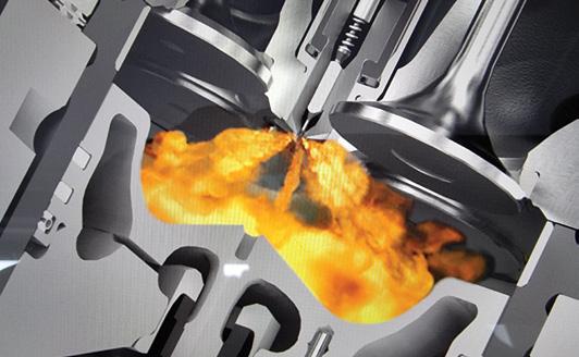
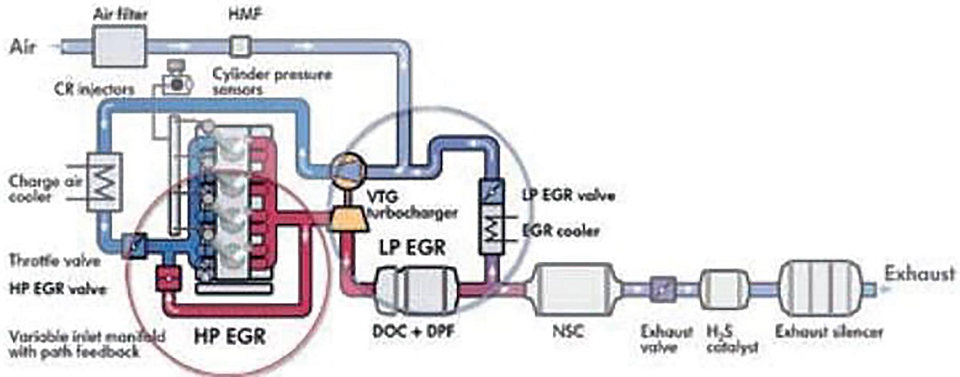
I have witnessed extensive changes to diesel engines – or to be more precise, diesel-fuel combustion and exhaust-gas treatment (pic 1).
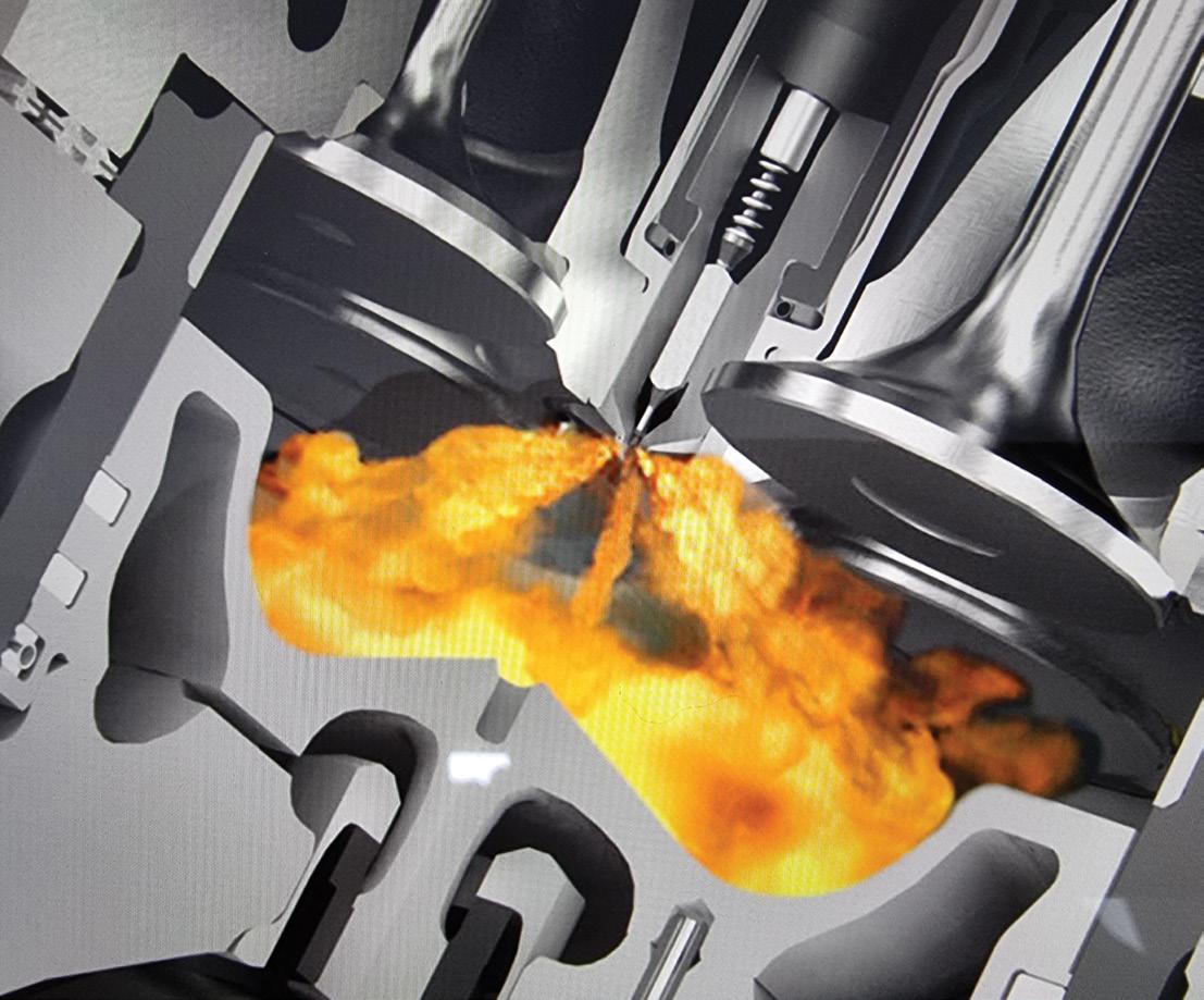
With untreated combustion, pic 2 clearly illustrates the necessity for DPF and SCR after-treatment. Unfortunately, the financial burden of meeting these emissions demands has become prohibitive.
Particulate matter (PM) refers to solid or liquid particles, some large or dark enough to be seen as soot or smoke. Most are fine particles composed of exceedingly small objects suspended in the air. Ninety per cent of diesel particulates, known as PM2.5, are less than 2.5 microns in diameter.
Carbon monoxide (CO) is a colourless, odourless gas, lethal at 0.5
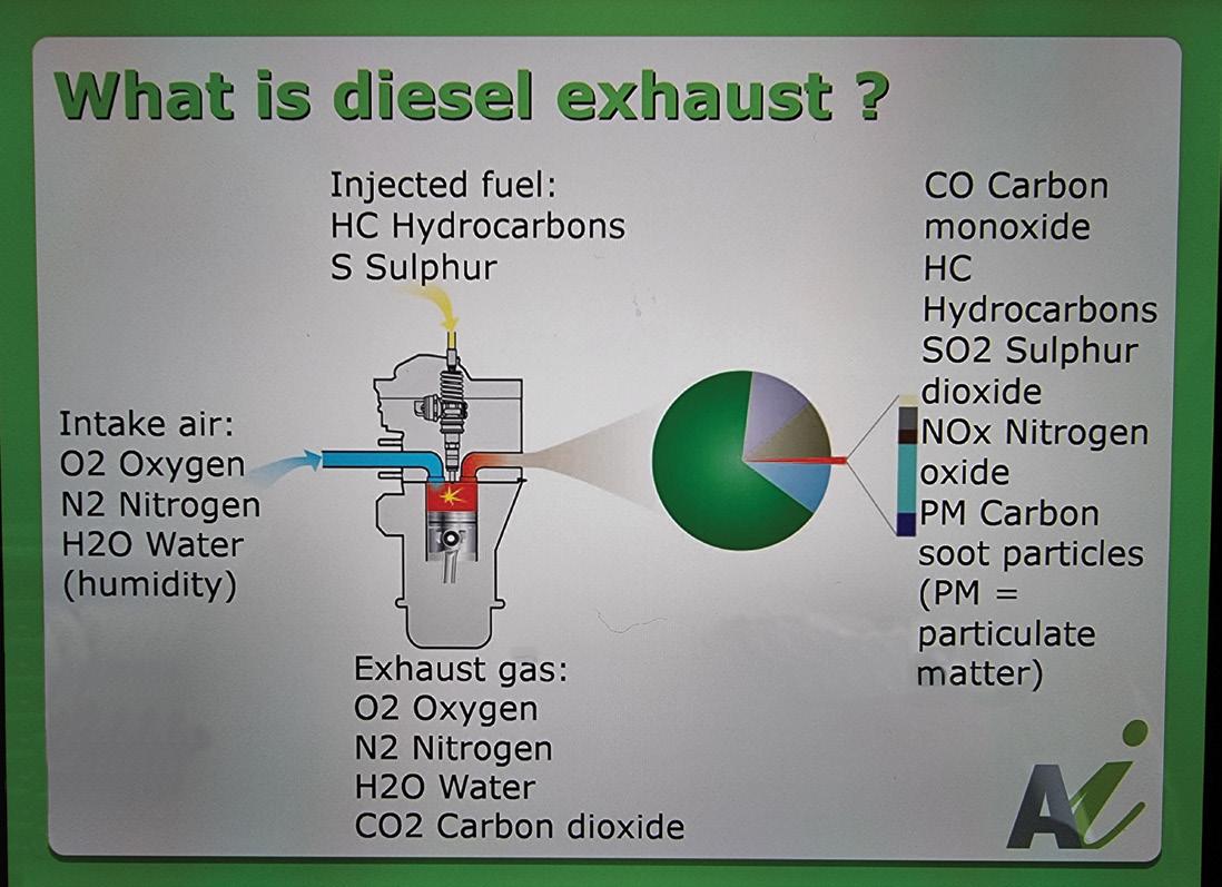
per cent by volume, produced by incomplete combustion of solid, liquid and gaseous fuels. The main source of CO emissions in the atmosphere is vehicles.
Nitrogen oxides (NOx) is the generic term for a group of highly reactive gases, all of which contain nitrogen and oxygen in varying amounts. NOx forms when fuel is burned at elevated temperatures during the combustion process.
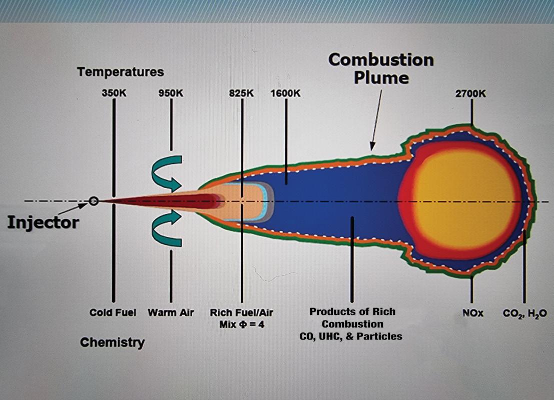
Hydrocarbons (HC) are chemical compounds that contain hydrogen and carbon. Hydrocarbon pollution results from unburned or partially burned fuel emitted from the exhaust due to incomplete combustion (pic 3).
Note: The temperatures shown are absolute (Kelvin), where 500K = 227°C.
The three phases of regeneration: Passive, active and forced
Exhaust gases are first treated or jointly treated by a diesel oxidation catalyst (DOC), which reduces CO and HC emissions.
Passive regeneration occurs within the DPF when critical conditions are met. Carbon is converted organically while passing through the porous DPF substrate.
Manufactured from ceramic or metallic compounds, the DPF substrate’s micro-thin wash coat of platinum, rhodium and barium converts carbon into carbon dioxide. This occurs without blockage
or significant change within the DPF. The most important condition is that temperatures remain between 300-500ºC.
Many budget DPFs have reduced catalytic area and often have insufficient or no active coatings.
Active regeneration is a powertrain control module (PCM) controlled targeted increase in exhaust-gas temperature. Pre-programmed parameters must be met for this process to occur.
You may recall factors such as fuel level, sensor failures triggering DTCs and carbon build-up increasing exhaust back-pressure.
If pressure levels become excessive, active regeneration will not take place. Carbon deposits are burned off or oxidised at around 500-600°C. However, a byproduct of this process is ash, which is calculated using an algorithm based on the number of regeneration cycles.
A great deal of emphasis is placed on exhaust pressure, air-mass calculation, EGR flow and temperature sensors. Therefore, it is essential that all relevant adaptation values are reset after any repair or component replacement.
Forced regeneration is strictly a software-driven request, available only as a workshop function. While it does have a place in dealing with DPF blockages, this process is proof of either system or user failure and should only be considered once all other causes have been addressed.
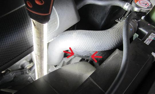
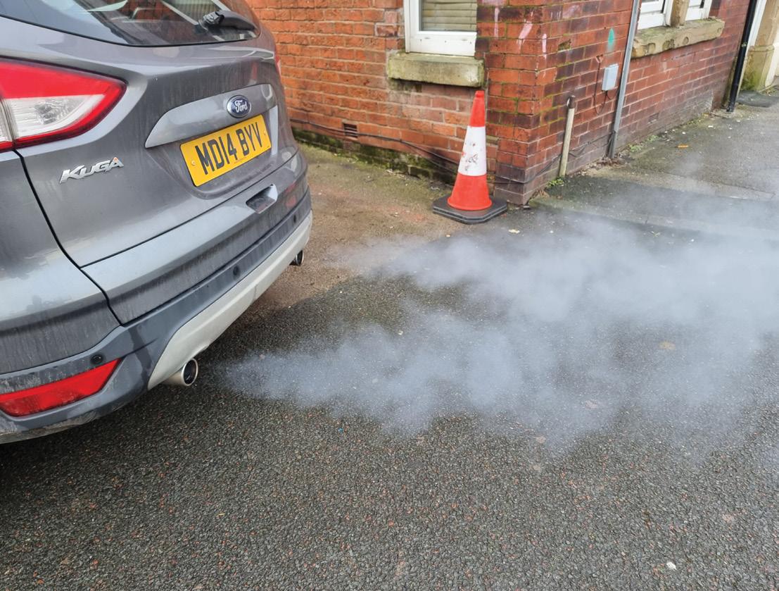
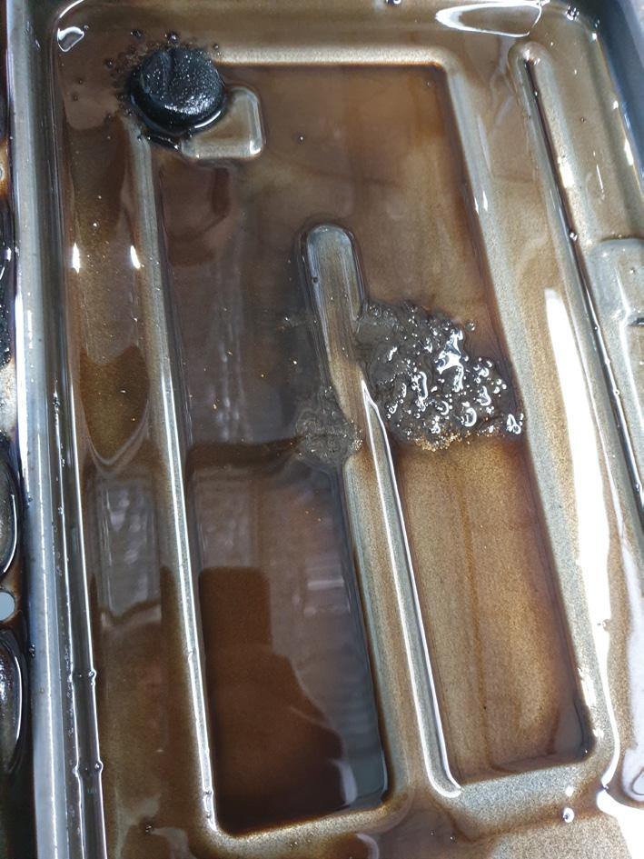
Are we really behaving responsibly towards global pollution? Look at this photo I recently took (pic 4).
The best method for DPF recovery?
The method of regeneration I personally support is off-car ultrasonic cleaning.
However, do not make the mistake of focusing only on the DPF. Other components such as EGR coolers, EGR valves, exhaust brakes, inlet manifolds and injectors also contribute to the problem. In fact, by the time you reach this stage of recovery, the engine requires a top-end de-coke.
This is exactly why a change in repair and servicing attitudes needs to be explained to vehicle owners. The end-of-life and financial criticality of a diesel vehicle arrives far sooner than many expect. Good luck convincing them!


Brendan Sorensen
Transmission fluid has evolved significantly over the past two decades, adapting to the demands of modern multispeed automatic, continuously variable transmission (CVT) and dual-clutch transmission (DCT) systems.
No longer just a simple hydraulic oil, today’s transmission fluids are engineered to serve highly specific functions – friction modification, wear protection, heat dissipation and precise pressure modulation. As automatic transmissions become more complex and sensitive to fluid characteristics, technicians must understand how transmission fluid degrades over time, what factors accelerate this process and how to accurately assess fluid condition in real-world workshop environments. In this article, we explore these key technical considerations in depth.
How transmission fluid degrades over time
Transmission-fluid degradation is driven by a combination of thermal stress, oxidation, mechanical shear, chemical depletion and contamination. Each of these factors reduces the fluid’s effectiveness, leading to poor shift quality, increased wear and potential failure of transmission components.
Thermal degradation and oxidation
Heat is the single greatest contributor to transmission-fluid breakdown. Most modern automatic-transmission fluid (ATF) formulations use Group III or Group IV synthetic base stocks, which provide improved thermal stability over older mineral-based fluids:

• Group III: Derived from crude oil but highly refined through a process called severe hydrocracking. This process uses high pressure, high temperature and a catalyst to break down, reshape and saturate hydrocarbon molecules, resulting in a highly stable, clean base oil.
• Group IV: True synthetic fluids, built from the ground up using polymerisation, typically starting with ethylene gas. These fluids offer superior oxidation resistance, thermal stability and viscosity retention under extreme conditions.
Despite these advancements, all transmission fluids degrade when exposed to sustained high temperatures:
• Fluid oxidation follows the Arrhenius equation, where every 10°C increase above 90°C doubles the rate of oxidation.
• Oxidised ATF loses its lubricating properties, leading to varnish formation on valve bodies and solenoids, causing erratic shifting.
• At 120°C, oxidation accelerates significantly, reducing fluid lifespan by more than 50 per cent.
• Over 130°C, ATF polymers break down

at a molecular level, forming sludge and deposits that clog narrow oil passages and disrupt hydraulic operation.
• At 150°C and beyond, friction modifiers burn off entirely, leading to increased clutch slip and rapid wear.
Many modern ZF, GM and Toyota transmissions may experience operating temperatures of 100-110°C under certain driving conditions such as during heavy load or high ambient temperatures. While these transmissions and their fluids are engineered to handle such conditions, sustained operation at the upper end of this range – or exceeding it – can significantly accelerate fluid degradation and potentially reduce transmission longevity, particularly without proper cooling or regular maintenance.
A known weak point
Many modern transmissions incorporate thermostatic-control valves in their cooling circuits, designed to delay cooler flow until reaching 80-90°C to improve warm-up efficiency. However, these valves can be troublesome.
The PX2 and PX3 Ford Ranger, equipped with the 6R80 transmission, has a notorious thermal-control valve prone to sticking, causing overheating. Many owners and workshops replace it with an aftermarket bypass valve for consistent maximum cooling, significantly reducing transmission temperatures during towing or off-road use. The only trade-off is a slightly longer warm-up period.
Service tip: When working on heat-sensitive transmission designs, consider installing an auxiliary transmission cooler or modifying the factory thermostat to activate earlier. Lowering peak ATF temperatures by just 10°C can double fluid lifespan in high-load applications.
Shear stress and viscosity breakdown
Transmission-fluid viscosity is critical for hydraulic actuation and proper lubrication. Automatics, CVTs and DCTs all require precise fluid flow to engage clutch packs, operate valve bodies and modulate mechatronic pressure control.
• Shear stability is a primary concern in modern ATF formulations. Even Group IV synthetic fluids experience viscosity loss over time due to extreme pressure cycling.
• Low-viscosity ATFs (Dexron HP, Toyota WS, Honda DW-1, ZF Lifeguard 8/9) reduce parasitic drag but are more susceptible to viscosity breakdown in high-shear environments.
• In CVTs, shearing occurs between belt/ chain-to-pulley contact surfaces –incorrect viscosity leads to excessive metal wear and belt slip.
Workshop assessment of shear breakdown
• Visual inspection
- Colour: Modern ATF comes in a range of colours, including red, green and amber. Dark brown or black fluid universally indicates oxidation. However, beware of GM’s 6T series of transmissions in the Cruze and Captiva, which have a very dark factory-fill due to a special additive, per a GM Technical Service Bulletin (TSB).
- Smell: A burnt odour is a sign of overheating and degradation.
- Debris: Visible particles or clutch material in the fluid indicate excessive wear.
• Blotter test
- Place a drop of ATF on a clean, white paper towel or blotter paper.
- Observe how the fluid spreads – dark or
uneven staining suggests oxidation and contamination.
• Scan-tool data
- Access transmission temperature parameter IDs (PIDs) and become familiar with adaptive shift-control strategy PIDs when doing auto servicing so you can start to learn what good versus bad looks like.
• Laboratory oil analysis
- With transmission-oil prices sometimes in the hundreds of dollars per litre, there is a strong case for using laboratory prognosis to measures viscosity loss, oxidation levels, additive depletion and wear metals to provide a precise assessment of fluid health.
Service tip: If a customer experiences jerky shifts or unusual clutch-engagement behaviour, perform a real-time adaptive transmission reset after replacing fluid. Many modern transmissions adjust shift pressures based on fluid properties and old fluid may have caused adaptive drift over time.
Friction-modifier depletion and clutch wear
Friction modifiers in ATF are designed to control clutch engagement characteristics, balancing high static friction for lock-up and low dynamic friction for smooth shifting.
• Fluid friction stability is critical –degraded friction properties lead to clutch-pack glazing or slip, causing shift flares and disengagement issues.
• ATFs in ZF 8HP, Mercedes 9G-Tronic and Ford 10R80 transmissions use proprietary additive packs to manage clutch-adhesion properties for precise shifts.
• Lab studies show that ATF subjected to 150,000km of driving loses up to 25 per cent of its friction-modifier content, leading to measurable clutch slip.
Addressing clutch shudder in the workshop
Many workshops have found success using Xado EX120 and similar treatments, particularly to remove early Honda Jazz CVT start-up clutch shudder.

Any more than a fine fuzz on the pan magnet is signs of trouble – this transmission has serious internal issues and is too far gone for just a fluid change.
Best practices for transmission-fluid service in the modern workshop
1. Use OEM or rigorously tested equivalent fluids: Universal fluids often lack manufacturer-specific friction modifiers tailored for each transmission.
2. Perform visual and lab-based fluid analysis: Early detection of oxidation, viscosity breakdown and contamination can prevent premature failures.
3. Reset adaptive transmission parameters after fluid changes: Many modern automatics rely on shift-pressure learning algorithms, which should be recalibrated after a fluid change.
4. Monitor ATF cooling efficiency using thermal imaging: External case temperatures can reveal cooling flow issues, particularly in sealed transmissions.
Modern transmission fluids are finely engineered to balance thermal stability, wear protection, shear resistance and friction control. However, these advanced formulations are still susceptible to degradation from heat, oxidation and mechanical stress.
By understanding how ATF breaks down, monitoring its condition effectively and implementing proper cooling and maintenance strategies, technicians can extend transmission life, improve shift quality and prevent costly failures.
For workshops striving to provide toptier preventative maintenance, integrating fluid analysis, adaptive resets and thermal diagnostics is paramount to ensuring longterm, reliable transmission performance.

Modern exhaust systems have come a long way from the days when exhaust gases were simply expelled into the atmosphere without any treatment.
In today’s world, stringent environmental regulations and heightened public awareness regarding air quality have driven significant advancements in exhaust after-treatment technologies.
One of the most critical components in a modern diesel vehicle is the diesel particulate filter (DPF), which plays a pivotal role in reducing harmful particulate emissions.
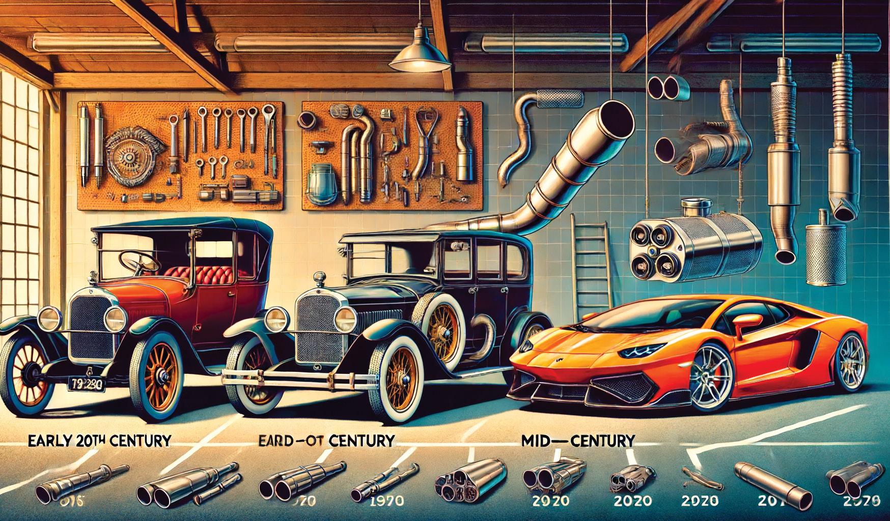
Evolution of exhaust systems
Modern exhaust systems are complex assemblies designed not only to channel gases away from the engine but mitigate pollutants that can harm both human health and the environment.
Over the past few decades, engineers have integrated a range of components such as catalytic converters, exhaust-gas recirculation (EGR) systems, selective catalytic reduction (SCR) units and DPFs to address various pollutants.
While petrol engines primarily rely on catalytic converters to reduce carbon monoxide, hydrocarbons and nitrogen oxides, diesel engines produce a significant amount of particulate matter (PM). This challenge led to the development and refinement of the DPF (pic 1).
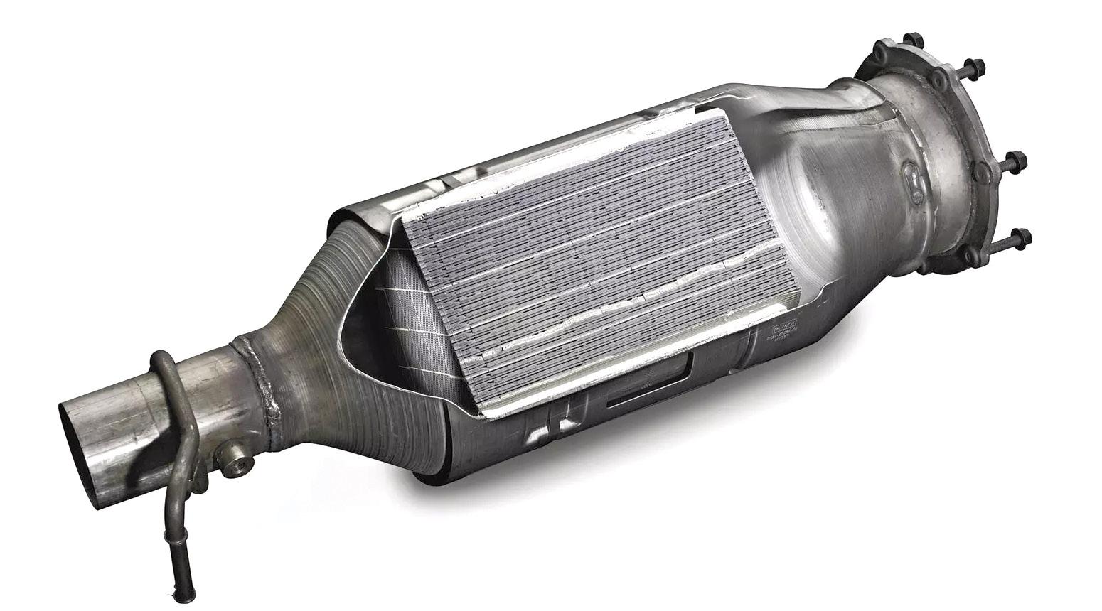
A DPF is engineered to capture and store soot and other PM produced during the combustion process in diesel engines. These particulates, if released into the atmosphere, contribute to smog and have been linked to respiratory and cardiovascular issues.
The DPF works by trapping these soot particles as exhaust gases pass through its porous structure. Over time, however, the accumulated soot must be removed to maintain the filter’s efficiency – a process known as regeneration.
At the heart of a DPF’s operation is a carefully designed matrix that allows exhaust gases to flow through while trapping solid particles. The filter’s walls are composed of high-temperature-resistant materials such as cordierite or silicon carbide, which provide a durable and thermally stable substrate for soot capture.
As the DPF collects soot, the efficiency of the engine’s back-pressure system can be affected, which is why regular regeneration is essential. Regeneration is a process by

which the accumulated soot is burned off at high temperatures, converting it into carbon dioxide and ash.
There are two primary methods of regeneration: passive and active. Passive regeneration occurs naturally during highway driving when exhaust temperatures are sufficiently high to incinerate the soot. In contrast, active regeneration is initiated by the engine’s control system when sensors detect increased backpressure in the DPF. During active regeneration, additional fuel is injected or other techniques are employed to raise the temperature within the filter, ensuring that the soot is effectively oxidised.
While DPFs have proven effective in reducing particulate emissions, they also present certain challenges. One significant concern is the potential for clogging if regeneration does not occur frequently enough or if the engine is operated under conditions that do not allow the filter to reach the required temperatures.
In city-driving scenarios, where stopand-go traffic is common, the opportunity for passive regeneration is limited. As a result, vehicles may require activeregeneration cycles more frequently, which can affect fuel efficiency and lead to increased maintenance needs.
Moreover, variations in fuel quality and engine operating conditions can influence the performance of DPFs. The use of biodiesel blends, for instance, can alter the characteristics of the soot produced, potentially impacting the regeneration process.
Advances in sensor technology and enginecontrol algorithms continue to address these issues, optimising regeneration cycles and ensuring the filter maintains its efficiency over the vehicle’s lifespan.
The DPF is not a standalone solution; it functions as part of an integrated system that includes EGR, SCR and catalytic converters. The EGR system reduces the formation of nitrogen oxides by recirculating a portion of the exhaust gases back into the combustion chamber, which lowers combustion temperatures. Meanwhile, SCR systems use a urea-based solution to convert nitrogen oxides into harmless nitrogen and water vapour.
Together, these technologies form a multilayered defence against a wide range of pollutants, ensuring modern diesel engines can meet stringent emissions standards while still delivering the performance and efficiency our customers expect.
The implementation of DPFs has had a significant positive impact on air quality in urban environments.
In regions with strict emissions regulations such as the European Union and North America, DPFs have helped reduce the concentration of fine particulates in the air.
This reduction has been associated with lower rates of respiratory diseases and other health issues linked to air pollution.
Furthermore, the success of DPF technology has encouraged further innovation in exhaust after-treatment systems, driving the automotive industry toward even cleaner and more efficient engine designs.
Looking forward, the evolution of DPFs is likely to continue as manufacturers strive for greater efficiency and reliability.
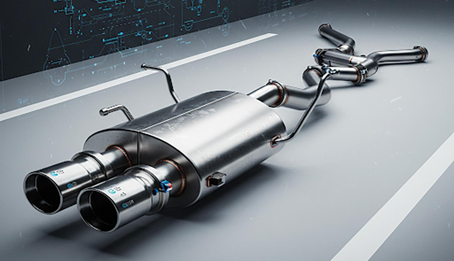
Research is ongoing to develop filters with lower regeneration thresholds and improved durability. Additionally, advancements in materials science and sensor technology are expected to enhance DPF performance, reducing the need for frequent active regenerations and minimising the environmental impact of maintenance procedures (pic 2 and 3).
As global emissions standards become increasingly strict and the push for sustainability intensifies, the role of the DPF and related technologies will remain crucial. While the automotive landscape is also shifting toward electric and hybrid powertrains, diesel engines equipped with advanced DPFs and integrated emissions-control systems are expected to continue serving as a reliable option in various segments, particularly in heavy-duty applications.

Modern exhaust systems represent a triumph of engineering, balancing the demands for performance, efficiency and environmental responsibility.
DPFs, as a key component of these systems, demonstrate how targeted technological solutions can address specific environmental challenges. By capturing and periodically burning off harmful particulate matter, DPFs not only help vehicles comply with rigorous emissions standards but contribute to cleaner air and a healthier environment.
As technology advances and regulatory requirements evolve, the ongoing refinement of DPFs will play an essential role in shaping the future of sustainable transportation.

Clinton Brett
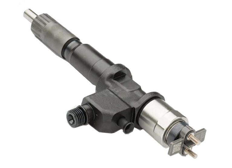
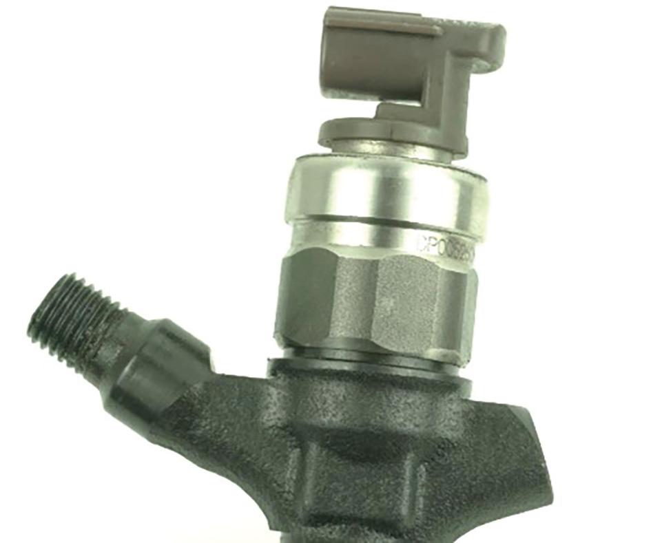
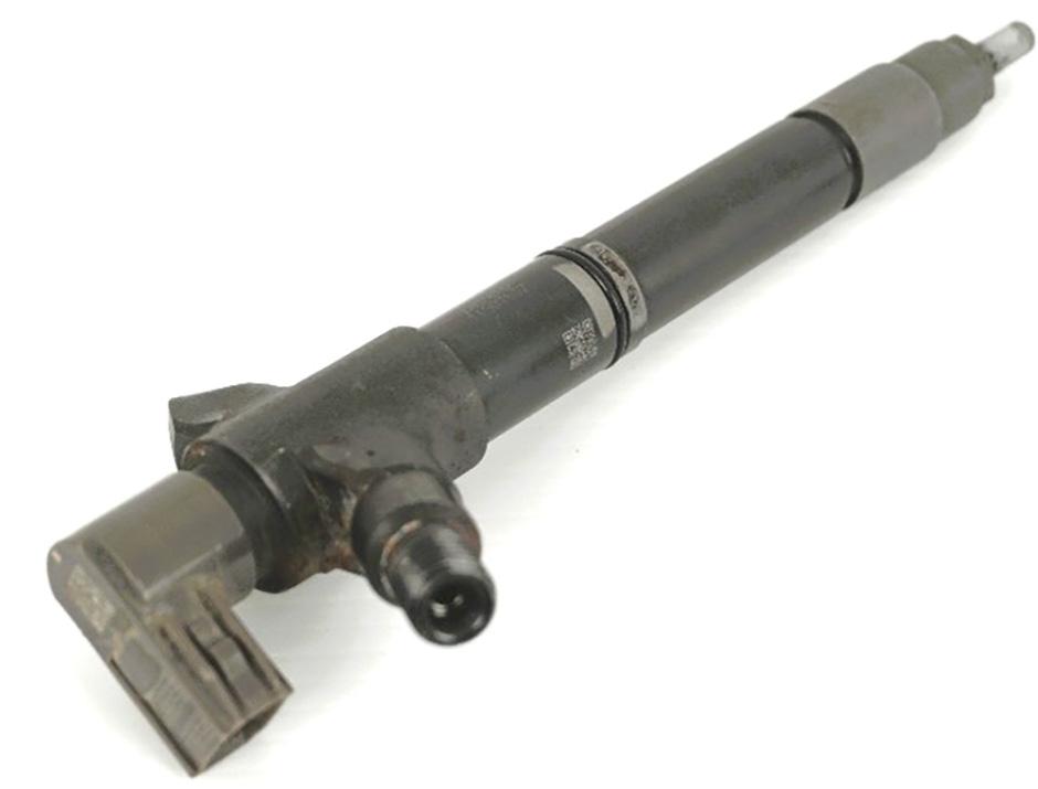
In part four of this series on fuel-control valves, I’m going to share what I have learnt from working with the Denso common-rail diesel (CRD) system, focusing on the brand’s injector design (pic 1), identification and diagnostic strategies.
I was fortunate to have gained experience working with European OEMs before Denso products were in the mix. One benefit of these injectors that differed greatly from Bosch, Delphi and Siemens was the ability to read valuable data that we had not seen before on aftermarket scan tools at the time. Denso launched its first CRD system in 1995 and since then has been actively involved in developing advanced diesel-engine technologies to meet customer needs and stringent worldwide emissions regulations. The brand provides a broad range of diesel fuel systems for everything from heavy-
correction code given to the injector during manufacturing is programmed into the ECU. Something was recently brought to my attention by several of my Denso dieselinjection dealers – a new release by the OE manufacturer, an injector with one code suits all (pic 4).
replacing injectors. By having this system in place, the OEM was able to ensure the emissions were met when the injectors were fitted to the engine.
CRD injector correction coding is important and allows the system to compensate for mechanical and hydraulic tolerances within the injector. No two injectors will naturally flow the same and the vehicle ECU can compensate for this by altering the pulse width to individual injectors when the
Does this mean injector coding has been a waste of time from the beginning?
Personally, I wouldn’t trust an injector using the same code for all cylinders, especially when once upon a time the manufacturer stipulated and enforced that we enter codes each time an injector was removed and replaced.
I’ve been informed the intention of this product is it’s only suitable for older, higherkilometre engines where tolerances are not as crucial.
Try explaining that to your customer when they have just forked out a couple of thousands of dollars for a set of injectors. We all know that as soon as you install these injectors, you are now entirely responsible for the warranty – not the supplier, not the manufacturer and certainly not your customer, just you.
Imagine requesting a warranty of the failure? Does the Denso supplier question the reliability of an engine with high kilometres? At the time of publishing this issue I hadn’t been able to verify this one-code system. I trust Denso will get back to me in due course or have its own press release to assist customers.
Identifying features – Denso electromagnetic Commonly fitted to light vehicles, including Toyotas with the 1KD-FTV 3.0-litre D4D engines (2005 to 2015 HiLux, HiAce and Prado and the LandCruiser 1VD-FTV V8), as
well as the Mitsubishi Pajero and Triton, Ford Transit and Mazda models.
John Deere has been the most popular off-highway application to adapt Denso, along with Case (earth-moving), Komatsu, Isuzu, Hino, and some Fuso models (heavy transport).
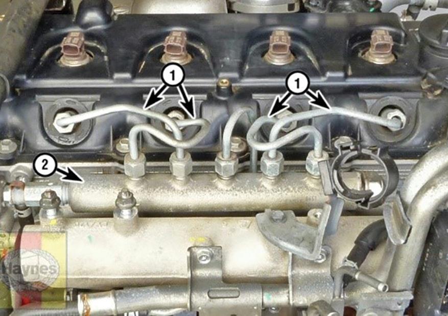
Most Denso injectors use a banjo bolt to secure a steel rail as a way to seal the injector-return fuel. The inlet-fuel connection is part of the cast body (pic 5).
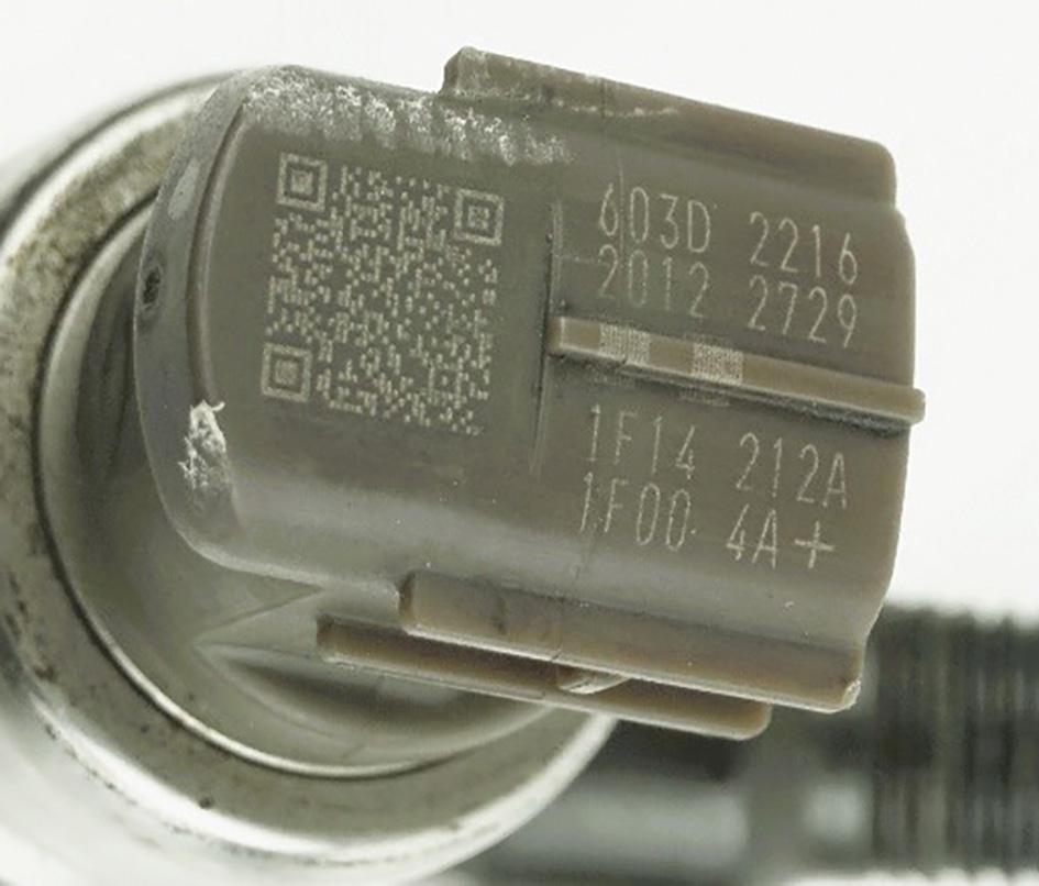
The part number can be located on the body itself, which in most cases is located in the sleeve of the cylinder head, making it nearly impossible to locate the part number without removing the injector from the engine. It is important to go by the vehicle’s chassis number.
However, in the case of an engine replacement – which has been far too common for the Toyota HiLux 1KD-FTV and LandCruiser 1VD-FTV V8 – you must be 100 per cent sure the correct injectors are being fitted. This is because these engines will still start and run even if the injector codes are not entered. Failure could occur at any time if the incorrect injectors are fitted.
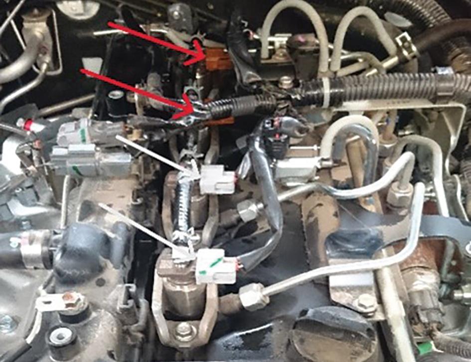
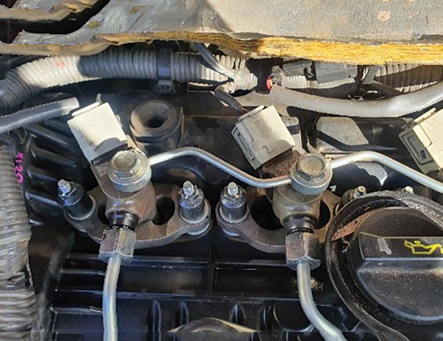
- Engine-bay ID
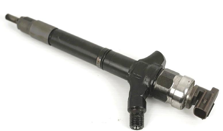
• Nissan Navara YD25 (pic 6)
• Toyota LandCruiser 1VD-FTV V8 (pic 7)
• Mitsubishi Triton 4N15 (pic 8)
Denso piezo electric-actuator injector
Development of Denso piezo injectors was already in the fray when the brand first released electromagnet solenoid injectors. But we did not see its dominant presence until they were fitted to popular Toyota models. This was from around 2015 onwards, with models including the 1VD-FTV
LandCruiser 4.5-litre V8 fitted with a DPF (pic 7) and HiLux, HiAce, Fortuner and Prados with the 1GD-FTV 2.8-litre and 2GD-FTV 2.5-litre engines. Other OEM fitments include Mazda, Mitsubishi, Isuzu and other models.
- Toyota LandCruiser 1VD-FTV V8 injector
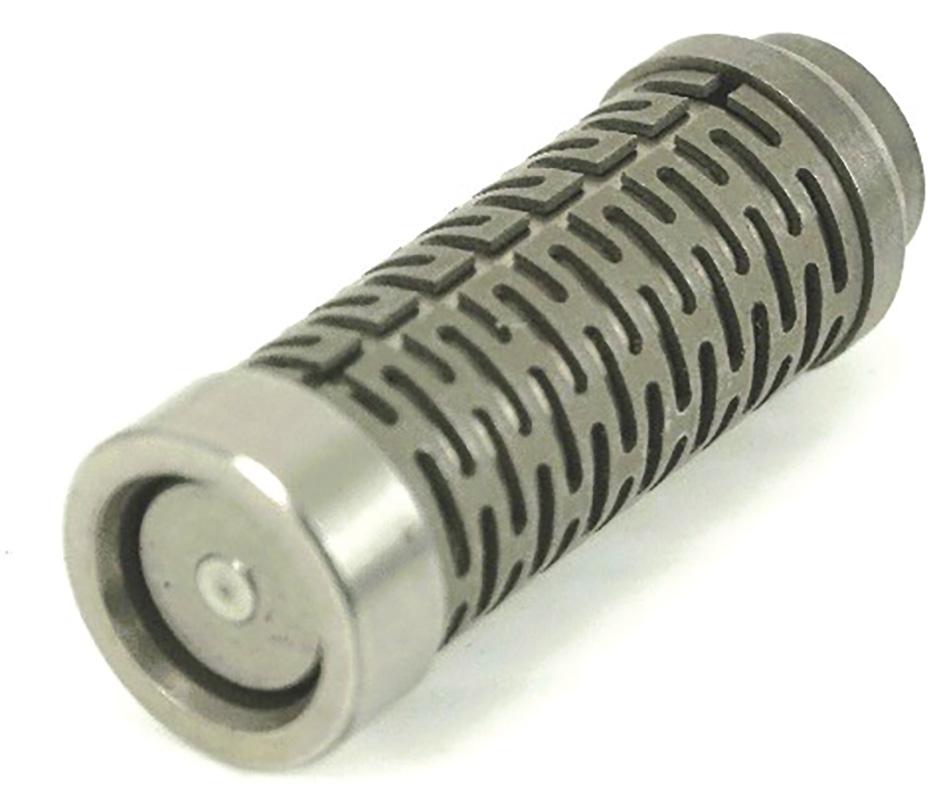
• Piezo injector (pic 9)
• Piezo stack (pic 10)
Two-wire piezo injector harness
The later Denso piezo injector also incorporates an internal pressure sensor in each injector. This can be determined by a group of six wires for each injector (pic 11).
Diagnosing Denso injectors
I was fortunate to discover injector feedback values early in 2005 soon after the release of the Toyota HiLux 1KD-FTV engine in Australia. However, my understanding of this diagnostic process did not occur overnight. It took me almost five years to be confident in utilising the values to assist with diagnostics. But be aware, some of the other Denso OEM applications have introduced their own unique strategies. For example, Mitsubishi small-quantity pressure values – now that system took me a little longer to get my head around.
What is injector feedback and how is it determined?
In an attempt to keep this simple, I call this the ‘buddy system’, meaning each injector has a buddy injector (pic 12). Like having a small group of buddies, they’ve always got your back.
Typically, a four-cylinder engine will have cylinders #1 and #4 at top dead centre (TDC) at the same time as cylinders #2 and #3 are at bottom dead centre (BDC). Cylinders #1 and #4 are buddies and #2 and #3 are buddies.
However, from 2011 on, the 1KD-FTV changed this strategy to buddies #1 and #2 and buddies #3 and #4. They are all linked to assist in balancing the engine, preventing misfires, uneven temperature displacement, vibration and erratic uncomfortable conditions. If one cylinder has less or too much fuel or air, the buddy injector will adjust to compensate.
The engine sensors are monitoring these changes in each cylinder and sending signals back to the ECU, which is then demanding each injector alter the fuel injection quantity injected on each stroke. How does it know when compression is too high or too low?
• Crank-angle sensor knows the position of the piston and the speed it is moving.
• Cam-angle sensor knows which valve is open or closed.
• Microphonic sensor (knock sensor) listens for combustion.
• Less air in the cylinder means less resistance and the piston moves much quicker.
• More fuel being injected means higher resistance and the piston moves slower.
• ECU is sending current; therefore it knows which injector is operating at the time.
• ECU has each injector code stored in the memory.
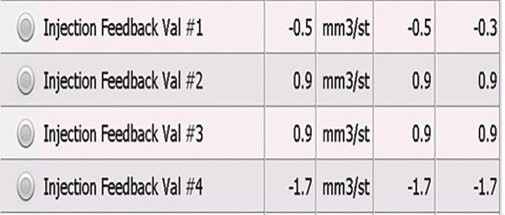
The injector values will display positive (+) and/or negative (-) figures. Not all scan tools read feedback values and not all manufacturers enable this function.
The manufacturer is aiming for zero quantity feedback across all cylinders. You may notice on different scan tools they display a unit next to the number. This could be ms (milliseconds), cm3 (cubic centimetres), mL (millilitre) or mm/3st. To simplify, only look at the numeric figure.
First test with engine cold (first start-up) at idle and then when warm and operating at idle.
• Failed injector: +5.0.
• The buddy (compensating) injector will be -5.0.
• Early Toyota with harsh rattle: +1.7 or more.
• Compression becoming a concern: -1.7. But the most important thing to remember, understand the typical diesel symptoms and how the engine is supposed to run.

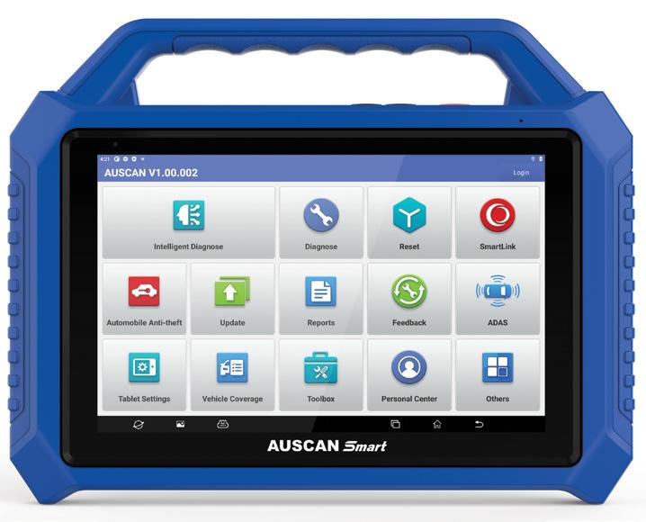
Automotive technology is evolving at an unprecedented pace and technicians need advanced, reliable tools to keep up.
Enter the AUSCAN Smart, a next-generation intelligent diagnostic scan tool designed to empower both professionals and enthusiasts with a powerful suite of capabilities.
The AUSCAN Smart has been designed to redefine vehicle maintenance by combining comprehensive car and truck diagnostics with immobiliser (IMMO) functions, online coding, anti-theft matching, online programming, advanced driver-assist system (ADAS) and remote diagnostics.
Unmatched coverage and intelligent diagnostics
One of the standout features of the AUSCAN Smart is full-system coverage across 110 manufacturers spanning Australian, US, Asian and European markets.
This broad compatibility enhances its intelligent diagnostic ability, which automatically identifies vehicle identification numbers (VINs), reducing diagnostic time and streamlining system access.
And to make it even better, all car and truck
software comes with three years of free updates.
The topology-graph functionality further elevates the AUSCAN Smart’s capabilities, offering a visual representation of the vehicle’s communication network and allowing technicians to quickly pinpoint faults – crucial when accuracy and efficiency matter most.
The AUSCAN Smart is equipped with more than 30 essential maintenance functions to simplify complex tasks such as antilock braking system (ABS) bleeding, diesel particulate filter (DPF) regeneration and exhaust-gas recirculation (EGR) adaptation, ensuring compliance with strict environmental regulations.
Its dual-mode wireless vehicle communication interface (VCI) supports major testing standards, while remote-diagnostic capabilities extend its use beyond the workshop.
Continuous updates and support for expansion modules such as tyre-tread
detection and immobilising functionality make the AUSCAN Smart more than just a diagnostic tool – it’s a comprehensive automotive solution.
Features such as anti-theft matching and ADAS calibration further enhance its versatility, making it indispensable in today’s rapidly evolving automotive landscape. With its sophisticated yet user-friendly design, the AUSCAN Smart is engineered to ensure technicians stay ahead of modern vehicle complexities, delivering precision, efficiency and reliability in every diagnostic task.
AUSCAN Smart is exclusively distributed by SmartSafe Australia, a division of Launch Tech Australia.
• Find out more at smart-safe.com.au or call 1300 369 788

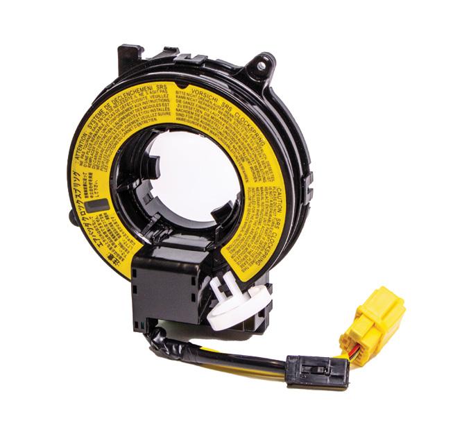
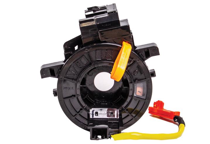
Aclock spring is a vital electrical component, responsible for maintaining a continuous connection between the steering column and steering wheel, airbag, horn and other electrical components.
A clock spring is a coiled wire wound around and housed in a protective casing. When the steering wheel is turned, the clock spring uncoils and recoils, allowing the wires to stretch and contract without breaking.
Over time, the clock spring can wear out or become damaged, leading to issues with the airbag or other electrical components. One of the most common symptoms of a faulty clock spring is the airbag light staying on.
If the airbag or supplemental restraint system (SRS) light is on due to a broken clock spring, the vehicle’s airbags will not deploy if involved in an accident.
A scan tool is sometimes necessary to reset the steering-angle sensor (SAS) if it has been removed to replace the clock spring. In some applications the SAS may be integrated within the clock-spring assembly itself.
In vehicles fitted with electronic stability control/electronic stability program (ESC/ESP) or traction control system/electronic traction system (TCS/ETS) technology, the SAS function determines the position of the steering wheel. This data is used by these systems and the anti-lock braking system (ABS), with the steering-wheel position is reported in degrees.
minutes before replacing or disconnecting any airbag components.
How to know when the clock spring has failed
These are some of the most common problems experienced when a clock spring fails.
• Airbag light on: This common problem is often caused by a defective clock spring and may be accompanied by any of the following errors:
- Driver airbag squib circuit high resistance.
- Airbag circuit resistance is too high.
- Driver-side airbag circuit high resistance or open.
- Driver squib circuit open.
• Horn doesn’t work: A bad clock spring can cause the horn to stop working.
• Cruise-control switch doesn’t work: Cruise-control functions are mounted on the steering wheel in many vehicles. If so,
the cruise-control wires will be routed via the clock spring.
• Steering-wheel buttons don’t work: The radio or stereo performs adequately but can no longer be controlled from the steering wheel.
• A rubbing noise when the steering wheel is turned: This is one of the early warning signs a clock spring is starting to fail.
• ESC/ESP/ETS/TCS light on: These systems require steering-angle position data and that function is integrated inside the clock spring on certain vehicles.
If a vehicle is experiencing one or more of these issues, the clock spring may be defective.
Can a clock spring be repaired?
No – most clock springs cannot be repaired successfully. If a clock spring fails, replacement is the best solution.
• To find out more about the new PAT Premium Clock Spring range, call 1300 472 872.


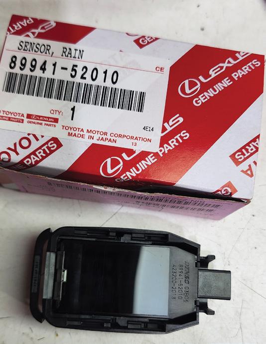
This vehicle came into the workshop with the auto mode for the wipers not working.
When auto was engaged, they would perform just a single wipe, then nothing. Low and high speeds worked fine.
Confirmed the fault. All other wiper functions checked out but in auto mode the wipers did only wipe once when engaged, then refused to operate again.
Adjusting the auto mode’s sensitivity levels and pouring water directly onto the windscreen at the sensor had
no effect. The customer was unsure if the windscreen had ever been replaced.
Connected a scan tool to check if the body control module (BCM) was detecting the sensor but could find no options for it.
Removed the rain sensor for inspection and discovered tapping or lightly shocking it temporarily restored normal function.
Further inspection revealed a light oily/gel residue on the sensor’s face. Wiping this residue occasionally allowed the sensor to work again. Wiggling the connector made no difference.
Confident the sensor was faulty, I ordered a new OEM one. Comparing old and new sensors confirmed the issue –there was a missing gel layer on the faulty sensor, likely from a previous windscreen


replacement. This air gap prevented the sensor from detecting moisture correctly. Installed the new rain sensor and the auto wiper function worked immediately once water was poured in front of the sensor.
Diagnostic time for this job was two hours and repair time was 30 minutes.
Jayde
Moore
Albert’s
Auto Electrical SMITHFIELD, NSW

Customer complaint
High-voltage (HV) warning lights were displayed on the dash and the vehicle was unable to engage ‘Ready’ mode. The vehicle was towed in for diagnosis.
Problem summary
Confirmed the vehicle would not go into Ready mode. Everything else appeared to be working (lights, dash warnings, etc).
Diagnostic sequence
Performed a full system scan and retrieved the code, P0AA6 – Hybrid battery voltage system isolation fault.
Further investigation using freeze-frame data showed extended codes of 526 and 612.
When an isolation fault is detected, the trouble code, P0AA6 – Hybrid battery voltage system isolation fault is stored. Additionally, an information code 526 is set at the same time.
Once the driver attempts to restart the car, the HV ECU performs a test to identify which section of the system is shorted to ground. This results in a second locationspecific information code – in this case, 612 was logged.
P0AA6 can have several ‘information’ codes. Information codes are also known as INF codes or sub-codes. Without these, the DTC is too vague to properly (or efficiently) diagnose the cause of the P0AA6.


INF code – Description:
• P0AA6 – 526: This code can be safely ignored. It is set whenever P0AA6 is triggered and provides no additional information.
• P0AA6 – 611: Indicates a short to ground within the electric a/c compressor, cables or connector. It is crucial to run the a/c during a test drive, otherwise this code will not set.
• P0AA6 – 612: If the fault is on the battery side of the system main relays, an INF code 612 is triggered. Look for electrolyte leakage around the battery terminals or any moisture inside the battery pack.
• P0AA6 – 613: Indicates a fault with the motor windings, motor cables or the output side of the IPUs. This is typically caused by a motor/generator winding grounding to the stator back-iron.
• P0AA6 – 614: If there is a fault with the DC cables running from the battery to the inverter, or with the inverter itself, INF code 614 is set. DC cables can be damaged in a collision. Because they are shielded cables, damage to the insulation can cause an isolation fault, sometimes without visible signs. Faults in the inverter are usually due to coolant contamination or other foreign material.
• P0AA6 – 655: This code applies only to all-wheel-drive vehicles. Toyota uses an additional motor/generator to drive the rear wheels on many AWD models.
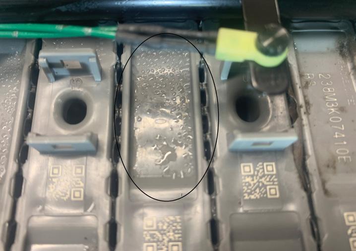
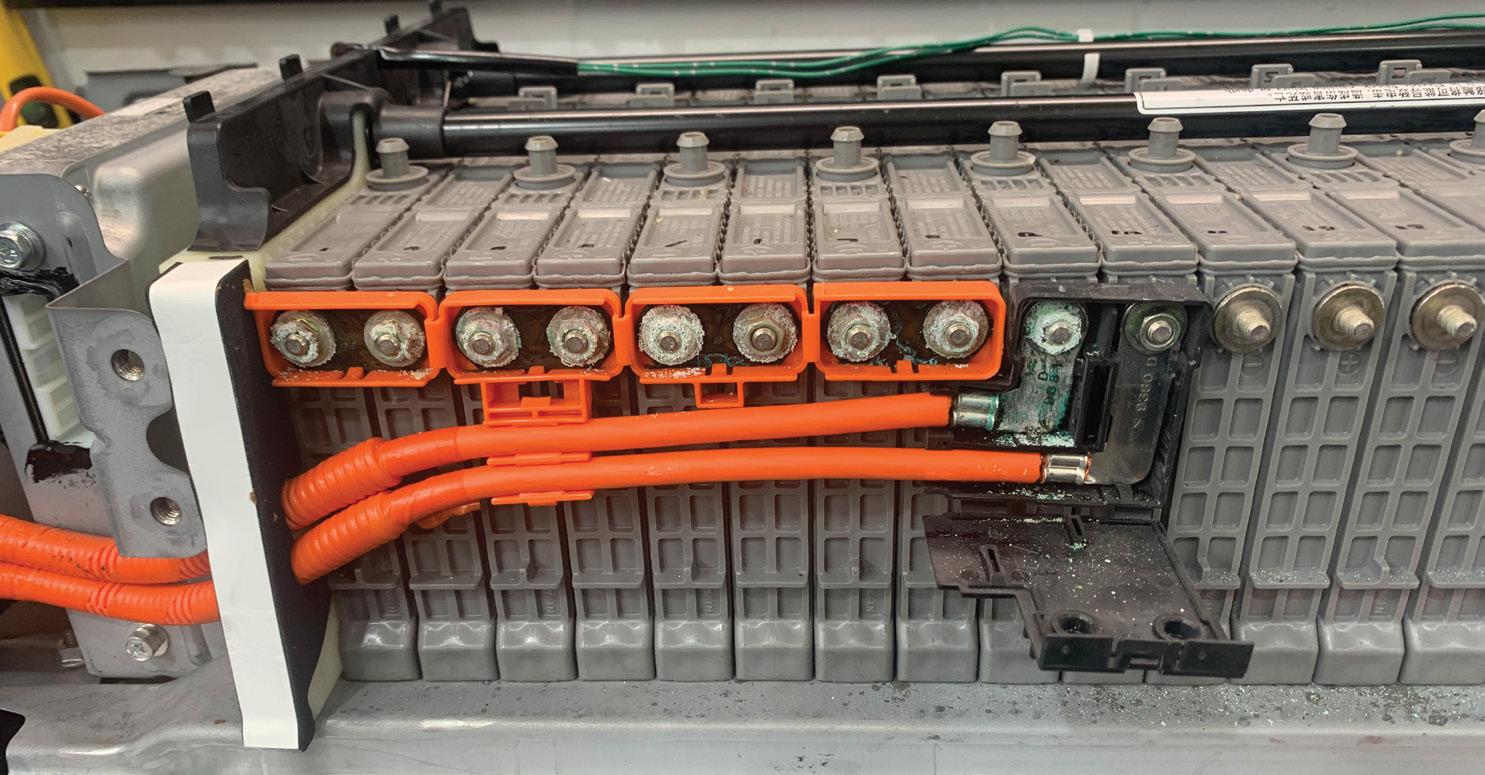
After removing the rear trims to access the HV battery pack, noticed moisture under the carpets and surrounding areas.
Stripped down the battery pack once the vehicle was safely de-powered (following the live-dead-live procedure), which revealed significant moisture on and around the batteries and connectors (pic 1, 2, 3 and 4).
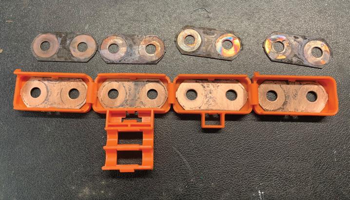
This moisture was causing electrical leakage, which resulted in the system shutting down for safety reasons.
Fault description
Excessive moisture in and around the HV battery.
Fault solution
Performed a full strip-down, thorough cleaning and drying of the affected components.
Dried out the complete interior before reinstalling the HV battery pack.
Diagnostic time was one hour, taking into account preparation and research. Repair time was two hours, taking into account the location of parts and carrying out the repair to a tested outcome.
If your particular scan tool does not show Toyota INF codes in the code read/ description, check for a data parameter ID (PID) ‘Detail Code 1’. This is the INF code that relates to fault code 1, Detail code 2 relates to fault code 2 and so on.
Repair Solution by TaT Tech Team member Jeff Smit.
Customer complaint
The vehicle’s check-engine light (CEL) was on.
The vehicle had no driveability symptoms.
Problem summary
A full vehicle scan retrieved the following code:
• P2096 – Post catalyst fuel trim lean. I knew this was a common powertrain control module (PCM) software calibration update that was required for many Mazdas. However, I had only carried out the update on BL Mazda 3s using the Mazda USA portal as Mazda Australia currently has unreasonable terms regarding calibration updates.
I was unsure if using the US portal back door in Australia would be successful for this model.
Diagnostic sequence
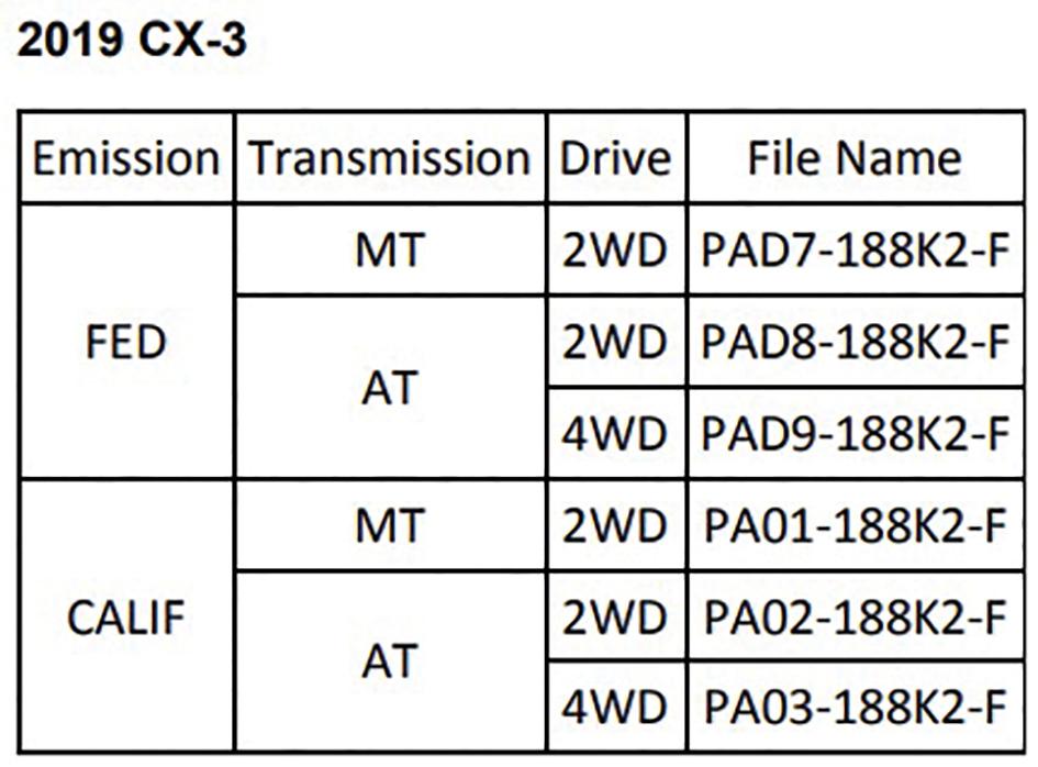
I googled ‘CX-3 P2096 update NHTSA’, knowing the National Highway Traffic Administration (NHTSA) in the US often posts common Technical Service Bulletins (TSBs), making this my easiest path rather than my second option of paying for a shortterm Mazda Australia data subscription. Halfway down the first page of Google results I saw an NHTSA TSB PDF file (Mazda TSB 01-012/20), which detailed that a PCM calibration update was a fix for various models such as CX-3, CX-5, MX-5, Mazda 3 and Mazda 6 from VIN ranges starting 20182020.
Unfortunately, because this was a US TSB, the calibration file numbers given for the CX-3 for US Federal and California emissions (pic 1) had a very different number structure to my Australian calibration file

number, which I accessed via the ‘ECU information’ tab in generic OBD on my Autel scan tool.
Despite this, I was confident I was on the right track. My confidence was bolstered when freeze-frame data for the code showed good fuel trims of short-term minus two and long-term minus one.
In my bay, live data, including fuel trims, all looked fairly normal, with nothing standing out at various load ranges. I did note from the service history that this vehicle had not covered a lot of kilometres per year, but the rear oxygen (O2) sensor was quite steady around 700 millivolts (mV) even at high loads, so I was confident the catalyst was in reasonably good condition.
Rather than paying for a short-term Mazda USA programming subscription as I had done previously for Mazda 3s, I remembered a Facebook post from Josh at The Automotive Clinic in Melbourne that mentioned this calibration can often be carried out with Forscan.
Forscan is a free PC-based open-source scan-tool software for Ford and Mazda vehicles, similar to VCDS for VW/Audi, and is often favoured over the factory Ford/Mazda software for areas that it is competent in.
Paying a measly $20 a year allows access to certain advanced features such as PATS configuration for immobiliser-based issues and module configuration and programming. While this is cloud-based programming, meaning it checks the VIN and grabs the latest calibration file that Forscan has on its cloud regardless of whether there is a later version available on the true Ford servers, it is still a great option, particularly for common fault-calibration update issues when you are familiar with which calibration iteration
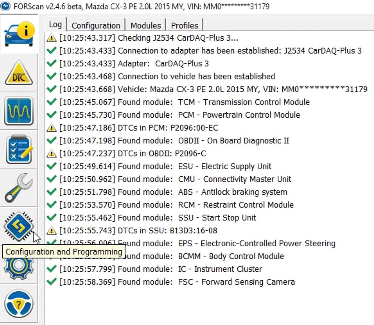
(usually the ascending letter at the end of the number) is high enough to sort your issue.
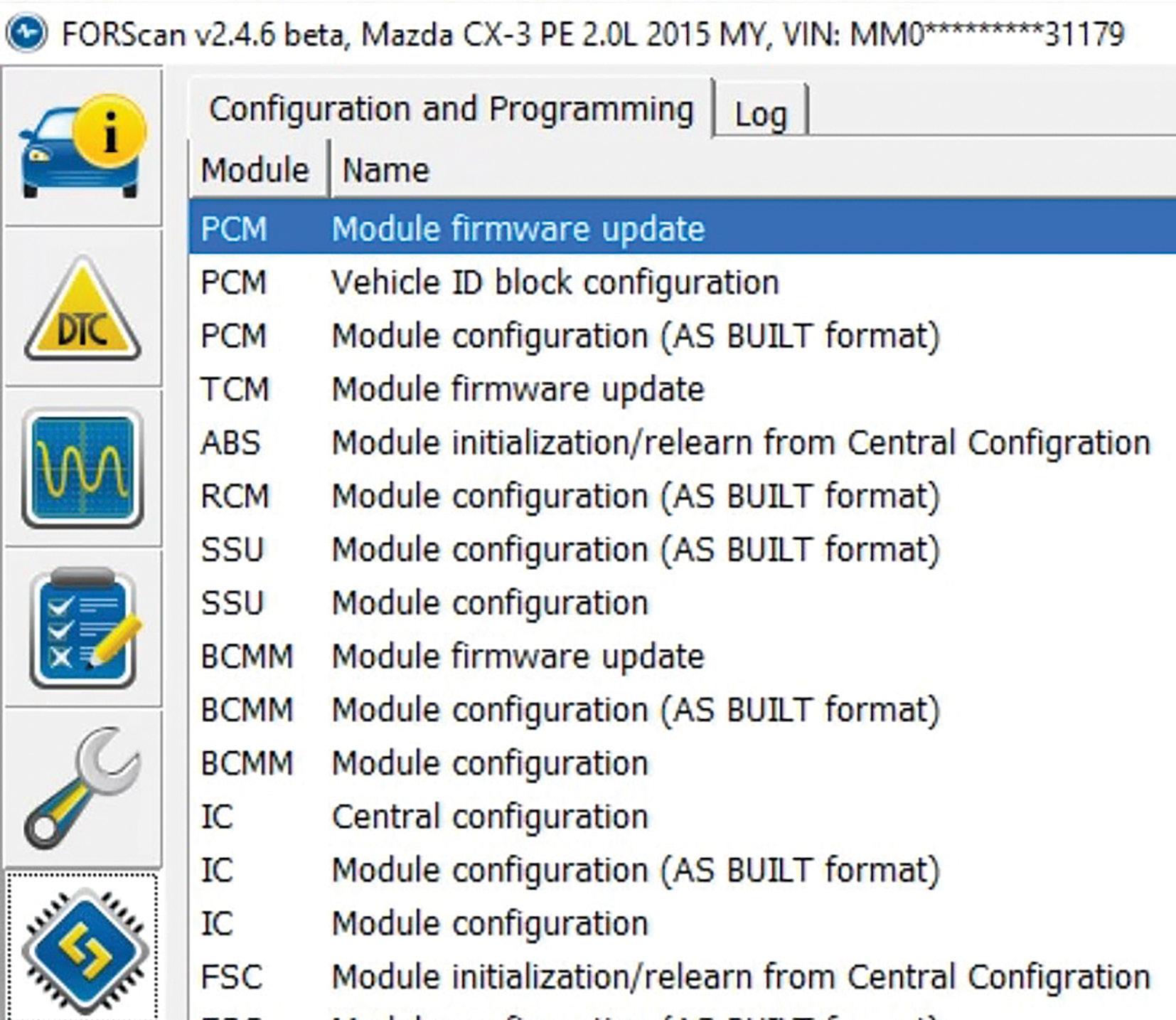
With my power stabiliser already connected to the vehicle’s battery from the start of the job, and using my Cardaq 3 (cheaper single-protocol dongles can also be used with Forscan), I accessed ‘Configuration’ and ‘Programming’ (pic 2) and confirmed the ‘PCM Module Firmware Update’ (pic 3) option was available for this model and there was a later calibration file available, upgrading this vehicle from ‘B’ to ‘C’.
This gave me the confidence to sell the job to the customer and I knew I could always chance the US Mazda portal if it failed.
Programming jobs in our shop are sold at a one-hour labour rate plus the subscription fee. I sold this job at our full Mazda OEM programming rate, even though I was using Forscan, and was able to complete the job within 15 minutes. I have no problem justifying this – after all, we don’t actually sell labour time, we sell solutions.
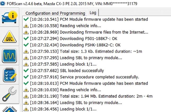
I carried out the job by continuing in Forscan’s PCM Module Firmware Update, clicking ‘Download’ to download the file and then clicking ‘Test Run Secondary Boot Loader (SBL)’ rather than just jumping into programming.
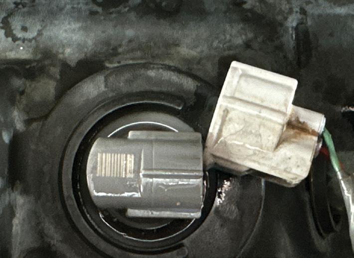
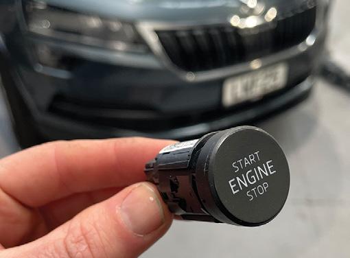
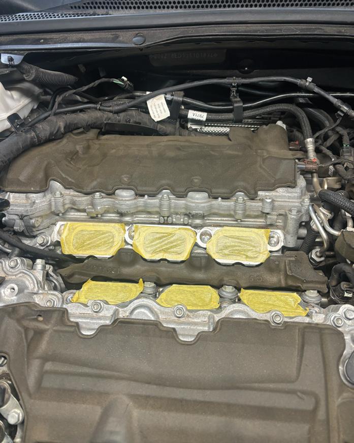
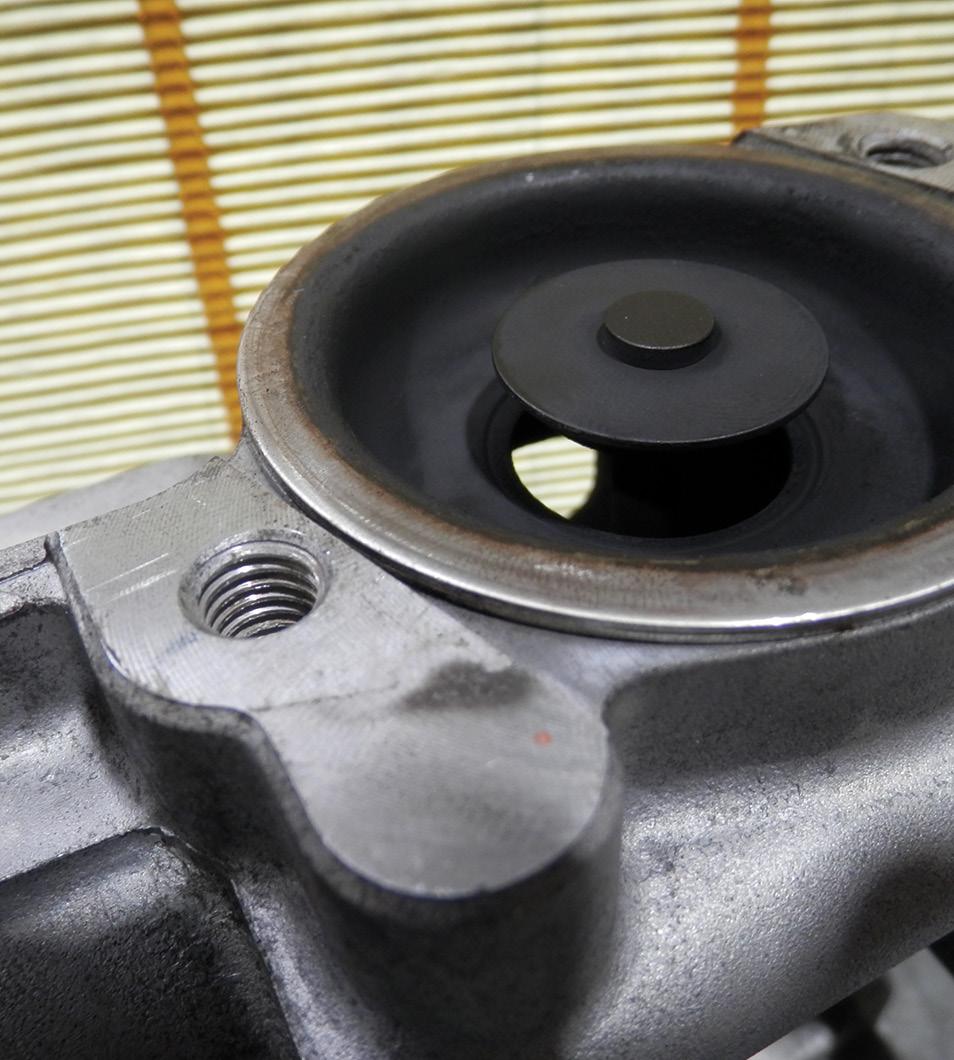
Customer complaint
The engine would not crank over and lights were going out on the dash and information display when trying to start the engine.
Problem summary
A service and other repairs had recently been performed by the customer’s local repairer.
The customer had picked up the vehicle and stopped at the shopping centre on their way home, only to find the vehicle would not start when they returned.
When the brake pedal was depressed and the start button was pressed, all of the dash lights and information centre display would turn off and stay off for a few minutes.
Diagnostic sequence
Connected a scan tool but found no fault codes.
Tested all fuses, ECU power and grounds and found a missing 5V reference from the ECU.
Disconnected all engine sensors that used a 5V reference to see if any shorted sensors impacted the ECU.
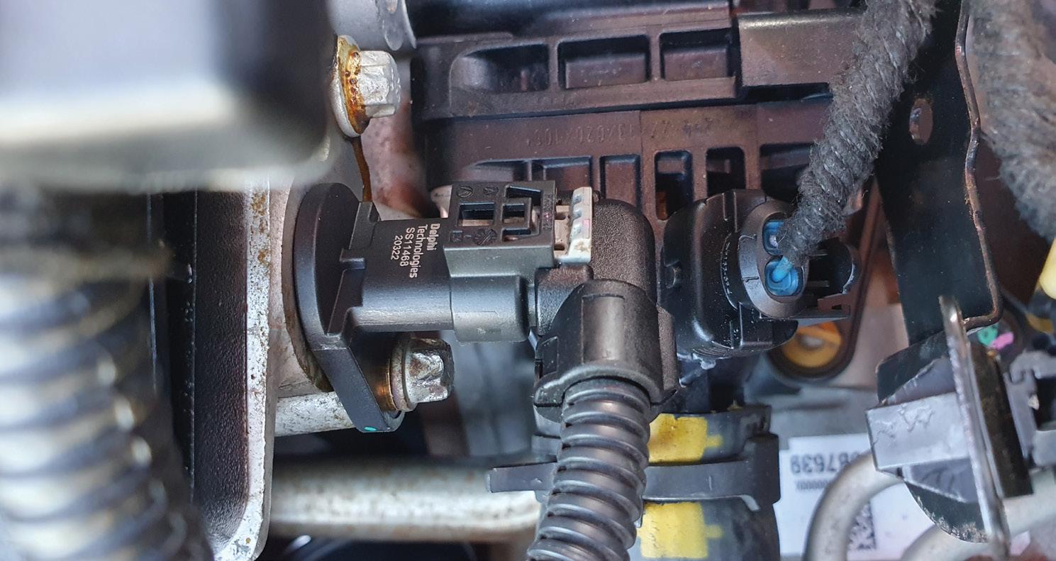
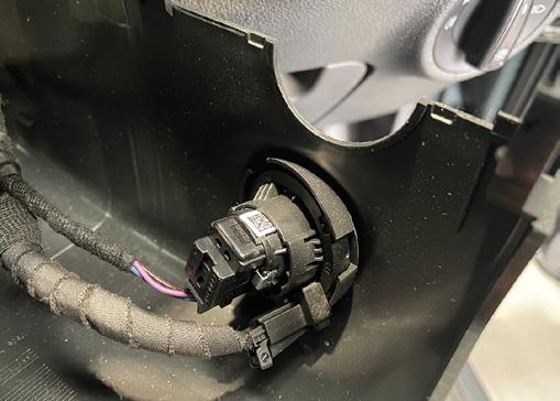
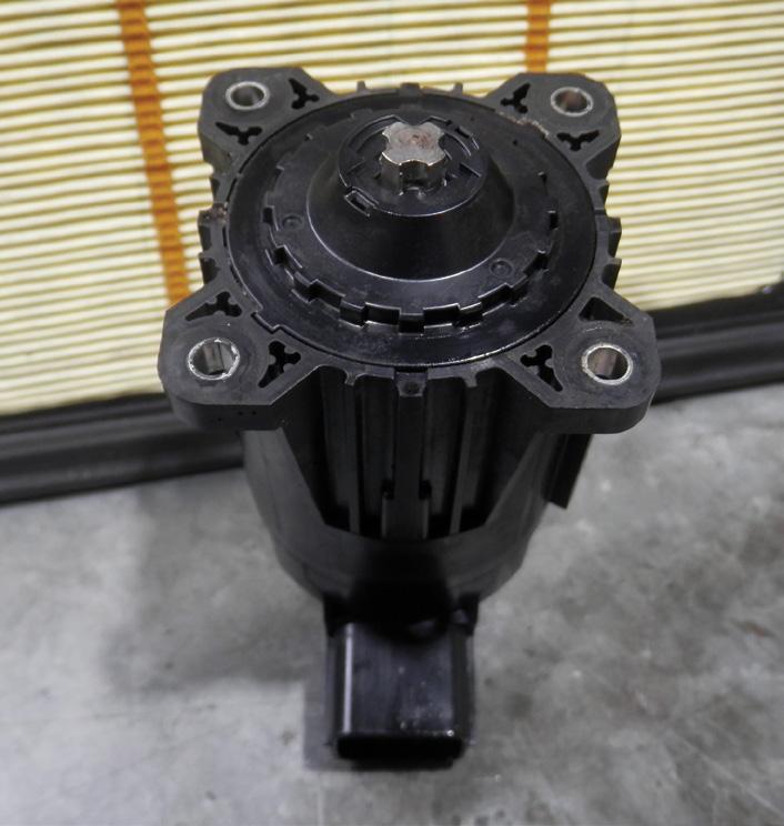
Fault description
The exhaust camshaft-position sensor was faulty, causing ECU problems (pic 1).
Unplugging the sensor allowed the engine to crank and start.
Fault solution
Installed a new exhaust camshaft position sensor (pic 2).
Recommended time
Diagnostic time was two hours, taking into account preparation and research.

The Test Run SBL function ensures the SBL can be loaded and executed. It’s essentially a quick, safe test that everything from your J2534 device to the file compatibility is good without actually erasing and attempting programming of the new calibration file.
The Test Run SBL was successful, so I then proceeded to carry out the programming function.


As is typical for Mazda, when programming commenced, the vehicle seemingly shut down, meaning the cluster and all interior lights went dead.
There’s no cause for panic. Just watch the percentage counter get to 100 per cent and hope it says, ‘Service procedure completed successfully’. Then think of your bank account increasing when the vehicle fires up correctly.
To confirm the process truly was successful, I confirmed I was now at software version C and no later version was available.
Fault description
PCM software calibration was required.
Fault solution
Updated the PCM software from PSHK189881-B to PSHK-18881-C.
Recommended time
Diagnostic time was 0.5 hours, taking into account preparation and research.
Repair time was 0.5 hours, taking into account the location of parts and carrying out the repair to a tested outcome.
Repair Solution by TaT Tech Team member Brendan Sorensen.

Customer complaint
The vehicle, powered by the 2.5-litre YD25DDTi turbodiesel four-cylinder and with 168,000km-odd on the clock, would crank but not start.
There was no communication with the scan tool. According to another mechanic, the vehicle needed a replacement ECM.
Problem summary
The ECM was given to me, already removed from the car. I offered to bench-test it to check whether it was capable of communicating or not. It did not look damaged.
Diagnostic sequence
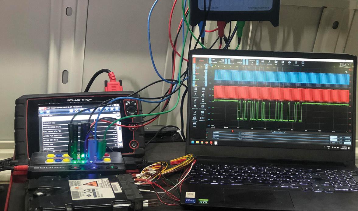
Checked the pinout for the ECM and used the GODIAG GT100 breakout box to provide powers, grounds, CAN and K-Line to the ECM.
Connected the Snap-on to the GT100 and was able to communicate via OBD and Nissan Enhanced (pic 1)
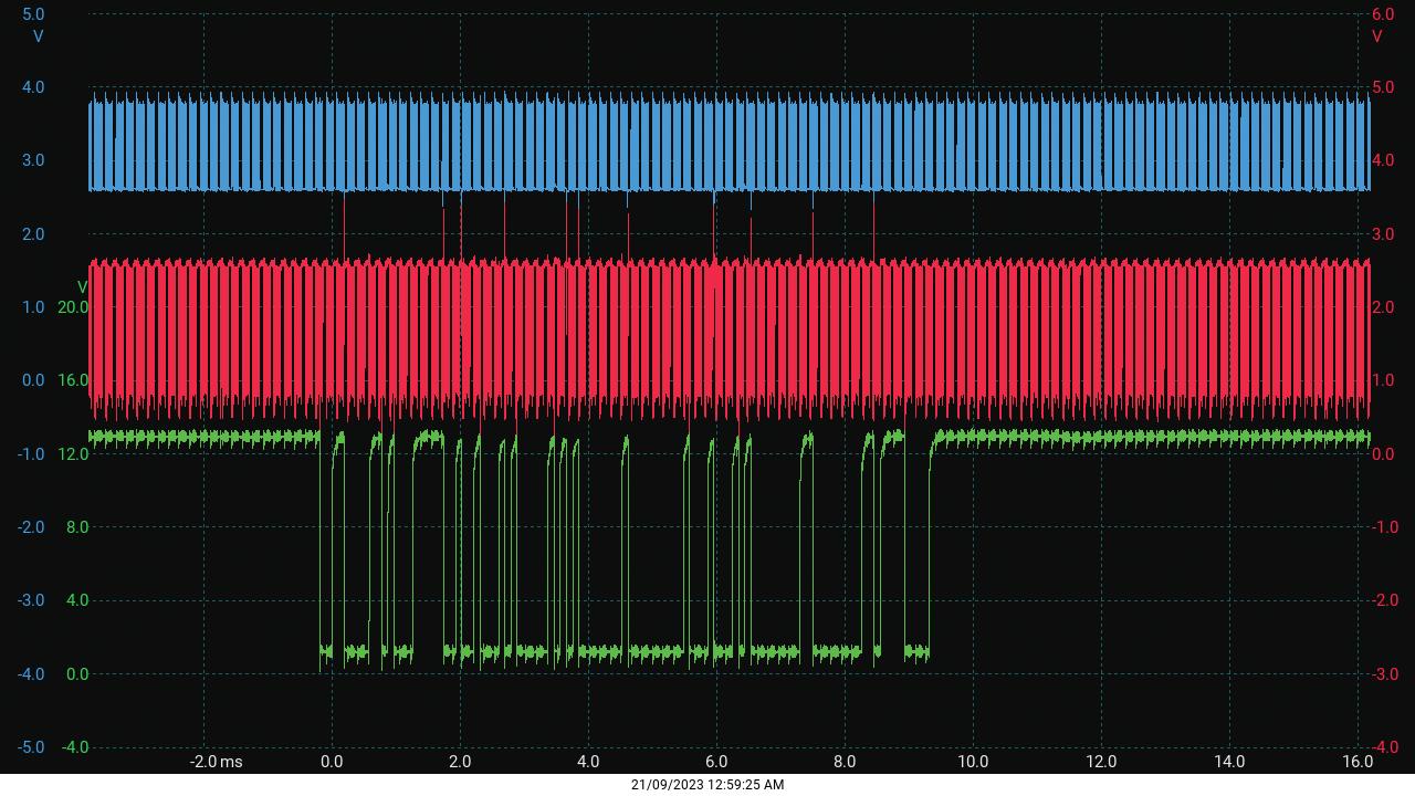
Checked for diagnostic trouble codes (DTCs) and monitored live data. Also checked the CAN and K-Line signals with the Pico to make sure they weren’t noisy or distorted.
All signals and communication were perfect (pic 2).
Refitted the ECM to the car and attempted to communicate but again there was no communication with the scan tool. The engine warning light was not on and the a/c thermo fan was constantly on, indicating there was no communication between the ECM and anything else.
Started again from scratch. Began by checking the battery –it was OK.
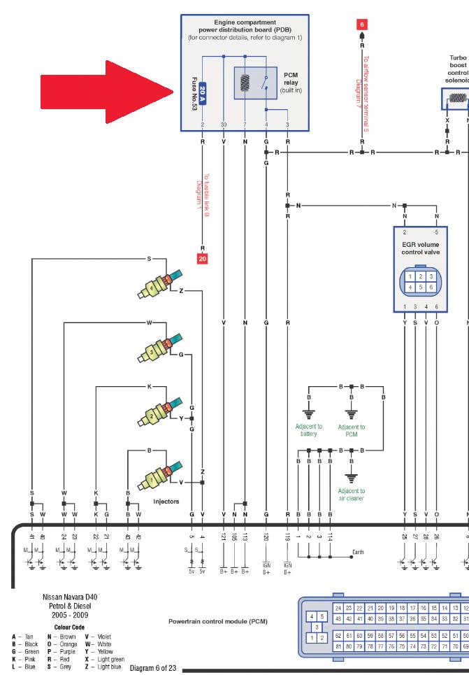
Checked the fuses and found one blown 20A fuse in the engine bay’s power-distribution board (PDB), in the left side of engine bay, fuse 53 (pic 3).
Fault description
There was no communication with the ECM, with the car cranking but not starting. It was caused by a blown fuse that provides power to the ECM.
I questioned the owner about how the fuse may have been blown. Apparently he and the previous mechanic were playing around with wiring trying to find a feed for an auxiliary of some sort and then the car wouldn’t start.
I suspect they spliced into the wrong wire or shorted something somewhere… then failed to retrace their steps.
Fault solution
Replaced the fuse and cleared the DTCs. The car now started, ran and drove normally.
Recommended time
Diagnostic time was 30 minutes, taking into account preparation and research.
Repair time was about 10 minutes, taking into account the location of parts and carrying out the repair to a tested outcome.
Always check the basics and try and get the full story from the customer!
TaT thanks Gary O’Riain (GO Diagnostics, Gulgong, NSW) for providing this case study via TaT Share, adapted for this Repair Solution.


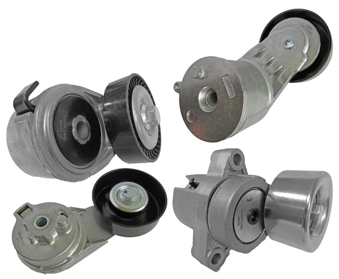
GMB’s belt-tensioner and idler-pulley program offers extensive coverage of the Australian car parc, with the brand’s current range covering more than 500 part numbers and new developments released every year.
Engines of today are quite different in terms of how belt-driven accessories such as the alternator, a/c compressor and hydraulic power-steering pump operate.
New components have been developed including multi-V grooved drive belts to provide additional grip with the pulleys, specialised belt tensioners designed to maintain a constant and optimal belt tension and additional idler pulleys to maximise belt wrap, further improving grip on each of the driven accessories.
Tensioners, belts, and idler pulleys are wear-and-tear components and need regular inspection.
Belts should be replaced if they have any cuts, cracks, missing pieces, fraying, uneven wear or contamination from oils or other fluids.
Tensioners and idlers should be replaced if they emit noise, exhibit excessive play or show rough bearing operation.
The bearings in the tensioners and idler pulleys must be smooth and quiet in operation. If there is any noticeable noise, they should be replaced.
GMB means precision engineering
At the heart of every GMB belt tensioner and idler pulley is a precision-engineered GMB bearing.
GMB is a Tier 1 OEM manufacturer and has been in business for more than 75 years.
GMB Premium OE-Quality Tensioners, Idler Pulleys and Timing Components are all manufactured to meet or exceed OE specifications and are produced in GMB plants under quality accreditation ISO/TS16949, ISO9001, ISO9002 and ISO14001. If the product is in a GMB box, it was 100 per cent manufactured within a GMB-accredited factory.
Based on advanced bearing technology and approximately 75 years of manufacturing experience, GMB tensioners and idler bearings have met the rigorous requirements of vehicle manufacturers, with GMB’s design concept based on the exact OEM part.
Functions of the tensioner and idler bearing
Belt-driven outer-ring mechanisms are inherent in this design. The tensioner bearing is positioned on the slack side of the beltdrive system, while the idler bearing is on the tight side. There are distinctive designs tailored to different engine configurations. Its primary functions include:
• Maintain consistent belt tension to ensure reliable accessory function.
• Transfer drive force efficiently from the crankshaft.
• Prevent belt slippage to maintain optimal performance.
• Reduce noise and vibration caused by misalignment or belt degradation.
• Optimise belt routing to enhance space efficiency in engine compartments.
Troubleshooting: Is it the belt, tensioner or idler pulley?
When an engine develops belt-related issues, the root cause is not always the belt itself. A failing belt tensioner or idler pulley can be the primary issue. Identifying the defective component ensures correct repairs and prevents repeated failures.
For example, a worn or failed belt tensioner can cause the belt to
become loose, leading to alternator undercharging, compromised a/c performance and power-steering malfunctions.
Simply replacing the belt may offer a temporary fix but if the tensioner is unable to maintain proper tension the issue will persist, resulting in premature belt wear and unnecessary customer comebacks.
It is crucial to check all related components and replace any faulty parts as multiple components often wear simultaneously. A misaligned belt due to a failing tensioner can also accelerate idlerpulley wear, further affecting system operation.
Ensuring all components in the belt drive-system are functioning correctly will enhance long-term reliability and performance.
• To find out more go to gmb-oceania.com

This 2018 Skoda Karoq with 54,234km on the odometer presented with an intermittent issue: the vehicle wouldn’t always start when the pushbutton start switch was pressed. Occasionally, it also wouldn’t turn off.
A fault scan revealed the following code: B11D729 – Ignition starter button, implausible signal. The key-fob battery tested fine but was replaced to rule out any doubts. Remote locking worked well at a distance, eliminating further suspicion of the fob.
Suspecting the start button, I removed it for inspection. The switch was easy to access and opening it revealed dirty
contacts on the pads. I cleaned the contacts and buttons with an electronic cleaner, reassembled the switch and refitted it.
After testing, the vehicle started and turned off reliably every time. Replacing the switch was considered but not pursued due to limited part availability.
Diagnostic time for this job was 30 minutes and repair time 30 minutes.
Winston Hannaway Winnie’s Auto Repair RONGOTAI, NEW ZEALAND
A 2018 Holden ZB Calais with 121,103km on the odometer came in with non-functional a/c and the check-engine light (CEL) on. The a/c button was lit but there was no cooling and the cooling fans were running.
Carried out a pre-scan and checked live data in the engine and heating, ventilation and a/c (HVAC) modules.
Logged into Holden’s service info to check for Technical Service Bulletins (TSBs) and information about a/c inhibit but didn’t find anything relevant.
A scan of the vehicle revealed the fault code, P0128:00 – Engine coolant temperature (ECT) below thermostat regulating temperature, with freeze-frame data showing 70ºC.
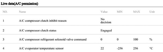
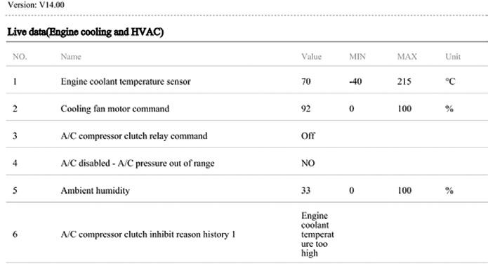
Checked the last a/c inhibit reason in the engine module, which showed ‘Engine coolant temperature too high’. However, there were no signs of overheating during stationary and road tests.
Instead, all signs pointed to a stuck-open thermostat causing the engine to run too cold. In the HVAC module, the a/c inhibit reason was ‘No decision’, with zero per cent command to the solenoid valve.
The P0128:00 fault was the reason the a/c was disabled. Cleared the fault code and the a/c instantly became functional, confirming the issue.
Removed the intake plenum to access the thermostat housing. Replaced the thermostat and retested – coolant
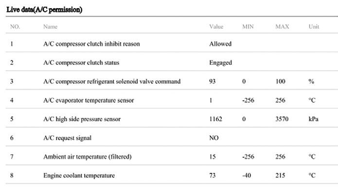
temperature was now regulating between 90-95°C and the a/c was fully operational. Diagnostic time for this job was two hours and repair time was three hours.
Matthew Nagel Warragul Automotive DROUIN, VIC


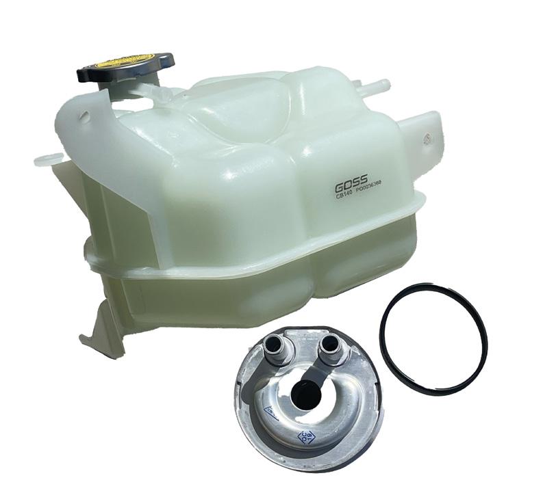
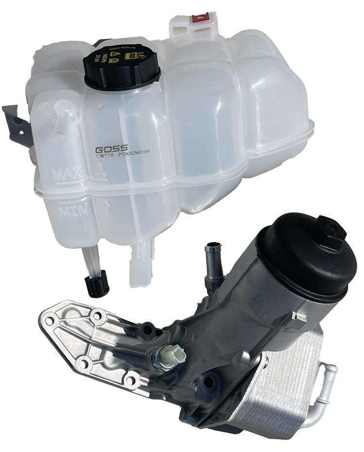
Goss Cooling System Kits (CSKs) are designed to deliver a ‘do it once, do it right’ solution for cooling-system repairs.
Each CSK includes a Goss Engine Oil Cooler and Goss Coolant Bottle, ensuring both crucial components are replaced together for maximum efficiency and longevity.
Some applications, including the Holden Cruze, Trax 1.8-litre and Barina 1.6-litre, also include associated coolant pipes, providing a comprehensive, hassle-free solution.
Sourced from world-leading original equipment suppliers (OESs), Goss Engine Oil Coolers are designed to meet or exceed factory specifications, ensuring perfect fitment and optimal performance.
Each oil-cooler kit includes fitment gaskets where necessary, while Goss Coolant Bottles come with a cap and level sensor where applicable.
The Goss CSK range launches with 13 carefully curated kits covering more than 1.2 million of the most common vehicles on Australian roads, offering workshops a convenient, high-quality repair solution.
Why replace both?
Replacing only the oil cooler or coolant bottle increases the risk of cross-contamination.
A failing oil cooler can mix engine oil with coolant, forming a sludge that clogs the radiator, heater core and coolant passages –potentially leading to overheating and severe engine damage.
Even after a thorough system flush, residual contaminants in an old, weakened coolant bottle can reintroduce sludge, causing repeat failures.
Proactive replacement is more cost-effective than repeated repairs. Multiple flushes and additional labour can quickly exceed the cost of replacing both components at once.
Installing a Goss Cooling System Kit is a way to provide a long-term, reliable repair, saving time and money while ensuring optimal vehicle performance.
With more than 80 years in the automotive aftermarket, Goss is known for quality, reliability and innovation.
Goss products, sourced from world-leading manufacturers, are designed to meet rigorous OEM standards and with workshops in mind. They’re engineered to save time, reduce comebacks and ensure customer satisfaction.
Choose Goss for trusted quality, superior fitment and industry-leading support.
• Find out more about Goss CSKs at goss.com.au

Diesel particulate filters (DPFs) perform an important function in modern diesel-powered cars.
These devices capture and store exhaust soot and ash in a honeycomb-shaped substrate made from a special ceramic material. Those particulates are then burned off as the filter regenerates. However, when a DPF does not reach the temperature required to burn off the soot trapped inside the filter, these particulates build up and eventually prevent the DPF from working properly. What follows is a loss of performance, lack of power and torque and harmful pollutants being released into the atmosphere – and, quite often, the cabin.
In the most severe cases, a DPF needs to be replaced or removed and professionally cleaned in a high-temperature, highpressure DPF-cleaning machine. However, if diagnosed early, a blocked DPF can be successfully treated without removing it from the vehicle.
The common signs of a blocked DPF are increased fuel and oil consumption, poor engine performance, reduced turbo performance, increased idle speed and finally a check-engine light (CEL) or DPF warning light.
The easiest way to diagnose the severity of a DPF blockage is by using a back-pressure test tool such as the JLM Manometer. This compact, digital instrument is one of the most useful diagnostic tools in an automotive professional’s arsenal and can be used to check any automotive pressure sensor.
On-car solutions for small blockages
For blockages up to 30 millibar (mbar), use JLM Diesel DPF Cleaner. This solution is effective at targeted and preventative cleaning of the entire exhaust path of diesel engines with a particulate filter.

As well as cleaning the soot filter, it’s also formulated to reduce air-polluting particulate matter, hydrocarbons, carbon monoxide and soot emissions. To use, simply pour JLM Diesel DPF Cleaner into the diesel fuel tank.
If the blockage is at or slightly over 30mbar, step up to JLM Diesel DPF Cleaner Heavy Duty. This solution contains a higher concentration of active additives and is recommended for trucks and commercial fleets.
JLM DPF Cleaner Heavy Duty is also formulated to condition the engine and DPF, resulting in better performance and lower fuel consumption. Add to the diesel fuel tank after refilling.
On-car solutions for medium blockages
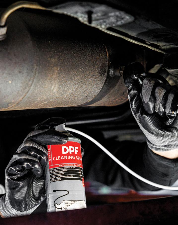
DPFs with blockages up to 80mbar can fail official emissions tests. JLM Diesel DPF Spray comes in a handy aerosol can and contains a high concentration of active ingredients. It’s formulated to clean and regenerate dirty and blocked DPFs by reducing the combustion temperature of particulate, making it combust earlier and faster at a lower engine temperature.
To use, simply spray JLM Diesel DPF Spray into the DPF prior to forced regeneration – by means of a test drive or on-board diagnostics – to clean the filter.
On-car solutions for heavy blockages
When encountered with a blockage of over 80mbar, you need to reach for the big guns.
The JLM Diesel DPF Cleaning Toolkit is designed to be the most potent on-car DPF cleaning option available to workshops.
In combination with the JLM Diesel DPF Cleaning & Flush Fluid Pack, it employs a two-step method of loosening and then removing the soot trapped in the ceramic filter.
The first fluid is a strong pre-soaking cleaner that pre-treats and loosens the soot and
grease. After loosening the particulate matter, the flush or rinsing fluid flushes the filter until it is thoroughly clean.
This disperses ash from the soot particles throughout the DPF, pulling them apart from each other. The soot is then effectively burnt off during the forced regeneration.
To prevent a DPF from becoming blocked, use a DPF additive such as JLM Diesel DPF ReGen Plus.
This solution is formulated to support the regeneration process, resulting in a more complete oxidation of soot and an overall improvement of DPF performance.
The high concentration of active ingredients in DPF ReGen Plus ensures soot in the filter burns at a lower temperature and therefore sooner and better. It is particularly suitable for commercial vehicles or passenger cars that primarily make short journeys or frequently operate at low speeds.
• Netherlands-based JLM Lubricants is one of Europe’s leading manufacturers of fuel additives. To find out more, call JLM Lubricants Australia on 02 9133 3855 or go to jlmlubricants.com.au
This is part two of a case involving a troublesome 2016 Mitsubishi Triton with 144,000km on the clock.
The vehicle had presented with the checkengine light (CEL) on. This was expected – a diagnostic test for intermittent running issues had involved fitting an exhaust-gas recirculation (EGR) blanking plate and longer drive cycles with it fitted had likely triggered a suspected EGR fault.
A scan revealed the fault code, P0401 –Exhaust gas recirculation flow insufficient.
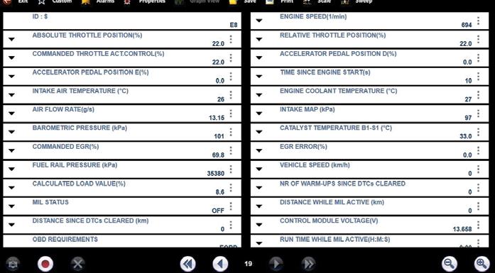
Using a Snap-on Verus Edge scan tool, we measured basic parameter IDs (PIDs)
in OBD at idle, focusing on mass air flow (MAF) readings.
With the blanking plate installed, MAF was 13.15 grams per second (g/s). Removing the blanking plate caused the engine to idle poorly and MAF dropped to 7.9g/s. Further testing confirmed significant exhaust-gas flow from the EGR-tointake manifold pipe at idle, pointing to a mechanical issue with the EGR valve.
The fault was traced to a stuck-open EGR poppet valve due to a mechanical failure –not an electrical issue.
Removed the EGR-valve assembly and separated the electric motor section. Depressed the poppet-valve return spring collets and cleaned the valve using a wire buff.
After reassembling and refitting the EGR valve in its original condition (with no blanking plates), the vehicle ran fine with improved performance.
A final check showed the MAF reading at idle with a working EGR was now 14.9g/s.
Diagnostic time for this job was one hour and repair time three hours.
Gary Homan Nudgee Automotive Services NORTHGATE, QLD

The update from Euro 5 to Euro 6 diesel emissions controls represents a significant change in automotive emissions regulations, pushing manufacturers to develop innovative solutions.
Heavy and light vehicles have different implementation schedules and standards. Diesel cars, utes and light commercials
Announced in 2023, the Federal Government requires all new cars, SUVs and light-commercial vehicles introduced to Australia from December 2025 to meet Euro 6d standards. Existing models introduced prior to that date will have until sometime in 2028 to meet the strict emissions standards.
Australia introduced Euro 5 in 2016. Euro 5 established fundamental requirements, while Euro 6 – from Nov 2024 for existing models and Dec 2025 for new models – brings substantial enhancements.
Euro 5 emissions standards for diesel cars
• Carbon monoxide: 0.50g/km
• Hydrocarbons + nitrogen oxides (NOx): 0.23g/km
• Nitrogen oxides: 0.18g/km
• Particulate matter: 0.005g/km
• Particulate number: 6.0×10 ^11/km
Euro 6 emissions standards for diesel cars
• Carbon monoxide: 0.50g/km
• Hydrocarbons + nitrogen oxides: 0.17g/km
• Nitrogen oxides: 0.08g/km
• Particulate matter: 0.005g/km
• Particulate number: 6.0×10 ^11/km
The key difference lies in the NOx emissions reduction from 18g/km to 8g/ km, requiring significant engineering changes.
Two technologies for Euro 6 Selective catalytic reduction (SCR) uses Adblue to convert NOx into harmless oxygen and nitrogen. This is the most common NOx-reduction system. Alternatively, dual exhaust-gas recirculation (EGR) systems combine
parallel high and low-pressure EGR circuits to more efficiently reduce production of NOx at different temperatures and engine loads. It’s usually used instead of AdBlue (i.e. Euro 6 Subaru diesels) but sometimes used with Adblue (i.e. certain Range Rovers).
DPF Australia has a good understanding of current emissions requirements which, along with its X-ray spectrometer and other test equipment, allows it to ensure its DPFs and SCR systems meet correct emissions requirements, giving repairers confidence in its products’ ability to meet emissions standards.
The DPF Australia team is ready to assist with technical advice and diagnosing possible underlying issues.
• To find out more call DPF Australia on 1300 821 877, email enquiries@dpfsales.com.au or go to dpfaustralia.com.au

The TaT Technical Assistance page is a vital resource for members facing difficult diagnostic or repair challenges in their workshops.
Whether an unusual fault is stumping you, you need guidance on how to approach a tricky repair or simply have a general automotive-related question, this service connects you to a wealth of expertise – both human and AI-powered.
How it works
At the core of this service is the Technical Assistance form, designed to capture all the critical details of the vehicle and its problems. Once the form has been submitted, processed and set live, the first responder to your help request will be Tech Tony, the AI-powered assistant from the TaT Technical Team, followed closely by any Technical Team or TaT members who may have information to assist you with your problem.
Why Tech Tony is your new best friend for diagnostics
Think of Tech Tony as your super-smart workshop buddy who never forgets a repair trick.
Tech Tony is an AI-powered assistant developed to assist TaT members who have submitted a Technical Assistance help request. He is the brother of Tech Tina, our other AI team member who assists with general or technical automotive questions. Tony focuses on providing members with accurate, guided technical assistance and will quickly analyse your issue and provide suggestions based on a vast database of successfully resolved cases, known as Repair Solutions. However, for Tech Tony, the Technical Team and TaT members to deliver the best possible results, you must provide as much detail as possible when filling out the assistance form.

common mistakes when filling out assistance forms
When submitting a Technical Assistance request, it’s important to provide comprehensive information to ensure the best support. Here are some key points to remember when completing the form:
• Vehicle-specific or non-specific
This is the first choice you need to make and probably the most important. Selecting nonspecific will give you a basic form, which is great if you are in a hurry and have a basic general question. However, if your question has absolutely anything to do with a specific vehicle, you should not be selecting this option. The result of selecting non-specific will be that you will not provide enough information for anyone to assist you properly. So if you are asking for help with a vehicle, make sure you select the vehicle-specific option.
• Vehicle details
Include the make, model, year, engine type, transmission and other relevant vehicle specifications.
• Symptom description
Please describe the problem with as much detail as possible, including when it occurs (e.g. only when the weather is cold or only while accelerating, etc.) and any specific circumstances that might affect the issue.
• Fault codes
If you have already scanned the vehicle, include any fault codes along with the code descriptions and list any permanent fault codes remaining after clearing all systems.
• Test results
Provide details of any tests or diagnostics steps you have already performed (e.g. voltage readings, oscilloscope captures, etc).
• Previous repairs
If any parts have been replaced or repairs performed, be sure to also mention those. Remember, the more context and specifics you provide, the more effectively Tech Tony, the Technical Team and TaT members can assist you.
Why filling in every detail matters
Leaving out details in your Technical Assistance request might delay your solution or result in less accurate advice.
When Tech Tony and the TaT team have a complete picture of the problem, they can offer more tailored and effective recommendations. Plus, when you provide


the final fix it helps everyone, ensuring the issue is added to the Repair Solutions database so the next technician can benefit from your experience.
While our team does its best to assist members with any information requests, TaT is not a data provider. We are not allowed to share any copyrighted material from manufacturer information or aftermarket-data providers. This means we cannot provide wiring diagrams, pinouts, belt layouts or any other diagrams or images. For factoryspecific diagrams and layouts, our OE Info Resource is your go-to guide to accessing manufacturer portals.
Once you have received assistance and found a fix for the vehicle, you must return to the website and close off the case with a description of the fault and how you repaired it. When a member closes an assistance case correctly, providing information about the fault and fix, this information can be reviewed by the TaT team and, if suitable, converted into a Repair Solution, which is then stored in the searchable database that may be useful for members in the future with similar problems.
So, the next time you are in a bind with a difficult vehicle issue, don’t hesitate to visit the TaT Technical Assistance page and let Tech Tony and the TaT team help you with that repair. Remember to close the case and share the fix when the issue is resolved to help others and strengthen the TaT community.
Visit the TaT Technical Assistance page now and see how much time, effort and frustration you can save.

In our previous two articles in this series we’ve attempted to use our existing mechanic’s underpinning knowledge as a peg to demonstrate:
1. How petrochemical energy, released in an internal combustion engine (ICE) and measured in joules, can be used as a common thread with that of the electrical energy used in hybrid and/or full electric vehicles (FEVs), which is also measured in joules – equating to one watt of electrical power being used for one second (often referred to as a wattsecond – see part 1, TaT issue 102).
2. A hypothetical FEV internal cabin-heater element (rated at 1kW) was considered as part of the heating, ventilation and air-conditioning (HVAC) system. The amount of current drawn (in amps) from a 12.8V conventional battery was compared to that of the current drawn from a 400V supply, illustrating the advantages of using high voltage (see part 2, TaT issue 103).
Which brings us to where we left off, with a minor modification (pic 1) where the HVAC heating element has now been replaced with a three-phase traction AC motor that propels the vehicle (via a DC-to-AC inverter), rated at 1kW.
Please note that unlike the heating element (which is rated at 1kW and represents the amount of electrical power consumed by the element), the AC motor (which is also rated at 1kW) is measured by the mechanical power it produces – 1kW of electrical power equals 1.34 horsepower (hp). More on that later.


In this article, we will attempt to explore:
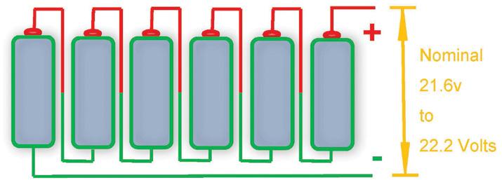
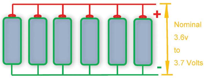
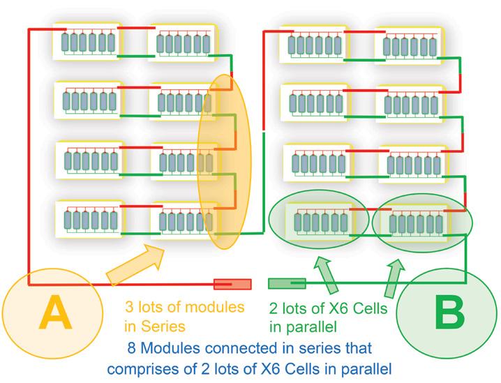
• How such high current/voltage ratings are achieved with batteries (of nominal 3.65V and three amp-hour [Ah] capacity) simply by configuring them in series and parallel (pic 6A-B and pic 7).
• Why engineers have opted for lithiumion batteries instead of conventional lead-acid batteries.
• And above all, who keeps an eye on the welfare of these batteries – could it be the BMS?
For that, we will begin by referring to available engineering literature.
Again, without getting involved in academic discussions, the following is a simplified dissertation put forward from a mechanic’s point of view (MPOV).
1
Let’s begin by reviewing the essential voltage and current supply requirements used by manufacturers for modern FEVs.
Prelude
FEVs have placed continuous demands on engineering design teams to not only meet but exceed driver expectations regarding exhilarating driving feel and performance. This has led engineers to push new and sometimes near-impossible boundaries, designing batteries that meet the electrical requirements of modern FEVs.
While much is documented regarding the different battery types used by manufacturers to meet required specifications (often dictated by the efficiency of an FEV), we will limit our

3
4
discussion to the following power requirements (based on available manufacturer literature):
• Voltage: Ranging between 250V and 500V.
• Power rating: To cater to electric motors with outputs between 50-200kW.
• Capacity: Measured in kilowatt-hours (kWh), allowing the vehicle to travel 200km to 600km on a full charge (ref 1).
This brings us back to our initial dilemma –can the durability of lead-acid batteries be used as a power source for EVs? If not, why have engineers opted for different variations of lithium-ion batteries?
Lithium-ion or lead-acid batteries?
The required DC supply voltage for modern passenger FEVs typically varies from 250V to 500V.
But there are exceptions. Some highperformance FEVs may use voltages as high as 800V.
So why are lithium-ion batteries (or variations thereof) favoured over traditional lead-acid batteries, including heavy-duty deep-cycle batteries?
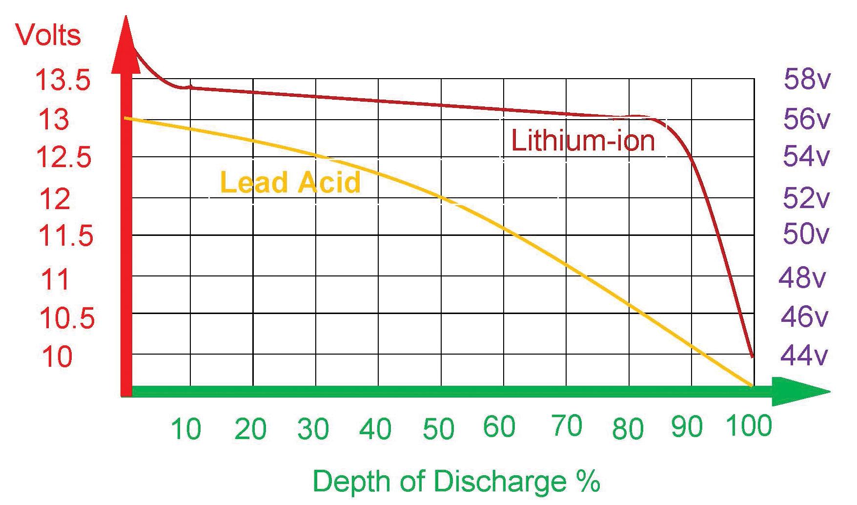
Available engineering literature (ref 2 and 3) illustrates that lithium-ion batteries have unique charge-discharge characteristics.
While regenerative braking accelerates the charging process when the vehicle is in motion (more on that later), it is the discharge characteristic that attracts the most attention from engineers (pic 2).
As seen in pic 2, where the graph represents depth of discharge (DoD – X-axis, green) and state of charge (SoC – Y-axis, red or purple), it becomes evident that lithiumion batteries (brown curve) have a flatter discharge curve than lead-acid batteries (yellow curve).
From an MPOV, this means the lithium-ion battery holds its charge longer before it takes the plunge.
Regardless of whether the battery block – which consists of multiple modules – is
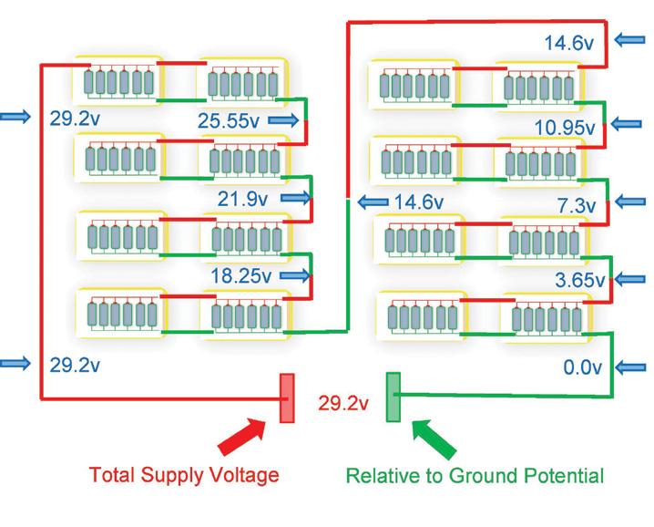
rated at 12.6V (left, red Y-axis) or 56V (right, purple Y-axis), they both exhibit the same discharge-curve characteristics (ref 2 and 3).
Now assuming each individual lithium-ion battery has an average nominal open-circuit voltage of 3.65V, how are these batteries configured to yield not only high voltages of 250V to 500V but high current ratings ranging from 50 to 250Ah?
Battery configuration (6S and 6P)
Most manufacturers utilise their own unique battery-module configurations, which may vary between models.
However, in simple terms, the configuration of individual lithium-ion cells – whether placed in series or parallel – determines the voltage, current capacity and kWh rating.
For example, let’s hypothetically assume we have a single lithium-ion battery cell with:
• A nominal voltage between 3.6V and 3.7V.
• A capacity of 3.0Ah (pic 3).
If six of these batteries are placed in series (pic 4), forming a module, the total nominal voltage of the combination will be between 21.6V and 22.2V.
This arrangement is commonly referred to as ‘6S’ – since it has six cells in series.
While this set-up increases voltage, the current capacity remains limited to 3.0Ah (for one hour).
To increase the current rating, manufacturers connect batteries in parallel (pic 5).
This arrangement is known as ‘6P’, meaning six cells in parallel. This boosts capacity sixfold to 18.0Ah (for one hour) but the nominal voltage remains between 3.6V and 3.7V (average 3.65V).
Battery-management system (BMS)
As seen in pic 8, the complex network of series and parallel battery connections creates a highly intricate system. While extremely organised, it requires precise monitoring of individual battery-cell
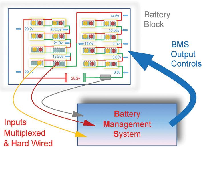
performance, behaviour and operation (pic 8 – grey, brown, yellow).
If the battery block malfunctions, the BMS not only alerts the driver via a message on the binnacle display and warning chimes but electronically intervenes in the vehicle’s performance (pic 8 – blue output arrow). So is it possible the BMS is yet another electronic control module, similar to, say, a powertrain control module (PCM) or body control module (BCM)? And from the MPOV, does it monitor its inputs and, based on internal algorithms and a preprogrammed ‘flow chart’, execute the required external interventions (see TaT issue 73, pages 6 and 7)?
If you think so, and we’ll delve deeper in our next publication, would you be able to predict what the grey, brown and yellow sensors in pic 8 are and what their purposes are?
1. ev-database.org/cheatsheet/rangeelectric-car
2. batterypowertips.com/how-to-readbattery-discharge-curves-faq/
3. thepilotgroup.co.uk/lithium-ion-batteryvs-lead-acid-battery/
Please note, the purpose of these articles is to illustrate the why and how, bolstered with some basic theories, of EVs. However, readers should be warned that contact with high voltages is potentially lethal. If you wish to measure high voltages, all safety measures and precautions must be observed such as using CAT IV DMM gloves and so forth. To prevent injuries, this should only be attempted after completing industrystandard de-powering procedures training.
• Want to learn more about hybrid and EV batteries? Visit the Technical Training tile on the TaT homepage to view TaT’s HV Battery SOH on-demand webinar now.

Jason Smith
The vehicle
Mitsubishi Triton MR, 09/2019, 4N15 2.4-litre diesel engine, 60,881km on the clock (pic 1).
The complaint
The diesel particulate filter (DPF) warning light was on.
Diagnostic sequence
Noticed a slight lack of power while road-testing the vehicle, so returned the vehicle to the workshop to perform numerous basic tests and checks, including checking all lights and fluid levels. Found the engine oil level was over full – noted it on the job card and continued.

While visually and physically checking the under-bonnet hoses and fittings, found the main air-intake hose between the intercooler and throttle-body was split from underneath (pic 2).
This was no surprise because it’s common to see this problem with Tritons and Pajeros with 4N15 engines, so the smoke machine hadn’t made it out of the cupboard yet. However, the real surprise was the split intake hose was the same age as the car, meaning it had only travelled 60,000km. Continuing the inspection, I smart-tested battery and charging system before performing a full diagnostic scan of all modules.
I found no DTCs in the engine computer. Next, ran the engine while closely examining all data parameter IDs (PIDs), especially the three exhaust-temperature sensors (I’ll explain later why close attention was paid to the exhaust-temperature sensors).
dilemma
This is normally where the problem would be simply fixed by ordering and fitting a new air-intake hose, correcting the engine oil-level issue and clearing any DTCs before
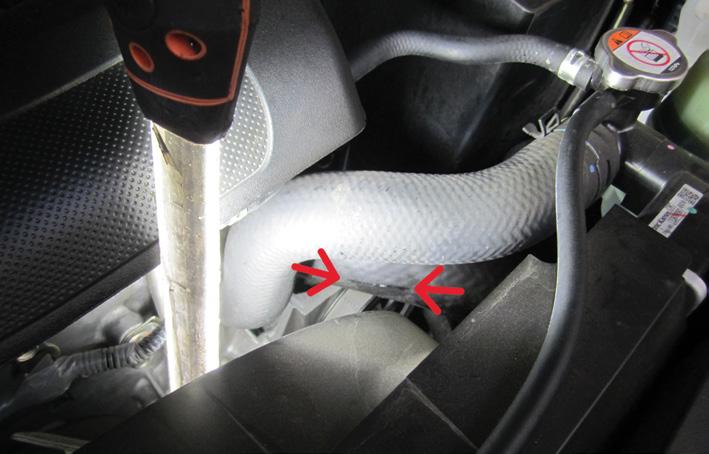
sending the car out the door.
However, in simple terms, in this case the oil level being too high actually meant oil dilution with fuel, which is caused by the vehicle not being able to complete DPF burns (i.e. passive regenerations).
That excess fuel added for DPF burns bypasses the engine rings and ends up in the engine oil, thereby diluting it, greatly diminishing the oil’s lubrication characteristics.
This is where the plot really thickens. 4N15 engines are known for intermittent issues with the #3 exhaust-temperature sensor going open circuit, meaning the temperature-specification criteria for the system to complete a DPF burn will not be met.
Normally, if the #3 exhaust-temperature sensor faults, no DTC is logged. I had run the engine with the data PIDs for all three exhaust-temperature sensors in the system displayed and carefully manipulated the wiring harnesses, especially on the #3 sensor – no dropouts or abnormal readings were evident, both static in the workshop or on road tests.
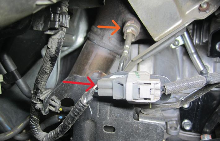
The #3 exhaust-temperature sensor is located on the right side of the engine bay at the rear of the DPF. The wiring harness and connector are close by (pic 3: orange arrow – sensor, red arrow – wiring connector). The sensor and harness can be accessed via the right-front inside wheelarch.
I discussed my findings on the split intake hose, the #3 exhaust-temperature sensor’s intermittent fault and the oil dilution with the owner.
Ordered and installed a new main air-intake hose, then hooked up the smoke machine to the intake system to check for no further leaks – all was OK.
Changed the engine oil and oil filter and reset the oil-dilution calculation data within the engine computer using the scan tool. Like a small injector-quantity relearn, it’s very important to perform the oil-dilution value reset on Mitsubishi diesel vehicles.
Next, I road-tested the vehicle, experiencing no further problems.
Unfortunately, the customer did not want to replace the #3 exhaust-temperature sensor as a precaution. In all fairness, it’s not a

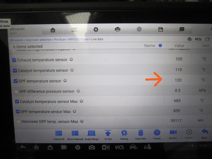
cheap exercise and at that stage I had no solid evidence to indicate there were any additional problems.
The vehicle was returned to the owner with a request to return it in 1000km to recheck the oil level, along with a firm warning that the vehicle may still have another problem in not allowing DPF burns to be completed. The vehicle was returned a few weeks later as requested. Unfortunately, the engine oil had continued to rise approximately 10mm above the full mark (pic 4), so corrected it by using a suction device through the dipstick hole.
Returned the vehicle to the owner with another request to recheck again. A few weeks later the vehicle came back and as expected, the oil level had risen again and was now approximately 10mm higher than the full mark.
I told owner the car would need further diagnostics and possibly replacement of the #3 exhaust temperature sensor as a precaution, and a few weeks later it was returned for further inspection.
Once again, diagnostics was firmly aimed towards all three exhaust-temperature sensors. Data was displayed and wiring looms and connectors were firmly manipulated – there were no dropouts or obvious problems to be found (pic 5).
Note that I unplugged the #3 exhausttemperature sensor (pic 6) – you can see the data reads approximately 20ºC but no DTC is logged, which is what you would expect to see during a fault event.
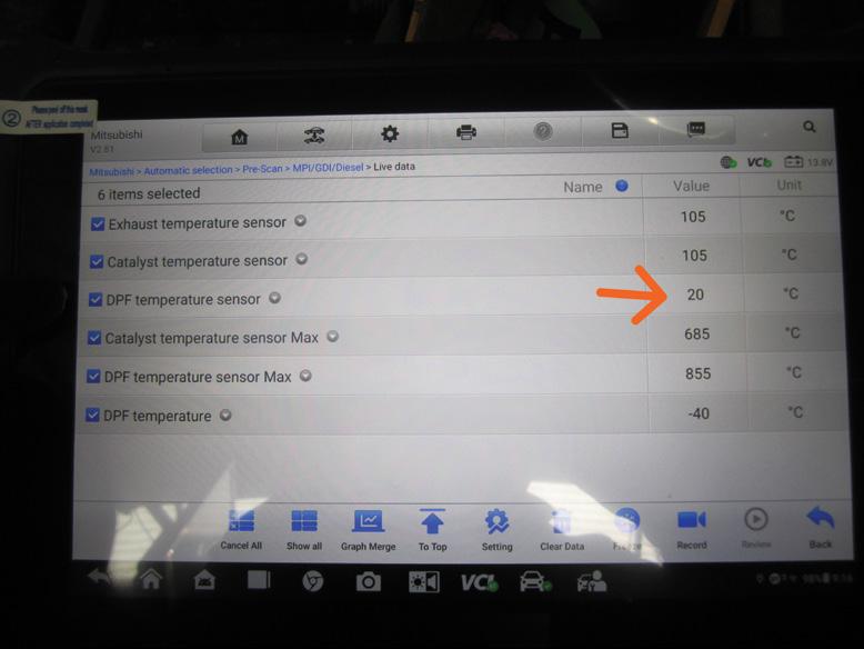
The owner finally made the decision to replace the #3 exhaust-temperature sensor as a precaution.
Normally as highly skilled technicians, we base decisions on the evidence before us. Most of the time this will be scan or scopedata readings or even an obviously broken part.
However, sometimes we need to replace a component based on a knowledge-based decision – this is fine as long as the owner is kept in the loop.
It’s sometimes uneconomical to spend hours and hours on the diagnosis of an intermittent fault that won’t rear its head when a known fault may be staring you right in the face. This is fine as long as the owner is kept completely in the loop and ultimately makes the final decision (and financial commitment).
In this case, I ordered and installed a replacement for the suspect #3 exhausttemperature sensor, replaced the engine oil and reset the oil-dilution value using the scan tool.
Next, I checked the DPF pressures using a manometer – they were OK – before roadtesting it while monitoring certain data PIDs –all of those readings also appeared to be OK. I returned the vehicle to the owner with some questions about her driving style and the routes she covered, recommending longer trips and encouraging her to drive in a more spirited manner. I also requested the vehicle be returned again to recheck the oil level.
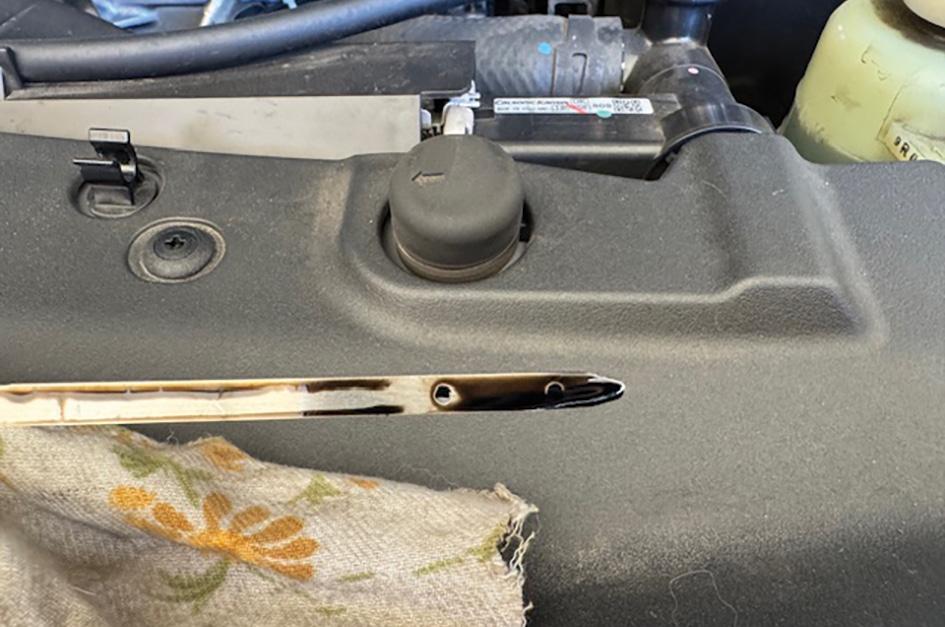
The vehicle was returned numerous times over the next few weeks and each time the oil level was checked and found to be correct (pic 7), confirming a fix and resolution to the problem.
I’ve adopted a strategy when any Mitsubishi Triton or Pajero with the 4N15 engine comes in for service. It will have all of the air-intake pipes thoroughly checked and a recommendation to replace the one in the above case study as routine maintenance every 60,000km. The #3 exhausttemperature sensor will also have its wiring and data readings checked and a caution alerting to possible intermittent faults.
This vehicle ended up a good outcome. I will point out there was a lot of communication with the owner about the problem. I’m suspecting some customers don’t want to return their car for checks or inspections, but it’s all a part of coming to a complete resolution to a problem.
Yes, if the #3 exhaust temperature sensor had been replaced the first time, then numerous return visits may not have been required. However, this was the owner’s decision and it should always be the owner’s decision.
That’s why communication is key with your customer – you need to be on the same page moving forward, so you’re not made out to look like a dill.
Happy diagnosing!

The Australian Automotive Aftermarket Association (AAAA) has congratulated its sister organisation, the Auto Care Association and President and CEO Bill Hanvey, on its landmark victory in Massachusetts in the United States.
This ruling upheld the 2020 Right to Repair law, requiring automakers to provide independent repairers with access to telematics data – an important step forward for consumer choice and fair competition in automotive repair.
AAAA CEO Stuart Charity said the decision highlighted the need for urgent reform in Australia, where the Motor Vehicle Information Scheme (MVIS) provided world-leading access to service and repair data but excluded telematics.
‘Australia has the best Right to Repair legislation in the world and the Federal Government deserves credit for this landmark reform,’ said Charity. ‘However, technology has rapidly evolved and our law must keep pace.
‘Modern vehicles rely on telematics to diagnose and repair faults, yet independent repairers in Australia are locked out of this crucial data. The Massachusetts ruling confirms that telematics access is both legally viable and essential for a fair repair industry.
‘If we don’t act now, Australian consumers and independent workshops will be left behind.’
Technology in the automotive sector is advancing at an unprecedented rate. Increasingly, vehicles now receive wireless software updates that impact how key systems operate, meaning repairers need real-time access to vehicle data.
New safety features – including autonomous

emergency braking, lane-keeping assistance and adaptive cruise control – require dynamic calibration and updates to function correctly. These technologies can save lives and it is vital that independent repairers have access to the information to service and maintain these systems for the life of the vehicle.
Unlike the US, updating Australian law does not require new legislation. A straightforward amendment to the MVIS Scheme Rules could close the telematics gap.
For this reason, the AAAA is calling on the Federal Government to act now and ensure independent workshops have fair access to repair data for today’s highly connected vehicles.
Charity said the changes required to modernise Australia’s Right to Repair law were minimal yet the impact on the industry would be enormous. He said Australia had led the world in securing fair access to vehicle data and must continue leading, ensuring the MVIS remains fit for purpose.
Charity said the AAAA remained committed to ensuring Australia remained a global leader in Right to Repair and looked forward to working collaboratively with the government and industry stakeholders to bring this legislation up to date.
‘We stand ready to assist in this reform process and have written to Minister Andrew Leigh to begin this critical dialogue,’ said Charity. ‘Now is the time to future-proof our law and ensure Australian consumers
continue to have genuine choice in vehicle servicing and repair.’
The history of right to repair in Massachusetts
The fight for Right to Repair in Massachusetts has been ongoing for more than a decade. In 2012, it became the first US state to pass a Right to Repair law, requiring automakers to provide independent repairers with access to the same diagnostic and repair information available to dealerships. This led to a national agreement, ensuring fair access to vehicle data across the US.
However, as vehicles became increasingly connected, automakers began using telematics to transmit real-time data directly to their servers – bypassing traditional diagnostic tools and limiting access for independent repairers. In response, Massachusetts voters overwhelmingly approved a 2020 ballot initiative (by 75 per cent) to expand Right to Repair laws to include telematics. Automakers challenged the law in court, delaying its implementation for years.
Now with the court ruling upholding the law, Massachusetts has set a global precedent for telematics access.
The history of right to repair in Australia
The AAAA has been the driving force behind Australia’s world-leading Right to Repair law. The Motor Vehicle Information Scheme (MVIS), which took effect in 2022, mandates vehicle manufacturers provide independent repairers with service and repair data on fair and reasonable terms. This was a landmark achievement, ensuring Australian consumers had a genuine choice when it came to servicing and repairing their vehicles.
However, one crucial gap remains – telematics data is not covered. Telematics systems, which transmit real-time vehicle data directly to manufacturers, have rapidly become a core component of modern vehicles. Without access to this data, independent repairers face significant challenges diagnosing faults and performing essential repairs, placing them at a competitive disadvantage.


Geoff Mutton Business Resources
The adage ‘time equals money’ often brings to mind high-powered lawyers but it’s a principle that should resonate in our workshops.
It’s not about working harder; it’s about valuing our time. When we undervalue our time, we inadvertently give it away for free, allowing time-wasting tasks to seep into our daily routines.
Here are some common time-wasting tasks in our industry and strategies to minimise them.
The instinct to schedule jobs on a firstcome, first-served basis is natural. While any job is better than none, filling the schedule with only diagnostic work and timing belts on late-model vehicles can leave junior staff idle. By planning ahead, you can allocate work to match the skills of your available technicians. For example, you may be able to schedule a service for tomorrow that an apprentice can handle, while a complex repair might need to wait until next week when a qualified technician is free.
Free diagnostics can be a significant time drain. While a quick look is often necessary to secure a booking, it’s crucial to know when to transition to paid diagnostic work. Treat diagnostics like any other service. You wouldn’t perform a brake-fluid flush for free, so don’t diagnose a customer’s problem

without charge. After an initial assessment, be upfront with the customer about costs before proceeding. This approach applies to both standalone diagnostics and additional issues mentioned during vehicle servicing.
It’s unrealistic to expect technicians to handle every job on every model. Attempting to do so can lead to disaster, with time wasted on jobs gone wrong. Successful workshops have learned to say no and refer work to associates or other workshops. Focus on what you excel at and outsource or refer jobs that fall outside your expertise.
Providing detailed quotes for every enquiry is unsustainable. While you shouldn’t dismiss every customer as a price shopper, it’s essential to filter out those likely to proceed. This is easier to do over the phone or in person rather than online. Offering a price guideline and refining it with a final quote/estimate upon verbal commitment is a practical approach.
the customer
Reviewing and discussing a vehicle’s history with the customer at drop-off is crucial. Often, items mentioned previously are now overdue. Technician productivity improves significantly when you have approval for additional work before starting the job, avoiding delays for customer approval or parts.
Waiting for parts is frustrating but can be minimised for pre-booked jobs. Make it a habit to review the booking diary 48 hours in advance and pre-order any necessary stock not on hand.
Administrative tasks, from booking to invoicing, consume significant time. Specialised automotive software has streamlined these processes. While electronic diaries and job cards may not offer the same flexibility as paper versions, the efficiency gains are substantial. If you’re still using paper, consider transitioning to electronic systems – those who do rarely revert.

Micromanaging can be counterproductive and wasteful. While you may want tasks done a certain way, you need to remember you hired your team for their skills. Trust them to do the job you hired them for rather than overseeing every move.
Inefficient communication
Poor communication can lead to misunderstandings, errors and wasted time. Ensure communication within your team and with customers is clear and concise. Utilise tools such as instant-messaging apps or point-of-sale software to keep everyone informed and on the same page. Regular team meetings can also help address any ongoing issues and streamline processes.
Failing to invest appropriate data
Lack of access to appropriate information significantly hampers efficiency. It leads to delays in decision-making, increases the likelihood of errors and causes repetitive work. Without accurate data, troubleshooting becomes guesswork, reducing productivity and customer satisfaction. Ensuring timely access to relevant information is crucial for streamlined operations and effective problem-solving.
Project jobs are great because you know you have something to fall back on if it gets quiet but they can be a real time-waster if they need to be moved in and out of the workshop each day. Or, worse still, if they sit idle taking up vital hoist space. Choose your project carefully and avoid having it delivered to your workshop until you are ready to get started.
Time is a commodity we sell and the more we sell, the more profitable we become. While hard work is essential, working smarter by eliminating time-wasting tasks is equally important. Start valuing your time like a lawyer and you might be pleasantly surprised by the results.