


LEXUS RX400H ‘Ready’ mode issues
BMW 328i Limp mode
TOYOTA AVALON Cranking not starting
FORD FOCUS Faulty PCM


Editorial Board
Geoff Mutton
Jeff Smit
Technical Editor
Jeff Smit
Sub-Editor
Cameron McGavin
Scan Data Director
Rod Maher
Technical Research
Brendan Sorensen
Technical Assistance Moderator
Scott Thomas
Technical Contributors
Brendan Sorensen
Mark Rabone
Frank Massey (UK)
Jack Stepanian
Sam Nazarian
Jason Smith
Clinton Brett (Diesel Help)
Technical Assistance Team
Deyan Barrie Andrew Kollosche
Sideth Chiv Maurice Donovan
Gil Sher Anthony Tydd
Wayne Broady Jason Smith
Marty Hosie Jack Stepanian
Mark Rabone Rob Romano
Daniel Armer Jack Mackay
Gary O’Riain
Associate Team Members
Gary Homan Peter Hinds
Columnists
Geoff Mutton (TaT Biz)
Advertising Enquiries
Paul Woods,
National Advertising Manager
E: pwoods@tat.net.au
Ph: 0494 044 958
Graphic Design
Brigid Fraser
E: production@tat.net.au
PH: 0413 009 122
Affiliated Associations
AAAA – info@aaaa.com.au
Capricorn Society Alliance Supplier
VASA – secretary@vasa.org.au


Well, the trade has certainly hit the ground running in 2025. Everyone I talk to has started 2025 busier than 2024 and so has my workshop. For a whole lot of reasons, I believe this will continue for most of us throughout 2025.
The biggest news to start 2025 is TaT has partnered with Master Mechanics Training and the Automotive Industry Training Academy to deliver quality Australian-accredited Australian Skills Quality Authority (ASQA) approved Automotive Retail, Service and Repair (AUR) training.
Starting in late March/early April, we will be delivering fully qualified and accredited electric-vehicle (EV) training. We will start with the Module 1 training package, which consists of two units (AURETH011 and AURETH101); Depower and reinitialise for both hybrid and battery EVs.
This was the obvious place to start to allow workshops to become accredited for EV and hybrid repairs and diagnostics. It will also allow workshops to apply for high-voltage accreditation through the Australian Automotive Service and Repair Authority (AASRA), which will also allow workshops to access the federal EV charger grants that have just been released. This grant will contribute $2500 towards each EV fast charger installed in a workshop. With chargers available around that cost, now is the time to get accredited and apply.
We will release dates for Melbourne, Sydney and Brisbane to start with before rolling out further dates and venues across Australia.
We also plan on extending the training to cover all seven courses currently available for high-voltage diagnostics and repairs. I have personally been working on this venture for some time and I’m really happy TaT is finally able to provide fully accredited and certified training to the industry here in Australia.
You may notice a slight change to our publication. We have made some small changes and tweaked a few things but, rest assured, the structure and main content is the same. The feedback we get about our publication makes me very proud and we will not change too much. Our core contributors, our Repair Solutions and other key content have and will always remain the bones of our publication. Any feedback is always welcome.

Looking at my calendar on my office wall, 2025 is certainly a busy one for training and networking events. Some of the best ones are:
• IAME and the Australasian Automotive Transmission Rebuilders seminar and exhibition is being held at Crown Plaza on the Gold Coast starting Friday, March 28 and finishing up on Sunday, March 30. If you are a workshop working on automatic transmissions or looking into doing more transmission work, this event is not to be missed. Go to aatr.com.au
• HSY, The Evolve Auto Festival, is on again in 2025 at the Royal Pines on the Gold Coast. The 2024 event was a huge success and 2025 looks set to be bigger again. Held on Saturday, May 24, this is one jam-packed day of networking and learning. With many great companies showcasing their products and services, together with some fantastic training events, this event is also not to be missed. Go to hsy.com.au
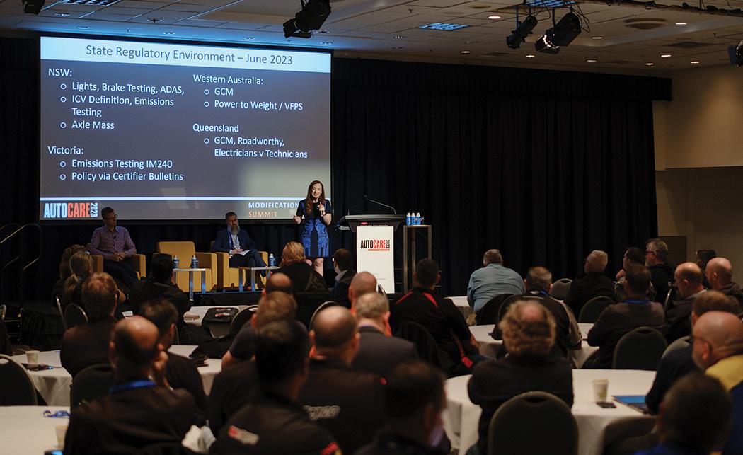
• Autocare 2025 is being held in Brisbane on the weekend of June 20 to 21. Hosted by the Australian Automotive Aftermarket Association (AAAA), Autocare is Australia’s largest automotive convention, offering an unprecedented training and networking opportunity to take your automotive career development, skills and business growth to the next level. Go to autocare.org.au
Add the Repco Authorised Service groups convention in early August and the Century Batteries Auto Electrical convention in late August to these events and you can see why 2025 is going to be busy.
I’m sure there are many other worthy events being held this year, so make time for you and your staff to network, do some quality training and share a beer or two with fellow technicians from all over Australia.
Everyone in the TaT team hopes to catch up with as many of you at one or more of these events during the year.


I’m sure I’ve previously said the first step in any diagnostic challenge is to have a clear route plan.
Like any intended route, you must also be prepared for the unexpected. Unlike a trip in your car – where the intended destination is known and so is the most logical route – a diagnostic task should begin blind, deaf and dumb.
Dare I say, we must carefully feel our way forward, guided only by symptoms and available test evidence.
One of our biggest challenges – which is only getting worse – is accessibility. This applies not only in the physical sense but also to live data, hot functions and adaptation routines.
My chosen topic for this issue is turbo testing, likely the most highly stressed component in the powertrain.
A turbo relies on a range of peripheral systems to function correctly, making it highly susceptible to cascading failures.
I intend to focus mainly on the variable-vane turbos (VVTs) used predominantly with diesel engines. Most of what I will cover also applies to fixed-geometry turbos.
The turbocharger is responsible for increasing the mass of air entering the cylinder during the intake stroke. It achieves this by increasing intake pressure, thereby overcoming the pumping losses (i.e. work done within the four-stroke cycle).
A turbo comprises two main sections: the exhaust turbine (hot side) and the compressor (cold side). Each turbo is unique to a specific engine, with the compression or force ratios determined by the relative vane sizes.
To prevent catastrophic failure or turbo stall, there must be a mechanism to manage boost pressure. This is achieved by a wastegate, which vents excess compressed air from the chargepressure system into the atmosphere or recirculates it back into the low-pressure side of the air-intake system.
The VVT is praised for its smooth response at low engine speeds, aided by the unthrottled diesel intake. At low engine speeds, the relatively low energy from exhaust gases is directed towards the outer edges of the exhaust turbine. This is achieved by variable vanes controlled by a pneumatic or electronic actuator. As boost pressure builds, the vanes redirect exhaust gases towards the turbine centre, thereby reducing boost.
Diesel engines often feature limited overboost at the lower RPM range and fuel-map reductions at the top end to further manage boost. VVTs incorporate a fail-closed control solenoid or similar mechanism which ensures virtually no boost in fail-safe or fault conditions.
The two most common turbo faults are underboost and overboost.
Underboost
Start the engine and observe the vane-actuation control rod articulating throughout its full movement range, reaching the maximum boost position. Keeping accessibility challenges in mind, conduct a pressurised smoke test to identify leaks.
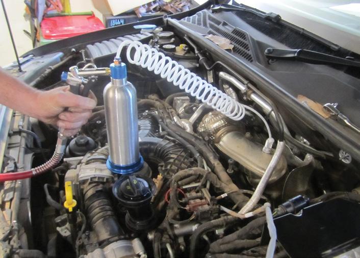
I was the original UK importer of the Redline Smoke Pro (pic 1) and modified it to produce two bar absolute pressure, which simulates the charge-pressure system’s expansion during turbo boost. Don’t stop at the first leak you find; after fixing the primary leak, smaller, more subtle leaks often emerge. Don’t overlook the possibility of internal leaks, such as through a faulty exhaust-gas recirculation (EGR) system.

To assess for a potential EGR leak, carefully monitor the air mass meter (AMM) values. An open EGR valve reduces the clean air-intake mass, which can be detected through serial actuation test plans. Although EGR valves provide feedback data, physical failures (e.g. a stuck valve door) can lead to misleadingly normal feedback values. Important: An AMM that undervalues air-intake mass will reduce boost. Conversely, an AMM that overvalues air-intake mass will increase boost.
I once encountered a case where – after installing a genuine new turbo and replacing the feed and drain hoses, oil and filter – the bearings failed within one mile of driving. The cause? A false increase in load tables due to incorrect AMM readings. Detailed serial data analysis revealed this after oil pressure at the turbo-feed gallery was verified.
Next, check the control vacuum at the pump and at the vane actuator. Divide the pressure at the actuator by the control-duty cycle to determine if a faulty control solenoid is responsible. For instance, if vacuum at the pump is 25 inch of mercury (inHg) with a 75 per cent duty cycle, the pressure at the actuator should measure 18.75 inHg.
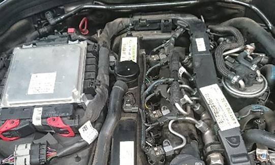
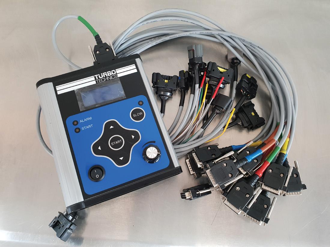
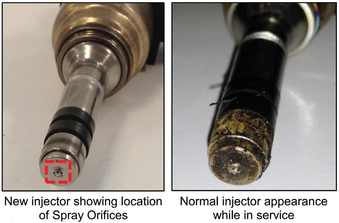
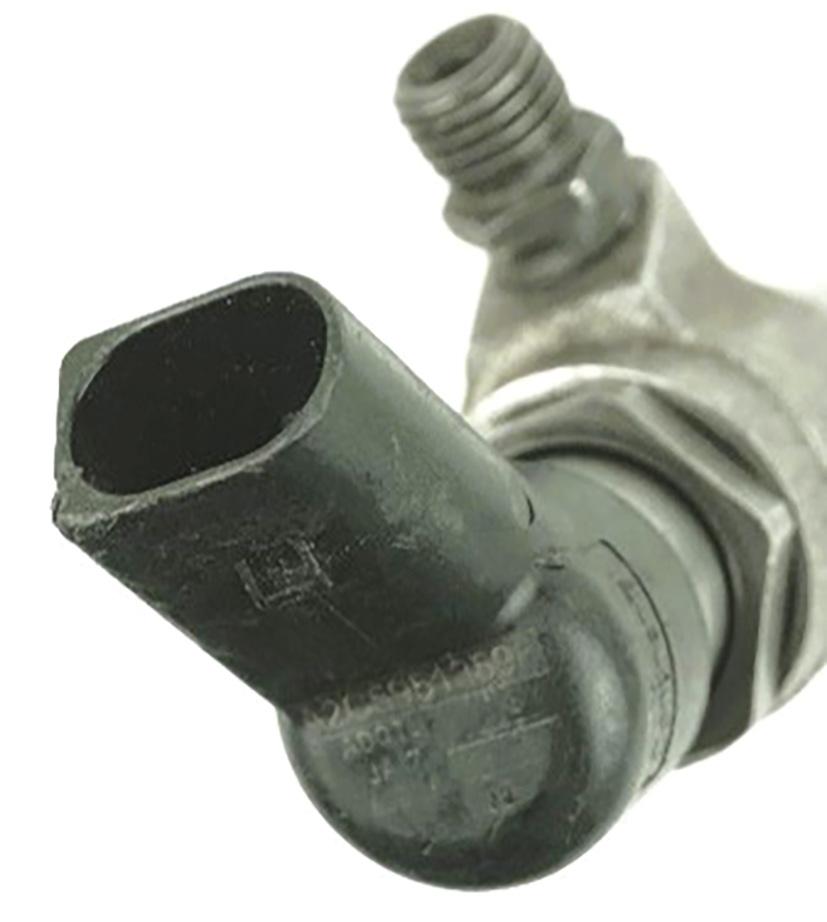
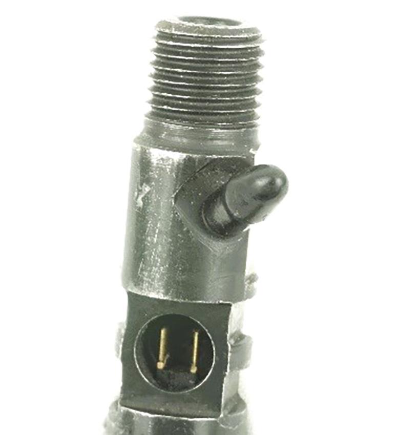
For electronically controlled actuators, use a test tool capable of inputting actuation percentage values while monitoring current flow and feedback data independently from the powertrain control module (PCM, pic 2). Maximum current typically ranges between 2.5 to 3A.
On a simpler note, remove the circlip from the vane-actuation rod and manually move the vane slip ring, checking for free movement.
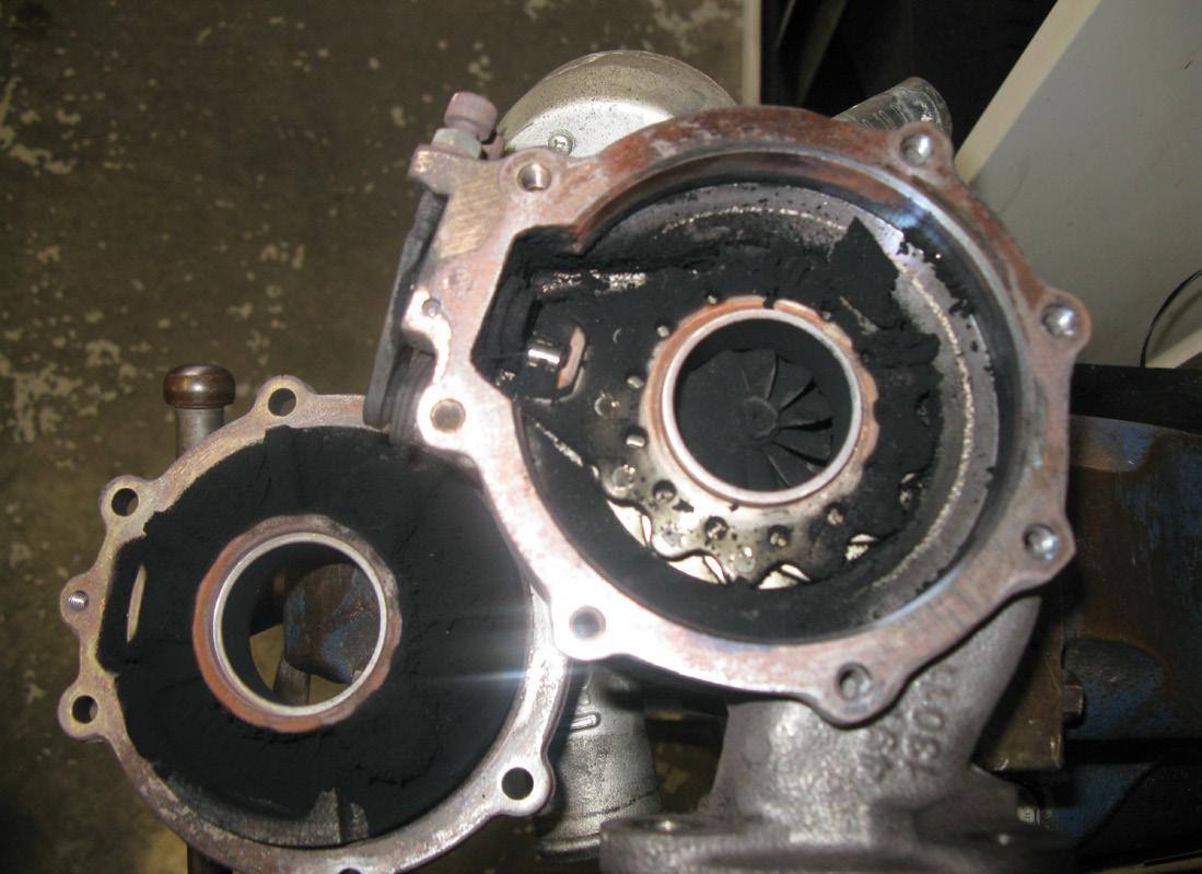
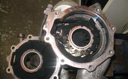
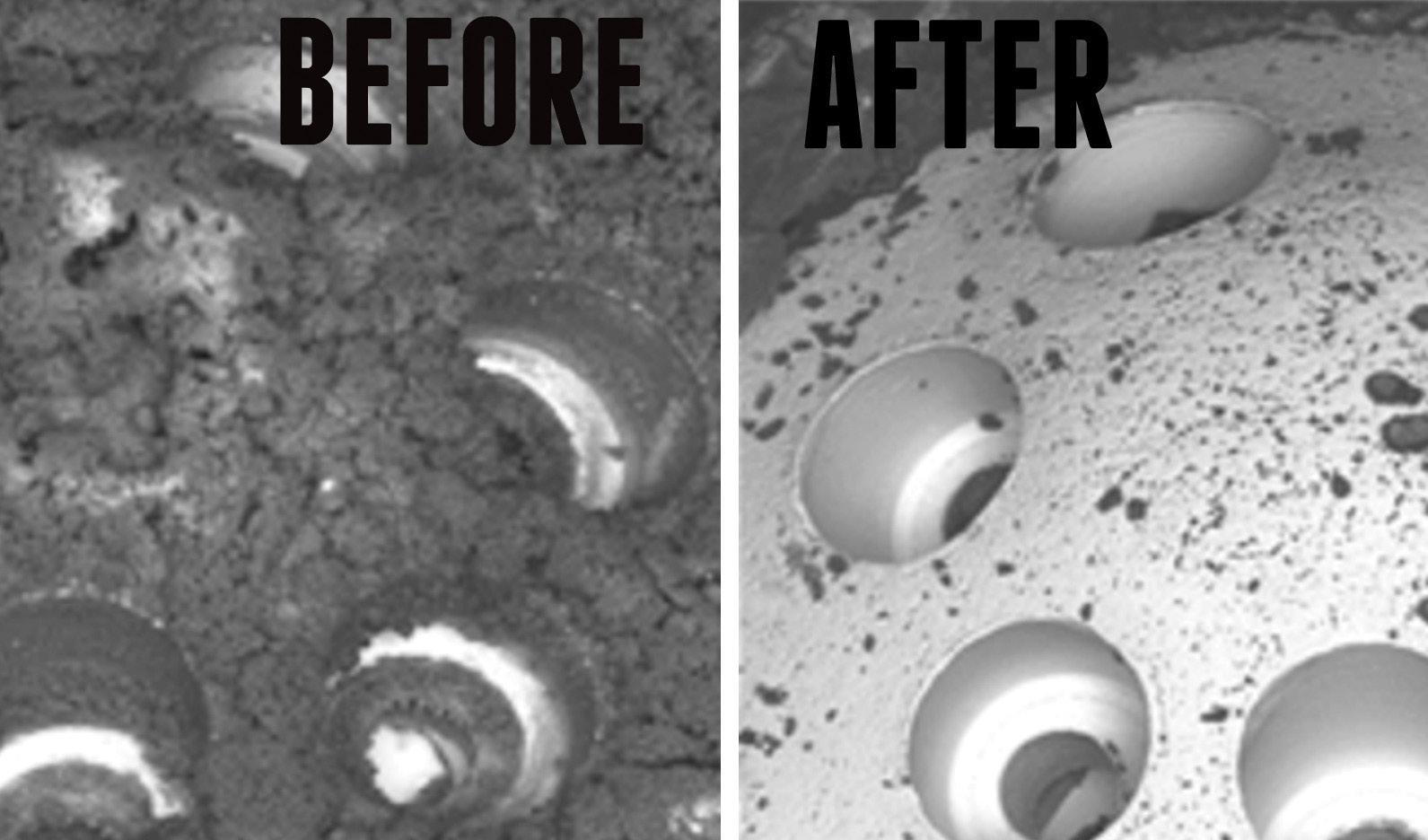
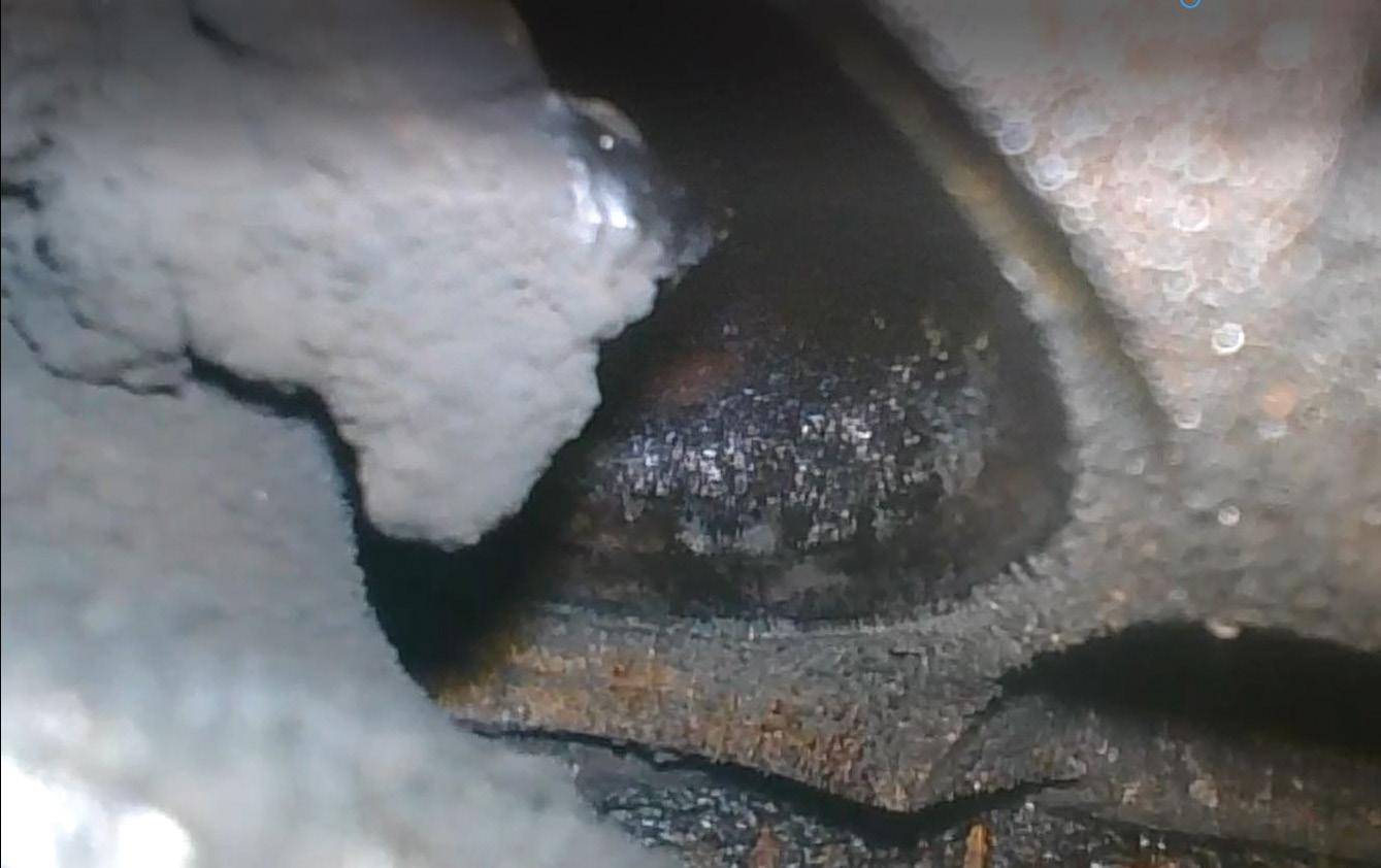
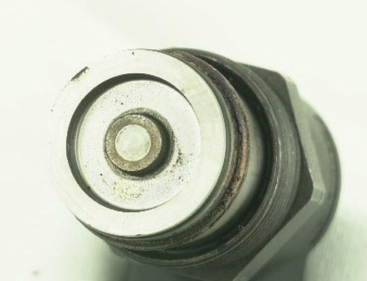
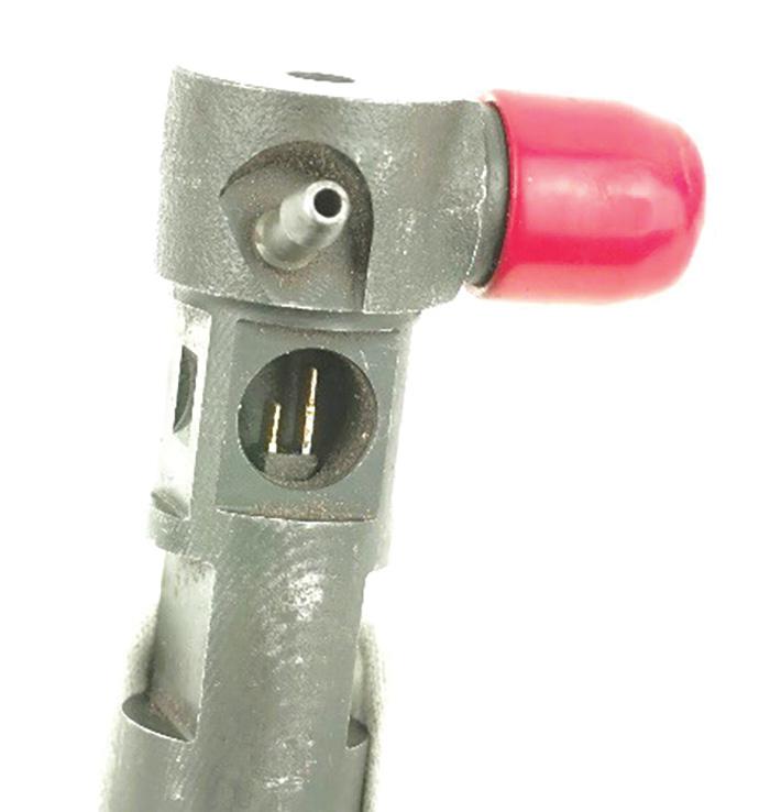
Overboost is most often caused by soot or carbon deposits on the vane-control mechanism (pic 3). Reflecting the prevalence of diesel performance upgrades, improper modifications by unqualified tuners also frequently lead to premature turbo failure. Compression ratios must be respected, which is why we rely on a skilled company to build our hybrid turbos using Inconel vanes and ceramic bearings. Emissions regulations have also introduced a raft of turbo-related problems. High and low-pressure EGR systems often recirculate excess soot from failed diesel particulate filter (DPF) treatment, resulting in high exhaust-system pressure that reduces air mass and turbo boost. Repeated active regeneration cycles dilute oil, causing unavoidable bearing failure.
Symptoms mimicking a restricted DPF may also indicate EGR cooler blockages or a partially seized selective catalytic reduction (SCR) exhaust-brake flap motor.
Long service intervals, incorrect oil specification and substandard filtration are among the most frequent problems.
The oil-feed pipe or banjo union often contains a gauze filter. I prefer to remove it and widen the banjo hole to improve oil-flow capacity.
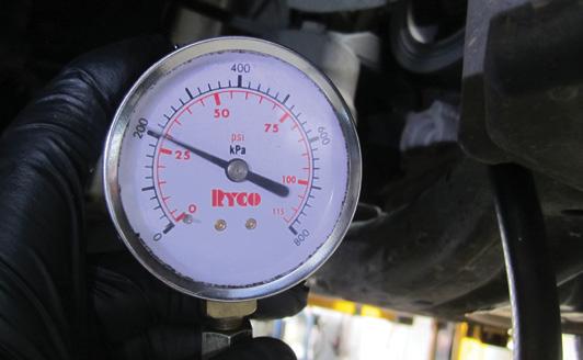
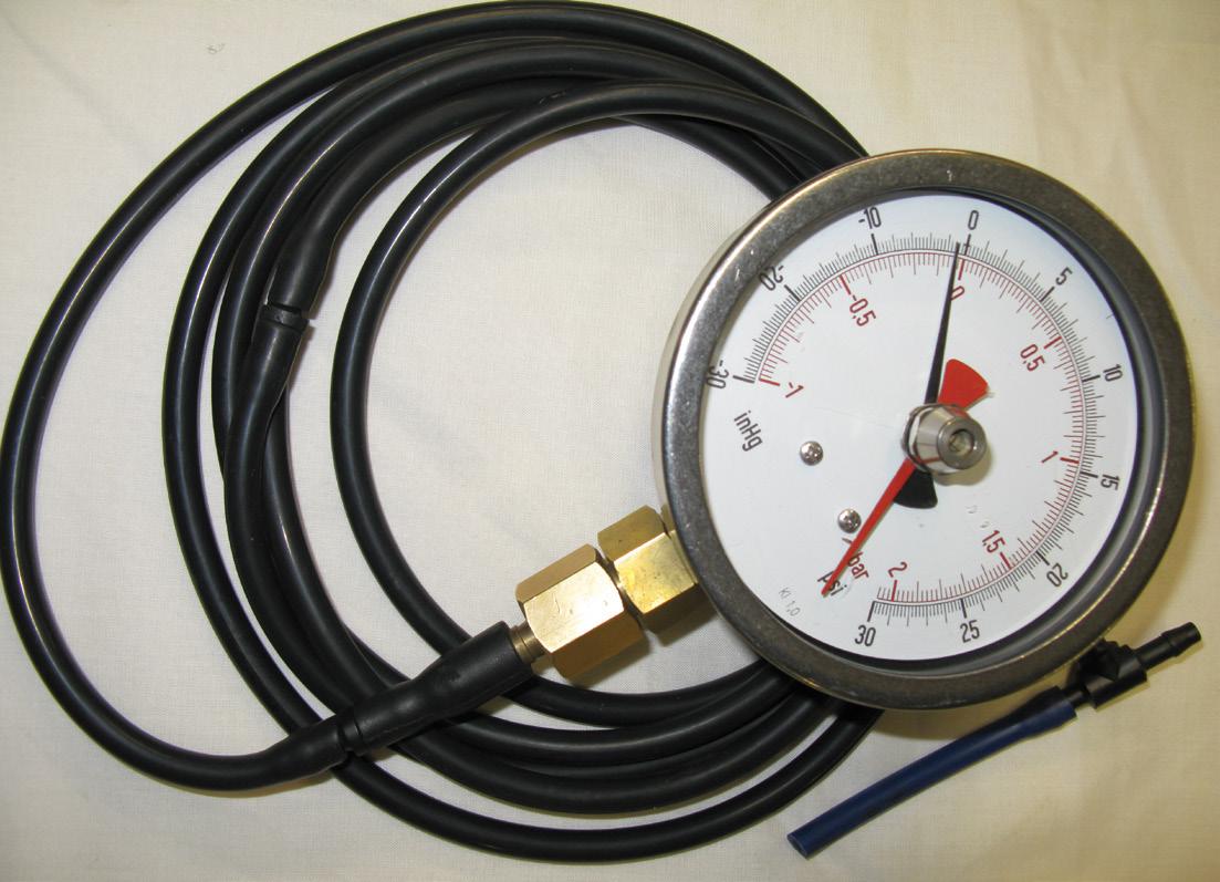
Finally, I feel a little guilty in not mentioning my favourite and most trusted tool, a four-inch undamped pressure gauge with a three-bar absolute range, which I had specially built (pic 4).
I guess all this comes down to customer education and ownership advice regarding the advanced powertrains that all cars now have. And that, my friends, is a responsibility we all share.
Electrically assisted forced-induction technology has redefined the capabilities of internal combustion engines (ICEs), addressing one of the key limitations of traditional turbochargers – turbo lag.
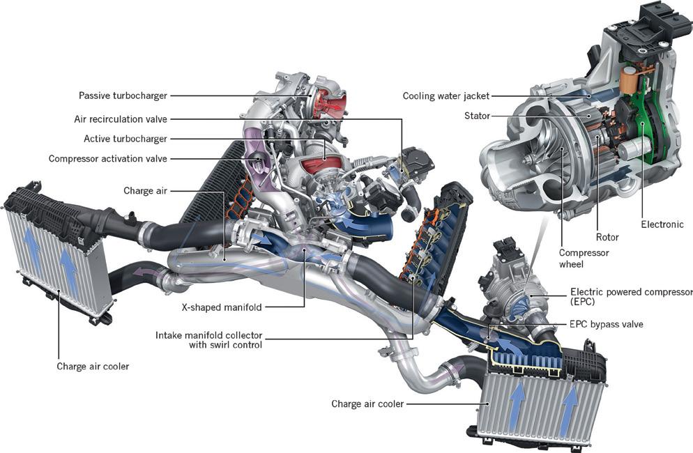
In this article, we examine the specifics of Audi’s Electric Powered Compressor (EPC) first seen in the 2016 SQ7 and Mercedes-AMG’s (in conjunction with Garrett) integrated electric turbocharger released in 2022, focusing on their functionality and distinct characteristics.
Audi’s EPC system operates as a 48V electric supercharger designed to supplement its twin turbochargers.
Air entering the system flows through the air filter and then to turbo one, which handles air flow at low engine loads. A bypass valve directs air around the EPC and turbo two when they are not in use, allowing turbo one to operate efficiently at these low-speed, partthrottle loads.
When the driver demands quick acceleration, the EPC bypass valve closes and the 48V EPC compressor is activated. This rapidly spools up to 70,000RPM in less than 250 milliseconds.
This immediate boost eliminates turbo lag for turbo one, delivering near-instantaneous throttle response.
As the engine reaches higher RPMs and turbo one achieves full spool, the EPC is deactivated and bypassed. At this point, the bypass valve for turbo two closes, allowing air flow to pass through both turbochargers during high engine output.
This sophisticated system is designed to ensure a smooth transition from electric to exhaust-driven forced induction, delivering seamless performance across all engine speeds.
A critical factor in the effectiveness of Audi’s EPC system is its reliance on a 48V system which operates parallel to the vehicle’s traditional 12V system. The high voltage is essential for managing the significant power demands of the EPC, which is driven by a 7 kilowatt (kW) motor. To understand the importance of this, consider the relationship between power, current and voltage (i.e. power = current x voltage). At 48V, the EPC draws 145A to produce 7kW of power. If the system operated on a conventional 12V setup, it would require a continuous current of 583A.
The 48V system not only supports the EPC but enables other advanced vehicle systems including advanced suspension actuators and mild-hybrid functionalities such as regenerative braking. This added complexity does have its drawbacks though, with the expensive 48V belt-driven starter/generator proving to be a common failure item, often accompanied by fault codes such as:


• P065C00 – Alternator mechanical characteristics – intermittent operation.
• P0CA700 – Hybrid battery discharge current too high.
• P0A7D00 – State of charge in hybrid battery low.
• P0B2900 – Hybrid battery ‘B’ low voltage.
The battery-discharge current and low-voltage codes are simply because the faulty starter generator is not charging it correctly.
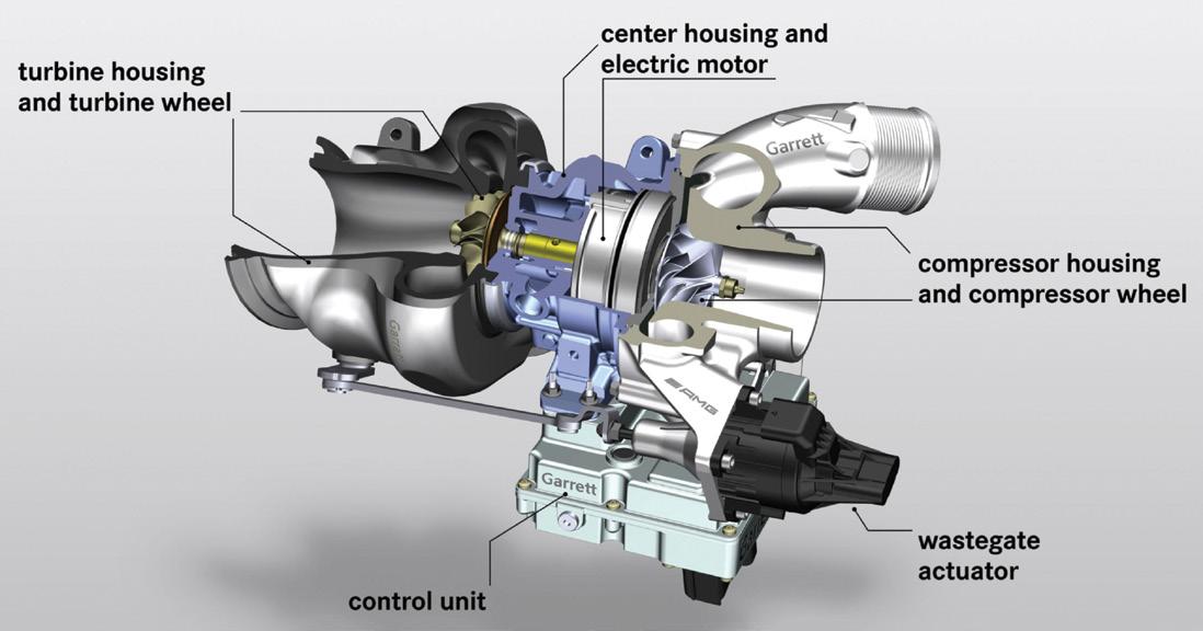
Mercedes-AMG takes a different approach with its integrated electric turbocharger, which combines electric assistance directly into the turbocharger itself.
In this system, a compact electric motor (rated around 2.2kW) is mounted directly on the turbocharger shaft between the compressor and turbine wheels. This motor accelerates the compressor wheel to an impressive 170,000RPM, providing immediate boost pressure and effectively eliminating lag.
As is common on modern turbos, an electric wastegate actuator is used to precisely control exhaust-gas flow through the turbine, optimising boost pressure, but in this case also ensuring smooth transitions between electric assistance and traditional exhaust-driven turbo operation.
Unlike Audi’s EPC, which functions as a separate supercharger unit, Mercedes-AMG’s system creates a more unified and compact design. The electric turbocharger in Mercedes-AMG’s system is also powered by a 48V electrical setup but is paired with a larger 0.9 kilowatt-hour (kWh) lithium-ion battery. This battery is charged via an integrated starter generator (a mild-hybrid motor mounted to the rear of the crankshaft), which recovers energy during deceleration and braking. Both systems leverage the growing trend of 48V electrical architectures, which are becoming increasingly popular in ICE vehicles that are not full hybrids or electric vehicles (EVs).
The use of 48V technology addresses the power demands of modern electric components, allowing automakers to achieve greater efficiency and performance without the need for high-current 12V systems. These 48V mild-hybrid systems are below the considered high-voltage limit of 60V DC, however as with any electric circuit it is still important to handle with care, particularly to avoid accidental short circuits during nearby work or repairs on the 48V system.
Audi’s and Mercedes-AMG’s innovations demonstrate the transformative potential of electrically assisted turbocharging. By bridging the gap between traditional forced induction and electrification, these technologies represent a significant step forward in the evolution of ICEs.
As automakers continue to refine and expand the use of 48V systems, the future of turbocharging is set to become even more efficient, responsive and versatile.

Jeff Smit
We have unique driving conditions in Australia
– ranging from congested capital city streets to vast outback highways. Both of these extremes present distinct challenges in ensuring good vehicle maintenance for our customers’ vehicles.
Whether it’s addressing our inconsistent fuel quality, tackling engine carbon build-up or maintaining modern diesel systems, treatments, chemicals and additives are proven and indispensable tools in the aftermarket automotive industry.
In this article we’re exploring the vital role these products play, particularly in optimising fuel systems, enhancing combustion and supporting critical components such as diesel particulate filters (DPFs), ensuring our customers’ vehicles deliver reliable performance and longevity.
The challenge of variable fuel quality
Fuel quality in Australia can vary significantly, especially between metropolitan and country areas. Factors such as prolonged storage, long distribution distances and fuel contamination can impact performance and lead to issues such as clogged injectors, reduced fuel efficiency and engine wear.
Additives designed to clean and protect the fuel system address these challenges by:
• Removing deposits that accumulate on injectors and combustion chambers.
• Stabilising fuel to prevent degradation during storage.
• Improving combustion efficiency, reducing emissions and enhancing performance.
For diesel engines, anti-gel additives prevent fuel from thickening in cold climates, while biocide treatments eliminate microbial growth in fuel tanks, a common issue in humid or remote areas.
Modern engines, particularly direct-injection petrol (GDI) and diesel models including common-rail diesels (CRDs), offer greater efficiency and performance but are more susceptible to carbon build-up.
Direct-injection engines
In a GDI system, fuel is sprayed directly into the combustion chamber, bypassing the intake valves. This lack of cleaning action allows carbon deposits to form on the valves, leading to:
• Rough idling and misfires.
• Decreased performance and fuel economy.
Diesel engines
Diesel engines with exhaust-gas recirculation (EGR) systems and highpressure fuel injection are prone to soot and carbon deposits, causing:
• Clogged injectors and intake manifolds.
• Reduced engine efficiency and DPF blockages.
Specialised fuel additives and intake cleaners address these issues by:
• Dissolving carbon deposits in combustion chambers, intake valves and exhaust systems.
• Enhancing fuel atomisation for cleaner combustion and reduced soot production.
DPFs are essential for reducing harmful emissions in modern diesel vehicles. DPFs trap soot and particulate matter but require regular regeneration to burn off accumulated soot. Challenges arise when:
• Vehicles are frequently driven at low speeds or on short trips such as city driving, preventing the exhaust from reaching the high temperatures required for regeneration.
• Low-quality fuel or poor combustion increases soot production, accelerating DPF clogging.
1. Fuel-borne DPF cleaners: These additives lower the ignition temperature of soot, aiding regeneration cycles even under lessthan-ideal driving conditions.
2. Cleaner combustion: Additives that optimise combustion reduce the production of soot, lightening the load on the DPF.
3. Manual DPF-cleaning solutions: When a DPF becomes clogged, chemical cleaners can restore functionality without the need for costly replacements.
Australia’s diverse driving conditions significantly impact vehicle maintenance needs.
Urban driving and short trips
City driving often involves short trips that prevent engines from reaching optimal temperatures, leading to:
• Condensation and sludge formation in the engine oil.
• Soot accumulation in the DPF.
Oil additives and fuel-system cleaners can mitigate these issues by maintaining lubrication properties and assisting with DPF regeneration.
Towing and long-distance driving
In regional areas, diesel vehicles are often used to tow caravans or heavy loads. These conditions increase engine stress and soot production.
• High-performance fuel and oil additives enhance combustion efficiency and reduce wear on engine components.
• Anti-corrosion and anti-water treatments prevent fuel-system damage from contaminated diesel.
The use of treatments, chemicals and additives delivers significant environmental and cost-saving benefits:
• Reduced emissions: Cleaner combustion and well-maintained DPFs contribute to fewer pollutants, aligning with Australia’s strict emissions standards.
• Lower maintenance costs: Preventative use of additives reduces the risk of expensive repairs or part replacements.
• Improved fuel economy: Enhanced fuel-system efficiency translates to savings at the pump.
Australian motorists, our customers, are increasingly recognising the value of proactive maintenance. By incorporating treatments, chemicals and additives into their vehicle-care routines, drivers can address challenges such as carbon build-up, fuel-system inefficiencies and DPF blockages before they become costly problems.
Pic 3: Intake-valve deposits, particularly on the stem, affect air swirl and lead to combustion abnormalities. Intake-manifold access can be difficult but a 90-degree camera through a spark-plug hole can give a great view.
The aftermarket-automotive industry in Australia is embracing the use of treatments, chemicals and additives to meet the unique demands of the nation’s motorists. Whether combating variable fuel quality, addressing carbon build-up in modern engines or adapting to diverse driving habits, these products play a pivotal role in maintaining vehicle reliability, efficiency and environmental compliance. As Australian drivers continue to seek solutions for keeping their vehicles in top condition, the importance of these treatments is only set to grow.
For Australian motorists, investing in high-quality aftermarket treatments is a cost-effective strategy to keep their vehicles running smoothly, no matter the journey.
This car presented at a TaT workshop with the diesel particulate filter (DPF) light on and a fault code registered in the engine computer. The vehicle was also frequently going into limp-home mode.
I performed all the normal pre-inspection and inspection checks – there were no mechanical issues to be found with this vehicle.
This isn’t always the case with DPF faults. Most of the time the underlying cause for a DPF light is a mechanical fault, including burst hoses or intercoolers, failed components or sensor faults.
On further discussion with the owner, I discovered the vehicle was being used for a lot of short journeys and no long or hardworking trips. This is a real problem for a vehicle fitted with a DPF because the exhaust temperatures need to reach specified levels or thresholds – if they don’t, the systems that allow for a passive regeneration of the DPF will not enable it to happen.
The end result is excessive soot load in the DPF, which leads to restricted flow, possible blockages and, at a bare minimum, performance issues, the check-engine light (CEL) or other warning lights coming on and ultimately limp mode.

There are many products on the market today that claim to be able to clean a DPF, but what really works?
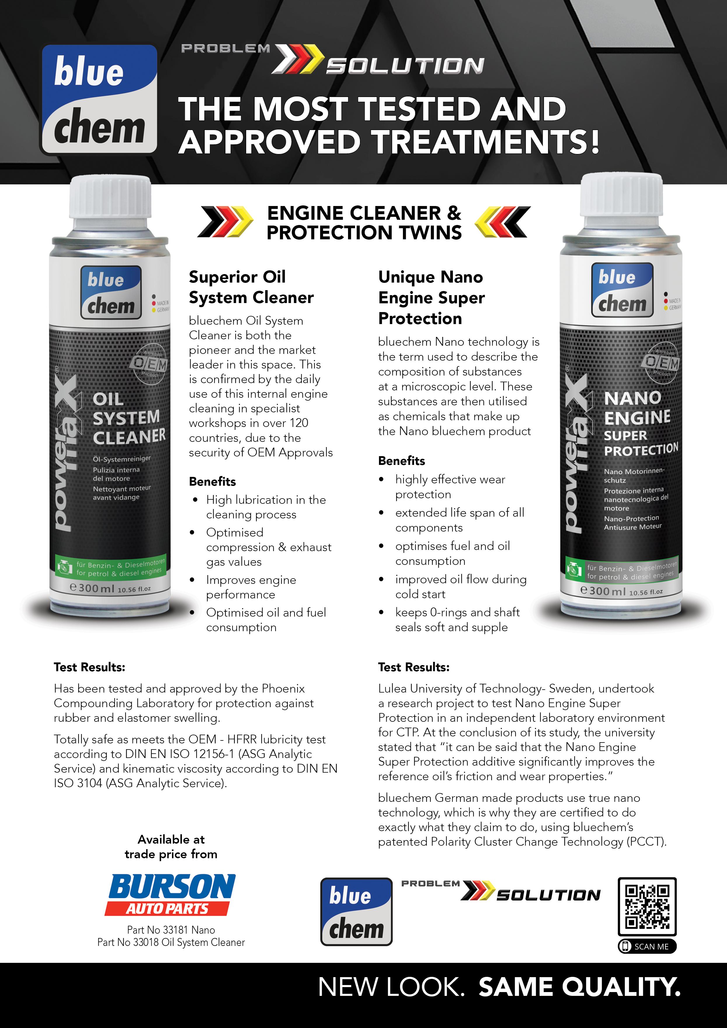
With this vehicle I decided to road-test bluechem Top Gun Cleaner (pic 1), then test the results. At the start of the cleaning process the pre-inspection had already been completed, so I checked the scan-tool data, pressures and temperatures, noting a calculated soot mass of 39.56g (pic 2).
With the DPF warm (i.e. not hot), I used the DPF Top Gun Applicator (p/n 33480) to add the bluechem Top Gun Cleaner 1 Litre (p/n 33481) to the DPF system via the removed rear oxygen (O2) sensor (pic 3) – you can also use the rear hose from the pressuredifferential sensor. I then allowed the Top Gun Cleaner to penetrate for five minutes. Note: If the DPF is quite blocked and won’t allow the entire one litre of product to be added, you can start the engine to help push the product through the DPF. After allowing the five-minute penetrating time, I reinstalled the O2 sensor before adding three products to the fuel tank; DPF Power Clean 375mL (p/n 33450), Oxicat 300mL (p/n 33230) and Common Rail System Clean and Protect 375mL (p/n 33098).
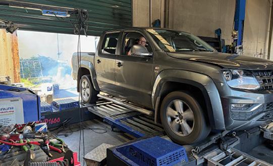
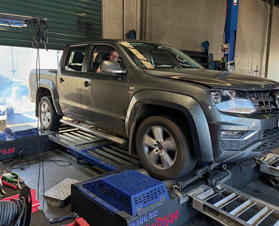
Next, I started the engine and allowed it to idle for 15 minutes to increase the temperature in the DPF. I then ran the vehicle on the dynamometer under loaded conditions for approximately 25 minutes (pic 4). If a dyno isn’t available, a road test is fine but the vehicle must be driven under some loaded conditions.
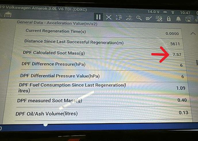
After this, I rechecked the live-data readings, revealing a significant drop in DPF calculated soot reading – it was now 7.57g (pic 5).
Next, I road-tested the vehicle. Engine power was restored and there was no CEL or limp mode anymore. The outcome was a great result for a product that is easy to use and apply to the DPF system.

The vehicle was returned to the owner with a firm recommendation they drive it in a more spirited manner to ensure the engine and exhaust temperatures were able to reach the required levels so this problem wouldn’t occur again in the future.
If you are faced with a situation where a vehicle is continually driven on short trips, DPF Power Clean (p/n 33450) and Oxicat (p/n 33230) can be added to the fuel tank in between services to help keep the DPF system working better.
It’s worth noting the solution should not be added to a hot DPF at the start of the procedure as the rapid change of temperature can damage the DPF.
All up, a good experience from a product that really works.

bluechem DPF Gun with the combined treatments provides a comprehensive solution for both the workshop and the customer. Made in Germany for over 30 years and sold in over 110 countries with various OEM Approvals. bluechem is a safe total solution package!
Available at trade price from


With so many varieties of injectors on offer, it’s certainly mind-boggling to wonder: how do you get to know each injector, its operation and, most importantly, how to diagnose each type?
While writing my final articles for 2024, I’ve been reflecting on the year. The diagnostics that stood out often involved injector replacements, which were frequently not the source of the failure.
The most important parts of injector replacement involve understanding the cause of the initial failure and proper preparation.
Just as significantly, technicians must understand the precautions required to avoid many of the underlying risks observed when replacing them.
1. Replacing injectors without finding the cause of failure can damage a new set of injectors. Diesel fuel systems require 100 per cent diesel fuel for lubrication and hydraulic operation.
2. Not performing a compression test before replacing injectors. An ECU constantly adjusts injectors for smoother running and a compromised injector spray pattern can wear the bores excessively, leading to low compression. Installing new injectors under such conditions can worsen engine misfires.
3. Failing to inspect for bent rods before quoting injector replacements. Bent rods were a frequent discovery this year, often caused by excessive cleaners down intakes or failed injectors.
4. Repairing a valve-cover leak without prepping for injector replacement. Once an injector has been forcibly removed, it’s likely damaged and may not function properly afterwards.
Contaminated diesel passes through the fuel filter, lines, pump, rails and pipes, ending up in the injector and engine. It is impossible to successfully flush a pump, rail and injectors. What causes an injector to fail will often lead to another fuel-system component failing soon after. Hydraulics do not operate correctly with water, petrol or air contamination.
Now let’s dive into part three of this series on fuel-system control valves, ID and diagnostics by exploring a few more injector manufacturers, their unique designs and common faults.
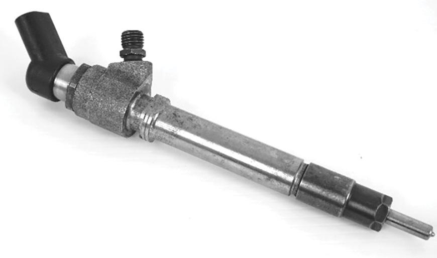
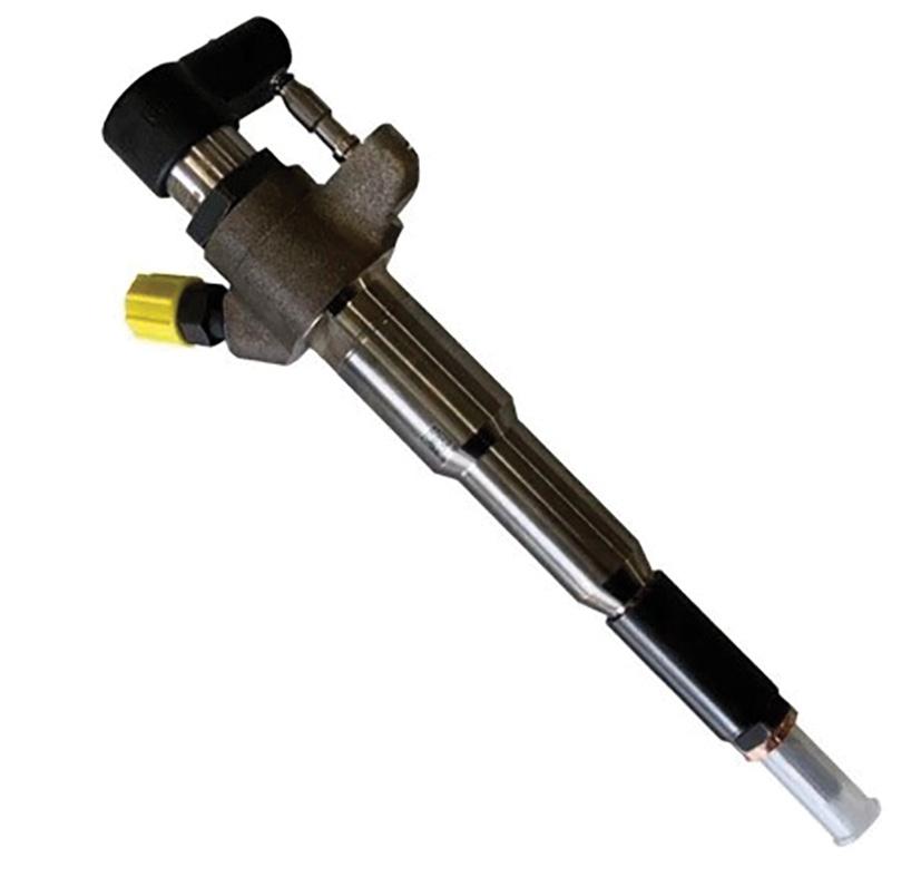
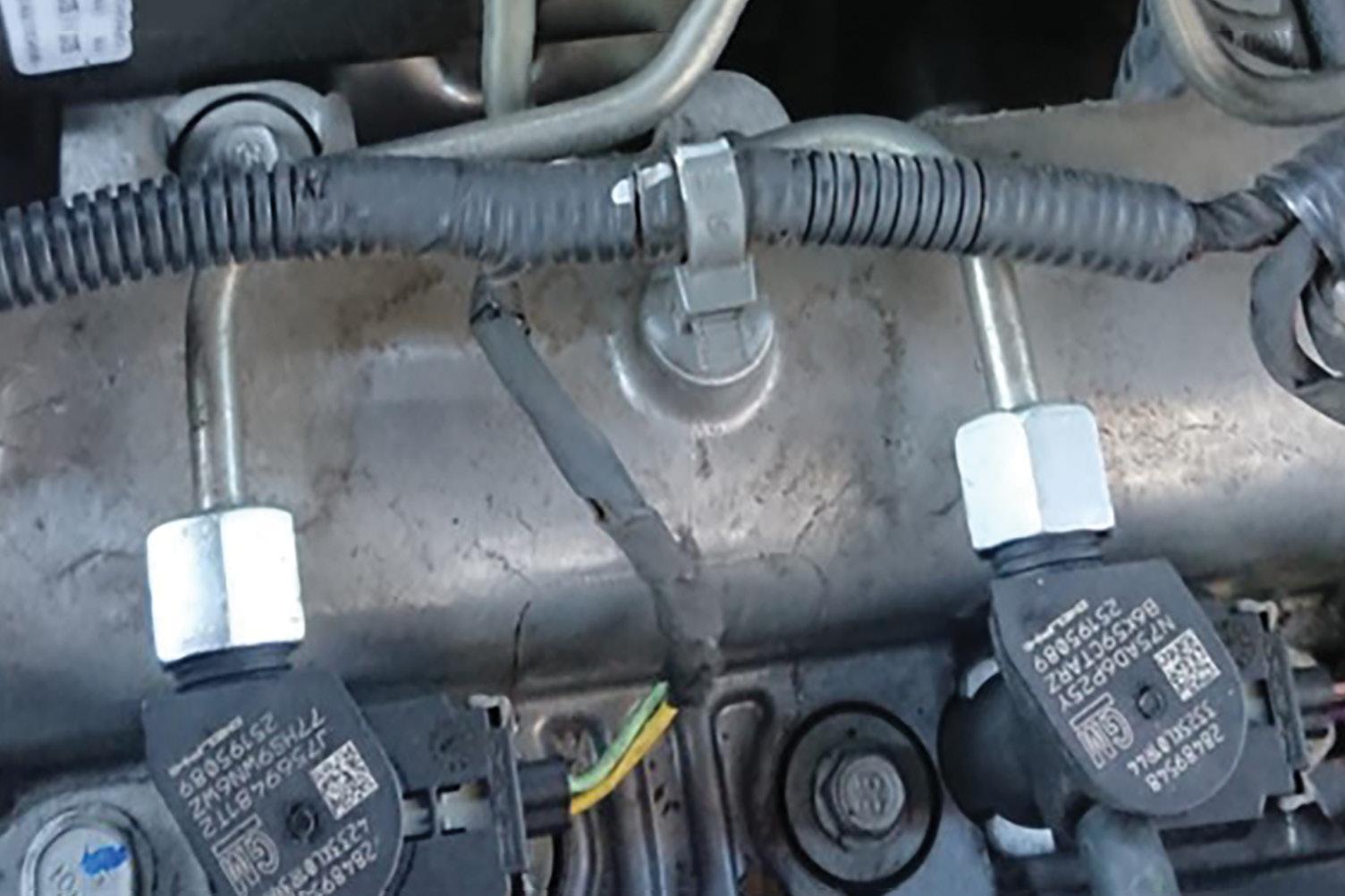
Originally developed by Siemens, the Continental injector is exclusively a piezo design. It is primarily fitted to passenger vehicles and only a small number are found in commercial vehicles.
Popular applications include Citroën, Ford (Ranger), Mazda (BT-50), Land Rover, Peugeot and later model Volvo vehicles, most of which come from the Ford/Peugeot joint venture PSA.
The Continental injection system is also used in Renault engines, which form the basis for the Nissan NP300 Navara, Renault and Mitsubishi commercial vans, as well as some VAG group engines with a limited range of Continental injectors.
• Identifying features
The Continental piezo injector has changed little since its first release in the late 1990s. In pic 2 and 4, you can see a slight change in the shape of the actuator. The return remains outside the cast body but the outlet has been redesigned from a female to a male fitting. This change likely addressed leakage issues in the earlier design while standardising OEM plastic return fittings to reduce costs.
The solenoid features an air-gap design, showcasing the ultra-fine tolerances in this unique injector. Such tight tolerances
allow very little margin for error. If the solenoid top is loosened, the only safe solution is to replace the entire injector. Without proper repair tools and testing equipment, resetting the air gap is impossible. Even if the engine starts, improper repair can lead to catastrophic engine failure.
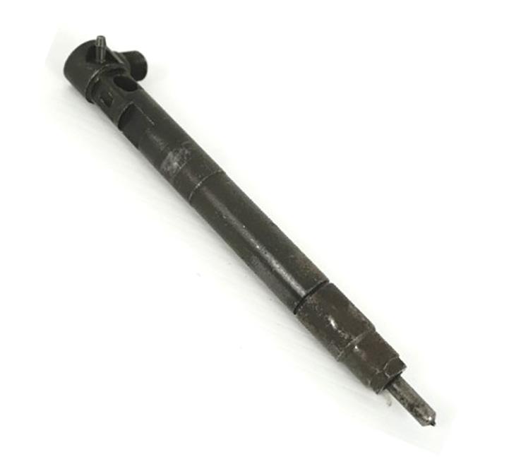
Delphi has been manufacturing electromagnetic solenoid injectors since the late 1990s. While piezo injectors are rare from Delphi, one notable case occurred in 2008 with the Mercedes-Benz OM651 engine, which had major injector recalls for OM651-powered models such as the C220, C250, E220 and E250.
These Delphi piezo injectors experienced high failure rates, causing limp mode or complete engine failure. In some cases, random over-revving led to engine damage. Mercedes eventually replaced the piezo injectors with electromagnetic solenoid designs, updating the ECU and other system components to match.
• Working with Delphi injectors
Delphi common-rail diesel (CRD) injectors often develop air locks soon after installation, preventing the engine from
starting. Sometimes, the engine will start but hunt, stall or log cylinder-specific fault codes. This issue is particularly common with brand-new Delphi injectors.
To address these bleeding difficulties, Diesel Help Australia created technical bulletins specific to each OEM. Examples include Hyundai iLoad, Great Wall, Mercedes-Benz Vito/Sprinter, Tata, Mahindra, SsangYong and Holden Captiva.
One of the most popular bulletins has been TB1163, covering the 2013 Holden Captiva 2.2-litre engine, which often fails to start after injector removal. Unlike most Delphi systems, which recommend unplugging the suction-control valve, Captiva instructions advise unplugging the rail sensor instead. This ensures maximum rail pressure, assisting with air purging. The injectors should remain electrically connected but the fuel return should be isolated to prevent air re-entering the system.
• Identifying features
The early Delphi injector uses a wire clip to secure it to the body. The harness connector has a dust seal, which also ensures a rigid connection. If this seal is damaged or missing, shorts may occur, leaving carbon deposits on the connector and injector. Avoid using water or chemical cleaners; use an evaporative, non-corrosive cleaner instead. When in doubt, replace the connector as seals are not sold separately. The later design Delphi has a distinctive change in the terminals. One is longer and the harness uses a secure lock feature. This has reduced the movement but we have experienced issues after cleaning the engine with water and detergents.

In the next part of this series, we will continue with the explanation of Denso injectors.

Potential and limitations
AI is a fast-moving technology and many are enjoying and utilising the advancements being made. I’m sure some of our members are well and truly familiar with AI and probably have used it, and those with experience using this great tool will understand the tool’s limitations and strengths and the importance of being specific and giving it as much detail as possible.
Giving the details
To get the best results from Tech Tina, you should provide as much detail as possible. The more specifically you describe the issue, the better she can assist.
For example, when asking about a vehicle issue, include the make, model, year, engine and fuel type, along with any specific symptoms or diagnostic data and any parts you may have already repaired or replaced. This will considerably help Tina narrow down the possibilities and give you the most accurate guidance.
What can I ask?
Tina has a one-tracked mind; she loves talking about all things cars and not much about anything else. You can try to make small talk but you will find she is very focused and will promptly steer you back to your problematic vehicle.
While Tina enjoys assisting with your
Tech Tina is our artificial intelligence (AI) powered assistant. She is designed to help TaT members with vehicle information, diagnostic troubleshooting and repair guidance and the sister of Tech Tony, our technical-assistance AI.
Tech Tina focuses on providing fast and accurate answers to a technician’s vehicle-related questions, saving time and streamlining their work, making this tool essential when used correctly.
diagnostic/testing steps and specifications, keep in mind she is still a young, learning AI and can make mistakes. If in doubt, it’s always best to compare the results to factory data.
If you require more in-depth technical assistance, I highly advise using the Technical Assistance page on the TaT website to get help from the TaT Tech Team and your peers.
A fun feature is Tina’s 10 personality settings, which allow you to choose the tone of her responses.
Setting one is formal and sticks strictly to the point, making it great when you need a professional, no-nonsense response. Setting ten, contrastingly, is more casual, giving Tina a more relaxed and conversational tone. In between, you will find a range of styles that offer different flavours of interaction, some of which are unique, but we won’t spoil the surprise for you. Playing around with these settings can make your interaction with Tina effective and enjoyable, so feel free to experiment.
To help get the most out of Tech Tina, a ‘Common Search Examples’ button has been included to list some of the more frequently asked questions, serving two purposes:

1. Save time: Questions such as, ’Explain the differences between a built-in regulator alternator and the ECUcontrolled smart-charge charging systems’ are already written out, so you will save time by not having to type the entire sentence out yourself.
2. Detail level: These common search examples also help to demonstrate how detailed your questions to Tina should be. The more information Tina is given, the better and more accurate her answers will be.
Tina will remember your previous questions within a session, which makes it easy to ask follow-up questions, removing the need to give the original details repeatedly. Another helpful tool is the ‘Clear Conversation’ button. If you are moving on to a different issue or vehicle, it’s a good idea to clear Tina’s memory by pressing this button. This will ensure she is not relying on any prior context when responding to your new line of questioning. A fresh start leads to clearer answers.
While the information provided by Tech Tina can be helpful, remember that she has limitations. She cannot provide wiring diagrams, pinouts, belt layouts, images or copyrighted material.
For those specific needs, you need to refer to other resources within the TaT platform such as the ‘OEM Info Resource’.
Tech Tina will be a valuable tool for many of our members, provided she is used correctly. We designed Tech Tina to help streamline the diagnostic process and with her 10 different personalities, she adds a touch of fun to the conversation while hopefully giving you the answers you need. Just remember to give her detailed questions for the best results and clear the conversation before switching topics. Tina is always here to lend a hand – just don’t expect her to pull up wiring diagrams!
Try out Tech Tina at tat.net.au/scandata/aiteam/techtina.php and discover how she can save you time in the workshop

Autocare 2025, Australia’s largest automotive training event for technicians and workshop owners, will showcase a trio of worldrenowned international automotive trainers.
Hosted by the Australian Automotive Aftermarket Association (AAAA) and proudly sponsored by mycar Tyre & Auto, this unmissable convention will take place on June 20-21, 2025 at the Brisbane Convention & Exhibition Centre (BCEC).
Autocare 2025 recently announced three industry-leading US-based trainers –Brandon Steckler, Keith Perkins and Tomi Oliva – who, alongside Australia’s top technical trainers, will deliver what is being pitched as the most comprehensive Technical Training Program ever seen in Australia. This program is designed for technicians seeking to stay at the forefront of automotive technology.
Steckler, a standout trainer at Autocare 2023 and the Technical Editor of Motor Age, returns due to popular demand to share his expertise. He will lead two in-depth sessions, A Logical Approach to GDI Driveability Concerns and Mastering Scan Tool Data Interpretation.
Perkins, a highly credentialed diagnostics expert and owner of L1 Auto Group in
Oklahoma, will host the sessions Diagnostics Beyond the Silver Bullet, J2534 Programming – European Vehicles and Network Failure & Diagnosis
Oliva, an esteemed diagnostics and module reprogramming specialist and owner of SJ Auto Solutions in Chicago, will lead the sessions J2534 Programming for Kia/Hyundai, Subaru & Toyota and J2534 Programming for Ford, Mazda & General Motors
Other valuable technical topics at Autocare 2025 include electric vehicle (EV) and hybrid developments, battery and charging systems, diesel and emissions-control diagnosis, Picoscope essentials and more. These sessions are designed to arm technicians with the tools and knowledge needed to address the industry’s most pressing challenges.
‘As Australia’s premier training event, we’ve curated the best international and Australian technical trainers to provide maximum value for technicians looking to excel in vehicle service and repair,’ said AAAA CEO Stuart Charity. ‘Autocare 2025 is the


only event where you can learn from three highly regarded US automotive trainers plus Australia’s best, all under one roof.
‘The strong focus on J2534 programming at this event comes at a pivotal time for the industry as technicians increasingly leverage full access to OEM information made possible by the mandatory data sharing law and the Australian Automotive Service and Repair Authority (AASRA) portal.’
In addition to the Technical Training Program, Autocare 2025 will feature a Workshop Management Program tailored for business owners and managers. This program will focus on improving profitability, streamlining operations and addressing key industry trends with practical strategies to futureproof a business.
Register now for Autocare 2025 and be part of Australia’s most transformative automotive training event. Early-bird tickets are available at autocare.org.au
This 2009 BMW 325i with 142,533km on the clock had a transmission issue: it wouldn’t engage sport mode (‘DS’ mode) and the ‘D’ indicator on the shifter wouldn’t light up.
Testing confirmed the issue. Checked for fault codes but none were logged. Live data from the shifter position showed incorrect readings when attempting to engage DS mode.
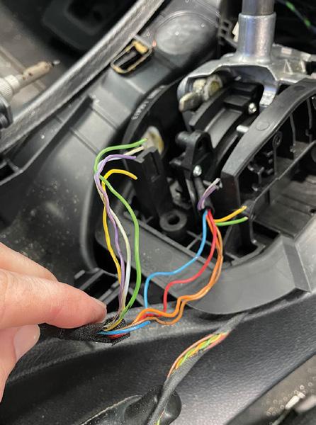
Removing the covers and shrouds around the gear shifter revealed broken wires in the loom. Tugging on the wiring confirmed the issue.
Accessing the broken wires required unbolting the shifter mechanism from the vehicle using three T30 Torx bolts. Wiggled the shifter assembly upward while leaving the shifter cable connected. Further disassembly involved removing the plastic cover from the side of the shifter, secured by three T9 Torx screws. This provided access to the damaged wires, which were repaired before reassembling the system.
The repair resolved the issues, restoring sport-mode functionality and the D indicator light.
Diagnostic time for this job was one hour and repair time 2.5 hours.
Winston Hannaway Winnie’s Auto Repair RONGOTAI, NEW ZEALAND

The car would crank but not start. The vehicle’s injectors, ignition coils, crank position sensor (CKP), camshaft position sensor (CMP), fuel pump, fuel filter and keys had all been replaced prior to me being called.
Problem summary
Confirmed the complaint. Found the engine would crank but not attempt to start. There was no engine light when the ignition was turned on or during cranking.
Diagnostic sequence
Checked for diagnostic trouble codes (DTCs) but there was no communication with the ECM. Checked all fuses – they were OK. Checked the operation of the ignition coils and injectors –neither were being driven by the ECM.
Checked the operation of the ignition keys and checked the coil-antenna operation – they were OK.
The keys were readable and when inserting the key/s into the ignition the security light stopped flashing – it was OK.

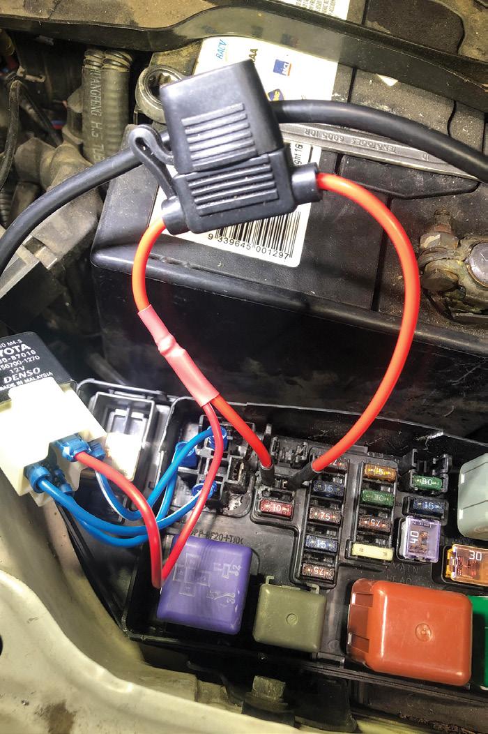
Checked the powers and grounds to the ECM and found the ignition power at connector D pin 23 was not present. This power comes from the electronic fuel-injection (EFI) relay through fuse 2 in the engine bay.
Checked the EFI relay. Found terminal 30 on the relay socket was melted/damaged and there was no power present.


Fuse 2 also provides power to connector D pin 14. Power was present at pin 14, so I suspected an internal fault in the engine-bay fuse box.
Fitted temporary jumper wires to power the EFI relay – power was now present at pin 23 (pic 1).
I could now communicate with the ECM, so checked for DTCs –none were present.
Checked LiveData and monitored parameter IDs (PIDs) – everything seemed to be normal via the data.
The car was now hard to start. It would intermittently start and run for a short time, running rough, then turn off.
Checked the operation of the ignition coils and injectors – they were both now being driven by the ECM. Found when the engine was running then stalling/shutting off, the ignition coil was still being driven but the injector drive would cut out suddenly.
I recommended the replacement of the reluctor/trigger. This issue can cause incorrect fuel-injection timing, hard starting and stalling. It can also cause the ECM to shut the injectors off as it is receiving too many triggers per revolution (compared to the CMP).
I informed the workshop this may not have been the issue causing the injectors to shut off, but it needed to be rectified first.
Recommended time
Diagnostic time was one and a half hours, taking into account preparation and research. The repair was performed by the workshop.

Checked operation of the CKP and CMP sensors (pic 2). Found both were giving readable signals but the CKP appeared to have two top dead centre (TDC) triggers (pic 3). Pic 4 shows a known good signal for comparison.
Fault description
Removed the CKP sensor, checked the reluctor wheel with a borescope and found the reluctor was missing a tooth (pic 5).
Thanks to Jack Mackay for redirecting me towards the CKP signal.
Repair Solution by TaT Tech Team member Gary O’Riain (GO Diagnostics)
Customer complaint
The vehicle had stopped as the customer was driving on the highway.
Problem summary
Confirmed there was no crank and no start. Researched Repair Solutions on the TaT website and noted a common instrumentcluster fault.
sequence
The vehicle was towed in from another workshop for diagnosis. Many tests had been carried out and a multitude of trims had been removed. An attempt had been made to solder the instrument cluster’s circuit-board connector pins as this is a common issue with the vehicle.
Only three systems were available for scanning. Retrieved the following codes:
• U1900-E0 – CAN communication bus fault ‘receive error’.
• U2202-E0 – Invalid configuration data received.
• B1204-60 – Fuel sender circuit short to ground.
• U2197-20 – Invalid vehicle speed data.
• U2200-20 – Invalid data for odometer.
• U2510-60 – Invalid data for vehicle security.
With the ignition off, the immobiliser would flash as expected. During a crank attempt, the dash display would disappear for a short time, then warnings such as ‘engine systems fault, fuel computer data error’ would appear on the cluster display (pic 1).
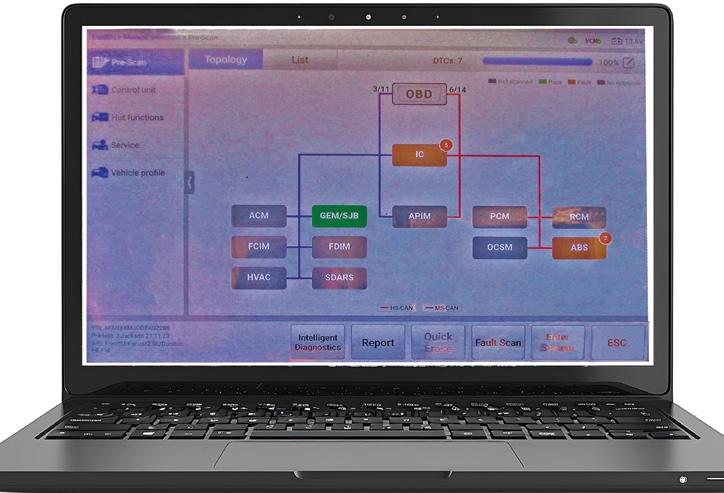
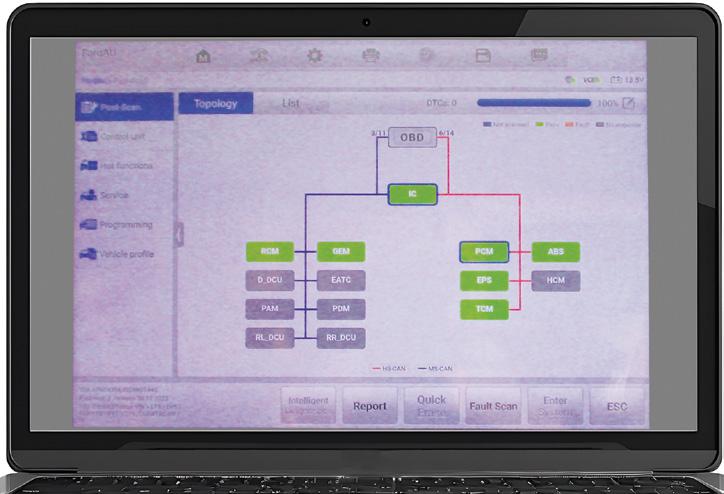
Carried out a battery test – it was OK. Carried out a full system scan and noted faults in the instrument cluster and anti-lock braking system (ABS, pic 2). Also noted that the powertrain control module (PCM) was greyed out, meaning no communication with the other units.
The integrated circuit (IC) is the gateway, communicating between the high-speed and mid-speed buses, so checked controller area network (CAN) operation using a breakout box. Confirmed waveform integrity using an oscilloscope (pic 3). Checked at PCM and confirmed a good waveform.
Decided to check the soldering done by the


previous mechanic. Had to remove a large amount of solder from pins and resolder all connections. Found two capacitors had a solder bridge – that could explain the B120460 code. Once soldering was complete, carried out continuity checks with all joints. Reinstalled the instrument cluster and was able to carry out all activation tests, focusing on the PCM. Found wiring had been taped up with duct tape. This was an old repair.
Carried out loaded power and ground testing at the PCM with terminal-retention checks –all was OK
Checked for power to the injectors and ignition coils. Found a start signal was being sent to the PCM but no earthed signal to the starter relay.
Bypassed the relay and found the starter motor was operational. Checked for a crankshaft-sensor waveform during bypassed cranking and carried out voltage tests of all pins according to ‘pin data’.
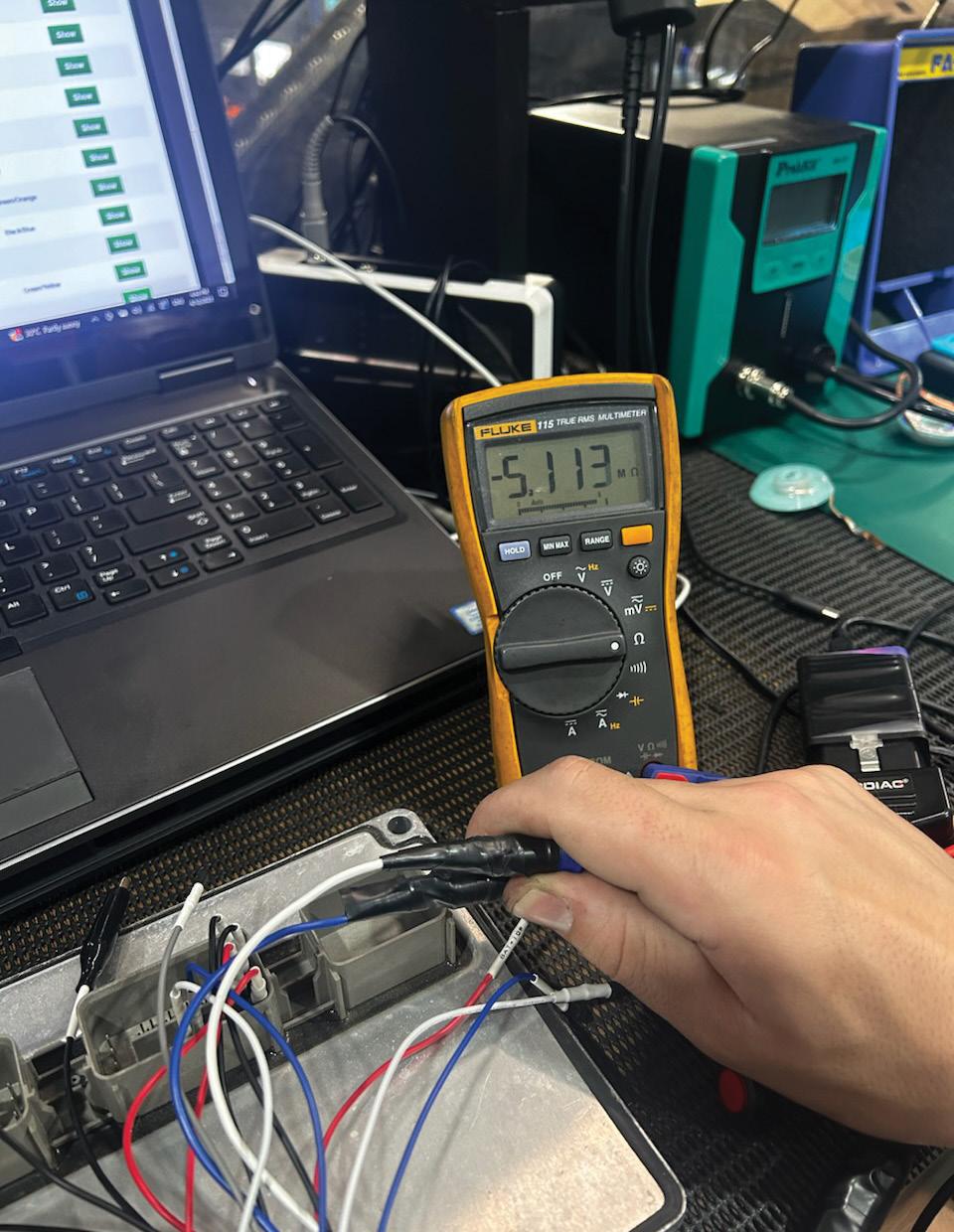
Suspected a faulty PCM, so sent the PCM and the instrument cluster to be tested. This confirmed a faulty PCM with high resistance on the CAN line – five megaohms (5MΩ, pic 4).
Fault description
Faulty PCM.
Fault solution
Testing of the instrument cluster and PCM uncovered a faulty PCM.
Sourced a second-hand PCM and linked it to the other modules. A full system scan showed the PCM was now appearing on the topology (pic 5).

Programmed the keys in the passive anti-theft system (PATS) using Forscan. The vehicle started and all codes were able to be cleared. Added an activation code to the radio and set the time, then carried out road test to confirm the repair. All was now OK.
Recommended time
Diagnostic and repair time not recorded. Repair Solution by TaT Tech Team member Mark Rabone, aka ‘Max the Mechanic’.

After a short time driving, an overtemperature warning message would appear on the centre screen and the vehicle would go into limp mode.
Problem summary
Confirmed the coolant level was correct.
As per the customer interview, a new thermostat (housing assembly) had been fitted – Mahle brand, so it was unlikely the new unit would give the same fault.
Road-tested the vehicle while monitoring the coolant temp. Within two minutes of normal driving, the coolant temperature had reached 120ºC, well above the 108ºC rating of the thermostat.
At that point, the overheating warning appeared and the vehicle went into limp mode.
When the temperature reached around 120ºC, I noted the coolant fan was on but blowing cool air. The passenger-side coolant hose was red hot but the driver-side was cold.
Turned the car off and felt the face of the radiator. It was cold all over – too cold to indicate a blocked radiator because I would expect at least a couple of fins to flow if that were the case.
Performed a full vehicle scan and retrieved a mixed bag of 64 fault codes in various modules. Cleared all fault codes to see what returned at the next overheat.
Drove the vehicle another time and it quickly brought on the fault message again.
BMW’s Digital Motor Electronics (DME) system showed fault code CD9010 – LIN message electric coolant pump missing
This external electric coolant pump is not run continuously, only when needed, but when it does run you can easily tell as you will see
water squirting into the top of the coolant-header tank through the bleed circuit. We had no coolant stream into the header tank, even while the radiator fan was on.
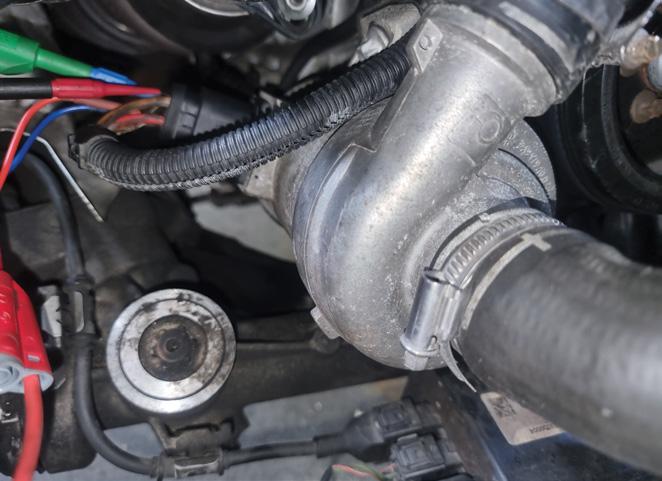
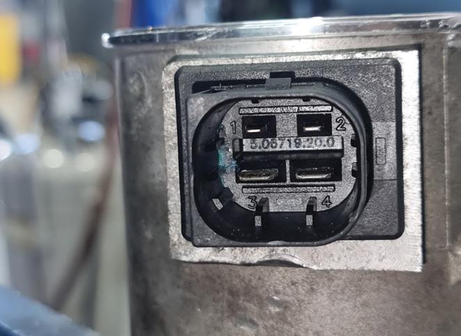
Removed the upper airbox snorkel to gain access to the water-pump connector (pic 1) and noticed a slight wetness and corrosion inside the connector (pic 2). Cleaned this away, refitted the connector and carried out a coolant-bleed procedure to force water pump to operate but the water pump still would not run.
• Coolant-bleed procedure: Ignition on, set heater to maximum and fan to low. Hold accelerator down for 10 seconds – this should command the water pump to run.
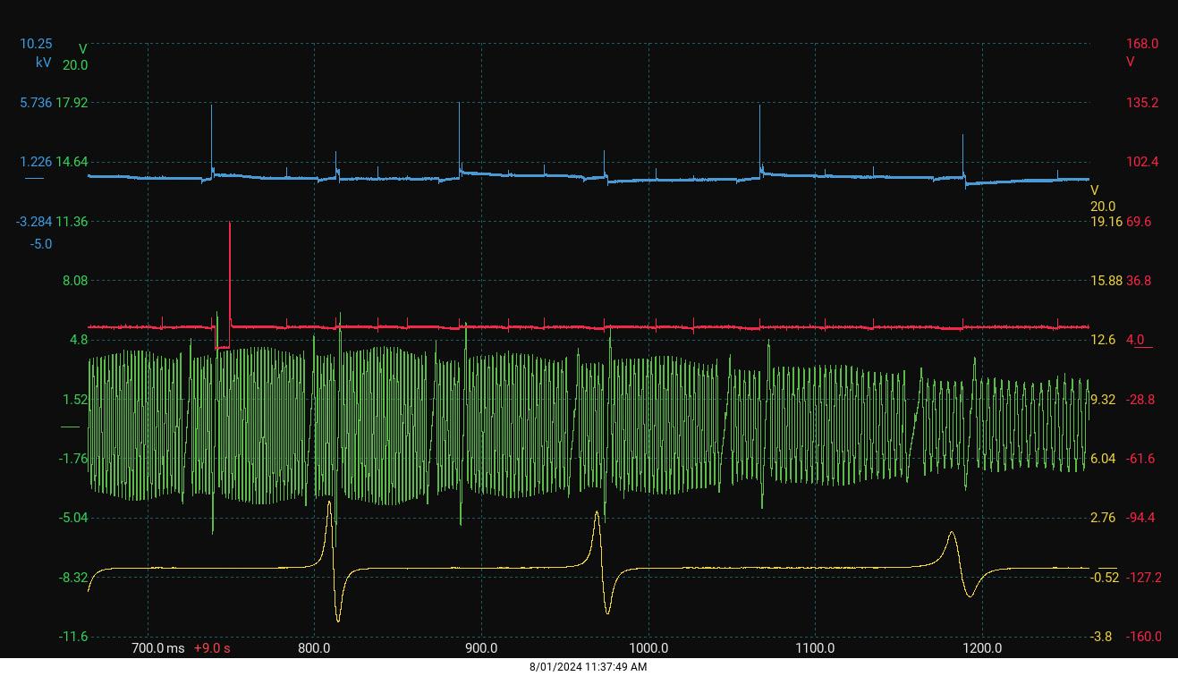
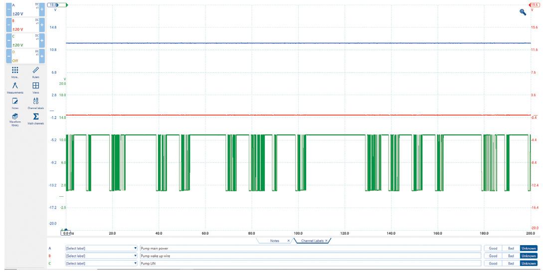
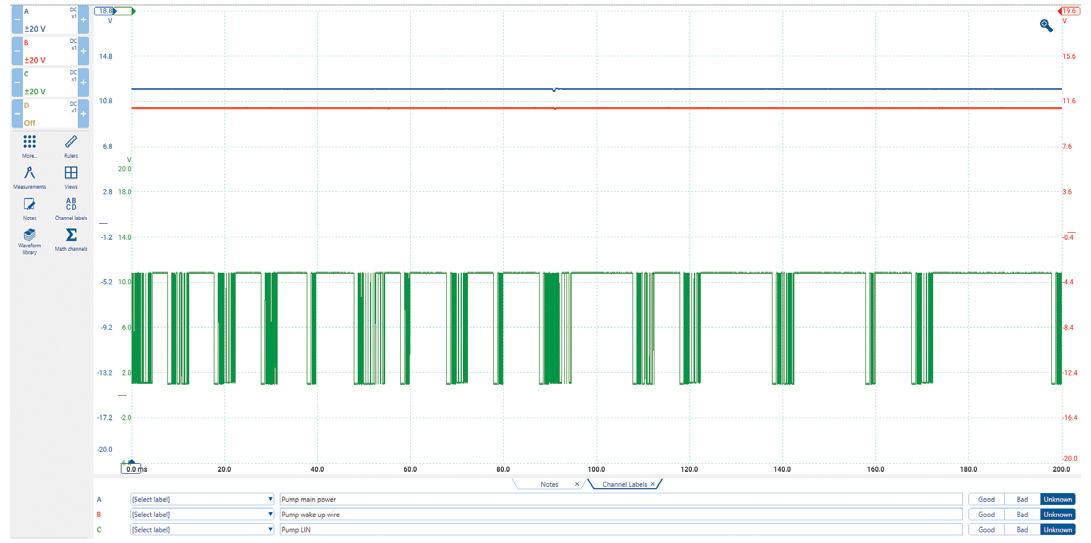
Used an oscilloscope to check the water-pump connections. Using the water-pump earth wire as the earth for all other channels, I attached blue channel 1 to water pump fused power (good), red channel 2 to water pump wake-up command (0V when off, 12V when commanded on) and green channel 3 to water pump local interconnect network (LIN) communication.
LIN communication was present as soon as I opened the door, with wake-up command off still (pic 3). Wake-up command went up to 12V when the ignition was turned on (pic 4). This command went off after a period of time but engaging the bleed procedure brought the wake-up command back to 12V.
The water pump seemed to have everything it needed to run but it wouldn’t. To erase any doubt, I unplugged the waterpump connector and noted no change in the rhythm of the LIN communication.
This suggested it was all coming from the DME with no response from the water pump. I then used an incandescent test light on water-pump connector power and ground to ensure the circuit could flow under load.
The electric water pump was not operating.
Fitted a new electric waterpump assembly (Pierburg is original equipment).
Diagnostic time was one and a half hours, taking into account preparation and research.
Repair time was one and a half hours, taking into account the location of parts and carrying out the repair to a tested outcome.
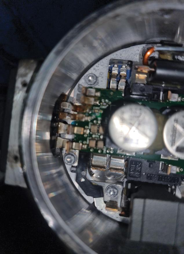
Disassembly of the water pump after the repair showed the internal shaft seal had leaked, allowing coolant onto the circuit board (pic 5). This was the source of moisture that I first saw in the connector. Repair Solution by TaT Tech Team member Brendan Sorensen.
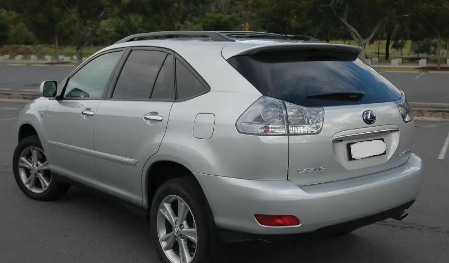
Customer complaint
The vehicle had just stopped while driving and now would not go into ‘Ready’ mode.
Problem summary
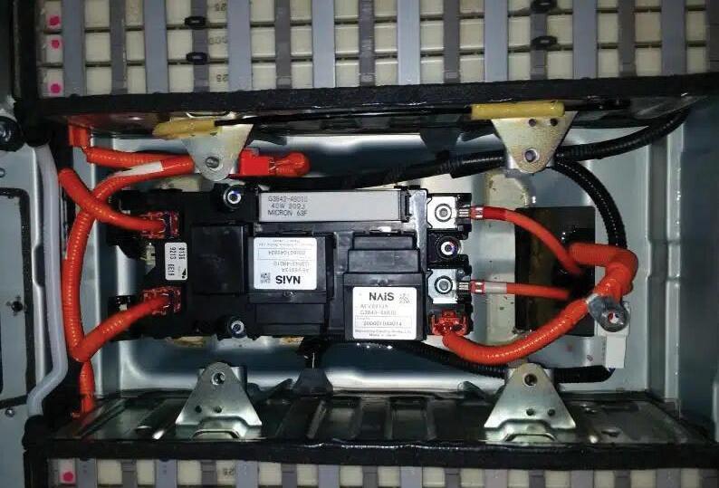
Confirmed the vehicle (pic 1) wouldn’t go into Ready mode. Everything else seemed to be working (lights, dash warnings etc).
Diagnostic sequence
Performed a full system scan but could not communicate with either the ECU or the hybrid control module.
Tested all fuses and found fuse ‘IGCT2’ was blown. Fitted a new fuse and retested but the fuse blew when the vehicle ignition was turned on.
Hooked up a short light and, when switching the ignition on (i.e. Ready mode), the short light illuminated brightly, indicating power on one side of the fuse and earth on the other.
A good inspection of the main contactors, pre-charge relay and resistors showed no obvious issues. After unplugging both ECU and the hybrid control module the short light was still fully illuminated. The short was still present.
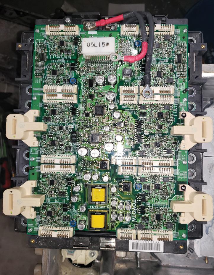
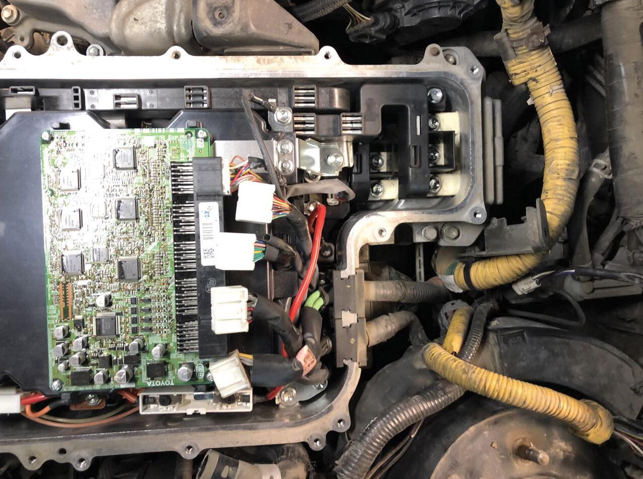
After removing the inverter cover (with PPE equipment on), I detected a strong burnt electronics smell coming from inside the inverter (pic 2 and 3).

After unplugging the low-voltage connectors, the short light went out, indicating the short was no longer present.
An insulated gate bipolar transistor (IGBT) had failed and shorted out the circuit board of the inverter.
The IGBTs are used to change the DC power supply of the high-voltage battery into the AC power required to run both motor generators (MG1 and MG2).
Sourced and fitted a second-hand inverter. No programming was required (pic 4).
Cleared the fault codes and the vehicle now went into Ready mode.
Diagnostic time was three hours, taking into account preparation and research. Repair time was two hours, taking into account the location of parts and carrying out the repair to a tested outcome.
Fully testing the motor/s is strongly recommend when performing any repairs or replacing an inverter on any hybrid or electric vehicle (EV). If there are issues with the motor/s, this may cause an inverter failure. This preventative action could possibly prevent costly repairs that could reoccur due to issues with a motor/s.
Repair Solution by TaT Tech Team member Jeff Smit.


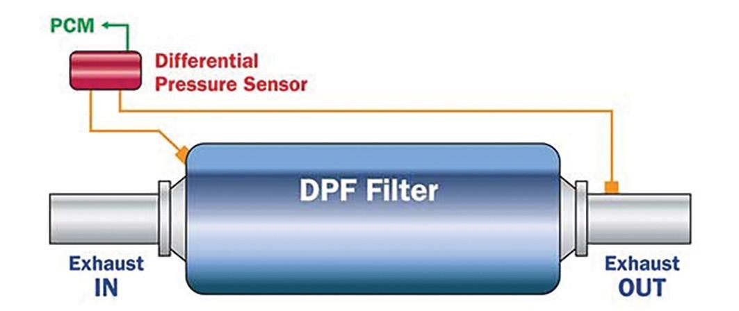
The exhaust-pressure sensor (EPS) is a pressuredifferential sensor required by the ECU to monitor the restriction level of the diesel particulate filter (DPF) so the ECU can perform levels of DPF-regeneration procedures depending on how much soot has been stored in the filter.
What does this mean?
Most (but not all) common-rail diesel (CRD) vehicles are fitted with a DPF to filter/store soot and ash – two of the biproducts of combustion and reported as harmful to humans and the environment – before they are released from the exhaust into the atmosphere.
When the level of these stored products start to restrict the exhaust flow through the DPF, the ECU requests elimination of the restriction by temporarily increasing the internal temperature of the DPF and allowing the soot to alter its structure when reacting with the extreme heat and the DPF internal material structure.
During the reaction, the solid soot mass is combusted and released in a gaseous form that is much lower in emissions levels.
Note: It is important to note that unlike soot, the ash quantity trapped in the DPF cannot be combusted and tends to be stored internally and eventually becomes problematic. The ash is generally increased in quantity when engine oil is burnt in greater volumes than expected.
Regeneration process
The pressure difference between ‘exhaust-in’ on the DPF and ‘exhaust out’ on the DPF, monitored by the EPS, is utilised by the ECU to select and perform a DPF regeneration procedure.
1. Passive regeneration
This increased quantity of fuel occurs automatically with no warninglight indication displayed.
2. Active regeneration
When the soot loading reaches approximately 45 per cent, as indicated by the signal from the EPS to the ECU, an increased quantity of fuel is commanded by the ECU to enter the DPF when the conditions are suitable.

Note: If the DPF remains partially restricted after these regeneration processes, then the ECU will demand a forced or manual regeneration procedure to take place. This requires the use of a suitable scanner and must not be carried out in enclosed premises
EPS/pressure-differential valve – plausibility test
Note: When a fault in the DPF/EPS system occurs, it is important to correctly determine which component (if any) is at fault due to the generally high cost of a new DPF.
EPS plausibility test using a multimeter
A typical expected output signal voltage for an EPS signal on a DPF system that is unrestricted is generally approximately 0.5-0.7V at idle.
Note: A partially restricted DPF may increase this reading a small amount but requires further tests.
At full load (approximately 2000RPM is acceptable) on an unrestricted DPF, the expected output-signal voltage would have a typical reading of approximately 1.6V.
Note: A restricted DPF would generally indicate an increased voltage that could be as high as 4.0V on a DPF that is excessively restricted.
Testing the EPS with a suitable scanner
A scanner can quickly allow for a variation of monitoring signals, typically testing soot mass in grams.
Example:
• Typical unrestricted DPF idle reading = 1.41g.
• A soot-mass of 99g would require DPF replacement.
• A typical restricted DPF may indicate around 22g soot mass.
Pressure reading
A typical EPS scanner reading for pressure may be approximately 6-10 hectopascals (hPa) at idle. This pressure should not exceed 100hPa at Idle.
Note: A ‘restricted DPF’ during road-test load conditions may indicate a reading of approximately 300-350hPa, which would require replacement of the DPF to rectify driveability concerns.
A suitable oscilloscope can also be used to investigate the output signal.
Note: On some later EPS units, the output signal may vary to a conventional EPS due to the piezo signal. These quick-reacting type sensors display the internal DPF pressure turbulence and the signal may be confused with a signal that has been affected by external electrical noise.
The Premier Auto Trade sensor range includes EPSs from the world’s leading manufacturers covering more than 4.9 million vehicle applications in Australia and New Zealand.
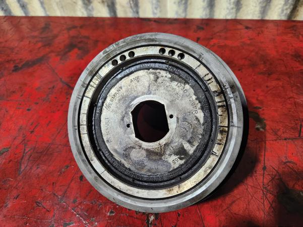
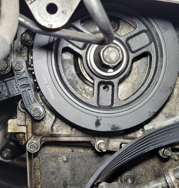
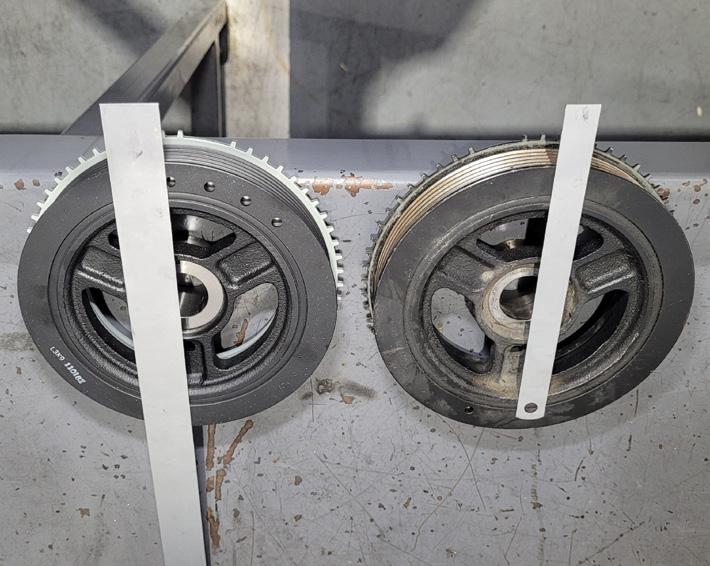
This 2020 Nissan Navara NP300 80,181km on clock came in a belt-squealing noise at the front of the engine. It was particularly noticeable with the a/c engaged. Initial inspection showed the belts were dry but not visibly worn. Traced the noise using a stethoscope to either the a/c compressor or the harmonic balancer, though pinpointing it from above proved difficult. On the hoist, spraying silicone on the belt altered the noise but didn’t eliminate it.
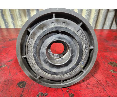
Removing the belts allowed a closer look, revealing the
outer pulley of the harmonic balancer could easily flex away from the hub. Despite no visible damage, the noise was attributed to a factory design flaw: excessively thick rubber combined with two thin flange plates securing the balancer to the crankshaft.
Fitting a new genuine harmonic balancer resolved the issue. The engine also sounded less ‘knocky’ at idle and low engine speeds after the repair.
Diagnostic time for this job was 90 minutes and repair time 3.5 hours.
Ian Richards Aitkenvale Auto & Dyno AITKENVALE, QLD
Tips for TaT
We are experiencing all kinds of sounds and failures with these NP300 balancers, with the most common being deep knocking you would swear was internal to the engine.
Protex recognises different vehicles and driving conditions demand specific braking solutions.
With more than two decades of experience in the automotive industry, Protex takes pride in offering a comprehensive product range tailored to suit various applications.
As a specialist brake brand, Protex offers full braking solutions across all key product groups. Well-known for rotors and pads, the brand also offers a large range of other products including hydraulics, drums, shoes and all the components in between. This assortment of brake products and comprehensive range ensures Protex offers a full braking solution for a variety of vehicles and driving conditions.
Protex’s comprehensive product range is stringently tested so technicians and owners can have confidence they are getting topperforming products to fit even less common vehicles.
Pads: Protex pads feature an advanced ceramic formulation to helps extend pad and rotor life and, more importantly, minimise dust and noise. Protex pads consist of materials formulated to ensure optimal friction and heat resistance, resulting in better brake response and longer lasting pads.
Rotors: Protex rotors feature the brand’s Ultracoat Z360 protective enviro coating
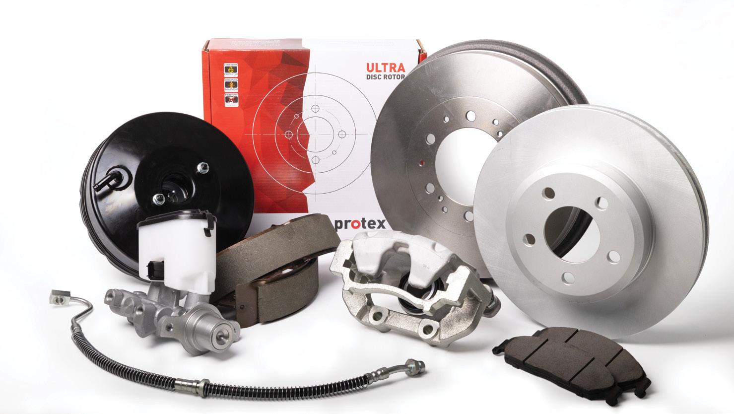
and are precision manufactured for even wear, reduced noise and enhanced heat dissipation.
Hydraulics: The Protex range is available to suit most cars on Australian roads, including repair kits and components, master, slave and wheel cylinders, pistons and hoses.
Drums: Protex drums are ground-finished and balanced for smooth braking, precision drilled and machined for accurate fit.
Shoes: Premium ceramic, non-asbestos organic (NAO) and semi-metallic materials for a stable coefficient of friction and radius ground for a precision fit. This comprehensive range includes front, rear and
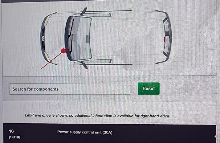
This 2009 Volkswagen Caddy came in with multiple lights out: right-hand (RH) headlight, RH parker, RH high beam and the fog lamps.
There were codes in the central electrics module for all of the lights out, as well as the following code:
• 00927 – Terminal 30 (right) 0011 open circuit - intermittent.
Although the vehicle had a blown RH lowbeam globe, replacing it didn’t help. It still wouldn’t operate.
Given there were a lot of lights out on the right side of the vehicle and a code for terminal 30, I decided it was most likely a blown fuse or maybe even a module fault.
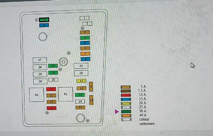
I opened HaynesPro Data and got the fuses and relay locations. When I checked all the
fuses and found none were blown, I started to scratch my head, thinking maybe it was a module.
Back to Haynes to figure out which ones were module related. I went to go over the fuses one more time and removed the ones located for modules.
I was shocked but happy when I found this cooked-up fuse. It was tucked in behind another fuse up the back and I hadn’t noticed it when I’d performed a visual inspection.
I’ve never seen a fuse this cooked up that checked OK with the test light. I’m sure a lot of auto electricians have but this was my first time.
Diagnostic and repair time not provided.
Anthony Tydd BENDIGO, VIC
parking-brake applications for passenger and 4WD vehicles for Australian fitments.
Calipers: Protex offers an extensive range of replacement calipers and subcomponents that are engineered and tested to meet OE fit, form and function.
Protex stands behind its product quality with a minimum 12 months/20,000km warranty. Finding Protex brake products couldn’t be easier with its online part finder. Protex’s part finder is fully catalogued and regularly updated to help users find the part they need. Go to protexparts.com.au for more information on the comprehensive Protex range.
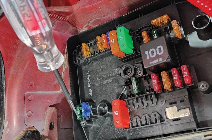
Here a couple of good reminders to take from this situation, which can often occur on VWs due to the fuse holder’s poor female terminal tension.
1. If the burnt leg was on the load side, you will see good voltage on both fuse test points as you have here.
However, if the burnt leg was on the control side, you will see the results of a voltage drop at both fuse test points, provided you have loaded the circuit by having the load operating or by using an incandescent test light of decent wattage on the fuse test points (the LED test light shown may not load the circuit enough, giving no voltage drop and falsely still showing a good 12.4V).
2. It’s a good habit to give your test light a little wiggle while testing fuses. This wobbles the fuse and can sometimes uncover bad female terminal tension.
This 2008 Mazda CX-7 with 187,000km on the odometer arrived on a tow truck with the owner reporting hard starting, a rough idle and no power.
Recent work by two other mechanics included a new turbocharger and cylinderhead gasket, though the owner wasn’t sure if the issue existed before these repairs. Initial checks showed fluids were okay and a self-test revealed no DTCs. Cranking the engine revealed a long crank period before starting, after which the engine stalled. After three cold starts the engine idled poorly, with black smoke pouring from the tailpipe under acceleration.
Attempted a road test but it proved unsafe due to the lack of power. Parameter ID (PID) data looked normal except for a mismatch between actual and commanded valve timing – actual valve timing was 15 degrees while commanded was minus 15 degrees. Given the vehicle’s history and this PID anomaly, the first check was the mechanical valve timing.
This engine’s crank and cam timing require special locking tools as there’s no crank keyway. Confirmed the valve timing was correct but the crankshaft position (CKP) sensor pick-up was misaligned, sitting between two teeth on the tone wheel.
Realigning the crank pulley improved the valve-timing PIDs slightly but did not resolve the issue.
The repair manual specified the CKP should align with the 20th tooth counter-clockwise from the gap – this problem vehicle’s sensor, contrastingly, was aligned with the 15th tooth.
Further inspection revealed no signs of rotation or prior removal of the tone wheel, which is press-fitted onto the crank pulley. Suspecting a modified or incorrect part, ordered a new crank pulley, crank bolt and
diamond washers and compared them on the bench.
Fitting the new crank pulley resolved the issues entirely. Valve-timing PIDs now read zero degrees plus-minus (±) one degree at idle and the vehicle performed normally. The incorrect crank pulley was identified as the root cause.
Diagnostic time for this job was approximately three to four hours and repair time 90 minutes.
Nicholas Leitch Grand Prix Mazda Caboolture D’AGUILAR, QLD

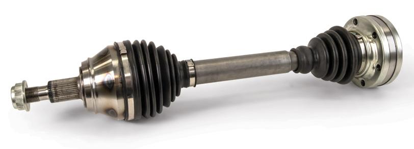
The driveline is a vital system in any vehicle, responsible for transferring power from the engine to the wheels.
While designed for durability, even the toughest components can wear down over time. Early identification of driveline issues is crucial to prevent costly repairs and ensure vehicles stay on the road. Here’s what to look for.
Driveshaft imbalance: Unbalanced driveshafts can cause significant vibrations, particularly at high speeds. BW provides precision-balanced driveshafts and alignment services designed to maintain performance after repairs.
Centre-bearing failure: A worn centre bearing can worsen vibrations. BW’s range includes reliable centre bearings designed for optimal performance, helping to stabilise and reduce vibration while ensuring a smoother ride.
2. Identifying CV joint failures
Signs of trouble
Clicking or popping sounds: These noises during turns often signal a failing CV joint. BW stocks high-performance CV joints designed to enhance flexibility and power transmission, preventing further issues. Inspecting the boot: Cracked or torn CV boots allow contaminants to enter, accelerating wear. Regularly checking and replacing CV boots with BW’s quality options can ensure longevity.
3. Leaks from the transmission or differential
Fluid leaks: Fluid leaks can lead to heat build-up and rapid wear. BW’s comprehensive range of seals and gaskets are designed to help maintain fluid integrity, ensuring proper lubrication and reducing the risk of damage.

Fluid condition: Contaminated or burntsmelling fluid indicates internal damage. BW provides high-quality fluids and additives designed to keep systems clean and functioning optimally.
4. Clunking and jerking during acceleration
Potential causes
Differential wear: Excessive backlash in the differential can cause clunking. BW offers differential parts and gear sets designed to ensure precise adjustments, eliminate noise and enhance driveline stability.
Worn mounts: Cracked or worn mounts can lead to clunking during acceleration. BW’s selection of engine and transmission mounts
is designed to help absorb movement and secure components effectively.
5. Preventative maintenance
Regular maintenance is key to prolonging driveline component life
Lubrication: Ensure U-joints and CV joints are regularly lubricated. BW provides a range of high-performance lubricants designed to protect components from wear.
Early detection: Be vigilant about vibrations, clunking or leaks. BW’s knowledgeable team and quality products can help mechanics address issues before they escalate into costly repairs.
The BW advantage
BW offers an extensive range of driveline components specifically designed for the Australian and New Zealand markets, ensuring OE quality that stabilises and supports driveline systems while reducing vibrations. With a minimum warranty of two years or 40,000km, you can trust BW products are built to last.
Driveline problems can quickly escalate if ignored. Regular inspections and proper maintenance with BW parts can keep a vehicle running smoothly and efficiently.


Following on from part one of this series of articles on electric vehicles (EVs), this instalment continues to explore the magnitude of the voltages and amperages used in modern full EVs (FEVs).
We aim to approach this from a Mechanic’s Point of View (MPOV) and link the concepts to the existing knowledge pool of vehicle repair and servicing. By grounding this discussion in familiar examples, we’ll break down the significance of using high voltages in EVs.
Let’s consider the example of heating the car’s interior – a process significantly different in an EV compared to traditional internal combustion engine (ICE) vehicle.
How does an EV heat the cabin?
In an EV, engineers commonly utilise heat pumps (similar to reversecycle air-conditioning systems) and heat generated from the battery stack during charging to warm the cabin.
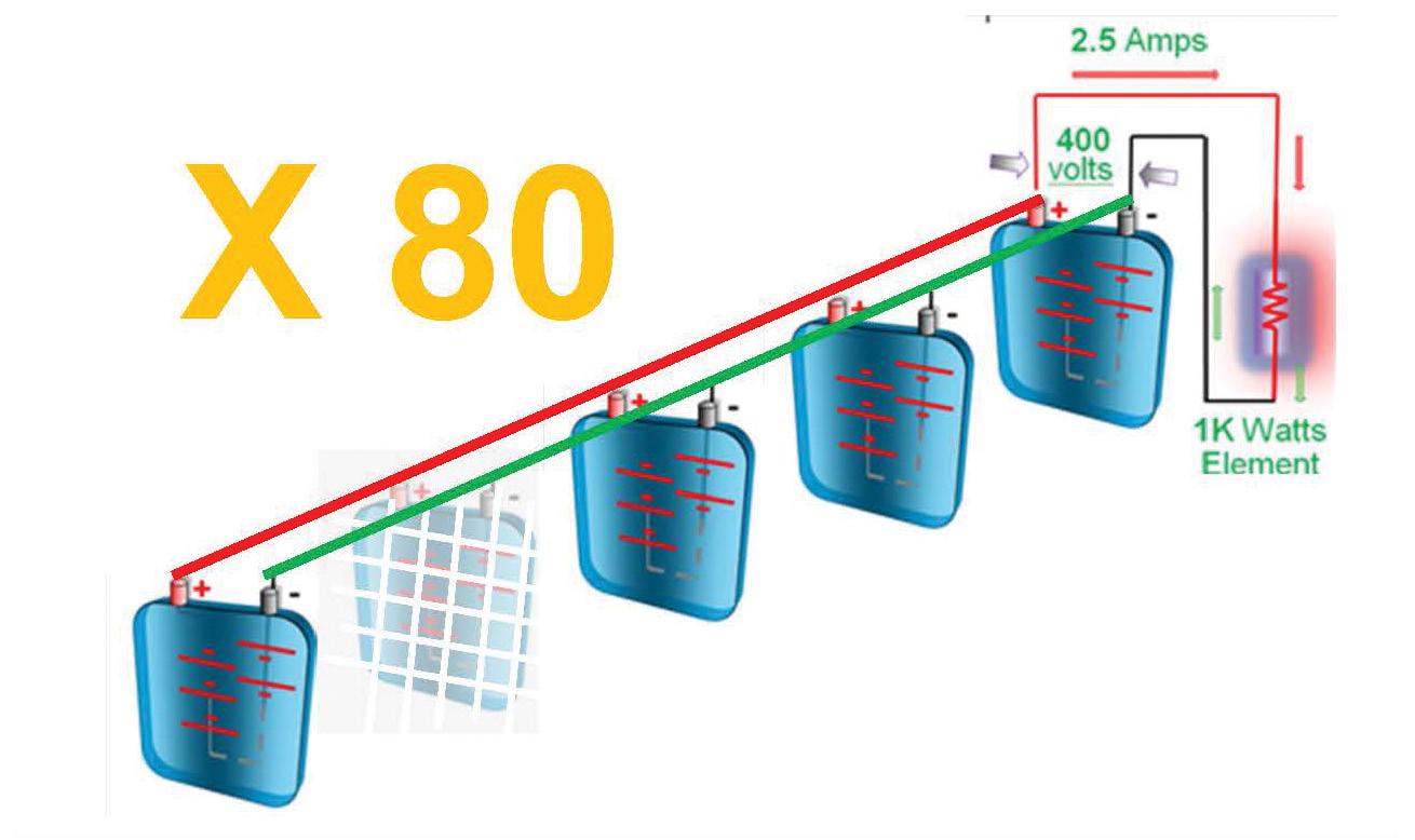
For the purpose of this article, however, we’ll assume the only heat source is a hypothetical single resistive heating element rated at one kilowatt (kW). This element is comparable to a single-bar radiator heater found in homes but powered by a 12.8V battery, not 240V.
We’ll examine three scenarios:
1. The current drawn by the resistive heating element in an oxygen (O2) sensor (powered by a 12.8V battery).
2. The current drawn by a hypothetical 1kW resistive heating element used to warm an EV cabin (powered by a 12.8V battery).
3. The current drawn by the same 1kW heating element when the battery voltage is increased to 400V.
By comparing these scenarios, we’ll highlight the practical advantages of using high-voltage systems in EVs.
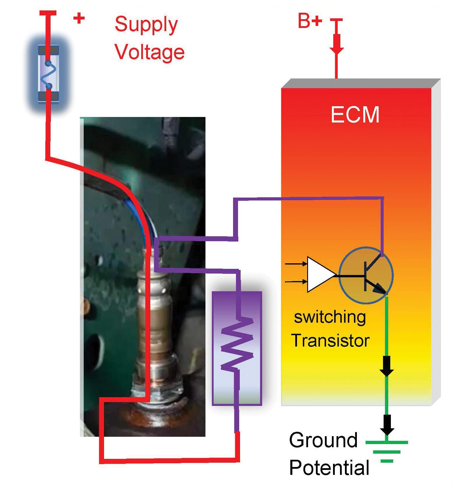
O2 sensors rely on exhaust gases to heat their sensing elements but heater circuits embedded in the sensor housing speed up this process. Modern O2-sensor heaters typically have a resistance of 13.5Ω, switched on/off via transistor (pic 1).
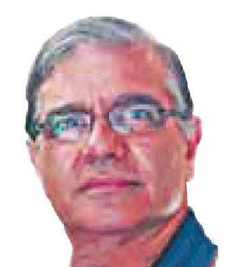
Using Ohm’s law, we can calculate the current flowing through the heater circuit (transistor grounding and not PWM – pic 2):
I = V / R
I = 12.8V / 13.5Ω ≈ 1A
The power consumed by the O2 sensor’s heater element is:
W = I × V
W = 1A × 12.8V = 12.8W
At 12.8W, this power draw is similar to that of an automotive park light or small electric motor. This serves as a reference point for comparing the much larger power requirements of an EV cabin heater.
Now let’s calculate the current draw of a 1kW heating element, which would be required to heat an EV cabin:
I = P / V
I = 1000W / 12.8V ≈ 78A
This 78A current draw is approximately 78 times greater than that of the O2 sensor’s heater element. It’s also comparable to the current drawn by a modern starter motor during cranking (pic 3).
To handle such high current, the wiring would need to be as thick as the main feed cable running from the battery to the starter motor – significantly larger than the wires used for an O2-sensor heater circuit.
Clearly, drawing such high current is impractical, which leads us to the need for higher voltages.

To reduce the excessive current draw while maintaining the same power output, engineers use higher voltages.
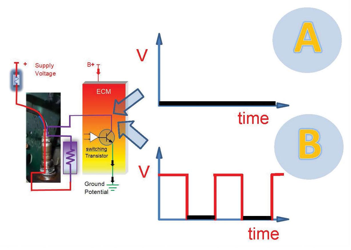
Let’s calculate the current draw of the same 1kW heating element but now powered by a 400V battery:
I = P / V
I = 1000 W / 400V = 2.5A
At 400V, the current draw is reduced to just 2.5A while still delivering 1kW of power. This dramatic reduction in current significantly decreases the required wire gauge, making the system far more efficient and practical.
We’ve now compared the current draw and wiring requirements of:
• The O2-sensor heater circuit (12.8W), which draws about 1A at 12.8V (pic 1).
• A hypothetical 1kW EV cabin-heater element, which draws 78A at 12.8V (pic 3).
• The same 1kW heater, which draws just 2.5A at 400V (pic 4).
From our MPOV, this demonstrates the importance of high voltages in EVs. By increasing the voltage to 400V, the current draw is significantly reduced, allowing the system to operate efficiently without requiring excessively large wiring.
If a battery were capable of supplying 1kW of power for one hour, it would have a rating of one kilowatt-hour (kWh). By comparison, most modern EV batteries have a capacity of 80kWh, which is 80 times greater than our hypothetical example (pic 5).
4
5
We’ve examined the role of high voltages in EVs but additional questions arise:
• How is the 12.8V battery in EVs kept charged without an alternator?
• How is the DC (400V) from the battery converted to alternating current (AC) for traction motors?
We’ll explore these topics in our next article.
This article is intended to illustrate the why and how of EVs, supported by basic theory. However, readers must be aware that contact with high voltages is potentially fatal.
If you plan to measure high voltages, you must observe all safety precautions, such as using CAT IV-rated digital multimeters and insulated gloves. These tasks should only be attempted after completing industrystandard training. 3
The Australian Automotive Aftermarket Association (AAAA) has welcomed the Federal Government’s launch of the DRIVEN Charger Rebate Stream, a $40 million initiative aimed at increasing electricvehicle (EV) charging infrastructure at automotive dealerships and independent EV repairers across Australia.
The grant, part of the broader DRIVEN Program, offers up to $2500 per eligible smart EV charger installed, with a maximum rebate of $20,000 per site. The program is designed to ensure widespread adoption, including in regional and remote areas, and will run until April 2028.
‘This grant program is a game-changer for independent auto repairers,’ said AAAA CEO Stuart Charity. ‘The AAAA has long called for support to help small and medium automotive businesses play a leading role in Australia’s EV transition.
‘The DRIVEN Charger Rebate Stream directly addresses key financial barriers that often prevent independent repairers from investing in EV-charging infrastructure.’
The AAAA highlighted the program’s critical role in ensuring the independent sector remains competitive and prepared to service Australia’s growing fleet of EVs.
‘The EV transition isn’t just about selling more low-emission vehicles – it’s about creating an ecosystem that supports EV owners everywhere, from metro areas to the most remote parts of the country,’ said Charity. ‘This initiative helps level the playing
field for independent repairers, ensuring they can provide the same high-quality service as larger dealerships.’
Charity also emphasised the importance of the grant program in addressing Australia’s ambitious decarbonisation targets.
‘Expanding EV charging infrastructure is vital in building consumer confidence in EVs, particularly in regional and remote areas,’ he said. ‘Programs like this demonstrate the government’s recognition of the pivotal role our industry plays in decarbonising transport and meeting net-zero goals.’
While welcoming the initiative, the AAAA called for continued collaboration with the Federal Government to address other critical infrastructure and policy needs for the independent automotive-repair sector.
‘We see this as an important step forward, but there’s still work to be done,’ said Charity. ‘We urge the Skills Minister, the Hon. Andrew Giles MP, to lead efforts to address in-service training and skills mandates.
‘Without a cohesive national approach,

fragmented state-based regulations will complicate operations for repairers –particularly larger groups working across multiple states – and worsen the existing skills shortage.
‘Notably, both New South Wales and Western Australia are actively considering state-specific regulations, further highlighting the need for national leadership.’
The AAAA also welcomed the government’s recent incentive program for apprentices but called for its extension beyond housingconstruction trades.
‘If the goal is to encourage more Australians to pursue trade careers, support for automotive apprenticeships is a clear winner,’ said Charity. ‘We need to see policy initiatives that reflect the critical role of the automotive sector in the economy and its importance in supporting the transition to EVs.
‘The skills shortage is one of the most significant challenges facing our industry and targeted apprenticeship incentives could make a world of difference.’
The AAAA encourages all eligible businesses to apply for the DRIVEN Charger Rebate Stream. For more information go to business.gov.au/grants-and-programs/driven-charger-rebate-stream
Workshop owners, did you know there’s a government rebate program that could help cover all or the majority of costs for the supply and installation of an electric vehicle (EV) charger at your business?
The DRIVEN Charger Rebate Stream is part of a national government initiative to assist automotive businesses in preparing for the growing EV market while supporting Australia’s transition to a more sustainable future. What’s on offer?
• Up to $2000 per installed seven-kilowatt (kW) AC charger.
• Up to $2500 for AC chargers with 11-22kW capability and DC chargers with up to 50kW capability.
• A maximum rebate per site of $20,000.

A 22kW AC charger requires a three-phase connection and can typically provide up to 120km of EV range per hour of charging. While most current EVs are limited to 11kW AC charging, models with 22kW capacity are expected to become more widely available in the future.
Installing a three-phase charger with higher capacity ensures your workshop is prepared for these advancements. There are many three-phase 22kW options available that can be supplied and installed within the $2500 budget if a workshop already has a threephase supply coming into the building. Eligibility requirements
To qualify as an automotive-repair business, you’ll need:
1. A registered business in the automotive repair or sales sector.
2. Membership details and the full name of a staff member holding an Australian
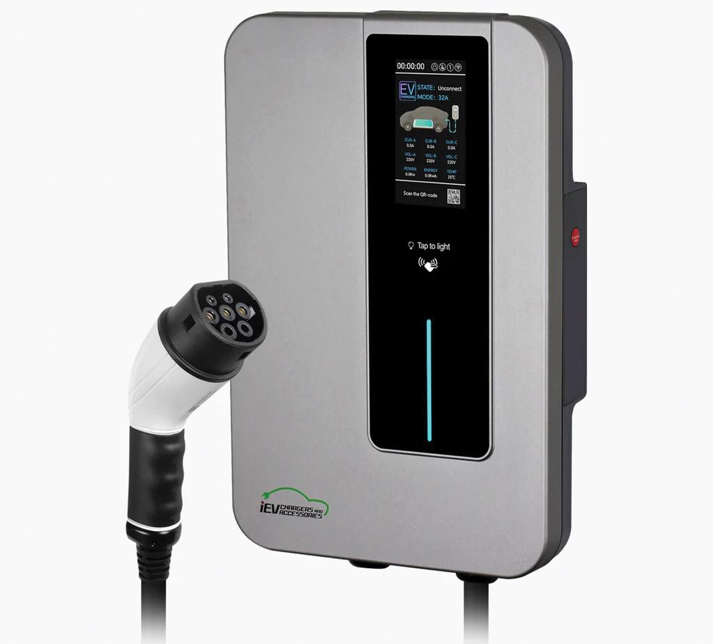
Automotive Service and Repair Authority (AASRA) membership with the EV credentials account upgrade. You’ll also need to keep receipts and submit proof of installation to claim the rebate. Applications close on April 30 each financial year until 2028 or earlier if funding is exhausted.
Keep an eye out for our upcoming High Voltage Battery Testing webinar, where we’ll showcase how having an EV charger is essential for tasks such as battery-health reports on certain models.
For more details or to apply for the rebate, go to business.gov.au

As a follow-up to our Technical Spotlight on treatments, chemicals and additives, here’s a case study of a Toyota Kluger that really lacked TLC but was brought back to life.
car
Toyota Kluger GSU45R, 2GR-FE 3.5-litre V6, 226,000km on the clock.
A customer contacted me for over-thephone advice regarding their Toyota Kluger’s ongoing problems. As they lived a considerable distance away, I was happy to offer advice remotely.
The vehicle’s issues included occasional smoke from the exhaust when stopped at traffic lights, an engine rattle and oil consumption of 100mL per 100km. The customer also mentioned the rattle sounded like timing-chain noise.
Otherwise, the car was running OK but it clearly needed some attention.
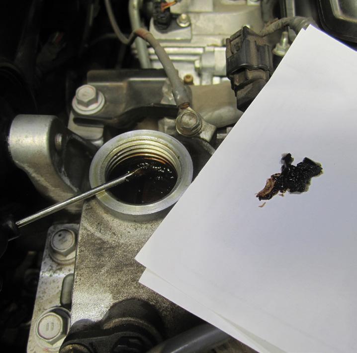
My first question during the phone call was about the vehicle’s service history. The customer admitted it was poor. I asked about the oil colour and whether there was sludge under the oil cap or in the filler hole. Photos sent by the customer confirmed sludge and poor oil condition.
I explained that sludge in these 2GR-FE engines can cause significant issues, including blocked oil passages, rockercover vents or positive crankcase ventilation (PCV) system problems, potentially causing the symptoms described. I emphasised that diagnostics were necessary to assess the situation accurately and avoid false hope.
The car arrived for inspection a few weeks later. A road test revealed no immediate smoke or rattles. Carried out a series of basic tests, checks and visual inspections, including fluid levels, lights, safety items and tyre pressures. A full diagnostic scan revealed no DTCs. However, the oil level was low, the oil quality was terrible and sludge was present under the oil cap and in the oil-filler hole (pic 1).
Being familiar with sludge-related issues in these engines, I knew the variable valve-timing (VVTi) system, PCV system and rocker-cover ventilation could all be affected. Performed a relative compression test using a Pico scope (pic 2), revealing even compression with a peak of 96.44A.
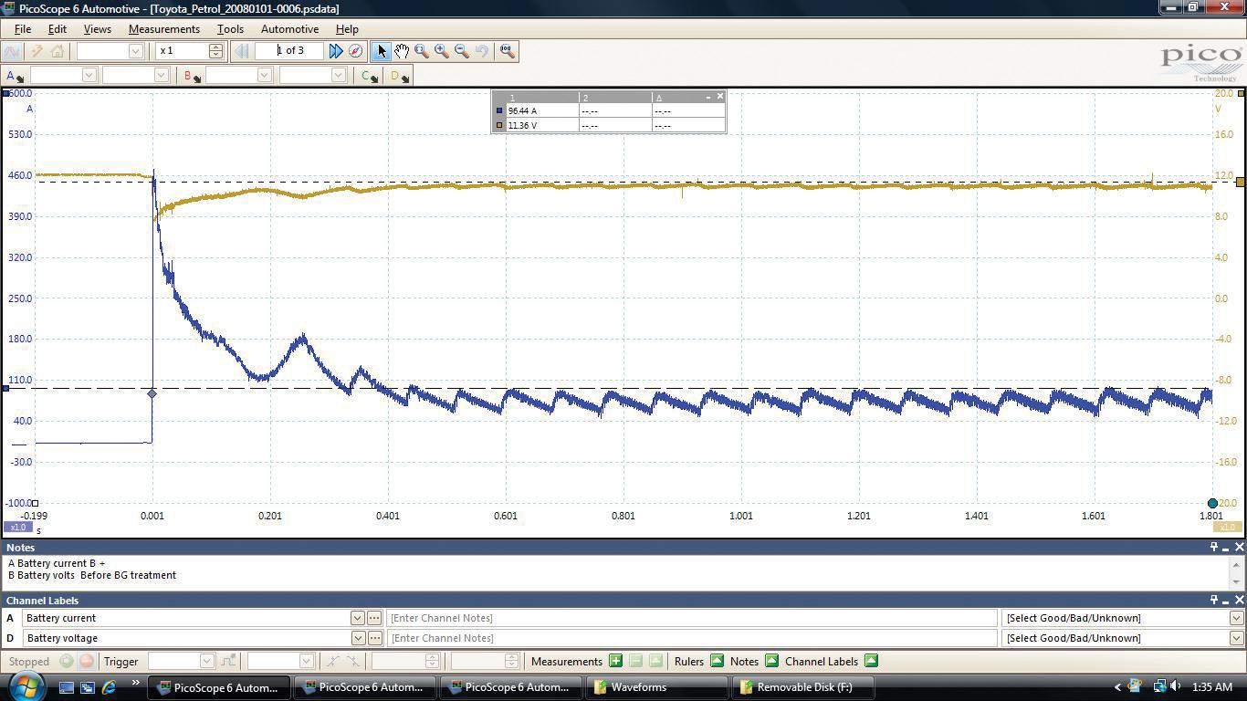
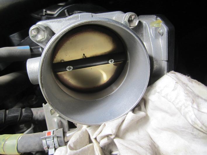
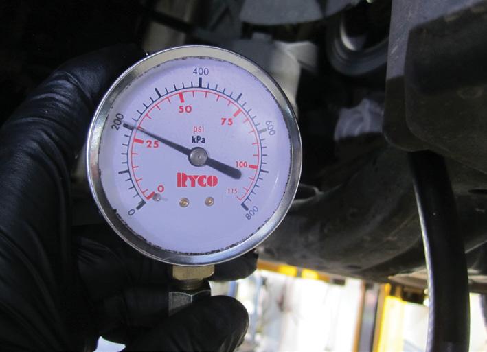
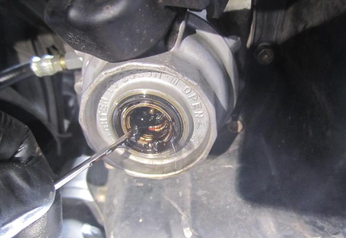
The PCV valve appeared functional but showed signs of oil ingress. Similarly, the rocker-cover vent hoses were not blocked but had an oily residue. Cleaned a dirty throttle body (pic 3) and inspected and cleaned the air cleaner and mass air flow (MAF) sensor.
Based on these findings, I believed severe sludge in the PCV and rocker-cover vent systems was causing oil ingestion, leading to the occasional smoke and rattle symptoms that had been reported by the customer. I also believed this vehicle would be a very good candidate for a BG Dynamic Engine Restoration Treatment.
TaT Technical Director Brendan Sorensen has a brilliant YouTube video showing a similar problem in a Toyota Aurion. In the video, he removes the rocker covers to do a before and after-treatment comparison and it’s absolutely mind blowing how the sludge gets completely dissolved and disappears without affecting any of the oiling system in the engine, leaving a valve train that looks like new.
Contacted the customer and gave them the results of my findings. I suggested performing a BG Dynamic Engine Restoration Treatment while noting the risks involved and highlighting it would not necessarily be a magic wand. The customer agreed to the treatment.
Before starting the treatment , I installed a manual oil-pressure gauge (pic 4) to monitor real-time oil pressure by removing the oilpressure switch. The oil-warning light did not illuminate in either key-on engine-off (KOEO) or key-on engine-running (KOER) conditions, a potential issue I noted for future attention. Brought the engine up to operating temperature and started the restoration process:
1. Drained the engine oil and replaced the filter. Observed sludge in the oil-filter housing (pic 5).
2. Added the first BG product and ran the engine at approximately 3000RPM for 45 minutes while monitoring live data and oil pressure. Next, drained the oil and replaced the filter.
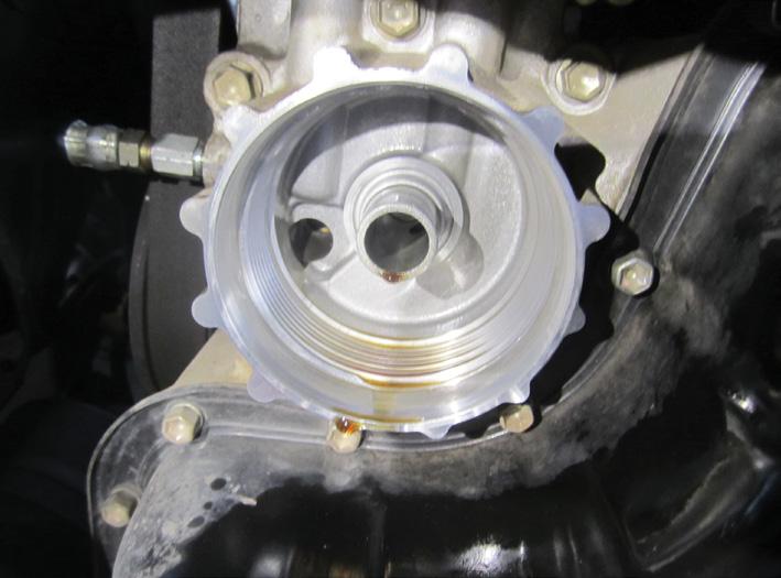
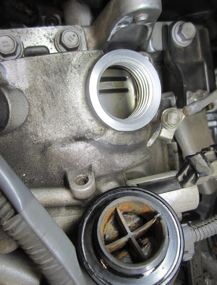
3. Added the second BG product and ran the engine again at 3000RPM for 20 minutes while monitoring as before. Afterwards, drained the sump and replaced the filter. The oil-filter housing now looked clean and silver (pic 6).
Next, added fresh oil, BG Advanced Formula MOA Oil Treatment and BG 44K Fuel Treatment to complete the process. After this the sludge was completely gone and the engine internals, including the oilcap area, were visibly clean (pic 7).
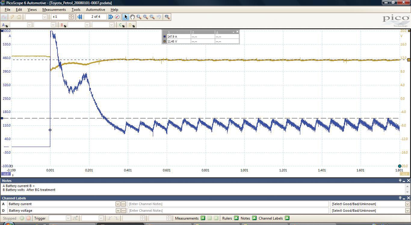
About now, you’re probably wondering where all the sludge went and whether it built up in the engine oil passages or the sump oil pick-up strainer. It hadn’t – the sludge that was dissolved during treatment was captured in the products and drained. I found no residue in the oil drainer or filters. Started the engine and checked the oil pressure – it was OK. Performed another relative compression test at approximately the same temperature as before showing an increase to 147.9A (pic 8), indicating possibly improved compression and uniform cylinder contributions.
Before road-testing the vehicle, I investigated the potential problem with the oil light not working. Reinstalled the oilpressure switch into the engine and found it was working correctly open circuit KOEO and closed circuit KOER.
Checked the instrument cluster with a torch and found no oil-can symbol warning light. Checking the owner’s manual confirmed there was no warning light in the cluster. Further investigations included grounding the oil-pressure switch wire and setting the ignition to the ‘on’ position but once again there were no warnings on the dash.
Next, started the engine and – bingo – an orange triangle (master warning) lit up in
the centre of the instrument cluster (pic 9, red arrow), there was an audible ding and a red oil can with a warning ‘Low oil, see dealer’ was displayed on the infotainment system (pic 9, orange arrow), so the system was working as intended. It’s worth noting, however, that a broken wire or open circuit oil-pressure switch will mean the oil-system warning will not work at all during a failure. Road tests confirmed the car performed well, with no smoking or rattling. During a follow-up, the customer reported smoother performance, better fuel economy and minimal oil consumption.
If you are sceptical about lotions and potions being add to oil or fuel systems, I’m hearing you… however, they certainly have their place in some cases.
Some of the trade-based products we professional technicians have access to can deliver great outcomes because a lot of R&D has gone into developing them and they have proven results and technical back-up. This case study certainly highlights that BG Dynamic Engine Restoration Treatment is a great product that works exceptionally well, delivering a great result and very happy customer.
Happy diagnosing!
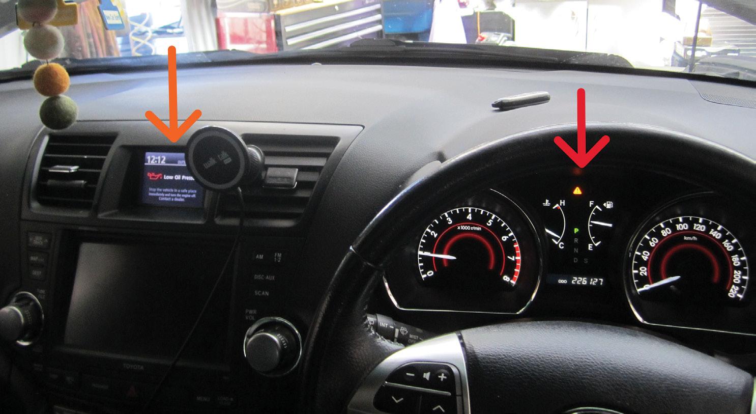

It’s natural to assume most employees are motivated by money. However, those who have been in the industry for a while know this is not always the case and when it comes to long-term employee motivation, there’s much more to it than just a healthy pay packet.
Before exploring what motivates employees, we need to highlight that money is important and everyone needs to earn enough to cover the needs of life. People have to pay the rent or mortgage, put food on the table and take care of their families. If someone worries each week their pay will not cover their financial needs, they will start to look over the fence for greener grass.
When people are looking for employment, money will naturally be at the top of the list but once they are hired, no amount of money can motivate them if they are not happy in their workplace.
Understanding employee motivation is crucial for those looking to improve productivity and retain employees long term. People have different motivations, so workshop owners need to build strong relationships with their employees to find out what truly motivates them. Consider the following.
Providing learning and development opportunities is a powerful motivator for employees. These opportunities can be both intrinsic and extrinsic motivators. Intrinsically, employees gain a sense of accomplishment and personal growth by acquiring new skills and knowledge. Extrinsically, they become more valuable to the organisation, potentially leading to promotions and wage increases. Offering regular training sessions, workshops and access to industry certifications can

help employees stay updated with the latest automotive technologies and repair techniques, fostering a culture of continuous improvement.
Beyond physical safety, creating a supportive and inclusive atmosphere where employees feel valued and respected can significantly enhance their motivation. Encouraging open communication, recognising achievements and fostering a sense of belonging can help employees flourish and feel happy in their roles.
Maintaining a proper work/life balance is vital to prevent employee demotivation and turnover. Offering flexible working schedules, allowing for personal time off and promoting a healthy work/life balance can help employees recharge and maintain their enthusiasm for their work. By respecting employees’ personal lives and commitments, employers can build a loyal and motivated workforce.
Positive feedback is a simple yet effective way to motivate employees. Recognising and appreciating employees’ efforts and achievements can boost their morale and job satisfaction. Regularly sharing


positive feedback, whether through verbal praise, written commendations or public recognition, helps employees feel fulfilled by their work and encourages them to continue performing at their best.
Incentives are powerful motivators that can drive employees to excel in their roles. These can be monetary, such as bonuses or profit-sharing schemes, or non-monetary, such as additional time off, gift vouchers or recognition awards. Incentives not only motivate employees to work well but also foster a sense of loyalty to the organisation. By aligning incentives with performance goals, employers can create a motivated and goal-oriented workforce.
Regular performance reviews and oneon-one meetings provide opportunities for employees to discuss their progress, set goals and receive guidance. This ongoing dialogue fosters a culture of transparency and continuous development.
Positive relationships with colleagues can significantly impact employee motivation. A collaborative and supportive team environment fosters camaraderie and a sense of belonging. Encouraging teamwork, organising team-building activities and promoting open communication can strengthen relationships among employees, leading to increased motivation and job satisfaction. Infighting between employees is a real problem and needs to be understood, addressed and nipped in the bud ASAP.
Efficient and streamlined business processes can enhance employee motivation by reducing frustration and increasing productivity. Providing
employees with the necessary tools, resources and technology to perform their tasks efficiently can lead to a more motivated workforce. Regularly reviewing and optimising business processes can help identify areas for improvement and ensure employees can focus on their core responsibilities.
Recognising the importance of employees’ personal lives is crucial for motivation. Employers who show empathy and understanding towards employees’ personal challenges and commitments can build trust and loyalty. Offering support such as flexible working arrangements or employee-assistance programmes can help employees manage personal issues without compromising their work performance. In conclusion, employee motivation is multifaceted, involving much more than money. Offering good money will help you recruit new employees but it will do little to motivate them long term. With the start of the new year just behind us, now is the time to review what you are doing to motivate and retain your staff.

TaT Biz is the businesstraining arm of TaT that specialises in business coaching for automotive workshops.
Geoff Mutton specialises in one-on-one business coaching for automotive workshops. For more info visit tatbiz.net.au


by Jeff Smit
In the high-octane world of Supercars racing, the drivers often steal the spotlight but the unsung heroes who keep these machines running at peak performance are the mechanics and technicians working behind the scenes.
One such rising star is Anthony Green, a third-year mechanic and technician with the Tickford Racing team.
From passion to profession
Anthony’s journey into motorsport began with a deep-rooted passion for cars and racing. Growing up in Melbourne, he was always fascinated by engines, tinkering with anything that had wheels and a motor. While studying in 2020 at The Kangan Institute in Melbourne, his teacher Greg suggested a two-week work experience with the prestigious Tickford Racing, one of the top teams in the the Repco Supercars Championship. Those two weeks went well and he was offered a oneyear internship, which he said was financially tough but ultimately worth it to be able to follow a dream.
In 2021, Anthony’s dream came true when he officially joined the Tickford Racing organisation. Tickford Racing is renowned for its competitive edge, fielding some of the best drivers and cars in the sport. Being part of such a high-calibre team is no small feat for a mechanic and Anthony quickly proved he was up to the challenge.
As a third-year mechanic/technician, Anthony plays a role in ensuring that Tickford’s cars, especially those in the Dunlop series, are finely tuned and ready to perform at their best in every race.

From engine diagnostics to suspension adjustments, his expertise is growing in a wide range of technical areas. Working closely with drivers and engineers, Anthony is learning that a technician’s role is not just about fixing problems but anticipating them before they arise.
One key attribute that sets Anthony apart is his attention to detail. In a sport where races are won or lost by milliseconds, even the smallest technical issue can make a world of difference. Anthony’s thoroughness, together with the other Tickford technicians, ensures that every car Tickford fields is in top shape, giving drivers the confidence to push their vehicles to the limit.
Working in motorsport presents unique challenges that go beyond regular mechanical work. The pressure is intense, with tight deadlines, long hours and the ever-present possibility of unexpected breakdowns. For Anthony, staying calm under pressure is second nature. Whether it’s performing rapid pit stops during a race or diagnosing issues in the garage, his ability to think on his feet is a vital asset to the team. Anthony’s hands-on experience with Tickford has also given him insight into the cutting-edge technology that powers modern V8 Supercars. From advanced telemetry systems to state-of-the-art materials used in construction, the work requires a blend of traditional mechanical skills and knowledge of high-tech innovations. Anthony’s ability to adapt to new technologies has made him a key part of Tickford’s racing strategy.

As Anthony enters his fourth year with Tickford Racing, his future in motorsport looks bright. His dedication to his craft and commitment to excellence have already earned him respect within the team and the broader Supercars community. With a team like Tickford that is always aiming for the top, he has the opportunity to continue honing his skills and contributing to the team’s ongoing success.
For Anthony, the ultimate reward is seeing the cars he works on cross the finish line at the front of the pack. While the drivers may get the glory, it’s the hard work of mechanics like Anthony Green that makes it all possible.
Anthony may be in the background of Tickford Racing’s success but his role is indispensable.
As a third-year mechanic and technician, he is a vital cog in the machine that powers one of Australia’s most successful Supercar teams. With his passion, technical expertise and ability to thrive under pressure, he is on a trajectory that could see him become one of the top mechanics in Australian motorsport.
We hope Anthony’s story and journey so far encourage more young people into the field of automotive mechanics, even possibly following in his footsteps and joining the exciting environment of motor racing.